1
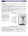
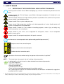
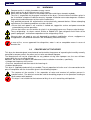
AMD 33-168
REFRIGERATING AIR DRYER
EN
USER’S MAINTENANCE AND SPARE PARTS MANUAL
7425MUM073_EN_2008-05
-ENEN-
AMD 33-168
Dear Customer,
thank you for choosing our product. In order to get the best performances out of this product, please read
this manual carefully.
To avoid incorrect operation of the equipment and possible physical risk to the operator, please read and
strictly follow the instructions contained in this manual.
Note, these instructions are in addition to the safety rules that apply in the country where the dryer is
installed. Before packing for shipment each AMD series refrigerated air dryer undergoes a rigorous test to
ensure the absence of any manufacturing faults and to demonstrate that the device can perform all the
functions for which it has been designed.
Once the dryer has been properly installed according to the instructions in this manual, it will be ready for
use without any further adjustment. The operation is fully automatic, and the maintenance is limited to few
controls and some cleaning operations, as detailed in the following chapters.
This manual must be maintained available in any moment for future references and it has to be
intended as inherent part of the relevant dryer.
Due to the continuous technical evolution, we reserve the right to introduce any necessary change without
giving previous notice.
Should you experience any trouble, or for further information, please do not hesitate to contact us.
DATA NAMEPLATE
The data nameplate is located
on the back of the dryer and
shows all the primary data of the
machine. Upon installation, fill in
the table on the previous page
with all the data shown on the
data nameplate. This data
should always be referred to
when calling the manufacturer
or distributor.
The removal or alteration of the
data nameplate will void the
warranty rights.
Model
Serial No.
Code
Nominal Flow Rate
Max Air Pressure
Model
Serial No.
Code
Nominal Flow Rate
Max Inlet Air Temp. Ambient Temp. Refrigerant (Type and qty) Refrig. Design Pres. HP/LP Electric Supply Electric Nominal Power Max Air Pressure
barg
Max Inlet Air Temp.
°C
Ambient Temp.
°C
Refrigerant
type/kg
Refrig. Design Pres. HP/LP
Electric Supply
Fuse Max. Manufactured Nl/min
barg
ph/V/Hz
Electric Nominal Power
W/A
Fuse Max.
A
TAD0006
Manufactured
WARRANTY CONDITIONS
For 12 months from the installation date, but no longer than 14 months from the delivery date, the warranty
covers eventual faulty parts, which will be repaired or replaced free of charge, except the travel, hotel and
restaurant expenses of our engineer.
The warranty doesn’t cover any responsibility for direct or indirect damages to persons, animals or
equipment caused by improper usage or maintenance, and it’s limited to manufacturing faults only.
The right to warranty repairs is subordinated to the strict compliance with the installation, use and
maintenance instructions contained in this manual.
The warranty will be immediately voided in case of even small changes or alterations to the dryer. To
require repairs during the warranty period, the data reported on the identification plate must be notified.
AMD 33-168
1.
SAFETY RULES
1.1.
1.2.
1.3.
1.4.
2.
INSTALLATION
2.1.
2.2.
2.3.
2.4.
2.5.
2.6.
2.7.
2.8.
3.
Definition of the Conventional Signs Used in This Manual
Warnings
Proper use of the dryer
Instructions for the use of pressure equipment according to ped directive 97/23/ec
Transport
Storange
Installation site
Installation layout
Correction factors
Connection to the compressed air system
Electrical connections
Condensate drain
START UP
3.1. Preliminary operation
3.2. First start-up
3.3. Start-up and shut down
4.
TECHNICAL SPECIFICATIONS
4.1.
4.2.
4.3.
4.4.
4.5.
5.
DESCRIZIONE TECNICA
5.1.
5.2.
5.3.
5.4.
5.5.
5.6.
5.7.
5.8.
5.9.
5.10.
5.11.
5.12.
5.13.
6.
Control panel
Operation
Flow diagram
Refrigerating compressor
Condenser
Filter drier
Capillary tube
Alu-dry module
Hot gas by-pass valve
Refrigerant pressure switches Pa- Pb- Pv
Safety thermo-switc TS
DMC15 Electronic instrument (Air Dryer Controller)
Electronic level drain
MAINTENANCE, TROUBLESHOOTING, SPARES AND DISMANTLING
6.1.
6.2.
6.3.
6.4.
6.5.
7.
Technical specifications AMD 3-25 / 230V / 50-60 Hz
Technical specifications AMD 32-168 / 230V / 50Hz
Technical specifications AMD 32E-168E / 230V / 60 Hz
Technical specifications AMD 3P-25P / 115V / 60 Hz
Caratteristiche tecniche AMD 32P-75P / 115V / 60 Hz
Controls and maintenance
Troubleshooting
Spare parts
Maintenance operation on the refrigerating circuit
Dismantling of the dryer
LIST OF ATTACHMENTS
7.1. Dryers dimensions
7.2. Exploded view
7.3. Electic diagrams
-ENEN-
-ENEN-
AMD 33-168
1. SAFETY RULES
1.1.
DEFINITION OF THE CONVENTIONAL SIGNS USED IN THIS MANUAL
Carefully read instruction manual before attempting any service or maintenance procedures on the
dryer.
Caution warning sign. Risk of danger or possibility of damage to equipment, if related text is not
followed properly.
Electrical hazard. Warning message indicates practices or procedures that could result in personal
injury or fatality if not followed correctly.
Danger hazard. Part or system under pressure.
Danger hazard. High temperature conditions exist during operation of system. Avoid contact until
system or component has dissipated heat.
Danger hazard. Treated air is not suitable for breathing purposes; serious injury or fatality may
result if precautions are not followed.
Danger hazard: In case of fire, use an approved fire extinguisher, water is not an acceptable
means in cases of fire.
Danger hazard. Do not operate equipment with panels removed.
1
Maintenance or control operation to be performed by qualified personnel only .
ARIA
AIR
LUFT
AIR
Compressed air inlet connection point.
ARIA
AIR
LUFT
AIR
Compressed air outlet connection point.
Condensate drain connection point.
1
Operations which can be worked out by the operator of the machine, if qualified .
NOTE :
Text to be taken into account, but not involving safety precautions.
In designing this unit a lot of care has been devoted to environmental protection:
• CFC free refrigerants
• CFC free insulation parts
• Energy saving design
• Limited acoustic emission
• Dryer and relevant packaging composed of recyclable materials
This symbol requests that the user heed environmental considerations and abide with suggestions
annotated with this symbol.
1
Experienced and trained personnel acquainted with the relevant rules and laws, capable to perform the needed activities and to identify and
avoid possible dangerous situations while handling, installing, using and servicing the machine.
AMD 33-168
-ENEN-
1.2.
WARNINGS
Compressed air is a highly hazardous energy source.
Never work on the dryer with pressure in the system.
Never point the compressed air or the condensate drain outlet hoses towards anybody.
The user is responsible for the proper installation of the dryer. Failure to follow instructions given in
the “Installation” chapter will void the warranty. Improper installation can create dangerous situations
for personnel and/or damages to the machine could occur.
Only qualified personnel are authorized to service electrically powered devices. Before attempting
maintenance, the following conditions must be satisfied :
• Ensure that main power is off, machine is locked out, tagged for service and power cannot be
restored during service operations.
• Ensure that valves are shut and the air circuit is at atmospheric pressure. De-pressurize the dryer.
These refrigerating air dryers contain R134a or R404A HFC type refrigerant fluid. Refer to the
specific paragraph - maintenance operation on the refrigerating circuit.
Warranty does not apply to any unit damaged by accident, modification, misuse, negligence or
misapplication. Unauthorized alterations will immediately void the warranty.
In case of fire, use an approved fire extinguisher, water is not an acceptable means in cases of
electrical fire.
1.3.
PROPER USE OF THE DRYER
This dryer has been designed, manufactured and tested for the purpose of separating the humidity normally
contained in compressed air. Any other use has to be considered improper.
The Manufacturer will not be responsible for any problem arising from improper use; the user will bear
responsibility for any resulting damage.
Moreover, the correct use requires the adherence to the installation instructions, specifically:
• Voltage and frequency of the mains.
• Pressure, temperature and flow-rate of the incoming air.
• Ambient temperature.
This dryer is supplied tested and fully assembled. The only operation left to the user is the connection to the
plant in compliance with the instructions given in the following chapters.
The purpose of the machine is the separation of water and eventual oil particles present in
compressed air. The dried air cannot be used for breathing purposes or for operations leading to
direct contact with foodstuff.
This dryer is not suitable for the treatment of dirty air or of air containing solid particles.
-ENEN-
1.4.
AMD 33-168
INSTRUCTIONS FOR THE USE OF PRESSURE EQUIPMENT ACCORDING TO PED
DIRECTIVE 97/23/EC
To ensure the safe operation of pressure equipments, the user must conform strictly to the above directive
and the following :
1. The equipment must only be operated within the temperature and pressure limits stated on the
manufacturer’s data nameplate.
2. Welding on heat-exchanger is not recommended.
3. The equipment must not be stored in badly ventilated spaces, near a heat source or inflammable
substances;
4. Vibration must be eliminated from the equipment to prevent fatigue failure.
5. Automatic condensate drains should be checked for operation every day to prevent a build up of
condensate in the pressure equipment.
6. The maximum working pressure stated on the manufacturer’s data nameplate must not be exceeded.
Prior to use, the user must fit safety / pressure relief devices.
7. All documentation supplied with the equipment (manual, declaration of conformity etc.) must be kept
for future reference.
8. Do not apply weights or external loads on the vessel or its connecting piping.
TAMPERING, MODIFICATION AND IMPROPER USE OF THE PRESSURE EQUIPMENT ARE
FORBIDDEN. Users of the equipment must comply with all local and national pressure
equipment legislation in the country of installation.
2. INSTALLATION
2.1.
TRANSPORT
Check for visible loss or damage, if no visible damage is found place the unit near to the installation point
and unpack the contents.
• Always keep the dryer in the upright vertical position. Damage to components could result if unit is laid on
its side or if placed upside down.
• Store machine in a clean, dry environment, do not expose to severe weather environments.
• Handle with care. Heavy blows could cause irreparable damage.
2.2.
STORANGE
Even when packaged, keep the machine
protected from severity of the weather.
Keep the dryer in vertical position, also when
stored. Turning it upside down some parts could
be irreparably damaged.
SCC0001
If not in use, the dryer can be stored in its
packaging in a dust free and protected site at a
maximum temperature of 50 °C, and a specific
humidity not exceeding 90%. Should the
stocking time exceed 12 months, please contact
the manufacturer.
The packaging materials are recyclable. Dispose of material in compliance with the rules
and regulations in force in the destination country.
AMD 33-168
-ENEN-
2.3.
INSTALLATION SITE
Failure to install dryer in the proper ambient conditions will affect the dryer’s ability to condense
refrigerant gas. This can cause higher loads on the compressor, loss of dryer efficiency and
performance, overheated condenser fan motors, electrical component failure and dryer failure due
to the following: compressor loss, fan motor failure and electrical component failure. Failures of
this type will affect warranty considerations.
Do not install dryer in an environment of corrosive chemicals, explosive gasses, poisonous
gasses; steam heat, areas of high ambient conditions or extreme dust and dirt.
Don’t use water to extinguish fire on the dryer
on in the surrounding area.
Minimal installation requirements :
• Select a clean room dry, free from dust, and protected
from atmospheric disturbances.
• The supporting area must be smooth, horizontal and
able to hold the weight of the dryer.
• Minimum ambient temperature +1 °C.
• Maximum ambient temperature +45°C.
• Leave at least 1 meter of free space on every side of
the drier for ventilation purposes and maintenance
operations.
The dryer doesn't require to be fixed to the supporting
surface. The dryer needs to be fixed to the supporting
surface only with particular installation procedures
(dryer on brakets, hanging units, etc.)
Dryer hanging (AMD 3-32 only):
Dryer
AMD 3
AMD 6-18
AMD 25
AMD 32
A [mm]
20
25
40
40
B [mm]
305
465
360
385
C [mm]
20
25
20
20
D [mm]
30
30
30
30
-ENEN-
AMD 33-168
2.4.
INSTALLATION LAYOUT
-AIN
1
7
OUT
3
4
5
8
1
2
3
4
6
9
2
9
9
9
8
Pre-Filter (min. 5 micron)
By-pass group
Dryer
Compressed air tank
Final filter
9
Condensate drain
5
6
-B-
7
IN
7
OUT
3
4
5
8
Air compressor
Final refrigerator
Condensate separator
DGT0002
1
6
9
2
9
9
9
In case of heavily polluted inlet air (ISO 8573.1 class 3.-.3 or worse quality), we recommend
the additional installation of a pre-filter (5 micron minimum) to prevent a clogging of the
heat exchanger.
Type A installation is suggested when the compressor operates at reduced intermittence and the total
consumption equals the compressor flow rate.
Type B installation is suggested when the air consumption can consistently change with peak values highly
exceeding the flow rate of the compressors. The capacity of the tank must be sized in order to compensate
eventual instantaneous demanding conditions (peak air consumption).
AMD 33-168
-ENEN-
2.5.
CORRECTION FACTORS
Correction factor for operating pressure changes :
Inlet air pressure
barg
4
5
6
Factor (F1)
0.77 0.86 0.93
7
1.00
8
1.05
Correction factor for ambient temperature changes (Air-Cooled):
Ambient temperature
ºC
25
30
Factor (F2)
1.00
0.98
Correction factor for inlet air temperature changes:
Air temperature
30
35
ºC
Factor (F3)
1.15
1.00
Correction factor for DewPoint changes:
DewPoint
ºC
3
Factor (F4)
0.91
10
1.14
12
1.21
35
0.95
14
1.27
15
1.30
40
0.88
16
1.33
45
0.80
40
45
50
55
0.84
0.71
0.59
0.50
5
1.00
7
1.10
10
1.26
How to find the air flow capacity:
Air flow capacity = Nominal duty x Factor (F1) x Factor (F2) x Factor (F3) x Factor (F4)
Example:
An AMD 18 has a nominal duty of 1800 l/min. What is the maximum allowable flow through the dryer under
the following operating conditions:
– Inlet air pressure = 7 barg
– Factor (F1) = 1.00
– Ambient temperature = 35°C
– Factor (F2) = 0.95
– Inlet air temperature = 40°C
– Factor (F3) = 0.84
– Pressure DewPoint = 3°C
– Factor (F4) = 0.91
Each item of data has a corresponding numerical factor which multiplied by the design air flow is as follows:
Air flow capacity = 108 x 1.00 x 0.95 x 0.84 x 0.91 = 1307 l/min
1307 l/min This is the maximum flow rate that the dryer can accept under these operating conditions.
How to select a suitable dryer for a given duty:
Minimum std. air flow rate =
Design air flow
Factor (F1) x Factor (F2) x Factor (F3) x Factor (F4)
Example:
With the following operating parameters:
–
–
–
–
–
Design air flow = 1100 l/min
Inlet air pressure = 7 barg
Ambient temperature = 35°C
Inlet air temperature = 40°C
Pressure DewPoint = 3°C
– Factor (F1) = 1.00
– Factor (F2) = 0.95
– Factor (F3) = 0.84
– Factor (F4) = 0.91
In order to select the correct dryer model the required flow rate is to be divided by the correction factors relating
to above mentioned parameters:
1100
Minimum std. air flow rate =
= 1515 l/min
1.00 x 0.95 x 0.84 x 0.91
Therefore the model suitable for the conditions above is AMD 18 (1800 l/min - nominal duty).
-ENEN-
AMD 33-168
2.6.
CONNECTION TO THE COMPRESSED AIR SYSTEM
Operations to be performed by qualified personnel. Never operate with plants under pressure.
The user is responsible to ensure that the dryer will never be operated with pressure exceeding
the nominal values.
Eventual over-pressure could be dangerous both for the operator and the machine.
The temperature and the amount of air entering the dryer must comply with the limits reported on the data
plate. In case of treatment of air at particularly high temperatures, the installation of a final refrigerator could
result necessary. The cross section of the connecting piping, which must be free from dust, rust, chips and
other impurities, must be consistent with the flow-rate of the dryer.
In order to facilitate the maintenance operations, a by-pass group has been installed, as shown in the
following illustration.
BPY0001
Dryer
AMD 3
AMD 6-18
AMD 25
AMD 32-52
AMD 61-75
AMD 105-130
AMD 168
Ø
Ø [BSP-F]
A [mm]
By-Pass Code
G 3/8” BSP-F
G 1/2” BSP-F
G 1” BSP-F
G 1.1/4” BSP-F
G 1.1/2” BSP-F
G 2” BSP-F
G 2.1/2” BSP-F
40
210
205
205
235
345
410
2240GBP019
2240GBP021
2240GBP022
2240GBP023
2240GBP024
2240GBP025
2240GBP026
In realising the dryer, particular measures have been taken in order to limit the vibration which could occur
during the operation. Therefore we recommend to use connecting pipes able to insulate the dryer from
possible vibrations originating from the line (flexible hoses, vibration damping fittings, etc.).
CAUTION:
PIPING THE DRYER, INLET/OUTLET CONNECTIONS MUST BE SUPPORTED AS
SHOW IN THE DIAGRAM.
FAILING WILL RESULT IN DAMAGE
AMD 33-168
-ENEN-
2.7.
ELECTRICAL CONNECTIONS
Qualified personnel should carry out connecting unit to the main power. Be sure to check the local
codes in your area.
Before connecting the unit to the electrical supply, verify the data nameplate for the proper electrical
information. Voltage tolerance is +/- 5%.
AMD 3-75 dryers are supplied with a standard VDE 16A - Shucko power cord and plug assembly (two
poles and a ground). AMD 105-168 dryers are supplied with a junction box.
Be sure to provide the proper fuses or breakers based on the data tag information located on the back of
the unit. The main power receptacle must be protected with a thermal overload/differential relay
(I∆n=0.03A), rated to the power consumption of the dryer (refer to data nameplate for nominal values). The
power supply cord must meet or exceed ratings for the total amp draw of the unit.
Connect to a properly grounded outlet. Improper connection of the equipment-grounding
conductor can result in risk of electric shock.
Do not use adapters on the plug receptacle - if it does not fit the outlet, have a proper outlet
installed by a qualified electrician.
2.8.
CONDENSATE DRAIN
The condensate is discharge at the system pressure.
Drain line should be secured
Never point the condensate drain line towards anybody.
The dryer comes with a flexible plastic drain tube.
The condensate drain occurs through a solenoid valve protected with a mechanical strainer.
The condensate coming from the separator is previously filtered, then discharged.
The solenoid valve coil is operated by electronic instrument (dryer controller).
If an electronic drainer is installed, the intervention times are determined by the internal capacitive sensor
(see specific paragraph).
The drainers cannot be connected to pressurized systems.
Don’t dispose the condensate in the environment.
The condensate collected in the dryer contains oil particles released in the air by the compressor.
Dispose the condensate in compliance with the local rules.
We suggest to install a water-oil separator where to convey all the condensate drain coming from
compressors, dryers, tanks, filters, etc.
3. START UP
3.1.
PRELIMINARY OPERATION
Verify that the operating parameters match with the nominal values reported on the data plate of the
dryer (voltage, frequency, air pressure, air temperature, ambient temperature, etc.).
Before delivery, each dryer is submitted to accurate tests simulating real operating conditions.
Nevertheless, the unit could be damaged during transportation. We therefore suggest to check the integrity
of the dryer upon arrival and to keep it under control during the first hours of operation.
The start-up must be performed by qualified personnel.
It’s mandatory that the engineer in charge adopt safety operational conditions complying with the
local safety and accident prevention requirements.
The same engineer will be responsible for the proper and safe operation of the dryer.
Never operate the dryer if the panels are not in place.
-ENEN-
AMD 33-168
3.2.
FIRST START-UP
This procedure should be followed on first start-up, after periods of extended shutdown or
following maintenance procedures.
Qualified personnel must perform the start-up.
Sequence of operations (refer to paragraph 5.1 Control Panel) :
• Ensure that all the steps of the “Installation” chapter have been observed.
• Ensure that the connection to the compressed air system is correct and that the piping is suitably fixed
and supported.
• Ensure that the condensate drain pipe is properly fastened and connected to a collection system or
container.
• Ensure that the by-pass system (if installed) is open and the dryer is isolated
• Ensure that the manual valve of the condensate drain circuit is open.
• Remove any packaging and other material which could obstruct the area around the dryer.
• Activate the mains switch.
• Turn on the main switch - pos. 1 on the control panel.
• Ensure that the DMC15 electronic instrument is ON.
• Ensure the consumption matches with the values of the data plate.
• Ensure the fan work properly - wait for its first interventions.
• Allow the dryer temperature to stabilise at the pre-set value.
• Slowly open the air inlet valve.
• Slowly open the air outlet valve.
• Slowly close the central by-pass valve of the system (if installed).
• Check the piping for air leakage.
• Ensure the drain is regularly cycling - wait for its first interventions.
3.3.
START-UP AND SHUT DOWN
Start-up (refer to paragraph 5.1 Control Panel) :
Check the condenser for cleanliness.
Verify that the system is powered.
Turn on the main switch - pos. 1 on the control panel.
Ensure that DMC15 electronic instrument is ON.
Wait a few minutes; verify that the DewPoint temperature displayed on DMC15 electronic instrument is
correct and that the condensate is regularly drained.
• Switch on the air compressor.
•
•
•
•
•
Shut down (refer to paragraph 5.1 Control Panel) :
• Verify that the DewPoint temperature displayed on DMC15 electronic instrument is correct.
• Switch OFF the air compressor.
• After a few minutes, switch off the main switch on the control panel of the dryer (pos. 1).
NOTE : A DewPoint included in the green operating area of the electronic controller is correct
according to the possible working conditions (flow-rate, temperature of the incoming air, ambient
temperature, etc.)
During the operation, the refrigerating compressor will run continuously. The dryer must remain on during
the full usage period of the compressed air, even if the air compressor works intermittently.
The number of starts must be no more than 6 per hour. The dryer must stop running for at
least 5 minutes before being started up again.
The user is responsible for compliance with these rules. Frequent starts may cause
irreparable damage.
2
2
2
1
170 (220)
1.2 (1.3)
[W]
[A]
[kg]
21
1.1 (1.1)
[A]
[dbA]
150 (180)
G 3/8”
[W]
[Ph/V/Hz]
[m /h]
3
[kg]
[BSP-F]
[bar]
0.20
25
1.2 (1.4)
200 (250)
1.1 (1.2)
160 (190)
200
Check the data shown on the identification plate.
The nominal condition refers to an ambient temperature of +25°C with inlet air at 7 barg and +35 °C.
Weight
Max. level noise at 1 m
Max. electric absorption 50Hz (60Hz)
Nominal electric absorption 50Hz (60Hz)
Standard Power Supply
Cooling air flow
Refrigerant quantity
Refrigerant type
Inlet - Outlet connections
p
[barg]
Max. inlet air pressure
Air pressure drop -
[barg]
Nominal inlet air pressure
1.5 (1.6)
270 (290)
1.3 (1.3)
26
R134.a
G 1/2”
7
< 70
0.25
0.14
28
1.7 (1.8)
280 (340)
1.4 (1.5)
210 (250)
1/230/50-60
190 (210)
0.22
0.09
16
[°C]
Nominal inlet air temperature (max.)
32
2.2 (2.5)
390 (460)
1.9 (2.0)
290 (330)
300
0.30
0.32
64
108
1800
18
34
3.3 (3.4)
610 (670)
2.4 (2.5)
390 (460)
0.33
G 1”
0.24
14
88
150
2500
25
4.1.
+35 (+55)
+1
Pressure DewPoint at nominal condition
[°C]
42
Min. ambient temperature
34
72
1200
+25 (+45)
0.04
21
57
950
12
[°C]
0.15
12
[scfm]
36
600
9
Nominal ambient temperature (max.)
1
21
350
[m /h]
3
[l/min]
6
+5 equal to 0.85 g/m3 di H2O
1
3
[°C]
Air flow rate at nominal condition
AMD MODEL
Air-Cooled
AMD 33-168
-ENEN-
4. TECHNICAL SPECIFICATIONS
TECHNICAL SPECIFICATIONS AMD 3-25 / 230V / 50-60 HZ
2
2
2
1
700
3.8
[W]
[A]
[kg]
39
2.9
[A]
[dbA]
480
350
0.44
R134.a
[Ph/V/Hz
]
[W]
[m /h]
3
[kg]
[BSP-F]
[bar]
40
5.4
1150
3.3
750
380
0.40
G 1.1/4”
41
6.6
1350
4.6
930
600
0.42
Check the data shown on the identification plate.
The nominal condition refers to an ambient temperature of +25°C with inlet air at 7 barg and +35 °C.
Weight
Max. level noise at 1 m
Max. electric absorption
Nominal electric absorption
Standard Power Supply
Cooling air flow
Refrigerant quantity
Refrigerant type
Inlet - Outlet connections
p
[barg]
Max. inlet air pressure
Air pressure drop -
[barg]
Nominal inlet air pressure
54
6.8
0.25
< 70
3.6
740
56
4.8
1050
1/230/50
450
0.70
R404A
G 1.1/2”
1400
4.7
950
400
0.57
0.19
14
7
94
6.3
1350
4.3
940
1.10
0.14
371
630
10500
105
G 2”
96
9.8
2100
7.4
1550
1900
1.30
0.20
459
780
13000
130
144
11.3
2350
7.5
1590
1.90
G 2.1/2”
0.15
594
1008
16800
168
4.2.
+35 (+55)
[°C]
Nominal inlet air temperature (max.)
Pressure DewPoint at nominal condition
+1
265
[°C]
216
450
7500
Min. ambient temperature
0.34
184
366
6100
75
+25 (+45)
0.24
152
312
5200
61
[°C]
0.16
113
[scfm]
258
4300
52
Nominal ambient temperature (max.)
1
192
3200
[m /h]
3
[l/min]
43
+5 equal to 0.85 g/m3 di H2O
1
32
[°C]
Air flow rate at nominal condition
AMD MODEL
Air-Cooled
-ENENAMD 33-168
TECHNICAL SPECIFICATIONS AMD 32-168 / 230V / 50HZ
2
2
2
1
720
4.3
[W]
[A]
[kg]
39
3.8
[A]
[dbA]
630
350
0.44
R134.a
[W]
[Ph/V/Hz]
[m /h]
3
[kg]
[BSP-F]
[bar]
42
5.9
1350
4.4
970
380
0.45
G 1.1/4”
45
6.2
1400
4.5
1000
0.47
Check the data shown on the identification plate.
The nominal condition refers to an ambient temperature of +25°C with inlet air at 7 barg and +35 °C.
Weight
Max. level noise at 1 m
Max. electric absorption
Nominal electric absorption
Standard Power Supply
Cooling air flow
Refrigerant quantity
Refrigerant type
Inlet - Outlet connections
p
[barg]
Max. inlet air pressure
Air pressure drop -
[barg]
Nominal inlet air pressure
600
1050
1460
54
6.6
900
0.85
R404A
< 70
56
5.7
1260
4.1
910
1/230/60
0.68
4.6
0.25
G 1.1/2”
0.19
14
7
+35 (+55)
[°C]
Nominal inlet air temperature (max.)
Pressure DewPoint at nominal condition
+1
265
[°C]
216
450
7500
Min. ambient temperature
0.34
184
366
6100
75E
+25 (+45)
0.24
152
312
5200
61E
[°C]
0.16
113
[scfm]
258
4300
52E
Nominal ambient temperature (max.)
1
192
3200
[m /h]
3
[l/min]
43E
+5 equal to 0.85 g/m3 di H2O
1
32E
94
7.2
1550
5.1
1150
1.20
0.14
371
630
10500
105E
2400
G 2”
96
13.2
2890
9.6
2070
1.40
0.20
459
780
13000
130E
144
14.5
2950
10.3
2250
2600
2.10
G 2.1/2”
0.15
594
1008
16800
168E
4.3.
[°C]
Air flow rate at nominal condition
AMD MODEL
Air-Cooled
AMD 33-168
-ENEN-
TECHNICAL SPECIFICATIONS AMD 32E-168E / 230V / 60 HZ
2
2
2
1
220
2.4
[W]
[A]
[kg]
21
2.2
[A]
[dbA]
180
0.20
G 3/8”
[W]
[Ph/V/Hz]
[m /h]
3
[kg]
[BSP-F]
[bar]
25
2.8
240
2.4
190
200
0.21
Check the data shown on the identification plate.
The nominal condition refers to an ambient temperature of +25°C with inlet air at 7 barg and +35 °C.
Weight
Max. level noise at 1 m
Max. electric absorption
Nominal electric absorption
Standard Power Supply
Cooling air flow
Refrigerant quantity
Refrigerant type
Inlet - Outlet connections
p
[barg]
Max. inlet air pressure
Air pressure drop -
[barg]
Nominal inlet air pressure
220
26
3.1
280
2.6
R134.a
G 1/2”
7
< 70
1/115/60
0.22
0.09
16
28
3.5
320
3.0
280
0.25
0.14
[°C]
Nominal inlet air temperature (max.)
32
3.9
460
3.5
420
300
0.30
0.32
64
108
1800
18P
34
6.0
650
5.1
490
0.33
G 1”
0.24
14
88
150
2500
25P
4.4.
+35 (+55)
+1
Pressure DewPoint at nominal condition
[°C]
42
Min. ambient temperature
34
72
1200
+25 (+45)
0.04
21
57
950
12P
[°C]
0.15
12
[scfm]
36
600
9P
Nominal ambient temperature (max.)
1
21
350
[m /h]
3
[l/min]
6P
+5 equal to 0.85 g/m3 di H2O
1
3P
[°C]
Air flow rate at nominal condition
AMD MODEL
Air-Cooled
-ENENAMD 33-168
TECHNICAL SPECIFICATIONS AMD 3P-25P / 115V / 60 HZ
2
2
2
1
42
11.8
Check the data shown on the identification plate.
12.4
1400
45
39
7.6
[A]
1350
9.0
[kg]
720
[W]
8.8
1000
1/115/60
0.47
< 70
6.5
[A]
970
380
0.45
0.34
14
7
[dbA]
630
350
0.44
R134.a
[W]
[Ph/V/Hz]
[m /h]
3
[kg]
[BSP-F]
[bar]
The nominal condition refers to an ambient temperature of +25°C with inlet air at 7 barg and +35 °C.
Weight
Max. level noise at 1 m
Max. electric absorption
Nominal electric absorption
Standard Power Supply
Cooling air flow
Refrigerant quantity
Refrigerant type
Inlet - Outlet connections
p
[barg]
Max. inlet air pressure
Air pressure drop -
[barg]
Nominal inlet air pressure
G 1.1/4”
600
R404A
[°C]
Nominal inlet air temperature (max.)
+35 (+55)
+1
[°C]
Pressure DewPoint at nominal condition
Min. ambient temperature
184
+25 (+45)
0.24
152
312
5200
[°C]
0.16
113
[scfm]
258
4300
52P
Nominal ambient temperature (max.)
1
192
3200
[m /h]
3
[l/min]
43P
+5 equal to 0.85 g/m3 di H2O
1
32P
54
13.2
1460
9.2
1050
0.68
0.19
216
366
6100
61P
G 1.1/2”
56
11.4
1260
8.2
910
900
0.85
0.25
265
450
7500
75P
4.5.
[°C]
Air flow rate at nominal condition
AMD MODEL
Air-Cooled
AMD 33-168
-ENEN-
CARATTERISTICHE TECNICHE AMD 32P-75P / 115V / 60 HZ
-ENEN-
AMD 33-168
5. DESCRIZIONE TECNICA
5.1.
CONTROL PANEL
The control panel illustrated below is the only dryer-operator interface.
AMD 3-61
K
1
ON
DMC15
0
sec - min
PQS0008
1
set
2
3
AMD 75-168
K
I
ON
ON
DMC15
sec - min
PQS0024
set
1
1
Main switch
2
Air Dryer Controller DMC15
3
2
3
5.2.
Air and refrigerating gas flow diagram
OPERATION
Operating principal –The dryer models described in this manual operate all on the same principal. The hot
moisture laden air enters an air to air heat exchanger. The air then goes through the evaporator, also known as
the air to refrigerant heat exchanger. The temperature of the air is reduced to approximately 2°C, causing water
vapor to condense to liquid. The liquid is continuously coalesced and collected in the separator for removal by the
condensate drain. The cool moisture free air then passes back through the air to air heat exchanger to be
reheated to within 8 degrees of the incoming air temperature as it exits the dryer.
Refrigerant circuit - Refrigerant gas is cycled through the compressor and exits at high pressure to a
condenser where heat is removed causing the refrigerant to condense to a high-pressure liquid state. The liquid is
forced through a capillary tube where the resulting pressure drop allows the refrigerant to boil off at a predetermined
temperature. Low-pressure liquid refrigerant enters the heat exchanger where heat from the incoming air is
transferred causing the refrigerant to boil; the resulting phase change produces a low pressure, low temperature
gas. The low-pressure gas is returned to the compressor, where it is re-compressed and begins the cycle again.
During those periods when the compressed air load is reduced the excess refrigerant is by-passed automatically
back to the compressor via the Hot Gas By-pass Valve circuit.
AMD 33-168
-ENEN-
5.3.
FLOW DIAGRAM
2
3
4
5
PB
TS
PA
PV
6
1a
7
9
1
1b
17
EC
8
M
12
T1
12.1
1c
11
DGF0004
10
T2
15
Standard
13
16
14
EC
ELD
21
Optional
3
Alu-Dry Module
a - Air-to-air heat exchanger
b - Air-to-refrigerant exchanger
c - Condensate separator
Refrigerant pressure-switch PB(AMD 168)
Safety thermo-switch TS
13
4
(AMD 43E-168E) - (AMD 43P-168P)
Refrigerant pressure-switch PA (AMD 105-168)
5
Refrigerant Fan pressure-switch PV
15
(AMD 43-168)
16
Refrigeration compressor
Hot gas by-pass valve
Condenser
17
1
2
6
7
8
Compressed air flow direction
Condenser fan
Filter drier
11 Capillary tube
12 T1 Temperature probe (DewPoint)
12.1 T2 Temperature probe (fan control)
9
10
(AMD 3-32)
14
Condensate drain isolation valve
Condensate drain strainer
Condensate drain solenoid valve
Coil for cond. drain solenoid valve
Air Dryer Controller
…
21
Electronic level drain
Refrigerating gas flow direction
-ENEN-
AMD 33-168
5.4.
REFRIGERATING COMPRESSOR
The refrigerating compressor is the pump of the system where the gas coming from the evaporator (low
pressure side) is compressed up to the condensation pressure (high pressure side). All the compressors
used are manufactured by primary companies and are designed for applications where high compression
ratios and wide temperature changes are present.
The fully sealed construction is perfectly gas tight, so ensuring high-energy efficiency and long useful life.
The pumping unit is supported by dumping springs, in order to consistently reduce the acoustic emission
and the vibration diffusion. The electric motor is cooled down by the aspirated refrigerating gas, which goes
through the coils before reaching the compression cylinders. The internal thermal protection protects the
compressor from overheating and overcurrents. The protection is automatically restored as soon as the
nominal temperature conditions are reached.
5.5.
CONDENSER
The condenser is the element in which the gas coming from the compressor is cooled down and condensed
becoming a liquid. Mechanically, it is formed by a copper tubing circuit (with the gas flowing inside)
immersed in an aluminium blades package.
The cooling operation occurs via a high efficiency axial ventilator which, in applying pressure on the air
contained within the dryer, forces it into the blades package.
It’s mandatory that the temperature of the ambient air will not exceed the nominal values. It’s important TO
KEEP THE UNIT FREE FROM DUST AND OTHER IMPURITIES.
5.6.
FILTER DRIER
Traces of humidity and slag can accumulate inside the refrigerating circuit. Long periods of use can also
produce sludge. This can limit the lubrication efficiency of the compressor and clog the expansion valve or
capillary tube. The function of the Filter Drier, located before the capillary tubing, is to eliminate any
impurities from circulating through the system.
5.7.
CAPILLARY TUBE
It consists of a piece of reduced cross section copper tubing located between the capacitor and the
evaporator to form a throttling against the flow of the refrigerating fluid. This throttling creates a pressure
drop, which is a function of the temperature to be reached within the evaporator: the lower the capillary tube
outlet pressure, the lower the evaporation temperature. The length and the diameter of the capillary tubing
are accurately sized with the performance to be reached by the dryer; no maintenance/adjustment
operations are necessary.
5.8.
ALU-DRY MODULE
The heat exchanger module houses the air-to-air, the air-to-refrigerant heat exchangers and the demister
type condensate separator. The counter flow of compressed air in the air-to-air heat exchanger ensures
maximum heat transfer. The generous cross section of flow channel within the heat exchanger module
leads to low velocities and reduced power requirements. The generous dimensions of the air-to-refrigerant
heat exchanger plus the counter flow gas flow allows full and complete evaporation of the refrigerant
(preventing liquid return to the compressor). The high efficiency condensate separator is located within the
heat exchanger module. No maintenance is required and the coalescing effect results in a high degree of
moisture separation.
AMD 33-168
-ENEN-
5.9.
HOT GAS BY-PASS VALVE
This valve injects part of the hot gas (taken from the discharge side of the compressor) in the pipe between
the evaporator and the suction side of the compressor, keeping the evaporation temperature/pressure
constant at approx. +2 °C. This injection prevents the formation of ice inside the dryer evaporator at every
load condition
ADJUSTMENT
A
4 mm
5/32 in.
VLY0002
The hot gas by-pass valve is adjusted during the manufacturing
testing phase. As a rule no adjustment is required; anyway if it is
necessary the operation must be carried out by an experienced
refrigeration engineer.
WARNING : the use of ¼” Schrader service valves must be
justified by a real malfunction of the refrigeration system. Each
time a pressure gauge is connected, a part of refrigerant is
exhausted.
Without compressed air flow through the dryer, rotate the adjusting
screw (position A on the drawing) until the following value is reached:
Hot gas setting (R134.a) : temperature 0.5 °C (+0.5 / -0 °K)
pressure 2.0 barg (+0.1 / -0 bar)
Hot gas setting (R404A) : temperature 0.5 °C (+0.5 / -0 °K)
pressure 5.2 barg (+0.1 / -0 bar)
+
5.10. REFRIGERANT PRESSURE SWITCHES PA- PB- PV
As operation safety and protection of the dryer a series of pressure switches are installed in the gas circuit.
PB :
Low-pressure controller device on the suction side of the compressor, is enabled only if the
pressure drops below the pre-set value. The values are automatically reset when the nominal
conditions are restored.
Calibrated pressure : R 404 A Stop 1.0 barg - Restart 5.0 barg
PA :
This high-pressure controller device is located at the pushing side of refrigeration compressor, and
it is activated when the pressure exceeds the pre-set value. It features a manual-resetting button
mounted on the controller itself.
Calibrated pressure : R 404 A Stop 32 barg - Manual reset
PV :
Fan control pressure switch is located at the pushing side of refrigeration compressor. It keeps the
condensation temperature/pressure constant within preset limits (Air-Cooled).
Calibrated pressure : R 404 A Start 20 barg (45°C) - Stop 16 barg (36°C) - Tolerance ± 1 bar
5.11. SAFETY THERMO-SWITC TS
2
PQS0005
1
To protect the operating safety and the integrity of the dryer, a thermoswitch (TS) is installed on the refrigerant gas circuit. The thermo-switch
sensor, in case of unusual discharge temperatures, stops the refrigerating
compressor before it is permanently damaged.
Manually reset the thermo-switch only after the nominal operating
conditions have been restored. Unscrew the relative cap (see pos.1 in the
figure) and press the reset button (see pos.2 in the figure).
TS setting :
temperature 100 °C (+2 / -2 °K)
-ENEN-
AMD 33-168
5.12. DMC15 ELECTRONIC INSTRUMENT (AIR DRYER CONTROLLER)
set
ON
DMC15
PQS0014
sec - min
set
Button - access the set-up.
Button - condensate drain test / value increment.
Green LED - glowing = power on.
Yellow LED - glowing = condensate drain solenoid valve on.
Yellow LED - glowing = condenser fan on.
(AMD 3-32)
DISPLAY
The DMC15 electronic controller performs the following functions : it shows the current operating DewPoint
through the digital led display which is detected from the (T1) probe located at the end of the evaporator,
while a second (T2) probe, located on the discharge side of the condenser, activates the relevant fan;
eventually it controls the functioning of condensate drain solenoid valve through the cyclic electronic timer.
OPERATION - During the dryer operation, the LED
is on.
Thermometer - The 10 LED display indicates the current operating DewPoint, shown by means of a two
colours (green - red) bar over the display itself.
• Green section - operating conditions ensuring an optimal DewPoint;
• Red section - DewPoint of the dryer too high, the dryer is working with elevated thermal load (high inlet
air temperature, high ambient temperature, etc.). The treatment of the compressed air may be improper.
Too high DewPoint temperature, value exceeding the upper limit of the instrument range, is indicated by the
intermittent flashing of the last LED; whereas the intermittent flashing of the first LED shows too low
DewPoint temperature.
A possible (T1) probe failure is indicated by the intermittent flashing of the first and last LED of the display,
whereas the dryer keeps on working correctly.
Thermostat (AMD 3-32) - The fan condenser is activated when the condensate temperature reaches or exceeds
on - and it is deactivated when the temperature goes down to 30°C (FANON - Hys) - LED
35°C (FANON) - LED
off. In case of (T2) probe failure, the fun will run continuously and the
LED will intermittent flash.
Timer - The condensate drain solenoid valve is activated for 2 seconds (TON) -
LED on - each minute
(TOFF), if standard setting. To perform the manual test for the condensate drain, press the
button.
SET-UP - The DMC15 is adjusted during the final test of the dryer. In case of particular requirements
concerning the operation management, the user can change the setting of the programmed parameters.
The parameters which can be set up are the following :
• FANON (AMD 3-32) - activation temperature of condenser fan. It is adjustable inside the following range
of values, with step of 1°K; whereas the Hys hysteresis is fixed and equal to -5ºK.
• TON - activation time of the condensate drain solenoid valve.
• TOFF - pause time between two consecutive activation of the condensate drain solenoid valve.
To access the set-up, keep the button set pressed for at least 2 seconds;
LED flashing confirms
the command. First appears the (FANON) parameter; to access the other parameters, press sequentially the
set
button. To change the value of the selected parameter, keep the
set
button pressed and operate
on button
; the current value is shown on the LED display. For the value range and the resolution
(value of each single LED), see the following table :
Parameter
Description
TON
(solo AMD 3-32)
Activation temperature
of condenser fan
Activation time of the condensate
drain solenoid valve
TOFF
Pause time of the condensate
drain solenoid valve
FANON
Display
Synchronous flashing
LED
+ LED
Synchronous flashing
LED
+ LED
Non-Synchronous flashing
LED
+ LED
To exit the set-up condition in any moment, press the
minutes, the system automatically exits the set-up condition.
Value range
Resolution
Set
value
31 - 40 °C
1°K
35°C
1 - 10 sec
1 sec
2 sec
1 - 10 min
1 min
1 min
button. If no operations are performed for 2
AMD 33-168
-ENEN-
5.13. ELECTRONIC LEVEL DRAIN
Instead of the usual drain system (a solenoid valve controlled by means of electronic instrument); an
electronic level controlled drain can be installed as option. This drain consists of a condensate accumulator
where a capacitive sensor continuously checking liquid level is placed: as soon as the accumulator is filled,
the sensor passes a signal to the electronic control and a diaphragm solenoid valve will open to discharge
the condensate. For a complete condensate discharge the valve opening time will be adjusted exactly for
each single drain operation. No condensate strainers are installed. No adjusting is required. A service valve
is installed before the electronic drain in order to make check and maintenance easily.
AT DRYER START-UP VERIFY THAT THIS VALVE IS OPEN.
CONTROL PANEL for Dryers AMD 3-105
The control panel here illustrated allows checking of drain working.
Power : LED - drain ready to work / supplied
Valve : slow blinking led - membrane solenoid valve open / discharging
Alarm : fast blinking led - drain in alarm condition
Test : button - discharge test (keep pushed for 2 seconds)
CONTROL PANEL FOR DRYERS AMD 3-105
The control panel here illustrated allows checking of drain working.
Power : LED - drain ready to work / supplied
Valve : led - membrane solenoid valve open / discharging
Alarm : blinking led - drain in alarm condition
Test : button - discharge test (keep pushed for 2 seconds)
TROUBLE SHOOTING
Only qualified personnel should perform troubleshooting and or maintenance operations.
Prior to performing any maintenance or service, be sure that:
• no part of the machine is powered and that it cannot be connected to the mains supply.
• no part of the machine is under pressure and that it cannot be connected to the compressed
air system.
• Maintenance personnel have read and understand the safety and operation instructions in
this manual.
SYMPTOM
POSSIBLE CAUSE - SUGGESTED ACTION
No led lighting up.
Verify that the system is powered.
Verify the electric wiring (internal and/or external).
Check internal printed circuit board for possible damage.
Pressing of Test button, but no condensate discharge.
The service valve located before the drain is closed - open it.
The dryer is not under pressure - restore nominal condition.
Solenoid valve defective - replace the drain.
The internal printed circuit board is damaged - replace the drain.
Condensate discharge The capacitive sensor is too dirty - open the drain and clean the sensor plastic
only when Test button
tube.
is pressed.
Drain keeps blowing off The diaphragm valve is dirty - open the drain and clean it.
air.
The capacitive sensor is too dirty - open the drain and clean the sensor plastic
tube.
Drain
in
condition.
alarm The capacitive sensor is too dirty - open the drain and clean the sensor plastic
tube.
The service valve located before the drain is closed - open it.
The dryer is not under pressure - restore nominal condition.
Solenoid valve defective - replace the drain.
NOTE : When the drain is in alarm condition, the diaphragm solenoid valve will open 7.5 sec every 4 min.
-ENEN-
AMD 33-168
6. MAINTENANCE, TROUBLESHOOTING, SPARES AND DISMANTLING
6.1.
CONTROLS AND MAINTENANCE
Only qualified personnel should perform troubleshooting and or maintenance operations.
Prior to performing any maintenance or service, be sure that:
• no part of the machine is powered and that it cannot be connected to the mains supply.
• no part of the machine is under pressure and that it cannot be connected to the
compressed air system.
• Maintenance personnel have read and understand the safety and operation instructions
in this manual.
Before attempting any maintenance operation on the dryer, shut it down and wait at least 30
minutes.
Some components can reach high temperature during operation. Avoid contact until system or
component has dissipated heat.
DAILY
• Verify that the DewPoint displayed on the electronic instrument is correct.
• Check the proper operation of the condensate drain systems.
• Verify the condenser for cleanliness.
EVERY 200 HOURS OR MONTHLY
• With an air jet (max. 2 bar / 30 psig) blowing from inside towards outside
clean the condenser; repeat this operation blowing in the opposite way; be
careful not to damage the aluminium fins of the cooling package.
• Close the isolation valve for the condensate drain, remove the mechanical filter and clean it with
compressed air and a brush. Reinstall the filter, make sure it is secure, and open the isolation valve.
• At the end, check the operation of the machine.
EVERY 1000 HOURS OR YEARLY
• Verify for tightness all the screws of the electric system and that all the “Faston” type
connections are in their proper position, inspect unit for broken, cracked or bare wires.
• Inspect refrigerating circuit for signs of oil and refrigerant leakage.
• Measure and record amperage. Verify that readings are within acceptable parameters as listed
in specification table.
• Inspect condensate drain flexible hoses, and replace if necessary.
• At the end, check the operation of the machine.
AMD 33-168
-ENEN-
6.2.
TROUBLESHOOTING
Only qualified personnel should perform troubleshooting and or maintenance operations.
Prior to performing any maintenance or service, be sure that:
• no part of the machine is powered and that it cannot be connected to the mains supply.
• no part of the machine is under pressure and that it cannot be connected to the compressed air
system.
• Maintenance personnel have read and understand the safety and operation instructions in this
manual.
Before attempting any maintenance operation on the dryer, shut it down and wait at least 30
minutes.
Some components can reach high temperature during operation. Avoid contact until system or
component has dissipated heat.
SYMPTOM
The dryer doesn't start.
The compressor doesn’t
work.
POSSIBLE CAUSE - SUGGESTED ACTION
Verify that the system is powered.
Verify the electric wiring.
Activation of the compressor internal thermal protection - wait for 30 minutes, then
retry.
Verify the electric wiring.
Where installed- Replace the internal thermal protection and/or the start-up relay
and/or the start-up capacitor and/or the working capacitor.
Where installed- The pressure switch PA has been activated - see specific point.
Where installed- The pressure switch PB has been activated - see specific point.
Where installed- The safety thermo-switch TS has been activated - see specific
point.
If the compressor still doesn’t work, replace it.
The fan of the condenser
doesn’t work.
DewPoint too low.
AMD 3-32 - The fan is always ON - the
yellow LED of DMC15 controller is
glowing continuously - see specific point.
AMD 43-168 - The fan is always ON - PV pressure switch is faulty - replace it.
Ambient temperature is too low - restore de nominal condition.
The hot gas by-pass valve is out of setting - contact a refrigeration engineer to
restore the nominal setting.
DewPoint too high.
The dryer doesn't start - see specific point.
The T1 DewPoint probe doesn’t correctly detect the temperature - ensure the
Verify the electric wiring.
AMD 3-32 - The DMC15 electronic controller is faulty - replace it.
AMD 43-168 - PV pressure switch is faulty - replace it.
If the fan still doesn't work, replace it.
sensor is pushed into the bottom of copper tube immersion well.
The refrigerating compressor doesn’t work - see specific point.
The ambient temperature is too high or the room aeration is insufficient - provide
proper ventilation.
The inlet air is too hot - restore the nominal conditions.
The inlet air pressure is too low - restore the nominal conditions.
The inlet air flow rate is higher than the rate of the dryer - reduce the flow rate restore the normal conditions.
The condenser is dirty - clean it.
The condenser fan doesn’t work - see specific point.
The dryer doesn’t drain the condensate - see specific point.
The hot gas by-pass valve is out of setting - contact a refrigeration engineer to
restore the nominal setting.
There is a leak in the refrigerating fluid circuit - contact a refrigeration engineer.
Excessive pressure drop
within the dryer.
The dryer doesn’t drain the condensate - see specific point.
The DewPoint is too low - the condensate is frost and blocks the air - see specific
point.
Check for throttling the flexible connection hoses.
-ENEN-
AMD 33-168
The dryer doesn’t drain
the condensate.
The condensate drain service valve is closed - open it.
The condensate drain strainer is clogged - remove and clean it.
The drain solenoid valve is jammed - remove and clean it.
Verify the electric wiring.
The coil of the condensate drain solenoid valve burned out - replace it.
The DewPoint is too low - the condensate is frozen - see specific point.
The DMC15 electronic controller is faulty - replace it.
The dryer continuously
drains condensate.
The drain solenoid valve is jammed - remove and clean it.
Try to remove the electric connector on the solenoid valve - if drain stops verify the
electric wiring or the electronic instrument is faulty - replace it.
Water within the line.
The dryer doesn't start - see specific point.
Where installed - Untreated air flows through the by-pass unit - close the by-pass.
The dryer doesn’t drain the condensate - see specific point.
DewPoint too high - see specific point.
Where installed - The PA Check which of the following has caused the activation :
high-pressure switch has 1. The ambient temperature is too high or the room aeration is insufficient - provide
proper ventilation (Air-Cooled).
been activated.
2. The condenser is dirty - clean it (Air-Cooled).
3. The condenser fan doesn’t work - see specific point (Air-Cooled).
Reset the pressure-switch pressing the button on the controller itself - verify the
dryer for correct operation.
The PA pressure switch is faulty - contact a refrigeration engineer to replace it.
Where installed - The PB There is a leak in the refrigerating fluid circuit - contact a refrigeration engineer.
low-pressure switch has The pressure switch restores automatically when normal conditions are restored check the proper operation of the dryer.
been activated.
Where installed - The TS Check which of the following has caused the activation :
safety thermo-switch has 1. Eccessive thermal load – restore the standard operating conditions.
2. The inlet air is too hot - restore the nominal conditions.
been activated.
3. The ambient temperature is too high or the room aeration is insufficient - provide
proper ventilation.
4. The condenser unit is dirty - clean it.
5. The fan doesn’t work - see specific point.
6. There is a leak in the refrigerating fluid circuit - contact a refrigeration engineer.
Reset the thermo-switch by pressing the button on the thermo-switch itself – verify
the correct operation of the dryer.
The TS thermo-switch is faulty - replace it.
DMC15- The first and the Verify the electric wiring of (T1) DewPoint probe.
last LED of the display of The (T1) DewPoint probe is faulty - replace it.
electronic instrument blink The DMC15 electronic controller is faulty - replace it.
simultaneously.
DMC15- The
yellow
LED of the electronic
controller is flashing
continuously.
DMC15- The first LED of
the display of electronic
instrument is flashing
continuously.
DewPoint too low - see specific point.
The (T1) DewPoint probe is faulty - replace it.
The DMC15 electronic controller is faulty - replace it.
DMC15- The last LED of
the display of electronic
instrument is flashing
continuously.
DewPoint too high - see specific point.
The (T1) DewPoint probe is faulty - replace it.
The DMC15 electronic controller is faulty - replace it.
AMD 3-32 - Verify the electric wiring of (T2) fan control probe.
AMD 3-32 - The (T2) fan control probe is faulty - replace it.
AMD 43-168 – Verify the electric wiring of resistance on terminal 1 and 2.
The DMC15 electronic controller is faulty - replace it.
DESCRIPTION OF THE SPARE PARTS
2
3
4
5
6
6
6
6
6
6
6
6
6
6
6
7
7
9
9
9.1
9.1
9.1
9.1
9.1
9.2
9.2
9.2
9.2
9.2
9.3
9.3
10
10
10
12
12
13+14
14
15
15
15
16
16
16
17
21
21
22
22
Refrigerant gas pressure switch PB
TS safety thermo-switch
Fan pressure switch PA
Fan pressure switch PV
Compressor
Compressor
Compressor
Compressor
Compressor
Compressor
Compressor
Compressor
Compressor
Compressor
Compressor
Hot Gas By-pass Valve
Hot Gas By-pass Valve
Complete fan
Complete fan
Fan motor
Fan motor
Fan motor
Fan motor
Fan motor
Fan blade
Fan blade
Fan blade
Fan blade
Fan blade
Fan grid
Fan grid
Filter Drier
Filter Drier
Filter Drier
DewPoint probe . DMC15
DewPoint probe . DMC15 (T1)
Condensate drain valve/strainer
Condensate Y strainer
Condensate drain solenoid valve
Condensate drain solenoid valve
Condensate drain solenoid valve
Coil for cond. drain solenoid valve
Coil for cond. drain solenoid valve
Coil for cond. drain solenoid valve
Air Dryer Controller DMC15
Electronic drain
Electronic drain
Main switch 2P 0/1
Main switch
Suggested spare part.
N.
CODE
5655NNN085
56141NN005
5655NNN087
5655NNN170
5015110101
5015110104
5015110107
5015110113
5015110115
5015110016
5025116105
5025116010
5030116010
5030116015
5030115025
64140SS155
64140SS160
5250110055
5250110071
5210110005
5210110011
5210110017
5210110022
5210110025
5215000010
5215000019
5215000023
5215000025
5215000033
5225000010
5225000027
6650SSS007
6650SSN150
6650SSN160
5625NNN033
5625NNN035
64355MN012
64355FF011
64320FF080
64320FF081
64320FF082
64N22MM001
64N22MM002
64N22MM003
5620110104
2210BEK001A
2210BEK002A
5450SZN010
5450SZN117
1
1
1
1
1
1
1
1
1
1
1
1
1
1
1
1
1
1
1
1
1
1
1
1
1
1
1
1
1
1
1
1
1
1
1
1
1
1
1
1
1
1
1
1
1
1
1
1
1
1
1
1
1
1
1
1
1
1
1
1
1
1
1
1
1
1
1
1
1
1
1
1
1
1
1
25
1
1
1
1
1
1
1
1
1
1
1
1
1
1
32
1
1
1
1
1
1
1
1
1
1
1
1
1
1
43
1
1
1
1
1
1
1
1
1
1
1
1
1
1
1
1
1
1
1
1
1
1
1
1
1
1
1
1
1
1
1
1
1
1
1
1
1
1
1
1
1
1
1
1
1
1
1
1
1
1
1
1
AMD / 230V / 50Hz
52
61
75
105
1
1
1
1
1
1
1
1
1
1
1
1
1
1
1
1
168
1
1
1
1
1
1
1
1
1
1
1
1
1
1
130
1
1
6.3.
1
1
1
1
AMD / 230V / 60Hz
9
12
18
1
6
NOTE :
1
3
AMD 33-168
-ENEN-
SPARE PARTS
The suggested spare parts list will enable you to promptly intervene in case of abnormal operation, so avoiding to wait
for the spares delivery. In case of failure of other parts, for example inside the refrigerating circuit, the replacement must be
worked out by a refrigerating systems specialist or in our factory.
To order the suggested spare parts or any other part, it’s necessary to quote the data reported on the
identification plate.
DESCRIPTION OF THE SPARE PARTS
3
2
Refrigerant gas pressure switch PB
Safety thermo-switch TS
4
Fan pressure switch PA
5
Fan pressure switch PV
6
Compressor
6
Compressor
6
Compressor
6
Compressor
7
Hot Gas By-pass Valve
9
Complete fan
9
Complete fan
9
Complete fan
9.1
Fan motor
9.1
Fan motor
9.1
Fan motor
9.1
Fan motor
9.2
Fan blade
9.2
Fan blade
9.2
Fan blade
9.3
Fan grid
9.3
Fan grid
10
Filter Drier
10
Filter Drier
10
Filter Drier
12
DewPoint probe . DMC15 (T1)
12
DewPoint probe . DMC15 (T1-T2)
13+14 Condensate drain valve/strainer
14
Condensate Y strainer
15
Condensate drain solenoid valve
15
Condensate drain solenoid valve
16
Coil for cond. drain solenoid valve
16
Coil for cond. drain solenoid valve
17
Air Dryer Controller DMC15
21
Electronic drain
21
Electronic drain
22
Main switch
22
Main switch
Suggested spare part.
N.
CODE
5655NNN085
56141NN005
5655NNN087
5655NNN170
5015115011
5030115005
5030115015
5030115025
64140SS155
5250110055
5250110100
5250115005
5210110017
5210110025
5210110018
5210110022
5215000022
5215000025
5215000032
5225000010
5225000027
6650SSS007
6650SSN150
6650SSN160
5625NNN033
5625NNN035
64355MN012
64355FF011
64320FF080
64320FF082
64N22MM001
64N22MM003
5620110104
2210BEK001A
2210BEK002A
5450SZN010
5450SZN117
1
1
1
1
1
1
1
1
1
1
1
1
1
1
1
1
1
1
1
1
1
1
1
1
1
1
1
1
1
1
1
1
1
1
1
1
1
52E
1
43E
1
1
1
32E
1
1
1
1
1
1
1
1
1
1
1
1
1
1
1
1
1
1
1
1
1
1
1
1
1
1
1
1
1
1
AMD / 230V / 60Hz
61E
75E
1
1
1
1
1
1
1
1
1
1
1
1
1
1
1
1
1
1
1
1
1
1
1
1
168E
1
1
1
1
1
1
1
1
1
1
1
1
1
1
1
1
1
1
1
130E
105E
-ENENAMD 33-168
DESCRIPTION OF THE SPARE PARTS
3
Safety thermo-switch TS
5
Fan pressure switch PV
6
Compressor
6
Compressor
6
Compressor
6
Compressor
6
Compressor
6
Compressor
6
Compressor
6
Compressor
8
Hot Gas By-pass Valve
8
Hot Gas By-pass Valve
9
Complete fan
9.1 Fan motor
9.1 Fan motor
9.1 Fan motor
9.1 Fan motor
9.1 Fan motor
9.2 Fan blade
9.2 Fan blade
9.2 Fan blade
9.2 Fan blade
9.2 Fan blade
9.3 Fan grid
9.3 Fan grid
10
Filter Drier
10
Filter Drier
10
Filter Drier
12
DewPoint probe . DMC15
12
DewPoint probe . DMC15 (T1)
13+14 Condensate drain valve/strainer
14
Condensate Y strainer
15
Condensate drain solenoid valve
15
Condensate drain solenoid valve
16
Coil for cond. drain solenoid valve
16
Coil for cond. drain solenoid valve
17
Air Dryer Controller DMC15
21
Electronic drain
22
Main switch2P 0/1
22
Main switch
Suggested spare part.
N.
CODE
56141NN005
5655NNN170
5015135101
5015135103
5015135105
5015135007
5015135010
5015135011
5030135005
5030135015
64140SS160
64140SS155
5250135001
5210135005
5210135010
5210135015
5210135020
5210135021
5215000010
5215000019
5215000022
5215000025
5215000032
5225000010
5225000027
6650SSS007
6650SSN150
6650SSN160
5625NNN033
5625NNN035
64355MN012
64355FF011
64320FF081
64320FF083
64N22MM002
64N22MM004
5620130104
2210BEK001P
5450SZN010
5450SZN117
1
1
1
1
1
1
1
1
1
1
1
1
1
1
1
1
1
1
1
1
1
1
1
1
1
1
1
1
1
1
1
1
1
1
1
1
1
9P
1
6P
1
3P
1
1
1
1
1
1
1
1
1
1
1
1
1
1
1
1
1
1
1
1
1
1
1
1
1
1
1
1
1
1
1
1
1
1
1
1
1
1
1
1
1
1
1
1
1
1
1
1
1
1
1
1
1
1
1
1
1
1
1
1
1
1
1
1
1
1
1
1
1
1
1
1
1
1
1
1
52P
43P
1
1
1
1
AMD / 115V / 60Hz
18P
25P
32P
1
1
1
1
12P
1
1
1
1
1
1
1
1
1
1
1
1
1
1
1
1
1
1
1
1
1
75P
1
1
1
1
1
1
1
1
1
61P
AMD 33-168
-ENEN-
-ENEN-
AMD 33-168
6.4.
MAINTENANCE OPERATION ON THE REFRIGERATING CIRCUIT
Maintenance and service on refrigerating systems must be carried out only by certified
refrigerating engineers only, according to local rules.
All the refrigerant of the system must be recovered for its recycling, reclamation or destruction.
DO NOT DISPOSE THE REFRIGERANT FLUID IN THE ENVIROMENT.
This dryer comes ready to operate and filled with R134a or R404A type refrigerant fluid.
In case of refrigerant leak contact a certified refrigerating engineers. Room is to be aired before
any intervention.
If is required to re-fill the refrigerating circuit, contact a certified refrigerating engineers.
Refer to the dryer nameplate for refrigerant type and quantity.
Characteristics of refrigerants used:
Refrigerant
Chemical formula
R134a - HFC
CH2FCF3
R404A - HFC
CH2FCF3/C2HF5/C2H3F3
6.5.
TLV
1000 ppm
1000 ppm
GWP
1300
3784
DISMANTLING OF THE DRYER
If the dryer is to be dismantled, it has to be split into homogeneous groups of materials.
Part
Refrigerant fluid
Canopy and Supports
Refrigerating compressor
Alu-Dry Module
Condenser Unit
Pipe
Fan
Valve
Electronic Level Drain
Insulation Material
Electric cable
Electric Parts
Material
R404A, R134a, Oil
Carbon steel, Epoxy paint
Steel, Copper, Aluminium, Oil
Aluminium
Aluminium, Copper, Carbon steel
Copper
Aluminium, Copper, Steel
Brass, Steel
PVC, Aluminium, Steel
Synthetic gum without CFC, Polystyrene, Polyurethane
Copper, PVC
PVC, Copper, Brass
We recommend to comply with the safety rules in force for the disposal of each type of material.
The chilling fluid contains droplets of lubrication oil released by the refrigerating compressor.
Do not dispose this fluid in the environment. Is has to be discharged from the dryer with a suitable
device and then delivered to a collection centre where it will be processed to make it reusable.
AMD 33-168
-ENEN-
7. LIST OF ATTACHMENTS
7.1.
7.1.1
7.1.2
7.1.3
7.1.4
7.1.5
7.1.6
7.1.7
DRYERS DIMENSIONS
AMD 3 /AC Dryers Dimensions
AMD 6-18 /AC Dryers Dimensions
AMD 25 /AC Dryers Dimensions
AMD 32-52 /AC Dryers Dimensions
AMD 61-75 /AC Dryers Dimensions
AMD 105-130 /AC Dryers Dimensions
AMD 168 /AC Dryers Dimensions
7.2.
7.2.1
7.2.2
7.2.3
7.2.4
7.2.5
7.2.6
7.2.7
7.2.8
7.2.9
7.2.10
7.2.11
7.2.12
EXPLODED VIEW
Exploded view of Dryers AMD 3
Exploded view of Dryers AMD 6-18
Exploded view of Dryers AMD 25-32
Exploded view of Dryers AMD 43
Exploded view of Dryers AMD 52
Exploded view of Dryers AMD 61
Exploded view of Dryers AMD 75
Exploded view of Dryers AMD 105-130
Exploded view of Dryers AMD 168
Exploded view of Dryers AMD 43P
Exploded view of Dryers AMD 52P
Exploded view of Dryers AMD 61P
Exploded view table of components - Dryers AMD 3-168
1
Alu-Dry Module
16
Coil for cond. drain solenoid valve
17
Electronic control instrument
2
1.1 Insulation Material
Refrigerant pressure-switch PB
…
3
TS safety thermo-switch
21
Electronic level drain
4
Refrigerant pressure-switch PA
22
Main switch
5
Refrigerant pressure-switch (fan) PV
…
6
Refrigerating compressor
51
Front panel
7
Hot gas by-pass valve
52
Back panel
8
Condenser
53
Right lateral panel
9
Condenser fan
54
Left lateral panel
9.1 Motor
55
Cover
9.2 Blade
56
Base plate
57
Upper plate
10
9.3 Grid
Dehydration filter
58
Support beam
11
Capillary tube
59
Support bracket
12
T1 Temperature probe (DewPoint)
60
Control panel
13
Condensate drain service valve
61
Electric connector
14
Y-shaped condensate drain strainer
62
Electric box
15
Condensate drain solenoid valve
…
81
Flow diagram sticker
-ENEN-
AMD 33-168
7.3.
7.3.1
ELECTIC DIAGRAMS
Electrical Diagram of Dryers AMD 3-168 - Electronic Instrument DMC15
Electrical Diagram table of components
IG : Main switch
K : Refrigerating compressor
KT : Compressor thermal protection
KR : Compressor starting relay (if installed)
CS : Compressor starting capacitor (if installed)
CR : Compressor run capacitor (if installed)
V : Condenser fan
CV : Fan starting capacitor (if installed)
DMC15 : DMC15 Electronic Instrument - Air Dryer Controller
T1 : T1 Temperature probe (DewPoint)
T2 : T2 Temperature probe (Fan control)
PV : Pressure switch - Fan control
PA : Pressure switch - Compressor discharge side - high-pressure
PB : Pressure switch - Compressor suction side - low-pressure
TS : TS safety thermo-switch
BOX : Electric box
EVD : Condensate drain solenoid valve
ELD : Electronic level drain
BN
BU
BK
YG
=
=
=
=
BROWN
BLUE
BLACK
YELLOW/GREEN
AMD 33-168
-ENEN-
7.1.1 AMD 3
7.1.2 AMD 6-18
7.1.3 AMD 25
-ENEN-
AMD 33-168
7.1.4 AMD 32-52
7.1.3 AMD 61-75
AMD 33-168
-ENEN-
7.1.4 AMD 105-130
7.1.5 AMD 168
-ENEN-
AMD 33-168
7.1.3 AMD 3 / 3E /3P
AMD 33-168
-ENEN-
7.1.3 AMD 6-18 / 6E-18E / 6P-18P
-ENEN-
AMD 33-168
7.1.3 AMD 25-32 / 25E-32E / 25P-32P
AMD 33-168
-ENEN-
7.1.3 AMD 43
-ENEN-
AMD 33-168
7.1.3 AMD 43E / 43P
AMD 33-168
-ENEN-
7.1.3 AMD 52
-ENEN-
AMD 33-168
7.1.3 AMD 52E / 52P
AMD 33-168
-ENEN-
7.1.3 AMD 61
-ENEN-
AMD 33-168
7.1.3 AMD 61E / 61P
AMD 33-168
-ENEN-
7.1.3 AMD 75 / 75E / 75P
-ENEN-
AMD 33-168
7.1.3 AMD 105-130 / 105E-130E
AMD 33-168
-ENEN-
7.1.3 AMD 168 / 168E
-ENEN-
AMD 33-168
11
POWER
Air Dryer Controller
T1
7
6
4
T2
3
2
1
Bn
KT
Bu
8
Bn
8
9
9
Bu
10
10
Bn
11
Bn
7.3.1 AMD 3-32
C
M
A
M
P
CR
CS
CV
Bu
Bu
SEL0023
KR
POWER
Air Dryer Controller
T1
10
9
8
7
6
4
T2
3
2
1
2k7
KT
Bn
Bu
10
Bn
Bn
11
11
Bn
7.3.2 AMD 43-61
C
M
A
CR
M
CS
Bu
KR
Bu
SEL0065
CV
P
AMD 33-168
-ENEN-
Bn
11
11
POWER
Air Dryer Controller
T1
9
8
7
6
4
T2
3
2
1
2k7
Bn
Bu
10
10
Bn
7.3.3 AMD 43E-61E / 43P-61P
C
KT
C
M
M
CV
SEL0066
R
S
CS
Bn
11
11
POWER
Air Dryer Controller
T1
9
8
Bn
Bu
10
10
Bn
7.3.4 AMD 75 / 75E / 75P
7
6
4
T2
3
2
1
2k7
C
KT
C
M
M
SEL0067
CV
R
S
CS
-ENEN-
AMD 33-168
2
Air Dryer Controller
POWER
T1
9
8
7
6
4
T2
3
2
1
2k7
Bu
10
10
Bn
3
11
Bn
11
1
Bn
7.3.3 AMD 105-130
C
KT
C
M
M
CV
SEL0068
R
S
CS
2
11
Air Dryer Controller
POWER
T1
9
8
7
6
4
T2
3
2
1
2k7
Bu
10
10
Bn
3
Bn
11
1
Bn
7.3.4 AMD 168
C
KT
C
M
M
SEL0069
CV
R
S
CS