1
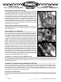
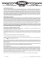
Pingel® Electric Speed Shifter Kit for H-D V-ROD MUSCLE 2009-2011
Designed for Street Use
#77805 Installation Instructions
Read all instructions thoroughly, look at photos and all components before attempting installation.
This product is not designed or intended to be used as an assistive device for any particular disability.
All the components of this Electric Speed Shifter Kit have been assembled and tested as a unit before leaving our factory and
have been found to be in working order at the time of shipping. We strongly recommend that you bench test this unit
following the directions included on the separate page. Installation of this kit requires detailed knowledge of the motorcycle
model, its electronics and mechanics. It is assumed that the installer has access to the proper tools and a working knowledge of
them, test equipment (such as a voltmeter), and factory service manuals. The following instructions must be read in their
entirety and any questions should be answered prior to attempting installation. Incorrect installation will result in damage to
Electric Speed Shifter components. If after reading the instructions you do not feel comfortable installing the kit, please find a
qualified technician to do the installation. Installation time is 2-3 hours.
Disconnect negative battery cable before attempting any
work on motorcycle.
INSTALLATION OF DUAL BUTTON HANDLEBAR CONTROL BRACKET:
Remove the left side handlebar switch housing. Loosen the clutch perch and slide
it toward the fork 7/16”. Retighten the clutch perch. Notice that the grip has a raised
portion on the end that originally fit under the handlebar switch housing; this needs
to be trimmed back to between the grip and the flange area before installing the
switch housing. See Figure #1. Note: Use a razor knife to cut the grip while it is still
mounted on the handlebar. Reinstall the handlebar switch housing as close to the
clutch perch as possible. Install the dual button handlebar control between the hand
grip and switch housing. Be certain that the grip is secure after cutting, if not,
remove it and re-glue per manufacturers specifications.
Figure 1
Route the wires from the dual button handlebar control bracket neatly along handlebar into the speedometer/tachometer area.
From there run the wire assembly under the frame towards the battery. Alongside the battery is the approximate location that
the control module will be mounted. Make sure to secure the wires along their routing with wire ties provided. Excess wire can
be coiled and hidden in the battery area.
INSTALLATION OF CONTROL MODULE AND WIRE HARNESS:
Mounting location of the control module is alongside the battery. Note: the control module is supplied with Velcro for the bottom
of the box to secure it. The large 4-pin connector coming from the control module should be connected to the large 4-pin
connector from the fused wire harness. The small 3-pin connector on the fused harness is used for the electronic engine kill
module. There are three loose wires coming from the fused wire harness; the black (negative) and large red (positive) go
directly to the battery, the small red is for switched 12v power. The large red and black wires should be cut to the shortest
length needed to reach the battery posts which will give maximum power for the Electric Speed Shifter kit. Note: leave the small
red wire as long as possible until the next step. Solder the ring terminals provided onto the cut ends of the large red and black
wires then attach the red to the positive battery post, the black will be connected to the negative at the end of the installation.
We have found that on all of our H-D motorcycles, the orange wire with the white stripe is a switched 12v power source, but you
will need to consult the service manual for your motorcycle model to be certain you are connecting to the proper wire. Cut the
small red wire to proper length and use the blue quick tab connector supplied to make this connection. (soldering is preferred).
INSTALLATION OF THE ELECTRONIC ENGINE KILL MODULE:
The electronic engine kill module should also be mounted alongside the battery and may be secured with the supplied Velcro to
install on the bottom of the box. Insert the small male plug of the electronic engine kill module into the small female plug
located on the fused wiring harness. Plug in the cable (included loose in kit) which has a four pin male rubber plug on one
end and is blank on the other end into the small female plug of the electronic engine kill module. Route the loose end of the
cable to the signal wires of the ignition coil. Secure a brown wire from the Pingel cable to each of the coil signal wires. We
have found that on all of our H-D motorcycles the blue with orange stripe wire and the yellow with blue striped wire are the
signal wires, but consult the service manual for your motorcycle model to be certain you are connecting to the correct wires.
You can use the blue quick tab connectors provided to make these connections but soldering them is preferred. Secure this
cable with the wire ties provided.
©Copyright 2014 Pingel Enterprise, Inc. All rights reserved.
No part of this publication may be reproduced without prior written permission from the publisher.
Part Number INS-77805
Rev 06102014
Page 1 of 4
INSTALLATION OF ELECTRIC SHIFT CYLINDER:
A steel shift cylinder support bracket with half of the Pingel shift cylinder clamp
is mounted to the frame. Remove the clamp from this assembly so the steel
support bracket can be painted; note the order of assembly and do not lose any
parts especially the thin shim. Use a pencil to trace an outline of the large
washer on each side of the bracket. Mask this area before painting. Failure to
mask this area may result in improper shifter operation. Do not remove any of
the grease from the bushings, it is required for smooth operation. After
painting, reinstall the clamp half using the supplied thread locker (make certain
it is installed exactly as it was prior to removal). The support bracket mounts
where the left side lower and upper frames connect. Remove the stock bolts
and install the steel shift cylinder support bracket using the two 10mm x 75mm
shcs supplied, as shown in figure 2.
INSTALLATION OF THE ELECTRIC SHIFT CYLINDER:
Install the electric shift cylinder onto the shift cylinder support bracket using the
Pingel® clamp and (2) ¼-20 x ¾” shcs. Snug the bolts for now, as adjustment
will be needed farther on.
INSTALLATION OF SHIFT ARM BRACKET:
Temporarily install the ¼-28 x 1” bhscs through the Pingel® shift arm lever, (3)
of the ¼” flat washers, the rod end of the electric shift cylinder and tightening
on the 1/4-28 lock nut. Hold the Pingel shift lever bracket on the stock shift
lever. Make sure to push the bracket all the way down towards the pivot hole
of the shift lever, holding it into place with your fingers. Slide the cylinder down
in the clamp until the rod end bottoms out in the cylinder. Mark the stock shift
arm with a piece of tape on each side of the Pingel shift arm bracket as shown
in figure 3. Note: Photo is shown with exhaust pipe removed for clarity.
Remove the 1/4-28 bhscs, washers, locknut and Pingel shift arm bracket.
Remove the stock shift lever from the motorcycle. Place the Pingel shift lever
bracket into place on the stock shift lever aligning it with the tape put on
previously. Make sure to push the bracket all the way down towards the
mounting hole of the shift lever. Insert a 9/64” drill bit through the top hole of
the Pingel shift lever bracket and turn it with your fingers to make an
indentation on the back of the stock shift lever. Center punch the top mark and
drill through the stock shift lever squarely using a 3/16” drill bit. Remove the
tape and attach the Pingel shift lever bracket to the stock shift lever using the
one of the two 10-24 x 1” bhscs with locknut. Drill through the bottom hole of
the Pingel shift lever bracket and stock shift lever squarely using a 3/16” drill bit
then insert the second 10-24 x 1” bhscs with locknut and tighten. Reinstall the
shift lever with the Pingel bracket attached onto the motorcycle. When
completed the assembly should look as shown in figure 4.
Figure 2
Figure 3
Figure 4
ADJUSTMENT OF THE ELECTRIC SHIFT CYLINDER UP/DOWN:
The next procedure may require two people. Pull and hold the shift lever to the full up shift position and while holding the rod
end in its most outward position move the shift cylinder in the clamp until the hole in the rod end aligns with the hole in the shift
arm bracket, then tighten the two bolts of the Pingel clamp. Note: You may need to roll the motorcycle back and forth to be
certain that it is fully in gear.
ADJUSTMENT OF THE ELECTRIC SHIFT CYLINDER FOR NO SHAFT BIND:
The rod end on the shift cylinder must be located in the middle of its side play left to right. If the rod end does not line up correctly,
you can either add another thin ¼” flat washer to the existing washers to move the rod end away from the shift arm lever, or
remove one of the thin flat ¼” washers to move the rod end closer to the shift arm lever. Install the ¼-28 x 1” bhscs through the
Pingel® shift arm lever, the ¼” flat washer(s), the rod end of the electric shift cylinder and tightening on the 1/4-28 lock nut, see
figure #3. This step is important because if there is any bind in the linkage system the shifter will not work correctly. Note: The
stock shift linkage lever also has some movement left to right.
ROUTING SHIFT CYLINDER CABLE:
Route the electric cable from the shift cylinder to the control module located alongside the battery. Attach the cable by pushing
the connector into the receptacle on the control module. Secure all wires away from heat and moving parts with the supplied
wire ties.
©Copyright 2014 Pingel Enterprise, Inc. All rights reserved.
No part of this publication may be reproduced without prior written permission from the publisher.
Part Number INS-77805
Rev 06102014
Page 2 of 4
COMPLETING INSTALLATION:
Your Electric Speed Shifter Kit installation should now be complete. Reconnect the negative battery cable and the shifter ground
cable. In the interest of safety this is the recommended starting procedure: To arm the electric shifter, make sure the
motorcycle is in neutral and pull in the clutch lever, then start the engine. With the clutch lever pulled in, push either button on
the handlebar control and hold it for five seconds; release the clutch lever slowly (in case the motorcycle is accidentally in
gear). The system is now turned on and will shift when either button is pressed. When the key is turned off, the power to the
control module is disengaged so this procedure must be performed every time the motorcycle is turned back on. Pull in clutch
and check shifter movement by pushing either button on the handlebar control. It will only be necessary to use the clutch when
starting, stopping and finding neutral. Upshifting and downshifting will not require the use of the clutch. The operator may use the
clutch and foot shifter manually without harm to any components.
TESTING ENGINE KILL MODULE:
Unplug the electric shift cylinder from the control module. Take note of the positions of the dipswitches on the electronic engine kill
module. Position all three of the dipswitches to the off position. Pull in the clutch lever (hold it in until the end of the test), start the
motorcycle and put it into neutral. Arm the system by holding one of the buttons for five seconds as explained in the previous
instructions. Rev the engine to approximately 1500-2000 rpm and hold it there, push either button and listen for the engine to miss
as one of the buttons is pushed. If the miss is not present, your kill is not correctly installed. Recheck your connections, making
certain all wires are properly connected per the wiring instructions. Reconnect the shift cylinder to the control module after verifying
the kill module is working properly. Return the dipswitches on the kill module to the position noted before the test was started.
Be certain that all of the round connectors are properly coupled and tight. If the motorcycle is not shifting or the kill
module is not working, check that these plugs are properly seated and that the internal connector pins are making
good contact with their sockets (i.e. no pins are bent). Also, check that one of the pins has not moved off to the side of
their respective sockets when pushing the plug together.
ADJUSTING KILL TIME AND ADJUSTING CYLINDER:
The factory preset kill time may not be correct for every application. Kill adjustment is set by moving the dipswitches on the
electronic engine kill module to the desired time on the chart.
If a more aggressive shift is desired, you can go shorter one setting at a time until the shift is missed, then back to the last setting
that allowed the motorcycle to shift. If you desire a more low performance, smoother shift or if the motorcycle goes into a false
neutral or stays in the same gear, you can adjust the kill time by going longer one setting at a time until the desired shift is
achieved.
The preset kill time should be acceptable for most street riding conditions.
For performance riding or racing it may require a shorter kill time setting then the preset time.
If shifting up or down is not achieved, you may need to adjust the up/down positioning of the cylinder and/or readjust the cylinder
for no bind as explained earlier in the instructions.
Note: If the motorcycle misses shifts or goes into a false neutral, the cause may not be the Electric Speed Shifter kit. This
condition may be caused by an internal problem in the transmission that requires the replacement of the actuator and drum kit
(H-D part# 35017-01K) and the shift forks. This problem was discovered on our 2003 V-Rod, replacing these components has
resolved the problem.
After fine adjustment has been made remove each clamp bolt and apply thread locker to the end threads, but remove
only one clamp bolt at a time so as not to lose your adjustment of the shift cylinder location.
Helpful Operating Tips:
Here is an example of what we found works for us: when upshifting at whatever your shift point RPM is (2000 – 6500) do not
drop the RPM to make a shift happen, this will not help. RPM must be kept up to make a shift happen. When traveling at lower
speeds, twist the throttle on slightly when hitting the shift button, to make a smoother shift. When downshifting, if you keep the
rpm’s between 1400-2000 you may be able to downshift without wicking the throttle, just a push of the button. If not, a slight
crack of the throttle helps to smoothly go into lower gears. Our testing team has found that downshifting works best when
shifting just under the following mph: 4th gear at 40mph, 3rd gear at 30mph, 2nd gear at 20mph and 1st gear at 10mph. Note:
Downshifting on a corner while leaning the bike may cause loss of control.
Note: In the wire harness we have installed one 40-amp fuse for constant power. A spare 40-amp fuse is also supplied.
©Copyright 2014 Pingel Enterprise, Inc. All rights reserved.
No part of this publication may be reproduced without prior written permission from the publisher.
Part Number INS-77805
Rev 06102014
Page 3 of 4
Prolonged repeated operation of the shifter (actuating the shifter repeatedly in rapid succession beyond normal use)
can discharge the motorcycle battery and damage the shift cylinder and/or the control module. The normal battery
takes 30-60 minutes to recharge after starting the motorcycle so use the shifter sparingly in this time.
This unit is not waterproof. Do not subject it to pressure washing or extreme moisture.
Installation of Electric Speed Shifter Kit still maintains OEM Shifting.
If you have any questions please call 608-339-7999
Thank you for purchasing a Pingel Enterprise, Inc. product.
Items included: H-D V-ROD MUSCLE
1 - Electronic engine kill module
1 - Electric shift cylinder
1 - Electric shift cylinder support bracket with
cylinder clamp (threaded)
2 - Ring terminals
3 - Blue quick tab connector
1 - Cylinder clamp (thru-holes)
10 - Wire ties
2 - 10mm x 1.50mm x 75mm zinc shcs
1 - Tube thread locker
1 - Fused wiring harness
1 - 40-amp fuse
1 - 1” handlebar two piece dual button control assembly
1 - Electronic engine kill module
1 - Control module
1 - Electronic engine kill module wire leads to coil
1 - ¼”-28 x 1” button head
1 - Pingel shift arm lever
4 - ¼” washer
2 - 10-24 x 1” stainless button head socket cap screw
1 - ¼”-28 locknut
2 -
10-24 half width locknut
Dear Valued Customer,
Pingel Enterprise, Inc. would like to take this opportunity to thank you for purchasing one of our Electric Speed Shifter Kits.
We would also like to know what you think of the product and how your installation went. Your assistance can help us overcome any
technical issues that other installers may experience. You can reach us toll free at 1-888-474-6435 or email us at [email protected].
We are also requesting photos of your installation.
Your photos may be selected for publication in the Pingel catalog or at
www.pingelonline.com. Photos may be submitted by emailing them to [email protected]. When submitting a photo, please
include the motorcycle model and year.
Thank you again for your purchase!
LIMITED WARRANTIES/LIABILITIES
Pingel E nterprise, Inc . assumes n o res ponsibility or l iability f or damage or in jury of a ny k ind arising out of t he use or m isuse of a ny pro ducts. Pinge l
Enterprise, Inc.’s sole responsibilities with respect to products sold are to provide the following limited warranty:
Pingel Products: Pingel Enter prise, Inc. warrants to the ori ginal purchaser that th e product shall be fre e from defects in pa rts and work manship under
normal use for 3 0 days from date o f purchase. Pingel Enterprise, Inc’s obligation under this warranty is limited to the re pair or replacement of any part
found t o be de fective whe n r eturned p ostpaid to the factory. Th e product mus t be ret urned with ev idence of da te and p lace of p urchase, an d d etailed
description of the probl em. The w arranty wil l no t a pply if t he product has be en i nstalled i ncorrectly, re paired, or damaged by modification, m isuse,
negligence or accident. The repair or replacement of such part, as needed, is your sole and exclusive remedy. No refunds will be given. Pingel Enterprise,
Inc. mak es no other warra nty, ex pressed or im plied with res pect to its produc ts and s pecifically dis claims any imp lied warrant ies of m erchantability or
fitness of any product for a particular purpose and except as herewith stated assumes no liability with respect to the product.
Dispute Resolution: All disputes, claims or controversies of any kind that may arise between you and Pingel Enterprise, Inc. shall be brought in the state
court located in A dams County, Wisconsin. You a gree that th e sole venue and jurisdiction for s uch disputes shall be th e above named court and hereby
submit to the jurisdiction of that court.
THANK YOU for purchasing a PINGEL ENTERPRISE, INC., product. View our entire product line at www.pingelonline.com
©Copyright 2014 Pingel Enterprise, Inc. All rights reserved.
No part of this publication may be reproduced without prior written permission from the publisher.
Part Number INS-77805
Rev 06102014
Page 4 of 4