1
TM
11–6625–2781–14–6
TECHNICAL MANUAL
OPERATOR’S, ORGANIZATIONAL, DIRECT SUPPORT, AND
GENERAL SUPPORT MAINTENANCE MANUAL INCLUDING
REPAIR PARTS AND SPECIAL TOOLS LIST
FOR
FILTER, VARIABLE F–1414/U(HP–8445B)
(NSN
H E A D Q U A R T E R S ,
6625-00-253-4833)
D E P A R T M E N T
O F
T H E
A R M Y
30 NOVEMBER 1978
WARNING
DANGEROUS VOLTAGES EXIST IN THIS EQUIPMENT
DON’T TAKE CHANCES!
This manual contains copyrighted material reproduced by permission of the Hewlett-Packard Company. All rights reserved.
TM 11-6625-2781-14-6
HEADQUARTERS
DEPARTMENT OF THE ARMY
WASHINGTON, DC, 30 November 1978
TECHNICAL MANUAL
NO. 11–6625-2781-14-6
OPERATOR’S, ORGANIZATIONAL, DIRECT SUPPORT, AND
GENERAL SUPPORT MAINTENANCE MANUAL INCLUDING
REPAIR PARTS AND SPECIAL TOOLS LIST
FOR
FILTER,
VARIABLE
F–1414/U(HP-8445B)
(NSN 6625-00-253-4833)
REPORTING OF ERRORS
You can improve this manual by recommending improvements using DA Form 2028-2 located in
the back of the manual. Simply tear out the self-addressed form, fill it out as shown on the sample, fold
it where shown, and drop it in the mail.
If there are no blank DA Forms 2028-2 in the back of your manual, use the standard DA Form
2028 (Recommended Changes to Publications and Blank Forms) and forward to the Commander, US
Army Communications and Electronics Materiel Readiness Command, ATTN: DRSEL-ME-MQ,
Fort Monmouth, NJ 07703.
In either case a reply will be furnished direct to you.
This manual is an authentication of the manufacturer’s commercial literature which, through usage, has been found to cover the data required to operate and maintain this equipment. The manual was not prepared in accordance with military specifications; therefore, the format has not been structured to consider categories of maintenance.
TABLE OF CONTENTS
Page
0-1
INTRODUCTION
SECTION 0–1 Scope . . . . . . . . . . . . . . . . . . . . . . . . . . . . . . . . . . . . . . . . . . . . . . . . . . . . . . . . . . . . . . . . . . . . . . . . . . . . . . . . . . . . . . . . . . 0-1
0–2 Indexes of Publications . . . . . . . . . . . . . . . . . . . . . . . . . . . . . . . . . . . . . . . . . . . . . . . . . . . . . . . . . . . . . . . . . . . . . . . . . . . . . 0-1
0-3 Forms and Records . . . . . . . . . . . . . . . . . . . . . . . . . . . . . . . . . . . . . . . . . . . . . . . . . . . . . . . . . . . . . . . . . . . . . . . . . . . . 0 - 1
0-4 Administrative Storage . . . . . . . . . . . . . . . . . . . . . . . . . . . . . . . . . . . . . . . . . . . . . . . . . . . . . . . . . . . . . . . . . . . . . . . . . 0-1
0-5 Destruction of Army Electronics Materiel . . . . . . . . . . . . . . . . . . . . . . . . . . . . . . . . . . . . . . . . . . . . . . . . . . . . . . . . . . . . . . . . . 0-1
0-6 Reporting Equipment Improvement Recommendations (EIR) . . . . . . . . . . . . . . . . . . . . . . . . . . . . . . . . . . . . . . . . . . . . . . . 0-1
0–7 Items Comprising an Operable Equipment . . . . . . . . . . . . . . . . . . . . . . . . . . . . . . . . . . . . . . . . . . . . . . . . . . . . . . . . . . . . . . . . 0–1
This manual supersedes TM 11-6625-2865-14&P, 26 January 1978.
i/(ii blank)
TM 11-6625-2781-14-6
Modl 8445B
CONTENTS
Page
Section
GENERAL INFORMATION . . . . . . .
I
II
III
1-1
.
.
.
.
.
.
.
.
.
.
.
.
.
.
.
1-1
1-1
1-1
1-1
1-1
1-1
1-3
1-4
1-4
1-4
1-5
1-5
1-5
1-6
1-6
INSTALLATION . . . . . . . . . . .
2-1. Introduction . . . . . . . . . .
2-3. Initial Inspection . . . . . . . . .
2-5. Preparation for Use . . . . . . . .
Power Requirements. . . . . . .
2-6.
Line Voltage and Fuse Selection . . .
2-8.
Power Cable . . . . . . . . .
2-10.
Mating Connectors . . . . . . .
2-12.
2-14.
Operating Environment. . . . . .
Installation Instructions. . . . . .
2-17.
2-19.
Bench Operation . . . . . . . .
2-21.
Rack Mounting . . . . . . . .
2-23. Modifications Required. . . . . . .
2-24.
Display Sections . . . . . . . .
2-26.
8555A RF Section . . . . . . .
2-28. Storage and Shipment . . . . . . .
Environment . . . . . . . . .
2-29.
Packaging . . . . . . . . .
2-31.
2-1
2-1
2-1
2-1
2-1
2-1
2-2
2-2
2-2
2-2
2-2
2-2
2-3
2-3
2-3
2-4
2-4
.2-4
OPERATION . . . . . . . . . . . .
3-1. Introduction . . . . . . . . . .
3-3. Spectrum Analyzer Preelection . . . .
3-8. Recommended Mixing Modes. . . . .
3-10. Preselector Tracking. . . . . . . .
3-12. Preselector Bandwidth . . . . . . .
3-14. Panel Features. . . . . . . . . .
3-16. Operator’s Checks . . . . . . . .
3-18. Operating Instructions . . . . . . .
3-20. Operator’s Maintenance . . . . . .
Fuses . . . . . . . . . . . .
3-22.
Air Filter . . . . . . . . .
3-24.
3-26. Fan . . . . . . . . . . ..
Lamp Replacement . . . . . . .
3-28.
3-1
3-1
3-1
3-1
3-2
3-2
3-2
3-3
3-3
3-3
3-3
.3-3
3-3
3-3
1-1.
1-7.
1-9.
1-10.
1-12.
1-14.
1-19.
1-24.
1-27.
1-29.
1-38.
1-40.
1-42.
1-44.
1-46.
Introduction . . . . . . . . .
Specifications . . . . . . . . .
Safety Considerations . . . . . .
General . . . . . . . . . .
Operation . . . . . . . . .
Service . . . . . . . . . .
Instruments Covered by Manual . . .
Option 003 Instruments Only. . .
Description . . . . . . . . . .
Options . . . . . . . . . . .
Accessories Supplied. . . . . . .
Equipment Required but not Supplied.
Equipment Available. . . . . . .
. . . . . .
Deleted
Recommended Test Equipment . . .
Page
Section
IV
V
PERFORMANCE TESTS . . . . . . . .
4-1. Introduction . . . . . . . . . .
4-4. Test Record . . . . . . . . . .
4-6. Front Panel Checks . . . . . . . .
4-8. Preset Adjustments . . . . . . . .
4-10. Performance Tests . . . . . . . .
4-15. Abbreviated Performance Test . . . .
4-17. Out-of-Band Rejection Test . . . . .
4-18. Low-Pass Filter Insertion Loss Test(Omit
for Instruments with Option 004) . .
4-19. YIG Filter Insertion Loss Test . . . .
4-20. Limiting Level Test . . . . . . . .
ADJUSTMENTS . . . . . . . . .
5-1. Introduction . . . . . . . .
5-3. Equipment Required . . . . .
5-5. Factory Selected Components . .
5-7. Related Adjustments . . . . .
5-9. Location of Adjustments . . . .
5-11. Power Supplies Adjustment . . .
5-12. YIG or DPM Pre-Driver Adjustment.
5-13. YIG Driver Adjustment. . . . .
5-14. Digital Panel Meter Adjustment
(Option 003) . . . . . . .
5-15. Insertion Loss Chart for
Replacement YIG . . . . ..
.
.
.
.
.
.
.
.
.
.
.
.
.
.
.
.
.
.
4-1
4-1
4-1
4-1
4-1
4-2
4-2
4-2
4-5
4-7
4-9
5-1
5-1
5-1
5-2
5-2
5-2
5-2
5-3
5-6
. . 5-8
. . . . 5-10
VI
DELETED
VII
MANUAL CHANGES . . . . . . . . . 7-1
7-1. Introduction . . . . . . . . . . 7-1
7-5. Manual Change Instructions . . . . . 7-1
VIII SERVICE . . . . . . . . . . . ..
8-1. Introduction . . . . . . . . . .
8-3. Assembly Service Sheets . . . . . .
8-5. Principles of Operation . . . . . . .
8-7. Troubleshooting . . . . . . . . .
8-9. Recommended Test Equipment . . . .
8-11. Repair . . . . . . . . . . ..
8-12.
Rigid Cables . . . . . . . . .
Cleaning Switches . . . . . . .
8-14.
8-16. General Service Hints . . . . . . .
Etched Circuit Boards . . . . . .
8-17.
8-19.
Component Replacement . . . . .
8-1
8-1
8-1
8-1
8-1
8-1
8-1
8-1
8-1
8-2
8-2
8-4
iii
TM 11-6625-2781-14-6
Model 8445B
CONTENTS(Cont’d)
Page
Section
8-21. General Service Information . . . . .
Transistors and Diodes . . . . . .
8-22.
Operational Amplifiers . . . . . .
8-28.
8-31. Electrical Maintenance . . . . . . .
8-33. Mechanical Maintenance . . . . . .
Page
Section
APPENDICES
8-5
8-5
8-5
8-6
8-6
A Delete
B Service Note No. 8555A-1
Preselector DPM Modification
C References . . . . . . . . . . .
D Maintenance Allocation Chart . .
E Difference Data Sheets . . . . .
ILLUSTRATIONS
Page
Figure
1-1.
1-2.
1-3.
2-1.
2-2.
Mode18445B and Accessories Supplied . .
Serial Number Plate. . . . . . . . .
RF Interconnect Cable . . . . . . . .
Line Voltage Selection . . . . . . . .
Power Cable HP Part Numbers Versus
Mains Plugs Available . . . . . . .
.
.
.
.
1-0
1-4
1-6
2-1
Figure
B-1
C-1
D-1
E-1
Page
8-2. Examples of Diode and Transistor
Marking Methods . . . . . . . . . . 8-7
8-3. Operational Amplifier Equivalent Circuit . . . 8-8
8-4. Top View of 8445B With Option 002 Panel
8-10
Switches and Controls . . . . . . .
. 2-2
2-3. Preparation for Rack Mounting . . . . . . 2-3
3-1. Spectrum Analyzer Tuning Curves
and Responses. . . . . . . . . . . 3-2
3-2. Typical 3-dB Yig Filter Passband Display
at 4 GHz and with a 10 MHz/DIV sweep . . 3-2
3-3. 8445B Controls, Connectors and Indicators . . 3-4
3-4. Low-Pass Filter Operation, 10 MHz to 1.8 GHz . 3-7
3-5. 1.8 to 18 GHz YIG-Tuned Filter Operation . .3-10
3-6. Power Lamp Replacement. . . . . . . .3-13
4-1. Out-of-Band Rejection Test Setup . . . . . 4-3
4-2. Insertion Loss Test Setup, Dc-1.8 GHz . . . 4-5
4-3. Insertion Loss Test Setup, 1.8-18 GHz . . . 4-7
4-4. YIG Filter Signal Compression Test Setup . .4-10
5-1. Power Supply Adjustment Test Setup . . . . 5-2
5-2. Pre-Driver Adjustment Test Setup . . . . . 5-4
5-3. YIG Driver Adjustment Test Setup . . . . . 5-7
5-4. Digital Panel Meter Adjustment Test Setup . . 5-9
Remote Amplifier Adjustment Test Setup
(Figure 5-3) (P/O CHANGE C) . . . . . 7-2
7-2. Partial Schematic correction for
Service Sheet 4. (P/O CHANGE C) . . . . 7-4
7-3. Partial schematic correction for
Service Sheet 5. (P/O CHANGE C) . . . . 7-4
7-1.
8-1. Transistor Characteristics and Biasing . . . . 8-6
iv
8-5. Block Diagram of Standard 8445B With
Option 003 Circuits Unshaded . . . . .8-11
8-6. Block Diagram of 8445B With
Option 002 Circuits Unshaded . . . . .8-11
8-7. Troubleshooting Flow Diagram . . . . . .8-13
8-8. Comprehensive Block Diagram Including
Options 002 and 003. . . . . . . . .8-15
8-9. Al Predriver Assembly of 8445B
(Except Option 003) . . . . . . . .8-17
8-10. YIG Predriver Schematic Diagram . . . . .8-17
8-11. Top View of 8445B With Option 003
Including Digital Display A7 . . . . . .8-18
8-12. Top View of 8445B, Option 003
With A7 Removed . . . . . . . . .8-18
8-13. Al Predriver Assembly of 8445B (Option 003) .8-18
8-14. A7 Display Board (See Option 003
Supplement For Details) A7 8445B. . . .8-14
8-15. DPM Predriver Schematic Diagram . . . . .8-19
8-16. A3 YIG Driver Assembly . . . . . . . .8-21
8-17. P/O YIG Driver Schematic Diagram. . . . .8-21
8-18. A2 Power Supply and Filter
Switching Assembly . . . . . . . . .8-23
8-19. Remote and Manual Control Amplifiers/
Switching Circuit Schematic Diagram . . .8-23
8-20. A2 Power Supply and Filter
Switching Assembly . . . . . . . . .8-25
8-21. Power Supply and Power Line Module
Schematic Diagram . . . . . . . . .8-25
8-22. Adjustment Controls . . . . . . . . .8-27
8-23. Option 003 Al Adjustment Controls . . . .8-27
8-24. Over all Schematic Diagram . .8-29
TM
Model 8445B
11-6625-2781-14-6
TABLES
Table
1-1. 8445B Specifications . . . .
1-2. Typical Operating Characteristics
1-3. Accessories Supplied. . . . .
1-4. RF Interconnect
Cable Information . . . .
1-5. Test Equipment and Accessories .
2-1. Model 8445B Mating Connectors.
2-2. Modification of Display Sections
for Preselector Compatibility .
3-1. 8555A Frequency Ranges and
Recommended Mixing Modes.
4-1. Performance Test Record . . .
Page
. . . . . 1-2
. . . . . 1-2
. . . . . 1-5
. . . . . 1-6
. . . . . 1-7
. . . . . 2-3
. . . . . 2-4
. . . . . 3-3
. . . . . 4-12
Table
Page
5-1. Adjustable Controls and
Factory Selected Component . . . . . . 5-1
5-2. Insertion Loss Table . . . . . . . . . .5-10
7-1.
8-1.
Serial Number Change History . . . . . . 7-1
Foldouts-Assemblies-Photographs
Cross-referenced . . . . . . . . . . 8-2
8-2. Schematic Diagram Notes . . . . . . . . 8-3
8-3. Etched Circuit Soldering Equipment . . . . 8-4
8-4. Relay Operations by Band Code Bits . . . .8-16
V
TM
11-6625-2781-14-6
SECTION 0
INTRODUCTION
0-1. Scope
This manual contains instructions for the operation,
organizational maintenance, and general support
maintenance of Filter, Variable F-1414/U
hereinafter referred to as Hewlett-Packard Model
HP-8445B Automatic Preselector.
NOTES
Appendix C contains a list of applicable
references, Appendix D contains the
maintenance allocation chart (MAC).
No direct support maintenance is authorized for this equipment.
0-2. Indexes of Publications
a. DA Pam 310-4. Refer to latest issue of DA Pam
310-4 to determine whether there are new editions,
changes, or additional publications pertaining to the
equipment.
b. DA Pam 310-7. Refer to DA Pam 310-7 to
determine whether there are modification work
orders (MWO’S) pertaining to the equipment.
0-3. Forms and Records
a. Reports of Maintenance of Unsatisfactory
Equipment. Maintenance forms, records, and reports
which are to be used by maintenance personnel at all
levels are listed in and prescribed by TM 38-750.
b. Report of Packaging and Handling Deficiencies.
Fill out and forward DD Form 6 (Packaging Improvement Report) as prescribed in AR
700-58/NAVSUPINST 4030.29/AFR 71-13/MCO
P4030.29A, and DLAR 4145.8.
c. Discrepancy in Shipment Report (DISREP) (SF
361). Fill out and forward Discrepancy in Shipment
Report (DISREP) (SF 361) as prescribed in AR
55-38/NAVSUPINST 4610.33 B/AFR 75-18/MCO
P4610.19C, and DLAR 4500.15.
0-4. Administrative Storage
Before placing the F-1414/U in temporary storage
(90 days), determine the serviceability of the equipment by performing the maintenance procedures
described in paragraphs 8-32 and 8-34.
0-5. Destruction of Army Electronics Materiel.
Destruction of Army electronics materiel to prevent
enemy use shall be in accordance with TM
750-244-2.
0-6. Reporting Equipment Improvement
Recommendations (EIR)
EIR's will be prepared using Standard Form 368,
Quality Deficiency Report. Instructions for preparing
EIR’s are provided in TM 38-750, The Army
Maintenance Management System. EIR's should be
mailed direct to Commander, US Army Communications and Electronics Materiel Readiness
Command, ATTN: DRSEL-ME-MQ, Fort Monmouth, NJ 07703. A reply will be furnished direct to
you.
0-7. Items Comprising an Operable Equipment
Filter, Variable F-1414/U comprises an operable
equipment.
0-1
Mode18445B
TM 11-6625-2781-14-6
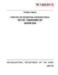
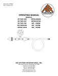
Figure 1-1. Mode1 8445B and Accessories Supplied
1-0
TM 11-6625-2781-14-6
Mode1 8445B
SECTION I
GENERAL INFORMATION
1-1. INTRODUCTION
1-2. This manual contains all information required to install, operate, test, adjust and service the
Hewlett-Packard Model 8445B Automatic Preselector. This section covers instrument identification,
description, options, accessories, specifications and
other basic information.
1-3. Figure 1-1 shows the Hewlett-Packard Model
8445B Automatic Preselector with Option 002
(manual tuning controls) and Option 003 (digital
readout of center frequency).
1-4. The various sections in this manual provide
information as follows:
SECTION II, INSTALLATION, provides information relative to incoming inspection,
power requirements, mounting, packing and
shipping, etc.
SECTION III, OPERATION, provides information relative to operating the instrument.
SECTION IV, PERFORMANCE TESTS, provides information required to ascertain that
instrument is performing in accordance with
published specifications.
SECTION V, ADJUSTMENTS, provides information required to properly adjust and
align the instrument after repairs are made.
SECTION VI, REPLACEABLE PARTS, provides ordering information for all replaceable
parts and assemblies.
SECTION VII, MANUAL CHANGES, normalIy will contain no relevant information in
the original issue of a manual. This section is
reserved to provide back-dated and up-dated
information in manual revisions or reprints.
SECTION VIII, SERVICE, includes all information required to service the instrument
be kept with the instrument for use by the operator.
Also included with the manual is an Overall
Schematic Diagram. Additional copies of both the
Operating Information Supplement and the Overall
Schematic Diagram can be ordered separately
through your nearest Hewlett-Packard office. The
part numbers are listed on the title page of this
manual.
1-6. Also listed on the title page of this manual is a
Microfiche part number. This number can be used to
order 4 x 6-inch microfilm transparencies contains
up to 60 photoduplicates of the manual pages. The
Microfiche package also includes the latest Manual
Changes supplement and all pertinent Service
Notes.
1-7. SPECIFICATIONS
1-8. Specifications for the instrument are listed in
Table 1-1. These are the performance standards the
instrument is tested against. A list of typical operating characteristics is provided in Table 1-2. They are
included as additional information only; they are
not specifications.
1-9. SAFETY CONSIDERATIONS
1-10. General
1-11. This is an International Electrotechnical
Commission (IEC) Safety Class I instrument, designed and tested according to IEC Publication 348,
“Safety Requirements for Electronic Measuring
Apparatus.” It has been supplied in safe conditon.
1-12. Operation
1-13. BEFORE APPLYING POWER, make sure
the ac input to the instrument is set for the available
ac line voltage, that the correct fuse is installed
(Figure 2-1), and that all normal safety precautions
have been taken.
1-14. Service
1-5. Supplied with this manual is an Operating
Information Supplement. The Supplement is a copy
of the first three sections of the manual, and should
1-15. Although the instrument has been designed
in accordance with international safety standards,
1-1
Mode18445B
TM 11-6625-2781-14-6
Table 1-1. 8445B Specifications
SPECIFICATIONS
Frequency Range: Dc to 1.8 GHz Low-Pass Filter.
1.8 to 18 GHz Tracking Filter.
Out-of- Band Rejection: For YIG tuned filterl GHz
from center of passband >70 dB.
Digital Frequency Readout (Option 003):
Limiting Level: > +5 dBm (Maximum input level
for < 1 dB signal compression ).
Resolution: 1 MHZ
Accuracy: 0.01 to 1.0 GHz: ±6 MHz
1.0 to 4.0 GHz: ±8 MHz
4.0 to 18.0 GHz: ±0.2 %
Burnout Level: > +20 dBm.
Hysteresis: < 25 MHz.
Tuning Linearity: < ±10 MHz.
Insertion Loss:
*Low-Pass Filter deleted with Option 004.
Table 1-2. Typical Operating Characteristics
Table 3-1
paragraph 5-15
1-2
Model 8445B
the information, cautions, and warnings in this
manual must be followed to ensure safe operation
and to keep the instrument safe. Service and adjustments should be performed only by qualified
service personnel.
1-16. Adjustment or repair of the opened instrument with the ac power connected should be avoided
as much as possible and, when inevitable, should be
performed only by a skilled person who knows the
hazard involved.
1-17. Make sure only fuses of the required current
rating and type (normal blow, time delay, etc.) are
used for replacement. Do not use repaired fuses or
short circuit the fuse holders.
1-18. Whenever it is likely that the protection has
been impaired, make the instrument inoperative
and secure it against any unintended operation.
TM 11-6625-2781-14-6
set to the voltage of the ac power source.
BEFORE SWITCHING ON THIS INSTRUMENT, make sure that all devices connected
to the instrument are connected to the protective earth ground.
BEFORE SWITCHING ON THIS INSTRUMENT, make sure the line power (mains) plug
is connected to a three-conductor line power
outlet that has a protective (earth) ground.
(Grounding one conductor of a two-conductor
outlet is not sufficient.)
BEFORE SWITCHING ON THIS INSTRUMENT, make sure the ac line fuse is of the required current rating and type (normal-blow,
slow-blow, etc.)
1-19. INSTRUMENTS COVERED BY
MANUAL
If this instrument is to be energized through an
autotransformer (for line voltage variation),
make sure the common terminal is connected
to the earthed pole of the power source.
BEFORE SWITCHING ON THE INSTRUMENT, the protective earth terminals of the
instrument must be connected to the protective
conductor of the (mains) power cord. The mains
plug shall only be inserted in a socket outlet
provided with protective earth contct. The protection must not be negated by using an extension cord (power cable) without a protective
grounding conductor.
Any interruption of the protective (grounding)
conductor, inside or outside the instrument, or
disconnection of the protective earth terminal
is likely to make this instrument dangerous.
Intentional interruption of the earth ground is
prohibited.
Servicing this instrument often requires that
you work with the instrument’s protective covers removed and with ac power connected. Be
very careful; the energy at many points in the
instrument may, if contacted, cause personal
injury.
BEFORE SWITCHING ON THIS INSTRUMENT, make sure the instrument’s ac input is
1-20. Attached to the instrument is a serial
number plate (Figure 1-2). The serial number is in
two parts. The first four digits and the letter are the
serial number prefix; the last five digits are the
suffix. The prefix is the same for all identical instruments; it changes only when a change is made to
the instrument. The suffix, however, is assigned
sequentially and is different for each instrument.
The contents of this manual apply to instruments
with the serial number prefix(es) listed under SERIAL NUMBERS on the title page.
1-21. An instrument manufactured after the
printing of this manual may have a serial number
prefix that is not listed on the title page. This unlisted serial number prefix indicates the instrument
is different from those described in this manual. The
manual for this newer instrument is accompanied
by a yellow Manual Changes supplement. This supplement contains “change information” which tells
you how to adapt the manual to the newer instrument.
1-22. In addition to change information, the supplement may contain information for correcting errors in the manual. To keep this manual as current
and accurate as possible, Hewlett-Packard recommends that you periodically request the latest Manual Changes supplement. The supplement for this
manual is identified with this manual’s print date
and part number, both of which appear on the manual title page. Complimentary copies of the supplement are available from Hewlett-Packard.
1-3
Model 844513
TM 11-6625-2781-14-6
The YIG filter maybe tuned by external sweep voltage or manually tuned by front panel controls (Option 002). A Digital Panel Meter (Option 003) normally indicates the Spectrum Analyzer center frequency. In remote or manual modes, the indicated
frequency is that to which the YIG filter is tuned.
1-23.
1-29. OPTIONS
Figure 1-2. Serial Number Plate
1-24. Option 003 Instruments Only
1-25. When an 8445B, Option 003 instrument is
ordered (see paragraph 1-33), this manual, an Option 003 Supplement, and an A7 Digital Panel
Meter (HP Model 34740A) manual are shipped with
the instrument.
1-26. This manual provides necessary references
to either the supplement or the A7 DPM Assembly
(34740A) manual. The supplement includes partial
schematics, tables, and explanations of interconnections and/or modifications made to the Digital Panel
Meter which make it compatible to the 8445B.
1-27. DESCRIPTION
1-28. The Model 8445B Automatic Tracking Preselector is designed to complement the Model 8555A
Spectrum Analyzer RF Section. The Standard Preselector covers the frequency range of dc to 18 GHz.
When used with the 8555A Spectrum Analyzer, the
Preselector functions to reduce or eliminate signal
intermodulation, in addition to multiple and spurious responses. The Standard Preselector has a fixed
frequency low-pass filter for the dc to 1.8 GHz frequency range, and a voltage tuned filter, using a
YIG (yttrium-iron-garnet) crystal as a resonant tuning circuit in the RF signal path for the frequency
range of 1.8 to 18 GHz. When used with the
8555A/8552/140 Spectrum Analyzer system, the
YIG filter is a swept selective filter that tracks the
frequency of the analyzer as the analyzer sweeps
across its selected range. The YIG filter is electronically tuned by sweep voltage and band code signals
from the analyzer. In addition to its primary function as a Preselector, the YIG filter may be used as a
manually or electronically tuned bandpass filter.
1-4
1-30. The Standard 8445B. An Automatic Preselector consisting of a YIG-tuned tracking filter
operating between 1.8 and 18 GHz, and a dc to 1.8
GHz low-pass filter. The input and output ports of
the instrument are Type N coaxial connectors. Included is an HP 11670L rigid coaxial cable for connection of the 8445B output to an 8555A spectrum
analyzer when the preselector is mounted above the
8555A with a joining bracket kit. For other mounting configurations, order 8445B Option 005 to delete
the 11670L. Then select the appropriate cable indicated in Table 1-4.
1-31. Option 001. The standard Type N input
and output port connectors are replaced by Precision
APC-7 connectors. An HP 11670M interconnect
cable (with APC-7 connectors) is included in place of
the HP Number 11670L cable. An 8445B Option 001
must be used with an 8555A Option 001 which has
an APC-7 RF Input connector. (An APC-7 terminated RF interconnect cable can be ordered from
Table 1-4. Order Option 005 to delete the standard
Type N interconnect cable.)
1-32. Option 002. A front panel MODE switch
and two MANUAL TUNE controls are added to the
Automatic Preselector to provide selection of manual tuning, automatic tuning, and remote tuning of
the YIG-tuned filter, or substitution of a 1.8 MHz
low-pass input filter.
1-33. Option 003. A digital readout of the center
frequency of the spectrum analyzer is displayed by a
digital panel meter (DPM) on the front panel of the
preselector. The DPM indictes the frequency of the
YIG-tuned filter when voltage fed to the REMOTE
input BNC connector is used to control the YIG.
1-34. Option 004. The 1.8 GHz low-pass filter is
deleted.
1-35. Option 005. The HP 11670L rigid RF Interconnect cable is deleted.
1-36. Option 100. Includes a modification kit for
certain Model 140 mainframes (see Paragraph 2-22
and Table 2-2) to make these displays compatible
TM 11-6625-2781-14-6
with the 8445B. It adds an Auxiliary B output jack
to the display mainframe.
1-40. EQUIPMENT REQUIRED BUT NOT
SUPPLIED
1-37. Option 200. Includes a modification kit for
1-41. The Automatic Preselector is intended for
use with the 8555A Spectrum Analyzer System.
This includes an 8555A RF Section, an 8552 series
IF Section, and a 140 or 141 series Display Section.
certain Model 140 mainframes (see Paragraph 2-22
and Table 2-2) to make these displays compatible
with the 8445B. It adds Auxiliary A and B output
jacks to the display mainframe.
1-42. EQUIPMENT AVAILABLE
1-38. ACCESSORIES SUPPLIED
1-39. Table 1-3 lists the accessories supplied with
the Preselector. The accessories supplied are for a
standard installation which provides for the Preselector to be mounted on an 8555A Spectrum
Analyzer and fastened with a joining racket kit. A
different mounting installation will require a different RF cable to connect between the Preselector
output and the Spectrum Analyzer input (Figure
1-3). The power cable supplied with the instrument
is selected at time of shipment. Selection is based on
shipping destination. Figure 2-2 illustrates the different power cable connectors that are currently
available.
1-43. The rigid RF Interconnect cable used to couple a Preselector to a Spectrum Analyzer is illustrated in Figure 1-3. Standard Preselectors are
made to operate above the Spectrum Analyzer. The
possible mounting configurations, connector types,
dimensions and part numbers are indicated in Table
1-4. For information regarding RF Interconnect cables used when the Preselector is mounted BELOW
the Spectrum Analyzer, contact your local
Hewlett-Packard Sales Office. A Rack Mounting
Kit is available to install the instrument In a 19-inch rack.
Rack Mounting
Kits may be obtained through your nearest
Hewlett-Packard Office by ordering HP
Part Number 5060-8739.
Table 1-3. Accessories Supplied
Name
HP Part Number
*
Description
Line Power Cable
7- 1/2 feet, 3-wire Ac, Line Cord
11670L**
RF Interconnect Cable
Rigid Coaxial Cable. Connects Preselector
RF output to Spectrum Analyzer RF
Input. Type N connectors.
08445-60007
Interconnect Cable
20-inch Control Cable, interconnects
Preselector with Spectrum Analyzer.
2110-0012
Fuse
0.5A - 220/240 Vac
5060-8543
Joining Bracket Kit
Hardware and parts for strapping
Preselector to Spectrum Analyzer.
*See paragraph 2-10 end Figure 2-2.
**See paragraph 1-35 and Figure 1-3; item not supplied with Option 005.
1-5
TM 11-6625-2781-14-6
Mode18445B
Figure 1-3. RF Interconnect Cable
Table 1-4. RF Interconnect Cable Information
Preselector Analyzer
Connector
Type
Dimension of
“X”, Figure 1-3
Inches
HP Part
Number
Cm
With feet on Preselector
N
4.72
11.99
11670C
With feet on Preselector
APC-7
4.72
11.99
11670D
Rack Mounted
N
4.58
11.63
11670G
Rack Mounted
APC-7
4.58
11.63
11670H
With Joining Bracket Kit
N
4.36
11.07
11670L*
With Joining Bracket Kit
APC-7
4.36
11.07
11670M**
*Cable supplied with kit - except when Option 005 ordered.
**Cable supplied with Option 001 instruments.
1-44. WARRANTY
office; addresses are provided on the last page and
rear cover of this manual.
1-45. The 8445B Automatic Preselector is warranted and certified as indicated on the inner front
cover of this manual and in Appendix A. For further
information, contact the nearest Hewlett-Packard
office addresses are provided on the last page and
1-46. RECOMMENDED TEST EQUIPMENT
1-6
1-47. Table 1-5 lists the test equipment and accesseries required to check, adjust and repair the Preselector. If substitute equipment is used it must
meet the Minimum Specifications listed.
TM 11-6625-2781-14-6
Model 8445B
Table 1-5. Test Equipment and Accessories (1 of 2)
1-7
TM 11-6625-2781-14-6
Model 8445B
Table 1-5. Test Equipment and Accessories (2 of 2)
1-8
Model 8445B
TM 11-6625-2781-14-6
SECTION
II
INSTALLATION
2-1. INTRODUCTION
office will arrange for repair or replacement without waiting for claim settlement.
2-2. This section includes information on the
initial inspection, preparation for use, and storage/
shipment instructions for the HP Model 8445B.
2-5. PREPARATION FOR USE
2-3. INITIAL INSPECTION
2-4. Inspect the shipping container for damage. If
the shipping container or cushioning material is
damaged it should be kept until the contents of the
shipment have been checked for completeness and
the instrument has been checked mechanically and
electrically. The contents of the shipment should
Procedures for
be as shown in Figure 1-1.
checking electrical performance are given in Section IV. If the contents are incomplete, if there is
mechanical damage or defect, or if the instrument
does not pass the electrical performance test,
notify the nearest Hewlett-Packard office. If the
shipping container is damaged, or the cushioning
material shows signs of stress, notify the carrier as
well as the Hewlett-Packard office. Keep the shipping materials for carrier’s inspection. The HP
2-6. Power Requirements
2-7. The Model 8445B requires a power source of
100, 120, 220, or 240 Vac +5% -10%, 48 to 440 Hz
single phase. (440 Hz operation requires a special
H16 440-Hz fan modification. Contact your nearest
HP representative.) Power consumption is less
than 110 volt-amperes.
2-8. Line Voltage and Fuse Selection
2-9. Select the line voltage and fuse as follows:
a. Measure the ac line voltage and fuse as follows:
b. Refer to Figure 2-1. At the instrument’s
rear panel power line module, select the
Figure 2-1. Line Voltage Selection
2-1
TM 11-6625-2781-14-6
line voltage (100 V, 120 V, 220 V, or 240 V)
closest to the voltage you measured in step
a. Line voltage must be within +5% or
-10% of the voltage setting.
c.
d.
2-10.
Make sure the correct fuse is installed in
the fuse holder. The required fuse rating for
each line voltage selection is indicated at
the power module.
Connect the ac power cord to the instrument ac power receptacle.
Power Cable
2-11. In accordance with international safety standards this instrument is equipped with a three-wire
power cable. When connected to an appropriate
power line outlet, this cable grounds the instrument cabinet. Figure 2-2 shows the styles of mains
plugs available on power cables supplied with HP
instruments. The numbers under the plugs are part
numbers for complete power cables.
The protection provided by grounding the
instrument cabinet may be lost if any
power cable other than the 3-pronged type
is used to couple the ac line voltage to
the instrument.
Model 8445B
2-12. Mating Connectors
2-13. A list of possible connectors on the front and
rear panels of the Model 8445B is given in Table
2-1.
2-14. Operating Environment
2-15. The operating environment should be
within the following limitations:
Temperature . . . . . . . . . . . . . . . .0 to 55° C
Humidity. . . . . . . . . . . . . . . <95% relative
Altitude . . . . . . . . . . . . . . . . .<15,000 feet
2-16. A forced-air cooling system is used to maintain required operating temperatures within the instrument. The air intake and filter are located on
the rear of the instrument; warm air is exhausted
through the side panel perforations. When operating the instrument, choose a location which provides
at least three inches of clearance around the rear
and sides.
2-17. Installation Instructions
2-18. When used with the Spectrum Analyzer, the
Preselector should be both mechanically and electrically connected to the Spectrum Analyzer. The
preferred mounting configuration is with the Preselector mounted on top of and secured to the Spectrum Analyzer. A joining bracket kit is supplied to
secure the Preselector to the analyzer. A rigid coaxial cable (for the preferred mounting configuration)
is supplied to connect the OUTPUT on the Preselector to the INPUT connector of the Spectrum
Analyzer. For mounting installations other than the
preferred configuration refer to Figure 1-3 for cable
information.
2-19. Bench Operation
2-20. The instrument cabinet has plastic feet and a
foldaway tilt stand for convenience in bench operation. The tilt stand raises the front of the instrument
for easier viewing of the control panel, and the plastic feet are shaped to make full-width modular instruments self-aligning when stacked.
2-21. Rack Mounting
Figure 2-2. Power Cable HP Part Numbers
Versus Mains Plugs Available
2-2
2-22. This instrument is supplied with a rack
mounting kit. This rack mounting kit contains all
the necessary hardware and installation instructions for preparing the instrument to be mounted on
a rack of 19-inch spacing. Installation instructions
are given in Figure 2-3.
TM
Model 8445B
11-6625-2781-14-6
Table 2-1. Model 8445B Mating Connectors
1250-0882
1250-1183
1250-088
2
1250-1183
1250-0256
1250-1286
2-23. MODIFICATIONS REQUIRED
2-24. Display Sections
2-25. HP Model 140T Display Sections with serial
prefix 1105A and below, HP Model 141T Display
Sections with serial prefix 1047A and below, all HP
Model 140S/141S Display Sections and all HP
Model 140-series Oscilloscope Mainframes require
modification for Preselector compatibility (Refer to
Table 2-2.) The modification consists of adding a
cable assembly to the Display Section. This cable
connects between the Auxiliary “B” output connector on the rear panel of the 8555A RF Section
and the rear panel of the Display Section.
2-26. 8555A RF Section
Figure 2-3. Preparation for
Rack Mounting
2-27. Spectrum Analyzer RF Sections with Serial
Prefixes 1232A and below must be modified per
Service Note 8555A-1 for compatibility with 8445B
Option 003 instruments. (See Appendix B.)
2-3
Model 8445B
TM 11-6625-2781-14-6
2-28. STORAGE AND
instructions should be used for repackaging with
commercially available materials:
2-29. Environment
2-30. The instrument should be stored in a clean,
dry environment. The following environmental
limitations apply to both storage and shipment:
Temperature . . . . . . . . . . . -40 to +75°C
Humidity. . . . . . . . . . . . . . . <95% relative
Altitude . . . . . . . . . . . . . . . . .<25,000 feet
a.
Wrap the instrument in heavy paper or
plastic. (If shipping to a Hewlett-Packard
office or service center, attach a tag indicating the type of service required, return address, model number, and full serial
number.)
2-31. Packaging
b.
Use a strong shipping container. A
double-wall carton made of 350-pound test
material is adequte.
c.
Use enough shock-absorbing material (3- to
4-inch layer) around all sides of the instrument to provide firm cushion and prevent
movement inside the container. ‘Protect the
control panel with cardboard.
d.
Seal the shipping container securely.
e.
Mark the shipping container FRAGILE to
assure careful handling.
2-32. Original Packaging. Containers and materials identical to those used in factory packaging
are available through Hewlett-Packard offices. If
the instrument is being returned to HewlettPackard for servicing, attach a tag indicating the
type of service required, return address, model
number, and full serial number. Also, mark the container FRAGILE to assure careful handling. In any
correspondence, refer to the instrument by model
number and full serial number.
2-33. Other Packaging. The following general
Table 2-2. Modification of Display Sections for Preselector Compatibility
00140-69505
00140-6950
4
2-4
Model 8445B
TM 11-6625-2781-14-6
SECTION III
OPERATION
3-1. INTRODUCTION
3-2. This section describes the HP 8445B Automatic Preselector operation with an HP
8555A/8552/140 Spectrum Analyzer system. It describes front and rear panel controls and connectors,
and outlines operation of the system.
3-3. SPECTRUM ANALYZER PRESELECTION
3-4. The 8555A Spectrum Analyzer RF Section
has a 2.01-4.4 GHz YIG-tuned first local oscillator (LO), and selects either a 550 or 2050 MHz
first IF, depending on the frequency band in use.
The untuned input circuitry of the 8555A accepts
any signals from 10 MHz to over 18 GHz. These
signals are mixed with the first LO as well as with
harmonics of the LO. In some cases this presents
problems interpreting several signals being displayed. The preselector is used to eliminate unwanted responses on the CRT display. The standard Preselector uses a low-pass filter for the frequency range of dc to 1.8 GHz, and a YIG resonator
as a nominal 30 MHz bandwidth tunable microwave filter capable of operating over the frequency range of 1.8-18 GHz. The driving voltage
used to tune the YIG first LO in the 8555A is modified and used to tune the YIG filter in the Preselector. By tracking the Preselector with the Spectrum
Analyzer tuning, virtually all image, multiple, and
spurious responses can be eliminated from the display.
GHz signal is fed to the analyzer RF INPUT, responses due to the 5-, 3+, 4-, 2+, and 3- appear on
the display (see Figure 3-1). Follow the signal frequency line for 9.5 GHz across the figure noting the
intersections with solid lines representing mixing
modes. The Preselector tracks the selected mixing
mode so that responses from other mixing modes
are not present on the display.
3-6. When the analyzer first LO is tuned to 3 GHz
(2050 MHz 1st IF), image responses may occur at
different frequencies. (Refer to Figure 3-1.) Following the 3 GHz local oscillator line up the figure, note
intersections with solid lines representing mixing
modes. Each of these signals will appear at the same
place on the CRT, although products of different
mixing modes. The Preselector eliminates images
by allowing only selected frequency band signals to
enter the analyzer’s RF INPUT, and allowing only
one mixing mode to be used at one time.
3-7. Spurious signal responses are caused when
strong signals enter the RF INPUT of the analyzer,
and are of sufficient amplitude to cause intermodulation products. The narrow bandwidth of the Preselector YIG filter (30 MHz nominal) acts to eliminate spurious signal responses on the display.
Input signals that are farther apart than the Preselector filter bandwidth cannot appear in the
analyzer input at the same time.
3-8. RECOMMENDED MIXING MODES
Installation of a coaxial attenuator or a
coaxial isolator at the Preselector INPUT
is recommended when operating with
signal sources that are not capable of absorbing their own reflected power. Any
signals outside the passband of the Preselector input will be reflected back to the
source.
3-5. Multiple responses occur when the local oscillator harmonics cause more than one display for a
single input frequency. For example, when a 9.5
3-9. Table 3-1 lists the frequency ranges that the
Preselector will track when operating with an
8555A Spectrum Analyzer. It indicates signal frequencies from 0.01-18 GHz and the recommended
8555A frequency bands to be used for them.
Analyzer responses, tracked by the Preselector,
overlap at the edges of different frequency bands.
Note the intersection of then =3- tuning curves at
4.1 GHz in Figure 3-1. Signals near the intersection
points can appear in the passband of the Preselector
from both of these mixing modes.
3-1
Model 8445B
TM 11-6625-2781-14-6
YIG Drive sweep voltage versus the first LO frequency. Preselector tracking in both REMOTE and
MANUAL operating modes is affected by the front
panel FREQ OFFSET and TRACKING controls. Adjustment of these controls changes the accuracy of
the + 1 V/GHz remote tuning and the dial accuracy
of the manual controls. To adjust FRE Q OFFSET
and TRACKING controls for correct REMOTE or
MANUAL operation, perform the YIG DRIVER
ADJUSTMENTS in Section V of this manual.
3-12. PRESELECTOR BANDWIDTH
3-13. The YIG filter has a 3 dB bandwidth that is
typically 20 to 45 MHz depending on the portion of
the frequency spectrum in which it is being used.
Figure 3-2 illustrates a typical 3-dB YIG filter passband display at 4 GHz, using a 10 MHz/Div analyzer
sweep. The Preselector is fixed-tuned to 4 GHz. The
input signal is tuned through the passband.
Figure 3-2. Typical 3-dB Yig Filter Pass band
Display at 4 GHz and with a 10
MHz/DIV sweep.
3-14. PANEL FEATURES
Figure 3-1.
Spectrum Analyzer Tuning Curves
and Responses
3-10. PRESELECTOR TRACKING
3-11. The Preselector tracking with the Spectrum
Analyzer is governed by the linearity of the 8555A’s
3-2
3-15. Front and rear panel features of the Standard, Option 002, and Option 003 8445B Automatic
Preselectors are described in Figure 3-3. Front and
rear panel views of a Preselector connected to the
HP 8555A/8552/141T Spectrum Analyzer are shown
in Figures 3-4 and 3-5. For a detailed description of
the Spectrum Analyzer controls and indicators refer
to the appropriate operating and service manuals
for those instruments. Interconnection wiring between the Preselector and the Spectrum Analyzer is
contained in Section VIII of this manual.
TM 11-6625-2781-14-6
Model 8445B
Table 3-1. 8555A Frequency Ranges and Recommended Mixing Modes
3-16. OPERATOR’S CHECKS
3-17. Upon receipt of the instrument, or whenever
the Preselector is to be used with a different
analyzer, perform the Operator’s Checks listed in
Figures 3-4 and 3-5. These procedures correct for
minor tracking differences between Preselector and
Spectrum Analyzer.
3-18. OPERATING INSTRUCTIONS
3-19. General operating instructions are contained in Figure 3-3. These instructions will
familiarize the operator with basic operating functions of the Preselector with the Spectrum Analyzer.
Additional operating techniques and information
are contained in Figures 3-4 and 3-5.
A6 Power Module assembly on the rear panel of the
8445B. A fuse change may be necessary when the
instrument is moved to a location with a different ac
line voltage or when the fuse has burned out. Steps
one and three of Figure 2-1 show how the fuse is
changed or replaced. Power Module fuse A6F 1, as
well as internal A2 and A3 assembly fuse information is found in Section VI.
3-24. Air Filter
3-25. The air filter should be removed and cleaned
periodically. It is recommended that it be checked
every three months and, if necessary, washed in
warm water and detergent. After washing allow the
filter to dry for a few minutes before reinstallation.
3-26. Fan
3-20. OPERATOR’S MAINTENANCE
3-21. Operator’s Maintenance involves changing
or replacing fuses, cleaning the air filter, and replacing a defective LINE switch lamp. Removing the air
filter requires use of a Pozidriv screwdriver; all
other operations do not require tools.
3-22. F u s e s
3-23. The primary power fuse is found within the
3-27. The fan in this instrument is a selflubricating unit and does not require maintenance.
3-28. Lamp Replacement
3-29. The lamp is contained in the white plastic
lens which doubles as a pushbutton for the LINE
switch. When the switch is ON, the lamp should be
illuminated. Figure 3-6 illustrates how to remove
and install the lamp. The lamp, DS1, maybe ordered
under HP part number 2140-0244.
3-3
Model 8445B
TM 11-663-2781-14-6
Figure 3-3
Figure 3-3.
3-4
TM 11-6625-2781-14-6
Model 8445B
8445B FRONT PANEL FEATURES
LINE-ON/OFF. Controls primary power.
OUTPUT. Type N coaxial connector normally
Light glows when switch is energized. Type A1H
bulb.
provided. Option 001 instruments supplied with
APC-7 connector. See Table 1-3 for optional rigid
coaxial interconnect cables.
PRESELECTOR
INSERTION
LOSS
Chart. Indicates insertion loss versus frequency. Calibration chart extrapolated from
point-to-point measurements of YIG filter insertion loss. FREQ OFFSET control adjusted for
minimum insertion loss at each test point. During power level measurement, Spectrum
Analyzer LOG REF LEVEL Vernier control may :
be adjusted to compensate for the indicated insertion loss.
MANUAL TUNE COARSE - Option 002
Instruments. Manual YIG filter frequency
FREQ OFFSET. Adjusts YIG driver to corn- ‘
MODE - Option 002 Instruments. Selects
pensate for offset in YIG filter tuning due to residual magnetism in core structure. Adjusted to
center the YIG filter at 2.0 GHz for wide range
tracking. Adjusted for minimum filter insertion
1oss during power level measurements. (See Figure 3-5).
Preselector mode of operation. MANUAL - YIG
by
front
panel
controls.
filter
tuned
AUTO - Low-pass filter and/or YIG filter
selected by control signals from analyzer RF Section. YIG frequency tuned by signal from RF Section. REMOTE - YIG filter tuned by input voltage to BNC connector on rear panel. LOW-PASS
(except Option 004) - Selects 1.8 GHz low-pass
filter. Inhibits Spectrum Analyzer control of Preselector.
TRACKING. Adjusts YIG driver gain to match
linear current-frequency curve of YIG filter. Adjusted during operational adjustments at a frequency of 8 GHz. Adjustment required to match
tuning of Preselector with tuning of Spectrum
Analyzer. Interacts with FREQ OFFSET adjustment. (See Figure 3-5).
INPUT. Type N coaxial connector normally
provided. Option 001 instruments supplied with
APC-7 connectors.
tune control. Sets YIG, filter center frequency in
manual operating mode.
MANUAL TUNE FINE - Option 002
Instruments. Fine tune control for YIG filter
frequency in manual operating mode.
DIGITAL PANEL METER Frequency
Readout - O p t i o n 0 0 3
Instruments.
Indicates center frequency of the YIG filter passband in Manual or Remote Mode. In AUTOMATIC
Mode, indicates center frequency of 8555A Spectrum Analyzer, reads zero above 18 GHz or in
LOW-PASS Mode.
Figure 3-3. 8445B Controls, Connectors and Indicators (2 of 3)
3-5
TM 11-6625-2781-14-6
Mode1 8445B
84456 REAR PANEL FEATURES
Air Intake. Maintain at least 3-inch clearance
from surrounding objects.
Power Module Assembly. 100,120,220 and
240 Vac +5%, - 10%; 48 to 440 Hz 100 VA max.
Line Input.
Connects to external ac power
supply.
Line Voltage Selector Card. Printed circuit
board used to match the available line voltage to
the transformer primary.
Fuse extractor and selector Lock.
Prevents line voltage selector card from being
removed until fuse is extracted.
Line Input Fuse.
Rating of fuse to be used is
marked on rear panel near the Power Module
Assembly.
TUNING CONTROL - REMOTE. Input for
remote tuning voltage to YIG filter. Enabled
when Spectrum Analyzer is not operating
(power off’), when interconnect cable is disconnected or (on Option 002) when the mode switch
is set to REMOTE. Type BNC connector. YIG
filter frequency to voltage ratio: 1.0 GHz/Volt.
TUNING C O N T R O L - S P E C T R U M
ANALYZER Input. Input control voltage (for
selection of YIG or low-pass filter), YIG tuning
voltage, and band code information. Disconnect
input cable when using REMOTE input to tune
YIG filter.
Figure 3-3. 8445B Controls, Connectors and Indicators (3 of 3)
3-6
Model 8445B
TM 11-6625-2781-14-6
Figure 3-4. Low-Pass Filter Operation, 10 MHz to 1.8 GHz (1 of 3)
3-7
TM
Mode1 8445B
11-6625-2781-14-6
OPERATOR’S CHECKS
USING LOW PASS FILTER
1.
Check that the Line Voltage Selection Card is positioned to correspond to the available line
voltage. Refer to the information on Line Voltage Selection in Section II.
2.
Connect interconnect cable beween AUX B output on Spectrum Analyzer Display Section and
TUNING CONTROL- SPECTRUM ANALYZER input on Preselector.
3.
Connect Preselector and Spectrum Analyzer to line voltage source and apply power.
4.
Perform Spectrum Analyzer Operational Adjustments in Section III of Spectrum Analyzer RF
Section 8555A Operating and Service Manual.
NOTE
The information below does not apply to Automatic Preselectors with Option 004 which have no low-pass filters. Adjustments for such instruments
are outlined in Figure 3-5.
5.
Set analyzer LOG/LINEAR switch to LINEAR and rotate LOG REF LEVEL control until
1 mV/DIV is matched with the lighted index lamp.
6.
Connect Analyzer CAL OUTPUT to INPUT of Preselector.
7.
Connect rigid coaxial cable between Preselector OUTPUT and Analyzer INPUT.
8.
Note and record low-pass filter insertion loss at 30 MHz. From 7th graticule line from bottom
of CRT to 5th graticule line represents approximately 3 dB. Low-pass filter insertion loss
should be< 1 dB.
Remove rigid coaxial cable connecting Preselector OUTPUT to Analyzer INPUT.
9.
10. Set Analyzer INPUT ATTENUATION to 40 dB.
11. Set Analyzer LOG/LINEAR control to LOG.
12. Rotate LOG REF LEVEL control to (+) 10 dBm.
13. Set SCAN WIDTH PER DIVISION to 10 MHz and set FREQUENCY control to position cursor
at 1.5 GHz on frequency scale.
14. With INPUT ATTENUATION at 40 dB, connect Analyzer SECOND LO OUTPUT to INPUT.
15. Center 1.5 GHz LO signal on CRT display. Reduce SCAN WIDTH PER DIVISION to 0.2 MHz,
keeping signal centered on CRT with FREQUENCY control.
16. Rotate LOG REF LEVEL control fully counter-clockwise.
17. Set LOG/LINEAR switch to LINEAR and adjust LINEAR SENSITIVITY controls for a 7.1
division display of the 1.5 GHz signal.
Figure 3-4. Low-Pass Filter Operation, 10 MHz to 1.8 GHz (2 of 3)
3-8
TM 11-6625-2781-14-6
Mode1 8445B
OPERATOR’S CHECKS
USING LOW PASS FILTER
18. Disconnect cable at Analyzer INPUT and couple to INPUT connector on Preselector.
19. Connect rigid coaxial cable between Preselector OUTPUT and Analyzer INPUT.
20. Note and record low-pass filter insertion loss at 1.5 GHz. From 7th graticule line (from bottom
of CRT) to 5th graticule line represents approximately 3 dB. 1.5 GHz low-pass filter insertion
loss
dB.
21. Set LOG/LINEAR switch to LOG. Set LOG REF LEVEL Vernier control to compensate for the
amount of insertion loss indicated in step 20.
22. The Preselector and Analyzer are now calibrated at 1.5 GHz.
23. Remove cable between Preselector INPUT and Analyzer SECOND LO OUTPUT.
24. Install 50 ohm termination on SECOND LO OUTPUT connector.
25. Connect signal (10 MHz to 1.8 GHz) under investigation to INPUT connector of Preselector.
26. Set LOG REF LEVEL vernier control to compensate for insertion loss using data obtained in
steps 8 or 20 or the data on the PRESELECTOR INSERTION LOSS chart.
Figure 3-4. Low-Pass Filter Operation, 10 MHz to 1.8 GHz (3 of 3)
3-9
TM 11-6625-2781-14-6
Figure 3-5. 1.8 to 18 GHz YIG-Tuned Filter Operation (1 of 3)
3-10
Mode1 8445B
TM 11-6625-2781-14-6
Model 8445B
OPERATOR’S CHECKS
USING YIG-TUNED FILTER
1.
Check that the Line Voltage Selection Card is positioned to correspond to the available line
voltage. Refer to information on Line Voltage Selection in Section II.
2.
Connect interconnect cable W3 between AUX B output on Spectrum Analyzer Display Section
and TUNING CONTROL - SPECTRUM ANALYZER input on Preselector.
3.
Connect Preselector and Spectrum Analyzer to line voltage source and apply power.
4.
Perform Spectrum Analyzer Operational Adjustments in Section III of Spectrum Analyzer RF
Section 8555A Operating and Service Manual.
5.
Connect the rigid W1 coaxial cable between Preselector OUTPUT and RF Section INPUT.
6.
Set LOG REF LEVEL to 0 dBm.
7.
Set SCAN WIDTH PER DIVISION to 10 MHz.
8.
Connect a - 30 dBm 2.0 GHz signal to INPUT connector on Prelector.
9.
Select n=1-/IF=550 MHz Frequency BAND and tune Analyzer FREQUENCY control to
center the 2.0 GHz signal on CRT display.
10. Reduce SCAN WIDTH PER DIVISION to 0.5 MHz keeping signal centered on display with
FREQUENCY control.
11. Reduce SCAN WIDTH PER DIVISION to 100 kHz; center signal on display with FINE TUNE
control.
12. Set LOG/LINEAR switch to LINEAR and LINEAR SENSITIVITY control to 1 mV/DIV.
13. Adjust Preselector FREQ OFFSET control to center YIG filter passband on the 2 GHz signal
and maximize signal on CRT display.
14. Set Analyzer LOG/LINEAR control to 10 dB LOG.
15. Rotate LOG REF LEVEL control to - 30 dBm.
16. Adjust LOG REF LEVEL Vernier control to position signal peak on LOG REF LEVEL graticule
line.
17. Connect a - 30 dBm 8.0 GHz signal to INPUT Connector on Preselector.
18. Select n=2+/IF=2050 MHz Frequency BAND on Analyzer, set SCAN WIDTH PER DIVISION to 10 MHz, and tune FREQUENCY control to center the 8.0 GHz signal on CRT display.
19. Reduce SCAN WIDTH PER DIVISION to 0.5 MHz keeping signal centered on display with
FREQUENCY control.
Figure 3-5. 1.8 to 18 GHz YIG-Tuned Filter Operation (2 of 3)
3-11
Mode1 8445B
TM 11-6625-2781-14-6
OPERATOR’S CHECKS
USING YIG-TUNED FILTER
20. Reduce SCAN WIDTH PER DIVSION to 100 kHz; center signal on display with FINE TUNE
control.
21. Set LOG/LINEAR switch to LINEAR and LINEAR SENSITIVITY control to 1 mV/DIV.
22. Adjust Preselector TRACKING control to maximize signal on CRT display.
23. If signal is already at maximum, no further adjustment of FREQ OFFSET or TRACKING is
required.
24. If signal is not at maximum, repeat steps 7 through 22 until a setting is found which satisfies
requirements of steps 13 and 22.
NOTE
Incorrect tracking of preselector to the Spectrum Analyzer may be due to
aging or misadjustment of the 8555A YIG Driver Assembly. Follow the
directions given in Section V of the 8555A Operating and Service Manual
under YIG Driver Adjustments.
25. To check YIG filter tuning by an external dc voltage, set the -30 dBm signal source to 2 GHz
and the 8555A to a band to display this frequency. Disconnect the W3 interconnect cable from
the rear of either the 8445B or the 8555A.
26. Apply a positive voltage from a variable dc power supply to the center connection of the
REMOTE input BNC connector at the rear of the 8445B. Monitor the REMOTE input voltage with a voltmeter. The signal on the CRT should peak at +2 volts. (If not, the Remote
Control Buffer Amplifier, described in Service Sheet 5, should be checked.)
27. Adjust signal source to 4 GHz and vary the dc voltage. The signal should peak on the CRT
at +4 volts.
NOTE
When switching the 8555A INPUT ATTENUATION from 10 dB to 0 dB,
signal level displayed on CRT may not change by 10 dB. This is due to the
high mismatch error between the 8445B OUTPUT port and the 8555A
INPUT port.
Figure 3-5. 1.8 to 18 GHz YIG-Tuned Filter Operation (3 of 3)
3-12
Model 8445B
TM 11-6625-2781-14-6
Figure 3-6. Power Lamp Replacement
3-13/3-14
TM 11-6625-2781-14-6
Model 8445B
SECTION IV
PERFORMANCE TESTS
4-1. INTRODUCTION
4-2. The procedures in this section test the
instrument’s ability to operate in accordance with
the electrical specifications given in Table 1-1. All of
the tests can be performed without access to the inside of the instrument. A simpler operational test is
included in Section III under Operator’s Checks.
source and apply power. While the instruments are
warming up, make the following control settings:
a. PRESELECTOR (with manual controls Option 002):
MODE . . . . . . . . . . . . . . . . . . . . . . . .. AUTO
b. SPECTRUM ANALYZER
4-3. Equipment required for the performance tests
is listed in the Recommended Test Equipment table
in Section I. Any equipment that satisfies the critical specificaions given in the table may be substituted for the recommended model(s).
4-4. TEST RECORD
4-5. Results of the performance tests maybe tabulated on the Test Record at the end of the procedures.
The Test Record lists all of the tested specifications
and their acceptable limits. Test results recorded at
incoming inspection can be used for comparison in
periodic maintenance and troubleshooting and after
repairs or adjustments.
BAND . . . . . . . . . . . . . n=1-/IF=2.05 GHz
FREQUENCY . . . . . . . . . . . . . . . .. 30 MHZ
FINE TUNE . . . . . . . . . . . . . . . . . Centered
BANDWIDTH . . . . . . . . . . . . . . . . 100 kHz
SCAN WIDTH . . . . . . . . . PER DIVISION
SCAN WIDTH PER DIVISION . 10 MHz
INPUT ATTENUATION . . . . . . . . . 10 dB
SIGNAL IDENTIFIER . . . . . . . . . . . . OFF
BASE LINE CLIPPER . . . . . . . . . . . CCW
SCAN TIME PER DIVISION
10 MILLISECONDS
LOG/LINEAR. . . . . . . . . . . . . . . 10 dB LOG
LOG REF LEVEL . . . . . . . . . . . . .. 0dBm
LOG REF LEVEL Vernier . . . . . . . . ... 0
VIDEO FILTER . . . . . . . . . . . . . . . . .. OFF
SCAN MODE . . . . . . . . . . . . . . . . . . . . .INT
SCAN TRIGGER . . . . . . . . . . . . . . .. LINE
4-6. FRONT PANEL CHECKS
4-7. Before proceeding to the performance tests,
the instrument must be adjusted and all controls set
as specified in the preset adjustment instructions in
paragraphs 4-8 and 4-9. After the instrument controls are preset, proceed with the front panel checks
and adjustments. The instrument should perform as
called out in the preset adjustment procedures before going on to the performance tests (paragraphs
4-17 through 4-20).
4-8. PRESET ADJUSTMENTS
4-9. Install Preselector with Spectrum Analyzer.
Ensure that the line voltage selector is set to correspond with the available line voltage (refer to Line
Voltage Selection in Section II). Connect interconnect cable between AUX B output on the Display
Section and TUNING CONTROL-SPECTRUM
ANALYZER input on the Preselector. Connect Preselector and Spectrum Analyzer to line voltage
c. Connect Spectrum Analyzer CAL OUTPUT to
its own INPUT.
Adjust FREQUENCY to align LO feedd.
through signal on the -3 graticule line.
e. Check level of 30 MHz signal at CENTER
FREQUENCY line. Singal level should be -30
dBm. Perform AMPL CAL Adjustment if signal
level is incorrect. (See 8555A Operating and Service
Manual.)
NOTE
Preselectors with Option 004 do not have
low-pass filters installed. Disregard steps
f, g, h, and i.
f. Connect Spectrum Analyzer CAL OUTPUT to
INPUT port on Preselector.
g. Connect OUTPUT port of Preselector to Spectrum Analyzer INPUT.
4-1
TM 11-6625-2781-14-6
Model 8445B
h. Check level of 30 MHz signal at CENTER
FREQUENCY graticule line. There should be little
change in level of the -30dBm signal through the
low-pass filter in the Preselector.
i. Select BAND n=1+/IF=.550 GHz. Note that
there is an audible click (from coaxial switches in
the Preselector) and the signal disappears from the
CRT display.
j. Select BAND n=1–/IF=.550 GHz.
k. Connect a 2.0 GHz -30 dBm signal to preselector INPUT.
1. Tune Spectrum Analyzer to center the 2.0 GHz
signal on CRT display.
m. Adjust Preselector FREQ OFFSET to peak
the 2.0 GHz signal.
n. Select BAND n=3+ and connect a 12 GHz,
-30 dBm signal to Preselector input.
o. Tune Spectrum Analyzer FREQUENCY control to center signal on CRT display.
p. Adjust Preselector TRACKING control to
maximize signal level on CRT display.
q. Repeat steps j though p for optimum adjustment.
4-12. The tests are arranged in the following order
Paragraph
4-17
4-18
4-19
4-20
Out-of-Band Rejection
Low-Pass Filter Insertion Loss
YIG Filter Insertion Loss
Limiting Level (Signal
Compression)
4-13. Each test is arranged so that the specification
is written as it appears in Table 1-1, Specifications.
Next, a description of the test and any special instructions or problem areas are included. Each test
that requires test equipment has a test setup drawing and a list of required equipment. Step 1 of each
procedure gives control settings required for that
particular test.
4-14. Required minimum specifications for test
equipment are detailed in Table 1-5. If substitute
test equipment is used, it must meet the specifications listed in order to performance-test the Preselector.
4-15. ABBREVIATED PERFORMANCE TEST
4-16. To assure that the Preselector is performing
properly without testing all of the specifications
listed in Table 1-1, the following procedure is suggested as an abbreviated performance test:
a. Perform OPERATORS CHECKS in Figure
3-4 and Figure 3-5, as applicable.
4-10. PERFORMANCE TESTS
4-11. The performance tests, given in this section,
are suitable for incoming inspection, troubleshooting, or preventive maintenance. During any performance test, all shields and connecting hardware
must be in place. The tests are designed to verify
published instrument specifications. Perform the
tests in the order given, and record data on test card
(Table 4-1) and/or in the data spaces provided in
each test.
b. Perform only the following performance
tests:
1. Paragraph 4-18, Low-Pass Filter Insertion Loss Test.
2. Paragraph 4-19, YIG Filter Insertion
Loss Test.
PERFORMANCE TESTS
4-17. OUT-OF-BAND REJECTION TEST
SPECIFICATION:
For YIG-tuned filter, 1 GHz from center of passband >70 dB.
4-2
Test Description
TM 11-6625-2781-14-6
Model 8445B
PERFORMANCE TESTS
4-17. OUT-OF-BAND REJECTION TEST (Cont’d)
DESCRIPTION:
The YIG filter is tuned to a 3 GHz fixed frequency (either manually or remotely by a + 3 Vdc to the REMOTE
input). A 3 GHz signal is applied through the filter and the power output level measured. The signal source is
then shifted 1 GHz and the power output level is again measured. The difference between the two power levels
is the out-of-band rejection for 1 GHz frequency separation.
Figure 4-1. Out-of-Band Rejection Test Setup
EQUIPMENT:
Spectrum Analyzer . . . . . . . . . . . . . . . . . . . . . . . . . . . . . . . . . . . .. HP 8555A/8552/141T
Signal Generator . . . . . . . . . . . . . . . . . . . . . . . . . . . . . . . . . . . . . . . . . . . . . . . . .. HP 8616A
Power Supply . . . . . . . . . . . . . . . . . . . . . . . . . . . . . . . . . . . . . . . . . . . . . . . . . . . . .HP 6205B
Coaxial Cable (BNC to alligator clips)* . . . . . . . . . . . . . . . . . . . . . . . . . . .. HP10501A
*Required for Preselectors without manual controls.
1.
Connect test setup as indicated in Figure 41 and make the following control settings:
PRESELECTOR: (without manual controls)
LINE OFF/ON . . . . . . . . . . . . . . . . . . . . . . . . . . . . . . . . . . . . . . . . . . . . . . . . . . . . . . . . . . . ON
Interconnect able . . . . . . . . . . . . . . . . . . . . . . . . . . . . . . . . . . . . . . . . Disconnected
PRESELECTOR: (with manual controls)
LINE OFF/ON . . . . . . . . . . . . . . . . . . . . . . . . . . . . . . . . . . . . . . . . . . . . . . . . . . . . . . . . . . . ON
MODE . . . . . . . . . . . . . . . . . . . . . . . . . . . . . . . . . . . . . . . . . . . . . . . . . . . . . . . . . . . . MANUAL
MANUAL TUNE COARSE . . . . . . . . . . . . . . . . . . . . . . . . . . . . . . . . . . . . . . . . . . . .3GHz
MANUAL TUNE FINE . . . . . . . . . . . . . . . . . . . . . . . . . . . . . . . . . . . . . . . . . . . . . .. 0 GHZ
4-3
TM 11-6625-2781-14-6
Model 8445B
PERFORMANCE TESTS
4-17. OUT OF BAND REJECTION TEST (Cont’d)
POWER SUPPLY:
Output Voltage . . . . . . . . . . . . . . . . . . . . . . . . . . . . . . . . . . . . . . . . . . . . . . . . . . . . . .+3Vdc
ANALYZER
BAND . . . . . . . . . . . . . . . . . . . . . . . . . . . . . . . . . . . . . . . . . . . . . . . . . . . . . . . . . . . . . . .n=2FREQUENCY . . . . . . . . . . . . . . . . . . . . . . . . . . . . . . . . . . . . . . . . . . . . . . . . . . . . . . . .3 GHz
BANDWIDTH . . . . . . . . . . . . . . . . . . . . . . . . . . . . . . . . . . . . . . . . . . . . . . . . . . . . . .300kHz
SCAN WIDTH PER DIVSION . . . . . . . . . . . . . . . . . . . . . . . . . . . . . . . . . . . . . . . 10 MHz
INPUT ATTENUATION . . . . . . . . . . . . . . . . . . . . . . . . . . . . . . . . . . . . . . . . . . . . . . . .10dB
BASE LINE CLIPPER . . . . . . . . . . . . . . . . . . . . . . . . . . . . . . . . . . . . . . . . . . . . . . 12 o’clock
SCAN TIME PER DIVISION . . . . . . . . . . . . . . . . . . . . . . . . . . . .. 10 MILLISECONDS
LOG REF LEVEL . . . . . . . . . . . . . . . . . . . . . . . . . . . . . . . . . . . . . . . . . . . . . . . . . . . .. 0 dBm
LOG/LINEAR . . . . . . . . . . . . . . . . . . . . . . . . . . . . . . . . . . . . . . . . . . . . . . . . . . . . 10dB LOG
VIDEO FILTER . . . . . . . . . . . . . . . . . . . . . . . . . . . . . . . . . . . . . . . . . . . . . . . . . . . . . . 10kHz
SIGNAL GENERATOR
FREQUENCY . . . . . . . . . . . . . . . . . . . . . . . . . . . . . . . . . . . . . . . . . . . . . . . . . . . . . . . .3GHz
ATTENUATION . . . . . . . . . . . . . . . . . . . . . . . . . . . . . . . . . . . . . . . . . . . . . . . . . . . . .. 0 dBm
ALC CAL OUTPUT . . . . . . . . . . . . . . . . . . . . . . . . . . . . . . . . . . . . . . . .. 0 dBm(on meter)
2.
Adjust Signal Generator frequency to center signal in Preselector passband indicated by maximum
signal level displayed on CRT.
3.
Adjust Spectrum Analyzer FREQUENCY control to center signal on CRT display.
4.
Record Signal Generator frequency.
5.
Adjust Spectrum Analyzer LOG REF LEVEL Vernier control to set signal peak at LOG REFlineofCRT.
6.
Remove RF interconnect cable from preselector out put to Spectrum Analyzer input and connect Signal
Generator to Spectrum Analyzer Input. DO NOT CHANGE amplitude controls on Spectrum Analyzer or
Signal Generator.
7.
Tune Generator to a frequency 1 GHz above that recorded instep 4 above. Record frequency.
8.
Tune Spectrum Analyzer to frequency of Signal Generator.
9.
Center Signal Generator signal on CRT display.
10.
Reduce Spectrum Analyzer BANDWIDTH to 30 kHz and SCAN WIDTH PER DIVISION to 0.5 MHz.
Center signal on CRT display with FINE TUNE control.
4-4
TM
Model 8445B
11-6625-2781-14-6
PERFORMANCE TESTS
4-17. OUT OF BAND REJECTION TEST (Cont’d)
11.
Reconnect Signal Generator output to Preselector input and interconnect cable to Spectrum Analyzer
input and Prelector output.
12.
Note and record signal level. Signal should be at least 70 dB below the reference level set in step 5
Out-of-Band Rejection
dB
4-18. LOW-PASS FILTER INSERTION LOSS TEST (Omit for Instruments with Option 004)
SPECIFICATION:
Low-Pass Filter Insertion Loss; Dc-1.8 GHz<2.5 dB. At 2.05 GHz>50 dB.
DESCRIPTION:
Insertion loss is measured at the high end of the filter’s operating range(1.8 GHz)by applying a known input
power level and measuring the output power level. Filter rejection at 2.05 GHz is measured in the same manner.
Figure 4-2. Insertion Loss Test Setup, Dc –1.8 GHz
EQUIPMENT:
Spectrum Analyzer . . . . . . . . . . . . . . . . . . . . . . . . . . . . . . . . . . . . . . HP 8555A/8552/141T
Signal Generator . . . . . . . . . . . . . . . . . . . . . . . . . . . . . . . . . . . . . . . . . . . . . . . . . . HP 8616A
4-5
TM 11-6625-2781-14-6
Model 8445B
PERFORMANCE TESTS
4-18. LOW-PASS FILTER INSERTION LOSS TEST (Cont’d)
1.
Connect test setup as indicated in Figure 4-2 and make the following control settings:
PRESELECTOR
LINE OFF/ON . . . . . . . . . . . . . . . . . . . . . . . . . . . . . . . . . . . . . . . . . . . . . . . . . . . . . . . . . . .ON
ANALYZER
BAND . . . . . . . . . . . . . . . . . . . . . . . . . . . . . . . . . . . . . . . . . . . . . . . . . . .n=1-/IF=2.05GHz
FREQUENCY . . . . . . . . . . . . . . . . . . . . . . . . . . . . . . . . . . . . . . . . . . . . . . . . . . . . . .1.8 GHz
BANDWIDTH, . . . . . . . . . . . . . . . . . . . . . . . . . . . . . . . . . . . . . . . . . . . . . . . . . . . . . .300 kHz
SCAN WIDTH PER DIVISION . . . . . . . . . . . . . . . . . . . . . . . . . . . . . . . . . . . . . . .10 MHZ
INPUT ATTENUATION . . . . . . . . . . . . . . . . . . . . . . . . . . . . . . . . . . . . . . . . . . . . . . . 10 dB
BASE LINE CLIPPER . . . . . . . . . . . . . . . . . . . . . . . . . . . . . . . . . . . . . . . . . . . . . . . 9 o’clock
SCAN TIME PER DIVISION . . . . . . . . . . . . . . . . . . . . . . . . . . . .. 10 MILLISECONDS
LOG REF LEVEL . . . . . . . . . . . . . . . . . . . . . . . . . . . . . . . . . . . . . . . . . . . . . . . . . .-20 dBm
LOG/LINEAR . . . . . . . . . . . . . . . . . . . . . . . . . . . . . . . . . . . . . . . . . . . . . . . . . . . .10 dB LOG
VIDEO FILTER . . . . . . . . . . . . . . . . . . . . . . . . . . . . . . . . . . . . . . . . . . . . . . . . . . . . . . 10 kHz
SCAN MODE . . . . . . . . . . . . . . . . . . . . . . . . . . . . . . . . . . . . . . . . . . . . . . . . . . . . . . . . . . .INT
SCAN TRIGGER . . . . . . . . . . . . . . . . . . . . . . . . . . . . . . . . . . . . . . . . . . . . . . . . . . . . .. AUTO
POWER . . . . . . . . . . . . . . . . . . . . . . . . . . . . . . . . . . . . . . . . . . . . . . . . . . . . . . . . . . . . . . . . .ON
SIGNAL GENERATOR
LINE . . . . . . . . . . . . . . . . . . . . . . . . . . . . . . . . . . . . . . . . . . . . . . . . . . . . . . . . . . . . . . . . . . . .On
RF . . . . . . . . . . . . . . . . . . . . . . . . . . . . . . . . . . . . . . . . . . . . . . . . . . . . . . . . . . . . . . . . . . . . . .On
ALC . . . . . . . . . . . . . . . . . . . . . . . . . . . . . . . . . . . . . . . . . . . . . . . . . . . . . . . . . . . . . . . . . . . . .On
FREQUENCY . . . . . . . . . . . . . . . . . . . . . . . . . . . . . . . . . . . . . . . . . . . . . . . . . . . . . 1800 MHz
ATTENUATION . . . . . . . . . . . . . . . . . . . . . . . . . . . . . . . . . . . . . . . . . . . . . . . . . . . . . . .10 dB
2.
Center 1.8 GHz signal on CRT display with FREQUENCY control. Set TUNING STABILIZER to ON and
reduce SCAN WIDTH PER DIVISION to 100kHz.Center signal on CRT display withFINE TUNE control.
3.
Adjust Signal Generator CAL OUTPUT (8616A only) level for an indicated -20 dBm on CRT display.
4.
Connect Signal Generator output to Preselector INPUT.
5.
Connect Preselector OUTPUT to Analyzer INPUT.
6.
Note and record insertion loss. Insertion loss should not exceed 2.5 dB.
7.
Repeat steps 2 through 5 using 2050 MHz.
8.
Insertion loss should be
4-6
50 dB.
TM 11-6625-2781-14-6
Model 8445B
PERFORMANCE TESTS
4-19. YIG FILTER INSERTION LOSS TEST
SPECIFICATION:
Tracking Filter Insertion Loss: 1.8 - 12 GHz, <8 dB; 12 - 18 GHz, <10 dB. (Option 004 only; 1.8 - 12 GHz, <7
dB; 12 - 18 GHz, <8 dB).
DESCRIPTION:
YIG filter insertion 1oss is measured at fixed frequency points by applying a known signal level, tuning the YIG
filter passband to the signal and measuring the power out the filter output port. Perform the Operator’s Check in
Figure 3-5 prior to performing the test below. The operator’s Check sets the FREQ OFFSET and TRACKING
controls. The YIG filter is tuned by applying a voltage to the REMOTE input. Voltage to frequency tuning ratio
is + 1 GHz/volt. The Preselector FREQ OFFSET control is used as a fine tuning control.
Figure 4-3. Insertion Loss Test Setup, 1.8 - 18 GHz
EQUIPMENT:
Power Meter & Power Sensor.. . . . . . . . . . . . . . . . . . . . . . . . . . . . . . . .HP 435A/8481A
Spectrum Analyzer . . . . . . . . . . . . . . . . . . . . . . . . . . . . . . . . . . . . . HP 8555A/8552/141T
Sweep Oscillator . . . . . . . . . . . . . . . . . . . . . . . . . . . . . . . . . . . . . . . . . . . HP 8620A/86290A
Power Supply . . . . . . . . . . . . . . . . . . . . . . . . . . . . . . . . . . . . . . . . . . . . . . . . . . . . . HP6205B
Coaxial Cable (BNC to alligator clips) . . . . . . . . . . . . . . . . . . . . . . . . . . . . . HP 10501A
Coaxial Attenuator, 10 dB . . . . . . . . . . . . . . . . . . . . . . . . . . . . . . . HP 8491B Option 010
4-7
Model 8445B
TM 11-6625-2781-14-6
PERFORMANCE TESTS
4-19. YIG FILTER INSERTION LOSS TEST (Cont’d)
1.
Connect test setup as indicated in Figure 4-3 and make the following control settings.
PRESELECTOR: (with manual controls)
LINE OFF/ON . . . . . . . . . . . . . . . . . . . . . . . . . . . . . . . . . . . . . . . . . . . . . . . . .
MODE . . . . . . . . . . . . . . . . . . . . . . . . . . . . . . . . . . . . . . . . . . . . . . . . . . . . . . . .
..ON
REMOTE
PRESELECTOR (without manual controls)
LINE OFF/ON . . . . . . . . . . . . . . . . . . . . . . . . . . . . . . . . . . . . . . . . . . . . . . . . . . . . . . . . ON
Interconnect able . . . . . . . . . . . . . . . . . . . . . . . . . . . . . . . . . . . . . . . . . Disconnected
POWER SUPPLY:
Output Voltage . . . . . . . . . . . . . . . . . . . . . . . . . . . . . . . . . . . . . . . . . . . . . . . . . . . . .+4.0 Vdc
SWEEP OSCILLATOR
LINE . . . . . . . . . . . . . . . . . . . . . . . . . . . . . . . . . . . . . . . . . . . . . . . . . . . . . . . . . . . . . . . . . . .ON
CW frequency . . . . . . . . . . . . . . . . . . . . . . . . . . . . . . . . . . . . . . . . . . . . . . . . . . . . . . . 4.0 GHz
CW Pushbutton . . . . . . . . . . . . . . . . . . . . . . . . . . . . . . . . . . . . . . . . . . . . . . . . . . . . Depressed
ALC . . . . . . . . . . . . . . . . . . . . . . . . . . . . . . . . . . . . . . . . . . . . . . . . . . . . . . . . . . . . . . . . . . . .INT
RF . . . . . . . . . . . . . . . . . . . . . . . . . . . . . . . . . . . . . . . . . . . . . . . . . . . . . . . . . . . . . . . . . . . . .ON
POWER LEVEL . . . . . . . . . . . . . . . . . . . . . . . . . . . . . . . . . . . . . . . . . . . . . . . . . ..12 o’clock
ANALYZER
BAND . . . . . . . . . . . . . . . . . . . . . . . . . . . . . . . . . . . . . . . . . . . . . . . . . . . . . . . . . . . . . . . .n=2FREQUENCY . . . . . . . . . . . . . . . . . . . . . . . . . . . . . . . . . . . . . . . . . . . . . . . . . . . . . . .4.0 GHz
SCAN WIDTH PER DIVISION . . . . . . . . . . . . . . . . . . . . . . . . . . . . . . . . . . . . . . .10 MHZ
INPUT ATTENUATION . . . . . . . . . . . . . . . . . . . . . . . . . . . . . . . . . . . . . . . . . . . . . . .10 dB
BASE LINE CLIPPER . . . . . . . . . . . . . . . . . . . . . . . . . . . . . . . . . . . . . . . . . . . . . . .9 o’clock
SCAN TIME PER DIVISION . . . . . . . . . . . . . . . . . . . . . . . . . . . ..10 MILLISECONDS
LOG REF LEVEL . . . . . . . . . . . . . . . . . . . . . . . . . . . . . . . . . . . . . . . . . . . . . . . . . .-20dBm
LOG LINEAR SWITCH . . . . . . . . . . . . . . . . . . . . . . . . . . . . . . . . . . . . . . . . . . .10 dB LOG
VIDEO FILTER . . . . . . . . . . . . . . . . . . . . . . . . . . . . . . . . . . . . . . . . . . . . . . . . . . . . . . . .OFF
SCAN MODE . . . . . . . . . . . . . . . . . . . . . . . . . . . . . . . . . . . . . . . . . . . . . . . . . . . . . . . . . . .INT
SCAN TRIGGER . . . . . . . . . . . . . . . . . . . . . . . . . . . . . . . . . . . . . . . . . . . . . . . . . . . . .. AUTO
POWER . . . . . . . . . . . . . . . . . . . . . . . . . . . . . . . . . . . . . . . . . . . . . . . . . . . . . . . . . . . . . . . . .ON
2.
Connect BNC fitting of coaxial cable to REMOTE input on Preselector.
3.
Connect center conductor of coaxial cable to “+’’ terminal on Power Supply.
4.
Connect outer conductor of coaxial cable to “-’’ terminal on Power Supply.
5.
Connect Sweep Oscillator RF Output to Spectrum Analyzer INPUT.
6.
Reduce Spectrum Analyzer SCAN WIDTH PER DIVISION to 1 MHz. Centersignal on CRT display with
FREQUENCY control.
4-8
TM 11-6625-2781-14-6
Model 8445B
PERFORMANCE TESTS
4-19. YIG FILTER INSERTION LOSS TEST (Cont’d)
7.
Set SIGNAL IDENTIFIER swith to ON. Perform signal identification (see 8555A Manual) to ensure signal
displayed is result of n=2- mixing mode. Set SIGNAL IDENTIFIER switch to OFF.
8.
Adjust Sweep Oscillator POWER LEVEL and/or Analyzer LOG REF LEVEL Vernier for a convenient
signal level.
9.
Disconnect 10 dB attenuator from Spectrum Analyzer. Connect Power Meter and Power Sensor to 10
dB attenuator and measure power level. Record signal level.
10.
Connect Sweep Oscillator RF output with 10 dB attenuator to Preselector INPUT.
11.
Install rigid coaxial cable W1 between Preselector OUTPUT and Spectrum Analyzer INPUT.
12.
Adjust Power Supply Vernier voltage control for maximum signal level indication on CRT display.
NOTE
Tuning rate is critical. The frequency tuning of the Preselector passband is changed
at a rate of 1 MHz/mV.
13.
Adjust FREQ OFFSET to maximize signal level on CRT display.
14.
Record signal level.
15.
Subtract level recorded in step 9.
16.
Record insertion loss at 4 GHz. Insertion loss should be <8 dB at 4 GHz.
17.
Repeat the above procedure at selected frequency points to 18 GHz. See specifications for acceptable limits
of insertion loss.
4-20. LIMITING LEVEL TEST
SPECIFICATION:
> +5 dBm for <1 dB signal compression.
4-9
TM 11-6625-2781-14-6
Model 8445B
PERFORMANCE TESTS
4-20. LIMITING LEVEL TEST (Cont’d)
DESCRIPTION:
YIG filter compression is checked at the low frequency end of the operating range (point of maximum filter
compression). Compression is measured by applying a -5 dBm signal to the filter input; the power level at the
filter output is measured to establish a reference level. The input power level is increased by 10 dB and the
output level is checked for a corresponding increase. In the actual test, a 10 dB fixed attenuator is switched from
between the signal source and filter to the filter output. Using this procedure, any change in output level would
be due to compression and not to errors in the measurement test setup.
Figure 4-4. YIG Filter Signal Compression Test Setup
EQUIPMENT:
Power Meter& Power Sensor . . . . . . . . . . . . . . . . . . . . . . . . . . . . . . . . .. HP 435A/8481A
Power Supply . . . . . . . . . . . . . . . . . . . . . . . . . . . . . . . . . . . . . . . . . . . . . . . . . . . .. HP 6205B
Signal Generator . . . . . . . . . . . . . . . . . . . . . . . . . . . . . . . . . . . . . . . . . . . . . . . . . .HP 8616A
Coaxial Attenuator, 10 dB . . . . . . . . . . . . . . . . . . . . . . . . . . . . .. HP 8491B Option 010
1.
Connect test setup as indicated in Figure 4-4 and make the following control settings
PRESELECTOR:
LINE OFF/ON . . . . . . . . . . . . . . . . . . . . . . . . . . . . . . . . . . . . . . . . . . . . . . . . . . . . . . . . . . .ON
POWER SUPPLY:
Output Voltage . . . . . . . . . . . . . . . . . . . . . . . . . . . . . . . . . . . . . . . . . . . . . . . . . . . . . . 1.8Vdc
4-10
TM 11-6625-2781-14-6
Model 8445B
PERFORMANCE TESTS
4-20. LIMITING LEVEL TEST (Cont’d)
SIGNAL GENERATOR:
LINE . . . . . . . . . . . . . . . . . . . . . . . . . . . . . . . . . . . . . . . . . . . . . . . . . . . . . . . . . . . . . . . . . . . .On
RF . . . . . . . . . . . . . . . . . . . . . . . . . . . . . . . . . . . . . . . . . . . . . . . . . . . . . . . . . . . . . . . . . . . . . .On
ALC . . . . . . . . . . . . . . . . . . . . . . . . . . . . . . . . . . . . . . . . . . . . . . . . . . . . . . . . . . . . . . . . . . . . .On
FREQUENCY . . . . . . . . . . . . . . . . . . . . . . . . . . . . . . . . . . . . . . . . . . . . . . . . . . . ..1800 MHz
POWER METER:
LINE . . . . . . . . . . . . . . . . . . . . . . . . . . . . . . . . . . . . . . . . . . . . . . . . . . . . . . . . . . . . . . . . . . . .ON
RANGE . . . . . . . . . . . . . . . . . . . . . . . . . . . . . . . . . . . . . . . . . . . . . . . . . . . . . . . . . . . .-5 dBm
2.
Adjust Signal Generator output level for an indication of –5 dBm on Power Meter.
3.
Connect Signal Generator output through the 10 dB attenuator to Preselector INPUT.
4.
Connect Power Meter and Power Sensor to Preselector OUTPUT.
5.
Adjust Power Supply Fine Voltage control for maximum power level indication on Power Meter.
6.
Adjust Preselector FREQ OFFSET control for maximum power level indication on Power Meter.
NOTE
Indicated power meter level should correspond with the insertion loss indicated on
Preselector calibration label. Typically 4 dB below the level established in step 2
above.
7.
Note and record level indicated on Power Meter.
8.
Remove 10 dB Attenuator from Signal Generator to Preselector path and install in Preselector to Power
Sensor path.
9.
Note and record level indicated on Power Meter.
10.
Record compression loss; difference between levels recorded in steps 9 and 7 above. Compression should be
less than 1 dB.
dB
4-11
TM 11-6625-2781-14-6
Model 8445B
Table 4-1. Performance Test Record
Hewlett-Packard Model 8445B
Preselector
Tests Performed by:
Serial No.:
Date:
Para.
Test
No.
4-17
4-18
4-19
4-20
4-12
OUT/OF-BAND REJECTION
4. Reference Frequency
7. Measurement Frequency
12. Out-of-Band Rejection
LOW-PASS FILTER INSERTION LOSS
3. Reference Level
6. Insertion Loss
8. 2050 MHz Insertion Loss
YIG FILTER INSERTION LOSS
1. Reference Frequency
9. Reference Signal Level
14. Preselector Signal Level
16. Insertion Loss
17. Reference Frequency
Reference Signal Level
Preselector Signal Level
Insertion Loss
LIMITING LEVEL
1. Reference Frequency
7. Reference Level
9. Measurement Level
10. Compression Loss
Minimum
Actual
Maximum
GHz
GHz
dB
70 dB
— dBm
dB
50 dB
2.5 dB
— dB
4
GHz
dBm
dBm
dB
8 dB
1.8 GHz
1 dB
TM 11-6625-2781-14-6
SECTION V
ADJUSTMENTS
when repairs are required. Included in this section
are test setups, checks, and adjustment procedures.
5-1. INTRODUCTION
5-2. This section describes adjustments required to
return the Preselector to peak operating condition
5-3. EQUIPMENT REQUIRED
Table 5-1. Adjustable Controls and Factory Selected Component
Control Reference
Designation
See NOTE Below
Name
Function
A1R34/R38
Null Control
Nulls A1U1
A1R35/R39
Null Control
Nulls A1U2
A1R36/R40
550 MHz IF Offset
Adds correct voltage to
Summing Amplifier to Offset
for 550 MHz IF.
AIR37/R41
2.05 GHz IF Offset
Adds correct voltage to
Summing Amplifier to Offset
for 2.05 GHz IF.
A1R42/R46
Null Control
Nulls A1U5
A2R5
+ 19.5 Vdc Adjust
Sets regulated + 19.5 Vdc
A3R7
Coarse Offset
A3R13*
COARSE TRACKING
range
Selected component. Typical
value 26.1 ohms. Adjusts COARSE
TRACKING circuit.
A3R24
15 GHz Breakpoint
Adjust
Corrects for YIG Magnet
saturation
A3R29
18 GHz Breakpoint
Adjust
Corrects for YIG Magnet
Saturation
A7R12
Z (Zero Adjust)
Adjusts DPM to zero volts (0 GHz)
A7R58
– (Negative Adjust)
Adjusts DPM for 18 volts (18 GHz)
Note: Items in italics and underlined are used in Option 003 instruments.
*Factory selected component
5-1
Model 8445B
TM 11-6625-2781-14-6
5-4. Each adjustment procedure contains a list of
test equipment for that particular test. Table 1-4
contains a list of test equipment and accessories required in the adjustment procedures. In addition, the
table contains the required minimum specifications
and a suggested manufacturer’s model number.
justments should be recorded in the spaces provided
Comparison of initial data with that taken during
subsequent periodic adjustments assists in preventive maintenance and troubleshooting.
5-5. FACTORY SELECTED COMPONENTS
5-10. The locations of all components used in making adjustment tests are illustrated on photographs
adjacent to related Service Sheets or on the last foldout page in Section VIII (Figures 8-20 and 8-21.)
Table 5-1 lists all of the controls used in making
adjustment tests as well as all factory selected com
ponents.
5-6. Table 5-1 contains a list of adjustable controls
and factory selected components by reference designation, name, and function. Approximate location of
a component can be determined by its assembly
letter-number (as A1) designation preceding its
component number. Factory selected components are
designated by an asterisk (*) in the table and on the
schematic diagrams in Section VIII.
5-7. RELATED ADJUSTMENTS
5-8. The adjustment procedures of this section are
arranged in numerical order. For best results, this
order should be followed. All data taken during ad-
5-9. LOCATION OF ADJUSTMENTS
Line voltage is always present on terminals including the power input connector,
fuse holder, power switch, power transformer, etc. In addition, when the instrument is on, energy available at many
points may result in personal injury or
death when contacted.
ADJUSTMENTS
5-11. POWER SUPPLIES ADJUSTMENT
REFERENCE:
Service Sheets 4 and 6
DESCRIPTION:
Power supplies in the Preselector provide regulated outputs of +19.5, +28, and -23 volts and an unregulated
output of +40 volts. Only the +19.5 voit supply is adjustable. These checks verify proper operation of the power
supplies.
Figure 5-1. Power Supply Adjustment Test Setup
5-2
TM 11-6625-2781-14-6
Model 8445B
ADJUSTMENTS
5-11. POWER SUPPLIES ADJUSTMENT (Cont’d)
EQUIPMENT:
Digital Voltmeter with Multifunction Unit . . . . . . . . . . . . . . . . . . . . HP 3480B/3484A
Ac Voltmeter . . . . . . . . . . . . . . . . . . . . . . . . . . . . . . . . . . . . . . . . . . . . . . . . . . . . . .. HP 427A
Variable Voltage Transformer . . . . . . . . . . . . . . . . . . . . . . .. General Radio W5MT3A
1.
Connect test setup as indicated in Figure 5-1. Assure line voltage Power Module printed circuit card is set
for the nominal voltage value closest to the existing line voltage (paragraphs 2-7 to 2-9).
Vac
Nominal voltage used
2.
With power line switch OFF, connect the variable voltage transformer between power line and Preselector.
Adjust ac input to Preselector to the nominal line voltage value, as indicated on ac Voltmeter.
3.
Turn power line switch and voltmeter ON. Allow 30 minutes for instruments to stabilize.
4.
Remove Preselector top cover and connect the dc digital voltmeter test leads to the +19.5 V test point
A2TP1, and to the common ground point A3TP2.
5.
Adjust A2R5 (+19.5 V ADJ) for 19.500 Vdc on the dc digital voltmeter.
6.
With the variable voltage transformer increase the ac line voltage to the Preselector 5%. Record any dc
voltage variation (should not exceed 20 m Vdc).
Vdc
Change noted
7.
Decrease the ac input 10% below the nominal line voltage level and record any change (should not exceed
Vdc
Change noted
20 m Vdc).
8.
Adjust to nominal ac line voltage input. Measure and record the three other power supply levels at the test
points listed:
a.
+40 V ± 2 V at pin 4 (on YIG-TEK YIGs), or at the - pin (on VARIAN YIGs).
Vdc
9.
b.
+28 V ±1.4 V at white-wire connection on the 2-terminal tie-point adjacent to the YIG (YIG heater
Vdc
supply, not used with VARIAN YIGs).
c.
- 23 V ± 1.2 V at test point A2TP7 (Op Amp bias).
Vdc
If dc supplies are out of tolerance, refer to Service Sheets 4 and 6 for trouble isolation procedures.
5-12. YIG OR DPM PRE-DRIVER ADJUSTMENT
REFERENCE:
Service Sheets 2, 3, and 4.
5-3
TM 11-6625-2781-14-6
Model 8445B
ADJUSTMENTS
5-12. YIG OR DPM PRE-DRIVER ADJUSTMENT (Cont’d)
DESCRIPTION:
With the Preselector connected to the Spectrum Analyzer, the Predriver Assembly A6 is checked and adjusted
for an output voltage that tracks the tuned frequency of the Spectrum Analyzer. All operational amplifiers amplifiers are
adjusted for balance and checked for correct gain. Voltage offset is adjusted to correspond to the 550 MHz or 2050
MHz IF of the Spectrum Analyzer.
NOTE
Instructions in italics and underlined refer to Option 003 instruments only.
Figure 5-2. Pre-Driver Adjustment Test Setup
EQUIPMENT:
Spectrum Analyzer . . . . . . . . . . . . . . . . . . . . . . . . . . . . . . . . . . . . .. HP 8555A/8552/141T
Digital Voltmeter with Multifunction Unit . . . . . . . . . . . . . . . . . . . . HP 3480B/3484A
NOTE
For Option 003 instruments the A7 Digital Display Assembly must be removed prior
to any Pre-Driver adjustments. Remove A7 by disconnecting the input cable on the
rear of the assembly and by removing two screws from the mounting bracket adjacent
to the “P1” marking on the main deck.
1.
Connect test setup as shown in Figure 5-2.
2.
Apply power to both Preselector and Spectrum Analyzer. Allow at least 30 minutes for equipment to
stabilize.
5-4
TM 11-6625-2781-14-6
Model 8445B
ADJUSTMENTS
5-12. YIG OR DPM PRE-DRIVER ADJUSTMENT (Cont’d)
3.
Set Spectrum Analyzer controls as follows:
BAND . . . . . . . . . . . . . . . . . . . . . . . . . . . . . . . . . . . . . . . . . . . . . . . . . . . . . . . . . . . . . . . .n=2SCAN WIDTH . . . . . . . . . . . . . . . . . . . . . . . . . . . . . . . . . . . . . . . . . . . . . . . . . . . . . . .. ZERO
INPUT ATTENUATION . . . . . . . . . . . . . . . . . . . . . . . . . . . . . . . . . . . . . . . . . . . . . . . 10 dB
SCAN TIME PER DIVISION . . . . . . . . . . . . . . . . . . . . . . . . . . . ..10 MILLISECONDS
SCAN MODE . . . . . . . . . . . . . . . . . . . . . . . . . . . . . . . . . . . . . . . . . . . . . . . . . . . . . . . . . . .INT
SCAN TRIGGER . . . . . . . . . . . . . . . . . . . . . . . . . . . . . . . . . . . . . . . . . . . . . . . . . . . . .. AUTO
LOG/LINEAR . . . . . . . . . . . . . . . . . . . . . . . . . . . . . . . . . . . . . . . . . . . . . . . . . . . 10 dB LOG
LOG REFERENCE LEVEL . . . . . . . . . . . . . . . . . . . . . . . . . . . . . . . . . . . . . . . . .-10 dBm
NOTE
All dc voltages are measured with respect to common ground test point, A3TP2.
4.
Set switch A1S1 and A1S2 to TEST position.
5.
Set switch A3S1 to TEST position.
6.
Set the voltage at the following test points (in specified order) with the appropriate pot.
7.
Set A3S1 to OPR.
8. Adjust A1R37 and A1R41 to obtain +2.000 V at A1TP7 and A1TP8 respectively.
9.
Set Spectrum Analyzer to BAND n=2+ and verify voltage at A1TP7 and A1TP8. Voltage should be -2.000
± 0.002 v.
-1.998
-2.002V
10. Set to BAND n=1+/IF=.550 GHz. Adjust A1R36 and A1R40 to obtain -536.6 mV at A1TP7 and A1TP8
respectively.
11. Set to BAND n=1-/IF=.550 GHz and verify voltage at A1TP7 and A1TP8. Voltage should be +536.6 ± 2.0
mV.
+534.6
+538.6 mV
5-5
Model 8445B
TM 11-6625-2781-14-6
ADJUSTMENTS
5-12. YIG OR DPM PRE-DRIVER ADJUSTMENT (Cont’d)
12. Set A1S1 and A1S2 to OPR, A3S1 to TEST, and to BAND n=1-/IF=.550 GHz.
13. Adjust Spectrum Analyzer FREQUENCY for -3.000 V at A1TP7 in Preselector.
14. Check voltage at A1TP7 versus BAND setting.
15. Set to BAND n=1-/IF=.55O GHZ and adjust FREQUENCY control for -3. 000V at A1TP8
16. Check voltage and A1TP8 versus BAND setting. Use same limits as in step 14.
17. Set A3S1 to OPR.
5.13 YIG DRIVER ADJUSTMENT
REFERENCE:
Service Sheets 4 and 5
DESCRIPTION:
The YIG Driver is adjusted for linear frequency tracking with voltage. Course Tracking and Course Offset
...
controls are adjusted for proper YIG Driver tuning sensitivity. The YIG linearity correction breakpoints are
adjusted to compensate for saturation in the YIG core at the higher frequencies.
5-6
TM 11-6625-2781-14-6
Model 8445B
ADJUSTMENTS
5-13. YIG DRIVER ADJUSTMENT (Cont’d)
Figure 5-3. YIG Driver Adjustment Test Setup
EQUIPMENT:
Sweep Oscillator (2-18 GHz) . . . . . . . . . . . . . . . . . . . . . . . . . . . . . . . . HP 8620A/86290A
Swept Amplitude Analyzer (2-18 GHz) . . . . . . . . . . . . . . . . . . . . . . .. HP 8755A/180D
Dc Power Supply . . . . . . . . . . . . . . . . . . . . . . . . . . . . . . . . . . . . . . . . . . . . . . . . . . HP 6205B
Frequency Meter . . . . . . . . . . . . . . . . . . . . . . . . . . . . . . . . . . . . . . . . . . . . . . . . . . . HP 536A
Frequency Meter . . . . . . . . . . . . . . . . . . . . . . . . . . . . . . . . . . . . . . . . . . . . . . . . . .. HP 537A
Frequency Meter . . . . . . . . . . . . . . . . . . . . . . . . . . . . . . . . . . . . . . . . . . . . . . . . . HP P532A
Digital Voltmeter with 3484A Multifunction Unit . . . . . . . . . . . . . . . . . . .. HP 3480B
Detector (2-18 GHz) . . . . . . . . . . . . . . . . . . . . . . . . . . . . . . . . . . . . . . . . . . . . . . HP 11664A
Modulator (2-18 GHz) . . . . . . . . . . . . . . . . . . . . . . . . . . . . . . . . . . . . . . . . . . . . HP 11665B
Coaxial Attenuator, 6 dB . . . . . . . . . . . . . . . . . . . . . . . . . . . . . . . HP 8491B Option 006
Coaxial Attenuator, 10 dB . . . . . . . . . . . . . . . . . . . . . . . . . . . . . .. HP 8491B Option 010
1.
Connect test setup as shown in Figure 5-3. Apply power and allow at least 30 minutes for equipment to
stabilize.
NOTE
Perform the Power Supply and Pre-Driver Adjustments prior to performing the YIG
Driver Adjustments.
2.
Set the Preselector for remote operation and center the front panel FREQ OFFSET control, R1.
5-7
Model 8445B
TM 11-6625-2781-14-6
ADJUSTMENTS
5-13. YIG DRIVER ADJUSTMENT (Cont’d)
3.
Center the panel TRACKING potentiometer, R2.
4.
Adjust power supply for +1.951 Vdc ±1 mVdc at A3TP4 (equivalent to +2.000 Vdc at
REMOTE input).
5.
Set sweep oscillator to 2 GHz with a 0.2 GHz
6.
Adjust COARSE FREQ OFFSET control A3R7 to center frequency meter dip in the YIG filter
passband.
7.
Adjust power supply for +13.66 Vdc ±0.01 Vdc at A3TP4 (equivalent to +14.00 Vdc at
REMOTE input).
8.
Set the sweep oscillator for 14 GHz with a 0.5 GHz
GHz.
9.
Adjust COARSE TRACKING control A3R21 to center the frequency meter dip in the YIG
filter passband. If A3R21 has insufficient range, select values of A3R13 until the required
A3R21 adjustment can be made.
10.
Since the COARSE TRACKING and COARSE FREQ OFFSET adjustments interact, repeat
steps 5 through 9.
11.
Set power supply for +15.61 Vdc ±0.01 Vdc at A3TP4 (equivalent to + 16.00 Vdc at REMOTE
input).
12.
Set sweep oscillator to 16 GHz with a 0.5 GHz F sweep and set frequency meter to 16 GHz.
13.
Adjust A3R24 16 GHz ADJ to center frequency meter dip in the YIG filter passband.
14.
Set power supply for +17.56 Vdc ±0.01 Vdc at A3TP4 (equivalent to + 18.00 Vdc at REMOTE
input).
15.
Set sweep oscillator and frequency meter to 18 GHz.
16.
Adjust A3R29 18 GHz ADJ control to center frequency meter dip in the YIG filter passband.
F sweep and set frequency meter to 2 GHz.
F sweep, and set frequency meter to 14
5-14. DIGITAL PANEL METER ADJUSTMENT (Option 003)
REFERENCE:
Service Sheet 3
DESCRIPTION:
The digital panel meter is first adjusted to indicate zero when the 8555A Spectrum Analyzer is adjusted to zero
frequency, and then to indicate 18450 when the 8555A is set to 18.450 GHz.
5-8
TM 11-6625-2781-l4-6
Model 8445B
ADJUSTMENTS
5-14. DIGITAL PANEL METER ADJUSTMENT (Option 003) (Cont’d)
Figure 5-4. Digital Panel Meter Adjustment Test Setup.
EQUIPMENT:
Digital Voltmeter (5 digit) . . . . . . . . . . . . . . . . . . . . . . . . . . . . . . . . . . . . . . . . HP 3480B/3484A
NOTE
Before adjusting digital panel meter circuits, the 8555A Spectrum Analyzer circuits
must be correctly adjusted according to 8555A Manual instructions.
1.
Couple the 8555A to the 8445B. After applying power to the instruments allow 30 minutes for the circuits
to stabilize.
2.
Remove top cover of the 8445B Preselector.
3.
Connect the + lead of the multifunction digital voltmeter to the Teflon insulated standoff to which the
blue-white wire is connected at the right-hand rear portion of the A7 chassis. Connect the - lead to the
standoff to which the black-white wire is connected.
4.
Set the 8555A Spectrum Analyzer to BAND n= 1-/IF= 2.05 GHz. If the Preselector has Option 002
panel controls, set MODE switch to AUTO operation. Adjust the 8555A FREQUENCY control to obtain
a reading of 0.000 Vdc ±0.001 Vdc on the multifunction digital voltmeter.
5.
If the Preselector DPM does not read within one count of zero, adjust the “Z” control on the rear panel
surface of the DPM to produce 00000 ± 1 count on the DPM.
6.
Connect the multifunction digital voltmeter between A1TP3 and A3TP2. If the value is not -7.500 Vdc
±0.003 Vdc, the trouble is due to either a misadjusted DPM Driver, or a component failure within the DPM
portion of the A1 assembly. (See Service Sheets 2 and 3 for adjustments.)
7.
Connect the multifunction digital voltmeter as in step 3. Set the 8555A to BAND n=4+, and FREQUENCY to 18.450 GHz. Adjust the 8555A FREQUENCY control for a reading of 18.000 Vdc ±0.001 Vdc
on the multifunction digital voltmeter (equivalent to a frequency display of 18.450 GHz).
5-9
TM 11-6625-2781-14-6
Model 8445B
ADJUSTMENTS
5-14. DIGITAL PANEL METER ADJUSTMENT (Option 003) (Cont’d)
8.
If the DPM is not reading 18450 ±5 counts, adjust the “-” control on the rear panel surface of the DPM to
this value.
9.
Connect the multifunction digital voltmeter between A1TP3 and A3TP2. If the voltage is not -15,000 Vdc
±.006 Vdc, the trouble is within the DPM Predriver section of the A1assembly. (See Service Sheets 2 and 3
for adjustments.)
5-15. INSERTION LOSS CHART FOR REPLACEMENT YIG
DESCRIPTION:
After a replacement YIG filter is installed in a Preselector, a corrected Insertion Loss Chart should be developed
for the new YIG filter. Use the following procedure.
1.
Set up the YIG FILTER INSERTION LOSS TEST for a frequency of 4 GHz as described in paragraph 4-19.
Record the loss in dB in the proper blank below.
2.
Repeat the same test, inserting insertion loss values, for the additional frequencies listed.
3.
Send a copy of the data, including Option number of instrument, if any, to your local Hewlett-Packard
office. Arrangements will be made with the factory to produce a replacement front panel Insertion Loss
Chart. (The Insertion Loss Chart curve for the original YIG filter was developed from data taken at these
same frequencies.)
Table 5-2. Insertion Loss Table
Frequency
(GHz)
1.8
2
3
4
6
8
5-10
Loss
(dB)
Frequency
(GHz)
10
12
14
16
18
Model 8445B
TM 11-6625-2781-14-6
SECTION VII
MANUAL CHANGES
Perform these changes in the sequence listed.
7-1. INTRODUCTION
7-2. This section contains information for adapting this manual to instruments for which the content does not apply directly.
7-3. To adapt this manual to your instrument, refer to Table 7-1 and make all of the manual changes
listed opposite your instrument serial number.
7-4. If your instrument serial number is not
listed on the title page of this manual, or in Table
7-1 below, it maybe documented in a yellow MANUAL CHANGES supplement. For additional important information about serial number coverage,
refer to INSTRUMENTS COVERED BY MANUAL
in Section I.
Table 7-1. Serial Number Change History
Sarial Prefix or Number
Make Manual Changes
1326A
A
1318A
A,B
1251A
A,B,C
7-5. MANUAL CHANGE INSTRUCTIONS
CHANGE A
Page 8-19, Figure 8-8 (Service Sheet 4):
Change A3R6* to 100 ohms.
CHANGE B
Page 8-19, Figure 8-8 (Service Sheet 4):
Delete terminal strip TB2 as shown in partial schematic Figure 7-2.
CHANGE C
Page 5-5, following Paragraph 5-12:
Insert the following Paragraph 5-12A, REMOTE AMPLIFIER ADJUSTMENT.
7-1
TM 11-6625-2781-14-6
Model 8445B
5-12A. REMOTE AMPLIFIER ADJUSTMENT
REFERENCE:
Service Sheet 5.
DESCRIPTION:
The remote amplifier A2U3 is adjusted for null, common-mode and differential-mode. The adjustments are
repeated until settings are found that satisfy null, common-mode and differential-mode requirements.
Figure 7-1. Remote Amplifier Adjustment Test Setup (Figure 5-3) (P/O CHANGE C)
EQUIPMENT:
Power Supply (0 to 10 Vdc) . . . . . . . . . . . . . . . . . . . . . . . . . . .. HP 6205B
Coaxial Cable (BNC to alligator clips). . . . . . . . . . . . . . . . . HP 10501A
Four foot test leads with alligator clips (2 each)
Digital Voltmeter with Multifunction Unit . . . . . . . HP 3480B/3484A
1. With test setup as indicated in Figure 7-1, apply power to Preselector and allow at least 30 minutes for
equipment to stabilize.
2. Connect “+” terminal of power supply to A3TP2.
3. Connect “-” terminal of power supply to REMOTE connector shield. Ground the negative terminal of
the power supply with the shorting bar.
4. Connect “+” terminal of digital voltmeter to A2TP4.
5. Connect “–” terminal of digital voltmeter to A2TP5.
6. Set power supply output voltage to zero and connect REMOTE connector center conductor to “–” terminal of power supply. (REMOTE center pin and shield now shorted together.)
7. Adjust A2R23 NULL for zero indication on digital voltmeter. Remove short across REMOTE Center pin
and shield.
7-2
Model 8445B
TM 11-6625-2781-14-6
5-12A. REMOTE AMPLIFIER ADJUSTMENT (cont’d)
8.
Common-mode adjustment:
a. Set power supply output voltage to 10 volts.
b. Note error voltage indicated by voltmeter.
c. Alternately adjust A2R20 and A2R21 for a zero indication on voltmeter. Remove about half the error
voltage with each potentiometer.
9.
Differential-mode adjustment:
a.
Set power supply output voltage to zero.
b.
Connect REMOTE connector center conductor to “+” terminal of power supply.
c.
Connect “–” terminal of digital voltmeter to A2TP2.
d.
Adjust A2R23 NULL for zero indication on voltmeter.
e.
Set Power Supply output voltage to 10 volts.
f.
Alternately adjust A2R20 and A2R21 for zero indication on voltmeter, removing about half the error
voltage with each potentiometer.
10. Repeat steps 2 through 9 until settings are found which simultaneously satisfy all modes within a
tolerance of ±1.0 millivolts.
11. Note and record digital voltmeter indication for each mode.
Common-mode
Differential-mode
mV
mV
Page 8-9, Figure 8-21 (Service Sheet 5):
Change the circuit diagram as shown in partial schematic Figure 7-3.
7-3
TM 11-6625-2781-14-6
5-12A. REMOTE AMPLIFIER ADJUSTMENT (Cont'd)
Figure 7-2. Partial Schematic correction for Service Sheet 4.
(P/O CHANGE C)
Figure 7-3. Partial schematic correction for Service Sheet 5.
(P/O CHANGE C)
7-4
TM 11-6625-2781-14-6
Model 8445B
SECTION VIII
SERVICE
8-1. INTRODUCTION
8-2. This section provides instructions for troubleshooting and repair of the HP 8445B Automatic
Preselector. It includes general servicing hints and
information, simple block diagrams with a brief discussion of common Preselector systems, a Troubleshooting Block Diagram with an accompanying
trouble isolation procedure, assembly photographs
with component identifications, and Service Sheets,
each with circuit explanations and servicing information.
Line voltage is always present on terminals including the power input connector,
fuse holder, power switch, etc. In addition, when the instrument is on, energy
available at many points may result in
personal injury or death when contacted.
8-3. ASSEMBLY SERVICE SHEETS
8-4. The schematics are arranged by service
sheets. The service sheet numbers appear in the
lower righthand corner of schematics (large
number above assembly number). Included in the
service sheet is the schematic as well as the accompanying circuit theory, component parts location
photo, and schematic-level troubleshooting. A list
of foldouts, diagrams and service sheets cross-referenced to assemblies is given in Table 8-1. Bold
, indicate
number-letter combinations, such as
Service Sheet and lettered circuit points of interconnection. Numbers in black squares, such as
indicate circuits discussed in theory of operation
and in troubleshooting procedures.
8-5. PRINCIPLES OF OPERATION
8-6. Information relative to general principles of
Preselector operation with common options is in-
cluded with the simplified block diagrams of Figures 8-4 and 8-5. Additional circuit descriptions in
a more detailed form are given in the individual
Service Sheets.
8-7.
TROUBLESHOOTING
8-8. Servicing the Preselector is made easier by
the inclusion of general service hints and information, plus a simplified block diagram of possible Preselector systems with test points useful in isolating
troubles in a simple step-by-step method to determine a faulty assembly. When a faulty assembly is
indicated, reference is made to the Service Sheet
where isolation to the faulty component is explained.
8-9. RECOMMENDED TEST EQUIPMENT
8-10. Test equipment and accessories required to
maintain the Preselector are listed in Table 1-5. If
the equipment listed is not available, equipment
that meets the required specifications may be substituted.
8-11. REPAIR
8-12. Rigid Cables.
8-13. If necessary to loosen or remove rigid RF
cables between filters, coaxial switches and panel
connectors, care must be taken not to alter their
shape. Bending may affect electrical characteristics
of the cables.
8-14. Cleaning Switches
8-15. Front panel and board-mounted switches
may be cleaned without removal. The cleaning
agent recommended is isopropyl alcohol, HP Part
No. 8500-0755. Spray the solvent into the switch
while sliding the switch back and forth. Repeat the
procedure several times. Continue to slide the
switch until the solvent is evaporated.
8-1
TM 11-6625-2781-14-6
Model 8445B
Table 8-1. Foldouts-Assemblies-Photographs Cross-referenced
Foldouts
Simplified Block Diagrams
SERVICE SHEET 1
Trouleshooting Flow Diagram
Comprehensive Block Diagram
Assemblies
Involved
Assembly
Photographs
A1, A2, A3,
A4, A7
A1, A2, A3,
A4, A7
SERVICE SHEET 2
YIG Predriver
A1 (Standard)
A1 (Standard)
SERVICE SHEET 3
A1 (Opt. 003)
A1 (Opt. 003)
SERVICE SHEET 4
YIG Driver
A3, A4
A3
A2, A3, A4
A2
A2, A6
A2
SERVICE SHEET 5
Power Supply and Switching
SERVICE SHEET 6
Power Supply and Module
Adjustment Controls
8-16. GENERAL SERVICE HINTS
8-17. Etched Circuit Boards
8-18. The etched circuit boards used in HewlettPackard equipment are the plated-through type
consisting of metallic conductors bonded to both
sides of insulating material. The circuit boards can
be either a single layer or multi-layer board. The
metallic conductors are extended through the component holes or interconnect holes by a plating process. Soldering can be performed on either side of the
board with equally good results. Table 8-3 lists
recommended tools and materials for use in repairing etched circuit boards. Following are recommendations and precautions pertinent to etched circuit
repair work.
a. Avoid unnecessary component substitution;
it can result in damage to the circuit board
and/or adjacent components.
8-2
A1 (Standard)
A1 (Opt.003)
A2, A3
b. Do not use a high power soldering iron on
etched circuit boards. Excessive heat may
lift a conductor or damage the board.
c. Use a suction device or wooden toothpick to
remove solder from component mounting
holes.
Do not use a sharp metal object such as an
awl or twist drill for this purpose. Sharp
objects may damage the plated-through
conductor.
d. After soldering, remove excess flux from
the soldered areas and apply a protective
coating to prevent contamination and corrosion.
Model 8445B
TM 11-6625-2781-14-6
Table 8-2. Schematic Diagram Notes
SCHEMATIC DIAGRAM NOTES
Refer to ANSI Y32.2
Resistance is in ohms, capacitance is in microfarads, and inductance in millihenries
unless otherwise noted.
Part Of
Asterisk, on component denotes a factory-selected value. Value shown is typical.
Capacitors may be omitted or resistors jumpered.
Screwdriver adjustment.
Panel control.
Encloses front panel designation.
Encloses rear panel designation.
Circuit assembly borderline.
Other assembly borderline.
Heavy line with arrows indicates path and direction of main signal.
Heavy dashed line with arrows indicates path and direction of main feedback.
Wiper moves toward CW with clockwise rotation of control as viewed from shaft
or knob.
Numbered test point. Measurement terminal provided.
Lettered Test Point. No measurement terminal provided.
Encloses wire color code. Code used (MIL-STD-681) is the same as the resistor
color code. First number identifies the base color, second number the wider stripe,
and the third number identifies the narrower stripe, e.g. .
denotes white base,
yellow wide stripe, violet narrow stripe.
n
1
±
*
=
=
=
=
harmonic number
1st LO fundamental
1st LO above or below 1st IF
550 MHz 1st IF; no asterisk = 2050 MHz 1st IF.
Letter = off page connection.
Number = Service Sheet location for off page connection.
Chassis ground
Assembly ground
8-3
Model 8445B
TM 11-6625-2781-14-6
Table 8-3. Etched Circuit Soldering Equipment
Item
Use
Specification
Item Recommended
Soldering
Soldering
Unsoldering
Wattage rating: 47½ - 56½
Tip Temp: 850 - 900 degrees
Soldering*
tip
Soldering
Unsoldering
*Shape: pointed
*Ungar No. PL111
De-soldering
aid
To remove molten solder
from connection
Suction device
Soldapult by Edsyn Co.,
Arleta, California
Resin (flux)
Remove excess flux from
soldered area before ap
plication of protective
coating
Must not dissolve etched
base board material or
conductor bonding agent
Freon, Aceton, Lacquer
Thinner, Isopropyl
Alcohol (100% dry)
Solder
Component replacement
Circuit board repair
Wiring
Resin (flux) core, high tin
content (60/40 tin/lead), 18
gauge (SWG) preferred
Protective
coating
Contamination, corrosion protection
Good electrical insulation,
corrosion-prevention properties
Replacement
8-19. Component
.
Ungar No. 776 handle with
*Ungar No. 4037 Heating Unit
Silicone Resin such as
GE DRI-FILM** 88
holes: sharp lead ends may damage the
plated-through conductor.
8-20. The following procedures are recommended
when component replacement is necessary:
8-4
a.
Remove defective component from board.
b.
If component was unsoldered, remove solder
from mounting holes with a suction device or
a wooden toothpick.
c.
Shape leads of replacement component to
match mountig hole spacing.
d.
Insert component leads into mounting holes
and position component as original was
positioned. Do not force leads into mounting
NOTE
Although not recommended when both
sides of the circuit board are accessible,
axial lead components such as resistors
and tubular capacitors, can be replaced
without unsoldering. Clip leads near
body of defective component, remove
component and straighten leads left in
board. Wrap leads of replacement component one turn around original leads.
Solder wrapped connection and clip off
excess lead.
TM 11-6625-2781-14-6
Model 8445B
8-21. GENERAL SERVICE INFORMATION
8-22. Transistors and Diodes
8-23. Transistors and diodes are used throughout
the Preselector in circuit configurations such as
delay circuits, trigger circuits, switches, oscillators
and various types of amplifiers. Basic transistor operation is shown in the following pages.
8-24. Transistor In-Circuit Testing. The common causes of transistor failure are internal short
circuits and open circuits. In transistor circuit testing, the most important consideration is the transistor base-to-emitter junction. The base emitter junction in a transistor is comparable to the control
grid-cathode relationship in a vacuum tube. The
base emitter junction is essentially a solid-state
diode; for the transistor to conduct, this diode must
be forward biased. As with simple diodes, the
forward-bias polarity is determined by the materials forming the junction. Transistor symbols on
schematic diagrams reveal the bias polarity required to forward-bias the base-emitter junction.
The B part of Figure 8-1 shows transistor symbols
with the terminals labeled. The other two columns
compare the biasing required to cause conduction
and cut-off in NPN and PNP transistors. If the
transistor base-emitter junction is forward biased,
the transistor conducts. However, if the baseemitter junction is reverse-biased, the transistor is
cut off (open). The voltage drop across a forwardbiased, emitter-base junction varies with transistor
collector current. For example, a germanium transistor has a typical forward-bias, base-emitter voltage of 0.2 - 0.3 volt when collector current is
1 - 10 mA, and 0.4 - 0.5 volt when collector current is 10 - 100 mA. In contrast, forward-bias voltage for silicon transistors is about twice that for
germanium types; about 0.5 - 0.6 volt when collector current is low, and about 0.8 - 0.9 volt when
collector current is high.
8-25. Figure 8-1, Part A, shows simplified versions
of the three basic transistor circuits and gives the
characteristics of each. When examining a transistor stage, first determine if the emitter-base junction is biased for conduction (forward-biased) by
measuring the voltage difference between emitter
and base. When using an electronic voltmeter, do
not measure directly between emitter and base;
there may be sufficient loop current between the
voltmeter leads to damage the transistor. Instead,
measure each voltage separately with respect to a
common point (e.g., chassis). If the emitter-base
junction is forward-biased, check for amplifier action by short-circuiting base to emitter while ob-
serving collector voltage. The short circuit eliminates base-emitter bias and should cause the transistor to stop conducting (cut off). Collector voltage
should then change and approach the supply voltage. Any difference is due to leakage current
through the transistor and, in general, the smaller
this current the better the transistor. If the collector
voltage does not change, the transistor has either an
emitter-collector short circuit or emitter-base open
circuit.
8-26. Transistor and Diode Markings. Figure
8-2 illustrates examples of diode and transistor
marking methods. In addition, the emitter lead for
bipolar transistors is identified on the printed circuit boards.
8-27. Printed Circuit Board Markings. On the
printed circuit board, a square pad is etched around
one pin of some components to show how the component must be installed when replacement is made.
The square pad indicates the following:
a.
The cathode of a diode
b.
Emitter of a transistor
c.
Source of an FET
d.
Pin one of an integrated circuit
e.
Pin one of an integrated circuit socket
f.
Pin one of a cable connector
8-28. Operational Amplifiers
8-29. Operational
Amplifiers
Function.
Operational amplifiers are used to provide such
functions as summing amplifiers, offset amplifiers,
buffers and power supplies. The particular function
is determined by the external circuit connections.
Equivalent circuit and logic diagrams for type 741
operational amplifiers are contained in Figure 8-3.
Circuit A is a non-inverting buffer amplifier with a
gain of 1. Circuit B is a non-inverting amplifier with
gain determined by the resistance of R1 and R2.
Circuit C is an inverting amplifier with gain determined by R1 and R2. Circuit D contains the functional circuitry and pin connection information
along with an operational amplifier review.
8-5
Model 8445B
TM 11-6625-2781-14-6
NOTE
In Circuit D it is assumed that the amplifier has high gain, low output impedance and high input impedance.
8-30. Operational Amplifier Troubleshooting
Procedure. When operational amplifiers are suspected, one quick check is case temperature, which
should not be hot to the touch. If the output voltage
approaches or equals either the negative or positive
bias supply values the device should be suspected.
Measure and record the voltage level at both
the - (inverting) terminal pin 2 and the + (noninverting) terminal pin 3. The levels should not differ by more than = 10 mV. If the voltage levels are
not within = 10 mV, check the external circuitry
and components. If the external circuitry (input
signal, operating voltages, feedback resistors) appears normal, replace the operational amplifier.
8-31. ELECTRICAL MAINTENANCE
8-32. Perform the electrical checks and adjustments periodically and after repair or component
replacement.
8-33. MECHANICAL MAINTENANCE
8-34. Inspect the air filter at the rear of the instrument frequently and clean it before air flow is
restricted. To clean the filter, wash thoroughly in
warm water and detergent. Air dry filter before installing it on the instrument.
Figure 8-1. Transistor Characteristics and Biasing.
8-6
Model 8445B
TM 11-6625-2781-14-6
Figure 8-2. Examples of Diode and Transistor Marking Methods
8-7
Model 8445B
TM 11-6625-2781-14-6
Figure 8-3. Operational Amplifier Equivalent Circuit
AUTOMATIC PRESELECTOR SYSTEMS
1. STANDARD PRESELECTOR MODELS
The shaded blocks in Figure 8-5 represent a simplified block diagram of a Standard Model 8445B
Automatic Preselector. To use the 8445B YIG filter
as a stand-alone 1.8 to 18 GHz narrow band-pass
filter, an external tuning voltage of + 1.8 to +18 V
can be applied to the rear panel BNC connector J4
(Figure 8-4) marked REMOTE. The center fre-
8-8
quency of the nominally 30 MHz-wide filter will
follow the remote tuning voltage according to a 1
GHz/V relationship. The tuned resonant effect of the
YIG filter is controlled by the value of dc current fed
to its tuning coil (electromagnet). Tuning sensitivity is approximately 26 mA/GHz. In the Standard
Model, operation is selected automatically if the
8445 is not connected to an 8555A RF Section.
When operating as a preselector for an 8555A RF
Section Spectrum Analyzer, the RF OUTPUT of the
8445B is connected to the INPUT of the 8555A by
rigid cable, W1.
Model 8445B
The YIG Pre-Driver uses input voltages from the
8555A Spectrum Analyzer System and produces an
output voltage that is proportional to the frequency
to which the analyzer is tuned. The analyzer provides a Sweep + Tune voltage that is representative
of the frequency of the YIG oscillator in the
analyzer. This voltage varies linearly from -5.000
volts for a LO frequency of 2.050 GHz to -10.000
volts for a LO frequency of 4.100 GHz. The Sweep +
Tune voltage is applied to a harmonic number amplifier in the Preselector. The gain of the harmonic
amplifier is controlled by Band Code signals “A” and
“B” from the analyzer. Band Code bits “A” and “B”
represent the frequency bands n = 1 through n = 4.
The output from the harmonic number amplifier is a
voltage representative of LO harmonic frequency.
The frequency-to-voltage ratio is 1.025 GHz/Volt.
The output from the harmonic amplifier is applied to
a summing amplifier where it is combined with the
IF offset voltage. Band Code bit “E” from the
analyzer is applied to the n = + or – mixing offset
amplifier in the Preselector. The + or – mixing
offset amplifier provides an offset voltage to match
the mixing mode in the analyzer. The output from
the offset amplifier is applied through a 2.05 GHz IF
or 550 MHz IF offset network to the summing amplifier. The IF offset is a resistive network controlled
by Band Code bit “D” from the analyzer. The output
is a voltage proportional to the analyzel’s 1st IF
offset. The frequency-to-voltge ratio is 1.025
GHz/Volt. The Summing Amplifier combines the
output of the Harmonic Number Amplifier with the
output from the 2.05 GHz/550 MHz IF Offset Network to produce an output voltage level to the YIG
Driver that is proportional to the frequency to which
the analyzer is tuned. The Summing Amplifier has
unity gain (– 1) with an output voltage level proportional to frequency by a ratio of 1.025 GHz/volt.
Standard 8445B models utilize Band Code bits A, B,
D, and E from the 8555A to automatically switch
the LP filter (Figure 8-4) in place of the tunable YIG
filter in the Preselector RF signal line when the
0-2.0 GHz band is selected.
The front panel FREQ OFFSET adjustment is used
to trim the YIG filter magnet current to correct for
slight variations in filter frequency. The screwdriver TRACKING adjustment- is used if the Preselector is not tracking properly en low and high
frequency bands. (See Paragraph 5-13.)
2. OPTION 004 MODELS
When Option 004 is ordered, the 1.8 GHz low-pass
filter and the coaxial switching relays are deleted.
The Coaxial Switch Control and Driver circuitry are
TM 11-6625-2781-14-6
retained on the A2 Power Supply assembly for possible future use.
3. OPTION 003 MODELS
When Option 003 is ordered, the Al Predriver,
shown shaded in Figure 8-5, is replaced with one
containing both the shaded and unshaded circuits.
In addition, a complete digial panel meter circuit is
mounted behind a window on the front panel of the
Preselector (Figure 8-11). The 8555A supplies a
-7.5 V to -15 V TUNE voltage from its YIG-tuned
LO Driver. This voltge is processed in a manner
similar to the SWEEP+ TUNE voltge in the Standard Model, except that the output of the DPM section Summing Amplifier converts the TUNE voltage to a 1.025 GHz/V level fed to the DPM. The
digital meter is a voltmeter with a resistive voltage
divider input to convert the 1.025 GHz/V to a
1GHz/V level.When the 8555A is tuned to a frequency of 3 GHz, for example, the Summing Amplifier output is 3 x 0.976 or 2.927 V, resulting in a
display reading of 3.000 GHz. If the Preselector is
tracking properly, the frequency being displayed is
also the center frequency of the YIG filter pass band.
4. OPTION 002 MODELS
Option 002 adds a MODE switch with AUTOmatic,
REMOTE, LOW-PASS, and MANUAL positions,
plus COARSE and FINE manual tuning controls on
the front panel of the Preselector (Figure 8-4 and
unshaded circuitry of Figure 8-6). In the AUTO position the Preselector operates as a Standard Model.
In the REMOTE position the YIG filter is tuned by a
1 GHz/V voltage applied to the REMOTE input BNC
connector on the rear panel of the Preselector. In the
LOW-PASS position the 1.8 GHz low-pass filter is
connected in place of the YIG filter in the Preselector RF line. In the MANUAL position the YIG filter
can be used as a stand-alone 1.8 to 18 GHz filter
tuned manually with the COARSE and FINE manual tuning dials to any selected frequency in this
band. If a Preselector has both Option 002 and Option 003, in the AUTO switch position with the Spectrum Analyzer off, or with the interconnect cable
W3 disconnected, the DPM will read 2050.
5. COMPREHENSIVE MODELS
The 8445B Automatic Preselector may incorporate
both Options 002 and 003. In this case the unshaded
DPM circuits of Figure 8-5 would be added to the
circuits shown in Figure 8-6. Such a comprehensive
system is diagramed in the Comprehensive
Block Diagram of Figure 8-8.
8-9
TM 11-6625-2781-14-6
Figure 8-4. Top View of 8445B With Option 002 Panel Switches and Controls
8-10
Model 8445B
Model 8445B
TM 11-6625-2781-14-6
Figure 8-6.
8-11/8-12
TM 11-6625-2781-14-6
Figure 8-14
Figure 8-15.
8-19
TM 11-6625-2781-14-6
SERVICE SHEET 4
Service Sheet 4 contains the schematic diagram of Assembly A3 YIG Driver
circuits and controls required to feed the necessary current values to the YIG
filter to tune it from 1.8 to 18 GHz. On this assembly are the +9 volt IF Offset
Supply (used on the Predriver n = ± Amplifiers), the YIG driver circuits consisting of a Summing Amplifier and a Driver amplifier, a regulated + 28 volt
supply for YIGs requiring internal heaters, and the Automatic Switching Control circuit, shown on Service Sheet 5.
❑ +28 VOLT YIG HEATER SUPPLY
When a YIG requiring an internal heater is used, the +28 V power supply produces the required heater current. The unregualted +40 volt source is regulated
to approximately 0.7 volts less than the VR6 breakdown diode voltage. The
circuit is included on all A3 assembly boards, even if the YIG supplied requires
no heater.
TROUBLESHOOTING
PROCEDURE
YIG DRIVER ASSEMBLY A3
PRINCIPLES OF OPERATION
❑ +9 VCLT IF OFFSET SUPPLY
Resistor A3R2 and the 9 volt breakdown diode VR1 form a simple regulated +9
volt power supply. The + 9 volt source is utilized by the n = ±Amplifier A1U2
to provide an IF frequency offset. Switch S1 is provided for test and adjustment
purposes.
When a malfunction has been isolated to the YIG Driver Assembly, perform the
following procedure. Connect Preselector to Analyzer, apply power, and allow
at least 30 minutes for equipment to stabilize. Make all voltage measurements
in reference to A3TP2 (common ground test point).
EQUIPMENT REQUIRED:
8555 A . . . . . . . . . . HP 8555A/8552/140
Digital Voltmeter . . . . . . . HP 3480B/3484A
❑ YIG DRIVER
The YIG Driver circuit includes a Summing Amplifier and a YIG Current
Driver Amplifier. The voltage to the Summing Amplifier from the YIG Predriver is a negative voltage of 1.025 GHz/V. This linear voltage/frequency input,
in conjunction with FREQ OFFSET controls TRACKING controls, and two
breakpoint controls, process the YIG magnet current to produce an overall
linear voltage/frequency response of the YIG filter. The YIG frequency/coil
current relationship is approximately 25.7 mA/GHz, The YIG magnet current
flows through R12 and R13, Q4, and the magnet coil. Negative tuning voltages
from the predriver are inverted to positive by U1 and control the conduction of
Q4. The YIG current Q4 allows to flow is partially controlled by the gain of U1.
This is basically the ratio of R11 to R9, or approximately 9:1. The panel FREQ
OFFSET control feeds a small positive bias to the inverting input of U1, and is
used as a manual control for compensation of the YIG current. It is used to set
the YIG on frequency at 2 GHz when checking tracking. The internal COARSE
TRACKING and the panel TRACKING controls help to determine the gain of
U1 and also the slope of the YIG magnet current. With TRACKING at zero, the
COARSE TRACKING is adjusted to tune the YIG on frequency at 14 GHz
(outlined in Paragraph 5-10). In normal operation the FREQ OFFSET is used to
tune the YIG at 2 GHz, and the panel TRACKING control is adjusted to tune
the YIG to frequency at 8 GHz. Any further trimming that maybe necessary is
accomplished with the panel FREQ OFFSET control.
Linearity Correction. The current of the YIG magnet is essentially linear
from 1.8 GHz at ±70mA, to 18 GHz at ±700 mA (25.7 mA/GHz). However,
above approximately 14 GHz the magnet core starts to saturate. To correct-for
this, as the input voltage approaches the 14.7 V zener voltage of VR2, the zener
conducts, shunting R3 and R8 across the U1 input impedances R21 and R9,
increasing the gain of U1 and therefore the YIG current. Another similar
breakpoint is developed when the input voltage approaches the zener voltage of
VR3. The result is a linear input voltage/frequency response for the YIG filter.
The 16 and 18 GHz ADJ resistors R24 and R29 are vernier adjustments on the
VR breakdown voltage points.
❑
+9 VOLT IF OFFSET SUPPLY
BAND n = 4+ and tune FREQUENCY control to 18 GHz. The voltage level at test point F is unregulated
but should be approximately +30 volts. If there is no change in voltage level between 1.5 and 18 GHz
settings, check the input levels at pins 2 and 3 of U1. The voltage difference between these pins and ground
should not exceed 25 mV. The driver stage, consisting of U1, Q2, Q3, Q4, and associated components,
function as a single operational amplifier. The normally less than 10 mV difference at the input of U1 is
affected by adjusting COARSE FREQ OFFSET resistor R7. Amplifier U1 can be isolated from the driver
transistors by first removing fuse F1 and then connecting a jumper from test point G to TP3. Repeat voltage
measurements at input of U1. If voltage level differs by more than 25 mV, try adjusting resistor R7. If R7
has little or no effect, replace U1. If U1 appears to be good, check for open or shorted transistor(s) or
diode(s) in the driver amplifier. (A shorted transistor or diode will normally cause fuse F1 to open.)
Linearity Correction Breakpoints. Connect the digital voltmeter to A3TP1. Select BAND n = 4+ with SCAN
WIDTH at ZERO. Tune FREQUENCY control from 14 to 15 GHz, noting voltage level on digital voltmeter.
Between 14 and 15 GHz the voltage should begin to increase, indicating breakdown of the diode. With the
digital voltmeter at A3TPH, the breakdown should occur between 16 and 17 GHz. The procedure for making
breakpoint tracking adjustments is outlined in Paragraph 5-10.
❑ +28 VOLT HEATER SUPPLY
When operating with the YIG heater connected, the voltage drop across R19 is approximately 1 volt. With
the heater circuit open, the voltage drop should be less than 0.1 volt. When operating normally the voltage
across R20 is approximately 1 volt less than that across VR6, and the voltage across R18 is 0.6 volt.
Variations of any of these voltages should indicate which component is faulty.
If +9 volts is not being supplied to Predriver A1U2: Set switch to TEST position and check for a voltage level of +9 volts ±0.3 V at Assembly A3 test point
K (junction of R2 and VR1). If voltage is incorrect, check R2 and VR1. If
voltage is +9 volts check switch A3S1 and circuit wiring between +9 volt
source and Predriver A1U2.
❑ YIG DRIVER
Set Analyzer controls as follows:
BAND . . . . .
FREQUENCY. .
SCAN WIDTH .
SCAN TIME . .
SCAN MODE .
SCAN TRIGGER.
. .
. .
. .
. .
. .
. .
Mode18445B
. . . n=l—/IF=.550 GHz
. . . . . . . .l.5GHz
ZERO
. . . . . . . . .
. . . 10 MILLISECONDS
. . . . . . . . . ..INT
. . . . . . . . . LINE
If Preselector is inoperative and driver section is suspected, check fuse A3F1.
If open, first check fuse F2 on Power Supply Assembly A2. (If A2F2 is open
there is no —23 volts bias on A3U1, turning on the YIG Driver transistors excessively, resulting in burn out of A3F1. ) If A2F2 is not open, try another
A3F1. If the fuse burns out again, check transistors Q2, Q3, and Q4, and operational amplifier troubleshooting. If fuse A3 F1 is good, with a digital voltmeter test for approximately +37 volts at A3TPF. This voltage is unregulated
and will vary according to line voltage input and YIG frequency. Set analyzer to
8-20
TM 11-6625-2781-14-6
Figure 8-17.
Figure 8-16.
8-21
Model 8445B
TM 11-6625-2781-14-6
SERVICE SHEET 5
CONTROL AND SWITCHING CIRCUITS
General
Service Sheet 5 contains the schematic diagram for the input-output Coaxial
Switch Driver circuitry, the Manual Control Buffer Amplifier, the Remote Control Buffer Amplifier, and the Automatic Switching Control circuitry. It also
includes the panel controls of Standard, as well as Option 002 instruments.
off, disconnected from the Preselector, or if the Preselector incorporates Option
002 and the front panel switch is set to REMOTE. The Remote Control Buffer
Amplifier produces a voltage at its output equal to the voltage difference applied across the floating BNC remote input connector, divided by 1.025. A2U3
and its associated circuitry form a standard unity gain differential amplifier.
The output of A2U3 is routed to the Automatic Switching Control (see 4 below)
or through the MODE switch to the YIG Driver input.
AUTOMATIC SWITCHING CONTROL
COAXIAL SWITCH DRIVER
Set Analyzer controls as follows: BAND n=l -/IF = .550 GHz, FREQUENCY to 1.5 GHz, and SCAN
WIDTH to ZERO. (On Preselectors with Option 002, set MODE switch to AUTO. ) Connect voltmeter to test
point "A". Shift BAND Lever on the 8555A RF Section to select BANDs n=1 –/IF= .550 GHz through n=4+.
The voltage level should be approximately +19.5 volts on all bands except n=1 –/IF=2.05 GHz.
On this
band it should be approximately O volts. Check voltage levels at test points B, C, D, and E for BAND
n=1 –/IF=2.05 GHz, and BAND n=1+/IF=550 MHz. Use A2Q2, A2Q3, and A2Q4 transistor cases for test
points B, Canal D. Compare levels with the typical values shown below.
Standard Models. The A3Q1/Kl Automatic Switching Control relay connects
COAXIAL SWITCH DRIVER
The Coaxial Switch Driver circuitry on Assembly A2 provides a polarized control voltage for the two input-output coaxial relays to connect either the YIG
Filter or the Low-Pass Filter to the front panel ports. The coaxial relays are the
polar latching type. When driven in one direction they latch until driven in the
other direction. The driven direction depends cm the relative voltage levels
across the coils. Depending on whether the base of A2Q2 is forward biased or
not, the emitter of A2Q4 will either rise to nearly +40 volts, or drop to a low
positive potential. Transistor A2Q8 acts as an inverter, lowering the positive
potential of the emitter of A2Q5 when the emitter of A2Q4 rises. It raises the
positive potential of the A2Q5 emitter when the A2Q4 emitter lowers. At any
given time the top of the relay coils are either more positive than the bottom, or
less positive, resulting in either upward or downward current flow in the coils.
Reversal of current direction reverses the relay contacts. When test point E is
highly positive the relays are in the YIG Filter position. If any of the four A, B,
D, or E Band Code “bits” is positive ("1" or +20 V), the relays are driven to the
YIG Filter position. If all four “bits” are negative (0 or – 12 V), or if there are no
“bits”, A2Q2 is either reverse or zero biased and the relays reverse, connecting
the Low-Pass Filter to the front panel ports.
MANUAL CONTROL BUFFER AMPLIFIER
The Manual Control Buffer Amplifier A2U2 is not operative in Standard Models, With Option 002, manual controls are added. (See Figure 8-4.) If the panel
MODE switch S2 is in the MANUAL position, the base of A2Q6 is grounded
through A2R16, forward biasing A2Q6 and driving the coaxial relays into the
YIG Filter position. The COARSE and FINE controls feed the required – 1.025
GHz/V to the YIG Driver to tune the YIG Filter. The manual COARSE and
FINE potentiometers together control dc bias voltages to amplifier A2U2 to
produce the necessary – 1.025 GHz/V required to tune the YIG Filter manually.
The COARSE tune control is calibrated in frequency from 0 to 20 GHz. The
FINE tune control is calibrated from –500 to +500 MHz. The resistive networks
composed of A2R7, A2R11, and A2R12 provide a voltage offset that is equal to
500 MHz. With the FINE control centered (0 MHz), the resulting voltage offset
corrects the input voltage so that the frequency calibration of the COARSE tune
control reads correctly. Operational amplifier A2U2 is an inverting amplifier
with unity gain.
Voltage Level
the YIG Driver input to either the YIG Predriver output or to the Remote Control
output. For the Standard 8445B, relay driver A3Q1 is provided -t 20 volts from
the 8555A RF Section through interconnect cable W3. The +20 volts turns on
A3Q1 and energizes relay A3K1. With A3K1 energized the Predriver output is
routed through contacts 5 and 3 and through the interconnect wiring to the YIG
Driver input. If the +20 volts is removed from A3Q1 by either turning off the
8555A or disconnecting Auxiliary B interconnect cable W3, relay A3K1 deenergizes and the Remote Amplifier output is fed to the YIG Driver input
through relay contacts 1 and 6.
Option 003. When a digital panel meter is added, A3K1 connects the DPM
Predriver output to the DPM drive circuitry as long as A3K1 is energized. In
Standard Models the jumper between TB1 terminals 5 and 7 feeds the DPM. In
Option 002 models this jumper is removed to allow feed through the MODE
switch to the DPM.
TROUBLESHOOTING
PROCEDURE
When a malfunction has been isolated to the Coaxial Switch Driver, the Manual
Control Buffer Amplifier, the Remote Control Buffer Amplifier, or the Automatic Switching Control circuit, perform the following test procedure. Connect the
Preselector to the Analyzer, apply power, and allow instruments to stabilize
(Warmup time required only for measurements associated with amplifiers
A2U2 and A2U3.) Make all voltage measurements in reference to A3TP2
(common ground point).
Test Point
BAND
n = 1 –/lF = 2.05 GHz
B
c
D
E
+40 v
±2.7 V
+40 v
+3.5 v
BAND
n = 1 +/lF = .550 GHz
0v
+39 v
1.2
v
40 v
MANUAL CONTROL BUFFER AMPLIFIER
(Applies to instruments with option 002 only. ) Check operational amplifier A2U2 for unity dc gain and
inversion of input voltage. (Compare input voltage at A2U2 pin 2 with output at A2TP6, ) For operational
amplifier troubleshooting see Paragraph 8-30.
REMOTE CONTROL BUFFER AMPLIFIER
Connect a +10.000 volt power supply to REMOTE input on rear panel of Preselector, with positive to center
conductor and negative to shield. Check voltage output from A2U3 as – 9.77 volts (10 V divided by 1.025). If
incorrect, remove +10 volt power supply and check resistors and capacitors to input of A2U3, For operational
amplifier troubleshooting see Paragraph 8-30.
AUTOMATIC SWITCHING CONTROL
EQUIPMENT REQUIRED:
8555A Spectrum Analyzer . . . . . . . . . . . . . . . . . . . . . . . . . HP 8555A/8552/140
Digital Voltmeter . . . . . . . . . . . . . . . . . . . . . . . . . . . . . . . . . . . . . . . . ..HP 3480A
Power Supply . . . . . . . . . . . . . . . . . . . . . . . . . . . . . . . . . . . . . . . . . . . . ..HP 6205B
The Automatic Switching Control transistor A3Q1 is held in saturation by either a +20 or a +19.5 volt dc fed
to it through A3R22. In option 002 instruments, A3Q 1 is held in saturation regardless of Mode Switch
Position, and signals should be approximately 0,1 volt provided the Analyzer is on and the interconnect
cable is attached to the Preselector. Otherwise, Q 1 is non-conducting and approximately 38 volts should
appear across it.
REMOTE CONTROL BUFFER AMPLIFIER
Remote control of the YIG Filter tuning is possible when the Analyzer is either
8-22
TM 11-6625-2781-14-6
Figure 8-19.
Figure 8-18.
8-23
TM 11-6625-2781-14-6
Model 8445B
APPENDIX B
SERVICE NOTE NO. 8555 A-1
HP MODEL 8555A SPECTRUM ANALYZER, RF SECTION
Serials Prefixed 1232A and Below
PRESELECTOR DPM MODIFICATION
HP 8555A RF Sections with serials listed above, require a circuit wiring modification before proper
operation of the HP Model 8445B Option 003 Preselector can be achieved. The digital readout driver
in the 8445B requires an input signal from the A4 YIG Driver Assembly in the 8555A.
This modification consists of adding a jumper wire on the plug-in A4 assembly plus adding a wire
between A4 output connector and the rear panel P5 Auxiliary “B” connector.
PROCEDURE
1.
Remove top and bottom covers from the 8555A.
2.
Remove the A4, A5, and A6 board assemblies so that A4 can be modified and easy access to
connector)5 can be obtained.
3.
Connect an insulated 3 inch jumper wire between A4U7 pin 6 and pin 8 on the A4 board
connector. Refer to Figure B-1.
4.
Connect as insulated 4 inch wire between A10XA4 pin 8 (on interconnect board) and rear
panel Preselector connector P5 pin 7. Refer to Figure B-2.
5.
This completes the modification. Replace all board assemblies and top and bottom covers.
ELECTRICAL CHECK
1.
With 8555A installed into Display Section, turn on power.
2.
Center LO feed thru signal on CRT display.
3.
With a dc voltmeter measure the voltage at AUXILIARY “B” on rear panel connector P5 pin 7.
Voltage should be –7 .50 ±0.05V.
4.
With frequency dial at 4100 MHz on the LO scale, voltage at P5-7 should be –15.00 ±0.05V.
Change your Operating and Service Manual per the partial schematic of the A4 assembly shown in
Figure B-3.
B-1
Mode 18445B
TM 11-6625-2781-14-6
Figure B-1.
Figure B-2.
Figure B-3. Partial Schematic of Modified A4 Assembly
B-2
TM
11-6625-2781-14-6
APPENDIX C
REFERENCES
Index of Technical Publications: Technical Manuals, Technical Bulletins, Supply
Manuals (Types 7,8, and 9), Supply Bulletins, and Lubrication Orders.
DA Pam 310–7
US Army Equipment Index of Modification Work Orders.
TM 38–750
The Army Maintenance Management System (TAMMS).
TM740–90-1
Administrative Storage of Equipment.
TM 750–244-2
Procedures for Destruction of Electronics Materiel to Prevent Enemy Use (Electronics Command).
TM 11–6625-2781-24P-6 Organizational, Direct Support and General Support Maintenance Repair Parts and
Special Tool List (Including Depot Maintenance Repair Parts and Special Tools)
for Filter, Variable F-1414/U (HP Model 8445B) (NSN 6625–00–253–4833).
DA Pam 310–4
C-1
TM
11-6625-2781-14-6
APPENDIX D
MAINTENANCE ALLOCATION
Section I INTRODUCTION
D-1. General
This appendix provides a summary of the
maintenance operations for F– 1414/U. It authorizes
categories of maintenance for specific maintenance
functions on repairable items and components and
the tools and equipment required to perform each
function. This appendix may be used as an aid in
planning maintenance operations.
D-2. Maintenance Function
Maintenance functions will be limited to and defined
as follows:
a. Inspect. To determine the serviceability of an
item by comparing its physical, mechanical, and/or
electrical characteristics with established standards
through examination.
b. Test. To verify serviceability and to detect incipient failure by measuring the mechanical or electrical characteristics of an item and comparing those
characteristics with prescribed standards,
c. Service. Operations required periodically to keep
an item in proper operating condition, i.e., to clean
(decontaminate), to preserve, to drain, to paint, or to
replenish fuel, lubricants, hydraulic fluids, or compressed air supplies.
d. Adjust. To maintain, within prescribed limits,
by bringing into proper or exact position, or by setting the operating characteristics to the specified
parameters.
e. Align. To adjust specified variable elements of
an item to bring about optimum or desired performance.
f. Calibrate. To determine and cause corrections to
be made or to be adjusted on instruments or test
measuring and diagnostic equipments used in precision measurement, Consists of comparisons of two instruments, one of which is a certified standard of
known accuracy, to detect and adjust any discrepancy
in the accuracy of the instrument being compared.
g. Install. The act of emplacing, seating, or fixing
into position an item, part, module (component or
assembly) in a manner to allow the proper functioning of the equipment or system.
h. Replace. The act of substituting a serviceable
like type part, subassembly, or module (component or
assembly) for an unserviceable counterpart.
i. Repair. The application of maintenance services
(inspect, test, service, adjust, align, calibrate, replace)
or other maintenance actions (welding, grinding,
riveting, straightening, facing, remachining, or resurfacing) to restore serviceability to an item by correcting specific damage, fault, malfunction, or failure in
a part, subassembly, module (component or
assembly), end item, or system.
j. Overhaul. That maintenance effort (service/action) necessary to restore an item to a completely serviceable/operational condition as prescribed by
maintenance standards (i.e., DMWR) in appropriate
technical publications. Overhaul does not normally
return an item to like new condition,
k. Rebuild. Consists of those services/actions
necessary for the restoration of unserviceable equipment to a like new condition in accordance with
original manufacturing standards. Rebuild is the
highest degree of materiel maintenance applied to
Army equipment, The rebuild operation includes the
act of returning to zero those age measurements
(hours, miles, etc.) considered in classifying Army
equipments/components,
D-3. Column Entries
a. Column 1, Group Number. Column 1 lists group
numbers, the purpose of which is to identify components, assemblies, subassemblies, and modules
with the next higher assembly.
b. Column 2, Component/Assembly. Column 2 contains the noun names of components, assemblies, subassemblies, and modules for which maintenance is
authorized.
c. Column 3, Maintenance Functions. Column 3
lists the functions to be performed on the item listed
in column 2. When items are listed without
maintenance functions, it is solely for purpose of having the group numbers in the MAC and RPSTL coincide.
d. Column 4, Maintenance Cagegory. Column 4
D-1
TM 11-6625-2781-14-6
specifies, by the listing of a “worktime” figure in the
appropriate subcolumn(s), the lowest level of
maintenance authorized to perform the function
listed in column 3. This figure represents the active
time required to perform that maintenance function
at the indicated category of maintenance. If the
number of complexity of the tasks within the listed
maintenance function vary at different maintenance
categories, appropriate “worktime” figures will be
shown for each category. The number of task-hours
specivied by the “worktime” figure represents the
average time required to restore an item (assembly,
subassembly, component, module, end item or
system) to a serviceable condition under typical field
operating conditions. This time includes preparation
time, troubleshooting time, and quality assurance/quality control time in addition to the time required
to perform the specific tasks identified for the
maintenance functions authorized in the
maintenance allocation chart. Subcolumns of column
4 are as follows:
c — Operator/Crew
O — Organizational
F — Direct Support
H — General Support
D – Depot
e. Column 5, Tools and Equipment. Column 5
specifies by code, those common tool sets (not individual tools) and special tools, test, and support
equipment required to perform the designated function.
D-2
f. Column 6, Remarks. Column 6 contains an
alphabetic code which leads to the remark in section
IV, Remarks, which is pertinent to the item opposite
the particular code.
D-4. Tool and Test Equipment Requirements
(See Ill)
a. Tool or Test Equipment Reference Code. The
numbers in this column coincide with the numbers
used in the tools and equipment column of the MAC.
The numbers indicate the applicable tool or test
equipment for the maintenance functions.
b. Maintenance Category. The codes in this column
indicate the maintenance category allocated the tool
or test equipment.
c. Nomenclature. This column lists the noun name
and nomenclature of the tools and test equipment
required to perform the maintenance functions.
d. National/NATO Stock Number. This column
lists the National/NATO stock number of the specific
tool or test equipment.
e. Tool Number. This column lists the manufacturer’s part number of the tool followed by the
Federal Supply Code for manufacturers (5–digit) in
parentheses,
D-5. Remarks (See IV)
a. Reference Code, This code refers to the
appropriate item in section II, column 6.
b. Remarks. This column provides the required explanatory information necessary to clarify items
appearing in section II.
TM
11-6625-2781-l4-6
SECTION
II
MAINTENANCE
FOR
ALLOCATION
CHART
FILTER, VARIABLE F-141. /u (HP-8 L145B)
(1)
GROUP
NUMBER
(2)
COh4PONENT/ASSEMBLY
(3)
MAINTENANCE
FUNCTION
h
c
(4)
INTENANCE CATEGORY
o
F
H
D
(5)
TCQLS
AND
EQPT.
(6)
REhlARKS
—
00
01
XRCUIT CARD ASSEMBLY, PREDRIVER , Q
02
XRCUIT CARD ASSEMBLY, POWBR
03
XRCUIT CARD ABBEMSLY , YIG DRIVER, A3
04
D-4
FILTSB , VARIABLE F-lkl~ J@ ( HP-8L45B )
(IG FILTER, A4
SUPPLY, A2
Inspect
Test
Service
Alf@
Adjust
Install
Replace
Hepair
Repair
Overhaul
0.5
1
L
L
L
L
7
7
0.3
0.4
0.7
0.7
0.3
0.3
0.2
thru
thru
thru
thru
7
7
7
1
A
2.0
Inspect
AdJust
Replace
Repair
0.3
0.3
Inspect
AdJust
Replace
Repair
0.3
0.4
0.3
1.0
Inspect
Adjust
Replace
Repair
0.3
0.4
Inspect
Replace
Repair
0.3
2L. O
L thru 7
L thru 7
0.5
1.0
7
L thru 7
L thru 7
L thru 7
7
1 thru 7
L thru 7
L thru 1
0.3
1.0
7
L thru 7
L thru 7
L thru 7
0.5
1.0
7
L thru 7
1 thru 7
TM
SECTION III
11-6625-2781-14-6
TOOL AND TEST EQUIPMENT REQUIREMENTS
FOR
FILTER, VARIABLE F-lh14/U (HP-8k45B)
OOL OR TES
EQUIPMENT
REF
MAINTENANCE
CATEGORY
NOMENCLATURE
lATIONAL/NATO
STOCK NUMBER
TOOL NUMBER
CODE
1
H ,D
FEST S171’, MRTER TS-682/GSM-l
625- 00-669-O-V4-I
2
H ,D
VOLTMETER, ELECTRONIC AN/URM-145
625-00-973-3986
3
H,D
XNERATOR, SIGNAL AN/URM-12?
625-00-783-5965
14
H,D
OSCILLOSCOPE AN/USM.281C
625-00-106-9622
5
H,D
L’RANSISTOR TEST S~ TS-1836C/U
625-00-159-2263
6
H ,D
YULTIMTTER ME-26D/u
625-00-913-9781
7
C,H,D
rOOLS ND TEST EQUIPMENT USED BY THE TECHNICIAN FOR THE
ASSIGNED MISSION
D-5
TM 11-6625-2781-14-6
SECTION IV.
REFERENCE
CODE
A
D-6
REMARKS
REMARKS
REPAIR BY REPLACEMENT OF FUSE AND FRONT PANEL LAMP.
TM 11-6625-2781-14-6
APPENDIX E
DIFFERENCE DATA SHEETS
The following changes must be made to the technical manual as a result
of equipment production changes. Check the following table for the appropriate serial-number and enter any listed change(s) in the manual.
,
Serial Prefix or Number
Make Manual Changes
1442A00921 thru
1442A01175
1
1442A01176 thru
1442A prefix
1,2
1550A
1,2,3
E-1
TM 11-6625-2781-14-6
CHANGE 1
Page 8-17, Figure 8-9, Service Sheet 2:
Replace with Figure 8-9A contained in this Manual Changes Supplement
Page 8.17, Figure 8-10, Service Sheet 2:
Add capacitor Cl, 2.2 IJF from A1U1 pin 4 to signal ground ( B ). Show positive (+) side of capacitor
*
connected to signal ground.
Add capacitor C2, 2.2 KF from A1U5 pin 7 to signal ground. Show positive (+) side of capacitor connected to pin 7.
Add capacitor C3, 2.2 UF from A1U5 pin 4 to signal ground. Show positive (+) side of capacitor connected to signet
ground.
Add capacitor C4, 2.2 #F from A1U2 pin 7 to signal ground. Show positive (+) side of capacitor connected to pin 7.
Page 8.18, Figure 8-13, Service Sheet 3:
Replace with Figure 8-13A contained in this Manual Changes Supplement
Page 8-21, Figure 8-16, Service Sheet 4:
Replace with Figure 8-16A contained in this Manual Changes Supplement
Page 8-21, Figure 8-17, Service Sheet 4:
Add capacitor C4, 2.2 #F from A3U1 pin 4 to signal ground ( B ). Show positive (+) side of capacitor connected
Q
to signal ground.
Page 8.23, Figure 8-18, Service Sheet 5:
Replace with Figure 8-18A contained in this Manual Changes Supplement
Page 8.23, Figure 8-19, Service Sheet 5:
Add capacitor C7, 2.2 VF from A2U2 pin 7 to signal ground ( B ). Show positive (+) side of capacitor connected
*
to pin 7.
Page 8-25, Figure 8-20, Service Sheet 6:
Replace with Figure 8-20A contained in this Manual Changes Supplement.
Page 8-25, Figure 8-21, Service Sheet 6:
Add A2R36 and A2C8 as shown in partial schematic Figure 1.
E-2
TM 11-6625-2781-14-6
CHANGE1 (Cont’d)
Figure 1. Partial Schematic of Figure 8-10(P/0 Change 1)
CHANGE 2 DELETED
CHANGE 3 DELETED
CHANGE 4
Page 8-17, Figure 8-10, Service Sheet 2:
Change part number of A1U1, U2, and U5 to 1826-0261 (preferred replacement).
Page 8-19, Figure 8-15, Service Sheet 3:
Change part number of A1U3, U4, and U6 to 1826-0261 (preferred replacement).
Page 8-21, Figure 8-17, Service Sheet 4:
Change part number of A3U1 to 1826-0261 (preferred replacement.
Page 8-23, Figure 8-19, Service Sheet 5:
Change part number of A2U2 and U3 to 1826-0261 (preferred replacement).
E-3
TM 11-6625-2781-14-6
Figure 8-9A.
E-4
TM 11-6625-2781-14-6
Figure 8-13A. A1 Predriver Assembly of 8445B (Option 003) (Change 1)
E-5
TM 11-6625-2781-14-6
Figure 8-16A. A3 YIG Driver Assembly (Change 1)
E-6
TM 11-6625-2781-14-6
Figure 8-18A.
E-7
TM 11-6625-2781-14-6
Figure 8-20A.
E-8
By Order of the Secretary of the Army:
BERNARD W. ROGERS
General,
Official:
.
United States Amy
Chief of Staff
J. C. PENNINGTON
Brigadier General, United States Army
The Adjutant General
Distribution:
Active Army:
HISA (Ft Monmouth) (26)
USAINSCOM (2)
COE (1)
TSG (1)
USAARENBD (1)
DARCOM (1)
TRADOC (2)
OS Maj Cored (4)
TECOM (2)
USACC (4)
MDW (1)
Armies (2)
Corps (2)
Svc Colleges (1)
USASIGS (5)
USAADS (2)
USAFAS (2)
USAIS (2)
USAARMS (2)
USAES (2)
USAICS (3)
MAAG (1)
USARMIS (1)
USAERDAA (1)
USAERDAW (1)
Ft Carson (5)
Ft Gillem (10)
Ft Gordon (10)
Ft Huachuca (10)
Ft Richardson (CERCOM Oft) (2)
Army Dep (1) except
LBAD (14)
SAAD (30)
TOAD (14)
SHAD (3)
USA Dep (1)
Sig Sec USA Dep (1)
Units org under fol TOE:
29–207 (2)
29–610 (2)
ARNG: NONE
USAR: NONE
For explanation of abbreviations used, see AR 310 –
50.
*
US.
GOVERNMENT
PRINTING
OFFICE
:
1988
0
-
201-421
(PO.
80153)
THE METRIC SYSTEM AND EQUIVALENTS
PIN:
035504-000
This fine document...
Was brought to you by me:
Liberated Manuals -- free army and government manuals
Why do I do it? I am tired of sleazy CD-ROM sellers, who take publicly
available information, slap “watermarks” and other junk on it, and sell it.
Those masters of search engine manipulation make sure that their sites that
sell free information, come up first in search engines. They did not create it...
They did not even scan it... Why should they get your money? Why are not
letting you give those free manuals to your friends?
I am setting this document FREE. This document was made by the US
Government and is NOT protected by Copyright. Feel free to share,
republish, sell and so on.
I am not asking you for donations, fees or handouts. If you can, please
provide a link to liberatedmanuals.com, so that free manuals come up first in
search engines:
<A HREF=http://www.liberatedmanuals.com/>Free Military and Government Manuals</A>
– Sincerely
Igor Chudov
http://igor.chudov.com/