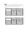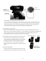
1
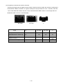
MODEL
WH 12DM
WR 12DM
POWER TOOLS
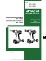
CORDLESS IMPACT DRIVER
WH 12DM
CORDLESS IMPACT WRENCH
WR 12DM
TECHNICAL DATA
AND
SERVICE MANUAL
WR12DM
WH12DM
W
EB1220BALh
EB1220BALh
2.0
2.0
WH 12DM
LIST Nos. WH 12DM: F862
WR 12DM: F864
WR 12DM
Oct. 2001
SPECIFICATIONS AND PARTS ARE SUBJECT TO CHANGE FOR IMPROVEMENT
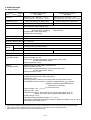
REMARK:
Throughout this TECHNICAL DATA AND SERVICE MANUAL, a symbol(s)
is(are) used in the place of company name(s) and model name(s) of our
competitor(s). The symbol(s) utilized here is(are) as follows:
WH 12DM
Competitor
Symbol Utilized
C
Company Name
Model Name
MAKITA
6916D
WR 12DM
Competitor
Symbol Utilized
C
Company Name
Model Name
MAKITA
6918D
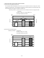
CONTENTS
Page
1. PRODUCT NAME ...........................................................................................................................1
2. MARKETING OBJECTIVE .............................................................................................................1
3. APPLICATIONS ..............................................................................................................................1
4. STANDARD EQUIPMENT ..............................................................................................................1
5. SELLING POINTS ..........................................................................................................................2
5-1. Selling Point Descriptions .............................................................................................................. 4
6. SPECIFICATIONS ........................................................................................................................14
6-1. Specifications ............................................................................................................................... 14
6-2. Optional Accessories ................................................................................................................... 15
7. COMPARISONS WITH SIMILAR PRODUCTS ............................................................................18
7-1. Specification Comparisons (Cordless Impact Driver) .................................................................. 18
7-2. Specification Comparisons (Cordless Impact Wrench) ............................................................... 19
7-3. Tightening Torque ........................................................................................................................ 20
7-4. Tightening Speed ......................................................................................................................... 23
7-5. Number of Screws or Bolts Driven ............................................................................................... 24
7.6 Actual Noise When Tightening Wood Screws and Bolts ............................................................... 25
8. PRECAUTIONS IN SALES PROMOTION ...................................................................................26
8-1. Safety Instructions ....................................................................................................................... 26
8-2. Tightening Torque Inspection Prior to Operation ......................................................................... 28
8-3. Tightening Torque Variation ......................................................................................................... 28
8-4. Suggestions and Precautions for the Efficient Use of the Charger .............................................. 29
9. OTHER PRECAUTIONS ..............................................................................................................30
10. REPAIR GUIDE ..........................................................................................................................31
10-1. Precautions in Disassembly and Reassembly ........................................................................... 31
10-2. Precautions in Disassembly and Reassembly of Battery Charger ............................................ 38
11. STANDARD REPAIR TIME (UNIT) SCHEDULES......................................................................39
Assembly Diagram for WH 12DM
Assembly Diagram for WR 12DM
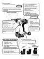
1. PRODUCT NAME
Hitachi Cordless Impact Driver, Model WH 12DM
Hitachi Cordless Impact Wrench, Model WR 12DM
2. MARKETING OBJECTIVE
Owing to the shift of demand from nails to screws and increased demand for long screws, there is a market need
for a powerful, high-speed, compact and easy-to-handle impact driver that provides more efficient operation per
charge. The new cordless impact driver Model WH 12DM ("Super Impact 12") is the upgraded version of the
previous Model WH 12DH, developed under the concept for more compact, powerful and convenient model to
plainly differentiate it from the competitors. Thanks to the new development/production technologies such as
computer analysis for optimum impacting operation and air ducts, 3-D CAD engineering and mold designing,
double-layer molding, blow molding and the new rare-earth magnet motor, the Model WH 12DM provides the
following features to respond to the user requests:
• 30% higher speed than the previous model
• High durability
• Comfortable handle grip
• Convenient functions including hook and bit holder
• New-type flat battery
The new cordless impact driver Model WH 12DM ("Super Impact 12") is the standard model of the Super Impact
series. This "Super Impact 12" is expected to expand our market share of the cordless impact products. The new
cordless impact wrench Model WR 12DM ("Super Wrench 12") is also brought out. The Model WR 12DM has the
maximum tightening torque of 150 N•m. It is substantially higher than the previous Model WR 12DH and
equivalent to the tightening torque of our higher-class 14.4-V cordless impact wrench.
3. APPLICATIONS
• Tightening/loosening of small screws, tapping screws, wood screws, bolts, nuts, etc.
• Drilling into wood and various other materials (with use of optional accessory drill chuck adapter).
[Applicable Markets]
• Wood-product assembly: Tightening/loosening of wood screws.
• Construction industry: Assembly of scaffolding, roofing, aluminum sashes, fencing, etc.; removal of plastic cones
from concrete forms, mounting/removal of form ties; drilling into the wood frames of concrete forms, etc.
• Manufacturing industry: Assembly work for automobiles, rolling stock, shipbuilding, agricultural machinery and
tools, industrial machines, steel furniture, etc.
• Utility industry: Assembly and installation of electric equipment, plumbing facilities, air conditioning (duct
assembly, etc.), sanitary fixtures and various other facilities.
• Service industry: General repair work; installation of advertising aids, automobile repair, assembly of garages
and carports storage sheds, etc.
• Various other assembly, construction or repair facilities.
4. STANDARD EQUIPMENT
The Models WH 12DM and WR 12DM come standard with the new-type flat battery.
(1) BL K specification: One EB 1220BL battery (NiCad, capacity 2.0 Ah), UC 14YF2 charger and case
(2) 2BLFK specification: Two EB 1220BL batteries (NiCad, capacity 2.0 Ah), UC 14YF2 charger and case
(3) HLFK specification: One EB 1230HL battery (NiMH, capacity 3.0 Ah), UC 14YF2 charger and case
(4) 2HLFK specification: Two EB 1230HL batteries (NiMH, capacity 3.0 Ah), UC 14YF2 charger and case
--- 1 ---
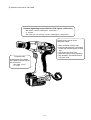
5. SELLING POINTS
High durability
(1) Cordless Impact Driver: WH 12DM
• High durability in continuous operation
(improved cooling efficiency):
Temperature rise is reduced to half of C
thanks to the 1.4 times thicker winding
(than C), powerful rare-earth magnet motor
(made in Hitachi Koki), large fan and
optimum air ducts.
• Improved dust resistance:
Ball bearings with contact seals
Labyrinth construction
• Long service life:
The gears and the motor section are
strengthened to realize powerful operation.
Powerful
Ultra-compact body but class-top tightening speed
(30% faster than the previous model, 10% faster than C)
Maximum torque 100 N•m, the same torque in forward/
reverse rotation
Enhanced maintainability
• Singly replaceable armature
• Replaceable carbon brushes
Convenient
Comfortable handle grip
Low operating noise
WH12DM
Powerful tightening thanks to
the large hammer
Noise level of the Model
WH 12DM compared with the
previous model
• When tightening wood
screws: -3 dB
• When tightening bolts: -4 dB
Shaped to comfortably fit
the operator's thumb
Slim grip
Soft and slip-resistant grip
(Two kinds of resins are firmly
adhered by fusion in the new
double-layer molding process,
M-DSI)
Rubber cap and soft material
To protect the main body
and the workpiece, and to
prevent slipping
Stepless variable speed switch
Startup speed is decreased to 20
rpm to prevent screws from falling
sideways.
EB1220BALh
2.0
New, compact and cyber design
Overall length of the Model WH 12DM
compared with the previous model
Overall length: -9 mm
Girth of housing: - 10 mm
Height: - 19 mm
Weight: - 80 g
Handle angle is changed from 5˚ to 10˚
(easy to handle).
Convenient one-touch hook
Quick slide-out hook (angle-adjustable)
Mountable on either side
Bit holder
Patent applied for
1.5 times
higher
capacity
NiCad
Conventional
batteries are usable
(B-type batteries).
Compact and stable flat battery
• Selectable from three types:
high-capacity NiMH battery, light-weight
NiMH battery and NiCad battery
• Conventional stand-up batteries (EB 12B, etc.)
are also usable.
Interchangeable
--- 2 ---
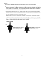
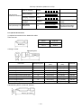
(2) Cordless Impact Driver: WR 12DM
Powerful tightening torque 150 N•m (1530 kgf•cm, 1330 in-lbs.)
WR 12DH: 118 N•m (1200 kgf•cm, 1040 in-lbs.)
C: 120 N•m
WR 14DH (14.4-V product): 147 N•m (1500 kgf•cm, 1302 in-lbs.)
Selling points common to the
Model WH 12DM
WR12DM
Compact body
Overall length of the Model
WR 12DM compared with the
previous model:
WR 12DH: -8 mm
C: -3 mm
EB12200BALh
2.
--- 3 ---
• Newly designed compact body
• Ergonomically designed comfortable
handle (slip-resistant double-molded
grip)
• Convenient one-touch hook
• Stable flat battery (interchangeable)
• High durability, dust resistance and
long service life
5-1. Selling Point Descriptions
Common selling points (Models WH 12DM and WR 12DM)
(1) New, compact and cyber design
The Models WH 12DM/WR 12DM have vibrant and cyber looks thanks to the widely adopted soft urethane
resin (elastomer) and the complicated 3-D curved surfaces, stirring up curiosity to touch them.
The Models WH 12DM/WR 12DM are equipped with a separate-type motor in which the armature is
separated from the magnet like a 100-V motor while the previous models are equipped with an integratedtype motor contained in a steel case. Thanks to the new separate-type motor, the steel case is eliminated
and the motor section is downsized. In addition, the hammer case is downsized. The overall length of the
Models WH 12DM/WR 12DM is shortened by 9 mm, the girth is shortened by 10 mm and the height is
shortened by 19 mm in comparison with the previous models as shown below. The Models WH 12DM/
WR 12DM are convenient for working in narrow places.
The weight of the Models WH 12DM/WR 12DM is heavier than C by about 80 g because they are equipped
with the hook, and the gears and the motor are strengthened to enhance the durability and the
performance.
The Models WH 12DM/WR 12DM are easy to handle and well balanced thanks to the change of the handle
angle from 5˚ to 10˚ to cope with the user demand (C: 15˚). This is the optimum angle determined in the
factory by making sample machines.
(2) High durability
Owing to the shift of demand from nails to screws and increased demand for long screws, impact drivers
having high heat resistance in continuous operation are much sought after. However, there are problems such
as heavy noise or vibration of the ball bearings and decrease in power if the impact drivers are used harshly in
dusty environments. In addition, higher strength and longer service life are required to continuously tighten
and loosen bolts in scaffolding and demolishing works. The Models WH 12DM/WR 12DM have high durability,
dust resistance and long service life in continuous operation as described below.
--- 4 ---
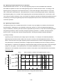
1 Enhanced heat resistance of the motor (Example: When tightening M12 bolts continuously (Cycle of
operation: 5-second impacting and 10-second stopping, 3.0 Ah battery used)
The heat resistance comparison between the Models WH 12DM/WR 12DM and C is shown below. The
Models WH 12DM/WR 12DM are equipped with a powerful motor having 9% larger core diameter, 13% larger
stacking length, 1.4 times thicker winding (2 times larger cross section of the conductor) and 33% larger
volume of the armature than C. The cooling efficiency is improved and the temperature rise is reduced to half
of C (when using two batteries) thanks to the powerful full-fledged large radial fan and the computer-analyzed
air ducts. Thus the Models WH 12DM/WR 12DM are protected from burnout due to long-time continuous use
and decrease in speed due to temperature rise. The motor is manufactured using the latest facilities in
Yamagata Plant.
Temperature
Burnout
250
C
200
C: Smoking
150
100
1 battery
2 batteries
HITACHI WH 12DM
3 batteries
50
0
As shown in the above graph, C produces smoke when operating on one battery. When tightening wood
screws (5.3 mm diameter and 120 mm long) into a workpiece (hemlock spruce) continuously, it suddenly takes
much time to tighten the tenth and the later screws. This is because thin wires used in the armature assembly
of C are apt to produce heat and the cooling construction is insufficient to reduce the heat.
Flow of cooling air around the armature
Large radial fan
Air inlet
Air outlet
--- 5 ---
2 Improved dust resistance
The dust-resistant contact seal bearings are provided at the commutator side and the fan side. Thanks to the
new bearings, hermeticity is enhanced because the seals of the bearings always contact the inner rings (C:
non-contact bearings). The labyrinth construction is provided between the housing and the fan at the pinion
side as shown in the figure below to ensure protection against dust because the pinion side must have high
durability against heavy loads. The air inlet is minimized and the powerful fan discharges dust if entered.
Labyrinth
Seal
The labyrinth
construction ensures
protection against dust.
Dust resistance is improved
thanks to the contact seal
bearings.
3 Improved service life and durability
Although the service life may vary depending on the frequency of use and the severity, the service life of the
Models WH 12DM/WR 12DM is 1.5 times longer than C in spite of the compact body because the Models
WH 12DM/WR 12DM have strong components such as the highly durable motor and the gears made of
specially heat-treated steel to realize powerful operation.
--- 6 ---
(3) Convenient one-touch hook
A hook is very convenient if there is no place to put the impact driver temporarily. Although various kinds of
hooks are on the market, there is a user demand for a standard accessory hook. To cope with this demand,
the Models WH 12DM/WR 12DM are equipped with the hook having the following features as a standard
accessory.
1 The hook can be quickly slid out and can be slid in when not needed.
2 The hook is mountable on either side to cope with the use by either right-handed persons and left-handed
persons. The mounting position can be changed by using a flat-blade screwdriver or a coin.
3 The angle of the hook is adjustable in five steps (0, 20, 40, 60 and 80˚). The hook can be adjusted to
the optimum position according to the weight of the bit in use.
4 The bit holder that can contain a 65-mm double-ended bit is provided. It is very convenient for holding a
spare bit.
Quick slide-out type
Angle-adjustable in five steps
(0, 20, 40, 60 and 80˚)
Mountable on either side
Bit holder
(4) Ergonomically designed comfortable handle
When the previous model is continuously operated, the housing tail rubs the base of the operator's thumb
and gives pain to the operator. To cope with this problem, the Models WH 12DM/WR 12DM are equipped
with the separate-type motor without case to make the housing tail section slim.
More delicate speed control is required at the start of tightening screws. The Models WH 12DM/WR 12DM
have a grip whose circumference at the switch section is shorter than C for ease of operation (grip
circumference at the switch section with respect to C: -14 mm).
The grip of the Models WH 12DM/WR 12DM is soft, slip-resistant and comfortable thanks to the soft resin
(elastomer) covered on the handle. The new double-layer molding process, M-DSI (Multi-layered Die Slide
Injection) is introduced to mold the nylon resin and the elastomer resin continuously in the same die. Since
the elastomer resin is molded while the formerly molded nylon resin is still hot, they are adhered by fusion
and the adhesion is so firm as to be torn if you try to remove the soft material layer from the nylon resin
layer.
--- 7 ---
WH 12DM
Short grip
circumference at
the switch section
Thumb
joint
Previous model
Soft and slipresistant grip
Slim tail section
* M-DSI (Abbreviation of "Multi-layered Die Slide Injection")
This is a molding process that allows the nylon resin and the elastomer resin to be molded continuously in
the same die in a short cycle by sliding the die. The nylon resin and the elastomer resin are adhered by
fusion because the nylon resin is covered with the elastomer resin while it is still hot, and thus the firm
laminate can be made (manufactured using the latest facilities in Yamagata Plant).
(5) New flat battery (interchangeable)
There are user requests for a new cordless impact driver that can stand upright stably and can also be
operated on the conventional batteries (chargers). The new flat batteries for the Models WH 12DM/WR 12DM
have low height and wide bottom enough to stand the Models WH 12DM/WR 12DM upright and are
interchangeable with the conventional stand-up batteries including EB 12B.
1.5 times higher capacity
NiCad
(6) Low operating noise (-3 dB with respect to the previous model)
Although the previous models give shrill noise, the operating
noise of the Models WH 12DM/WR 12DM is low and dull thanks
to the large hammer and the optimized impact timing without
increasing the revolution. Thus the large hammer tightens
screws powerfully with low operating noise. (Refer to page 25 for
details.)
Conventional
batteries are usable
(B-type batteries).
(7) Enhanced maintainability
The carbon brushes are replaceable and the armature is singly
replaceable thanks to the separate-type motor like a 100-V motor.
--- 8 ---
(8) Others
The Models WH 12DM/WR 12DM have the following features common to the previous models.
The thickness of the silver plating over the terminal is changed from 3 µ to 30 µ (10 times thicker) for longer
service life of the terminal. In addition, the terminal is movable according to the movement of the battery to
prevent damage to the contact portion. The contact between the housing and the battery is changed from
line contact to surface contact to minimize rattling due to wear.
To cope with the initial galling of the anvil, a hardened-steel metal with an oil groove for retaining grease
(C: powder-sintered, no groove) is provided at the tip and a dust-resistant seal is provided inside the metal
(the effect has already been proved by the Model WH 12DC2).
[Reference] Motor comparison of the Model WH 12DM with C is shown below. The Model WH 12DM is
equipped with a powerful motor having 1.4 times thicker winding, larger core diameter and stacking length
than C. In addition, the Model WH 12DM is equipped with the full-fledged fan having walls at both sides of
a blade for powerful cooling while C's fan is simple with only the blades.
HITACHI WH 12DM
C
114 g
87 g
Outside diameter of core: 30.5 mm
Stacking length of core: 17.0 mm
Diameter of winding: 0.85 mm
--- 9 ---
Outside diameter of core: 28.0 mm
Stacking length of core: 16.0 mm
Diameter of winding: 0.6 mm
Selling points of the Model WH 12DM
Class-top tightening speed
The Model WH 12DM is equipped with the new rare-earth magnet motor that is more powerful than the
previous model by 30% and the 35% larger hammer. With the computer analysis, the Model WH 12DM gives
optimum impact at tightening screws and the tightening speed is 30% higher than the previous model (10%
higher than C). The Model WH 12DM can also tighten long screws at high speed even into a hard wood
workpiece. Tightening time comparison of the Model WH 12DM with C is shown below. (Refer to pages 23
and later for detailed data on the tightening time and the working capacity.)
Tightening time comparison (Wood screw: 5.3 mm dia. x 120 mm length, hemlock spruce)
Fast
Model
1
2
3
Slow
4
5
6
7
8
9
10
sec.
6.5 sec.
HITACHI WH 12DM
9.5 sec.
HITACHI WH 12DH
7.2 sec.
C
* Tightening time may vary depending on hardness of the workpiece, ambient temperature, characteristics
of the battery, etc.
Maximum tightening torque: 100 N•m {1020 kgf•cm, 885 in-lbs.}
The Model WH 12DM is equipped with a powerful motor having 33% larger volume of the armature and 1.4
times thicker winding (2 times larger cross section of the conductor) than C to reduce temperature rise.
Because the tightening torque is the same in both forward and reverse rotations, the tightening torque is not
reduced even when loosening bolts (this is the same feature in the previous models). C's speed and
tightening torque in reverse direction are lower than those in forward direction because the position of the
motor brush is shifted to obtain high power with the small motor.
--- 10 ---
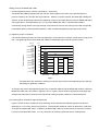
Selling points of the Model WR 12DM
Powerful tightening torque 150 N•m {1530 kgf•cm, 1330 in-lbs.}
The Model WR 12DM is equipped with the new rare-earth magnet motor that is more powerful than the
previous model by 30% and the 35% larger hammer. With the computer analysis, the Model WR 12DM gives
optimum impact at tightening bolts and the tightening torque is 27% higher than the previous Model WR 12DH,
25% higher than C, and equivalent to the 14.4 V-product Model WR 14DH. The Model WR 12DM is
mechanically strong thanks to the high-strength components such as the 30% stronger anvil and the specially
heat-treated gears to realize powerful operation. Data of measured tightening torque are shown below.
(1) Tightening torque comparison
It should be noted that a M16 F10T bolt was tightened in 3 seconds with a hexagon socket (40 mm long) in the
test. The tightening torque of the Model WR 12DM is substantially higher than the previous model.
Tightening torque
kgf • cm
2000
(1736 in-lbs)
1800
(1562 in-lbs)
1600
(1389 in-lbs)
1400
(1215 in-lbs)
1200
(1042 in-lbs)
1000
(868 in-lbs)
800
(694 in-lbs)
600
(521 in-lbs)
400
(347 in-lbs)
200
(174 in-lbs)
0
N• m
200
180
160
160
140
122
120
114
100
80
60
40
20
0
WR 12DM
WR 12DH
C
Fig. 1
* The data above are intended for reference purposes only because actual tightening torque will vary
depending on tightening conditions.
To describe the merit of high tightening torque, the comparison data among the Model WR 12DM, the previous
Model WR 12DH and C are shown in Figures 2 and 3. Figure 2 shows the time required for loosening a high
strength bolt and Figure 3 shows the time required for sinking a square washer into a wood workpiece.
(2) Loosening time comparison (high strength bolts)
Figure 2 shows the time comparison when loosening an M16 bolt that was statically tightened at 200 N•m
{2040 kgf•cm, 1770 in-lbs.} with a torque wrench. The Model WR 12DM can loosen an M16 bolt in a half time
of the previous Model WR 12DH. In addition, the Model WR 12DM can loosen bolts that cannot be loosened
by the previous Model WR 12DH. It is very convenient for loosening bolts that secure molding boxes.
--- 11 ---
9
8.1
8
7.4
Loosening time (sec.)
7
6
4.6
5
4
3
2
1
0
WR 12DM
WR 12DH
C
Fig. 2
*The data above are intended for reference purposes only because actual loosening torque will vary
depending on tightening conditions.
(3) Sinking time comparison (square washers)
Figure 3 shows the time required for tightening an M12 bolt into a pine laminated lumber of 105 mm square
until the square washers at both sides are sunk into the lumber by 1.3 mm respectively. The Model WR 12DM
can tighten strap bolts and corner bracings (used in Japanese wooden buildings) speedily as it can sink
washers into a workpiece quickly.
9
8.3
8.1
8
Tightening time (sec.)
7
6
5
4
3.2
3
2
1
0
WR 12DM
WR 12DH
C
Fig. 3
*The data above are intended for reference purposes only because actual time required for sinking
washers will vary depending on tightening conditions.
The 30% higher power motor and the 35% larger hammer are the main factors that increase the tightening
torque of the Model WR 12DM substantially. Comparison of hammer and number of strokes are shown below.
--- 12 ---
(4) Comparison of hammer and number of strokes
Thanks to the larger hammer (higher hammer inertia J) than the previous model, the number of strokes (N) of
the Model WR 12DM is increased. As a guide, stroking force is proportional for J X N2. Therefore, when the
J X N2 of the Model WR 12DH is 100, the J X N2 of the Model WR 12DM is about 1.5 times larger than the
Model WR 12DH as shown in the table below.
WR 12DM
WR 12DH
C
Unit
WH 12DM
WR 12DM
C
V
12
12
12
Outside diameter of hammer (D)
mm
42.6
39.5
42
Height of hammer (H)
mm
20
21
16.5
kgmm2
37.4
28.8
31.7
3140
2900
3070
150
100
120
Model
Voltage
Hammer inertia J
Number of strokes (N)
J x N2
min-1 (No. of strokes/min.)
%
--- 13 ---
6. SPECIFICATIONS
6-1. Specifications
Model
Cordless Impact Driver
WH 12DM
Item
Cordless Impact Wrench
WR 12DM
Small screw M4 --- M8 (5/32" --- 5/16")*1
Ordinary bolt M5 --- M12 (3/16" --- 15/32")
Capacity
Tightening torque
Ordinary bolt M6 --- M16 (1/4" --- 5/8")
High-strength bolt M6 --- M12 (1/4" --- 15/32")
100 N m (1020 kgf cm, 885 in-lbs.)*2
150 N m (1530 kgf cm, 1330 in-lbs.)*3
6.35 mm (1/4") Bit holder
12.7 mm (1/2") Square drive
•
Tip condition
•
•
Type of motor
Fan cooled rare-earth magnet motor
Enclosure
Main body: Polyamide resin + elastomer
Aluminum alloy die casting
Storage battery: ABS resin (black)
Charger: ABS resin (black)
•
Housing
Hammer case
• • • • • •
• • • • • •
Type of switch
Trigger switch with forward/reverse changeover pushing button (with brake)
Handle configuration
T-type
No-load rotational speed
0 --- 2,300 /min
Impact rate
0 --- 3,000 /min
Weight
Main body
1.6 kg (3.5 lbs.) (Includes battery)*4
Battery
0.68 kg (1.5 lbs.)
Overall length x height
167 mm (6-37/64") x 226 mm (8.9")
Center height
26 mm (1-1/64")
Battery
(Type EB 1220BL)
Sealed cylindrical nickel-cadmium batteries
Nominal voltage: DC 12V
Nominal life: Charging/discharging approximately 1,000 cycles
(in case of Model UC 14YF2)
Nominal capacity: 2.0 Ah
Battery
(Type EB 1230HL)
Sealed cylindrical nickel-metal hydride batteries
Nominal voltage: DC 12V
Nominal life: Charging/discharging approximately 500 cycles
(in case of Model UC 14YF2)
Nominal capacity: 3.0 Ah
Charger (UC 14YF2)
Charger power source: single-phase AC, 50/60 Hz
Voltage: Depending on the order specification
Power input: 44 W
Charging system: Constant current charge with full wave phase control
Overcharge protection system: (1) Battery voltage detection ( 2V system)
(2) Battery surface temperature detection
(thermostat or thermistor)
(3) 120-minute timer
Output voltage: 7.2 V --- 14.4 V
Output current: 1.9 A
Charging time: Approx. 60 minutes (for BL-type storage battery at 20 ˚C)
Approx. 90 minutes (for HL-type storage battery at 20 ˚C)
Product weight: 1.3 kg
Operable ambient temperature range: 0 ˚C --- 40 ˚C
The maximum allowable temperature of the EB 1220BL type battery is 60 ˚C and the
EB 1230HL type battery is 45 ˚C.
173 mm (6-13/16") x 226 mm (8.9")
*1: In the case of tapping screws and wood screws, a minimum of M3 (1/8") is possible.
*2: This torque is based on tightening an M12 (15/32") bolt (strength grade: 12.9) for 3 seconds with a hexagonal socket.
*3: This torque is based on tightening an M16 (5/8") bolt (F10T) for 3 seconds with a hexagonal socket.
*4: Main body does not include accessory tools (hexagonal bit, etc.).
--- 14 ---
Pilot lamp indications (Model UC 14YF2)
Red pilot lamp
remains lit or flashes.
0.5 sec ON, 0.5 sec OFF
Prior to charging
Blinks
During charging
Lit
Charging completed
Blinks
Charging not
possible
Flickers
High battery
Green pilot lamp is lit. temperature
Stays ON constantly
0.5 sec ON, 0.5 sec OFF
0.1 sec ON, 0.1 sec OFF
Stays ON constantly
Lit
Storage battery or charger
is faulty.
Charging not possible
because storage battery
temperature is too high.
6-2. Optional Accessories
(1) Optional accessories for the Model WH 12DM
• Plus driver bit
50 mm (2")
• Hexagon socket
Bit No.
Code No.
No. 2
992671
No. 3
992672
Stamped figures
L
B
Stamped figures
L
(mm)
B
(mm)
Code No.
5 mm Hexagon socket
8
65 (2-9/16")
8 (5/16")
996177
6 mm Hexagon socket
10
65 (2-9/16")
10 (3/8")
985329
5/16" Hexagon socket
12
65 (2-9/16")
12 (15/32")
996178
8 mm Hexagon socket
13
65 (2-9/16")
13 (1/2")
996179
10 mm Hexagon socket (small type)
14
65 (2-9/16")
14 (9/16")
996180
10 mm Hexagon socket
16
65 (2-9/16")
16 (5/8")
996181
10 mm Hexagon socket
17
65 (2-9/16")
17 (21/32")
996182
1/2" Hexagon long socket
21
166 (6-17/32")
21 (53/64")
996197
Part name
14 mm dia.
(35/64")
• Woodworking drill bit
(Code No. 959183)
83 mm (3-17/64")
--- 15 ---
• Drill chuck adaptor set
(Code No. 996195)
The drill chuck adaptor set permits mounting of various types of locally-available drill bits for a variety of drilling
operations.
(2) Optional accessories for the Model WR 12DM
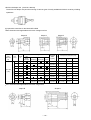
• Each dimension and applicable bolt for each hexagon socket
Shape B
Nominal diameter of applicable bolts
Part
name
Code
No.
ISO
(Highstrength)
10 mm 944291
ISO
(Ordinary)
Hexagon socket
12.7 mm
(1/2")
13 mm 873539
Dihedral
width
H (mm)
10 (3/8")
B
40 (1-9/16")
8 (5/16")
18 (23/32")
W 5/16" 12 (15/32") B
40 (1-9/16")
8 (5/16")
20 (25/32")
13 (1/2")
B
40 (1-9/16")
9 (11/32")
25 (1")
M 10 (3/8")
14 (9/16")
B
40 (1-9/16")
9 (11/32")
25 (1")
M 12 (15/32") W 3/8"
17 (21/32") C
32 (1-1/4")
8 (5/16")
28 (1-3/32")
34 (1-11/32")
9 (11/32")
28 (1-3/32")
ISO
(Small type)
Inch
screw
M 6 (1/4")
12 mm 873632
M 8 (5/16")
M 8 (5/16")
14 mm 873540
Shape D
Shape
Square
drive
dimension
Sq
Shape C
17 mm 873536
M 10 (3/8")
19 mm 873624
M 12 (15/32") M 14 (9/16") W 7/16" 19 (23/32") C
Socket primary dimensions (mm)
L
L1
D1
21(53/64")
D
36 (1-13/32") 10 (3/8")
32 (1-1/4")
22 mm 873627 M 12 (15/32") M 14 (9/16") M 16 (5/8")
22 (7/8")
D
40 (1-9/16")
14 (9/16")
35 (1-3/8")
24 mm 873629
24 (15/16") D
40 (1-9/16")
15 (9/16")
38 (1-1/2")
21 mm 873626
W 1/2"
M 16 (5/8")
M 18 (23/32")
• Each dimension and applicable bolt for each long socket
Shape D
Shape B
--- 16 ---
Nominal diameter of applicable bolts
Part
name
Code
No.
ISO
(Highstrength)
ISO
ISO
(Ordinary) (Small type)
M 8 (5/16")
12 mm 955138
13 mm 955139
Long socket
W 5/16" 12 (15/32")
L
L1
L2
D1
52 (2-3/64") 20 (25/32") 34(1-11/32") 20 (25/32")
13 (1/2")
B
52 (2-3/64") 20 (25/32") 34(1-11/32") 21.5 (53/64")
M 10 (3/8")
14 (9/16")
B
52 (2-3/64") 20 (25/32") 34(1-11/32") 22 (7/8")
17 mm 955141
M 10 (3/8")
M 12 (15/32") W 3/8"
17 (21/32")
B
52 (2-3/64") 24 (15/16") 34(1-11/32") 25 (1")
17 mm 955149
M 10 (3/8")
M 12 (15/32") W 3/8"
17 (21/32")
B
75 (2-15/16") 24 (15/16") 57(2-1/4")
19 mm 955142
M 12 (15/32") M 14 (9/6")
W 7/16" 19 (23/32")
B
52 (2-3/64") 24 (15/16") 34(1-11/32") 28 (1-3/32")
19 mm 955150
M 12 (15/32") M 14 (9/6")
W 7/16" 19 (23/32")
B
75 (2-15/16") 24 (15/16") 57(2-1/4")
25 (1")
28 (1-3/32")
21 mm 955143
W 1/2"
21 (53/64")
D
52 (2-3/64") 24 (15/16") 34(1-11/32") 31 (1-7/32")
21 mm 955151
W 1/2"
21 (53/64")
D
75 (2-15/16") 24 (15/16") 57(2-1/4")
21 mm 991480
W 1/2"
21 (53/64")
D
125 (4-47/51") 24 (15/16") 107 (4-7/32") 31 (1-7/32")
22 (7/8")
D
52 (2-3/64") 24 (15/16") 34(1-11/32") 32.5 (1-9/32")
24 (15/16")
D
52 (2-3/64") 25 (63/64") 34(1-11/32") 34 (1-11/32")
22 mm 955144 M 12 (15/32") M 14 (9/16") M 16 (5/8")
24 mm 955146
• Bit adaptor
Socket primary dimensions (mm)
B
M 8 (5/16")
14 mm 955140
12.7 mm
(1/2")
Inch
screw
Dihedral
width
H (mm)
Shape
Square
drive
dimension
Sq
M 16 (5/8")
M 18 (23/32")
31 (1-7/32")
(Code No. 991476)
6.35 mm (1/4")
12.7 mm (1/2")
45 mm (1-25/32")
13.5 mm dia.
(17/32")
Part name Overall length Code No.
(mm)
Plus hd.
45 (1-25/32")
955229
driver bit
No.2
70 (2-3/4")
955654
Plus hd.
45 (1-25/32")
955230
driver bit
70 (2-3/4")
955655
No.3
• Extension bar [Overall length 100 mm (3-15/16") ] (Code No. 873633)
• Universal joint (Code No. 992610)
• Socket ass'y for duct
• EW-14R corner attachment (Code No. 9329-9001)
--- 17 ---
Dihedral width of
applicable bolts
Code No.
12 (15/32")
993658
13 (1/2")
992613
14 (9/16")
992615
7. COMPARISONS WITH SIMILAR PRODUCTS
7-1. Specification Comparisons (Cordless Impact Driver)
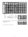
Maker
Model
WH 12DH
Small screw
M 4 --- M 8
1
(5/32" --- 5/16")*
M 4 --- M 8
(5/32" --- 5/16")*1
M 4 --- M 8
(5/32" --- 5/16")
Ordinary bolt
M 5 --- M 12
(3/16" --- 15/32")
M 5 --- M 12
(3/16" --- 15/32")
M 5 --- M 12
(3/16" --- 15/32")
M 5 --- M 10
(3/16" --- 3/8")
M 5 --- M 10
(3/16" --- 3/8")
M 5 --- M 10
(3/16" --- 3/8")
Catalog specifications
High-strength bolt
Max. tightening torque*2 N m
•
100
98
100
(1020 kgf cm, 885 in-lbs.) (1000 kgf cm, 868 ft-lbs.) (1020 kgf cm, 885 in-lbs.)
•
•
•
No-load rotation speed
/min
0 --- 2,300
0 --- 2,200
0 --- 2,300
Impact rate
/min
0 --- 3,000
0 --- 3,000
0 --- 3,000
kg
1.6 (3.5 lbs.)
1.7 (3.7 lbs.)
1.5 (3.3 lbs.)
3
Main body weight *
Max. tightening torque *
Measured figures
C
WH 12DM
Item
Capacity
HITACHI
2
Nm
•
105
109
112
(1140 kgf cm, 990 in-lbs.) (1070 kgf cm, 930 in-lbs.) (1110 kgf cm, 965 in-lbs.)
•
•
•
No-load rotation speed
/min
0 --- 2,390
0 --- 2,180
0 --- 2,750
Impact rate
/min
0 --- 2,800
0 --- 2,900
0 --- 2,660
Overall length x height
mm
167 x 226
(6-37/64" x 8.9")
Center height
mm
26 (1-1/64")
26 (1-1/64")
26 (1-1/64")
kg
1.66 (3.7 lbs.)
1.73 (3.8 lbs.)
1.58 (3.5 lbs.)
dB(A)
69
69
71
Driver chuck
Driver chuck
Driver chuck
Main body weight *3
No-load sound pressure level
Tool tip mounting system
176 x 245
(6-15/16" x 9-21/32")
168 x 231
(6-39/64" x 9-3/32")
Variable speed switch with Variable speed switch with Variable speed switch with
forward/reverse
forward/reverse
forward/reverse
changeover lever
changeover lever
changeover lever
Type of switch
Type of motor
DC magnet
DC magnet
DC magnet
Voltage
V
12
12
12
Current
A
28
17
26
EB 1220BL or EB 1230HL
EB 12B or EB 12H
1222
Ah
EB 1220BL: 2.0
EB 1230HL: 3.0
EB 12B: 2.0
EB 12H: 3.0
2.0
Nominal voltage
V
12
12
12
Ambient temperature
˚C
0 --- 40
0 --- 40
------
UC 14YF2
UC 14YF or UC 14YF2
DC1411
Type
Battery
Nominal capacity
Model
Charger Power input capacity
VA
44
44
------
Recharging voltage
V
7.2 --- 14.4
7.2 --- 14.4
7.2 --- 14.4
Standard accessories
• Plastic tool case
• Charger (UC 14YF2)
• Plastic tool case
• Plastic tool case
• Charger
• Charger
(UC 14YF or UC 14YF2)
*1: In the case of tapping screws and wood screws, a minimum of M3 (1/8") is possible.
*2: Max. tightening torque is based on tightening an M12 (5/32") bolt (strength grade: 12.9) for 3 seconds with a hexagon
socket.
*3: Main body weight does not include accessory tools (hexagon bit, etc.).
--- 18 ---
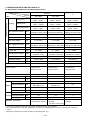
7-2. Specification Comparisons (Cordless Impact Wrench)
Maker
Model
Item
Catalog specifications
Ordinary bolt
Capacity
High-strength bolt
C
WR 12DM
WR 12DH
M 6 --- M 16
(1/4" --- 5/8")
M 6 --- M 14
(1/4" --- 9/16")
M 8 --- M 14
(5/16" --- 9/16")
M 6 --- M 12
(1/4" --- 15/32")
M 6 --- M 10
(1/4" --- 3/8")
M 6 --- M 12
(1/4" --- 15/32")
150*1
117.6*2
120*2
(1530 kgf cm, 1330 in-lbs.) (1200 kgf cm, 1040 in-lbs.) (1224 kgf cm, 1060 in-lbs.)
Max. tightening torque
Nm
No-load rotation speed
/min
0 --- 2,300
0 --- 2,200
0 --- 2,300
Impact rate
/min
0 --- 3,000
0 --- 3,000
0 --- 3,000
kg
1.6 (3.5 lbs.)
•
Main body weight
1
Max. tightening torque *
Measured figures
HITACHI
•
•
•
1.6 (3.5 lbs.)
1.7 (3.7 lbs.)
122
114
160
Nm
(1630 kgf cm, 1415 in-lbs.) (1245 kgf cm, 1080 in-lbs.) (1160 kgf cm, 1005 in-lbs.)
•
•
•
•
No-load rotation speed
/min
0 --- 2,390
0 --- 2,180
0 --- 2,750
Impact rate
/min
0 --- 2,800
0 --- 2,900
0 --- 3,070
Overall length x height
mm
173 x 226
(6-13/16" x 8.9")
Center height
mm
26 (1-1/64")
26 (1-1/64")
26 (1-1/64")
kg
1.67 (3.7 lbs.)
1.73 (3.8 lbs.)
1.60 (3.5 lbs.)
dB(A)
69
69
71
Main body weight *3
No-load sound pressure level
Tip condition
180 x 245
(7-1/8" x 9-21/32")
176 x 231
(6-15/16" x 9-3/32")
12.7 mm (1/2") Square drive 12.7 mm (1/2") Square drive 12.7 mm (1/2") Square drive
Tool tip mounting system
Plunger
Plunger
------
Variable speed switch with Variable speed switch with Variable speed switch with
forward/reverse
forward/reverse
forward/reverse
changeover lever
changeover lever
changeover lever
Type of switch
Type of motor
DC magnet
DC magnet
DC magnet
Voltage
V
12
12
12
Current
A
28
17
22
EB 1220BL or EB 1230HL
EB 12B or EB 12H
1222
Ah
EB 1220BL: 2.0
EB 1230HL: 3.0
EB 12B: 2.0
EB 12H: 3.0
2.0
Nominal voltage
V
12
12
12
Ambient temperature
˚C
5 --- 40
5 --- 40
------
UC 14YF2
UC 14YF or UC 14YF2
DC1411
Type
Battery
Nominal capacity
Model
Charger Power input capacity
VA
44
44
------
Recharging voltage
V
7.2 --- 14.4
7.2 --- 14.4
7.2 --- 14.4
Standard accessories
• Plastic tool case
• Charger (UC 14YF2)
• Plastic tool case
• Charger
• Plastic tool case
• Charger
(UC 14YF or UC 14YF2)
*1: Max. tightening torque is based on tightening an M16 (5/8") bolt (F10T) for 3 sec. with a hexagon socket.
*2: Max. tightening torque is based on tightening an M14 (9/16") bolt (strength grade: 12.9) for 3 sec. with a hexagon socket.
*3: Main body weight does not include accessory tools (hexagon bit, etc.).
--- 19 ---
7-3. Tightening Torque
7-3-1. Tightening torque characteristic comparisons
Thanks to the high-power rare-earth magnet motor and the larger hammer inertia, the Models WH 12DM/
WR 12DM can provide greater tightening torque.
(1) Impact driver
Test conditions
Bolt: M12 x 45 mm (15/32" x 1-25/32")
(strength grade: 12.9)
Steel plate: Mild steel
Thickness = 25 mm (1")
Accessory tool: Hexagon socket
WH 12DM
kgf • cm
N• m
120
Tightening torque
1200
(1042 in-lbs.)
1000
(868 in-lbs.)
100
800
(694 in-lbs.)
80
600
(521 in-lbs.)
60
400
(347 in-lbs.)
40
200
(174 in-lbs.)
20
C (forward)
WH 12DH
0
0
0
0
1
2
3
(sec.)
Tightening time
Fig. 4-1
(2) Impact wrench
WR 12DM
Tightening torque
kgf • cm
N• m
1600
(1389 in-lbs.)
160
1400
(1215 in-lbs.)
140
1200
(1042 in-lbs.)
120
1000
(868 in-lbs.)
100
800
(694 in-lbs.)
80
600
(521 in-lbs.)
60
400
(347 in-lbs.)
40
200
(174 in-lbs.)
20
0
Test conditions
Bolt: M16 x 55 mm (5/8" x 2-5/32") (F10T)
Steel plate: Mild steel
Thickness = 25 mm (1")
Accessory tool: Hexagon socket ass'y
WR 12DH
C
0
0
0
1
2
3
(sec.)
Tightening time
Fig. 4-2
--- 20 ---
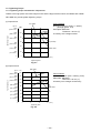
7-3-2. Screw diameter and appropriate tightening torque
Generally speaking, the appropriate tightening torque for a screw can be determined by the strength grade of the
screw and the material tightened. Tables 1 and 2, and Fig. 5 below list data relative to the strength grade of
various screws and the appropriate tightening torque. For further reference, appropriate tightening torque is
calculated with the following formula. Study and use this formula for accurate selection of tightening torque.
T=k d p
•
•
T: Appropriate tightening torque (kgf cm)
•
d: Nominal diameter for the screw (mm)
p: Recommended axial tightening force to be applied to the screw (kgf)
p=rated axial stress (kgf/cm2) x 0.8 x effective sectional area of the thread (mm2)
k: Torque coefficient (0.17)
• Strength grade and rated axial stress of threads
Table 1
Strength grade
4.8
6.8
8.8
12.9
Rated axial stress (kgf/mm2)
29.1
43.7
58.2
95
Material
Mild steel
Alloy steel including Ni, Mn, Cr, etc.
None
Processed-hard material
Heat treatment
• Diameter and effective sectional areas of threads
Table 2
Kind of thread (x pitch)
Effective sectional area
of thread (mm2)
M5 x 0.8 mm M6 x 1 mm
(3/16")
(1/4")
14.2
M8 x 1.25 mm M10 x 1.5 mm M12 x 1.75 mm M14 x 2 mm M16 x 2 mm
(15/32")
(9/16")
(5/16")
(3/18")
(5/8")
20.1
36.6
58.0
84.3
115
157
• Thread diameter and appropriate tightening torque
(kgf • cm)
1600
(1389 in-lbs)
1400
(1215 in-lbs)
1200
(1042 in-lbs)
1000
(868 in-lbs)
800
(694 in-lbs)
600
(521 in-lbs)
400
(347 in-lbs)
200
(174 in-lbs)
0
Strength grade 12.9
(high-strength bolt)
Nm
•
160
140
120
Strength grade 8.8
(high-strength bolt)
100
Strength grade 6.8
(ordinary bolt)
80
60
40
Strength grade 4.8
(ordinary bolt)
20
0
6
8
10
12
14
16
(1/4")
(5/16")
(3/8")
(15/32")
(9/16")
(5/8")
Fig. 5
--- 21 ---
mm
7-3-3. Bolt Tightening torque characteristics
Figures. 6-1 and 6-2 show relationships between time and tightening torque for individual bolt types and sizes.
While the data are useful for handy reference, actual tightening torque will vary depending on tightening
conditions and other variables. For details, please refer to Para. 8-3, "Tightening Torque Variation".
(Note)
• The term "tightening time" indicates the impact time after the lower surface of the bolt has come in contact with
the material into which it is being tightened.
• In the tightening conditions shown in Figs. 6-1 and 6-2, the screws are being tightened directly into a steel
plate; accordingly, the torque goes up very abruptly in comparison with ordinary bolt tightening conditions.
* The following bolts were utilized:
Ordinary bolt; strength grade 4.8
High-strength bolt; strengh grade
12.9
Steel plate
thickness: t
Bolt
Strength grade is read as follows:
4.8
Yield point or durable force:
(45,500 psi)
Tensile strength of the bolt:
(56,900 psi)
Nut
kgf • cm
(in-lbs.)
• Model WH 12DM
5/16" x 1-3/6"
(M8 x 30)
N• m
1000
(868)
100
800
(694)
80
600
(521)
60
400
(347)
40
200
(174)
20
0
0
3/8" x 1-3/6"
(M10 x 30)
kgf • cm
(in-lbs.)
N• m
1000
(868)
100
800
(694)
80
600
(521)
60
400
(347)
40
200
(174)
20
0
0
High-strength bolt
0
1
2
3
Tightening torque
High-strength bolt
Tightening torque
Tightening torque
kgf • cm
(in-lbs.)
Ordinary bolt
0
Tightening time: sec.
(Steel plate thickness
t=3/8" (10 mm))
2
1
3
15/32" x 1-3/4"
(M12 x 45)
N• m
1200
(1042)
120
1000
(868)
100
800
(694)
80
600
(521)
60
400
(347)
40
200
(174)
20
0
0
High-strength bolt
Ordinary bolt
2
1
0
3
Tightening time: sec.
(Steel plate thickness
t=3/8" (10 mm))
Tightening time: sec.
(Steel plate thickness
t=3/8" (10 mm))
Fig. 6-1
N• m
1000
(868)
100
800
(694)
80
600
(521)
60
3/8" x 1-5/32"
(M10 x 30)
High-strength bolt
1600
(1389)
160
1400
(1215)
140
1400
(1215)
1200
(1642)
120
1200
(1042)
1000
(868)
100
800
(694)
1000
(868)
800
(694)
120
High-strength bolt
100
80
60
40
400
(347)
40
200
(174)
20
0
0
60
400
(347)
Ordinary bolt
200
(174)
20
200
(174)
20
0
0
0
0
1
2
3
Tightening time: sec.
(Steel plate thickness
t=1" (25 mm))
Fig. 6-2
--- 22 ---
9/16" x 1-15/16"
(M14 x 50)
140
600
(521)
600
(521)
Ordinary bolt
High-strength bolt
80
40
2
3
1
0
Tightening time: sec.
(Steel plate thickness
t=3/8" (10 mm))
N• m
N• m
400
(347)
0
15/32" x 1-3/4"
(M12 x 45)
kgf • cm
(in-lbs.)
kgf • cm
(in-lbs.)
Tightening torque
kgf • cm
(in-lbs)
Tightening torque
Tightening torque
• Model WR 12DM
Ordinary bolt
0
1
2
3
Tightening time: sec.
(Steel plate thickness
t=1" (25 mm))
7-4. Tightening Time
Thanks to the new 30% higher power rare-earth magnet motor, the 35% larger hammer and the computer
analysis, the Model WH 12DM gives optimum impact at tightening screws and the tightening speed is 30% higher
than the previous model. Tightening time comparison is shown below.
The data below are intended for reference purposes only because actual tightening time will vary depending on
hardness of the workpiece, ambient temperature, characteristics of the battery, etc.
1 Wood screw 5.3 mm dia. x 120 mm length, hemlock spruce
Fast
Model
2
1
3
Slow
5
4
6
8
7
10
9
sec.
6.5 sec.
HITACHI WH 12DM
9.5 sec.
HITACHI WH 12DH
C
7.2 sec.
2 Wood screw 5.3 mm dia. x 120 mm length, lauan
Fast
Model
2
4
6
Slow
10
8
12
16
14
18
20
sec.
9.5 sec.
HITACHI WH 12DM
19 sec.
HITACHI WH 12DH
C
11.9 sec.
3 Wood screw 4.5 mm dia. x 90 mm length, hemlock spruce
Fast
Model
1
2
Slow
3
4
5
sec.
5
sec.
2.4 sec.
HITACHI WH 12DM
4.1 sec.
HITACHI WH 12DH
C
3.2 sec.
4 Wood screw 4.5 mm dia. x 90 mm length, lauan
Fast
Model
1
2
Slow
3
4
3.7 sec.
HITACHI WH 12DM
5.1 sec.
HITACHI WH 12DH
C
4.3 sec.
--- 23 ---
7-5. Number of Screws or Bolts Driven
7-5-1. Per-charge working capacity comparisons
Test data on the number of screws or bolts which can be driven per battery charge by the new models vs. the
previous models are shown in the tables below. Please note that the data below are intended for general
reference only as the number of screws which can be tightened per charge will vary slightly depending on screw
tightening conditions, screw sizes, ambient temperatures and the charging capacity of the battery.
(1) Number of screws or bolts driven (Cordless impact driver)
Model
Tightening condition
HITACHI
WH 12DM
HITACHI
WH 12DH
Battery
EB 1220BL
EB 12B
Wood screw 4.0 mm dia. x 50 mm
(soft wood)
575
545
635
Wood screw 4.2 mm dia. x 90 mm
(hard wood)
115
110
105
Wood screw 5.3 mm dia. x 120 mm
(hard wood)
45
40
40
Machine screw
(M8 x 16 mm)
1,280
1,215
C
1222
(Corresponding EB 1220BL)
1,475
Note 1) The Model WH 12DM is equipped with the larger hammer and the higher power motor for the higher
tightening speed. Although the higher tightening speed is realized, the Model WH 12DM has the
following disadvantage.
High startup current
The Model WH 12DM consumes higher power than C for driving a short or machine screw because it
requires high startup current. Thus the number of machine screws driven per charge is different as
shown above.
(2) Ordinary bolt (Cordless impact wrench)
Model
Tightening condition
HITACHI
WR 12DM
HITACHI
WR 12DH
Battery
EB 1220BL
EB 12B
M10 (3/8")
ordinary bolt
Number of bolts
Time (sec.)
755
0.4
755
M12 (15/32")
ordinary bolt
Number of bolts
Time (sec.)
475
0.6
475
0.8
M14 (9/16")
ordinary bolt
Number of bolts
Time (sec.)
335
0.9
335
1.2
0.5
--- 24 ---
7.6 Actual Noise When Tightening Wood Screws and Bolts
(1) Actual noise when tightening wood screws
The comparison data when tightening a wood screw (4.5 mm in diameter and 90 mm in length) into a cedar
workpiece are shown below. The data below are intended for reference purposes only because actual noise
will vary depending on the types of workpieces, hardness, etc.
Measuring conditions: (a) Wood screws (4.5 mm in diameter and 90 mm in length) and cedar
workpieces
(b) Battery voltage 12 V, A-range, distance 1 m
(c) Average of tightening 5 screws
(sec.)
3
(dB)
98
2.4
94
2.5
1.7
1.5
92
1.5
93.6
90
91.3
90.4
88
0
WH 12DM
WH 12DH
C
(2) Actual noise when tightening bolts
Measuring conditions:
(a) M12 bolts
(b) Battery voltage 12 V, A-range
(c) Average of tightening 5 screws
(dB)
98
96.2
96.1
WH 12DH
C
96
94
92
92.1
90
88
1
0.5
86
Actual noise
2
WH 12DM
--- 25 ---
Tightening time
Actual noise
96
8. PRECAUTIONS IN SALES PROMOTION
8-1. Safety Instructions
In the interest of promoting the safest and most efficient use of these tools by all our customers, it is very
important that at the time of sale the salesperson carefully ensures that the buyer seriously recognizes the
importance of the contents of the Handling Instructions, and fully understands the meaning of the precautions
listed on the Caution Plate and Name Plate attached to each tool.
A. Handling Instructions
Salespersons must be thoroughly familiar with the contents of the Handling Instructions in order to give pertinent
advice to the customer. In particular, they must have a thorough understanding of the precautions in the use of
the cordless (battery charger type) electric power tools which are different from those of ordinary electric power
tools.
(1) Before use, ensure that the unit is fully charged.
New units are not fully charged. Even if the units were fully charged at the factory, long periods without use,
such as during shipping, cause the storage battery to lose its charge. Customers must be instructed to fully
charge the unit prior to use.
(2) When charging storage batteries, use only the exclusive Model UC 14YF2 Charger provided with the tool.
Because of the designed rapid-charging feature (about one hour), use of other battery chargers is hazardous.
(3) Follow prescribed steps in using the charger.
First connect the EB 12 Storage Battery to the Model UC 14YF2 Charger, then plug the charger into an AC
outlet (ensuring that the voltage matches that indicated on the unit). If this order is reversed, the charger may
not function properly.
(4) Ensure the power source voltage is the same as that indicated on the Name Plate of the charger. Use of any
other power source (DC outlet, fuel powered generator, etc.) will cause the charger to overheat and burn out.
(5) Do not use any voltage increasing equipment (transformer, etc.) between the power source and the charger.
If the charger is used with voltage over and above that indicated on the unit, it will not function properly.
(6) Conduct battery charging at an ambient temperature range of 0 ˚C --- 40 ˚C (32 ˚F --- 104 ˚F).
Special temperature sensitive devices are employed in the charger to permit rapid charging. Ensure that
customers are instructed to use the charger at the indicated ambient temperature range. At temperatures
under 0 ˚C (32 ˚F), the thermostat will not function properly, and the storage battery may be over-charged.
At temperatures over 40 ˚C (104 ˚F), the storage battery cannot be sufficiently charged. The optimum
temperature range is 20 ˚C --- 25 ˚C (68 ˚F --- 77 ˚F).
(7) The battery charger should not be used continuously.
At high ambient temperatures, if over three storage batteries are charged in succession, the temperature of
the coils on the transformer will rise and there is a chance that the temperature fuse inserted in the interior of
the transformer will inadvertently melt. After charging one battery, please charge the next battery after about a
fifteen-minute interval.
(8) The charger case is equipped with air vents to protect the internal electronic components from overheating.
Caution the customer not to allow foreign materials, such as metallic or flammable objects, to be dropped or
inserted into the air vents. This could cause electric shock, fire or other serious hazards.
--- 26 ---
(9) Do not attempt to disassemble the storage battery or the charger.
Special devices, such as a thermostat, are built into the storage battery and charger to permit rapid charging.
Incorrect parts replacement and/or wiring will cause malfunctions which could result in fire or other hazards.
Instruct the customer to bring these units to an authorized service center in the event repair or replacement is
necessary.
(10) Disposal of the Type EB 1220BL or EB 1230HL Storage Battery
Ensure that all customers understand that Type EB 1220BL or EB 1230HL Storage Batteries should be turned
into any Hitachi power tool sales outlet or authorized service center when they are no longer capable of being
recharged or repaired. If thrown into a fire, the batteries may explode, or if discarded indiscriminately, leakage
of the cadmium compound contained in the battery may cause environmental pollution.
B. Caution Plates
(1) The following precautions are listed on the Name Plate or Caution Plate attached to the main body of each
tool.
For the U.S.A. (excludes French) or Canada
WARNING
• To reduce the risk of injury, user must read and
understand Instruction Manual.
AVERTISSEMENT
• Afin de réduire le risque de blessures, I'utilisateur doit lire
et bien comprendre le mode d'emploi.
For Oceania
CAUTION
• Read thoroughly HANDLING INSTRUCTIONS
before use.
(2) The following cautions are listed on the Name Plate attached to each type EB 1220BL or EB 1230HL storage
battery.
For Europe
CAUTION
before use.
• Read thoroughly HANDLING INSTRUCTIONS
• Do not disassemble nor throw into fire.
For the U.S.A.
CAUTION
• For safe operation, see Instruction Manual.
• Use HITACHI charger UC 12Y, -14Y, -24Y
series for recharging.
(3) The following caution is listed on the Name Plate attached to the Model UC 14YF2 Charger.
For the U.S.A.
CAUTION
• For safe operation, see Instruction Manual.
• Charge HITACHI rechargeable batteries Type EB 7, EB 9,
EB 12 and EB 14 series. Other types of batteries may
burst causing personal injury and damage.
• Charge between 32 and 104 ˚F.
• Indoor use only.
• Replace defective cord immediately.
--- 27 ---
8-2. Tightening Torque Inspection Prior to Operation
As described and shown in Para. 7-3-3, the output tightening torque of which the Models WH 12DM and
WR 12DM are capable in excess of the rated tightening torque of certain bolts and screws. Accordingly, if the
tightening time is prolonged for such bolts and screws, it could cause damage to their threads or, in the worst
case, cause them to be sheared off. (This phenomenon is common to all existing impact drivers.) Particularly
when tightening M6 (1/4") or smaller screws, tightening time must be kept extremely short: 0.5 seconds or less.
The customer should be advised to carry out several screw tightening operations and adjust the tightening time as
necessary by measuring the tightening torque with an appropriate torque wrench or driver before commencing
continuous operation.
8-3. Tightening Torque Variation
The tightening torque of the cordless impact driver or wrench may vary slightly in accordance with the factors
described below. Salespersons are requested to advise the customer to confirm that appropriate tightening
torque is obtained by measuring the torque with an appropriate torque wrench or torque driver at the beginning of
the tightening operations, and as necessary during the tightening operations. In addition, the torque values
shown in Para. 7-3-2 above are useful as a handy reference, and may be utilized as tentative standards.
(1) Voltage of battery
Tightening torque is affected by the voltage output of the battery. For example, the relationship between
tightening torque and the number of M16 x 55 mm (5/8" x 2-5/32") F10T bolts tightened is shown in Fig. 7
below. As can be seen in the graph, tightening torque decreases as the number of bolts tightened increases.
This phenomenon is caused by the decline in voltage output of the battery due to the increasing number of
bolts tightened. In particular, the tightening torque decreases rapidly just before the battery is fully discharged
(range "a" in the graph). As this phenomenon is an inherent drawback in any cordless impact driver,
salespersons are requested to ensure that the customer is fully aware of and understands this characteristic.
Model WR 12DM
(N m)
•
10
8
6
4
2
Tightening torque
Battery voltage
12
1,600
(1389 in-lbs.)
160
1,200
(1042 in-lbs.)
120
800
(694 in-lbs.)
80
400
(347 in-lbs.)
40
M16 x 55 (5/8" x 2-5/32") F10T (tightening time: 3 sec.)
a
When fully charged
When fully discharged
0
20
40
60
80
100
Number of bolts driven per charge (EB 1230HL battery)
Fig. 7
--- 28 ---
120
140
(pcs.)
(2) Effects of low ambient temperatures
The tightening torque required may be reduced at low ambient temperatures or under the influence of grease
and different torque coefficients (dependent on manufacturing and finishing processes, and specified by bolt
manufacturers).
(3) Different bolt diameter
Differences in bolt diameter will cause variation of the required levels of tightening torque. Generally speaking,
tightening torque is higher for large bolts.
(4) Different materials being tightened
When a bolt is tightened into a soft material such as aluminum, plastic, wood, etc., the tightening torque is
considerably less than when the bolt is tightened into a hard material such as steel.
(5) Different tightening conditions
The tightening torque may vary in accordance with bolt torque coefficient (dependent on manufacturing
process, and specified by bolt manufactures), bolt grade and bolt length, even though the dimensions of the
bolts are the same. Tightening torque may also vary depending on the surface finishing state of tightening
materials (steel, aluminum, etc.), and materials to be tightened. In addition, if there is seal packing, clearance,
etc., between tightening materials, the tightening torque is decreased.
(6) Wear and looseness of the socket
With extended use, the hexagonal portion of the socket which is fitted to the head of the bolt or drill bit, and/or
hexagonal portion of the driver chuck which is fitted onto the anvil in the main body will become worn and
loose. Wear and looseness will cause a proportionate loss of tightening torque.
In addition, use of an incorrect size socket (slightly larger than the bolt being tightened) will also result in
decreased torque.
(7) Bolt and nut rotate together
Tightening torque that can be achieved will be considerably decreased if the bolt and nut rotate together
during the tightening operation. The customer should be advised to carefully observe the operation and
ensure this does not occur.
8-4. Suggestions and Precautions for the Efficient Use of the Charger
(1) Batteries may not be rechargeable immediately after use
If the Models EB 1220BL and EB 1230HL Storage Batteries are exposed to direct sunshine for an extended
period, or if the temperature of the batteries is 40 ˚C (104 ˚F) or higher immediately after they have been used
in the tool, the pilot lamp may not light up when the batteries are connected to the Model UC 14YF2 Charger.
This is because the built-in thermostat functions to stop the charging when the temperature of the storage
batteries reach 40 ˚C (104 ˚F) or more. In such a case, the customer should be advised to place the batteries
in a shaded area with a good airflow, and allow sufficient cooling before recharging.
This phenomenon is common to all existing batteries which employ temperature sensitive overcharge devices.
The cooling time required before charging can be accomplished varies from a few minutes to about 30
minutes, depending on the load, duration of use, and ambient temperature.
--- 29 ---
9. OTHER PRECAUTIONS
(1) Check for cracks or other damage on the socket
Cracks or any other faults on the socket are very hazardous. In addition, cracks or other damage to
accessories will cause loss of tightening torque efficiency. Advise the customer to inspect accessories often,
and ensure there are no abnormalities.
(2) Socket dimensions
Without fail, utilize an appropriate socket which matches the bolt and/or nut dimensions. If the socket
dimensions are larger than the bolts or nuts, it will not only cause insufficient tightening torque, but could also
easily cause damage to the socket. Please refer to the tables in Para. 6-2 for appropriate socket dimensions.
(3) Hammering section lubrication
Grease (ATTOLUB MS No. 2) is utilized in the hammering section. Frequent or continuous use of the tool will
cause excessive temperature rise of the hammering section, resulting in depletion of the grease and
subsequent increased wear of components which will, in turn, cause loss of tightening efficiency. Accordingly,
it is necessary to periodically replenish the grease in the hammering section to ensure proper lubrication of
moving and sliding components.
(4) Vent holes in the handle
Do not stop up or cover the holes on either face of the handle. They are essential for ventilation.
--- 30 ---
10. REPAIR GUIDE
WARNING: Without fail, remove the Model EB 1220BL or EB 1230HL Battery from the main body before
starting repair or maintenance work. Because the tool is cordless, if the battery is left in and
the switch is activated inadvertently, the motor will start rotating unexpectedly, which could
cause serious injury.
10-1. Precautions in Disassembly and Reassembly
The [bold] and <bold> numbers correspond to the item numbers in the Parts List and the exploded assembly
diagram. ( [ ]: WH 12DM, < >: WR 12DM )
10-1-1. Disassembly
(1) Removal of Guide Sleeve (A) [4] (Model WH 12DM only)
Remove the Retaining Ring [1], Washer (D) [2], Guide Spring [3] and Guide Sleeve (A) [4] in order by
following the procedure shown in Figs. 8-1 to 8-4. Be sure not to lose the two Steel Balls D3.5 [8] in Anvil (C)
[9].
1
2
Anvil (C) [9]
Small flat-blade screwdriver
Retaining Ring [1]
Washer (D) [2]
Gap of retaining ring
Guide Sleeve (A) [4]
Fig. 8-1
Fig. 8-2
Hold the body and adjust the gap of the retaining
ring to the groove of anvil (C), then insert a small
flat-blade screwdriver into the groove at an angle.
Press down the Washer (D) with the small flat-blade
screwdriver.
4
3
Fig. 85-4
Fig. 8-3
Slide the small flat-blade screwdriver under one side
of the gap of the retaining ring.
Slowly raise the retaining ring using the end face of
guide sleeve (A) as a fulcrum.
Then slowly raise the other side of the retainer ring with the small flat-blade screwdriver until it is free. Avoid
quickly raising the retainer ring or it may fly out forcefully.
--- 31 ---
(2) Removal of the Hammer Case [7] <3> and the hammer assembly
Remove the four Tapping Screws (W/SP. Washer) D4 x 25 (Black) [6] <2> that connect the Hammer Case [7]
<3> with Housing (A). (B) Set [33] <30> and remove the Hammer Case [7] <3> and the hammer assembly
from Housing (A).(B) Set [33] <30>.
Mount the hammer assembly onto the
(3) Disassembly of the hammer assembly
J-297 base for washer (S). With a hand
press, push down the top of the Spindle
Spindle [17] <14>
[17] <14> to compress the Hammer Spring
Push down.
[14] <11>. In this position, remove the
Stopper [16] <13> with a flat-blade
Hammer Spring
[14] <11>
Washer (S) [15] <12>
screwdriver, then release the hand press.
(See Fig. 9.)
Stopper [16] <13>
J-297 base for washer (S)
Fig. 9
Remove the hammer assembly from the J-297 base for washer (S) and support the end surface of the Spindle
[17] <14>. With a hand press, push down either of the raised faces of Hammer [11] <8> to compress the
Hammer Spring [14] <11>. In this position, extract the two Steel Balls D5.556 [10] <7> from the cam grooves
of the Spindle [17] <14> and Hammer [11] <8> with a small flat-blade screwdriver or a similar tool. Then,
slowly release the hand press and lift Hammer [11] <8> and Washer (S) [15] <12> together to extract them
from the Spindle [17] <14>. The Hammer Spring [14] <11> can then be removed.
Raised faces of hammer
Spindle [17] <14>
Top of spindle cam
Steel Ball D5.556 [10] <7>
Hammer [11] <8>
Steel ball guide groove
Fig. 10
(4) Removal of the Carbon Brushes 5 x 6 x 11.5 [29] <26>
Remove the two Brush Caps [30] <27>. Catch the flanges of the Carbon Brushes 5 x 6 x 11.5 [29] <26> with
a small flat-blade screwdriver or a similar tool and remove the Carbon Brushes [29] <26> at both sides.
--- 32 ---
(5) Removal of the Hook Ass'y [39] <36>
Remove the Special Screw M5 [43] <40> with a flat-blade screwdriver or a coin and remove the Hook Ass'y
[39] <36> and the Hook Spring [42] <39>.
(6) Removal of Housing (B)
Remove the seven Tapping Screws (W/Flange) D4 x 20 (Black) [31] <28> from the main body. Before
removing Housing (B), be sure to remove the Brush Caps [30] <27> because Housing (B) cannot be removed
if the Brush Caps [30] <27> are mounted.
(7) Remove the FET of the DC-Speed Control Switch [36] <33> from the Dust Guard Fin [27] <24>. Then, the
Inner Cover [24] <21>, Armature ass'y [25] <22>, Magnet [26] <23>, Brush Block [28] <25> and DC-Speed
Control Switch [36] <33> can be removed in a piece. The Pushing Button [37] <34> and the Strap [41] <38>
can also be removed.
(8) Removal of the switch assembly
Remove the two Machine Screws (W/SP. Washer) M3 x 5 [35] <32> that secure the flag terminal and then
disconnect the internal wires (purple and black) of the Brush Block [28] <25> from the DC-Speed Control
Switch [36] <33>.
(Note) Do not disconnect the three FET internal wires soldered to the DC-Speed Control Switch.
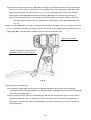
(9) Removal of the Magnet [26] <23> and the Dust Guard Fin [27] <24>
Remove the Magnet [26] <23> in the "B" direction (see Fig. 8) holding the Inner Cover [24] <21> securely
because the Magnet [26] <23> has a strong magnetism. The Dust Guard Fin [27] <24> can be easily
removed from the Magnet [26] <23> by pulling it in the "B" direction (see Fig. 11) because it is mounted to the
Magnet [26] <23> magnetically.
Inner Cover [24] <21>
Magnet [26] <23>
Inner Cover [24] <21>
Armature Ass'y
[25] <22>
Damper [23] <20>
Armature Ass'y
(Pinion) [25] <22>
Ring Gear
[20] <17>
Dust Guard Fin
[27] <24>
Adjust the convex of the dust guard
fin to the concave of the brush block.
Brush Block [28] <25>
Fig.11
--- 33 ---
Armature Ass'y
(Pinion) [25] <22>
(10) Removal of the Armature Ass'y [25] <22>
Support the Inner Cover [24] <21> so that it does not contact the
fan of the Armature Ass'y [25] <22>. With a hand press, push
[20] <17>
[21] <18>
[22] <19>
down the tip portion of Armature Ass'y (pinion) [25] <22> to
remove it.
[23] <20>
(11) Removal of the Ring Gear [20] <17> and the Damper [23] <20>
[24] <21>
Remove the Ring Gear [20] <17> from the Inner Cover [24] <21>
and remove the Damper [23] <20> with a small flat-blade
screwdriver.
Fig. 12
10-1-2. Reassembly
Reassembly can be accomplished by following the disassembly procedures in reverse. However, special
attention should be given to the following items.
(1) Reassembly of the housing assembly
(a) Be sure to follow the wiring diagram (Fig. 13) for proper wiring.
(b) When connecting the internal wires of the Brush Block [28] <25> to the DC-Speed Control Switch [36]
<33>, fasten them with the Machine Screw (W/SP. Washer) M3 x 5 [35] <32> paying attention to the
direction of the flag terminal (Fig. 13).
(Note) If the flag terminal is mounted in wrong direction, the flag
terminal may be damaged due to contact with the
housing. In addition, the gap between the housings (A)
Brush Block [28] <25>
and (B) is widened and dust may get into the housings
(A) and (B).
FET
Internal wire (black)
Flag terminal
Internal wire (purple)
Machine Screw (W/SP.
Washer) M3 x 5 [35] <32>
DC-Speed Control Switch [36] <33>
Fig. 13
--- 34 ---
(c) Mount a unit of the Inner Cover [24] <21> (including the Armature Ass'y [25] <22>), Magnet [26] <23>
(including the Dust Guard Fin [27] <24>) and Brush Block [28] <25> into housing (A) (See Fig. 15). Pay
attention to the following items.
Adjust the protrusion of the Dust Guard Fin [27] <24> to the notch of the Magnet [26] <23> when mounting
the Dust Guard Fin [27] <24> to the Magnet [26] <23> (See Fig. 14).
Insert the two Dampers [23] <18> so that they fit into the Inner Cover [24] <21>. Fit the locking rib of the
Ring Gear [20] <17> to the concave portion of the Damper [23] <20>. Press-fit the Armature Ass'y [25]
<22> into the Inner Cover [24] <21>.
Adjust the convex portion of the Dust Guard Fin [27] <22> to the concave portion of the Brush Block [28]
<25> (See Fig. 14).
Adjust the notch (for locking) of the Magnet [26] <23> to the protrusion of housing (A) (See Figs. 14 and
15).
Position the plate of the Dust Guard Fin [27] <24> under the rib of Housing (A) (See Fig. 16).
Brush Block [28] <25>
Concave
portion
Dust Guard Fin
[27] <24>
Convex
portion
Projection
Notch
Fig. 14
Align the projection of housing (A) to
the notch of the Magnet [26] <23>.
Housing (A)
Fig. 15
--- 35 ---
Magnet [26] <23>
(d) Mount the DC-Speed Control Switch [36] <33> to housing (A) so that the protrusion of the forward/reverse
lever at the top of the switch is inserted into the U-shaped groove of the Pushing Button [37] <34>. Apply
silicone grease (KS609, Shin-Etsu Chemical Co., Ltd.) to the contacting surfaces of the FET of the DCSpeed Control Switch [36] <33> and the Dust Guard Fin [27] <24> then mount them to housing (A).
(Note) The temperature of the FET may be high if the silicone grease is not applied. Make sure that the
three internal wires from the FET are passed above the DC-Speed Control Switch [36] <33> (see
Fig. 16).
(2) Mount the Strap [41] <38> to housing (A) and apply silicone rubber (ThreeBond 1211) to housing (A) as shown
in Fig. 16. Mount housing (B) to housing (A) and secure them with seven Tapping Screws (W/Flange) D4 x 20
(Black) [31] <28>. Wipe the silicone rubber coming out of the housing with a cloth.
Apply silicone rubber.
Position the plate of the Dust Guard Fin
[27] <24> under the rib of housing (A).
Fig. 16
(3) Mounting the mechanical parts
(a) Put Washer (S) [15] <12> onto the shaft of the Spindle [17] <14> and mount the Hammer [11] <8>
containing the twenty-eight Steel Balls D3.175 [12] <9>, Washer (J) [13] <10> and the Hammer Spring [14]
<11> to the Spindle [17] <14>.
(b) Align the top of the cam groove on the Spindle [17] <14> with the steel ball guide groove on the Hammer
[11] <8> as illustrated in Fig. 10. Press down either of the raised faces of the Hammer [11] <8> with a
hand press to compress the Hammer Spring [14] <11> until the end surface of the hammer contacts the
Spindle [17] <14>.
--- 36 ---
(c) Insert the two Steel Balls D5.556 [10] <7> into the steel ball guide groove. Check that the steel balls are
properly inserted in the cam groove. Then release the hand press.
(d) Mount the hammer assembly onto the J297 base for washer (S). With a hand press, push down the top of
the Spindle [17] <14> to compress the Hammer Spring [14] <11>. On this condition, mount the Stopper
[16] <13> onto the spindle shaft and then release the hand press.
(4) Mounting the hammer assembly to the housing
Raise the housing assembled in step (2) and mount the hammer assembly to the housing being careful of
proper engagement between the Idle Gear Set [18] <15> of the hammer assembly (check that Washer (E)
[21] <18> is mounted on the Spindle [17] <14>) and the Ring Gear [20] <17>. After mounting, check that the
hammer assembly turns. If the hammer assembly does not turn, the gears engage improperly.
(5) Mounting the hammer case
Put Anvil (C) [9] or Anvil (L) Ass'y <6> on the Spindle [17] <14>. Cover it with the Hammer Case [7] <3> and
secure with the four Tapping Screws (W/SP. Washer) D4 x 25 (Black) [6] <2>.
(6) Mounting Guide Sleeve (A) [4] (WH 12DM only)
Insert the two Steel Balls D3.5 [8] into the hole of
Anvil (C) [9]. Mount the Guide Sleeve (A) [4],
Guide Spring [3] and Washer (D) [2] in sequence.
Push down.
Mount the Retaining Ring [1] into the groove of
anvil using the J295 jigs (A) and (B) for retaining
ring as illustrated in Fig. 17.
Retaining Ring [1]
J295 jig (B) for retaining ring
Washer (D) [2]
J295 jig (A) for retaining ring
Fig. 17
(7) Reassembly of the hook
Check that the V-Lock Nut M5 [40] <37> is mounted into the Hook Ass'y [39] <36>. Mount the Hook Spring
[42] <39> and secure it with the Special Screw M5 [43] <40>. (Make sure to mount the Hook Spring [42]
<39> with its larger diameter side pointing inward the housing.)
(8) Checking the direction of rotation
Check whether the direction of rotation of Anvil (C) [9] or Anvil (L) Ass'y <6> coincides with the directional
markings on the push-on side of the Pushing Button [37] <34>. When the Pushing Button [37] <34> is turned
to (R) side, the direction of rotation of Anvil (C) [9] or Anvil (L) Ass'y <6> should be clockwise, as viewed from
behind.
--- 37 ---
(9) Lubrication
(a) ATTOLUB MS No. 2
• Cam groove and sliding section of the Spindle [17] <14>
• Cam groove and oil groove of the Hammer [11] <8>
• 8 mm diameter hole of Anvil (C) [9] or Anvil (L) Ass'y <6>, sliding section between Anvil (C) [9] or Anvil
(L) Ass'y <6> and the metal, and upper surface of the claw
• Two Steel Balls D5.556 [10] <7>
• Pinion tooth flanks of the Armature Ass'y [25] <22>, tooth flanks of the Ring Gear [20] <17>, tooth flanks
of the Idle Gear Set (2 pcs.) [18] <15>
• Metal oil groove of the Hammer Case [7] <3>
• Twenty-eight Steel Balls D3.175 [12] <9>
(b) HITACHI MOTOR GREASE No. 29 (WH 12DM only)
• Two Steel Balls D3.5 [8]
• Sliding section between Anvil (C) [9] and Guide Sleeve (A) [4]
(c) MOLUB-ALLOY 777-1
• All around the Needle Roller [19] <16>
• 5 mm diameter hole of Idle Gear Set (2 pcs.) [18] <15>
(10) Screw tightening torque
• Tapping Screw (W/SP. Washer) D4 x 25 (Black) [6] <2>
• Tapping Screw (W/Flange) D4 x 20 (Black) [31] <28>
• Machine Screw (W/SP. Washer) M3 x 5 [35] <32>
• Special Screw M5 [43] <40>
• Brush cap [30] <27>
• • •
1.96
0.49 N m (20
•
5 kgf cm, 17.4
4.3 in-lbs.)
• • • • ••
1.96
0.49 N m (20
5 kgf cm, 17.4
4.3 in-lbs.)
• • • • • • • • • • • •
•
•
•
0.29 --- 0.39 N m (3 --- 4 kgf cm, 2.6 --- 3.5 in-lbs.)
•
• • • • • • • • • • • • • • • • • • • • • • • • • • • • • • • • • • • • • • • • • • •
1.96
0.49 N m (20
• • • • • • • • • • • • • • • • • • • • • • • • • • • • • • • • • • • • • • • • • • • • • • • • • • • • • •
0.78
0.10 N m (8
•
•
•
5 kgf cm, 17.4
•
1 kgf cm, 6.9
•
4.3 in-lbs.)
0.9 in-lbs.)
10-2. Precautions in Disassembly and Reassembly of Battery Charger
Refer to the Technical Data and Service Manual for precautions in disassembly and reassembly of the Model
UC 14YF2 Battery Charger.
--- 38 ---
11. STANDARD REPAIR TIME (UNIT) SCHEDULES
MODEL
Variable
Fixed
10
20
30
Work Flow
WH 12DM
WR 12DM
DC-Speed
Control Switch
Housing
(A).(B) Set
Inner Cover
Armature Ass'y
Magnet
Brush Block
General Assembly
Hammer Case
Washer
Anvil (B)
Ring Gear
--- 39 ---
Steel Ball
Hammer
Washer
Hammer Spring
Spindle
Idle Gear Set
Needle Roller
Ball Bearing
(6901VV)
40
50
60 min.
LIST NO. F862
ELECTRIC TOOL PARTS LIST
CORDLESS IMPACT DRIVER
Model WH 12DM
2001 • 10 • 5
(E1)
1
501
2
502
3
4
5
6
7
8
9
20
10
11
21
12
22
13
23
14
24
15
25
16
17
18
26
19
27
28
29
30
31
32
36
45
33
34
37
35
35
43
42
38
44
39
40
41
PARTS
ITEM
NO.
1
*
WH12DM
CODE NO.
315-984
NO.
USED
DESCRIPTION
RETAINING RING
1
2
315-983
WASHER (D)
1
3
315-982
GUIDE SPRING
1
4
319-921
GUIDE SLEEVE (A)
1
5
320-418
FRONT CAP
1
6
319-917
TAPPING SCREW (W/SP. WASHER) D4X25 (BLACK)
4
7
319-923
HAMMER CASE
1
8
319-535
STEEL BALL D3.5 (10 PCS.)
2
9
320-417
ANVIL (C)
1
10
959-154
STEEL BALL D5.556 (10 PCS.)
2
11
319-916
HAMMER
12
959-148
STEEL BALL D3.175 (10 PCS.)
13
315-978
WASHER (J)
1
14
319-915
HAMMER SPRING
1
15
316-172
WASHER (S)
1
16
316-171
STOPPER
1
17
319-912
SPINDLE
1
18
319-913
IDLE GEAR SET (2 PCS.)
2
19
319-914
NEEDLE ROLLER
2
20
319-910
RING GEAR
1
21
319-911
WASHER (E)
1
22
690-1VV
BALL BEARING 6901VVCMPS2L
1
23
319-909
DAMPER
2
24
319-908
INNER COVER
1
25
360-557
ARMATURE ASS’Y (W/BALL BEARING) DC 12V
1
26
319-919
MAGNET
1
27
319-907
DUST GUARD FIN
1
28
319-905
BRUSH BLOCK
1
29
999-054
CARBON BRUSH 5X6X11.5 (1 PAIR)
2
30
319-918
BRUSH CAP
2
31
302-086
32
1
28
TAPPING SCREW (W/FLANGE) D4X20 (BLACK)
7
NAME PLATE
1
33
320-381
HOUSING (A).(B) SET
1
34
316-186
SUPPORT (B)
1
35
994-532
MACHINE SCREW (W/SP. WASHER) M3X5
2
36
319-906
DC-SPEED CONTROL SWITCH
1
37
316-166
PUSHING BUTTON
1
HITACHI LABEL
1
320-287
HOOK ASS’Y
1
38
39
40
320-288
V-LOCK NUT M5
1
41
306-952
STRAP (BLACK)
1
42
319-926
HOOK SPRING
1
43
319-927
SPECIAL SCREW M5
1
*
44
320-387
BATTERY EB 1220BL (W/ENGLISH N.P.)
1
*
44
320-386
BATTERY EB 1220BL (W/ENGLISH N.P.)
1
*
44
320-388
BATTERY EB 1230HL (W/ENGLISH N.P.)
1
*
45
CAUTION PLATE
1
--- 2 ---
REMARKS
INCLUD.40
FOR USA,CAN
FOR USA
* ALTERNATIVE PARTS
10 -- 01
WH12DM
STANDARD ACCESSORIES
ITEM
NO.
501
502
CODE NO.
320-377
NO.
USED
DESCRIPTION
CHARGER (MODEL UC 14YF2)
1
CASE
1
REMARKS
OPTIONAL ACCESSORIES
ITEM
NO.
* 601
* 601
CODE NO.
NO.
USED
DESCRIPTION
310-378
BATTERY EB 12B (W/ENGLISH N.P.)
1
310-453
BATTERY EB 12B (W/ENGLISH N.P.)
1 FOR USA,CAN
* 601
316-665
BATTERY EB 12H (W/ENGLISH N.P.)
1
602
992-671
+ DRIVER BIT (B) NO.2 50L
1
603
992-672
+ DRIVER BIT (B) NO.3 50L
1
604
996-177
NON-MAGNETIC HEX. SOCKET 8MM 65L
1
605
985-329
NON-MAGNETIC HEX. SOCKET 10MM 65L
1
606
996-178
NON-MAGNETIC HEX. SOCKET 12MM 65L
1
607
996-179
NON-MAGNETIC HEX. SOCKET 13MM 65L
1
608
996-180
NON-MAGNETIC HEX. SOCKET 14MM 65L
1
609
996-181
NON-MAGNETIC HEX. SOCKET 16MM 65L
1
REMARKS
610
996-182
NON-MAGNETIC HEX. SOCKET 17MM 65L
1
611
996-197
HEX. SOCKET (LONG) 21MMX166L
1
612
996-195
DRILL CHUCK AND ADAPTER SET
1 INCLUD.613,614
613
930-119
CHUCK WRENCH 6.5G
1
614
307-543
CHUCK ADAPTER
1
615
309-922
GREASE FOR IMPACT DRIVER (500G)
1
10 -- 01
* ALTERNATIVE PARTS
--- 3 ---
WH12DM
ITEM
NO.
--- 4 ---
CODE NO.
DESCRIPTION
NO.
USED
REMARKS
Printed in Japan 10 -- 01
(011005N)
LIST NO.
F864
ELECTRIC TOOL PARTS LIST
CORDLESS IMPACT WRENCH
Model WR 12DM
2001 • 10 • 25
(E1)
501
1
502
2
3
4
5
6
7
8
9
17
10
11
18
12
19
13
20
14
21
15
16
22
23
24
25
26
27
28
29
32
34
30
32
33
31
40
39
35
41
36
37
38
PARTS
ITEM
NO.
1
WR 12DM
CODE NO.
DESCRIPTION
NO.
USED
320-383
FRONT CAP
1
2
319-917
TAPPING SCREW (W/SP. WASHER) D4X25 (BLACK)
4
3
320-382
HAMMER CASE
1
4
985-209
PIN RETAINER
1
5
985-208
PLUNGER
1
6
320-384
ANVIL (L) ASS’Y
1 INCLUD.4,5
7
959-154
STEEL BALL D5.556 (10 PCS.)
2
8
319-916
HAMMER
1
9
959-148
STEEL BALL D3.175 (10 PCS.)
28
10
315-978
WASHER (J)
1
11
319-915
HAMMER SPRING
1
12
316-172
WASHER (S)
1
13
316-171
STOPPER
1
14
319-912
SPINDLE
1
15
319-913
IDLE GEAR SET (2 PCS.)
2
16
319-914
NEEDLE ROLLER
2
17
319-910
RING GEAR
1
18
319-911
WASHER (E)
1
19
690-1VV
BALL BEARING 6901VVCMPS2L
1
20
319-909
DAMPER
2
21
319-908
INNER COVER
1
22
360-557
ARMATURE ASS’Y (W/BALL BEARING) DC 12V
1
23
319-919
MAGNET
1
24
319-907
DUST GUARD FIN
1
25
320-376
BRUSH BLOCK
1
26
999-054
CARBON BRUSH 5X6X11.5 (1 PAIR)
2
27
319-918
BRUSH CAP
2
28
302-086
TAPPING SCREW (W/FLANGE) D4X20 (BLACK)
7
NAME PLATE
1
HOUSING (A).(B) SET
1
CAUTION PLATE
1 FOR USA
*
29
*
31
30
320-381
32
994-532
MACHINE SCREW (W/SP. WASHER) M3X5
2
33
319-906
DC-SPEED CONTROL SWITCH
1
34
316-166
PUSHING BUTTON
1
HITACHI LABEL
1
35
36
320-378
HOOK ASS’Y
1 INCLUD.37
37
320-288
V-LOCK NUT M5
1
38
306-952
STRAP (BLACK)
1
39
319-926
HOOK SPRING
1
40
319-927
SPECIAL SCREW M5
1
*
41
320-387
BATTERY EB 1220BL (W/ENGLISH N.P.)
2
*
41
320-386
BATTERY EB 1220BL (W/ENGLISH N.P.)
1 FOR USA,CAN
*
41
320-388
BATTERY EB 1230HL (W/ENGLISH N.P.)
1
--- 2 ---
REMARKS
* ALTERNATIVE PARTS
10 -- 01
WR 12DM
STANDARD ACCESSORIES
ITEM
NO.
501
502
CODE NO.
320-377
NO.
USED
DESCRIPTION
CHARGER (MODEL UC 14YF2)
1
CASE
1
REMARKS
OPTIONAL ACCESSORIES
ITEM
NO.
* 601
CODE NO.
NO.
USED
DESCRIPTION
310-378
BATTERY EB 12B (W/ENGLISH N.P.)
REMARKS
1
*
601
310-452
BATTERY EB 12B (W/ENGLISH N.P.)
1 FOR NZL,AUS
*
601
310-453
BATTERY EB 12B (W/ENGLISH N.P.)
1 FOR USA,CAN
CORNER ATTACHMENT ASS’Y
1 INCLUD.603-619
955-300
HOUSING
1
602
603
604
955-301
METAL
3
605
955-302
SPINDLE
1
HITACHI LABEL
1
606
607
955-303
BEARING RACE
2
608
955-304
NEEDLE THRUST BEARING (NTA-1413)
2
609
955-305
COVER
1
610
955-306
NEEDLE BEARING (NTN BK1012)
1
611
948-227
RETAINING RING FOR D47 HOLE
1
612
955-307
PINION
1
613
955-308
SLEEVE
1
614
955-309
WASHER
1
615
955-310
SOCKET COVER
1
616
955-311
SOCKET
1
617
303-247
SEAL LOCK HEX. SOCKET HD. BOLT M5X25
6
618
873-537
SOCKET PIN
1
619
873-187
O-RING (J1SW1516)
1
620
991-481
FORM TIE SOCKET ASS’Y 11.3MMX95L
1 INCLUD.618,619
621
992-610
UNIVERSAL JOINT ASS’Y
1 INCLUD.618,619
622
955-153
UNIVERSAL JOINT PIN
1
623
991-476
BIT ADAPTER ASS’Y
1 INCLUD.618,619
624
944-291
HEX. SOCKET ASS’Y 10MMX40L
1 INCLUD.618,619
625
873-632
HEX. SOCKET ASS’Y 12MMX40L
1 INCLUD.618,619
626
873-539
HEX. SOCKET ASS’Y 13MMX40L
1 INCLUD.618,619
627
873-540
HEX. SOCKET ASS’Y 14MMX40L
1 INCLUD.618,619
628
873-536
HEX. SOCKET ASS’Y 17MMX32L
1 INCLUD.618,619
629
873-624
HEX. SOCKET ASS’Y 19MMX34L
1 INCLUD.618,619
10 -- 01
* ALTERNATIVE PARTS
--- 3 ---
WR 12DM
OPTIONAL ACCESSORIES
ITEM
NO.
630
631
CODE NO.
NO.
USED
DESCRIPTION
REMARKS
873-626
HEX. SOCKET ASS’Y 21MMX36L
1
INCLUD.618,619
873-627
HEX. SOCKET ASS’Y 22MMX40L
1
INCLUD.618,619
632
955-138
HEX. SOCKET ASS’Y (LONG) 12MMX52L
1
INCLUD.618,619
633
955-139
HEX. SOCKET ASS’Y (LONG) 13MMX52L
1
INCLUD.618,619
634
955-140
HEX. SOCKET ASS’Y (LONG) 14MMX52L
1
INCLUD.618,619
635
955-141
HEX. SOCKET ASS’Y (LONG) 17MMX52L
1
INCLUD.618,619
636
955-149
HEX. SOCKET ASS’Y (LONG) 17MMX75L
1
INCLUD.618,619
637
955-142
HEX. SOCKET ASS’Y (LONG) 19MMX52L
1
INCLUD.618,619
638
955-150
HEX. SOCKET ASS’Y (LONG) 19MMX75L
1
INCLUD.618,619
639
955-143
HEX. SOCKET ASS’Y (LONG) 21MMX52L
1
INCLUD.618,619
640
955-151
HEX. SOCKET ASS’Y (LONG) 21MMX75L
1
INCLUD.618,619
641
991-480
HEX. SOCKET ASS’Y (LONG) 21MMX125L
1
INCLUD.618,619
642
955-144
HEX. SOCKET ASS’Y (LONG) 22MMX52L
1
INCLUD.618,619
643
986-058
HEX. SOCKET FOR PLASTIC CONE 12MMX70L
1
INCLUD.618,619
644
873-633
EXTENSION BAR ASS’Y (SQUARE) 12.7MMX100L
1
INCLUD.618,619
INCLUD.618,619,646
645
993-658
SOCKET ASS’Y FOR DUCT 12MMX95L
1
646
993-659
SOCKET FOR DUCT 12MMX52L
1
647
992-613
SOCKET ASS’Y FOR DUCT 13MMX95L
1
648
992-614
SOCKET FOR DUCT 13MMX52L
1
649
992-615
SOCKET ASS’Y FOR DUCT 14MMX95L
1
650
992-616
SOCKET FOR DUCT 14MMX52L
1
651
309-922
GREASE FOR IMPACT DRIVER (500G)
1
--- 4 ---
INCLUD.618,619,648
INCLUD.618,619,650
* ALTERNATIVE PARTS
Printed in Japan
(011025N)
10 -- 01