1
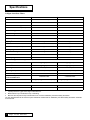
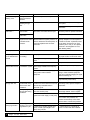
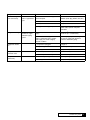
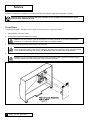
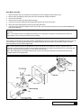
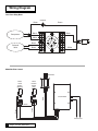
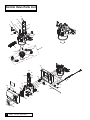
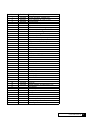
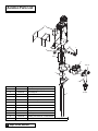
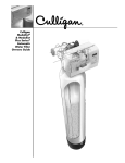
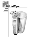
Cat. No. 01018680
Rev. A 10/30/07
DCO # 010258
Installation
and Operation
Instructions
with Parts List
Culligan® Iron-Cleer®
Water Filters
Models from 2006
© 2007 Culligan International Company
Attention Culligan Customer:
The installation, service and maintenance of this equipment should be rendered by a
qualified and trained service technician. Your local independently operated Culligan
dealer employs trained service and maintenance personnel who are experienced in
the installation, function and repair of Culligan equipment. This publication is written
specifically for these individuals and is intended for their use.
We encourage Culligan users to learn about Culligan products, but we believe that
product knowledge is best obtained by consulting with your Culligan dealer. Untrained
individuals who use this manual assume the risk of any resulting property damage or
personal injury.
Warning! Prior to servicing equipment, disconnect power supply to prevent
electrical shock.
Warning! If incorrectly installed, operated or maintained, this product can
cause severe injury. Those who install, operate, or maintain this product
should be trained in its proper use, warned of its dangers, and should read the
entire manual before attempting to install, operate, or maintain this product.
Culligan International, Inc.
9399 West Higgins Road, Suite 1100
Rosemont, IL 60018
(847) 285-5442
Installation
and Operation
Instructions
with Parts List
Culligan® Iron-Cleer®
Water Filters
Models from 2006
Table of Contents
Page
Introduction . . . . . . . . . . . . . . . . . . . . . . . . . . . . . . . . . . . .1
Specifications . . . . . . . . . . . . . . . . . . . . . . . . . . . . . . . . . . .2
Preparation . . . . . . . . . . . . . . . . . . . . . . . . . . . . . . . . . . . .3
Installation . . . . . . . . . . . . . . . . . . . . . . . . . . . . . . . . . . . . .8
Settings . . . . . . . . . . . . . . . . . . . . . . . . . . . . . . . . . . . . . .14
Start-Up . . . . . . . . . . . . . . . . . . . . . . . . . . . . . . . . . . . . . .20
Recommended Preventative Maintenance . . . . . . . . . . .21
Troubleshooting Guide . . . . . . . . . . . . . . . . . . . . . . . . . . .22
Operation, Maintenance & Service . . . . . . . . . . . . . . . . .27
Wiring Diagram . . . . . . . . . . . . . . . . . . . . . . . . . . . . . . . .31
Parts List . . . . . . . . . . . . . . . . . . . . . . . . . . . . . . . . . . . . .32
iv
Culligan® Iron-Cleer® Water Filters
Introduction
This system and its installation must comply with state and local regulations. The System is ONLY to be
supplied with cold water.
The Culligan® Iron-Cleer® water filter has been tested and certified by WQA against WQA-200 for the
effective reduction of iron up to 1,400 gallons for 10" units and 2,000 gallons for 12" units.
For installations in Massachusetts, the Commonwealth of Massachusetts Plumbing Code 248 CMR
shall be adhered to. Consult with your licensed plumber for installation of this system.
Safe Practices
Throughout this manual there are paragraphs set off by special headings.
Notice: Notice is used to emphasize installation, operation or maintenance information which is important, but does not present
any hazard. Example:
Notice: The nipple must extend no more than 1 inch above the cover plate.
Caution: Caution is used when failure to follow directions could result in damage to equipment or property. Example:
Caution: Disassembly while under water pressure can result in flooding.
Warning: Warning is used to indicate a hazard which could cause injury or death if ignored. Example:
Warning! Electrical shock hazard! Unplug the unit before removing the timer mechanism or cover plates!
Serial Numbers
•
•
The control assembly serial number is top center on the rear of the timer plate.
The media tank serial number is on the top of the sideshell of the tank.
Do not remove or destroy the serial number decals. They must be referenced on requests for warranty repair or
replacement.
This publication is based on information available when approved for printing. Continued refinement of design could cause changes
that may not be included in this publication.
Introduction
1
Specifications
Culligan® Iron-Cleer® Filters
Control Valve
Timer
Overall Conditioner Height
Media Tank Dimensions (D x H)
Filter Media Type
Underbedding
G-50
Cullsan U
Capacity
1
Freeboard2
Max. Clear Water (Soluble) Iron
Max. Hydrogen Sulfide
10" Iron-Cleer
12" Iron-Cleer
1" reinforced thermoplastic
1" reinforced thermoplastic
67"
65"
Electro-mechanical
Electro-mechanical
2 ea. 10" x 54" tanks
2 ea. 12" x 52" tanks
35 lbs.
35 lbs.
1400 gallons
2000 gallons
10 ppm
10 ppm
1.0 cu. ft. birm
25 lbs.
21"
5.0 ppm
1.5 cu. ft. birm
25 lbs.
18"
5.0 ppm
Minimum Alkalinity
100 ppm
100 ppm
pH for Hydrogen Sulfide Removal
6.5 - 7.5
6.5 - 7.5
pH for Iron Removal
Service Flow @ Pressure Drop (Clean Bed)
Normal
Maximum
3
Operating Pressure
7.0 - 8.5
7.0 - 8.5
5 gpm @ 8 psi
7 gpm @ 10 psi
20-60 psi
20-60 psi
6 gpm @ 9 psi
9 gpm @ 14 psi
Operating Temperature
33-120° F (1-48° C)
33-120° F (1-48° C)
Power Consumption,
Continuous/Maximum
3 watts/203 watts
3 watts/203 watts
Electrical Requirements
Drain Flow, Maximum
Regeneration Time
Backwash
Fast Rinse
120 Volts/60 Hz
120 Volts/60 Hz
10 gpm (5.5 gpm minimum required)
10 gpm (8.0 gpm minimum required)
5 - 20 minutes
5 - 20 minutes
5 - 20 minutes
5 - 20 minutes
1 Capacity based on 4 gpm and 10 mg/L of dissolved iron.
2 Measured from top of media bed to top of inlet fitting.
3 Max flow rates & pressure drop characteristics have not been validated by the Water Quality Association.
The max specified flow rate at which the system will deliver treated water as validated by the Water Quality Association is defined
as service flow.
2
Culligan® Iron-Cleer® Water Filters
Preparation
Component Description
The Iron-Cleer® water filter is shipped from the factory in nine(9) cartons. Remove all components from their cartons and inspect
them before starting installation.
Control Valve Assembly - Regeneration control valve, small parts package contains installation hardware and consumer literature,
including the warranty policy.
Media Tank - Two (2) fiberglass tanks complete with fittings.
Media - One package of Birm filter media (10" filters), or two for 12" filters, one package G-50 and a package of Cullsan®
underbedding.
Aeration Head - The aeration head incorporates the compressor and other miscellaneous components.
Pick-up Tube - This is the long tube which mates to the aeration head inside the tank.
Tools And Materials
All Installations
•
Safety goggles
•
Phillips screwdrivers, small and medium tip
•
•
•
•
•
•
•
•
Slotted screwdrivers, medium and large tip
Pliers, standard or locking groove
Gauge Assembly (PN 00304450 or equivalent)
Silicone lubricant (PN 00471507 or equivalent) - Do Not Use Petroleum-based Lubricants
Lubricating swabs (PN 00591610, carton of 12)
Thread sealing tape
A bucket, preferably light-colored
Towels
Special Tools
•
Torch, solder and flux for sweat copper connections
•
Threading tools, pipe wrenches and thread sealer for threaded connections
•
•
•
•
•
Use only lead-free solder and flux for all sweat – solder connections as required by state and federal codes.
Saw, solvent and cement for plastic pipe connections
Snap-ring pliers, external, for three-valve bypass (see following section)
For testing the compressor, a gauge (PN 00448621). Adapt to 1/4” tubing.
Tank Filling Funnel
Materials
•
Drain Tubing, 1/4” black polyethylene (PN 00303177), 3/8” black polyethylene (PN 01009819)
•
Pressure reducing valve (if pressure exceeds 60 psi [414 kPa], PN 00400900 or equivalent)
•
•
•
Drain line, 1/2" (PN 00303082, gray, semi-flexible; or PN 00331946, black, semi-rigid; or equivalent)
Pipe and fittings suited to the type of installation
Bleach, 5-1/4%, 1 gallon [3.8 liters]
Preparation
3
Bypass Valves
Provide a manual bypass to permit water flow to service in the event the water conditioner must be removed or disconnected.
Cul-Flo-Valv® Bypass - 1" control
The Cul-Flo-Valv bypass connects directly to the control valve bracket.
01016464
Cul-Flo-Valv Bypass
1-1/4" NPT
01016564
Copper Adapter Kit
3/4” Sweat
01010783
01016565
Copper Adapter Kit
1" Sweat
Copper Adapter Elbow Kit 3/4” Sweat
Operation
Solenoid
Valve
Shuttle
Valve
Step 1.
Aeration Operation Service Cycle
In the service cycle, raw water enters the inlet port of the aeration tank and is directed through
the inlet diffuser. The oxidation process begins when the water passes through the inlet diffuser
and cascades through a head of air. This air/ water contact oxidizes the iron, manganese,
hydrogen sulfide in the water. The water is directed toward the bottom of the tank and travels
through the pick-up tube. It then passes through the outlet of the aeration tank to the inlet of the
filter tank.
Timer
Filter Tank Operation Service Cycle
Raw water enters the filter tank through the inlet port of the filter control valve. Upon system
demand for filtered water, water is directed to the top of the tank and flows downward through the
multimedia filter bed toward the lower distributor. Oxidized iron particles are trapped by the filter
bed as the water passes through. Filtered water enters the lower distributor and travels up the
distributor tube to the outlet port on the filter valve.
Step 2.
Aeration Operation Air Recharge Cycle
When energized, the air pump sends air through the solenoid valve into one end of the shuttle
valve. Once air pressure in the shuttle valve is greater than the water supply pressure at the
other end of the shuttle valve, the piston shifts to the open position. In the open position, the
bleed-off port discharges excess water and old air to the drain port through a flow restrictor.
Simultaneously, the air inlet port opens to provide a direct connection between the air pump and
the top of the aeration tank. The air pump runs for a preset period of time recharging the head of
air in the aeration tank.
Air Recharge Shut Off
The timer turns power off to the air pump and the solenoid valve at the end of the recharge cycle.
The solenoid valve then closes the port between the air pump and the shuttle valve. The port
between the shuttle valve and the atmosphere opens and releases air pressure. This allows
water pressure to shift the piston to the closed position. With the piston in the closed position, the
air recharge inlet port is closed and direct communication between the bleed off tube and the
drain port is also closed.
4
Culligan® Iron-Cleer® Water Filters
Solenoid
Valve
Aeration Tank
Timer
Shuttle
Valve
Timer Operation
A timer controls the air recharge cycle and how frequently it occurs. The timer simultaneously energizes the air pump and the
solenoid valve. After a preset amount of time, the timer shuts off the air pump and de-energizes the solenoid valve.
Solenoid Valve Operation
The solenoid valve is a three-way valve having ports that connect to the air pump, shuttle valve and the atmosphere. In the service
cycle, the solenoid valve is de-energized and closes the port to the air pump, providing a positive shut-off to the pump. This
prevents water from backing up into the air pump and damaging the pump. In the air recharge cycle, the solenoid valve closes the
port to the atmosphere and opens the port from the air pump.
Shuttle Valve Operation
In the service position, water pressure holds the shuttle valve piston in the closed position, trapping the airhead in the aeration tank
and closes the air recharge inlet port and drain port. During air recharge cycle, air pressure is greater than the water pressure and
forces the shuttle valve piston in the open piston. The shuttle valve has an internal pressure relief valve that will relieve pressure
(greater than 100 psi) that may build up in the aeration tank. This precautionary function protects components from failure due to
excessive pressure.
Step 3.
Filter Tank Operation - Backwash Cycle
Reversing the flow of water through the filter bed and backwashing dirty water to the drain cleans the filter bed. Raw water enters
the filter control valve through the inlet port and is directed down the distributor tube and out the lower distributor at the bottom of
the tank, flowing upward through the multimedia filter bed toward the top of the tank into the control valve. Water is then directed
through a specific flow restrictor and out the drain port to be discharged to drain.
Step 4.
Filter Tank Operation - Rinse Cycle
The rinse cycle packs the clean filter bed. Raw water enters the control valve through the inlet port and is directed downward
through the filter bed into the bottom distributor, up the distributor tube into the control valve. Water is then directed through a
specific flow restrictor and out the drain port to be discharged to drain.
Operation Of Aeration Pump
The Iron-Cleer™ system introduces air into the aeration tank and bleeds off the old head of air automatically. The exchange of the
air into the aeration tank is controlled independently of the recharge frequency of the filter media tank, allowing the air to be
exchanged on a more frequent basis. During an air exchange cycle, the air compressor pumps fresh air into the aeration tank and
the air eliminator solenoid exhausts the old air.
Advantages Over Other Systems
1.
No chemicals or salt.
3.
No floats to regulate air volume in aeration tank which "foul" from iron.
2.
4.
5.
6.
7.
No air injectors, venturis, or micronizers.
Two-tank system consisting of a pressurized aeration tank and multi-media depth filter.
110V aeration pump to recharge aeration tank.
Can be used on shared wells, municipal water supplies or with buried pressure tanks without additional equipment.
Better filtration results.
Preparation
5
Operating Conditions
The concentration limits listed below reflect the maximum individual limit that each contaminant was tested for separately without
any interference of other contaminants in the influent water.
In reality, however, we know that these contaminants may be present in combination which may limit the filter's ability to remove
these contaminants in higher concentrations. In some cases, individual sellers of this equipment have had success removing higher
concentrations of contaminants - iron, for example - above the limitations we have listed. If you are considering the installation of
this system for the reduction/removal of iron, manganese and/or hydrogen sulfide beyond the printed operating conditions below,
we recommend that you consult the manufacturer for proper application. Installation of this system under these circumstances may
void part(s) and/or all of the system warranty.
pH — The pH level of the influent water must be 7.0 - 8.5. A pH level of 7.0 - 8.5 is optimal for iron reduction and a pH level of 6.5 7.5 is optimal for hydrogen sulfide reduction.
Iron — This system is rated for a maximum of 10 ppm of ferrous (clear water) and/or ferric (red water) iron. Consult the factory if
iron bacteria is present.
Hydrogen Sulfide — Often referred to as rotten egg odor, hydrogen sulfide will be reduced significantly on water supplies
containing less than 5 ppm. Consult the manufacturer if hydrogen sulfide concentrations is greater than 5 ppm.
Organic Matter (Tannins) — The presence of organic matter such as tannins will prevent the oxidation process of converting the
dissolved element, such as iron or manganese, to a non-soluble precipitate or solid substance, allowing it to be filtered out. The
Iron-Cleer® is not designed to remove organic bound iron.
Unfiltered
Water To
Outside
Hosebibs
Filtered
Non-Softened Water
Iron Cleer™
Softened
and
Filtered
Water
Water
Softener
Note: Waste connections or drain
outlets shall be designed and
constructed to provide for
connection to the sanitary waste
system through an air gap of 2
pipe diameters or 25.4 mm (1 in.)
whichever is larger.
6
Culligan® Iron-Cleer® Water Filters
Iron
Cleer
Filter
Tank
Figure 1
Iron
Cleer
Aeration
Tank
Raw
Water
In
Pre-Installation Check List
___ Water Pressure: A minimum of 20 psi at a predetermined flow rate is required to backwash the filter properly, with a maximum
of 60 psi to be used. If pressure exceeds 60 psi a pressure reducing valve must be installed ahead of the Iron-Cleer® System.
___ Actual Influent Flow Rate: (Water, available from well pump, service inlet, etc.) The actual pumping rate must exceed the
backwash rate (drain flow) for the model of filter selected at a minimum of 20 psi. See actual backwash rates in the
Specifications section.
___ Electrical Requirements for Filter Control: A continuous 110 volts is required to cycle the controls and aeration pump. Make
certain the electrical supply is always on and cannot be turned off with another switch. The system and installation must
comply with all state and local laws and regulations.
___ Existing Plumbing: The condition of the existing plumbing should be free from lime and iron build-up. Piping that is heavily
built-up with lime and/or iron should be replaced.
___ Equipment Location: See Figure 1.
___ Location of Aeration and Filter Tank: See Figure 1. These two tanks should be installed after the pressure tank and as close
to each other as practical. If you want to filter outside hosebibs, be sure the filter system is properly sized to handle the flow
rates required for extended periods of time, in addition to the normal household demand.
Note: Most codes require an anti-syphon device or air-gap. Observe all local plumbing codes and drain restrictions. The
system and installation must comply with all state and local laws and regulations.
For installations in Massachusetts, the Commonwealth of Massachusetts plumbing code 248 CMR shall be adhered
to. Consult with your licensed plumber for installation of this system.
___ Drain Line: All drain lines must be a minimum of 1/2" or equal to the size of the drain line connection at the control valve or
larger. Avoid overhead drain lines when possible. If used, overhead drain lines are not to exceed a height of five feet above the
control valve and should be no more than fifty feet in length.
___ Pressure Relief Valve: A pressure relief valve is installed in aeration tank assembly and it is recommended that a separate
drain line be extended toward the floor or to a drain receptacle.
___ Temperature: Do not install the unit where it might freeze, or next to a water heater or furnace or in direct sunlight. Outdoor
installation is not recommended and voids the warranty. If installing in an outside location, you must take the steps necessary
to assure the filter, installation plumbing, wiring, etc. are as well protected from the elements (sunlight, rain, wind, heat, cold),
contamination, vandalism, etc. as when installed indoors.
___ Check Valve: On applications where there is a non-filtered demand for water such as joint wells (where the filter system is
only installed in one of two or more homes), outside hosebibs, farms with outbuildings, yard hydrants, etc. a spring loaded
check valve is provided and must be installed ahead of the aeration tank. See Figure 7. It is recommended to install the check
valve in a vertical up-flow position.
___ By-Pass Valves: Two bypass valves are provided with the filter system. One bypass valve is used for the control valve and
the other bypass valve is used for the aeration tank.
___ Filtered Water: Normally, filtered water is furnished to all household lines; however, outside faucets are typically left on raw
water. If filtered water is provided to outside faucets, the filter system must be sized accordingly.
___ Treated Water: The filter system should be installed after the pressure tank and before the water softener and water heater.
___ Electrical Facilities: A ten(10) foot cord and wall mount plug-in transformer are provided with the filter control. A six(6) foot
power cord is provided with the compressor. The customer should provide a receptacle, preferably one not controlled by a
switch that can be turned off accidentally. Observe local electrical codes.
Note: The filter control valve works on 24v - 60Hz electrical power only. Be sure to use the included transformer. Be sure the
electrical outlet and transformer are in an inside location to protect from moisture. Properly ground to conform with all
governing codes and ordinances.
Preparation
7
Installation
Placement
Refer to figure 1.
•
Set the media tank on a solid, level surface near water, drain and electrical facilities.
•
Set the aeration tank on a flat, smooth, solid structure as near the media tank as possible.
Filter Tank Filling
It is possible to fill the tank in the plant. If filled at the plant, the tank must remain upright to prevent disturbing the layers. However,
because of its weight and handling difficulty, it is advisable to perform this on-site. Proceed as follows:
1.
Place the distributor tube in the Filter Tank.
3.
Place a funnel in the tank opening and pour several gallons of water into the tank.
2.
Use a cork or some other appropriate plug and place it into the distributor tube. This will prevent media from entering the
distributor during filling.
4.
First pour the Cullsan® material into the tank. The media should be leveled before adding each layer of media. Then pour the
G-50 into the tank. Then pour the bag of birm media. When filled the tank should be about two-thirds full.
6.
Screw the inlet strainer into the tank.
5.
Fill the tank nearly to the top with water. This will allow the media to become soaked while completing the rest of the
installation.
Mount The Control Valve
See figure 2 for a visual on mounting the control valve to the tank.
•
Assemble the o-rings, located in the parts pack, to the tank adapter.
•
The valve adapter o-ring sits on the first step on the adapter. See
figure 3.
Notice: Do not push the top o-ring down to the flange surface on
the adapter.
Notice: The larger of the two o-rings in the parts part goes between
the adapter and the valve, do not stretch the smaller o-ring onto the
top of the tank adapter.
Lubricate only the top o-ring on the tank adapter, and the outlet
manifold o-ring with silicone lubricant.
Screw the adapter into the tank until the adapter bottoms out on the
tank flange.
•
Notice: The adapter only needs to be tightened hand-tight to the
tank flange.
Notice: Make sure to push the valve straight down onto the
manifold. If the valve is cocked, it may cause the o-ring to slip off the
manifold.
Align the manifold with the center opening in the valve, and press the
valve onto the adapter firmly.
•
Figure 2
Notice: The clamp and valve will be able to rotate on the tank until
pressure is applied.
•
Assemble the tank clamp to the control, and tighten the clamp screw.
Figure 3
8
Culligan® Iron-Cleer® Water Filters
Install Backwash Flow Control Washer
Refer to figure 4
1.
2.
3.
4.
Locate the thin black flow control washer and the plastic flow control spacer from the small parts pack.
Remove the drain elbow retaining clip and drain elbow from the filter control valve.
Remove the rubber backwash flow control washer and discard it.
Install the thin black flow control washer into the filter control valve with the molded numbers facing the control valve. Install
the plastic flow control spacer. Install the drain elbow and retaining clip.
Retainer Clip
Remove This
Flow Control
Washer
Drain Elbow
Install Thin Flow
Control Washer
Install Plastic Spacer
Figure 4
Installation
9
Plumbing Connections
General Instructions
•
Follow local plumbing & electrical codes. Failure to do so may result in your having to re-do the installation at your expense.
•
Once the plumbing connections have been made to the Cul-Flo-Valv® Bypass, make certain the interior of the valve is clean and
free of debris, lubricate the valve stem o-rings with silicone lubricant, reinsert the stem, and replace the red or blue knob. Set
the Cul-Flo-Valv Bypass in the bypass position by pushing the red knob completely inward. The main water supply line may then
be reopened so that hard water will be available to the household throughout the remainder of the installation process.
Take the time to make a clean, professional looking installation. Use flux and solder sparingly when making sweat connections,
and avoid excessive use of pipe compound. When using galvanized pipe, clean out excess cutting oil and metal chips before
assembly. Foreign objects, if allowed to enter the control valve, can cause operating problems.
•
Warning! DO NOT remove the Cul-Flo-Valv® bypass knobs or stem while the unit is under pressure!
Caution! Close the inlet supply line and relieve system pressure before cutting into the plumbing! Flooding could
result!
Bypass Valve Installation
The bypass valve connects directly to the control valve with a pair of
couplings and two assembly pins (Figures 5 a and b). Assemble the
o-rings to the couplings. Lightly lubricate the o-rings with silicone
lubricant. Assemble the components as shown in figures 5 a and b.
Notice: The bypass stem can only be removed from valve on the
bypass side (red knob). The bypass valve is designed so that it can
be flipped over with the bypass (red) knob on the left side of the
valve. This will need to be take into consideration if the control is
plumbed in close to a wall which may prevent the stem from being
easily removed.
The bypass valve has knobs that easily snap on and off of the stem. A
screwdriver can be used to depress the snap lever on the stem for knob
removal. The knobs have alignment tabs that mate into the notches in the
bypass body to ensure that the stem is properly aligned in the bypass
body. The service knob (blue) has a locking feature, which must be
depressed in order to shift the stem out of the bypass position (Figure 6).
Notice: If the ground from the electrical panel or breaker box to the
water meter or underground copper pipe is tied to the copper water
lines and these lines are cut during installation of the bypass valve,
an approved grounding strap must be used between the two lines that
have been cut in order to maintain continuity. The length of the
grounding strap will depend upon the number of units being installed.
In all cases where metal pipe was originally used and is later
interrupted by the bypass valve to maintain proper metallic pipe
bonding, an approved ground clamp c/w not less than #6 copper
conductor must be used for continuity. Check your local electrical
code fro the correct clamp and cable size.
10
Figure 6
Culligan® Iron-CleerR Water Filters
Figure 5a
Figure 5b
Drain Lines
•
•
•
•
•
•
•
Filter Tank Drain Line - Locate the hose clamp in the small parts pack and a length of 1/2” drain line tubing (not supplied).
Slide the hose clamp over the end of the drain line tubing. Push the end of the drain line tubing over the drain line fitting,
move the hose clamp to within 1/4” of the end of the drain line at the drain fitting and tighten the hose clamp with a
screwdriver.
Aeration Head Bleed Off Drain Line - Connect 3/8” tubing (not supplied) to the bleed off drain line connection on the aeration
head (see figure 7).
Solenoid Valve Vent Drain Line - Connect 1/4” tubing (not supplied) to the solenoid vent connection on the aeration head
(see figure 7). It is recommended that the 3/8” aeration head bleed off drain line and solenoid valve vent drain line not be
connected together. Water flowing to drain from the solenoid vent line is a means of troubleshooting - the solenoid will
normally expect very little moisture unless an internal seal fails from within the valve body.
Run the drain lines to a suitable waste outlet, such as a laundry tub, floor drain, or stand pipe and in accordance with local
plumbing codes. To prevent back-siphoning of drain contents, an air gap is desirable and is required by law in most states.
PROTECT THE DRAIN LINE FROM FREEZING TEMPERATURE!
DO NOT connect the drain lines together.
Cut the drain lines to the required length.
Secure the end of the drain line to an immovable object to prevent its being forced out of place during the drain cycle.
1/4” Solenoid Valve
Vent Drain Line
Connection
3/8” Bleed-off Drain
Line Connection
Aeration Tank
Bypass
1“ Check
Valve
(Installed
Vertically)
1/2” Filter Tank Drain
Line Connection
Aeration Tank Outlet
Filter Tank Bypass
Filter Tank Outlet
Aeration
Tank
Inlet
Figure 7
Installation
11
Aeration Tank Installation
Aeration Head Assembly Quick Install
1.
Insert the white disperser into the bottom of the aeration head. Twist it
clockwise to lock it into position.
Note: The small hole in the white disperser must be in the position
shown after it is locked into position.
Hole in disperser must be in this position when locked
2.
Insert the small grey rigid tube into the white disperser and up into the
aeration head. Note: The tube must go into the disperser
approximately 8-1/4”, until it contacts the stop molded into the aeration
head. Approximately 8-1/4” will remain sticking out of the white
disperser. If more than this amount is sticking out of the disperser, the
tube is not fully inserted into the aeration head. The tube can be
marked with a pencil at 8-1/4” as a visual guide. See figure 9.
3.
Locate the large tube provided and mark it 4 3/8” from the end. Insert
it into the white disperser and aeration head until it contacts the stop
molded into the aeration head. Approximately 4 3/8” of the tube will be
in the white disperser when properly seated. Use the mark to verify it is
inserted deep enough. See figure 9.
Long Large Tube
Short Small Tube
Disperser
4.
Figure 7
Figure 8
Tighten the screw on the white disperser to secure the two tubes as
shown.
Retaining Screw
Lubricate O-ring
5.
Install the assembly onto a tank.
6.
Locate the bypass valve, inlet elbow, and 1” threaded adapters.
7.
Lightly lubricate the external o-rings on the bypass valve with silicone
lubricant. Connect the bypass valve to the inlet and outlet connections
on the rear of the aeration head assembly.
Note: Tighten the plastic nuts by hand only.
Figure 9
Bypass Valve
Figure 10
12
Culligan® Iron-CleerR Water Filters
8.
Lightly lubricate the o-ring on the plastic elbow check valve with silicone
lubricant and then assemble it to the inlet port on the bypass valve as
shown.
Note: the inlet of the plastic elbow check valve must face down when
installed.
Note: No extra external check valve is required.
Note: Tighten the plastic nuts by hand only.
Plastic elbow fitting Must Face Down
9.
Assemble the 1” threaded fittings using the fittings, nuts, O-rings, and
split rings provided. Follow the illustration that is packed with the fitting
kit. Lightly lubricate the o-rings on the threaded fittings with silicone
lubricant. Assemble one of these fittings to the inlet of the plastic elbow
and assemble the other one to the outlet port on the bypass valve as
shown.
Note: Tighten the plastic nuts by hand only.
Figure 11
Outlet to Filter Tank
1” Plumbing Connectors
Aeration Tank Inlet
10. Run 1/4” tubing from the solenoid valve exhaust port and 3/8” tubing
from the aeration head drain connection to an atmospheric drain
separate from the filter drain.
Figure 12
Solenoid Valve Exhaust Port (1/4” Tube Connection)
Tube This To Atmospheric Drain
Aeration Head Drain Connection (3/8” Tube Connection)
Tube This To Atmospheric Drain
11. The outlet of the aeration tank is then connected to the inlet of the filter
tank. 1” diameter pipe is recommended.
Figure 13
12. Remove the front cover from the unit so the time delay relay can be
seen. The off time (in hours) is set with the knob on the white “plug-in”
style relay.
Compressor “ON” time is fixed at 6 minutes. Set the “OFF” time with
this knob.
Figure 14
Installation
13
Aeration Tank – Bypass Valve Operation
Normal Operation
“Treated” Water
Exits
Supply Water
Enters
Diagnostic Mode
Supply Water
Exits
14
Culligan® Iron-CleerR Water Filters
Supply Water
Enters
Bypass Operation
Supply Water
Exits
Supply Water
Enters
Shut-Off Mode
No Water
Exits
Supply Water is Shut
Off From The House
and The Valve
Settings
Your Culligan® Iron-Cleer® Water Filter is designed to perform efficiently on a wide range of water supplies. Before the unit can be
recharged and put into service, several settings must be made.
Backwash Step
Backwash expands and loosens the media bed, and flushes away accumulated particulate matter. The backwash interval is preset
at the factory for 10 minutes, which is adequate for most water supplies. It is recommended that backwash last just long enough so
that the effluent from the drain line is clear. Backwash too long and water is wasted, not long enough and the tank becomes fouled
with sediment. Refer to the Programming section to increase or decrease the backwash interval.
Pause Step
The Medallist Water Filter shares its timer with other water conditioning products which would use this period for the eduction and
rinsing of salt, or other regenerant chemical. The pause step duration is 1 minute.
Rapid Rinse Step
Rapid rinse settles and compacts the media after backwashing and flushes any residual particulate matter from the bottom of the
filter bed before returning the filter to service. Rapid rinse is set at the factory at 10 minutes. It may be extended, if desired. Refer
to the Programming section to increase or decrease the rapid rinse interval.
Backwash Frequency
Iron Applications
0.3 - 3.0 ppm Iron - Every 3rd Day
3.0 - 6.0 ppm Iron - Every Other Day
6.0 - 10.0 ppm Iron - Every Day
10+ ppm Iron - Consult Factory
Air Recharge Frequency
Note: Settings based on average pressure (50psi) and less than 500 gallons daily use.
Note: The iron level plus 2 times the hydrogen sulfide level should not exceed 10 ppm.
Iron-Cleer® Compressor off Times (Hours)
PPM
Iron
0
1
2
1
24
8
4
3
24
0
2
4
5
6
7
8
9
10
–
24
24
12
12
12
12
12
8
8
8
8
8
6
6
4
4
4
4
4
H 2S
3
4
2
2
2
2
2
2
5
2
1
2
2
6
12
Settings
15
Programming
Make sure the inlet water supply is turned off, then supply power to the timer. The display will power up flashing "12:00 PM" and
the motor will energize and cycle the control, without stopping, to the home position. This is required to ensure that the control is in
the home position.
The
1.
2.
3.
4.
timer uses four buttons:
STATUS . . . . . . . . .Advance timer through display options.
PLUS SIGN "+" . . .Increase the setting.
MINUS SIGN "-" . .Decrease the setting.
REGEN . . . . . . . . .Initiate a manual regeneration.
Programming the Option Settings
Figure 15 - Circuit Board Display
The microprocessor has several programming options that can be changed for various additional functions. Listed are the functions
for the programming options used on the Culligan Medallist Series™ control.
Dip Switch
1
2
3
4
5
6
Function
Service or Test
Delay or Immediate Regeneration
Softener or Filter
Time Clock Backup
English or Metric
3/4" or 1" Meter
Default Position
Service
Delayed Regeneration
Softener
OFF
English
3/4" Meter
IMPORTANT: The Medallist control is shipped from the factory in the softener mode. The program setting must be
changed from the softener mode to the filter mode - see step number 3.
1. Service or Test Mode
Press and hold the “STATUS” key until “dIP1” appears in the display. “dIP1” will
blink for 3 seconds and then the display will show the status of this option (SEr
or tES). Toggle the feature with the “+” or “-” key.
Note: Pressing “STATUS” after changing option to test mode will place the control in test mode. After testing is complete press and hold “STATUS” for 3 seconds to return to service. Placing the unit in test mode will not change any of the
programmed values (Refer to the service manual for test menu).
2. Delay or Immediate Regeneration
Press the “STATUS” key. The display will blink “dIP2” for 3 seconds and then
show the current status. Toggle between “DEL” (Delay) and “Id” (Immediate) with
the “+” or “-” key.
Note: Changing this setting will not change any of the programmed value with
the exception that Step #2, time of regeneration will be ignored when set to
immediate.
3. Softener or Filter
Press the “STATUS” key. The display will blink “dIP3” for 3 seconds and then
show the current status. Toggle between “SOF” (Softener) and “FIL” (Filter) with
the “+” or “-” key.
Note: Changing this setting will cause the unit to load the Filter or Softener
defaults.
4. English or Metric
Press the “STATUS” key. The display will blink “dIP5” for 3 seconds and then
show the current status. Toggle between “En” (English units) and “MET” (Metric
units) with the “+” or “-” key.
16
Culligan® Iron-CleerR Water Filters
DEL
F IL
5. 12 or 24 Hour Clock
Press the “STATUS” key. The display will blink “dIP6” for 3 seconds and then
show the current status. Toggle between “12 Hr” (12 hour clock) and “24 Hr” (24
hour clock) with the “+” or “-” key.
Setting the Microprocessor
The microprocessor senses when it is installed as a Soft-Minder® control. Adding or removing any connection to the board will
automatically reset the microprocessor to the factory settings.
Step 1 – Programming Time of Day
Press the “STATUS” key.
The display will blink “tod” for 3 seconds and then change to time of day with the
“ones” digit blinking.
Adjust the “ones” digit with the “+” or “-” keys.
Press the “REG” key to blink the “tens” digit.
Adjust the “tens” digit with the “+” or “-” keys.
Press the “REG” key to blink the “hours” digit.
Adjust the “hours” digit with the “+” or “-” keys.
Press the “REG” key to cycle back to “ones” or
Note: The “hours” setting scrolls through 1-12 AM and 1-12 PM.
Make sure the proper AM or PM indicator is shown when setting the time. No
indicator will be shown for AM.
Step 2 – Programming Regeneration Time
Press the “STATUS” key after setting the time of day.
The display will blink “tor” for 3 seconds and then change to the time setting with the
“ones” digit blinking.
Adjust regeneration time as time of day above.
Note: This option will not show if the “dIP 2” option is set to immediate
Step 3 – Programming Backwash Time
Press the “STATUS” key after setting regeneration time.
The display will blink “bw” for 3 seconds and then display the backwash time in
minutes.
Adjust the setting with “+” or “-” key. (1-40 minutes)
Step 4 – Programming Fast Rinse Time
Press the “STATUS” key after programming the backwash time.
The display will blink “Fr” for 3 seconds and then display the Fast Rinse Time in
minutes.
Adjust the setting with “+” or “-” key. (5-30 minutes)
Step 5 – Days to Regeneration
Press the “STATUS” key after programming the fast rinse time.
The display will blink “CAP” for 3 seconds and then display the number of days
between regenerations.
Adjust the setting with the “+” or “-” key. (1-42 days)
PM
PM
12:00
2:00
10
10
3
Programming
17
Exiting Program Mode
From Step 5 press the “STATUS” key.
The display will go blank.
Press the “STATUS” key again to exit programming.
Note: The control will exit the programming mode if no key press activity takes place within one minute.
Locking the Programmed Menu
Press and hold the “+” key for 3 seconds while in the service mode.
The display will show the status of the lock feature. (“LoC” or “unL”)
Adjust with the “+” or “-“ key.
Press the “STATUS” key to return to the service mode.
Note: While the programmed menu is locked (“LoC”) all of the programming menu items will display,
however only the time of day can be changed.
Note: If programming times out, values will not be saved. The “Status” key must be pressed to save values.
18
Culligan® Iron-CleerR Water Filters
Manual Cycling
The Culligan® microprocessor can be indexed through the various regeneration
steps. For all steps, the cycle numbers do not appear, or change, until the motor
stops.
1. Press the status button to move past the programming steps until the display is
blank. From blank display press the “+” key. An "H" will appear in the display.
The control is in the HOME position.
REG
2. Press and hold the regen button. The 'REGEN' icon will blink, and the motor
will advance the control. A '1' will appear. The unit is now in the BACKWASH
position. The numbers to the right indicates the time remaining for the cycle.
REG
3. Press the “+” key. A '2' will appear in the display, along with the cycle time
remaining. The control is in the PAUSE cycle.
REG
4. Press “+” key. A '3' will appear in the display, along with the cycle time remaining. The control is now in the FAST RINSE cycle. Note: The time displayed is
rounded down to the closest minute.
REG
5. Press the “+” key. An 'H' will appear in the display. The unit is in the HOME
position. The 'REGEN' enunciator is no longer blinking.
6. Press the status key. Time-of-Day appears in the display.
Note: If the “+” key is pressed to cycle the value from position “3” to “Home”, the #
regen counters will not be updated.
PM
H 00
1 10
2 01
3 09
H 00
7 : 28
Manual Cycling
19
Service Check
The service mode allows one to view the number of regenerations in the past 14
days, the total number of regenerations the control has cycled through and the
number of days since the last regeneration.
To enter the service check mode, follow these steps:
1. From the Blank display:
2
2. Press the “-” key. The display will blink “14dY” for 3 seconds and then display
the number of regenerations that have occurred in the last 14 days.
3. Press the “-” key. The display will blink “totL” for 3 seconds and then display
the total number of regenerations this control has cycled through.
4. Press the “-” key. The display will blink “daYS” for 3 seconds and then display
the number of days since last regeneration.
Note: Pressing the “+” key at any time brings back to manual cycling. Pressing
“Status” will Exit the programming menu.
20
Culligan® Iron-CleerR Water Filters
93
5
Start-Up
Caution! The media must be soaked for at least 12 hours before start-up (see preparation). Filling the tank without
presoaking will likely cause media loss!
1.
Once all plumbing is finished and with the unit on bypass, flush the plumbing system until water is clear and no foreign
material is detected.
2.
Initiate an extra recharge by pressing and holding the “REGEN” button for approximately 3 seconds.
3.
Plug in aeration pump. Open the inlet valve on the by-pass to the aeration tank and allow the tank to fill with water and come
up to full line pressure. You do not have to wait for the air recharge cycle (air pump running) to finish before proceeding to the
next step.
4.
Slowly open the outlet valve on the by-pass(s) for the aeration tank and filter.
5.
Allow the unit to fill slowly until water flows from the drain.
6.
When water flows to drain, open the inlet valve fully. Watch the drain discharge for media particles. If media particles appear,
reduce the flow. Increase the flow again when media particles no longer appear in the discharge. When the unit is filled with
water, return the timer to the service position.
7.
Start-up is complete.
Caution! If a sudden rush of water enters the filter, some of the media could be thrown up into the control valve.
Warning! Although not normally necessary, should you need to disassemble any part of the control valve
or remove the control from the tank assembly or associated plumbing, depressurize the unit first closing
the main supply valve, then open a convenient faucet down stream from the water conditioner.
Start-Up
21
Preventative Maintenance
Recommended Preventative Maintenance
The Culligan Iron Cleer water filter has been designed to provide a good, consistent service life. Because of the nature of problem
water, we recommend that the local Culligan dealer provide regular maintenance/service contracts for the proper operation of your
systems. The water filter service begins with a multi point inspection of your water filter system in an effort to uncover any and all
problems that may exist. Listed below is a recommended list of maintenance items to be inspected at a minimum of once a year
(or more frequently depending on the raw water quality).
Test Water
Hardness
Feed
Product
Iron
Hydrogen Sulfide
Chlorine
TDS
Comments:
Other
Bypass Valve
Bypass in Service or Bypass?
Condition of bypass valve
Operation OK?
Control Valve
Condition of Seal Pack
Condition of Solenoid Valve
Condition of Motor:
Condition of Flow Control
Condition of Switches:
Condition of Check Valve
Condition of Shuttle Valve
Condition of Compressor
Control settings
Check /reset Circuit Board
Before
Output PSI
After
Check time of regeneration
Time delay relay setting "Off Time" in hours
Backwash step (minutes)
Pause step (minutes)
Rapid Rise step (minutes)
Cycle control
Media Tank
Freeboard inches:
Media Condition
Iron Cleer: Condition of strainer in Aeration Tank
22
Culligan® Iron-CleerR Water Filters
Test Cycle
Backwash
Fast rinse
OK?
Troubleshooting Guide
Complaint
Iron bleed-through or
staining.
Problem
A. Inadequate
backwash of filter
Cause
Solution
2. Insufficient water supply from well.
2. Check for minimum specified flow and
pressure requirements of filter system.
1. Plugged drain line flow control
3. Plugged aeration tank inlet diffuser or
pick-up tube.
4. Media bed fouled.
B. Fails to regenerate 1. Interrupted electrical service.
2. Faulty circuit board.
3. Faulty drive motor.
4. Circuit board set incorrectly.
C. Water contaminant 1. It is not uncommon for local water
levels are greater than conditions to change.
limits established by
the manufacturer
D. Inadequate
aeration
1. Loss of air through inlet check valve.
2. Loss of air through air leak.
3. Faulty aeration pump.
a. Electrical failure
b. Pneumatic failure
c. Damp environment
E. Exceeding
recommended filter
system flow rate.
4. Air loss through high demand .
1. Service flow rate demand is higher
than filter system design flow rate.
1. Clean or replace drain line flow control
3. (Generally will only plug with the
presence of iron bacteria.) Clean
aeration assembly and shock treat the
water supply with chlorine as needed to
control iron bacteria.
4. Rebed filter and correct the cause of
fouling.
1. Assure continuous electrical supply
(check plug, breaker, fuses, etc.).
2. Replace circuit board.
3. Replace drive motor.
4. Reset circuit board.
1. Consult manufacturer.
1a. Check installation position of check
valve - Consult Installation and
Operation Manual for proper position.
1b. Check for foreign material in seat of
check valve, clean or replace as required.
2. Check aeration tank assembly and air
recharge line and fittings for any air
leaks and repair (Note: soapy water
solution works well for locating air leaks)
a. Assure permanent electrical service
(check plug, breaker, fuses, terminal
block on control valve, etc.).
b. Check for adequate pressure and
volume production from air pump.
c. Clean, repair or replace aeration
pump, ventilate environment or provide
external air source.
4. Increase regeneration frequency of filter.
1a. Install a flow control at filter system
outlet equal to or less than the design
flow rate of filter system.
1b. Install additional filter(s) or a larger
single filter system which meets both
the service flow demand and backwash
flow requirements available.
Troubleshooting Guide
23
Complaint
Problem
Cause
Solution
G. Raw water
bleeding through
filter.
1. Internal control valve leak.
1a. Assure all adapter base o-ring seals
are in place
Water leaking from
relief valve.
A. Dirt lodged under
seat of valve.
1. Pressure has exceeded rating on
relief valve and caused valve to open
Water is effervescent
A. This can be
expected when water
is aerated under
pressure.
1. Water supply has been naturally
aerated under well system pressure. As
water is released to the atmosphere, air
molecules separate from the water
molecules.
Iron bleed-through or
staining. Cont.
Loss of pressure
F. Regeneration
during service flow
demand.
B. Faulty or defective
relief valve
A. See complaint #1, problem A & B
Air spurting at outside A. Inlet check valve
or non-filtered water
not sealing.
fixtures.
Air spurting from
filtered water fixtures.
Loss of media
through drain line.
24
1. Improper installation location.
2. Foreign material preventing check
valve.
A. New filter
backwashed during
first 24 hours after
installation.
1b. Replace seals, spacer and piston
assemblies.
1. Check pressure on system. Adjust if
necessary. Clean or replace relief valve.
1. Replace valve
1. This natural phenomenon will
typically dissipate to the atmosphere in
a matter of seconds. If preferred, water
can be drawn and stored in an open
container prior to use (i.e. fill a pitcher
and store in the refrigerator for cool,
fresh drinking water).
1. See installation and operation manual
for proper location of inlet check valve
2. Clean or replace check valve.
3. Replace check valve
2. Water flow is restricted by supply
piping and/or water treatment
equipment.
2a. Eliminate restrictions in supply
piping to water treatment equipment
such as iron bacteria plugging the upper
diffuser assembly, etc.
1. New filter media is shipped in a dry
condition and must soak for 24 hours to
become fully saturated before a
backwash cycle.
1. Excess air accumulated in aeration
tank from aeration pump.
2. Excess air accumulated in filter
system from water supply or well pump.
A. Howling or
1. Inadequate drain line size.
whistling noise during
2. Drain line is vibrating against other
regeneration cycle.
pipes, conduits, pipe hangers, heat
ducts, floor joists,etc.
Culligan® Iron-CleerR Water Filters
1. Reset timer.
3. Worn or faulty check valve.
A. Reduced pressure 1. Service flow demand is greater than
in distribution system. water supply available from well pump
system.
B. Air passing
through filter during
backwash.
Excessive noise
during regeneration .
1. Time of day set incorrectly.
1. Repair or replace well pump system.
2b. Install larger water treatment system
to provide less pressure drop.
1. Clean drain line flow control, control
valve body, seals, spacers and piston
assemblies
1. Bleed-off valve flow control is plugged
with foreign material - clean or replace.
2a. Repair well pump system.
2b. If the cause was due to temporary
loss of water main pressure; the
problem will most likely correct itself
with the return of continuous pressure.
1. Increase drain line size
2. Insulate drain line, specifically at
points of contact with other materials.
Complaint
Water is running to
drain continuously.
Problem
A. Control valve is
stuck in regeneration
cycle.
Cause
Solution
2. Faulty circuit board.
2. Replace circuit board..
1. Electrical service to control(s) has
been interrupted.
3. Faulty drive motor.
4. Foreign material lodged in piston.
Blue green staining.
Compressor doesn't
run.
Compressor run with
excessive noise.
Compressor runs
continuously.
A. Corrosive water
condition in copper
distribution piping
system.
1. Assure continuous electrical service is
available. (check plug, breaker, fuse, etc.)
3. Replace drive motor.
4. Disassemble and clean control valve,
replace seals, spacers and piston
assemblies.
1. Low pH condition of the raw water
supply.
1. A Cullneu® filter may be required to
elevate the pH - consult factory.
1. Compressor unplugged.
1. Plug it in.
3. Bad relay.
3. Replace relay.
2. In rare occasions, highly aerated
water in combination with a specific
water supply can create a slightly
corrosive condition.
2. Relay settings incorrect.
1. Dead head pressure is 65 psi.
2. Dead head pressure is 65 psi.
1. Incorrect relay settings
2. Bad relay.
2. Install a polyphosphate cartridge filter
after the Iron-Cleer Filter System to
protect the distribution piping.
2. Set relay correctly.
1. Consult factory.
2. Rebuild compressor.
1. Set relay settings correctly.
2. Replace relay.
Troubleshooting Guide
25
Circuit Board Troubleshooting
Error Codes
There are certain conditions that can be interpreted by the circuit board as a failure of the drive motor or motor position switch.
Upon failure detection the control will cease further operation. A telephone hand set symbol will be shown in the upper left corner of
the display and the error code will be shown. Listed below are the different error codes.
1.
Motor Always Turning - Error code "E1" occurs when the circuit board detects changes in the motor program switch when
the motor is not supposed to be turning. The phone icon and "E1" will be lit in the display.
3.
Homing Error - Error code "E3" occurs when the circuit board detects when the control is unexpectedly in the home position.
The phone icon and "E3" will be lit in the display.
2.
Motor Never Turns - The Culligan Medallist Series control is equipped to detect no change in the motor position when the
motor is supposed to be turning (motor or piston locked in a frozen position). The AccuSoft circuit board will apply power to the
motor for 20 seconds. If there is no change in the motor homing or position switch, the control will power down for 1 minute.
The circuit board will repeat this procedure two more times in an attempt to remove the obstruction. If no movement has been
detected, the control will permanently power down and a phone icon and an "E2" will appear in the display.
Error Display Cancellation
The error code display can be removed by removing the power to the control for 1 minute. After clearing an error condition, the
control will default to the factory settings when power is restored.
Circuit Board Troubleshooting
Most circuit board problems are caused by outside influences and it is not the board itself. Replacing the board may seem to work
only because the cause hasn’t reappeared – yet.
Let’s start with what to check when you come upon a circuit board problem:
1.
2.
3.
4.
26
Are those switches aligned too closely to the cam?
There should be a small but obvious gap between the switches and the cam so that a “wobbling cam” doesn’t accidentally
bump the switch.
Has the seal pack been checked for free movement?
Feedback and experience has demonstrated that seal packs that are over-tightened create drag on the motor and delays that
would result in an error code: If the motor never stops (still runs after the desired position is sensed, causing unexpected switch
closures) OR if the motor gets stuck “timing out” and the control never sees any switch action.
Are all the wiring terminals tightly connected?
Sometimes a loose or poorly connected wire can give feedback to the board that would result in an error code or default.
After checking all of these possibilities you should run the diagnostics (test mode) on the board.
Culligan® Iron-CleerR Water Filters
Listed below are some other circuit board problems and their explanations:
Board skips the service position or only stops for a second in service before advancing to the backwash position
Board has been armed for regeneration. Let the board time out of all three cycles or reset and reprogram the board. Resetting the
board can be done by connecting or disconnecting the meter cable.
Motor runs continuously
Only one of two things can happen when this is the case; it can find its desired position or it gives you an error code. So, LET IT
RUN until you find out which will occur.
•
•
If the motor still runs or there is power to motor after the error code is displayed, then the triac is likely bad – change the board.
If the error code is displayed and the motor is stopped (no power to the motor), check switches, cam and wire harness – the
board got a signal it wasn’t supposed to or a connection failed.
A word about triacs –
A triac is an electronic switch and can "latch on" when it becomes overheated from a laboring motor (tight seal pack). It may operate
properly when it cools down. A continuously running motor could be caused by an overheated triac. Checking the seal pack and
voltage draw and allowing the triac to cool down could give you favorable result and prevent the need to change the board.
Otherwise, when it is sent to Returned Goods it could test good and be returned.
You clear an error code and it starts into regeneration
It was either in regeneration or has kept track of time since the error code occurred and it’s trying to finish the regeneration. Reset
and reprogram the board.
The board repeatedly defaults, resets or gains time
Look at the power supply or source. Most of these issues are caused by the power source, so-called “dirty power” having noise
interference or incorrect voltage. This could be erratic fluctuations caused by other heavy power draws, poor wiring, low voltage
wiring running along high voltage, having active electrical storms that causes “corruption” of the EEPROM. Consider the use of a
surge protector or an uninterruptible power supply after you see this repeatedly.
If you suspect the power source is causing problems, take a voltage reading at the outlet, at the power connection on the board, and
on the motor leads while the motor is running. We are looking for a consistent range of 108-132 volts at the receptacle and 22-28
volts on the board. Also, the wall transformer is only used to step down the voltage; it is not used for protection or filtering the power
source.
Circuit Board Troubleshooting
27
Service
Familiarize yourself with the replacement procedures and component parts thoroughly before attempting any repair.
Warning! Disconnect all electrical power to the unit before servicing. Bypass the unit and relieve system
pressure before attempting to repair.
Circuit Board
To replace the AccuSoft™ circuit board, refer to figure 16 and the parts list and proceed as follows:
1.
2.
Lift up the front cover of the control.
Remove all connected wire leads from the board.
Caution! Grip all connections to the circuit board by the connecting terminals for assembly and disassembly.
Failure to do so could result in damage to the wire leads or connecting terminals.
3.
Remove the circuit board from the retaining clips on the front cover.
4.
The new circuit board can be installed by reversing the steps 1-3 above.
Caution! Do not touch any surfaces of the circuit board. Electrical static discharges may cause damage to the
board. Handle the AccuSoft circuit board by holding only the edges of the circuit board. Keep replacement boards
in their special anti-static bags until ready for use. Mishandling of the circuit board will void the warranty.
Caution! The wire connectors must be connected to the circuit board properly. The wires must exit the plug-in
connector opposite of the raised white base of the circuit board connector.
Figure 16
Refer to Figure 17 for assembly and disassembly of the various valve components.
28
Culligan® Iron-CleerR Water Filters
Drive Motor Assembly
1.
Remove the drive motor cam switches by removing the one screw holding the switches to the motor.
3.
Lift the cam off the shaft.
2.
4.
5.
6.
7.
Remove the E-ring holding the drive motor cam to the camshaft with a flat tip screwdriver.
Remove the screw above the eductor piston assembly.
Loosen the two screws holding the yoke support plate and the motor to the control valve.
Remove the yoke support plate and yoke by gently pulling them down.
Fully remove the two screws holding the motor to the control. The motor will pull away from the control and the backplate will
hang on the valve body.
Note: If the unit is equipped with a meter, it is recommended to unclip the meter cable from the meter body to allow backplate
movement.
Note: Care should be taken to not damage the brine piston if it is not going to be replaced. The brine piston will need to be
twisted slightly in order to remove it from the motor die casting.
This procedure can be followed in the reverse order to reassemble the motor to the control. When reassembling the scotch yoke, the
yoke must slide into the yoke support plate prior to pushing the assembly up into the piston end and follower. Figure 18 shows
proper assembly of the yoke into the support plate.
Note: The seal pack may need to be repositioned in order for the follower to be inserted into the yoke, using the motor and
backplate to push the seal pack fully into the valve is helpful in aligning the yoke. Make sure that the follower is in the follower slot
on the yoke, and that the end of the piston rod is held in the end of the yoke.
Note: When attaching the yoke support plate be certain to push up on the plate until the two mounting screws bottom in the
U-shaped channels of the support plate.
Figure 17
Service
29
Seal Pak Assembly
Follow the instructions for replacing the drive motor assembly through step 7, then continue as follows:
1.
With the drive motor and backplate set aside, firmly pull the seal pack assembly from the valve body.
3.
Reverse the procedure for reassembly.
2.
Lightly lubricate the o-rings of the replacement seal pack with silicone grease.
Note: Use only silicone grease; petroleum-based lubricants will cause the degradation of the rubber components.
Caution! Do not twist the seal pack upon insertion. This can cause the outer o-rings to pinch, cut, or crimp.
Figure 18
Eductor Piston / Eductor Sleeve Assembly
Follow the instructions for replacing the drive motor assembly through step 7, then proceed as follows:
1.
With the drive motor set aside, firmly pull the eductor piston & sleeve assembly from the valve body.
3.
Reverse the procedure for reassembly.
2.
Lightly lubricate the o-rings of the replacement piston & sleeve assembly with silicone grease.
Note: Use only silicone grease; petroleum-based lubricants will cause the degradation of the rubber components.
Note: The eductor piston & sleeve assemblies are unique to the softener, filter, and Super S™ controls. Refer to the parts list to
ensure that the proper assembly is used.
30
Culligan® Iron-CleerR Water Filters
Compressor
The air compressor cycles in a regular pattern 24 hours a day whether water is used or not. The compressor does not operate
during the recharge cycle, except briefly as the control shifts positions and at the end of the cycle.
Note: Instruct the customer to unplug the unit if water will not be used for an extended period, such as during a vacation.
Recharge
The filter can recharge automatically as often as daily or as infrequently as every third day. The recharge cycle must be started
manually if the filter is to be recharged less frequently. Once started, however, recharge proceeds without further attention.
Maintenance
Because of the water quality the Iron-Cleer™ water filters are used on, routine maintenance is essential.
Service
The Iron-Cleer filters rely on the action of air and the filter media to efficiently remove iron and hydrogen sulfide. A failure in the air
delivery and venting system will cause a general failure of the filter. Refer to the troubleshooting guide and the following service
procedures.
Time Delay Relay
The relay cycles the compressor throughout the day. A relay failure can cause the compressor to run either continuously or not at
all. Before replacing the relay, check to see that it is set properly. See the setting instructions.
To replace the relay remove timer cover, grasp the relay firmly, and pull it straight out of its socket. When replacing the relay, line
up the key on the relay with the slot in the socket.
Air Compressor
The compressor may need replacement if it: a) fails to deliver air to the media tank or, b) makes excessive noise. To test the
compressor:
•
Disconnect the tubing between the air compressor and the solenoid valve.
•
Start the compressor by plugging the unit into the wall outlet.
•
•
Connect a pressure gauge to the tubing.
Stop the compressor by unplugging the unit from the wall outlet.
Pressure should be at least 60 psi when the compressor is working properly. If the pressure is lower, replace the compressor as
follows.
Warning! Disconnect the unit from the power supply before disassembling!
•
Remove the timer cover.
•
Remove the 3 screws which hold the compressor to the mounting plate.
•
•
•
Disconnect the compressor leads from the terminals. Remove the ground screw.
Replace and reconnect the compressor to the unit.
Verify compressor operation before restoring the unit to service. Return the relay to its normal operating settings.
Service
31
Wiring Diagram
Iron Cleer Relay Base
Green
Black
Compressor
White
Black
Solenoid
Valve
Black
Ground
Green
3
2
4
1
5
8
6
7
Black
White
Medallist Plus Control
Gearmotor
Motor
Position
Switch
(Top)
Black
Black
Motor
Home
Switch
(Bottom)
Circuit Board
Yellow
Red
Brown
Brown
Power Cord
32
Culligan® Iron-CleerR Water Filters
Parts List
This Page Intentionally Left Blank
Parts List
33
Control Valve Parts List
9
8
16
11
17
12
15
5
10
2
1
4
42
43
33
36
27
34
16
9
32
64
31
37
Culligan® Iron-CleerR Water Filters
17
11
15
12
5
24
20
10
26
29
8
23
30
35
34
40
41
44
66
3
28
24
4
18
38
22
21
1
3
2
Item
1
2
3
4
5
8
9
11
12
15
16
17
20
21
22
23
24
26
27
28
29
30
31
32
33
34
35
36
37
38
40
41
42
43
44
*
*
*
*
*
Part No.
01017638
01013976
00444914
00448126
01013083
00448128
P0331636
00331637
00401031
A0708010
01014426
01017758
P0447387
00448668
00445797
00401022
P0448687
01014787
01006498
P1000372
01014036
01001258
01014179
P0318452
01012933
01012926
01013031
P1013043
01003244
P0318455
P1001784
01014172
01014037
01882288
01014038
01014153
01014848
00440052
01012956
01014734
P0451701
01013839
01016464
Description
Control Valve Assembly - Medallist Plus
Control Valve Body - Medallist Plus
O-ring, ARP#123, EP, 1.187" x 1.375
Plug Body Rear
Seal Pack Assembly
Clip Ret SS .187" dia.
Flow Control #3 Green 3.5 gpm (10 pk)
Flow Control, Red 4.5 gpm
Flow Control, Black 5.5 gpm
Flow Control, 10.0 gpm, Needs Spacer
Backwash Spacer
Drain Elbow Assembly w/ O-ring
Clip, Drain Elbow (25 pk)
Plug Filter Assembly w/ O-ring
Seal, Eductor Port
Cover, Eductor Port
Screw (25 pk)
Medallist Power Cord
Plug Dome
Cord Grip Fitting (25 pk)
Backplate
Sleeve Eductor Filter
Drive Motor Kit 24v/60hz
Screw (25 pk)
Yoke
Bracket
Cam
E-ring (10 pk)
Microswitch
Screw (25 pk)
Screw (25 pk)
Circuit Board
Cover
Timer Label
Hinge Pin
Adapter Assembly (Includes Items 41-42)
Tank Adapter
Tank Clamp
O-ring
O-ring
Wall Mount Transformer
Wire Harness (Motor, Switches & Circuit Board)
Hose Clamp, Drain (25/kit)
Back-up Battery
1-1/4” Bypass Valve Assembly
Control Valve Parts List
35
Conditioner Tank Parts List
1
Item
2
2
*
Culligan® Iron-Cleer®R Water Filters
Description
01014087
Replacement tank, 10 x 54 empty w/o manifold (Aeration
tank for 1" control, Filter & Aeration tank for 3/4" control)
01014455
01014456
1
36
Part No.
A2365028
P1009099
01014539
01014540
01011195
Replacement tank, 10 x 54 empty w/o manifold
(Filter tank for 1" control)
Replacement tank , 12 x 52 empty w/o manifold
(Filter tank for 1" control)
Replacement tank, 12 x 52 empty w/o manifold
(Aeration tank for 1" control)
O-ring outlet manifold (1" control) (50 pk)
Outlet manifold 10" x 54" (1" control)
Outlet manifold 12" x 52" ( 1" control)
Strainer
Compressor Parts List
17
Item No.
1
2
*3
*4
*5
*6
*7
8
*9
*11
*12
*13
*14
*15
Description
Screw - Head
Head
O-Ring Head
Screw - Exhaust Valve Flapper
Valve Keep Strip
Exhaust Valve Flapper
O-Ring - Valve Flapper
Valve Plate
O-Ring - Piston Sleeve
Piston Sleeve
Screw - Ramped Intake Valve Flapper
Intake Valve Flapper
Screw - Intake Valve Plate
Ramped Valve Plate
Qty.
Item No.
1
**17
*16
4
18
1
19
1
20
1
21
1
*22
1
23
1
*24
1
26
1
25
28
1
1
2
1
*
**
30
Description
Qty.
Piston Cup
Connecting Rod/Eccentric Bearing Assem.
Screw - Cover
Cover - Fan
1
1
8
1
Fan
1
Motor End Cap
1
Air Filter
1
Housing
1
Gasket - Front Cover
1
Front Cover
1
Screw - Stator
2
Retainer
1
Pipe Plug
Included in Rebuild Kit - P/N 01016602
1
Included in Rebuild Kit - P/N 01018462 In addition to Connecting Rod/Eccentric Bearing Assembly
Compressor Parts List
37
Aeration Parts List
2
8
5
6
1
8&5
4
10 & 11
8
7
Item No.
Description
01018739
Timer Relay Kit
1
P1018738
3
01018740
2
4
5
6
7
8
9
10
11
12
38
Part No.
01018741
01018742
01018743
01018744
01018745
01018161
01018746
P1018748
01018921
Piston Assembly Kit (5 pk)
Elbow w/Check Valve
By-pass Valve
Shuttle Assembly Kit
Solenoid Valve Kit
Disperser and Bleed Tube Kit
Seal Kit
Pickup Tube
Plumbing Connector Kit, 1" Male NPT
Plumbing Connector Kit, 1" Brass Sweat
Tool Kit, Solenoid Valve & Duckbill Check valve replacement
Culligan® Iron-Cleer®R Water Filters
9
3
10 & 11