1
SERVICE MANAUL
Wall Mounted Type
DC Inverter SUPER MATCH
Model No. 1U12BE2ERA
HSU12VHGL-W
WARNING
This service information is designed for experienced repair technicians only and is not designed for use by the general public.
It does not contain warnings or cautions to advise non-technical individuals of potential dangers in attempting to service a product.
Products powered by electricity should be serviced or repaired only by experienced professional technicians. Any attempt to service or
Repair the product or products dealt with in this service information by anyone else could result in serious injury or death
2014 (Qingdao Haier Air Conditioner General corp. , Ltd)
All rights reserved. Unauthorized copying and distribution is a violation of law
Haier Group
Version˖V1
Date˖2014-05-25
Contents
Contents
1. Introduction ............................................................................................1
2. Specifications.........................................................................................7
3. Sensors list ............................................................................................8
4. Piping diagrams .....................................................................................9
5. Operation range ....................................................................................10
6. Printed Circuit Board Connector Wiring Diagram .................................11
7. Functions and Control...........................................................................16
8. Dimensional drawings........................................................................... 30
9. Conter of gravity ................................................................................... 30
10. Installations .........................................................................................31
11. Service Diagnosis ...............................................................................35
12. Performance and cerves diagrams.....................................................52
13. Sound level .........................................................................................60
14. Circuit diagrams ..................................................................................61
Domestic air conditioner
Introduction
1 Introduction
1.1 Model name explanation
1
U
1
2
B
E
2
E
R
A
Apply toT1; 208~230V60HZ/1ph
DC inverter
Heat pump & R410A refrigerant
Version number
Europe
Platform of outdoor units: B (B platform)
Nominal cooling capacity (12000BTU/h)
Type of outdoor unit : U (normal type)
The maximum combination number
1 Domestic
air conditioner
Introduction
1.2 Safety Cautions
Be sure to read the following safety cautions before conducting repair work.
The caution items are classified into “Warning” and “Caution”. The “Warning” items are especially important
since they can lead to death or serious injury if they are not followed closely. The “Caution” items can also
lead
to serious accidents under some conditions if they are not followed. Therefore, be sure to observe all the
safety
caution items described below.
About the pictograms
Ƹ This symbol indicates an item for which caution must be exercised.
The pictogram shows the item to which attention must be paid.
○ This symbol indicates a prohibited action.
The prohibited item or action is shown inside or near the symbol.
● This symbol indicates an action that must be taken, or an instruction.
The instruction is shown inside or near the symbol.
After the repair work is complete, be sure to conduct a test operation to ensure that the equipment operates
Normally, and explain the cautions for operating the product to the customer.
1.2.1 Caution in Repair
Warning
Be sure to disconnect the power cable plug from the plug socket before disassembling the equipment for
a repair.
Working on the equipment that is connected to a power supply can cause an electrical shook.
If it is necessary to supply power to the equipment to conduct the repair or inspecting the circuits, do not
touch any electrically charged sections of the equipment.
If the refrigerant gas discharges during the repair work, do not touch the discharging refrigerant gas .The
refrigerant gas can cause frostbite.
When disconnecting the suction or discharge pipe of the compressor at the welded section, release the
refrigerant gas completely at a well-ventilated place first.
If there is a gas remaining inside the compressor , the refrigerant gas or cooling machine oil discharges
when the pipe is disconnected, and it can cause injury.
If the refrigerant gas leaks during the repair work, ventilate the area. The refrigerant gas can generate
toxic gases when it contacts flames.
The step-up capacitor supplies high-voltage electricity to the electrical components of the outdoor unit.
Be sure to discharge the capacitor completely before conducting repair work . A charged capacitor can
cause an electrical shock.
Do not start or stop the air conditioner operation by plugging or unplugging the power cable plug.
Plugging or unplugging the power cable plug to operate the equipment can cause an electrical shock or
fire.
2 Domestic
air conditioner
Introduction
Warning
Do not repair the electrical components with wet hands . Working on the equipment with wet hands can
cause an electrical shock
Do not clean the air conditioner by splashing water. Washing the unit with water can cause an electrical
shock.
Be sure to provide the grounding when repairing the equipment in a humid or wet place, to avoid
electrical
shock.
Be sure to turn off the power switch and unplug the power cable when cleaning the equipment. The
internal fan rotates at a high speed, and cause injury.
Do not tilt the unit when removing it. The water inside the unit can spill and wet the furniture and floor.
Be sure to check that the cooling cycle section has cooled down sufficiently before conducting repair
work. Working on the unit when the cooling cycle section is hot can cause burns.
Use the welder in a well-ventilated place. Using the welder in an enclosed room can cause oxygen
deficiency.
1.2.2 Cautions Regarding Products after Repair
Warning
Be sure to use parts listed in the service parts list of the applicable model and appropriate tools to
conduct repair work. Never attempt to modify the equipment. The use of inappropriate parts or tools can
cause an electrical shock, excessive heat generation or fire.
When relocating the equipment, make sure that the new installation site has sufficient strength to
withstand the weight of the equipment.
If the installation site does not have sufficient strength and if the installation work is not conducted
securely, the equipment can fall and cause injury.
Be sure to install the product correctly by using the provided standard installation frame.
For
Incorrect use of the installation frame and improper installation can cause the equipment to fall, resulting
integral
in injury.
units only
Be sure to install the product securely in the installation frame mounted on a window frame.
If the unit is not securely mounted, it can fall and cause injury.
3 Domestic
For
integral
units only
air conditioner
Introduction
Warning
Be sure to use an exclusive power circuit for the equipment, and follow the technical standards related to
the electrical equipment, the internal wiring regulations and the instruction manual for installation when
conducting electrical work.
Insufficient power circuit capacity and improper electrical work can cause an electrical shock or fire.
Be sure to use the specified cable to connect between the indoor and outdoor units. Make the
connections securely and route the cable properly so that there is no force pulling the cable at the
connection terminals.
Improper connections can cause excessive heat generation or fire.
When connecting the cable between the indoor and outdoor units, make sure that the terminal cover
does
not lift off or dismount because of the cable.
If the cover is not mounted properly, the terminal connection section can cause an electrical shock,
excessive heat generation or fire.
Do not damage or modify the power cable.
Damaged or modified power cable can cause an electrical shock or fire. Placing heavy items on the
power cable, and heating or pulling the power cable can damage the cable.
Do not mix air or gas other than the specified refrigerant (R-410A / R22) in the refrigerant system.
If air enters the cooling system, an excessively high pressure results, causing equipment damage
and injury.
If the refrigerant gas leaks, be sure to locate the leak and repair it before charging the refrigerant. After
.
charging refrigerant, make sure that there is no refrigerant leak.
If the leak cannot be located and the repair work must be stopped, be sure to perform pump-down and
close the service valve, to prevent the refrigerant gas from leaking into the room. The refrigerant gas
itself
is harmless, but it can generate toxic gases when it contacts flames, such as fan and other heaters,
stoves and ranges.
When replacing the coin battery in the remote controller, be sure to disposed of the old battery to prevent
children from swallowing it.
If a child swallows the coin battery, see a doctor immediately.
Caution
Installation of a leakage breaker is necessary in some cases depending on the conditions of the
installation site, to prevent electrical shocks.
4 Domestic
air conditioner
Introduction
Do not install the equipment in a place where there is a possibility of combustible gas leaks.
If a combustible gas leaks and remains around the unit, it can cause a fire.
Be sure to install the packing and seal on the installation frame properly. If the packing and seal are not
installed properly, water can enter the room and wet the furniture and floor.
1.2.3 Inspection after Repair
Warning
Check to make sure that the power cable plug is not dirty or loose, then insert the plug into a power outlet
all the way.
If the plug has dust or loose connection, it can cause an electrical shock or fire.
If the power cable and lead wires have scratches or deteriorated, be sure to replace them.
Damaged cable and wires can cause an electrical shock, excessive heat generation or fire.
Warning
Do not use a joined power cable or extension cable, or share the same power outlet with other electrical
appliances since it can cause an electrical shock, excessive heat generation or fire.
Caution
Check to see if the parts and wires are mounted and connected properly, and if the connections at the
soldered or crimped terminals are secure. Improper installation and connections can cause excessive
heat generation, fire or an electrical shock.
If the installation platform or frame has corroded, replace it. Corroded installation platform or frame can
cause the unit to fall, resulting in injury.
5 Domestic
air conditioner
Introduction
Check the grounding, and repair it if the equipment is not properly grounded. Improper grounding can
cause an electrical shock.
Be sure to measure the insulation resistance after the repair, and make sure that the resistance is 1 M
ohm or higher.
Faulty insulation can cause an electrical shock.
Be sure to check the drainage of the indoor unit after the repair.
Faulty drainage can cause the water to enter the room and wet the furniture and floor.
1.2.4 Using Icons
Icons are used to attract the attention of the reader to specific information. The meaning of each icon is described in
the table below:
1.2.5 Using Icons List
Icon
Type of Information
Note
Note
Description
A “note” provides information that is not indispensable, but may
nevertheless be valuable to the reader, such as tips and tricks.
A “caution” is used when there is danger that the reader, through
Caution
Caution
incorrect manipulation, may damage equipment, loose data, get
an
unexpected result or has to restart (part of) a procedure.
Warning
Warning
A “warning” is used when there is danger of personal injury.
A “reference” guides the reader to other places in this binder or in
Reference
this manual, where he/she will find additional information on a
specific topic.
6 Domestic
air conditioner
Specification
2 Specifications
NOMINAL DISTRIBUTION SYSTEM VOLTAGE
Phase
/
1
Frequency
Hz
60
Voltage
V
230
NOMINAL CAPACITY and NOMINAL INPUT
cooling
heating
Btu/h
Capacity rated
Power Consumption(Rated)
EER / COP
Btu
4027
Btu /Btu
Annual energy consumption
Moisture Removal
4095
37.54
Btuh
37.54
706449.6
in³/h
3801859
40.6 *10
-9
TECHNICAL SPECIFICATIONS-UNIT
Dimensions
H*W*D
in
2.56×0.80×1.77
H*W*D
in
3.02×1.1 5×2.03
Weight
/
lb
68.64
Gross weight
/
lb
75..24
Packaged
Dimensions
Sound level
Sound peessure
dB(A)
Sound power
dB(A)
62
62
/
/
ELECTRICAL SPECIFICATIONS
cooling
heating
Nominal running current
A
5.2
5.7
Maximum running current
A
6.2
6.4
Starting current
A
1.2
1.2
cooling
heating
TECHNICAL SPECIFICATIONS-PARTS
Compressor
Type
Rotary Compressor
Model
5RS092ZKD21
Motor output
Btu
700
Oil type
Oil charge volume
FV50S or equivalent
gal
0.07
Type
Fan
Motor output
Axial fan
Btu
Air flow rate(high)
in³/h
Speed(high/low)
rpm
Heat
Type
exchanger
Row*stage*fitch
136.5
11 18 .6
900/300
ML fin-¶9.52HI-HX tube
2*20*1.32
Domestic air conditioner
Specification
TECHNICAL SPECIFICATIONS-OTHERS
Refrigerant type
R410a
Refrigerant charge
Refrigerant
circuit
lb
Maximum allowable distance
between indoor an outdoor
Maximum allowable level difference
in
49.2
in
32.8
Refrigerant control
Piping connections
(external diameter)
2.64
Capillary
liquid
in
Φ0.02
gas
in
Φ0.03
drain
in
Heat insulation type
Φ0.05
Both liquid and Gas pipes
Max. piping Length
in
49.2
Max. vertical Difference
in
32.8
Chargeless
in
32.8
g/in
65.6
Amount of Additional Charge of Refrigerant
Intemational Protection degree
IP 24
Note: the data are based on the conditions shown in the table below
Conversation formulae
cooling
Indoor:
heating
80.6° F DB/66.2° F W B
Piping length
Kcal/h= KW×860
Indoor:68°F DB
Btu/h= KW×3414
16.4in
Outdoo r:
95° F DB/75.2°F W B
Ou t door : 44.6° F DB/ 42.8° F WB
cfm=m³/min×35.3
3ˊSensors list
type
Description
Ambient sensor
Its used for detecting temperature of outdoor side
Suction sensor
Qty
1
Its used for detecting suction pipe temperature of compressor to
adjust gas flowing
1
Defrosting sensor
Its used for controlling outdoor defrosting at heating mode
1
Descharging sensor
Its used for compressor in case of over-heat
1
Domestic air conditioner
Pinping diagrams
4ˊPinping diagrams
9 Domestic
air conditioner
Operation range
5ˊOperation range
122
114.8
104 109.4
F
86
68
64.4
60.8
50
73.4
68
89.6
86
F
77 75.2
68
59
°F
50
41
32
23
19.4
14
50
86
68
°F
16.4in
in
Domestic air conditioner
Wiring diagrams
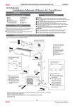
6. Printed Circuit Board Connector Wiring Diagram
Connectors
PCB (1) Control PCB
series
PCB connector
1
CN1
Connect with load
Connector for power N and L
2
CN2
3
CN3
Connector for ground
4
CN4
Connector for communicate between indoor and outdoor unit
5
CN8
6
CN9
7
CN10
Connector for four way valve coil
8
CN16
Connector for electric expansion valves
9
CN17
10
CN18
Connector for CN2,CN1 on the module board
Connector for thermistors
11
CN19
12
CN20
13
CN21
Connector for fan motor
14
CN22
Connector for DC POWER 15Vand 5V to the module board
15
CN23
16
CN24
17
CN26
Connector for communicate between the control board and the module
board
Connector to P and N of the module board
Note: 09K series needn’t connect with CN16 and CN18
11
Domestic
air conditioner
Wiring diagrams
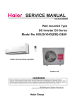
PCB (2) Module PCB
series
PCB connector
1
P (CN1)
Connect with load
Connector for capacitance board
2
N (CN5)
3
LO (CN6)
4
LI (CN7)
5
CN2
6
CN3
7
CN4
8
CN10
9
CN11
Connector for reactor
Connector for the U, V, W wire of the compressor
Connector for the DC power 5V and 15V form the control PCB
Connector for communicate between the control board and the module
board
Notes: Other Designations
PCB (1) (Control PCB)
1) FUSE 1, (25A, 250VAC); FUSE 2(1A, 250VAC)
2) LED 1 Keep light representative normal, if keep flash interval representative trouble Alarm
3) RV1, RV2, RV3 Varistor
12
Domestic
air conditioner
Wiring diagrams
PCB (1)
CN26 CN24
CN23 CN22
CN21
CN17
CN18
CN19
CN20
CN4
CN16
CN10
CN3
CN1
CN9
CN8
CN2
CN5
CN6
13
Domestic
air conditioner
Wirin
ng diagramss
PCB (2)
CN6
6
CN7
CN1
11
CN1
10
CN5
CN4
CN3
CN2
CN1
14
Dom
mestic
air co
onditioner
Functions
and control
Wiring diagrams
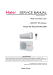
287'225:,5,1*',$*5$0
:$51,1*
02'8/(%2$5'
&$87,21
CN6
CN9 CN8
'21
7728&+&$3$&,725(9(1$)7(5
3/8*2))'$1*(52)(/(&75,&6+2&.
AC-N AC-L
5 :
CN1
:
CN7
9
8
CN4CN3CN2
CN5
%/
%/25:
WRGRXEOHZD\DLU
H[FKDQJHPRWRU
%/25:
CN1
%525%
%5
25%
CN3
CN2
25
CN26
CN22
PE
CN24
TO INDOOR UNIT
CN23
'&)$102725
3)&5($&725
7KHFDSDFLWRUUHWDLQVKLJK
YROWDJHHYHQDIWHUWKHSOXJRII
)RU\RXUVDIHW\EHVXUHWRZDLW
DWOHDVWPLQXWHVDIWHUSOXJ
RIIDQGXVHDWHVWHUWRFRQILUP
WKHYROWDJHEHWZHHQFRQQHFWRU3
DQG1RQPRGXOHERDUGLVOHVV
WKDQ'&9EHIRUHVWDUW
VHUYLFLQJ
%
CN11 CN10
MAIN CONTROL BOARD
5
AC-N AC-L
CN8 CN9
CN13
$&)$102725
(/(&75,&
(;3$16,219$/9(
32:(5
(OHFWULF
+HDWLQJ&DEOH
%˖%/$&.
5˖5('
%5˖%52:1
%/˖%/8(
:˖:+,7(
:$<9$/9(
<*˖<(//2:*5((1
Remark˖the dotted parts are
25˖25$1*(
optional for different unit.
&2035(6625',6&+$5*(
BL BL
WRVLQJOHZD\
DLUH[FKDQJHPRWRU
7(036(1625
&1
CN20 CN19 CN18 CN17
SUCTION TEMP.SENSOR
CN16
7(036(1625
7(50,1$/
%/2&.
&1
CN15 CN14
'()5267
CN10
FUSE2
AMBIENT TEMP.SENSOR
$9$&
&1
CN4
'HVFULSWLRQ
/(')ODVK
7LPHV
2XWGRRU((3520HUURU
7KHSURWHFWLRQRI,30
2YHUFXUUHQWSURWHFWLRQ
RI$&HOHFWULFLW\
&RPPXQLFDWLRQIDXOW
EHWZHHQWKH,30DQG&%'
2YHUSUHVVXUHRU2YHUKHDW
SURWHFWLRQIRUWKHFRPSUHVVRU
3RZHUYROWDJHLVWRRKLJKRUORZ
2YHUKHDWSURWHFWLRQIRU
H[KDXVWWHPSHUDWXUH
)URVWUHPRYLQJWHPSHUDWXUH
VHQVRUIDLOXUH
$PELHQWWHPSHUDWXUHVHQVRUIDLOXUH
([KDXVWWHPSHUDWXUHVHQVRUIDLOXUH
'HYLDWHIURPWKHQRUPDO
IRUWKHFRPSUHVVRU
/RRSRIWKHVWDWLRQGHWHFWHUURU
2YHUFXUUHQWRIWKHFRPSUHVVRU
2YHUFXUUHQWSURWHFWLRQIRU
VLQJOHSKDVHRIWKHFRPSUHVVRU
15
Domestic
air conditioner
Functions and control
7. Functions and Control
7.1 Main functions and control specification
7.1.1 The operation frequency of outdoor unit and its control
7.1.1.1 The operation frequency control of compressor
The operation frequency scope of compressor˖
Mode
Minimun operation frequency
Maximun operation frequency
Heating
36Hz
90 Hz
Refrigeration
36Hz
80 Hz
7.1.1.2 The starting of compressor
When the compressor is started for the first time, it must be kept under the conditions of
58Hz,88Hz for one minute (the overheating protection of the outdoor unit air-blowing temperature,
immediately decrease the frequency when the compressor is overflowing and releasing the pressure)ˈ
then it can be operated towards the target frequency. When the machine runs normally, there’s no
such process. After starting the compressor for operation, the compressor should run according to the
calculated frequency, and every determined frequency for protection should be prior to the calculated
frequency.
7.1.1.3 The speeds of increasing or decreasing the frequency of the compressor
The speed of increasing or decreasing the frequency rapidly 1 -----------1HZ/second
The speed of increasing or decreasing the frequency slowly 2 -----------1HZ/10seconds
7.1.1.4 The calculation of the compressor’s frequency
1˅The minimum/maximum frequency limitation
AˊWhile cooling: F-MAX-r is the maximum operation frequency of the compressor; F-MIN-r is the
minimum operation frequency of the compressor.
BˊWhile heating: F-MAX-d is the maximum operation frequency of the compressor; F-MIN-d is the
minimum operation frequency of the compressor.
2˅The frequency limitation which is affected by the environment temperature.
(Wh_c= environment temperature)
Heating mode:
Serial No.
Temperature scope
Frequency limitation
1
Wh_F<10.4
Max_hz8
2
Wh_F<17.6
Max_hz7
90HZ
3
Wh_F<28.4
Max_hz4
90HZ
4
Wh_F<41
5
Wh_F<50
6
Wh_F<62.6
7
Wh_F<68
Max_hz6
55HZ
8
Wh_F̱68
Max_hz3
45HZ
Max_hz5
Max_hz1
Max_hz2
90HZ
85HZ
80HZ
70HZ
Remarks: The above are the maximum frequency limitations of the complete appliance which are
affected by the environment, and they have nothing to do with the ability of the indoor unit.
Domestic air conditioner
Functions and control
Cooling/dehumidification mode:
Serial No.
Temperature scope
Frequency limitation
1
Wh_F<82.4
Max_hz1
46HZ
2
Wh_F<89.6
Max_hz2
72HZ
3
Wh_F<104
Max_hz3
80HZ
4
Wh_F<118.4
5
Wh_F̱118.4
Max_hz4
Max_hz5
65HZ
46HZ
Remarks: the above are not only the maximum frequency limitations of the complete appliance
which are affected by the environment, but also the maximum ability limitation of the system. When the
starting ability is not the maximum, its maximum frequency limitation is calculated by the following
equations:
The frequency limitation which is affected by the temperature and under the condition of actual
ability˙the actual running system ability*the maximum frequency which is limited by the temperature
and under the condition of maximum ability/the maximum designing ability of the system
T=ě˄Ti*Pi˅/ěPi
(Ti=|Tst_i the setting temperature - Tnh_i the indoor environment
temperature|; Pi˙i the ability of the indoor unit)
Cooling/dehumidification mode:
T
<1
˙1
˙2
˙3
>=4
50%
80%
120%
150%
160%
<1
˙1
˙2
˙3
>=4
50%
70%
120%
150%
170%
The percentage of the
rated frequency P
Heating mode˖
T
The percentage of the
rated frequency P
The indoor setting
airflow speed
The percentage of the
rated frequency Ki
Breeze
Low
Medium
High
Strong
Quiet
60ˁ
75%
85%
100%
120%
60%
Healthy
airflow
60%
K=ě(Ki*Pi)/ěPi
The calculation of the actual output frequency:
when there is no healthy airflow: F= F-ED-*(rated frequency)hPhK
When the healthy airflow has been set: F =F-ED-*hPhK˄airflow speed˅hK˄healthy airflow˅
Notes:
When cooling, it is needed to satisfy
F-MIN-d(compressor’s Min_hz)< F<F-MAX-d(compressor’s Max_hz)
When heating, it is needed to satisfy
F-MIN-r (compressor’s Min_hz)< F<F-MAX-r (compressor’s Max_hz)
Domestic air conditioner
Functions and control
7.1.2 The outdoor fan control (Exchange fan)
When the fan is changed among every airflow speed (including stop blowing), in order to avoid the
airflow speed from skipping frequently, it must be kept under each mode for over 30 seconds, and then
it can be changed to another mode (when cooling, the time is changed to 15 seconds).
7.1.2.1 The outdoor fan control when cooling or dehumidifying
After the compressor is started for 5 seconds, the outdoor fan is started at the medium speed at
first, after 30 seconds, it begins to control the airflow speed according to the temperature conditions of
the outdoor environment.
The temperature of the
The temperature of the outdoor
outdoor air˄Ta˅
coil˄Te˅
Ta≥86eF
——
High
——
Keeping the speed
75.2°F ≤Ta<78.8°F
——
Medium
73.4°F ≤Ta<75.2°F
——
Keeping the speed
50°F≤Ta<73.4°F
——
Low
——
Keeping the speed
59°F≤Te
Low
59°F>Te
Stop
78.8eF ≤Ta<86eF
41°F ≤Ta<50°F
Ta<41°F
Airflow speed
7.1.2.2 The outdoor fan control when heating
The temperature of the outdoor air (Ta)
Airflow speed
Low
Ta≥71.6°F
66.2°F ≤Ta<71.6°F
Keeping the speed
60.8°F≤Ta<71.6°F
Medium
57.2°F ≤Ta<60.8°F
Keeping the speed
High
Ta< 57.2°F
7.1.3 Four way control
For the details of defrosting four-way valve control, see the defrosting process.
Four way working in other ways:
Under the mode of heating, open the four-way valve, when the compressor is not started or
changed to non-heating mode, make sure the compressor is stoped for 2 minutes, and then close the
four-way valve.
7.1.4 Protection function
7.1.4.1 TTC high temperature-preventing protection
Once the machine is started, it can run TTC(air-blowing temp) overheating protection of
air-blowing, but air-blowing sensor malfunction must alarm after 4 minutes during which the
compressor is started (during the course of self-detection, there’s no such limitation)
Sensor detection methods: 100 times (one cycle of procedure run is one time, and about 5ms,
detection method for each time: continuously sampling for 8 times, then order them and take the mean
value of the middle 2 values), take the mean value.
Domestic air conditioner
Functions and control
TTC˄e)˅
Abnormal stop
230
Decreasing the frequency rapidly˄1HZ/second˅
215.6
Decreasing the frequency slowly (1HZ/10seconds)
208.4
The frequency doesn’t change.
199.4
Increasing the frequency (1HZ/10second)
194
Increasing the frequency˄1HZ/1second˅
TTC>=230°F lasts for 20 seconds. Overheating protection of air-blowing, alarm malfunction to the
indoor, others don’t last.
7.1.4.2 TC high temperature-preventing control of the indoor heating unit˖
Tpg_indoor is the highest value of the effective indoor unit (start it and it is in accord with the
running state). TC=indoor coil temp.
The indoor heat exchanger sensor tests the temperature of the indoor heat exchanger. If the
temperature is higher than 131°F, decrease the rotate speed of the compressor and do the high
temperature-preventing protection of the indoor heat exchanger; if the temperature of the indoor heat
exchanger is lower than 116.6°F, recover to the normal control.
TC(°F)
The compressor stops
Fgh_t1 149°F
Fgh_t1ˉ2
Fgh_t2ˉ2
N Decreasing the frequency rapidly
Fgh_t2 138.2°F
P Decreasing the frequency slowly
Fgh_t3
131°F
Fgh_t3ˉ2
Fgh_t4—2
Q Prohibiting increasing the frequency Fgh_t4
123.8°F
R Increasing slowly
116.6°F
Fgh_t5
Fgh_t5—2
Normal
N˖Decreasing at the speed of 1HZ/1 second
P˖Decreasing at the speed of 1Hz/10 seconds
Q˖Continue to keep the last-time instruction cycle
R˖Increasing at the speed of 1Hz/10seconds
Remarks: the outdoor unit
7.1.4.3 The control of preventing the over current of the compressor:
During the starting process of the compressor, if the current of the compressor is greater than 11A for
3 seconds, stop the compressor and alarm, after 3 minutes, start it again, if such state appears 3
times in 20 minutes, stop the compressor and alarm, and confirm the malfunction. Then continue to
run it only after the power is off.
During the starting process of the compressor, if the AC current is greater than 8.5A, the frequency of
the compressor decreases at the speed of 1HZ/second.
During the starting process of the compressor, if the AC current is greater than 8A, the frequency of
the compressor decreases at the speed of 0.1HZ/second.
Domestic air conditioner
Functions and control
During the starting process of the compressor, if the AC current is greater than 7A, the frequency of
the compressor increases at the prohibited speed.
During the starting process of the compressor, if the AC current is greater than 6.5A, the frequency of
the compressor increases at the speed of no faster than 0.1HZ/second.
7.1.4.4 The protection function of AC current:
During the starting process of the compressor, if the AC current is greater than 12A for 3 seconds,
stop the compressor and alarm, after 3 minutes, start it again, if such state appears 3 times in 20
minutes, stop the compressor and alarm, and confirm the malfunction. Then continue to run it only
after the the power is off.
During the starting process of the compressor, if the AC current is greater than 9A, the frequency of
the compressor decreases at the speed of 1HZ/second.
During the starting process of the compressor, if the AC current is greater than 8A, the frequency of
the compressor decreases at the speed of 0.1HZ/second.
During the starting process of the compressor, if the AC current is greater than 7A, the frequency of
the compressor increases at the prohibited speed.
During the starting process of the compressor, if the AC current is greater than 6.5A, the frequency of
the compressor increases at the speed of no faster than 0.1HZ/second.
Remarks: when the outdoor temperature is high, there’s compensation for AC current protection.
(1) When the outdoor environment temperature is higher than 104°F, AC current protection value
decreases by 1A.
(2) When the outdoor environment temperature is higher than122°F, AC current protection value
decreases by 2.5A.
7.1.4.5 Anti-freezing protection of the indoor heat exchanger
When cooling/heating, prevent freezing.
Tpg_indoor is the minimum value of the effective indoor unit (start it and it is in accord with the running
state).
51.8°F
//ice_temp_3+5
ice_temp_3+3
48.2°F
Increasing slowly
46.4°F //ice_temp_3+2
Keeping the frequency
ice_temp_3
ice_temp_2
44.6°F
41°F
ice_temp_1 37.4°F
32°F
44.6°F
Decreasing slowly
Decreasing rapidly ice_temp_1
Stop
When Tpg_indoorLJ ice_temp_33.8°F, the frequency of the compressor decreases at the speed of
1HZ/1second.
When Tpg_indoorLJ ice_temp_35.6°F , the frequency of the compressor decreases at the speed of
1HZ/10seconds.
When Tpg_indoor begins to rise again, and ice_temp_2İTpg_indoorİ ice_temp_37.4 °F, the frequency
of the compressor doesn’t change.
Domestic air conditioner
Functions and control
When ice_temp_3LJTpg_indoorLJice_temp_3+37.4°F , the frequency of the compressor increases at the
speed of 1HZ/10seconds.
For example, Tpg_indoorİ32°F last for 2 minutes, and then the outdoor unit will stop, and report
underload malfunction, but don’t send malfunction report to the indoor.
The compressor stops for more than 3 minutes, Tpg_indoor> ice_temp_3+35.6°F, the compressor
recovers.
7.1.4.6 The frequency limitation of modification rate
In the field which is controlled by high frequency, if the modification rate is not high enough, the
control-driven chip will enter into weak magnetic control, this will help to relieve the problem of
modification rate. If during the course of weak magnetic control, the modification rate is still not high
enough, enter into the control of decreasing frequency until the alarm of modification rate is relieved.
7.1.4.7 Temperature protection of the outdoor cooling coil
When the defrosting temperature and the sensor’s temperature are higher than 149°F , the frequency of
the compressor decreases 1hz/10seconds. Keep the frequency until it decreases to the lowest
frequency. When the temperatures are lower than 149°F and higher than 140°F , keep the frequency of
the compressor. When the temperatures are lower than 140°F , relieve the defrosting temperature
protection.
7.1.5 The control of the outdoor Electronic expansion valve (EEV)
(09K series have no this function)
In cooling mode, the EEV opening range is 90~480 steps. The EEV opening is 5 steps when unit is off.
In heating mode, the EEV opening range is 60~480 steps. The EEV opening is 45 steps when unit is
off.
After outdoor unit is off, the EEV opening keep the current on for 5 s, then open the EEV completely for
2 minutes, then become 5 steps (cooling) or 45 steps (heating).
The EEV opening will increase if SH (superheat degree) >0 while decrease if SH<0.
Adjust frequency:
If |SH|=0, 60s/ 1 step
If |SH|ı3,and ƸSH=0, 10s/ 1 step.
If 3ı|SH|ı0, 30s/ 1 step.
ƸSH= current SH- last SH
SH= Ts (suction temp)-Tc1 (indoor coil temp)-Tsh (fixed data, depend on different models, -1~2)
Domestic air conditioner
Functions and control
7.2 Value of Thermistor
Ambient Sensor, Defrosting Sensor, Pipe sensor
R77°F=10K¡f3% B77°F/122°F=3700Kf3%
Temp.(( °F ))
Max.(K )
Normal(K )
Min.(K )
-22
165.2170
147.9497
132.3678
Tolerance(°F)
28.51
35.15
-20.2
155.5754
139.5600
125.0806
28.53
35.13
-18.4
146.5609
131.7022
118.2434
28.56
35.11
-16.6
138.1285
124.3392
111.8256
28.60
35.08
-14.8
130.2371
117.4366
105.7989
28.63
35.06
-13
-11.2
122.8484
115.9272
110.9627
104.8882
100.1367
94.8149
28.67
28.71
35.04
35.01
-9.4
109.4410
99.1858
89.8106
28.74
34.99
-7.6
103.3598
93.8305
85.1031
28.76
34.95
-5.8
97.6556
88.7989
80.6728
28.80
34.93
-4
92.3028
84.0695
76.5017
28.83
34.92
-2.2
87.2775
79.6222
72.5729
28.87
34.88
-0.4
82.5577
75.4384
68.8710
28.90
34.86
-1.4
78.1230
71.5010
65.3815
28.94
34.83
-3.2
73.9543
67.7939
62.0907
28.98
34.79
29.01
34.77
-5
70.0342
64.3023
58.9863
-6.8
66.3463
61.0123
56.0565
29.05
34.74
-8.6
62.8755
57.9110
53.2905
29.08
34.72
-10.4
59.6076
54.9866
50.6781
29.12
34.68
-12.2
56.5296
52.2278
48.2099
29.16
34.65
-14
53.6294
49.6244
45.8771
29.19
34.63
15.8
50.8956
47.1666
43.6714
29.23
34.59
17.6
48.3178
44.8454
41.5851
29.28
34.56
19.4
45.8860
42.6525
39.6112
29.32
34.52
21.2
43.5912
40.5800
37.7429
29.35
34.50
23
41.4249
38.6207
35.9739
29.39
34.47
24.8
39.3792
36.7676
34.2983
29.43
34.43
26.6
37.4465
35.0144
32.7108
29.46
34.39
28.4
35.6202
33.3552
31.2062
29.52
34.36
30.2
33.8936
31.7844
29.7796
29.55
34.32
32
33.8
32.2608
30.7162
30.2968
28.8875
28.4267
27.1431
29.59
29.62
34.30
34.27
Domestic air conditioner
Functions and Control
35.6
29.2545
27.5519
25.9250
29.68
34.23
37.4
27.8708
26.2858
24.7686
29.71
34.20
39.2
26.5605
25.0851
23.6704
29.75
34.16
41
25.3193
23.9462
22.6273
29.79
34.12
42.8
24.1432
22.8656
21.6361
29.84
34.09
44.6
23.0284
21.8398
20.6939
29.88
34.05
46.4
21.9714
20.8659
19.7982
29.93
34.02
48.2
20.9688
19.9409
18.9463
29.97
33.96
50
20.0176
19.0621
18.1358
30.00
33.93
51.8
19.1149
18.2270
17.3646
30.06
33.89
53.6
18.2580
17.4331
16.6305
30.09
33.85
55.4
17.4442
16.6782
15.9315
30.15
33.82
57.2
16.6711
15.9601
15.2657
30.18
33.78
59
15.9366
15.2770
14.6315
30.24
33.73
60.8
15.2385
14.6268
14.0271
30.27
33.69
62.6
14.5748
14.0079
13.4510
30.33
33.66
64.4
13.9436
13.4185
12.9017
30.36
33.62
66.2
13.3431
12.8572
12.3778
30.42
33.57
68
12.7718
12.3223
11.8780
30.45
33.53
69.8
12.2280
11.8126
11.4011
30.51
33.49
71.6
11.7102
11.3267
10.9459
30.54
33.44
73.4
11.2172
10.8634
10.5114
30.60
33.40
75.2
10.7475
10.4216
10.0964
30.65
33.35
77
10.3000
10.0000
9.7000
30.65
33.35
78.8
9.8975
9.5974
9.2980
30.63
33.37
80.6
9.5129
9.2132
8.9148
30.56
33.34
82.4
9.1454
8.8465
8.5496
30.49
33.49
84.2
8.7942
8.4964
8.2013
30.43
33.55
86
8.4583
8.1621
7.8691
30.36
33.62
87.8
8.1371
7.8428
7.5522
30.29
33.67
89.6
7.8299
7.5377
7.2498
30.24
33.75
91.4
7.5359
7.2461
6.9611
30.16
33.80
93.2
7.2546
6.9673
6.6854
30.09
33.87
95
6.9852
6.7008
6.4222
30.02
33.93
96.8
6.7273
6.4459
6.1707
29.97
34.00
98.6
6.4803
6.2021
5.9304
29.89
34.05
100.4
6.2437
5.9687
5.7007
29.82
34.12
102.2
6.0170
5.7454
5.4812
29.75
34.20
104
5.7997
5.5316
5.2712
29.68
34.25
105.8
5.5914
5.3269
5.0704
29.61
34.32
107.6
5.3916
5.1308
4.8783
29.53
34.39
109.4
5.2001
4.9430
4.6944
29.46
34.45
111.2
5.0163
4.7630
4.5185
29.39
34.52
Domestic air conditioner
Functions and Control
113
4.8400
4.5905
4.3500
29.32
34.59
114.8
4.6708
4.4252
4.1887
29.25
34.65
116.6
4.5083
4.2666
4.0342
29.17
34.72
118.4
4.3524
4.1145
3.8862
29.10
34.79
120.2
4.2026
3.9686
3.7443
29.03
34.86
122
4.0588
3.8287
3.6084
28.94
34.92
123.8
3.9206
3.6943
3.4780
28.87
34.99
125.6
3.7878
3.5654
3.3531
28.80
35.06
127.4
3.6601
3.4416
3.2332
28.72
35.13
129.2
3.5374
3.3227
3.1183
28.63
35.20
131
3.4195
3.2085
3.0079
28.56
35.28
132.8
3.3060
3.0989
2.9021
28.49
35.33
134.6
3.1969
2.9935
2.8005
28.40
35.40
136.4
3.0919
2.8922
2.7029
28.33
35.47
138.2
2.9909
2.7948
2.6092
28.26
35.55
140
2.8936
2.7012
2.5193
28.17
35.62
141.8
2.8000
2.6112
2.4328
28.09
35.69
143.6
2.7099
2.5246
2.3498
28.00
35.76
145.4
2.6232
2.4413
2.2700
27.93
35.83
147.2
2.5396
2.3611
2.1932
27.84
35.91
149
2.4591
2.2840
2.1195
27.75
35.98
150.8
2.3815
2.2098
2.0486
27.68
36.05
152.6
2.3068
2.1383
1.9803
27.59
36.12
154.4
2.2347
2.0695
1.9147
27.52
36.21
156.2
2.1652
2.0032
1.8516
27.43
36.28
158
2.0983
1.9393
1.7908
27.34
36.36
159.8
2.0337
1.8778
1.7324
27.27
36.43
161.6
1.9714
1.8186
1.6761
27.18
36.50
163.4
1.9113
1.7614
1.6219
27.09
36.57
165.2
1.8533
1.7064
1.5697
27.00
36.64
167
1.7974
1.6533
1.5194
26.91
36.73
168.8
1.7434
1.6021
1.4710
26.82
36.81
170.6
1.6913
1.5528
1.4243
26.74
36.88
172.4
1.6409
1.5051
1.3794
26.65
36.95
174.2
1.5923
1.4592
1.3360
26.56
37.04
176
1.5454
1.4149
1.2942
26.47
37.11
177.8
1.5000
1.3721
1.2540
26.38
37.18
179.6
1.4562
1.3308
1.2151
26.29
37.27
181.4
1.4139
1.2910
1.1776
26.20
37.35
183.2
1.3730
1.2525
1.1415
26.11
37.42
185
1.3335
1.2153
1.1066
26.02
37.51
186.8
1.2953
1.1794
1.0730
25.92
37.58
188.6
1.2583
1.1448
1.0405
25.83
37.67
Domestic air conditioner
Functions and Control
190.4
1.2226
1.1113
1.0092
25.74
37.74
192.2
1.1880
1.0789
0.9789
25.65
37.83
194
1.1546
1.0476
0.9497
25.56
37.90
195.8
1.1223
1.0174
0.9215
25.45
37.99
197.6
1.0910
0.9882
0.8942
25.36
38.07
199.4
1.0607
0.9599
0.8679
25.27
38.16
201.2
1.0314
0.9326
0.8424
25.16
38.23
203
1.0030
0.9061
0.8179
25.07
38.32
204.8
0.9756
0.8806
0.7941
24.98
38.39
206.6
0.9490
0.8558
0.7711
24.87
38.48
208.4
0.9232
0.8319
0.7489
24.78
38.55
210.2
0.8983
0.8088
0.7275
24.67
38.64
212
0.8741
0.7863
0.7067
24.58
38.73
213.8
0.8507
0.7646
0.6867
24.48
38.80
215.6
0.8281
0.7436
0.6672
24.39
38.89
217.4
0.8061
0.7233
0.6484
24.28
38.98
219.2
0.7848
0.7036
0.6303
24.19
39.06
221
0.7641
0.6845
0.6127
24.08
39.15
222.8
0.7441
0.6661
0.5957
23.97
39.24
224.6
0.7247
0.6482
0.5792
23.88
39.33
226.4
0.7059
0.6308
0.5632
23.77
39.42
228.2
0.6877
0.6140
0.5478
23.67
39.49
230
0.6700
0.5977
0.5328
23.56
39.58
231.8
0.6528
0.5820
0.5183
23.47
39.67
233.6
0.6361
0.5667
0.5043
23.36
39.76
235.4
0.6200
0.5518
0.4907
23.25
39.85
237.2
0.6043
0.5374
0.4775
23.14
39.94
239
0.5891
0.5235
0.4648
23.04
40.01
240.8
0.5743
0.5100
0.4524
22.93
40.10
242.6
0.5600
0.4968
0.4404
22.82
40.19
244.4
0.5460
0.4841
0.4288
22.71
40.28
246.2
0.5325
0.4717
0.4175
22.60
40.37
248
0.5194
0.4597
0.4066
22.50
40.46
Domestic air conditioner
Functions and control
Discharging Sensor
R176e=50K¡f3%
F
B77/176°F=4450Kf3%
Temp.((°F))
Max.(KΩ)
Normal(KΩ)
Min.(KΩ)
-22
14646.0505
12061.7438
9924.4999
Tolerance(°F)
26.67
36.41
-20.2
13654.1707
11267.8730
9290.2526
26.69
36.39
-18.4
12735.8378
10531.3695
8700.6388
26.73
36.39
-16.6
11885.1336
9847.7240
8152.2338
26.74
36.37
-14.8
11096.6531
9212.8101
7641.8972
26.76
36.36
-13
-11.2
10365.4565
9687.0270
8622.8491
8074.3787
7166.7474
6724.1389
26.78
26.82
36.36
36.34
-9.4
9057.2314
7564.2244
6311.6413
26.83
36.34
-7.6
8472.2852
7089.4741
5927.0206
26.85
36.32
-5.8
7928.7217
6647.4547
5568.2222
26.89
36.30
-4
7423.3626
6235.7109
5233.3554
26.90
36.30
-2.2
6953.2930
5851.9864
4920.6791
26.92
36.28
-0.4
6515.8375
5494.2064
4628.5894
26.96
36.27
-1.4
6108.5393
5160.4621
4355.6078
26.98
36.27
-3.2
5729.1413
4848.9963
4100.3708
27.01
36.25
-5
5375.5683
4558.1906
3861.6201
27.03
36.23
-6.8
5045.9114
4286.5535
3638.1938
27.05
36.21
-8.6
4738.4141
4032.7098
3429.0191
27.09
36.21
-10.4
4451.4586
3795.3910
3233.1039
27.10
36.19
-12.2
4183.5548
3573.4260
3049.5312
27.14
36.18
-14
3933.3289
3365.7336
2877.4527
27.16
36.16
15.8
3699.5139
3171.3148
2716.0828
27.19
36.14
17.6
3480.9407
2989.2460
2564.6945
27.21
36.12
19.4
3276.5302
2818.6731
2422.6139
27.25
36.10
21.2
3085.2854
2658.8058
2289.2164
27.27
36.10
23
2906.2851
2508.9126
2163.9230
27.30
36.09
24.8
2738.6777
2368.3158
2046.1961
27.32
36.06
26.6
2581.6752
2236.3876
1935.5371
27.36
36.05
28.4
2434.5487
2112.5459
1831.4826
27.39
36.03
30.2
2296.6230
1996.2509
1733.6024
27.41
36.01
32
2167.2730
1887.0018
1641.4966
27.45
36.00
33.8
2045.9191
1784.3336
1554.7931
27.46
35.98
35.6
1932.0242
1687.8144
1473.1460
27.50
35.96
37.4
1825.0899
1597.0431
1396.2333
27.54
35.94
39.2
1724.6540
1511.6468
1323.7551
27.55
35.91
41
1630.2870
1431.2787
1255.4324
27.59
35.89
42.8
1541.5904
1355.6163
1191.0048
27.63
35.87
44.6
1458.1938
1284.3593
1130.2298
27.66
35.85
46.4
1379.7528
1217.2282
1072.8813
27.68
35.83
48.2
1305.9472
1153.9626
1018.7481
27.72
35.82
Domestic air conditioner
Functions and control
50
1236.4792
1094.3200
967.6334
27.75
35.80
51.8
1171.0715
1038.0743
919.3533
27.77
35.76
53.6
1109.4661
985.0146
873.7359
27.81
35.74
55.4
1051.4226
934.9440
830.6210
27.84
35.73
57.2
996.7169
887.6792
789.8583
27.88
35.71
59
945.1404
843.0486
751.3077
27.91
35.67
60.8
896.4981
800.8922
714.8380
27.93
35.65
62.6
850.6086
761.0603
680.3265
27.97
35.64
64.4
807.3024
723.4134
647.6580
28.00
35.60
66.2
766.4212
687.8205
616.7252
28.04
35.58
68
727.8172
654.1596
587.4271
28.08
35.56
69.8
691.3524
622.3161
559.6694
28.11
35.53
71.6
656.8979
592.1831
533.3634
28.15
35.51
73.4
624.3328
563.6604
508.4261
28.18
35.47
75.2
593.5446
536.6540
484.7796
28.22
35.46
77
564.4275
511.0760
462.3510
28.24
35.42
78.8
536.9865
486.9352
441.1516
28.27
35.40
80.6
511.0105
464.0500
421.0258
28.31
35.37
82.4
486.4151
442.3499
401.9146
28.35
35.35
84.2
463.1208
421.7683
383.7626
28.38
35.31
86
441.0535
402.2430
366.5175
28.42
35.29
87.8
420.1431
383.7151
350.1301
28.45
35.26
89.6
400.3242
366.1295
334.5542
28.49
35.24
91.4
381.5350
349.4341
319.7460
28.53
35.20
93.2
363.7176
333.5801
305.6645
28.58
35.17
95
346.8176
318.5216
292.2709
28.62
35.15
96.8
330.7839
304.2151
279.5286
28.65
35.11
98.6
315.5682
290.6199
267.4031
28.69
35.08
100.4
301.1254
277.6976
255.8620
28.72
35.06
102.2
287.4128
265.4119
244.8745
28.76
35.02
104
274.3905
253.7288
234.4118
28.80
34.99
105.8
262.0206
242.6161
224.4465
28.83
34.95
107.6
250.2676
232.0436
214.9529
28.87
34.93
109.4
239.0983
221.9825
205.9065
28.92
34.90
111.2
228.4809
212.4060
197.2844
28.96
34.86
113
218.3860
203.2887
189.0648
28.99
34.83
114.8
208.7855
194.6066
181.2273
29.03
34.79
116.6
199.6531
186.3369
173.7524
29.07
34.77
118.4
190.9639
178.4584
166.6217
29.12
34.74
120.2
182.6945
170.9508
159.8181
29.16
34.70
122
174.8228
163.7951
153.3249
29.19
34.66
123.8
167.3280
156.9733
147.1268
29.25
34.63
125.6
160.1904
150.4683
141.2090
29.28
34.59
127.4
153.3914
144.2641
135.5577
29.32
34.56
129.2
146.9136
138.3454
130.1598
29.35
34.52
Domestic air conditioner
Functions and control
131
140.7403
132.6980
125.0027
29.41
34.48
132.8
134.8559
127.3081
120.0746
29.44
34.45
134.6
129.2457
122.1630
115.3645
29.48
34.41
136.4
123.8956
117.2504
110.8618
29.53
34.38
138.2
118.7926
112.5589
106.5564
29.57
34.34
140
113.9241
108.0776
102.4388
29.62
34.30
141.8
109.2784
103.7961
98.5000
29.66
34.27
143.6
104.8443
99.7046
94.7315
29.70
34.21
145.4
100.6112
95.7939
91.1253
29.75
34.18
147.2
96.5692
92.0553
87.6735
29.79
34.14
149
92.7088
88.4805
84.3690
29.84
34.12
150.8
89.0211
85.0614
81.2048
29.88
34.07
152.6
85.4976
81.7908
78.1744
29.93
34.02
154.4
82.1303
78.6615
75.2715
29.97
33.98
156.2
78.9116
75.6668
72.4902
30.02
33.94
158
75.8343
72.8004
69.8249
30.06
33.91
159.8
72.8916
70.0561
67.2703
30.11
33.85
161.6
70.0770
67.4283
64.8213
30.15
33.82
163.4
67.3844
64.9115
62.4731
30.20
33.78
165.2
64.8080
62.5006
60.2211
30.24
33.73
167
62.3423
60.1906
58.0609
30.29
33.69
168.8
59.9821
57.9770
55.9885
30.34
33.66
170.6
57.7223
55.8552
53.9998
30.38
33.60
172.4
55.5583
53.8210
52.0912
30.43
33.57
174.2
53.4856
51.8706
50.2591
30.47
33.51
176
51.5000
50.0000
48.5000
30.47
33.51
177.8
49.7063
48.2057
46.7083
30.47
33.53
179.6
47.9835
46.4842
44.9911
30.40
33.60
181.4
46.3286
44.8323
43.3452
30.33
33.62
183.2
44.7385
43.2468
41.7672
30.27
33.71
185
43.2105
41.7248
40.2540
30.20
33.78
186.8
41.7386
40.2604
38.7996
30.15
33.84
188.6
40.3241
38.8545
37.4048
30.07
33.91
190.4
38.9643
37.5045
36.0668
30.00
33.96
192.2
37.6569
36.2078
34.7831
29.95
34.03
194
36.3996
34.9622
33.5513
29.88
34.09
195.8
35.1903
33.7653
32.3689
29.80
34.14
197.6
34.0269
32.6151
31.2338
29.73
34.21
199.4
32.9075
31.5096
30.1438
29.66
34.29
201.2
31.8302
30.4467
29.0970
29.61
34.34
203
30.7933
29.4246
28.0915
29.53
34.41
204.8
29.7950
28.4417
27.1254
29.46
34.47
206.6
28.8337
27.4961
26.1970
29.39
34.54
208.4
27.9078
26.5864
25.3048
29.32
34.59
210.2
27.0160
25.7110
24.4470
29.25
34.66
Domestic air conditioner
Functions and control
212
26.1569
24.8685
23.6222
29.17
34.74
213.8
25.3290
24.0574
22.8291
29.10
34.79
215.6
24.5311
23.2765
22.0662
29.03
34.86
217.4
23.7620
22.5245
21.3323
28.96
34.93
219.2
23.0205
21.8002
20.6261
28.89
34.99
221
22.3055
21.1025
19.9465
28.81
35.06
222.8
21.6159
20.4303
19.2924
28.74
35.13
224.6
20.9508
19.7825
18.6626
28.67
35.19
226.4
20.3091
19.1582
18.0563
28.60
35.26
228.2
19.6899
18.5564
17.4723
28.53
35.33
230
19.0924
17.9761
16.9098
28.44
35.40
231.8
18.5157
17.4166
16.3680
28.36
35.47
233.6
17.9590
16.8769
15.8458
28.29
35.53
235.4
17.4214
16.3564
15.3427
28.22
35.60
237.2
16.9023
15.8542
14.8577
28.13
35.67
239
16.4010
15.3696
14.3902
28.06
35.74
240.8
15.9167
14.9020
13.9394
27.99
35.82
242.6
15.4489
14.4506
13.5047
27.91
35.89
244.4
14.9968
14.0149
13.0855
27.82
35.94
246.2
14.5599
13.5942
12.6811
27.75
36.01
248
14.1376
13.1879
12.2909
27.66
36.09
249.8
13.7294
12.7955
11.9144
27.59
36.16
251.6
13.3347
12.4165
11.5510
27.50
36.23
253.4
12.9531
12.0503
11.2003
27.43
36.30
255.2
12.5840
11.6965
10.8617
27.36
36.37
257
12.2270
11.3545
10.5348
27.27
36.45
258.8
11.8817
11.0240
10.2191
27.18
36.52
260.6
11.5475
10.7046
9.9142
27.10
36.59
262.4
11.2242
10.3957
9.6197
27.01
36.66
264.2
10.9112
10.0970
9.3352
26.94
36.73
266
10.6084
9.8082
9.0602
26.85
36.81
267.8
10.3151
9.5288
8.7945
26.76
36.88
269.6
10.0312
9.2586
8.5378
26.69
36.95
271.4
9.7563
8.9971
8.2895
26.60
37.04
273.2
9.4901
8.7441
8.0495
26.51
37.11
275
9.2322
8.4993
7.8175
26.44
37.18
276.8
8.9824
8.2623
7.5931
26.35
37.26
278.6
8.7404
8.0329
7.3760
26.26
37.33
280.4
8.5059
7.8108
7.1660
26.17
37.40
282.2
8.2787
7.5958
6.9629
26.08
37.47
284
8.0584
7.3875
6.7664
26.01
37.56
Domestic air conditioner
Dimensinal drawings
8.Dimensional drawings
2.76
2.57
0.84
1.78
0.24
0.22
0.18
0.84
2.57
9.Center of gravity
2.57
0.84
1
0.39
0.84
1.78
Domestic air conditioner
System configuration
Installation Manual of Room Air Conditioner
Preparation
Necessary Tools for Installation
Selection of Installation Place
Indoor Unit - Select a location that is
ƽ Torque wrench
(0.67 in,0.87in,1.02in )
ƽ Hammer
ƽ Nipper
ƽ Hacksaw
ƽ Robust not causing vibration, where the unit can be supported s ufficiently.
ƽ Not affected by heat or steam generated in the vicinity, and where the inlet and outlet of
ƽ Pipe cutter
ƽ Hole core drill
ƽ Flaring tool
ƽ Spanner(0.67,0.75 and 1.02in )
ƽ Gas leakage detector or
ƽ Knife
ƽ Measuring tape
the unit are not disturbed.
ƽ Possible to drain easily, and where piping can be connected with the outdoor unit.
ƽ Where conditioned air can be spread in a room evenly.
ƽ Place where the distance of more than lm from televisions, radios, wireless apparatuses
ƽ Reamer
soap-and-water solution
and fluorescent lamps 3 feet or approximately.
ƽ In the case of fixing the remote controller on a wall, place where the indoor unit can
receive signals when the fluorescent lamps in the room are in use.
Power Source
Outdoor Unit - Select a location that is
ƽ Less affected by rain or direct sunlight and is sufficiently ventilated.
ƽ Strong enough to bear the unit, where vibration and noise are not increased.
ƽ Not causing a nuisance to neighbors due to discharged air or noise.
ƽ A distance marked Q is available as illustrated in the below figure.
ƽ All wiring to the unit must be in accordance with the National Electric code
and local ordinances.
Drawing for the installation of indoor and outdoor units
The models adopt HFC free refrigerant R410A
Attention must be paid to
the pitch of drain hose
more than 5cm
(2 inches)
Optional parts for piping
A Non-adhesive tape
B Adhesive tape
C Saddle (L.S) with screws
Connecting electric cable
D
for indoor and outdoor
E Drain hose
G
more than
10cm
(4 inches)
F Insulating material
G Piping hole cover
Arrangement of piping
directions
more than10cm
(4 inches)
Rear left
F
A
Rear
right
Left
Floor fixing dimensions of the outdoor unit
(Unit: inch)
Z
X
Y
X
Right
C
Below
Dimensions(inches)
Model
more than10cm
more than10cm
x
y
z
(4 inches)
(4 inches)
HSU12VHGL-W
ƽ The marks from A to
G in the figure are the
name of the parts.
ƽ The distance between
the indoor unit and the
floor should be more
than 2m or 6 feet.
D
19 2/3
10 1/16
Fixing of outdoor unit
ƽ Fix the unit to concrete or block with bolts
E
(10mm) securely.
ƽ When fitting the unit to wall surface, roof or
more than 60cm
(24 inches)
5 1/2
ƽ
rooftop, fix the unit securely in consideration
of earthquake and strong wind.
If vibration may affect the house, fix the unit
by attaching a vibration-proof mat.
more than 15cm
(5 7/8 inches)
The above picture is for reference only. Your product may look different.
Read this manual before installation
Explain the operation of the unit to the user according to this manual
Domestic air conditioner
31
System configuration
Accessory parts
Remote controller (1)
Drain hose (1)
AAA dry battery (2)
Cushion (4)
Mounting plate (1)
Drain-elbow (1)
Making a Hole on the Wall and Fitting the Piping Hole Cover
ƽ Make a hole of B mm / inches in diameter, slightly descending to outside the wall.
ƽ Install piping hole cover and seal it off with putty after installation
Pitch downward for drainage
Wall hole
09k/12k : B= 60mm(2 3/8 inches)
18k/24k : B=70mm(2 3/4 inches)
ØBmm
Plastic cap (4)
Ø4X25 Screw (4)
Pipe supporting plate (1)
Indoor side
Selection of pipe
Model
Liquid pipe (Ø)
(Section of wall hole)
6.35mm (1/4 ")
G Piping hole pipe
Gas pipe (Ø)
HSU12VHGL-W
Outdoor side
Thickness of wall
Installation of the Indoor Unit
9.52mm (3/8 ")
Drawing of pipe
NOTE˖The thickness of the pipe must be 0.8mm(1/16”) at least.
[ Rear piping ]
ƽ Draw pipes and the drain hose, then fasten them with the adhesive tape
Indoor unit
[ Left・Left-rear piping ]
ƽ In case of left side piping, cut away, with a nipper, the lid for left piping.
ƽ In case of left-rear piping, bend the pipes according to the piping direction to
the mark of hole for left-rear piping which is marked on insulation materials.
Fitting of the Mounting Plate and Positioning of the wall Hole
1. Insert the drain hose into the carity of heat insulation materials of indoor unit.
2. Insert the indoor/outdoor electric cable from backside of indoor unit, and pull it
out on the front side, then connect them.
3. Coat the flaring seal face with refrigerant oil and connect pipes.
Cover the tubing connection with insulation materials closely, and with adhesive
tape.
When the mounting plate is first fixed
1. Carry out, based on the wall studs or lintels, a proper leveling for the plate
to be fixed against the wall, then temporarily fasten the plate with one nail.
2. Ensure the proper level of the plate, by hanging a thread with a
weight from the central top of the plate, then fasten the plate.
Indoor/outdoor electric cable
3. Find the wall hole location A using a measuring tape
Insulation
material
Lid for right
piping
B= 60mm
Lid for left piping
B= 60mm
Piping
Pipe supporting
plate
Drain hose
Lid for under piping pipe
A=145mm
30mm
30mm
Fix with adhesive tape
A=145mm
ƽ Indoor/outdoor electric cable and drain hose must be bound with refrigerant
piping with adhesive.
[ Other direction piping ]
A=125mm
30mm
B= 70mm
ƽ Cut away, with a nipper, the lid for piping according to the piping direction and
then bend the pipe according to theposition of wall hole. When bending, be
careful not to crush pipes.
ƽ Make sure that the wires connecting the indoor and outdoor units are not covered
by the refrigeration piping insulation and are long enough to connect to the terminal
block on the indoor unit.
Fixing the indoor unit body
Pay attention to the following points before installation of machine:
1. Take out cushion blocks on
the left and right angle beads
as shown in the following
Figure.
ƽ Hang the unit body onto the upper notches of the
mounting plate. Move the body from side to side to verify
its secure fixing.
ƽ In order to fix the body onto the mounting plate,hold up
the body from the underside and then put it down
perpendicularly.
mounting plate
Unloading of indoor unit body
2. Remove 2 gaskets under the
cross-flow fan.
ƽWhen you unload the indoor unit,please use
your hand to raise the body , then
lift the bottom of the body outward
slightly and lift the unit until
it leaves the mounting plate.
3. Clean the burr on the surface of fracture to avoid the power
wire from being scratched after removing the virtual opening
of the outgoing line slot on the case by hands in indoor
power-on process.
agraffe
32
mounting plate
Domestic air conditioner
System configuration
Connecting the indoor/outdoor Electric Cable
Outdoor unit
Installation of Outdoor Unit
Removing the wiring cover
Install according to the instructions on the 1st page of this manual
ƽ Remove terminal cover at right bottom corner of indoor unit, then take off
wiring cover by removing its screws.
Connection of pipes
ƽ When bending the interconnect tubing, ensure the radius is at least 1 1/4" to 1 3/4",
When connecting the cable after installing the indoor unit
30mm to 40mm to ensure against crushing the tubing.
ƽ Connecting the pipe of gas side first makes working easier.
ƽ Ensure the interconnecting tubing is approved for R410A.
1. Insert the cable from the outside into the unit through the same
hole that has the interconnecting tubing.
Half union
Forced fastening without careful centering may
damage the threads and cause a leakage of gas.
Flare nut
2. Pull out the cable on the front side, and connect the cable
making a loop.
When connecting the cable before installing the indoor unit
Pipe Diameter(ǿ)
Fastening torque
Liquid side6.35mm(1/4")
18N.m/13.3Ft.lbs
Liquid/Gas side9.52mm(3/8") 42 N.m/30.1Ft.lbs
ƽ
ƽ
ƽ
Insert the cord from the back side of the unit, then pull it out on the front side.
Spanner
Torque wrench
Fasten the unit wire harness to the conduit holder using the lock nut.
Gas side 12.7mm(1/2")
55N.m/40.6Ft.lbs
Gas side 15.88mm(5/8")
60 N.m/44.3Ft.lbs
Position the conduit holder to its original state using screw.
Ensure that no dirt or debris enters the tubing. The standard tubing length is 25 ft/7.5M.
If a different length is required, adjust the refrigerant amount by 1/2 oz/ft, 50 g/M for the
9k, 12k and 18k models. For the 24k model, adjust by 1/2 oz/ft, 50 g/M.Before opening
the service valves, evacuate the interconnecting tubing and indoor unit. Follow the
instruction in section 5 on page 4.
CAUTION
Note
When connecting the cable, confirm the terminal number of indoor and
outdoor units carefully. If wiring is not correct, the unit will not operate
properly and could cause a defect.
Outdoor unit
Indoor unit
B
B
Outdoor unit
A
Indoor unit
Indoor unit
A
Outdoor unit
4wire 14AWG
(4G0.75mm )
Amax
• Max.Elevation:
= 32.8ft / 10m (09k / 12k)
Control Wiring
Outdoor unit
B
HSU12VHGL-W
A
Power cable:
•
Oil trap
Indoor unit
Length: Bmax
• Max.
= 50ft / 15m (09k / 12k)
= 83.3ft / 25m (18k / 24k)
3wire with ground 14AWG
1. If the supply cord is damaged, it must be replaced by the manufacturer or its
service agent or a similar qualified person. The type of connecting wire is
H05RN-F or H07RN-F.
2. If the fuse on PC board is broken please change it with the type of
T.3.15A/250VAC (Indoor), T.25A/250VAC (Outdoor).
3. The wiring method should be in line with the local wiring standard.
4. Use an HVACR circuit breaker or time delay fuse.
= 50ft / 15m (18k / 24k)
In case the elevation A is more
than 16.4ft / 5m, oil trap shoud be
installed every 5~7m(16.4ft-23ft)
Cutting and Flaring Work of Piping
ƽ Pipe cutting is carried out with a pipe cutter and burs must
ƽ After inserting the flare nut, flaring work is carried out.
A
be removed.
Flare tool for R410A
Conventional flare tool
Clutch-type
clutch-type(Rigid-type) Wing-nut type (Imperial-type)
0~0.5mm
0~1/51 inch
1.5~2.0mm
1/17 ~1/8 inch
1.0~1.5mm
3/76 ~1/17 inch
1.Cut pipe
Flare tooling die
2.Remove burs
4.Flare pipe
3.Insert the flare nut
Correct
Incorrect
Lean
33
Damage of flare
Crack
Partial
Too outside
Domestic air conditioner
System configuration
ƽ
ƽ
ƽ
Connection
Loosen the screws on terminal block and insert the wires fully into terminal
block, then tighten the screws.
If wiring is not correct, the unit will not operate properly and it could cause a
defect in the unit.
Fix the cable with a clamp.
Power Source Installation
ƽ The power source must be exclusively used for air conditioner.
ƽ In the case of installing an air conditioner in a moist place, please install an earth leakage breaker.(GFCI)
ƽ For installation in other places, use an HVACR circuit breaker of time delay fuse.
Attaching Drain-Elbow
On Drainage
ƽ Please install the drain hose and ensure downward flow.
ƽ Please don’t do the drainage as shown below.
ƽ If the drain-elbow is used,
please attach as shown in figure.
(Note: Only for heat pump unit.)
1.
Less than
5cm
Purging Method:To use vacuum pump
It becomes The end is imm- It waves. The gap with the
There is the bad
high midway. ersed in water.
ground is too small. smell from a ditch
Detach the service port’s cap of 3-way valve, and the valve cap for 2-way valve
and 3-way valve. Connect the service port to the low side of the gauge manifold
and connect the vacuum pump to the center port of the manifold.
ƽ Please pour water in the drain pan of the indoor unit, and confirm that drainage
is proper.
2. Open the handle on the low side of the gauge manifold and operate vacuum pump.
ƽ In case that the attached drain hose is in a room, please
apply insulation to
to the hose to prevent condensation.
3. Vacuum the tubing for at least 15 minutes. The vacuum level on the low side gauge
should be 29.9 in of Hg, 76 cm of Hg, 0.1 MPa. when vacuuming is complete, close
the valve on the manifold and turn off the vacuum pump. The vacuum level should
hold for 1-2 minutes. If the vacuum level does not hold, check the flared connections
and repeat this step.
Ƶ Refrigerant charge label
Contains fluorinated greenhouse gases
covered by the Kyoto Protocol
4. Open the 2-way valve 1/4 turn. After 5-6 seconds, close the valve and inspect for
leaks with a leak detector or soap solution.
5. No gas leakage? Go to step 6.
In case of a leak, try tightening the flare connections to fix the leak. If the
leak stops, go to step 6. If the leak continues, check the flare connections
and repair as needed, then go back to step 3. then proceed step 6. If leak
continues, remove the refrigerant used for the leakage check and flare
tubes again. Repeat vacuum and leak and if no leakage, proceed to step 6.
R410A
1=
kg
2
2=
kg
1+2=
kg
1
F
A
B
C
D
E
6. Detach the charge hose from the service port, open 2-way valve and 3-way
This product contains fluorinated greenhouse gases covered by
the Kyoto Protocol. Do not vent into the atmosphere.
Refrigerant type:R410A
GWP* value:1975
GWP=global warming potential
Please fill in with indelible ink,
•1
the factory refrigerant charge of the product
•2
the additional refrigerant amount charged in the field and
• 1+2 the total refrigerant charge
on the refrigerant charge label supplied with the product.
The filled out label must be adhered in the proximity of the product
charging port (e.g. onto the inside of the stop value cover).
A contains fluorinated greenhouse gases covered by the Kyoto
Protocol
B factory refrigerant charge of the product: see unit name plate
C additional refrigerant amount charged in the field
D total refrigerant charge
E outdoor unit
F refrigerant cylinder and manifold for charging
valve completely.
7. To prevent the gas
leakage, replace the service port and valve caps.
8. After attaching the caps, check for leakage around the caps.
Step 1.
Step 2.
2-way valve Liquid Side
3-way valve Gas Side
Open
Gaugemanifold(for R410A)
Gauge manifold
Step 3.
Close
Vacuum pump
Tube(for R410A)
Step 4.
Step 6.
2-way valve
2-way valve
3-way valve
3-way valve
O
Open 90
Ƶ Check for Installation and Test Run
Step 7.
Ƶ Please kindly explain to our customers how to operate
through the instruction manual.
2-way valve
3-way valve
2-way valve 3-way valve
Check Items for Test Run
Put check mark
in boxes
Gas leak from interconnecting tubing?
Installation is on the interconnecting tubing?
Are the connecting wirings of indoor and outdoor firmly
inserted to the terminal block?
Is the connecting wiring of indoor and outdoor firmly fixed?
Is drainage securely carried out?
Is the ground wire securely connected?
Is the indoor unit securely fixed?
Is power source voltage the local codes?
Is there any noise?
Are the lights near the unit working normally?
Are cooling and heating (when in heat pump) performing normally?
Is the operation of room temperature control normal?
Valve cap
Valve cap
Service port cap
CAUTION
ƽ If the refrigerant of the air conditioner leaks, it is necessary to discharge all the
refrigerant. Repair the leak, vacuum the unit then charge the liquid refrigerant
into air conditioner according to the amount marked on the name plate.
ƽ Please do not let other cooling medium, except specified one (R410A), or air
enter into the cooling circulation system. This could cause high pressure and
could cause a leak and lead to personal injuries.
34
Domestic air conditioner
Installations
11 Service Diagnosis
11.1 Caution for Diagnosis
The operation lamp flashes when any of the following errors is detected.
1. When a protection device of the indoor or outdoor unit is activated or when the thermistor malfunctions,
disabling equipment operation.
2. When a signal transmission error occurs between the indoor and outdoor units. In either case, conduct the
diagnostic procedure described in the following pages.
11.2 Parameter of primary electronic appliance
name
parameter
picture
Rated voltage:220-230V
Compressor
Rated current:4.8A
Rated frequency: 50/60HZ
Rated voltage:220-230V
Fan motor
Rated current:0.2A
Rated frequency: 50/60HZ
Rated voltage:220-230V
Reactor
Rated current:10.5A
Rated frequency: 50/60HZ
Rated voltage:220-230V
4-way valve
Rated current:0.1A
Rated frequency: 50/60HZ
35
Domestic
air conditioner
Installations
11.3 Problem Symptoms and Measures
Symptom
None of the units
operates
Operation
sometimes stops.
Check Item
Check the power supply.
Check the indoor PCB
Check the power supply.
Details of Measure
Check to make sure that the rated voltage is supplied.
Check to make sure that the indoor PCB is broken
A power failure of 2 to 10 cycles can stop air conditioner
operation.
Set the units to cooling operation, and compare the
Check for faulty operation
Equipment
operates but
does not cool, or
does not heat
(only for heat
pump)
temperatures of the liquid side connection pipes of the
of the electronic
connection section among rooms to check the opening and
expansion valve.
closing operation of the electronic expansion valves of the
individual units.
Diagnosis by service port
pressure and operating
Check for insufficient gas.
current.
Large operating
noise and
vibrations
Check the installation
condition.
Check to make sure that the required spaces for
installation (specified in the Technical Guide, etc.) are
provided.
36
Domestic
air conditioner
Service diagnosis
11
Code indication
Indoor
displaying
panel code
indication
Indoor and
Outdoor
Indoor Malfunction
Malfunction
Reference
fault description
Page
(LED1 flash
times)
Communication fault between indoor and
E7
15
E1
--
Room temperature sensor failure
Page38
E2
--
Heat-exchange sensor failure
Page38
E4
--
Indoor EEPROM error
Page47
E14
--
Indoor fan motor malfunction
Page39
F12
1
Outdoor EEPROM error
Page47
F1
2
The protection of IPM
Page43
3
Overcurrent protection of AC electricity
F22
Outdoor
Outdoor
outdoor units
for the outdoor model
Communication fault between the IPM and
Page48
Page52
F3
4
F19
6
F27
7
F4
8
F8
9
Outdoor DC fan motor fault
Page42
F21
10
Defrost temperature sensor failure
Page38
F7
11
Suction temperature sensor failure
Page38
F6
12
Ambient temperature sensor failure
Page38
F25
13
Discharge temperature sensor failure
Page38
F13
16
Short of refrigerant
Page54
F11
18
deviate from the normal for the compressor
Page51
F28
19
Loop of the station detect error
Page51
/
21
Over load protection of indoor system
Page53
F2
24
Overcurrent of the compressor
Page52
F23
25
E9
21
outdoor PCB
Power voltage is too high or low
Page50
Compressor is lock-rotor or stopped
momentary
Overheat protection for Discharge
temperature
Overcurrent protection for single-phase of the
compressor
High work-intense protection
37
Page45
Page51
Page46
Page52
Page54
Domestic air conditioner
Installations
11.4.1 Thermistor or Related Abnormality
E1: Room temperature sensor failure
Indoor display
E2: Heat-exchange sensor failure
LED1 flash 10 times˖Defrost temperature sensor failure
LED1 flash 11 times˖Suction temperature sensor failure
Outdoor display
LED1 flash 12 times˖Ambient temperature sensor failure
LED1 flash 13 times˖Discharge temperature sensor failure
Method of
malfunction detection
The temperatures detected by the thermistors are used to determine thermistor errors
Malfunction detection
conditions
when the thermistor input is more than 4.92V or less than 0.08V during compressor
operation.
Note: The values vary slightly in some models
Supposed causes
Troubleshooting
■ Faulty connector connection
■ Faulty thermistor
■ Faulty PCB
* Caution Be sure to turn off power switch before connect or disconnect connector,
or else
parts damage may be occurred.
YES
Check the connector connection,
whether if it loose or misplug
Re-connect
NO
*Thermistor resistance check
NO
Is the resistance is conformity
Replace the thermistor
with normal temperature
YES
Replace the indoor PCB
Thermistor resistance check method:
Remove the connector of the thermistor on the PCB, and measure the resistance of thermistor using tester. The
relationship between normal temperature and resistance is shown in the value of indoor thermistor.
Domestic air conditioner
Installations
11.4.2 EEPROM abnormal
Indoor Display
outdoor display
E4:
indoor EEPROM error
F12: Outdoor EEPROM error; Outdoor LED1 flash 1 times
Method of
malfunction detection
The Data detected by the EEPROM are used to determine MCU
Malfunction detection
conditions
when the data of EEPROM is error or the EEPROM is damaged
Supposed causes
■Faulty EEPROM data
■Faulty EEPROM
■Faulty PCB
Troubleshooting
* Caution Be sure to turn off power switch before connect or disconnect connector,
or parts damage may be occurred.
Replace the indoor or outdoor mainboard
39
Domestic
air conditioner
Installations
11.4.3 Indoor AC fan motor malfunction
Indoor Display
E14
Method of
malfunction detection
The fan speed detected by the Hall IC during fan motor running which is used to
determine the fan motor operating
Malfunction detection
conditions
When there is no fan speed feedback signal within 2 minutes
Supposed causes
Troubleshooting
Operation halt due to breaking of wire inside the fan motor.
Fan motor overheat protection
Operation halt due to breaking of the fan motor lead wires
Detection error due to faulty indoor unit PCB
* Caution
Be sure to turn off power switch before connect or disconnect connector, or else parts
damage may be caused
NO
Check whether terminals
Pull out the terminals on the indoor
mainboard and reinsert them.
on indoor pcb is well?
YES
Electrify the machine again and turn it on in the cooling operation,
Measure voltage between the positions 1and 3 of Terminal CN5 on
the indoor PCB
the voltage is about 90-220vac
YES
Measure whether there is voltage pulse(0-5VDC)
YES
check whether motor can run
between the positions middle wire and black wire
of Terminal CN2 on the indoor PCB
when turn on the unit
Is it ok?
YES
the indoor motor is damaged and need replace
the indoor pcb is damaged and need replace
40
Domestic air conditioner
Installations
11.4.4 Outdoor DC fan motor fault
Outdoor diplay
Method of
malfunction detection
Malfunction detection
conditions
Supposed causes
LED1 flash
9 times
DC fan motor is detected by checking
the fan running condition and so on
when the data of EEPROM
is error or
the EEPROM
is damaged
■DC fan motor protection dues to the DC fan motor faulty
■DC fan motor protection dues to faulty PCB
* Caution
Troubleshooting
Be sure to turn off power switch before connect or disconnect connector,
or parts damage
may be occurred.
41
Domestic
air conditioner
Installations
Check whether Terminal on the outdoor
mainboard is well inserted. Is it normal?
NO
Reinsert the terminals
YES
Electrify the machine again and turn it
NO
on in the Cool state with the remote
controller. check whether motor can
run˛
Measure the voltage between 1 and 3 of the terminal of
fan motor on the mainboard about DC310V, Measure
YES
the voltage between 3 and 4 of the terminal about
DC15V. Measure the voltage between 5 and 3 of the
Measure the voltage between 3 and 6 of
terminal about 1-6v.
the terminal about 0-5v.
YES
Is it normal?
Is it normal?
NO
YES
NO
The motor of the outdoor unit is damaged
and needs replacing.
The mainboard of the outdoor unit is
damaged and needs replacing
42
Domestic
air conditioner
Installations
11.4.5 IPM protection
Outdoor diplay
LED1 flash 2 times
Method of
malfunction detection
IPM protection is detected by checking the compressor running condition and so on
Malfunction detection
conditions
■The system leads to IPM protection due to over current
■The compressor faulty leads to IPM protection
■circuit component of IPM is broken and led to IPM protection
Supposed causes
■IPM protection dues to the compressor faulty
■IPM protection dues to faulty PCB of IPM module
■Compressor wiring disconnected
Troubleshooting
* Caution
Be sure to turn off power switch before connect or disconnect connector,
or else
parts damage may be occurred..
Electrify the machine again and turn it on
with the remote controller,If malfunctions
<(6
are reported before or upon the compressor
IPM Module is damaged and
needs replacing.
being started up,
Malfunction unsolved
12
The
compressor
is
started
normally,
but
malfunctions are reported after it has run for some
time.
1ǃThe system may have been over or under charged with gas, which can be judged through the pressure of the
measuring system.
2ǃThe shaft of compressor is seized and the compressor needs replacing.
43
Domestic
air conditioner
Installations
11.4.6 Over-current of the compressor
LED1 flash 3 or 24 or 25 times
Outdoor diplay
Method of
malfunction detection
Malfunction
detection
conditions
Supposed
causes
Troubleshooting
he current of the compressor is too high
when the IPM Module is damaged or the compressor is damaged.
voltage is too low or too high
■Faulty IPM Module
■ Faulty compressor
■Faulty power supply
power supply
* Caution
Be sure to turn off power switch before connect or disconnect connector, or parts
damage may be occurred...
Electrify the machine again and turn it on
with the remote controller, If malfunctions
YES
are reported before or upon the compressor
IPM Module is damaged and
needs replacing.
being started up,
NO
The compressor is started normally, but
malfunctions are reported after it has
YES
Repair the power supply
run for some time. Check the power
supply is too low or too high
NO
NO
the system may have been over or under charged
with gas, which can be judged through the
pressure of the measuring system.
Domestic
44
air conditioner
Installations
11.4.7 The communication fault between IPM and outdoor PCB
LED1 flash 4 times
Outdoor diplay
Method of
malfunction detection
Communication is detected by checking the IPM module and the outdoor PCB
Malfunction detection
conditions
■The outdoor PCB broken leads to communication fault
■The IPM module broken leads to communication fault
Supposed causes
Troubleshooting
■The outdoor PCB is broken
■The IPM module is broken
■Communication wiring disconnected
* Caution
Be sure to turn off power switch before connect or disconnect connector,
or else
parts damage may be occurred
1) Check whether Terminal CN23 and CN24 on the outdoor mainboard
CN10 and CN11 on IPM module
2) Check whether the connected wire between IPM and outdoor
1) Pull out and reinsert the terminals.
NO
Are they good?
YES
2) Replace connected wire
Malfunction unsolved
Electrify the machine again and turn it
on, Check whether the voltage between
1 and 2 of Terminal CN23 is about DC5V,
Check whether the voltage between2
YES
Replace the outdoor IPM module
with a new one.
and 3 of Terminal CN23 is about DC15V,
NO
Replace the outdoor mainboard with a new one
45
Domestic
air conditioner
Installations
11.4.8 Power Supply Over or under voltage fault
LED1 flash 21 times
Outdoor diplay
The power supply is over voltage
Method of
malfunction detection
An abnormal voltage rise or fall is detected by checking the specified voltage detection
Malfunction
detection
conditions
An voltage signal is fed from the voltage detection circuit to the microcomputer
Supposed
causes
Troubleshooting
■Supply voltage not as specified.
■The IPM module is broken.
■The outdoor PCB is broken.
* Caution
Be sure to turn off power switch before connect or disconnect connector, or else
parts damage may be occurred.
Electrify the machine again and turn it on with
the remote controller. Check whether the
compressor is started normally
YES
Maybe there is some disturbance
Is it ok?
NO
Test the outdoor power supply
YES
(+310VDC) with a multimeter.
Change the IPM module
check whether the power
is >150 V or <390V?
NO
~230 is ok?
YES
Change the IPM module
NO
This question may be caused by the power. Repair
the power supply.
46
Domestic
air conditioner
Installations
11.4.9 Overheat Protection For Discharge Temperature
LED1 flash 8 times
Outdoor diplay
Method of
malfunction detection
The Discharge temperature control is checked with the temperature being detected by
the Discharge pipe thermistor
Malfunction detection
conditions
when the compressor discharge temperature is above 230°F
■Electronic expansion valve defective
■Faulty thermistor
■Faulty PCB
Supposed causes
* Caution
Troubleshooting
Be sure to turn off power switch before connect or disconnect connector,
or else
parts damage may be occurred.
Electrify the machine again and turn it on with the remote controller,
then measure the temperature at the exhaust temperature sensor of
the compressor on the outdoor unit
1) The cryogen may have been leaked during
the
temperature
230°F
installation, or there may be leakage in the piping
exceeds
YES
shortly after the
system.
2) There may be other causes to make the exhaust
machine starts up?
temperature too high.
NO
Malfunctions occur after running for some time even
though the measured temperature is below 230°F . Pull
out the exhaust sensor and measure its resistance at
standard
temperatures
according
to
the
resistance-temperature table
the
results
deviate
YES
The sensor is damaged. Replace the sensor
with a new one.
much?
NO
The outdoor mainboard is damaged and needs be
replaced
7
Domestic air conditioner
Installations
11.4.10 The communication fault between indoor and outdoor
indoor diplay
E7
Outdoor diplay
LED1 flash 15 times
Method of
malfunction detection
Communication is detected by checking the indoor PCB and the outdoor PCB
■The outdoor PCB broken leads to communication fault
Malfunction detection
conditions
■The indoor PCB broken leads to communication fault
■Communication wiring disconnected
■The indoor PCB is broken
■The outdoor PCB is broken
■The module PCB is broken
Supposed causes
* Caution
Troubleshooting
Be sure to turn off power switch before connect or disconnect connector,
or else
parts damage may be occurred.
The outdoor mainboard needs
YES
Restart the a/c and it
dehumidification.
becomes normally.
NO
If starting up normally, but
The outdoor mainboard needs
NO
malfunction occurs again after a
dedust.
while
YES
Check whether the linking cable
1. Reconnect the linking cable;
between the indoor and outdoor is well
NO
2. Replace the linking cable with new
connected or whether its core wires are
one.
well insulated.
YES
˄A˅
Domestic air conditioner
Installations
˄A˅
Check the indoor mainboard.
YES
Measure the voltage between Jumpers 3 and
4 of IC1 on the indoor mainboard with a
NO
multimeter.
Test the outdoor power supply (230VAC
and +310VDC) with a multimeter.
If the voltage is of a constant
value of 0V DCto5V DC
If 230VAC is available but 310DC not,
the power module is damaged, replace it
with a new one.
YES
If both 230VAC and 310DC are
The indoor mainboard is damaged; replace
NO
available, measure +12V
it with a new one.
(from7805) is available.
The outdoor mainboard is damaged;
Replace them with a new one.
YES
Measure the AC voltage between positions 1
and 3 on the terminal of outdoor unit with a
If the value is constant at about 30V, the
multimeter.
indoor mainboard is damaged, replace it with
a new one.
If the value varies between 0 and 80 VAC, the
The outdoor mainboard is damaged; replace
outdoor mainboard is damaged, replace it
it with a new one.
with a new one.
Domestic air conditioner
NO
Table of Contents
11.4.11 Loss of synchronism detection
Inverter side current detection is abnormal
Outdoor diplay
LED1 flash 18 times
LED1 flash 19 times
Method of
malfunction detection
The position of the compressor rotor can not detected normally
Malfunction detection
conditions
when the wiring of compressor is wrong or the connection is poor; or the compressor
is damaged
Supposed causes
Troubleshooting
■Faulty The wiring of compressor
■Faulty compressor
■Faulty PCB
* Caution
Be sure to turn off power switch before connect or disconnect connector,
or else
parts damage may be occurred.
Within 3 minutes after the machine is
1. The wiring of compressor is incorrect
supplied with power and turned on with
NO
or the connection is poor;
the remote controller, check whether
the compressor can
2. The compressor is damaged
start up
YES
At first, the compressor start up ,soon the
YES
compressor stopped with the LED1 on the
IPM Module is damaged and needs
replacing.
outdoor PCB blinks˄1Hz˅19/18 times
Malfunction unsolved
the
Maybe there is some disturbance
Malfunctions
exist
also,
the
compressor is damaged replace a
new one
Domestic air conditioner
Table of Contents
11.4.12 High work-intense protection
LED1 flash 21 times
Outdoor diplay
Method of
malfunction detection
Malfunction detection
conditions
Supposed causes
Troubleshooting
High work-intense control is activated in the heating mode if the temperature being
sensed by the heat exchanger thermistor exceeds the limit.
Activated when the temperature being sensed by the heat exchanger rises above
149°F twice in 30 minutes.
■Faulty electronic expansion valve
■Dirty heat exchanger
■Faulty heat-exchange sensor
■Insufficient gas
* Caution
Be sure to turn off power switch before connect or disconnect connector,
or else
parts damage may be occurred.
Electrify the machine again and turn it on with the
remote
controller,
check
whether
the
wind
temperature is below 149°F
1 ǃ Check room temperature and
The malfunction is reported
after the machine has run
YES
pipe temperature sensor.
2ǃthe temperature monitoring circuit
for some time?
of the indoor mainboard
NO
The indoor unit blows poorly
YES
due to blocked filters or poor
1) Clean the filters
2) Reinstall the fan.
condition of the fan?
NO
Use some tools to measure the pressure of systemˈ
1
Domestic air conditioner
Sound level
3HUIRUPHQFHDQGFHUYHVGLDJUDPV
12.1 Cooling capacity-temperature curves
&RROLQJYDOXHWHPHUDWXUHWDEOH
indoor temp.
outdoor temp.(humidity 46%)
DB/WB
64.4°F
68°F
77°F
89.6°F
95°F
104°F 109.4°F 114.8°F
64.4/53.6°F
2443
2417°F
4048
3627
3228
3149
2910
2160
64.4/57.2°F
2494
2469
4133
3711
3428
3228
2989
2222
68/59°F
2546
2520
4217
3795
3507
3308
3069
2283
71.6/60.8°F
2623
2597
4301
3922
3587
3388
3189
2345
77/64.4°F
2777
2700
4428
4175
3786
3587
3468
2592
80.6/66.2°F
2854
2751
4512
4301
3906
3707
3547
2654
86/71.6°F
3034
3009
4850
4639
4265
4105
3986
2993
89.6/73.4°F
3060
3034
4934
4723
4344
4145
4026
3024
89.6/75.2°F
3111
3086
5018
4808
4424
4225
4105
3086
5500
5000
4500
4000
3500
3000
2500
2000
1500
1000
64.4°F
68°F
77°F
89.6°F
95°F
F
F
89
.6
/7
5.
2°
3.
4°
/7
.6
89
/7
1
86
/6
.6
80
.6
2°
6.
4.
/6
77
°F
F
F
4°
F
.8
°
60
.6
/
68
/5
9°
F
71
64
.4
/5
7.
2°
F
F
104°F
64
.4
/5
3.
6°
cooling capacity (W)
cooling capacity and indoor/outdoor temp.curves
109.4°F
114.8°F
indoor tempe.(DB/WB)
Domestic air conditioner
Sound level
12.2 Cooling power consumption value- temperature curves
3RZHUFRQVXPSWLRQYDOXHWHPSWDEOH
indoor temp.
outdoor temp.(humidity 46%)
DB/WB
64.4°F
68°F
77°F
89.6°F
95°F
104°F 109.4°F 114.8°F
64.4/53.6°F
429
432
1138
1186
1220
1301
1227
626
64.4/57.2°F
437
443
1159
1206
1240
1328
1362
640
68/59°F
446
457
1179
1227
1260
1349
1396
653
71.6/60.8°F
454
463
1206
1247
1281
1362
1423
720
77/64.4°F
468
474
1179
1274
1321
1396
1464
746
80.6/66.2°F
491
483
1206
1301
1342
1409
1491
753
86/71.6°F
497
503
1254
1355
1403
1504
1572
806
89.6/73.4°F
505
494
1267
1396
1423
1531
1592
899
89.6/75.2°F
514
486
1288
1423
1443
1559
1613
966
power consumption-temp.curves
1700
64.4°F
1300
68°F
1100
77°F
89.6°F
900
95°F
700
104°F
500
109.4°F
300
114.8°F
.2
°F
.6
/7
5
/7
.6
89
89
3.
4°
6.
/6
.6
80
/6
.6
80
F
F
2°
F
6.
2°
F
4.
4°
77
/6
0.
/6
.6
71
68
/5
9
8°
°F
F
100
64
.4
/5
3.
6°
F
64
.4
/5
7.
2°
F
power consumption(w)
1500
indoor tempe.(DB/WB)
Domestic air conditioner
Sound level
12.3 Cooling discharge pressure curves
&RROLQJGLVFKDUJHSUHVVXUHWDEOH
outdoor temp.
indoor temp.
(humidity 46%)
DB/WB
60.8°F
66.2°F
71.6°F
59°F
2421
2504
2588
77°F
3239
3273
3339
86°F
3239
3306
3339
95°F
3273
3339
3439
104°F
3306
3473
3473
113°F
2554
2554
2652
60.8°F
66.2°F
71.6°F
cooling discharge pressure
discharge pressure
4000
3500
3000
2500
2000
1500
59°F
77°F
86°F
95°F
104°F
113°F
Outdoor Temp.
Domestic air conditioner
Sound level
12.4 Cooling suction pressure curves
&RROLQJVXFWLRQSUHVVXUHWDEOH
outdoor temp.
indoor temp.
(humidity 46%)
DB/WB
60.8°F
66.2°F
71.6°F
59°F
660
683
706
77°F
883
893
911
86°F
883
902
911
95°F
893
911
938
104°F
902
947
947
113°F
696
696
723
cooling suction pressure
60.8°F
66.2°F
suction pressure
1050
71.6°F
950
850
750
650
550
450
350
59°F
77°F
86°F
95°F
104°F
113°F
Outdoor Temp.
Domestic air conditioner
Sound level
12.5 Heating capacity-temperature curves
+HDWLQJFDSDFLW\DQGLQGRRURXWGRRUWHPSWDEOH
outdoor temp.
indoor temp.(humidity 46%)
DB/WB
59°F
68°F
77°F
5°F
2338
1776
1905
23°F
3594
3286
3031
41°F
4676
4240
3940
44.6/42.8°F
4473
4167
3779
59°F
3660
3472
2955
68°F
3366
3248
2703
77°F
3472
3360
2783
heating capacity and indoor/outdoor temp.curves
5000
4500
4000
3500
3000
2500
2000
1500
1000
500
0
59°F
68°F
77
°F
68
°F
°F
59
44
.6
/4
2.
8°
F
41
°F
23
°F
77°F
5°
F
heating capacity(W)
Domestic air conditioner
Sound level
12.6 Heating power consumption value- temperature curves
3RZHUFRQVXPSWLRQYDOXHWHPSWDEOH
outdoor temp.
indoor temp.(humidity 46%)
DB/WB
59°F
68°F
77°F
5°F
881
949
1037
23°F
1057
1044
1261
41°F
1193
1356
1437
44.6/42.8°F
1094
1204
1315
59°F
628
688
748
68°F
463
482
524
77°F
465
487
526
heating capacity and indoor/outdoor temp.curves
59°F
68°F
77°F
1600
1400
cooling capacity(w)
1200
1000
800
600
400
200
0
5°F
23°F
41°F 44.6/42.8°F
59°F
68°F
77°F
outdoor tempe.(DB/WB)
Domestic air conditioner
Sound level
12.7 Heating discharge pressure curves
+HDWLQJGLVFKDUJHSUHVVXUHWDEOH
outdoor temp.
indoor temp.
(humidity 46%)
DB/WB
59°F
68°F
77°F
5°F
2941
3069
3165
14°F
3005
3101
3197
23°F
3053
3133
3229
32°F
3101
3165
3261
41°F
3165
3197
3293
50°F
3062
3154
3200
59°F
2567
2644
2669
68°F
2459
2507
2531
59°F
heating discharge pressure
discharge pressure
68°F
77°F
4000
3500
3000
2500
2000
1500
1000
5°F
14°F
23°F
32°F
41°F
50°F
59°F
68°F
Outdoor Temp.
Domestic air conditioner
Sound level
12.8 Heating suction pressure curves
+HDWLQJVXFWLRQSUHVVXUHWDEOH
outdoor temp.
indoor temp.
(humidity 46%)
DB/WB
59°F
68°F
77°F
5°F
743
775
799
14°F
759
783
808
23°F
771
791
816
50°F
783
799
824
41°F
799
808
832
50°F
774
797
808
59°F
649
668
674
68°F
621
633
639
59°F
heating suction pressure
68°F
77°F
suction pressure
900
800
700
600
500
400
5°F
14°F
23°F
50°F
41°F
50°F
59°F
68°F
Outdoor Temp.
Domestic air conditioner
Sound level
13.Sound level
Sound power level(Indoor unit)
Sound power level
230V,60HZ
Model
Cooling/heating
1U12BE2ERA
62
Measuring location of
(Outdoor unit)
microphone
(cooling/heating)
/
176
176
158
158
140
140
122
122
104
104
86
86
68
68
Domestic air conditioner
Circuit diagrams
14 Circuit diagrams
14.1 Outdoor unit control board Circuit Diagrams
CN2
Black 1
AC-L
CN1
White 1
AC-N
CN3
PE
FUSE1
T25A 250VAC
CX7
104/275V
SA1
S14K350
RV3
R1
1M
RV2
RV1
S14K350
S14K350
2K/2W
R3
R33
2.2K
CN32
TEST/SS
1
GND
2
CN5
3
N
P
PC817A
1 IC9
2
PC817A
TLP851/PC851
3 IC11
4
1
TLP421/PS2561
R54
10K
+5V
R53
10K
R38
+5V
330
330
R43
0
R104
0
R44
AC-N OUT
CN8
CX3
225/275V
C14
+12V+12V
J7
+15V+15V
J13
J14
J12
AC-L OUT
CN9
PTC1
0
0
0
0
400N
K5
R40 5.1K/1%
Comment: 2SC2412K
R93
N1
R94
R99
102/50V
R101
4.7K
J20
SW1
R95
10K
R96
10K
4
3
+5V
C16
Comment: 102/50V
1
2
1
ST
W
B
1
2
1
2
CN12
K6
H
C
L
J32
H
C
C
2U/450V
C1
2SC2412K
N4
1
Two-speed AC Fan CN14 CN15
C COM
K1
1
Three-speed AC Fan
L
K2
9
8
7
6
5
4
3
2
1
White BlackCOM
1
FUSE2
T1A/250V
K4
1
COM heater
Four -Way Comment:
CN25 CN11 CN27 CN36
K3
R12
100/1W CX4
103/275V
COM
3
2
1
C10
+5V
104/50V
J36
J5
J22
R63
560
R64
10K
62
61
59
13
36
41
38
37
45
28
27
26
44
24
50
23
22
6
9
7
8
48
49
10
14
15
17
18
19
20
21
25
R65
10K
5
6
7
8
IC6
SDA
SCL
GND
VCC
AT24C02B
GND
GND
GND
GND
C12
104/50V
4
3
2
1
VCC
TX
VREF
XQ
AVSS
CS
DC-FANSPEED
HW
DC FAN PG
Fre Adjust
Indoor Com OUT Fault Light
Indoor Com IN
SW-1
PC COM
SW-2
NC
HEAT-2
Terminal Pro
Fan/E-Valve select
MODULE COMOUT SDA
MODULE COM IN
SCL
NC
H/L FAN SPEED
TEST-EN
FAN
VSS
4-WAY
COOL-EN
HEAT-1
HEAT-EN
PTC
RESET
E-VALVE-D
XIN
E-VALVE-C
XOUT
E-VALVE-B
VSS
E-VALVE-A
VSS
MODE
VSS
NC
VCC
NC
NC
NC
NC
NC
NC
NC
NC
NC
IC5
NC
NC
NC
NC
R5F212A8SNFA
NC
NC
NC
NC
51
52
53
54
46
31
55
56
60
47
29
30
42
57
58
63
64
1
2
4
5
3
43
40
39
35
34
33
32
16
12
11
1K
1K
1K
1K
R75 2K
4.7K
R86
J2
J1
R83
R81
R79
R77
R66
R67
R68
R69
R70
J39 R71
J40 R72
1K
1K
1K
1K
1K
1K
1K
E12
4.7U/16V
R91
10K
E13
4.7U/16V
E14
4.7U/16V
C19
104/50V
+5V
IC7 ULN2003
1
16
2
15
3
14
4
13
5
12
6
11
7
10
GND 12V
C13
104/50V
D
C
B
A
1
+12V
1
2
3
4
5
6
CN16
1
2
3
4
CN31
3
2
1
CN20
2
1
CN19
R88
+12V
10K R87
4.7K
J34
D6
12V-5A-892H(N)-1AC-C
12V-5A-892H(N)-1AC-C
12V-5A-892-1CC-C
LL4148
CN17
12V-25A-891P-1A-C
12V-5A-892H(N)-1AC-C
12V-5A-892H(N)-1AC-C
+5V
+5V +5V
3
D11
D5
J6
J33
2
2SC2412K
LL4148
2SC2412K LL4148
N5
J15
1
N3
E11
J23
J16
4.7U/16V
C23 C24 C25 C26
J4
J10
CN18
J37
J8
104/50V
R89
R85
R84 104/50V
J38
J3
104/50V 104/50V
3
R92
10K
10K 4.7K
2
1
1
0
N6
+5V Comment: 2SC2412K
R100
R42
4.7K
R102
J9 R41 1K
R39
10K
1
J21
2
4
3
2
1
4
3
1K
R103
R61
2K
R62
10K
P2
2SA1037AK
4.7K
R60
10K
R59
2K
+5V
P
N
J24 J25 J26 J27
L2
R2
CX2
1M 225/275V
8MH/10A
J28 J29 J30 J31
AC-L
AC-N
CN6
L1
8MH/10A
1
1 IC10
2
R52
10K
J18
4 IC8
CX1
225/275V
R4
2K
1N4007
D1
R35 1K
E9
47U/25V
+15V
R34 1K
ZD2
10V/0.5W
R13 330/1W
ZD3
5.1V/0.5W
RA-362M
1
CN4
R37 330
R36 1K
103/50V
C15
㑶
COM
+5V
R48
10K
R47
5.1K/1%
P1
2SA1037AK
R97
R51
10K
10K
CN30
GND
PCJ35
HEAT
COOL
TEST/SS
1
2
3
4
5
+5V
47K/1%
Yellow/Green 1
0V
15V
䇗䗳
ড作
CN21
310V
1
2
3
4
5
6
(ⱑ)
+5V
R98
10K
R49
10K
J17
R50
1K
C20
102/50V
TQ(White)
XQ(Red)
HW(Yellow) CS(White)
20K/1%
20K/1%
R74 10K/1%
C22 102/50V
3
air conditioner 61
Domestic
5
4
3
2
1
R82
20K/1%
R80
R78
R76
CY5
472/250V/275V
CN13
ERROR
LED1
R73 10K/1%
C21 102/50V
CY2
472/250V/275V
CN10
XT1
4M
CY1
472/250V/275V
FUCTION TEST(White)
CY6
472/250V/275V
104/50V
C11
SW TEST(BLUE)
E-valve(White)
CY10
222/250VAC
CY4
103/250V/275V
1K
1K
1K
1K
CY7
222/250VAC
CY3
103/250V/275V
R55
R56
R57
R58
CN7
GND
1
5V
2
RST
3
MODE
4
ⱑ
FLASH
CN23
5V
3
COM
2
GND
1
R46
0
Com with Module (Black)
CN33
2
White
1
J19
Ⳉ⌕亢ᴎ
Circuit diagrams
CX5
104/275V
ZD1
IN5948B
R25
10K
R90 0
R24
5
6
7
8
1
CY8
472/1KV
3
D10
ER106
IC1
NC
ADJ HV
FB
CS VCC
GNDDRV
15
IRFUC20
M1
NCP1200P100
R15
5.1K/1%
1
2
3
J11 4
10K
R27
R26
1K
R14
100K/2W
2/1W
R22
C3
+12V
102/100V
1
C8
Vin
IC4
104/50V 1K/0.5W
R31
1K
Vout
L7805CV
+15V
C5
104/50V
R17
330/1W
L3
20UH/1A
R29
E6
47 100U/16V
C6
104/50V
R30
1K
3
+5V
E8
C9
Comment: 100U/16V
104/50V
+5VD
CY9
222/250VAC
CN22
1
2
3
ഫᵓ⬉⑤(㪱)
IC3
TL431C
220 220
R32
5.1K/1%
R28 5.1K/1%
R19
47
Comment: E22034
T1
D8
10 MBR3100\ER302
E7
470U/25V
9
E5
470U/25V
D7
6 MBR1100\SB1100
7
E4
470U/25V
PC817A
2
1
R18 47
C2
102/100V
D9
4 MUR115\MUR130\ER106
5
IC2
E3
22U/25V
4
3
R21
P
C4
103/50V
R16
R23
220K/2W
LED2
POWER
250 Connector
CN26
P
E1
CN24
N
250 Connector
E2
680U/400V/450V 680U/400V/450V
1
1
R20
GND
2
C7
104/50V
N
P
CX6
105/275VAC
N
air conditioner 62
Domestic
Circuit diagrams
14.2 Module board Circuit Diagram
CN11
3
2
1
䗮䆃
1
BG1
D25BX60B
3
5V
15V
8
2
IC7
6
TLP251
5
3
C502
100U/25V
CN7
LI
C405
104/275V
RS1
0.015/5W
C207
104
8
1
CN6
5V
C208
104
R207
R209
D207
FFA30U60DN
IC8
C404
SGH40N60UF
474/630VDC
6
5
6
C203
104
IC5
7
7
7
CN1
P
IC5
680U/400V*2
N
CN5
1
R019
4.7K
15V
HA17393AF
R010
5V
4.7K
3
2
1
⬉⑤(㪱)
5V
C406
104/275V
RS2
0.02/5W
15V
C504
100U/25V
C501
100U/16V
R018 4.7K
TR2
C014
MMBT9012
102
CN10
5V
C204 104
4.7K
R012
HA1630D06
IC4
HA1630D06
IC6
4 HA17393AF
8
R222,R225খ᭄⬅य़㓽ᴎ䗔⺕⬉⌕䅵ㅫ㗠ᅮ
R225
4.22K
5V
R222
330
3
2
6
5
1K
5
R208
6.8K
1K
1K
R202
6.2K
1K
R210 6.8K
R201
R203
R204 6.2K
PC2
PC817A
PC1
330
R013
10
1
2
3
4
24
20
P
N
IC3
24C04
R213 100
R230
C011
104
PM1
PS21964-AT/AST/PS219A4-ASTX
6
7
8
9 10 11 12 13 14 15 16 17
IC2
T600D
U 23
CN2
U
C023
CN3
V
D206
24V/1W
C006
V 22
5V
CN4
W
15V
224
C022
103
IC1
SH7046
C013
104
104
X1 10M
4.7U/16V
C503
C002
D208
LL4148
474
5V
20
19
18
17
16
15
14
13
12
11 C001
10 104
9
8
7 C015
6 102
5
4
3
2
1
W 21
C413
100U/25V
5
R008
4.7K
5V
R009 4.7K
R006 100
C020
102
C019
103
R007 4.7K
C005
104
41
42
43
44
45
46
47
48
49
50
51
52
53
54
55
56
57
58
59
60
C003
104
4
C412
22U/25V
C411
22U/25V
C410
22U/25V
R005 4.7K
R017 4.7K
C028
103
CN12
RES
FWP
TXD
RXD
MD1
5V
GND
C004
104
3
VNO
2
5V
D203
US1M
C032
104
D202
US1M
C034
104
D201
US1M
C036
104
8
7
6
5
5V
7
6
5
4
3
2
1
D204
LL4148
5V
air conditioner 63
Domestic
L
LO
R215
10K
R220 82
R218 82
R214
100
5.2MH/15A
IC6
R221 140
R216
10
2
3
1
4 HA1630D06
IC4
R217 1K
PC817A
VNC
VNC
CN8
AC-L
CN9
AC-N
330
R223
C012
104
5V
R212
9.1K
R211
1K
5V
8
C016
472
C008
474
2
3
4 HA1630D06
R014
330
CIN
VP1
C007
474
R001 4.7K
R205
1K
R206
1K
C017
223
FO
WP
C205
223
VP
C029
471
R003 4.7K
C201
104
C202
104
330
R015
MMBT9013
TR3
R016
1K
VN1
UP
C030
471
TR1
MMBT9013
R224
4.7K
R011
4.7K
C018
103
C009
471
WN
VWFB
40
39
38
37
36
35
34
33
32
31
30
29 R231 4.7K
28
27
26
25
24
23
22
21
R004 4.7K
VN
VVF B
61
62
63
64
65
66
67
68
69
70
71
72
73
74
75
76
77
78
79
80
R002 4.7K
UN
VUF B
D205
LL4148
R226130K
R227130K
R229 4.22K R228130K
R219 1K
2
4
Circuit diagrams
Sincere Forever
Haier Group
Haier Industrial Park, No.1, Haier Road
Edited by :
Zou Na
Liu xiang
266101, Qingdao, China_
Signed by :
He6hiquan
Http˖//www.haier.com
Approved by: Wu Hongjin
Domestic air conditioner
REMOVAL PROCEDURE
Wall Mounted Type
DC Inverter FREE MATCH EK-Series
SERIES:35 STEEL SHELL
WARNING
This service information is designed for experienced repair technicians only and is not designed for use by the general public.
It does not contain warnings or cautions to advise non-technical individuals of potential dangers in attempting to service a product.
Products powered by electricity should be serviced or repaired only by experienced professional technicians. Any attempt to service or
Repair the product or products dealt with in this service information by anyone else could result in serious injury or death
2013 (Qingdao Haier Air Conditioner General corp. , Ltd)
All rights reserved. Unauthorized copying and distribution is a violation of law
Haier Group
Version˖V1
Date˖2013-09-10
Removal Procedure
1.Removal of Outdoor panel
'RPHVWLF$LU&RQGLWLR
Removal Procedure
2
Domestic Air Condition
Removal Procedure
4
3
Domestic Air Condition
Removal Procedure
2.Removal of Electrical Box
'RPHVWLF$LU&RQGLWLR
Removal Procedure
3.Removal of Fan and Fan Motor
'RPHVWLF$LU&RQGLWLR
Removal Procedure
4.Removal of fan motor brcked and partition
'RPHVWLF$LU&RQGLWLR
Removal Procedure
7
Domestic Air Condition
Removal Procedure
5.Removal of compressor and heat exchanger
'RPHVWLF$LU&RQGLWLR
Removal Procedure
9
Domestic Air Condition