1
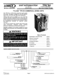
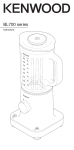
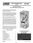
Service Literature
Corp. 0626−L5
Revised 06−2008
XP16
XP16 SERIES UNITS
The XP16 is a high efficiency residential split−system heat
pump unit, which features a scroll compressor and R−410A
refrigerant. XP16 units are available in 2, 3, 4 and 5 tons.
tons. XP16 units are rated for 230 volts only. Applications
where supply voltage is less requires a hard start kit. The
series is designed for use with an indoor unit with an expansion valve approved for R−410A. This manual is divided into
sections which discuss the major components, refrigerant
system, charging procedure, maintenance and operation
sequence.
Information contained in this manual is intended for use by
qualified service technicians only. All specifications are
subject to change.
IMPORTANT
Operating pressures of this R−410A unit are higher
than pressures in R−22 units. Always use service
equipment rated for R−410A.
WARNING
Warranty will be voided if covered equipment is removed from original installation site. Warranty will
not cover damage or defect resulting from:
Flood, wind, lightning, or installation and operation in a corrosive atmosphere (chlorine, fluorine,
salt, recycled waste water, urine, fertilizers, or other damaging chemicals).
TABLE OF CONTENTS
WARNING
Improper installation, adjustment, alteration, service
or maintenance can cause property damage, personal injury or loss of life. Installation and service must
be performed by a qualified installer or service
agency.
Specifications / Electrical . . . . . . . . . . . . . Page 2
I Unit Information . . . . . . . . . . . . . . . . . . . . Page 3
II Unit Components . . . . . . . . . . . . . . . . . . Page 4
III Refrigerant System . . . . . . . . . . . . . . . . Page 16
WARNING
IV Charging . . . . . . . . . . . . . . . . . . . . . . . . . Page 18
Electric shock hazard. Can cause injury
or death. Before attempting to perform
any service or maintenance, turn the
electrical power to unit OFF at disconnect switch(es). Unit may have multiple
power supplies.
Page 1
V Service and Recovery . . . . . . . . . . . . . . Page 21
VI Maintenance . . . . . . . . . . . . . . . . . . . . . . Page 22
VII Wiring Diagram . . . . . . . . . . . . . . . . . . . Page 23
©2006 Lennox Industries Inc.
SPECIFICATIONS
Model No.
Nominal Tonnage
Liquid line (o.d.) − in.
Connections
(
(sweat)
t)
Vapor line (o.d.) − in.
1 R−410A charge furnished
Refrigerant
Net face area − sq. ft. Outer coil
Outdoor
C il
Coil
Inner coil
Tube diameter − in.
No. of rows
Fins per inch
Diameter − in.
Outdoor
F
Fan
No. of blades
Motor hp
Cfm
Rpm
Watts
Shipping Data − lbs. 1 pkg.
General
D t
Data
XP16−024
2
3/8
3/4
9 lbs. 9 oz.
13.22
12.65
5/16
2
22
18
3
1/10
2215
1040
145
219
XP16−036
3
3/8
7/8
12 lbs. 8 oz.
18.67
18.0
5/16
2
22
22
4
1/6
3150
844
215
265
XP16−048
4
3/8
7/8
15 lbs. 7 oz.
24.5
23.64
5/16
2
22
22
4
1/4
3980
836
305
309
XP16−060
5
3/8
1−1/8
13 lbs. 8 oz.
24.93
24.14
5/16
2
22
26
3
1/3
4380
850
280
345
4 208/230V−1ph
4 208/230V−1ph
4 208/230V−1ph
4 208/230V−1ph
20
14.0
10.25
52
0.98
1.1
2
35
22.0
16.67
82
0.99
1.1
2.1
45
28.2
21.15
96
0.99
1.7
3.1
60
33.9
25.87
118
0.99
1.8
2.9
ELECTRICAL DATA
Line voltage data − 60hz
2 Maximum overcurrent protection (amps)
3 Minimum circuit ampacity
Rated load amps
Compressor
p
Locked rotor amps
Power factor
Full load amps
Outdoor Coil
F Motor
Fan
M t
Locked rotor amps
OPTIONAL ACCESSORIES − must be ordered extra
Compressor
p
Hard Start Kit − Required
q
i applications
in
li ti
with
ith lless th
than 230V
10J42
81J69
45F08
93G35
50A93
40K58
68M04
76F53
56A87
Compressor Low Ambient Cut−Off
3/8 in. tubing
Freezestat
5/8 in. tubing
Indoor Blower Relay
Low Ambient Kit
Monitor Kit − Service Light
Thermostat
Outdoor
Thermostat
Mounting Box
31461
Kit
SignatureStatt Home Comfort Control
81M28
L15−41−20
L15−41−40
Refrigerant
L15−41−30
L15−41−50
Line Sets
L15−65−30
Time Delay Relay
L15−65−40
L15−65−50
Field Fabricate
58M81
NOTE − Extremes of operating range are plus 10% and minus 5% of line voltage.
1
Refrigerant charge sufficient for 15 ft. length of refrigerant lines.
2
HACR type breaker or fuse.
3
Refer to National or Canadian Electrical Code manual to determine wire, fuse and disconnect size requirements.
4
Hard start kit is required in applications where the supply voltage is less than 230V.
Page 2
I − UNIT INFORMATION
All major components (indoor blower and coil) must be
matched according to Lennox recommendations for the
compressor to be covered under warranty. Refer to the Engineering Handbook for approved system matchups. A
misapplied system will cause erratic operation and can result in early compressor failure.
ELECTROSTATIC DISCHARGE (ESD)
Precautions and Procedures
Slightly rotate and guide the lip of top tab inward (figure 1,
Details A and C); then upward into the top slot of the
hinge corner post.
Rotate panel to vertical to fully engage all tabs.
Holding the panel’s hinged side firmly in place, close the
right−hand side of the panel, aligning the screw holes.
When panel is correctly positioned and aligned, insert the
screws and tighten.
Removing/Installing Louvered Panels
IMPORTANT! Do not allow panels to hang on unit by top tab. Tab
is for alignment and not designed to support weight of panel.
CAUTION
Panel shown slightly rotated to allow top tab to exit (or enter) top
slot for removing (or installing) panel.
Electrostatic discharge can affect electronic
components. Take precautions during unit installation and service to protect the unit’s electronic
controls. Precautions will help to avoid control
exposure to electrostatic discharge by putting
the unit, the control and the technician at the
same electrostatic potential. Neutralize electrostatic charge by touching hand and all tools on an
unpainted unit surface before performing any
service procedure.
SCREW
HOLES
LIP
Detail
A
Detail
B
CAUTION
To prevent personal injury, or damage to panels, unit
or structure, be sure to observe the following:
While installing or servicing this unit, carefully stow
all removed panels out of the way, so that the panels
will not cause injury to personnel, nor cause damage
to objects or structures nearby, nor will the panels be
subjected to damage (e.g., being bent or scratched).
While handling or stowing the panels, consider any
weather conditions, especially windy conditions,
that may cause panels to be blown around and battered.
Remove the louvered panels as follows:
1. Remove 2 screws, allowing the panel to swing open
slightly (see figure 1).
2. Hold the panel firmly throughout this procedure.
Rotate bottom corner of panel away from hinge corner
post until lower 3 tabs clear the slots (see figure 1, Detail B).
3. Move panel down until lip of upper tab clears the top slot
in corner post (see figure 1, Detail A).
Position and Install PanelPosition the panel almost
parallel with the unit (figure 1, Detail D) with the screw side"
as close to the unit as possible. Then, in a continuous motion:
Page 3
ROTATE IN THIS DIRECTION;
THEN DOWN TO REMOVE PANEL
Detail C
MAINTAIN MINIMUM PANEL ANGLE (AS CLOSE TO PARALLEL WITH THE UNIT
AS POSSIBLE) WHILE INSTALLING PANEL.
HOLD DOOR FIRMLY TO THE HINGED
ANGLE MAY BE TOO
SIDE TO MAINTAIN
EXTREME
FULLY−ENGAGED TABS
PREFERRED ANGLE
FOR INSTALLATION
Detail D
FIGURE 1
II − UNIT COMPONENTS
24V THERMOSTAT TERMINAL STRIP
Unit components are illustrated in figure 2.
XP16 UNIT COMPONENTS
OUTDOOR FAN
COMPRESSOR
Y1
O
Y2
R
L
C W1
FIGURE 4
CONTROL
BOX
1 − Compressor Contactor K1
REVERSING
VALVE
EXPANSION
VALVE
HIGH
PRESSURE
SWITCH
FILTER
DRIER
The compressor is energized by a contactor located in the
control box. See figure 3. Single−pole contactors are used
in all XP16 series units. K1 is energized through the control board by the indoor thermostat terminal Y1 (24V) when
thermostat demand is present.
DANGER
LOW PRESSURE
SWITCH
Electric Shock Hazard.
May cause injury or death.
Line voltage is present at all components when unit is not in operation on
units with single pole contactors.
Disconnect all remote electrical power
supplies before opening unit panel.
Unit may have multiple power supplies.
VAPOR LINE
SERVICE
LIQUID LINE
VALVE
SERVICE
VALVE
FIGURE 2
A − Control Box (Figure 3)
XP16 units are not equipped with a 24V transformer. All 24
VAC controls are powered by the indoor unit. Refer to wiring diagram.
UNIT CONTROL BOX
DUAL CAPACITOR
(C12)
COMPRESSOR
CONTACTOR
(K1)
DEFROST
CONTROL
(A108)
GROUNDING
LUG
FIGURE 3
Electrical openings are provided under the control box cover. Field thermostat wiring is made to a 24V terminal strip
located on the defrost control board located in the control
box. See figure 4.
2 − Dual Capacitor C12
The compressor and fan in XP16 series units use permanent
split capacitor motors. The capacitor is located inside the unit
control box (see figure 3). A single dual" capacitor (C12) is
used for both the fan motor and the compressor (see unit wiring diagram). The fan side and the compressor side of the capacitor have different MFD ratings. See side of capacitor for
ratings.
3 − Start Kit (option)
The start kit consists of a potential relay K31 and start capacitor C7. The potential relay controls the operation of the
starting circuit. The relay is normally closed when contactor
K1 is de−energized. When K1 is energized, the compressor
immediately begins start up. K31 remains closed during
compressor start up and and start capacitor C7 remains in
the circuit. When compressor reaches approximately 75%
of its speed, K31 is energized. When K31 energizes, the
contacts open and start capacitor C7 is taken out of the circuit.
Page 4
4 − Defrost Control
The demand defrost controller measures differential temperatures to detect when the system is performing poorly
because of ice build−up on the outdoor coil. The controller
self−calibrates" when the defrost system starts and after
each system defrost cycle. The defrost control board components are shown in figure 5.
Defrost Control Board
Defrost Board Pressure Switch Settings
Note − Component Locations Vary by Board Manufacturer.
TEST PINS
High Pressure (auto reset) − trip at 590 psig; reset at 418
psig.
Low Pressure (auto reset) − trip at 25 psig; reset at 40 psig.
LOW
AMBIENT
THERMOSTAT
PINS
DEFROST
TERMINATION
PIN SETTINGS
SENSOR PLUG IN
(COIL, AMBIENT,
& DISCHARGESENSORS)
during the defrost cycle and 90 seconds after the termination of defrost
when the average ambient sensor temperature is below
15° F (−9°C)
for 90 seconds following the start up of the compressor
during "test" mode
High Pressure Switch (HI−PS)When the high pressure
switch trips, the defrost board will cycle off the compressor,
and the strike counter in the board will count one strike.
5−Strike Lockout Feature
The internal control logic of the board counts the pressure
switch trips only while the Y1 (Input) line is active. If a pressure switch opens and closes four times during a Y1 (Input),
the control logic will reset the pressure switch trip counter to
zero at the end of the Y1 (Input). If the pressure switch
opens for a fifth time during the current Y1 (Input), the control will enter a lockout condition.
The 5−strike pressure switch lockout condition can be reset
by cycling OFF the 24−volt power to the control board or by
shorting the TEST pins between 1 and 2 seconds. All timer
functions (run times) will also be reset.
If a pressure switch opens while the Y1 Out line is engaged,
a 5−minute short cycle will occur after the switch closes.
DIAGNOSTIC
LEDS
DELAY
PINS
REVERSING
VALVE
24V TERMINAL
STRIP
CONNECTIONS
PRESSURE
SWITCH
CIRCUIT
CONNECTIONS
Defrost System Sensors
FIGURE 5
The control monitors ambient temperature, outdoor coil
temperature, and total run time to determine when a defrost cycle is required. The coil temperature probe is designed with a spring clip to allow mounting to the outside
coil tubing. The location of the coil sensor is important for
proper defrost operation.
NOTE − The demand defrost board accurately measures
the performance of the system as frost accumulates on the
outdoor coil. This typically will translate into longer running
time between defrost cycles as more frost accumulates on
the outdoor coil before the board initiates defrost cycles.
Diagnostic LEDs
The state (Off, On, Flashing) of two LEDs on the defrost
board (DS1 [Red] and DS2 [Green]) indicate diagnostics
conditions that are described in table 2.
Defrost Board Pressure Switch Connections
The unit’s automatic reset pressure switches (LO PS − S87
and HI PS − S4) are factory−wired into the defrost board on
the LO−PS and HI−PS terminals, respectively.
Low Pressure Switch (LO−PS)When the low pressure
switch trips, the defrost board will cycle off the compressor,
and the strike counter in the board will count one strike. The
low pressure switch is ignored under the following conditions:
Page 5
Sensors connect to the defrost board through a field-replaceable harness assembly that plugs into the board.
Through the sensors, the board detects outdoor ambient,
coil, and discharge temperature fault conditions. As the detected temperature changes, the resistance across the
sensor changes. Sensor resistance values can be checked
by ohming across pins shown in table 1. The graph in figure
6 shows sensor temperature to resistance range.
NOTE − When checking the ohms across a sensor, be
aware that a sensor showing a resistance value that is not
within the range shown in table 1, may be performing as designed. However, if a shorted or open circuit is detected,
then the sensor may be faulty and the sensor harness will
need to be replaced.
TABLE 1
Sensor Temperature / Resistance Range
Temperature
Range °F (°C)
Resistance values
range (ohms)
Pins/Wire
Color
Outdoor
−35 (−37) to 120
(48)
280,000 to 3750
3&4
(Black)
Coil
−35 (−37) to 120
(48)
280,000 to 3750
5&6
(Brown)
Discharge (if
applicable)
24 (−4) to 350
(176)
41,000 to 103
1&2
(Yellow)
Sensor
Note: Sensor resistance increases as sensed temperature decreases.
Ambient and Coil Sensor
90
TEMPERATURE (ºF)
80
Discharge Sensor
300
5750
280
7450
260
9275
70
11775
TEMPERATURE (ºF)
100
15425
60
19975
50
26200
40
34375
30
46275
20
62700
10
240
220
200
180
160
200
225
250
275
325
375
425
500
600
700
825
1000
1175
1400
1700
2025
2500
140
3000
3750
120
85300
0
4650
5825
100
10000
30000
50000
RESISTANCE (OHMS)
70000
90000
1000
2000
3000
4000
RESISTANCE (OHMS)
5000
6000
FIGURE 6
Sensor Locations
DETAIL B"
XP16−024
COIL SENSOR
7 tubes up from
bottom (7−1/2")
XP16−036
DEFROST BOARD
DEFROST SENSOR
HARNESS
COIL SENSOR
17 tubes up
from bottom
(17−1/2")
XP16−060
DETAIL A"
COIL SENSOR
12 tubes up from
bottom (11−1/2")
AMBIENT SENSOR
XP16−048
DISCHARGE LINE SENSOR
IN ONE OF TWO LOCATIONS
DETAIL C"
COIL SENSOR −
APPLY GREASE
BETWEEN RETURN
BEND AND SENSOR
FIGURE 7
Page 6
COIL SENSOR
13 tubes up from
bottom (12−1/2")
CLIP COIL TEMPERATURE SENSOR FROM THE
DEFROST BOARD ON THE RETURN BEND
SHOWN.
Ambient SensorThe ambient sensor (shown in detail A,
figure 7) considers outdoor temperatures below −35°F
(−37°C) or above 120°F (48°C) as a problem. If the ambient
sensor is detected as being open, shorted or out of the temperature range of the sensor, the board will not perform demand defrost operation. The board will revert to time/temperature defrost operation and will display the appropriate
fault code. Heating and cooling operation will be allowed in
this fault condition.
Coil SensorThe coil temperature sensor (shown in detail
B, figure 7) considers outdoor temperatures below −35°F
(−37°C) or above 120°F (48°C) as a problem. If the coil temperature sensor is detected as being open, shorted or out of
the temperature range of the sensor, the board will not perform demand or time/temperature defrost operation and
will display the appropriate fault code. Heating and cooling
operation will be allowed in this fault condition.
Discharge Line SensorIf the discharge line temperature (shown in figure 7) exceeds a temperature of 285°F
(140°C) during compressor operation, the board will de−energize the compressor contactor output (and the defrost
output, if active). The compressor will remain off until the
discharge temperature has dropped below 225°F (107°C)
and the 5-minute anti−short cycle delay has been satisfied.
This sensor has two fault and lockout codes:
4. If the board recognizes five high discharge line temperature faults during a single (Y1) compressor demand,
it reverts to a lockout mode and displays the appropriate code. This code detects shorted sensor or high discharge temperatures. (Code on board is Discharge
Line Temperature Fault and Lockout").
5. If the board recognizes five temperature sensor range
faults during a single (Y1) compressor demand, it reverts to a lockout mode and displays the appropriate
code. The board detects open sensor or out-of-temperature sensor range. This fault is detected by allowing
the unit to run for 90 seconds before checking sensor
resistance. If the sensor resistance is not within range
after 90 seconds, the board will count one fault. After
5 faults, the board will lockout. (Code on board is Discharge Sensor Fault and Lockout").
Page 7
The discharge line sensor, which covers a range of 150°F
(65°C) to 350°F (176°C), is designed to mount on a ½" refrigerant discharge line.
NOTE − Within a single room thermostat demand, if
5−strikes occur, the board will lockout the unit. Defrost
board 24 volt power R" must be cycled OFF" or the TEST"
pins on board must be shorted between 1 to 2 seconds to
reset the board.
Second−Stage OperationIf the board receives a call for
second−stage compressor operation Y2" in heating or
cooling mode and the first-stage compressor output is active, the second-stage compressor solenoid output will be
energized.
If first-stage compressor output is active in heating mode
and the outdoor ambient temperature is below the selected
compressor lock−in temperature, the second-stage compressor solenoid output will be energized without the Y2"
room thermostat input. If the jumper is not connected to one
of the temperature selection pins on P3 (40, 45, 50, 55°F),
the default lock−in temperature of 40°F (4.5°C) will be used.
The board de−energizes the second-stage compressor solenoid output immediately when the Y2" signal is removed
or the outdoor ambient temperature is 5°F above the selected compressor lock−in temperature, or the first-stage
compressor output is de−energized for any reason.
Defrost Temperature Termination Shunt (Jumper)
PinsThe defrost board selections are: 50, 70, 90, and
100°F (10, 21, 32 and 38°C). The shunt termination pin is
factory set at 50°F (10°C). If the temperature shunt is not
installed, the default termination temperature is 90°F
(32°C).
Delay Mode
The defrost board has a field−selectable function to reduce
occasional sounds that may occur while the unit is cycling in
and out of the defrost mode. When a jumper is installed on
the DELAY pins, the compressor will be cycled off for 30
seconds going in and out of the defrost mode. Units are
shipped with jumper installed on DELAY pins.
NOTE − The 30 second off cycle is NOT functional when
jumpering the TEST pins.
Operational Description
The defrost control board has three basic operational
modes: normal, calibration, and defrost.
Normal ModeThe demand defrost board monitors the O
line, to determine the system operating mode (heat/cool),
outdoor ambient temperature, coil temperature (outdoor
coil) and compressor run time to determine when a defrost
cycle is required.
Calibration ModeThe board is considered uncalibrated
when power is applied to the board, after cool mode operation, or if the coil temperature exceeds the termination temperature when it is in heat mode.
Calibration of the board occurs after a defrost cycle to ensure that there is no ice on the coil. During calibration, the
temperature of both the coil and the ambient sensor are
measured to establish the temperature differential which is
required to allow a defrost cycle.
Defrost ModeThe following paragraphs provide a detailed description of the defrost system operation.
Detailed Defrost System Operation
Defrost CyclesThe demand defrost control board initiates a defrost cycle based on either frost detection or time.
Frost DetectionIf the compressor runs longer than 34
minutes and the actual difference between the clear
coil and frosted coil temperatures exceeds the maximum difference allowed by the control, a defrost cycle
will be initiated.
TimeIf 6 hours of heating mode compressor run time has
elapsed since the last defrost cycle while the coil temperature remains below 35°F (2°C), the demand defrost control will initiate a defrost cycle.
ActuationWhen the reversing valve is de−energized, the
Y1 circuit is energized, and the coil temperature is below
35°F (2°C), the board logs the compressor run time. If the
board is not calibrated, a defrost cycle will be initiated after
34 minutes of heating mode compressor run time. The control will attempt to self−calibrate after this (and all other) defrost cycle(s).
Calibration success depends on stable system temperatures during the 20−minute calibration period. If the board
fails to calibrate, another defrost cycle will be initiated after
45 minutes (90 minutes on −1 to −4 boards) of heating mode
compressor run time. Once the defrost board is calibrated,
it initiates a demand defrost cycle when the difference between the clear coil and frosted coil temperatures exceeds
the maximum difference allowed by the control OR after 6
hours of heating mode compressor run time has been
logged since the last defrost cycle.
NOTE − If ambient or coil fault is detected, the board will not
execute the TEST" mode.
TerminationThe defrost cycle ends when the coil temperature exceeds the termination temperature or after 14
minutes of defrost operation. If the defrost is terminated by
the 14−minute timer, another defrost cycle will be initiated
after 34 minutes of run time.
Test ModeWhen Y1 is energized and 24V power is being
applied to the board, a test cycle can be initiated by placing
the termination temperature jumper across the Test" pins
for 2 to 5 seconds. If the jumper remains across the Test"
pins longer than 5 seconds, the control will ignore the test
pins and revert to normal operation. The jumper will initiate
one cycle per test.
Enter the TEST" mode by placing a shunt (jumper) across
the TEST" pins on the board after power−up. (The TEST"
pins are ignored and the test function is locked out if the
shunt is applied on the TEST" pins before power−up).
Board timings are reduced, the low−pressure switch and
loss of charge detection fault is ignored and the board will
clear any active lockout condition.
Each test pin shorting will result in one test event. For
each TEST" the shunt (jumper) must be removed for at
least 1 second and reapplied. Refer to flow chart (figure 8)
for TEST" operation.
Note: The Y1 input must be active (ON) and the O" room
thermostat terminal into board must be inactive.
Defrost Board Diagnostics
See table 2 to determine defrost board operational conditions and to diagnose cause and solution to problems.
Page 8
Test Mode
Y1 Active (0" line inactive)
Short test pins for longer
than 1 second but less than
2.0 seconds
Clear any short cycle lockout
and 5 strike fault lockout
function, if applicable. No
other functions will be
executed and unit will
continue in the mode it was
operating.
Short test pins for more than 2.0 seconds
Clear any short cycle lockout and 5 strike
fault lockout function, if applicable.
If in COOLING Mode
No further test mode
operation will be
executed until the test
short is removed and
reapplied.
If in HEATING Mode
The controller will check for
ambient and coil faults (open or
shorted). If a fault exists, the
unit will remain in Heat Mode
and no further test mode
operation will be executed until
the test short is removed and re
applied. If no fault exists, the
unit will go into Defrost mode.
Test pin short REMAINS in place for more than 5 seconds
The unit will return to Heat mode uncalibrated with defrost
timer set for 34 minutes. No further test mode operation will
be executed until the test short is removed and re applied.
FIGURE 8
Page 9
If in DEFROST Mode
The unit will terminate
defrost and enter Heat
Mode uncalibrated with
defrost timer set for 34
minute test. No further
test mode operation will
be executed until the test
short is removed and
reapplied.
Test pins short REMOVED before a
maximum of 5 seconds
The unit will remain in Defrost mode
until termination on time or temperature
TABLE 2
Defrost Control Board Diagnostic LEDs
DS2
DS1
Green Red
Condition/Code
Possible Cause(s)
Solution
OFF
Power problem
No power (24V) to board terminals R & C or board failure.
1 Check control transformer power (24V).
2 If power is available to board and LED(s)
OFF
do
not light, replace board.
Simultaneous
SLOW Flash
Normal operation
Unit operating normally or in
standby mode.
None required.
Alternating
SLOW Flash
5−minute anti−short cycle
delay
Initial power up, safety trip, end of
room thermostat demand.
None required (Jumper TEST pins to override)
Simultaneous
FAST Flash
Ambient Sensor Problem
Sensor being detected open or shorted or out of temperature range. Board will revert to time/temperature defrost operation. (System will still heat or cool).
Alternating
FAST Flash
Coil Sensor Problem
Sensor being detected open or shorted or out of temperature range. Board will not
perform demand or time/temperature defrost operation. (System will still heat or
cool).
ON
Circuit Board Failure
Indicates that board has internal component failure. Cycle 24 volt power to board. If
code does not clear, replace board.
ON
FAULT & LOCKOUT CODES (Each fault adds 1 strike to that code’s counter; 5 strikes per code = LOCKOUT)
OFF
SLOW
Flash
Low Pressure Fault
OFF
ON
Low Pressure LOCKOUT
SLOW
Flash
OFF
High Pressure Fault
ON
OFF
High Pressure LOCKOUT
SLOW
Flash
ON
Discharge Line Temperature Fault
FAST
Flash
ON
Discharge Line Temperature LOCKOUT
OFF
Fast
Flash
Discharge Sensor Fault
Fast
Flash
OFF
Discharge Sensor
LOCKOUT
1 Restricted
air flow over indoor
or outdoor coil.
2 Improper
p p refrigerant
g
g in
charge
system.
t
3 Improper metering device
installed or incorrect operation
of metering device.
4 Incorrect or improper sensor
location or connection to sys
system.
1 Remove
any blockages or restrictions from
coils and/or fans. Check indoor and outdoor
p p current draws.
fan motor for proper
2 Check
charge
using
Ch k system
t
h
i approach
h & subb
cooling temperatures.
3 Check system operating pressures and
compare to unit charging charts.
4 Make sure all pressure switches and sensors
have secure connections to system to prevent
refrigerant leaks or errors in pressure and
temperature measurements.
This code detects shorted sensor or high discharge temperatures. If the discharge
line temperature exceeds a temperature of 285ºF (140ºC) during compressor operation the board will de−energize the compressor contactor output (and the defrost
eration,
output if active). The compressor will remain off until the discharge temperature has
dropped below 225ºF (107ºC).
The board detects open sensor or out of temperature sensor range. This fault is
detected by allowing the unit to run for 90 seconds before checking sensor resistance If the sensor resistance is not within range after 90 seconds
ance.
seconds, the board will
count one fault. After 5 faults, the board will lockout.
Page 10
B − Two−Stage Scroll Compressor (B1)
CROSS−SECTION OF SCROLLS
DISCHARGE
DISCHARGE
PRESSURE
TWO−STAGE MODULATED SCROLL
slider ring
STATIONARY
SCROLL
SUCTION
TIPS SEALED BY
DISCHARGE PRESSURE
solenoid actuator coil
FIGURE 9
The scroll compressor design is simple, efficient and requires few moving parts. A cutaway diagram of the scroll
compressor is shown in figure 1.The scrolls are located in
the top of the compressor can and the motor is located just
below. The oil level is immediately below the motor.
The scroll is a simple compression concept centered
around the unique spiral shape of the scroll and its inherent
properties. Figure 10 shows the basic scroll form. Two identical scrolls are mated together forming concentric spiral
shapes (figure 11). One scroll remains stationary, while the
other is allowed to orbit" (figure 12). Note that the orbiting
scroll does not rotate or turn but merely orbits" the stationary scroll.
SCROLL FORM
FIGURE 10
Page 11
ORBITING SCROLL
FIGURE 11
The counterclockwise orbiting scroll draws gas into the outer
crescent shaped gas pocket created by the two scrolls (figure 4 − 1). The centrifugal action of the orbiting scroll seals off
the flanks of the scrolls (figure 4 − 2). As the orbiting motion
continues, the gas is forced toward the center of the scroll
and the gas pocket becomes compressed (figure 4 −3).
When the compressed gas reaches the center, it is discharged vertically into a chamber and discharge port in the
top of the compressor (figure9). The discharge pressure
forcing down on the top scroll helps seal off the upper and
lower edges (tips) of the scrolls (figure 11). During a single
orbit, several pockets of gas are compressed simultaneously providing smooth continuous compression.
The scroll compressor is tolerant to the effects of liquid return. If liquid enters the scrolls, the orbiting scroll is allowed
to separate from the stationary scroll. The liquid is worked
toward the center of the scroll and is discharged.
Due to its efficiency, the scroll compressor is capable of
drawing a much deeper vacuum than reciprocating compressors. Deep vacuum operation can cause internal fusite
arcing resulting in damaged internal parts and will result in
compressor failure. This type of damage can be detected
and will result in denial of warranty claims. The scroll compressor can be used to pump down refrigerant as long as
the pressure is not reduced below 7 psig.
NOTE − During operation, the head of a scroll compressor
may be hot since it is in constant contact with discharge
gas.
The scroll compressors in all XP16 model units are designed for use with R410A refrigerant and operation at high
pressures. Compressors are shipped from the factory with
3MA (32MMMA) P.O.E. oil. See electrical section in this
manual for compressor specifications.
TWO−STAGE OPERATION
The two−stage scroll compressor operates like any standard scroll compressor with the exception the two−stage
compressor modulates between first stage (low capacity
approximately 67%) and second stage (high capacity).
Modulation occurs when gas is bypassed through bypass
ports (figure 13 bypass ports open) in the first suction pocket. This bypassing of gas allows the compressor to operate
on first stage (low capacity) if thermostat demand allows.
Indoor thermostat setting will determine first or second
stage operation. The compressor will operate on first−stage
until demand is satisfied or the indoor temperature reaches
the thermostat set point calling for second−stage.
Second−stage (high capacity) is achieved by blocking the
bypass ports (figure 13 bypass ports closed) with a slider
ring. The slider ring begins in the open position and is controlled by a 24VDC internal solenoid. On a Y2 call the internal solenoid closes the slider ring, blocking the bypass
ports and bringing the compressor to high capacity. Two−
stage modulation can occur during a single thermostat demand as the motor runs continuously while the compressor
modulates from first−stage to second− stage.
HOW A SCROLL WORKS
MOVEMENT OF ORBIT
SUCTION
SUCTION
INTERMEDIATE
PRESSURE
GAS
CRESCENT
SHAPED GAS
POCKET
ORBITING
SCROLL
SUCTION
POCKET
1
SUCTION
2
FLANKS
SEALED BY
STATIONARY SCROLL CENTRIFUGAL
FORCE
3
SUCTION
4
HIGH
PRESSURE
GAS
DISCHARGE
POCKET
FIGURE 12
TWO−STAGE MODULATION
Bypass Ports
Closed
High Capacity
FIGURE 13
Page 12
Bypass Ports
Open
Low Capacity
INTERNAL SOLENOID (L34)
Procedure
The internal unloader solenoid controls the two−stage operation of the compressor by shifting a slide ring mechanism to open two by−pass ports in the first compression
pocket of the scrolls in the compressor. The internal solenoid is activated by a 24 volt direct current solenoid coil.
The coil power requires 20VAC. The internal wires from the
solenoid in the compressor are routed to a 2 pin fusite connection on the side of the compressor shell. The external
electrical connection is made to the compressor with a
molded plug assembly. This plug contains a full wave rectifier that converts 24 volt AC into 24 volt DC power to power
the unloader solenoid. Refer to unit diagram for internal circuitry view of plug.
If it is suspect the unloader is not operating properly, check
the following
IMPORTANT
1. Turn main power "OFF" to outdoor unit.
2. Adjust room thermostat set point above (heating operation on heat pump) or below (cooling operation) the
room temperature 5ºF.
3. Remove control access panel. Install refrigeration
gauges on unit. Attach the amp meter to the common
(black wire) wire of the compressor harness. Attach
thermometer to discharge line as close as possible to
the compressor.
4. Turn toggle switch "OFF" and install switch in series
with Y2 wire from room thermostat.
5. Cycle main power "ON."
6. Allow pressures and temperatures to stabilize before
taking any measured reading (may take up to 10 minutes).
NOTE − Block outdoor coil to maintain a minimum of 375
psig during testing).
7. Record all of the readings for the Y1 demand on table
3.
This performance check is ONLY valid on systems
that have clean indoor and outdoor coils, proper airflow over coils, and correct system refrigerant
charge. All components in the system must be functioning proper to correctly perform compressor modulation operational check. (Accurate measurements
are critical to this test as indoor system loading and
outdoor ambient can affect variations between low
and high capacity readings).
STEP 1 Confirm low to high capacity compressor operation
Tools required
Refrigeration gauge set
Digital volt/amp meter
Electronic temperature thermometer
On-off toggle switch
Page 13
8. Close switch to energize Y2 demand.
9. Allow pressures and temperatures to stabilize before
taking any measured reading (this may take up to 10
minutes).
10. Record all of the readings of Y2 demand on table 3.
NOTE − On new installations or installations that have
shut down for an extended period of time, if the compressor does not cycle from low stage to high stage on the
first attempt, it may be necessary to recycle the compressor back down to low stage and back up to high stage a
few times in order to get the bypass seals to properly
seat
Compare Y1 readings with Y2 readings in table 3. Some
readings should be higher, lower or the same. If the readings follow what table 3 specifies, the compressor is operating and shifting to high capacity as designed. If the
readings do not follow what table 3 specifies, continue to
step 2 to determine if problem is with external solenoid
plug power.
TABLE 3
Compressor Operation
Unit Readings
Y1 −
1st-Stage
Expected Results
Y2 −
2nd-Stage
Compressor
Voltage
Amperage
Same
Higher
Condenser Fan motor
Amperage
Same or Higher
Temperature
Ambient
Outdoor Coil Discharge Air
Same
Higher in Cooling
Lower in Heating
Higher
Same
Lower in Cooling
Higher in Heating
Compressor Discharge Line
Indoor Return Air
Indoor Coil Discharge Air
Pressures
Suction (Vapor)
Liquid
Lower
Higher
STEP 2 Confirm DC voltage output on compressor
solenoid plug
rectifier plug leads
apply 24vac
A − Compressor solenoid plug WITH built in full wave−
rectifier (LSOM I) that converts 24 volt AC into 24 volt DC
power. See Table 1 for units equipped with the LSOM I.
compressor
fusite
terminals
1. Shut power off to outdoor unit.
solenoid
fusite
terminals
meter
compressor
2. Supply 24 volts AC control voltage to the wire ends of
the full wave rectifier plug. Listen for a click" as the solenoid is energized. See figure 14.
rectifier plug leads
apply 24vac
FIGURE 15
If the above checks verify that the solenoid plug is providing power to cycle into high capacity operation, continue to step 3 to determine if problem is with solenoid coil
in compressor
STEP 3 Confirm internal unloader solenoid has proper resistance
solenoid fusite
terminals
compressor
fusite
terminals
1. Shut all power off to unit (main and low voltage)
meter
compressor
FIGURE 14
3. Unplug the full wave rectifier plug from the fusite connection on the compressor.
4. Turn the low voltage power back onto the unit. Supply
24VAC to the wires of the full wave rectifier plug. Set
volt meter to DC volts and measure the DC voltage at
the female connector end of the full wave rectifier plug.
The DC voltage reading should be 1.5 to 3 volts lower
than the input voltage to the plug wire leads. (EX: Input
voltage is 24VAC output voltage is 22VDC).
See figure 15.
2. Unplug the molded plug from the compressor solenoid
2−pin fusite.
3. Using a volt meter set on the 200 ohm scale
Replace the Compressor under these conditions:
Bad Solenoid
a. Measure the resistance at the 2−pin fusite. The resistance should be 32 to 60 ohms depending on compressor
temperature. If no resist ancereplace compressor.
b. Measure the resistance from each fusite pin to ground.
There should not be continuity to ground. If solenoid coil
is grounded, replace compressor.
Good Solenoid
a. Seals not shifting, replace compressor
b. Slider ring not shifting, replace compressor.
Page 14
C − Outdoor Fan Motor
D − Reversing Valve L1 and Solenoid
All units use single−phase PSC fan motors which require a run
capacitor. In all units, the condenser fan is controlled by
the compressor contactor.
A refrigerant reversing valve with electromechanical solenoid is used to reverse refrigerant flow during unit operation. The reversing valve requires no maintenance. It
is not repairable. If the reversing valve has failed, it must
be replaced.
ELECTRICAL DATA tables in this manual show specifications for condenser fans used in XP16’s.
Access to the condenser fan motor on all units is gained
by removing the four screws securing the fan assembly.
See figure 16. The grill fan assembly can be removed
from the cabinet as one piece. See figure 17. The condenser fan motor is removed from the fan guard by removing the four nuts found on top of the grill. See figure
17 if condenser fan motor replacement is necessary.
DANGER
E − Crankcase Heater (HR1)
& Thermostat (S40)
The compressor in the unit is equipped with a 70 watt, belly
band type crankcase heater. HR1 prevents liquid from accumulating in the compressor. HR1 is controlled by a thermostat located on the liquid line. When liquid line temperature
drops below 50° F the thermostat closes energizing HR1.
The thermostat will open, de−energizing HR1 once liquid line
temperature reaches 70° F .
F − Drier
Make sure all power is disconnected before
beginning electrical service procedures.
A filter drier designed for all XP16 model units is factory
installed in the liquid line. The filter drier is designed to remove moisture and foreign matter, which can lead to compressor failure.
Remove
screws
Moisture and / or Acid Check
Because POE oils absorb moisture, the dryness of the
system must be verified any time the refrigerant system is exposed to open air. A compressor oil sample must
be taken to determine if excessive moisture has been
introduced to the oil. Table 4 lists kits available from Lennox
to check POE oils.
If oil sample taken from a system that has been exposed to
open air does not test in the dry color range, the filter drier
MUST be replace.
Remove
screws
IMPORTANT
FIGURE 16
Replacement filter drier MUST be approved for
R−410A refrigerant and POE application.
Foreign Matter Check
NUTS (4)
It is recommended that a liquid line filter drier be replaced
when the pressure drop across the filter drier is greater than
4 psig. To safeguard against moisture entering the system
follow the steps in section IV − sub section B − "Evacuating
the System" when replacing the drier.
ALIGN FAN HUB FLUSH WITH END OF SHAFT
FIGURE 17
TABLE 4
KIT
CONTENTS
TUBE SHELF LIFE
10N46 − Refrigerant Analysis
Checkmate−RT700
10N45 − Acid Test Tubes
Checkmate−RT750A (three pack)
2 − 3 years @ room temperature. 3+
years refrigerated
10N44 − Moisture Test Tubes
Checkmate − RT751 Tubes (three
pack)
6 − 12 months @ room temperature. 2
years refrigerated
74N40 − Easy Oil Test Tubes
Checkmate − RT752C Tubes (three
pack)
2 − 3 years @ room temperature. 3+
years refrigerated
74N39 − Acid Test Kit
Sporian One Shot − TA−1
Page 15
An auto-reset, single-pole/single-throw low pressure
switch is located in the suction line. This switch shuts off the
compressor when suction pressure drops below the factory
setting. The switch is closed during normal operating pressure conditions and is permanently adjusted to trip (open)
at 25 + 5 psi. The switch automatically resets when suction
line pressure rises above 40 + 5 psi. Under certain conditions the low pressure switch is ignored. See Pressure
Switch Circuit in the Defrost Control description.
G − High/Low Pressure Switch
IMPORTANT
Pressure switch settings for R−410A refrigerant
will be significantly higher than units with R−22.
An auto-reset, single-pole/single-throw high pressure switch
is located in the liquid line. This switch shuts off the compressor when liquid line pressure rises above the factory setting.
The switch is normally closed and is permanently adjusted to
trip (open) at 590 + 10 psi.
III − REFRIGERANT SYSTEM
Refer to figure 18 for refrigerant flow. The reversing
valve is energized during cooling demand and during
defrost.
XP16 COOLING CYCLE (SHOWING MANIFOLD GAUGE CONNECTIONS)
OUTDOOR UNIT
DISTRIBUTOR
COIL SENSOR
REVERSING VALVE
EXPANSION/CHECK
VALVE
LOW
PRESSURE
HIGH
PRESSURE
BIFLOW
FILTER / DRIER OUTDOOR
COIL
INTERNAL
COMPRESSOR
LIMIT
INDOOR UNIT
MUFFLER
GAUGE MANIFOLD
TO
R−410A
DRUM
LIQUID LINE
SERVICE
PORT
SUCTION
SERVICE
PORT
VAPOR
LINE
VALVE
COMPRESSOR
EXPANSION/CHECK
VALVE
NOTE − ARROWS INDICATE DIRECTION OF REFRIGERANT FLOW. REFRIGERANT WILL FLOW IN
OPPOSITE DIRECTION IN HEATING CYCLE
FIGURE 18
Page 16
INDOOR
COIL
A − Plumbing
To Close Service Valve:
Field refrigerant piping consists of liquid and vapor lines
from the outdoor unit (sweat connections). Use Lennox
L15 (sweat) series line sets as shown in table 1.
TABLE 1
1 − Remove the stem cap with an adjustable wrench.
2 − Use a service wrench with a hex−head extension to turn
the stem clockwise to seat the valve. Tighten the stem
firmly.
NOTE − Use a 3/16" hex head extension for 3/8" line
sizes or a 5/16" extension for large line sizes.
3 − Replace the stem cap. Tighten finger tight, then tighten
an additional 1/6 turn.
Unit
Liquid
Line
Suction
Line
L15 Line Sets
−024,
3/8 in.
(10 mm)
3/4 in.
(19 mm)
L15−65
15 ft. − 50 ft.
(4.6 m − 15 m)
7/8 in.
(22 mm)
L15−65
15 ft. − 50 ft.
(4.6 m − 15 m)
−036,
−048
−060
3/8 in.
(10 mm)
3/8 in.
(10 mm)
1−1/8 in.
(29 mm)
Service Valve
(Valve Closed)
stem cap
service
port
Field
Fabricated
insert hex
wrench here
to outdoor coil
B − Service Valves
service
port cap
IMPORTANT
Only use Allen wrenches of sufficient hardness
(50Rc − Rockwell Harness Scale min). Fully insert the wrench into the valve stem recess.
Service valve stems are factory torqued (from 9
ft lbs for small valves, to 25 ft lbs for large
valves) to prevent refrigerant loss during shipping and handling. Using an Allen wrench rated
at less than 50Rc risks rounding or breaking off
the wrench, or stripping the valve stem recess.
to indoor coil
Schrader valve open
to line set when valve is
closed (front seated)
(valve front seated)
insert hex
wrench here
Service valves (figures 19 and 20) and gauge ports are accessible from the outside of the unit. Use the service ports
for leak testing, evacuating, charging and checking charge.
Each valve is equipped with a service port which has a factory−installed Schrader valve. A service port cap protects
the Schrader valve from contamination and serves as the
primary leak seal.
To Access Schrader Port:
1 − Remove service port cap with an adjustable wrench.
2 − Connect gauge to the service port.
3 − When testing is complete, replace service port cap. Tighten finger tight, then an additional 1/6 turn.
To Open Service Valve:
1 − Remove the stem cap with an adjustable wrench.
2 − Use a service wrench with a hex−head extension to
back the stem out counterclockwise as far as it will go.
NOTE − Use a 3/16" hex head extension for 3/8" line
sizes or a 5/16" extension for large line sizes.
3 − Replace the stem cap. Tighten finger tight, then tighten
an additional 1/6 turn.
Page 17
Service Valve
(Valve Open)
stem cap
service
port
to outdoor coil
service port
cap
to indoor coil
Schrader
valve
FIGURE 19
Vapor Line Ball Valve – 4 & 5 Ton Only
Vapor line service valves function the same way as the other valves, the difference is in the construction. If a valve has
failed, you must replace it. A ball valve is illustrated in figure
20.
The ball valve is equipped with a service port with a factory−
installed Schrader valve. A service port cap protects the
Schrader valve from contamination and assures a leak−free
seal.
Ball Valve (Valve Open)
Use Adjustable Wrench
To open: rotate Stem Clockwise 90°.
To close: rotate Stem Counter-clockwise 90°.
stem cap
to outdoor coil
stem
ball
(shown open)
to indoor coil
service port
cap
service port
Schrader valve
FIGURE 20
IV − CHARGING
A − Leak Testing
After the line set has been connected to the indoor and outdoor units, check the line set connections and indoor unit
for leaks.
WARNING
Refrigerant can be harmful if it is inhaled. Refrigerant
must be used and recovered responsibly.
Failure to follow this warning may result in personal
injury or death.
WARNING
Fire, Explosion and Personal Safety
Hazard.
Failure to follow this warning could
result in damage, personal injury or
death.
Never use oxygen to pressurize or
purge refrigeration lines. Oxygen,
when exposed to a spark or open
flame, can cause damage by fire and
/ or an explosion, that can result in
personal injury or death.
WARNING
Danger of explosion!
When using a high pressure gas such
as dry nitrogen to pressurize a refrigerant or air conditioning system, use a
regulator that can control the pressure
down to 1 or 2 psig (6.9 to 13.8 kPa).
Using an Electronic Leak Detector or Halide
1 − Connect a cylinder of R−410A to the center port of the
manifold gauge set.
2 − With both manifold valves closed, open the valve on the
R−410A cylinder (vapor only).
3 − Open the high pressure side of the manifold to allow the
R−410A into the line set and indoor unit. Weigh in a
trace amount of R−410A. [A trace amount is a maximum
of 2 ounces (57 g) or 3 pounds (31 kPa) pressure.]
Close the valve on the R−410A cylinder and the valve
on the high pressure side of the manifold gauge set.
Disconnect the R−410A cylinder.
4 − Connect a cylinder of nitrogen with a pressure regulating valve to the center port of the manifold gauge set.
5 − Connect the manifold gauge set high pressure hose to
the vapor valve service port. (Normally, the high pressure hose is connected to the liquid line port; however,
connecting it to the vapor port better protects the manifold gauge set from high pressure damage.)
6 − Adjust the nitrogen pressure to 150 psig (1034 kPa).
Open the valve on the high side of the manifold gauge
set which will pressurize line set and indoor unit.
7 − After a few minutes, open a refrigerant port to ensure
the refrigerant you added is adequate to be detected.
(Amounts of refrigerant will vary with line lengths.)
Check all joints for leaks. Purge nitrogen and R−410A
mixture. Correct any leaks and recheck.
B − Evacuating the System
Evacuating the system of noncondensables is critical for
proper operation of the unit. Noncondensables are defined
as any gas that will not condense under temperatures and
pressures present during operation of an air conditioning
system. Noncondensables and water vapor combine with
refrigerant to produce substances that corrode copper piping and compressor parts.
NOTE − This evacuation process is adequate for a new
installation with clean and dry lines. If excessive moisture is present, the evacuation process may be required more than once.
IMPORTANT
Use a thermocouple or thermistor electronic vacuum
gauge that is calibrated in microns. Use an instrument
that reads from 50 microns to at least 10,000 microns.
1 − Connect manifold gauge set to the service valve ports :
low pressure gauge to vapor line service valve
high pressure gauge to liquid line service valve
2 − Connect micron gauge.
3 − Connect the vacuum pump (with vacuum gauge) to the
center port of the manifold gauge set.
4 − Open both manifold valves and start the vacuum
pump.
Page 18
5 − Evacuate the line set and indoor unit to an absolute
pressure of 23,000 microns (29.01 inches of mercury). During the early stages of evacuation, it is desirable
to close the manifold gauge valve at least once to determine if there is a rapid rise in absolute pressure. A
rapid rise in pressure indicates a relatively large leak. If
this occurs, repeat the leak testing procedure.
NOTE − The term absolute pressure means the total
actual pressure within a given volume or system,
above the absolute zero of pressure. Absolute pressure in a vacuum is equal to atmospheric pressure minus vacuum pressure.
6 − When the absolute pressure reaches 23,000 microns
(29.01 inches of mercury), close the manifold gauge
valves, turn off the vacuum pump and disconnect the
manifold gauge center port hose from vacuum pump.
Attach the manifold center port hose to a nitrogen cylinder with pressure regulator set to 150 psig (1034 kPa)
and purge the hose. Open the manifold gauge valves to
break the vacuum in the line set and indoor unit. Close
the manifold gauge valves.
CAUTION
Danger of Equipment Damage.
Avoid deep vacuum operation. Do not use compressors to evacuate a system.
Extremely low vacuums can cause internal arcing
and compressor failure.
Damage caused by deep vacuum operation will void
warranty.
7 − Shut off the nitrogen cylinder and remove the manifold
gauge hose from the cylinder. Open the manifold
gauge valves to release the nitrogen from the line set
and indoor unit.
8 − Reconnect the manifold gauge to the vacuum pump,
turn the pump on, and continue to evacuate the line set
and indoor unit until the absolute pressure does not rise
above 500 microns (29.9 inches of mercury) within a
20−minute period after shutting off the vacuum pump
and closing the manifold gauge valves.
9 − When the absolute pressure requirement above has
been met, disconnect the manifold hose from the vacuum pump and connect it to an upright cylinder of R−410A
refrigerant. Open the manifold gauge valves to break
the vacuum from 1 to 2 psig positive pressure in the line
set and indoor unit. Close manifold gauge valves and
shut off the R−410A cylinder and remove the manifold
gauge set.
Page 19
C − Charging
Charge Using the Weigh-in MethodOutdoor
Temperature < 65ºF (18ºC)
If the system is void of refrigerant, or if the outdoor ambient
temperature is cool, first, locate and repair any leaks and
then weigh in the refrigerant charge into the unit.
1. Recover the refrigerant from the unit.
2. Conduct leak check; evacuate as previously outlined.
3. Weigh in the unit nameplate charge. If weighing facilities are not available or if charging the unit during warm
weather, use one of the following procedures.
Charge Using the Subcooling MethodOutdoor
Temperature < 65ºF (18ºC)
When the outdoor ambient temperature is below 65°F
(18°C), use the subcooling method to charge the unit. If
necessary, restrict the air flow through the outdoor coil to
achieve pressures in the 325−375 psig (2240−2585 kPa)
range. These higher pressures are necessary for checking
the charge. Block equal sections of air intake panels and
move obstructions sideways until the liquid pressure is in
the 325−375 psig (2240−2585 kPa) range. See figure 21.
Blocking Outdoor Coil
BLOCK OUTDOOR COIL ONE
SIDE AT A TIME WITH
CARDBOARD OR PLASTIC
SHEET UNTIL PROPER TESTING
PRESSURES ARE REACHED.
CARDBOARD OR PLASTIC
SHEET
FIGURE 21
1. With the manifold gauge hose still on the liquid service
port and the unit operating stably, use a digital thermometer to check the liquid line temperature and record in table 3.
2. At the same time, record the liquid line pressure reading.
3. Use a temperature/pressure chart for R−410A (table 2)
to determine the saturation temperature for the liquid
line pressure reading; record in table 3.
TABLE 2
Charge Using the Approach MethodOutdoor
R−410A Temperature (°F) − Pressure (Psig)
°F
Psig
°F
Psig
°F
Psig
°F
Psig
32
33
100.8
102.9
63
64
178.5
181.6
94
95
290.8
295.1
125
126
445.9
451.8
34
105.0
65
184.3
96
299.4
127
457.6
35
107.1
66
187.7
97
303.8
128
463.5
36
109.2
67
190.9
98
308.2
129
469.5
37
111.4
68
194.1
99
312.7
130
475.6
38
113.6
69
197.3
100
317.2
131
481.6
39
115.8
70
200.6
101
321.8
132
487.8
40
118.0
71
203.9
102
326.4
133
494.0
41
120.3
72
207.2
103
331.0
134
500.2
42
122.6
73
210.6
104
335.7
135
506.5
43
125.0
74
214.0
105
340.5
136
512.9
44
127.3
75
217.4
106
345.3
137
519.3
45
129.7
76
220.9
107
350.1
138
525.8
46
132.2
77
224.4
108
355.0
139
532.4
47
134.6
78
228.0
109
360.0
140
539.0
48
137.1
79
231.6
110
365.0
141
545.6
49
139.6
80
235.3
111
370.0
142
552.3
50
142.2
81
239.0
112
375.1
143
559.1
51
144.8
82
242.7
113
380.2
144
565.9
52
147.4
83
246.5
114
385.4
145
572.8
53
150.1
84
250.3
115
390.7
146
579.8
54
152.8
85
254.1
116
396.0
147
586.8
55
155.5
86
258.0
117
401.3
148
593.8
56
158.2
87
262.0
118
406.7
149
601.0
57
161.0
88
266.0
119
412.2
150
608.1
58
163.9
89
270.0
120
417.7
151
615.4
59
166.7
90
274.1
121
423.2
152
622.7
60
169.6
91
278.2
122
428.8
153
630.1
61
172.6
92
282.3
123
434.5
154
637.5
62
175.4
93
286.5
124
440.2
155
645.0
Temperature > 65ºF (18ºC)
The following procedure is intended as a general guide and
is for use on expansion valve systems only. For best results,
indoor temperature should be 70°F (21°C) to 80°F (26°C).
Monitor system pressures while charging.
1. Check the outdoor ambient temperature using a digital
thermometer and record in table 4.
2. Attach high pressure gauge set and operate unit for
several minutes to allow system pressures to stabilize.
3. Compare stabilized pressures with those provided in
tables 5 and 6, Normal Operating Pressures." Minor
variations in these pressures may be expected due to
differences in installations. Significant differences
could mean that the system is not properly charged or
that a problem exists with some component in the system. Pressures higher than those listed indicate that
the system is overcharged. Pressures lower than those
listed indicate that the system is undercharged. Continue to check adjusted charge using approach values.
4. Use the same digital thermometer used to check outdoor ambient temperature to check liquid line temperature and record in table 4. Verify the unit charge using
the approach method. The difference between the ambient and liquid temperatures should match values given in table 4. Add refrigerant to lower the approach temperature and remove it to increase the approach temperature. Loss of charge results in low capacity and efficiency.
4. Subtract the liquid line temperature from the saturation
temperature (according to the chart) to determine the
subcooling value.
5. Compare the subcooling value with those in table 3. If
subcooling value is greater than shown, recover some
refrigerant; if less, add some refrigerant.
TABLE 3
5. If the values do not agree with those in table 4, add refrigerant to lower the approach temperature or recover
refrigerant from the system to increase the approach
temperature.
Subcooling Values for Charging
Second Stage (High-Capacity)
Approach Values for Charging
Second-Stage (High-Capacity)
=
Saturation Temperature
Liquid Line Temperature
Subcooling Value
XP16 −024
°F (°C)*
TABLE 4
8 (4.4)
*F: +/−1.0°; C: +/−0.5°
−036
7 (3.9)
−048
9 (5)
=
XP16
−060
8 (4.4)
°F (°C)*
Liquid Line Temperature
Outdoor Temperature
Approach Temperature
−018
8 (4.4)
*F: +/−1.0°; C: +/−0.5°
Page 20
−036
9 (5)
−048
8 (4.4)
−060
8 (4.4)
V − SERVICE AND RECOVERY
IMPORTANT
Use tables 5 and 6 as a general guide when performing maintenance checks. This is not a procedure for
charging the unit (Refer to Charging/Checking
Charge section). Minor variations in these pressures
may be expected due to differences in installations.
Significant differences could mean that the system is
not properly charged or that a problem exists with
some component in the system.
WARNING
Polyol ester (POE) oils used with R−410A refrigerant absorb moisture very quickly. It is very important that the refrigerant system be kept closed as
much as possible. DO NOT remove line set caps or
service valve stub caps until you are ready to make
connections.
TABLE 5
IMPORTANT
Normal Operating Pressures − Cooling1
XP16
°F (°C)2
−024
Liq Vap
−036
Liq Vap
−048
Liq Vap
−060
Liq Vap
First Stage (Low Capacity) Pressure3
65 (18.3)
232
264
146
148
225
261
144
147
235
268
144
145
225
264
138
141
105 (40.6)
307
353
403
149
151
153
302
349
397
149
151
153
310
356
407
147
148
150
305
352
405
142
146
148
115 (46.1)
460
155
461
157
466
152
459
150
75 (23.9)
85 (29.4)
95 (35.0)
Second Stage (High Capacity) Pressure3
65 (18.3)
240
279
322
143
145
147
239
278
322
139
141
143
244
283
326
140
141
144
241
280
324
134
136
137
105 (40.6)
371
423
149
151
367
426
146
148
374
427
147
148
373
425
138
142
115 (46.1)
485
154
489
151
491
151
486
146
75 (23.9)
85 (29.4)
95 (35.0)
1 These are most−popular−match−up pressures. Indoor match up,
indoor air quality, and indoor load cause pressures to vary.
2 Temperature of the air entering the outdoor coil.
3 Liquid ±10 & Vapor ±5 psig.
TABLE 6
Normal Operating Pressures − Heating1
XP16
°F (°C)2
−024
Liq Vap
−036
Liq Vap
−048
Liq Vap
−060
Liq Vap
First Stage (Low Capacity) Pressure3
40 (4.4)
337
93
328
98
369
75
351
63
50 (10)
322
117
333
118
366
114
335
92
Second Stage (High Capacity) Pressure3
20 (−7.0)
40 (4.4)
279
288
302
62
76
93
296
309
322
62
75
92
311
334
354
58
72
89
308
323
318
59
70
69
50 (10)
306
112
336
113
381
108
329
82
30 (−1.0)
1 These are most−popular−match−up pressures. Indoor match up,
indoor air quality, and indoor load cause pressures to vary.
2 Temperature of the air entering the outdoor coil.
3 Liquid ±10 & Vapor ±5 psig.
Page 21
Use recovery machine rated for R410 refrigerant.
If the XP16 system must be opened for any kind of service,
such as compressor or drier replacement, you must take
extra precautions to prevent moisture from entering the
system. The following steps will help to minimize the
amount of moisture that enters the system during recovery
of R−410A.
1 − Use a regulator−equipped nitrogen cylinder to break
the system vacuum. Do not exceed 5 psi. The dry nitrogen will fill the system, and will help purge any moisture.
2 − Remove the faulty component and quickly seal the system (using tape or some other means) to prevent additional moisture from entering the system.
3 − Do not remove the tape until you are ready to install
new component. Quickly install the replacement component.
4 − Evacuate the system to remove any moisture and other
non−condensables.
The XP16 system MUST be checked for moisture any
time the sealed system is opened.
Any moisture not absorbed by the polyol ester oil can be removed by triple evacuation. Moisture that has been absorbed by the compressor oil can be removed by replacing
the drier.
IMPORTANT
Evacuation of system only will not remove moisture from oil. Drier must be replaced to eliminate
moisture from POE oil.
VI − MAINTENANCE
B − Indoor Coil
In order to maintain the warranty on this equipment, the
XP16 system must be serviced annually and a record of
service maintained. The following should be checked between annual maintenance:
1 − Clean coil, if necessary.
A − Outdoor Unit
3 − Check the condensate line and clean it if necessary.
1 − Clean and inspect the outdoor coil. The coil may be
flushed with a water hose. Ensure the power is turned
off before you clean the coil.
2 − Condenser fan motor is prelubricated and sealed. No
further lubrication is needed.
3 − Visually inspect connecting lines and coils for evidence
of oil leaks.
4 − Check wiring for loose connections.
5 − Check for correct voltage at unit (unit operating).
6 − Check amp−draw condenser fan motor.
Unit nameplate _________ Actual ____________ .
NOTE − If owner complains of insufficient cooling, the unit
should be gauged and refrigerant charge checked. Refer
to section on refrigerant charging in this instruction.
1 − Clean and inspect condenser coil. (Coil may be flushed
with a water hose after disconnecting power).
2 − Visually inspect all connecting lines, joints and coils for
evidence of oil leaks.
C − Indoor Unit
2 − Check connecting lines and coils for evidence of oil
leaks.
1 − Clean or change filters.
2 − Adjust blower speed for cooling. Measure the pressure
drop over the coil to determine the correct blower CFM.
Refer to the unit information service manual for pressure
drop tables and procedure.
3 − Belt Drive Blowers − Check belt for wear and proper tension.
4 − Check all wiring for loose connections
5 − Check for correct voltage at unit (blower operating).
6 − Check amp−draw on blower motor
Unit nameplate_________ Actual ____________.
Page 22
VII − WIRING DIAGRAM AND SEQUENCE OF OPERATION
Page 23
Sequence of Operation XP16−024/060
Cooling
A – First Stage Low Capacity
Transformer from indoor unit supplies 24VAC power to
the thermostat and outdoor unit controls.
1− Internal wiring energizes terminal O by cooling mode
selection, energizing the reversing valve. Cooling demand initiates at Y1 in the thermostat.
2 − The defrost board checks for open low or high−pressure switches and proper coil, ambient and discharge
sensor readings. If checks show no issues, the defrost
board sends 24 volts through Y1 OUT signal to the K1
compressor contactor coil.
HARD START KIT IF USED − Compressor begins
start up. Relay K31 remains closed during start up
and capacitor C7 remains in the circuit. As compressor speeds up K31 is energized, de−energizing capacitor C7.
3− K1−1 N.O. closes energizing compressor B1 and outdoor fan motor B4.
4− Solenoid L34 is NOT energized. The slider ring remains open limiting compressor to low capacity.
B – Second Stage High Capacity
5− Second stage thermostat demand goes through Y2 on
the defrost board and energizes rectifier plug D4. D4
converts the AC voltage to DC voltage and energizes
L34 unloader solenoid. L34 then closes the slider ring,
allowing the compressor to operate at high capacity.
Heating
A – Low Capacity
1− Internal wiring de−energizes terminal O by heating
mode selection, de−energizing the reversing valve.
Heating demand initiates at Y1 in the thermostat.
2 − The defrost board checks for open low or high−pressure switches and proper coil, ambient and discharge
sensor readings. If checks show no issues, the defrost
board sends 24 volts through Y1 OUT signal to the K1
compressor contactor coil.
HARD START KIT IF USED − Compressor begins
start up. Relay K31 remains closed during start up
and capacitor C7 remains in the circuit. As compressor speeds up K31 is energized, de−energizing capacitor C7.
3− K1−1 closes, energizing the compressor and outdoor
fan motor.
4− Solenoid L34 is NOT energized. The slider ring remains open limiting compressor to low capacity.
2− The defrost board checks for open low or high−pressure switches and proper coil, ambient and discharge
sensor readings. If checks show no issues, the defrost
board sends 24 volts through Y1 OUT signal to the K1
compressor contactor coil.
3 − The defrost board sends 24 volts through Y2 OUT to
the L34 compressor solenoid plug. The 2− wire compressor solenoid plug converts the 24volt AC outputs to
a 24volt DC signal input to the L34 internal high capacity solenoid valve in the compressor.
4 − K1−1 closes, energizing the compressor and outdoor
fan motor through the normally closed fan relay contacts on the defrost board. The compressor runs high
capacity.
B – High Capacity (Ambient temperature below
defrost board Y2 lock−in temperature)
1 − Room thermostat in heating mode. Room thermostat
outputs Y1 signal to the defrost board in the heat pump
and to the indoor unit.
2 − The defrost board checks for open low or high−pressure switches and proper coil, ambient and discharge
sensor readings. If checks show no issues, the defrost
board sends 24 volts through Y1 OUT signal to the K1
compressor contactor coil.
3 − The defrost board Y2 locks in sends 24 volts through
Y2 OUT to the L34 compressor solenoid plug. The plug
converts the 24volt AC outputs to a 24volt DC signal input to the L34 internal high capacity solenoid valve in
the compressor.
4 − K1−1 closes, energizing the compressor and outdoor
fan motor through the normally closed fan relay contacts on the defrost board. The compressor runs on
high capacity.
Defrost Mode
When a defrost cycle is initiated, the control energizes the reversing valve solenoid and turns off the
condenser fan. The control will also put 24VAC on
the W1" (auxiliary heat) line. The unit will stay in this
mode until either the coil sensor temperature is
above the selected termination temperature, the defrost time of 14 minutes has been completed, or the
room thermostat demand cycle has been satisfied.
(If the temperature select shunt is not installed, the
default termination temperature will be 90°F.) If the
room thermostat demand cycle terminates the
cycle, the defrost cycle will be held until the next
room thermostat demand cycle. If the coil sensor
temperature is still below the selected termination
temperature, the control will continue the defrost
cycle until the cycle is terminated in one of the methods mentioned above. If a defrost is terminated by
time and the coil temperature did not remain above
35°F (2°C) for 4 minutes the control will go to the
34−minute Time/Temperature mode.
B – High Capacity (Ambient temperature above
defrost board Y2 lock−in temperature)
1− Room thermostat in heating mode. Room thermostat
outputs Y1 and Y2 (if applicable to that room thermostat) signal to the defrost board in the heat pump and to
the indoor unit.
Page 24