1
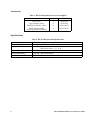
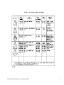
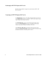
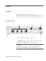
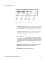
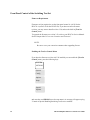
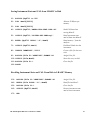
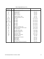
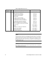
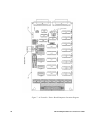
Contents
General Information . . . . . . . . . . . . . . . . . . . . . . . . . . . . . . . . . . . . . . . . . . . . . . . . . . . 3
Introduction . . . . . . . . . . . . . . . . . . . . . . . . . . . . . . . . . . . . . . . . . . . . . . . . . . . . . . . 3
Description . . . . . . . . . . . . . . . . . . . . . . . . . . . . . . . . . . . . . . . . . . . . . . . . . . . . . . . 3
Accessories . . . . . . . . . . . . . . . . . . . . . . . . . . . . . . . . . . . . . . . . . . . . . . . . . . . . . . . 4
Specifications . . . . . . . . . . . . . . . . . . . . . . . . . . . . . . . . . . . . . . . . . . . . . . . . . . . . . 4
Installation . . . . . . . . . . . . . . . . . . . . . . . . . . . . . . . . . . . . . . . . . . . . . . . . . . . . . . . . . . . . 5
Introduction . . . . . . . . . . . . . . . . . . . . . . . . . . . . . . . . . . . . . . . . . . . . . . . . . . . . . . . 5
Initial Inspection . . . . . . . . . . . . . . . . . . . . . . . . . . . . . . . . . . . . . . . . . . . . . . . . . . 5
Preparation For Use . . . . . . . . . . . . . . . . . . . . . . . . . . . . . . . . . . . . . . . . . . . . . . . 5
Line Voltage and Fuse Selection . . . . . . . . . . . . . . . . . . . . . . . . . . . . . . . . . . . 6
Fuse Replacement . . . . . . . . . . . . . . . . . . . . . . . . . . . . . . . . . . . . . . . . . . . . . . . . . 6
Power Cable . . . . . . . . . . . . . . . . . . . . . . . . . . . . . . . . . . . . . . . . . . . . . . . . . . . . . . 6
Positioning the HP 8711B Option K40 Test Set . . . . . . . . . . . . . . . . . . . . 8
Connecting the HP 8711B Option K40 Test Set . . . . . . . . . . . . . . . . . . . . 8
Operation . . . . . . . . . . . . . . . . . . . . . . . . . . . . . . . . . . . . . . . . . . . . . . . . . . . . . . . . . . . . . 9
Introduction . . . . . . . . . . . . . . . . . . . . . . . . . . . . . . . . . . . . . . . . . . . . . . . . . . . . . . . 9
Front Panel Features . . . . . . . . . . . . . . . . . . . . . . . . . . . . . . . . . . . . . . . . . . . . . . 9
Rear Panel Features . . . . . . . . . . . . . . . . . . . . . . . . . . . . . . . . . . . . . . . . . . . . . . 11
Operating Theory . . . . . . . . . . . . . . . . . . . . . . . . . . . . . . . . . . . . . . . . . . . . . . . . 12
Programming the HP 8711B Option K40 Test Set . . . . . . . . . . . . . . . . . 13
Front Panel Control of the Switching Test Set . . . . . . . . . . . . . . . . . . . . . 14
Programming Considerations . . . . . . . . . . . . . . . . . . . . . . . . . . . . . . . . . . . . . 16
Performance Tests . . . . . . . . . . . . . . . . . . . . . . . . . . . . . . . . . . . . . . . . . . . . . . . . . . . . 20
Adjustments . . . . . . . . . . . . . . . . . . . . . . . . . . . . . . . . . . . . . . . . . . . . . . . . . . . . . . . . . . 21
Replaceable Parts . . . . . . . . . . . . . . . . . . . . . . . . . . . . . . . . . . . . . . . . . . . . . . . . . . . . 22
Manual Backdating Changes . . . . . . . . . . . . . . . . . . . . . . . . . . . . . . . . . . . . . . . . . 26
Service . . . . . . . . . . . . . . . . . . . . . . . . . . . . . . . . . . . . . . . . . . . . . . . . . . . . . . . . . . . . . . . 27
HP 8711B Option K40 User’s and Service Guide
1
Tables
Table 1. HP 8711B Option K40 Accessories Supplied . . . . . . . . . . . . . . . . . 4
Table 2. HP 8711B Option K40 Specifications . . . . . . . . . . . . . . . . . . . . . . . . 4
Table 3. Power Requirements . . . . . . . . . . . . . . . . . . . . . . . . . . . . . . . . . . . . . . . . . 5
Table 4. AC Power Cables Available . . . . . . . . . . . . . . . . . . . . . . . . . . . . . . . . . . 7
Table 5. RF Path / Switch Positions . . . . . . . . . . . . . . . . . . . . . . . . . . . . . . . . . . 14
Table 6. Replaceable Parts . . . . . . . . . . . . . . . . . . . . . . . . . . . . . . . . . . . . . . . . . . . 21
Figures
Figure 1. HP 8711B Option K40 Front Panel Features . . . . . . . . . . . . . . . . 9
Figure 2. HP 8711B Option K40 Rear Panel Features . . . . . . . . . . . . . . . . 11
Figure 3. HP 8711B Option K40 Major Component Locations . . . . . . . . 23
Figure 4. HP 8711B Option K40 Overall Schematic Diagram . . . . . . . . 25
Figure 5. HP 8711B Option K40 RF Switch Wiring Diagram . . . . . . . . . 26
Figure 6. HP 8711B Option K40 Block Diagram . . . . . . . . . . . . . . . . . . . . . 27
Figure 7. A1 Controller / Driver Board . . . . . . . . . . . . . . . . . . . . . . . . . . . . . . 28
Component Locations Diagram
Figure 8. A1 Controller / Driver Board Schematic Diagram . . . . . . . . . . 29
2
HP 8711B Option K40 User’s and Service Guide
General Information
Introduction
This manual contains information required for installing, operating, and
servicing the HP 8711B Option K40 RF Switching Test Set.
Description
The HP 8711B Option K40 RF Switching Test Set is specifically designed for
use with the HP 871xA/C Network Analyzer. The HP 8711B Option K40
enables the network analyzer to measure 14 S-Parameters of a four port DUT
without disconnecting and reconnecting the DUT.
The HP 8711B Option K40 utilizes the I-Basic capabilities of the HP 871x to
control its RF switches. The interface between the HP 871x Network Analyzer
and the HP 8711B Option K40 is provided through the parallel port interface.
The HP 8711B Option K40 provides a second parallel connector so printer
capabilities will not be interrupted or a second switching test set may be added.
Power for the HP 8711B Option K40 is provided by its own internal power
supply. A DC output connector is provided on the rear panel to power additional
switching test sets.
HP 8711B Option K40 User’s and Service Guide
3
Accessories
Table 1. HP 8711B Option K40 Accessories Supplied
Description
Power Cord
Type N Jumper Cables
Parallel Port Interface Cable
HP 8711B Option K40
Operating and Service Manual
Quantity
1
2
1
1
Part Number
8120-1348
8120-4782
08711-60123
08711-90153
Specifications
Table 2. HP 8711B Option K40 Specifications
Parameter
Frequency Range
Insertion Loss
Source Match
Switch Repeatability
Impedance
4
Specification
300 kHz to 1.3 GHz
<1.0 dB (Transmission to Port 1, 2, 3, or 4)
(Reflection to Port 1, 2, 3, or 4)
≥25 dB All Ports
±0.03 dB (Per switch contact)
50 Ω
(All ports)
HP 8711B Option K40 User’s and Service Guide
Installation
Introduction
This chapter describes how to install the HP 8711B Option K40 Test Set into a
measurement system. The topics include initial inspection and preparation for
use.
Initial Inspection
Inspect the shipping container (including cushioning material) for damage. If the
shipping container or cushioning material is damaged, it should be kept until the
contents of the shipment have been checked for completeness. The contents of
the shipment should be as follows:
HP 8711B Option K40
Operating and Service Manual, HP part number 08711-90153
Power Cord, HP part number 8120-1348
HP 8711B Option K40 Parallel Port Interface Cable,
HP part number 08711-60123
HP 8711B Option K40 Type N Jumper Cables (2),
HP part number 8120-4782
Front Handle Kit HP p/n 5063-9226
Check the instrument mechanically and electrically. If the instrument is
damaged, defective, or incomplete, notify the nearest Hewlett-Packard Sales and
Service Office. Keep the shipping material for the carrier’s inspection. The HP
office will arrange for repair or replacement without waiting for settlement of the
claim.
Preparation For Use
Power Requirements
Table 3. Power Requirements
Characteristic
Input Voltage
Frequency
Power
Requirement
90 V to 250 V
48 Hz to 66 Hz
55 VA Max
HP 8711B Option K40 User’s and Service Guide
5
Line Voltage and Fuse Selection
CAUTION:
To prevent damage to the instrument, make sure that the 3.0 A, 250 V fuse is
installed.
Measure the ac line voltage to determine if the line voltage is within the input
voltage range specified in Table 3.
A single 3.0 A, 250 V fuse is used over the entire voltage range. This fuse is
located in the power-line module on the rear panel of the instrument.
Fuse Replacement
1.
Pry out the fuse carrier.
2.
Insert the fuse of the proper rating (3.0 A, 250 V).
3.
Place the fuse carrier back into the line module.
Power Cable
In accordance with international safety standards, this instrument is equipped with
a three-wire power cable. When connected to an appropriate power line outlet,
this cable grounds the instrument cabinet. Table 4 shows the styles of plugs
available on power cables supplied with Hewlett-Packard instruments. The HP
part numbers indicated are part numbers for the complete power cable and plug
set. The specific type of power cable and plug shipped with the instrument
depends upon the country of shipment destination.
6
HP 8711B Option K40 User’s and Service Guide
Table 4. AC Power Cables Available
HP 8711B Option K40 User’s and Service Guide
7
Positioning the HP 8711B Option K40 Test Set
The HP 8711B Option K40 is designed to be placed under the HP 871x RF
Network Analyzer.
Connecting the HP 8711B Option K40 Test Set
The REFLECTION connector of the HP 8711B Option K40 connects directly
to the REFLECTION connector of the HP 871x RF Network Analyzer using a
Type N Jumper cable (HP p/n 8120-4782).
The TRANSMISSION connector of the HP 8711B Option K40 connects
directly to the TRANSMISSION connector of the HP 871x RF Network
Analyzer using a Type N Jumper cable (HP p/n 8120-4782).
The PARALLEL PORT INPUT of the HP 8711B Option K40 connects
directly to the PARALLEL PORT of the HP 871x RF Network Analyzer using
the Parallel Port Interface Cable (HP p/n 08711-60123).
8
HP 8711B Option K40 User’s and Service Guide
Operation
Introduction
This chapter describes the front and rear panel features of the
HP 8711B Option K40. The I-Basic program example provided in this chapter
can be used as an aid in writing a program to control the HP 8711B Option K40.
Front Panel Features
2
3
4
5
1
Figure 1. HP 8711B Option K40 Front Panel Features
1. POWER ON switch controls the line power to the HP 8711B Option K40.
2. PORT 1 through PORT 4 connect to the device under test.
CAUTION:
Do not input more than +20 dBm or 7 Vdc to these ports or damage to the
internal RF switches or the HP 871x Network Analyzer will result.
HP 8711B Option K40 User’s and Service Guide
9
3.
REFLECTION connector connects directly to the reflection connector on
the HP 871x Network Analyzer.
CAUTION:
Do not input more than +30 dBm or 7 Vdc to this connector or damage to the
internal RF switches will result.
4. TRANSMISSION connector connects directly to the transmission
connector on the HP 871x Network Analyzer.
CAUTION:
Do not input more than +30 dBm or 7 Vdc to this connector or damage to the
internal RF switches will result.
5. Ground Connector provides a front panel ground connection.
10
HP 8711B Option K40 User’s and Service Guide
Rear Panel Features
Figure 2. HP 8711B Option K40 Rear Panel Features
1. PARALLEL PORT INPUT is a 25-pin subminiature type connector. This
connector supplies the control signals to switch the HP 8711B Option K40.
In pass through mode, it also accepts signals required to drive a printer.
2. PARALLEL PORT OUTPUT is a 25-pin subminiature type connector.
This connector supplies the control signals to either control another
switching test set or a printer.
3. PRINTER/TEST SET switch controls the function of the Parallel Port
Output connector. When switched to Printer, a printer can be connected to
the Parallel Port Output connector. When this switch is positioned to Test
Set, an additional test set can be controlled from the Parallel Port Output
connector.
4. DC OUTPUT connector provides a +5 V and +24 V output to drive an
additional test set (for example, HP 8711A Option K12).
5. Power Module is the instrument power receptacle.
HP 8711B Option K40 User’s and Service Guide
11
Operating Theory
The HP 8711B Option K40 Switching Test Set is comprised of four mechanical
RF switches, a controller board, and a power supply.
The RF switches are controlled by the I-Basic capabilities of the HP 871x
Network Analyzer. The HP 871x RF Network Analyzer’s Parallel Port output
connector is utilized for an interface to control the 8711B Option K40.
The following description illustrates how the HP 8711B Option K40 expands the
capabilities of the HP 871x RF Network Analyzer from a single port analyzer to
a four port analyzer.
The reflection path and transmission path first encounter RF switch S4 (refer to
the HP 8711B Option K40 block diagram in Figure 6). The switch is a transfer
switch which changes the function of the reflection and transmission paths to
both being reflection/transmission paths. These two RF paths lead to RF switch
S1 and S3. RF switch S1 divides this path into Port 1 and Port 2 connections.
RF switch S3 divides this path into RF switch S1 and S2. S2 further divides the
path into Port 3 and Port 4. This RF diagram provides a means to make 14
different S-Parameter measurements on a single four port device.
12
HP 8711B Option K40 User’s and Service Guide
Programming the HP 8711B Option K40
In order to control the RF switches in the HP 8711B Option K40, an I-Basic
program must be written. Below is an example of a program selecting an RF
path from the transmission connector to the Port 1 connector. Refer to Table 5
showing the necessary switch positions for each of the ten possible paths along
with the appropriate I-Basic command.
The HP 8711B Option K40/K12 requires additional memory space for storing
instrument state and calibration data. The HP 8711A provides 46 kilobytes of
nonvolatile memory for instrument state and calibration data. A new SCPI
command has been set up to provide up to 1.5 Mbytes of memory space for
storing instrument state, calibration data, and I-BASIC programs in I-BASIC
memory.
Following are two example programs demonstrating how to use the
capabilities for learn strings less than 32,767 bytes long, and for learn
strings greater than 32,767 bytes not exceeding 80,000 bytes long. Also
following is an example program demonstrating how to save the
instrument state and calibration data from I-BASIC memory to disk and
back to I-BASIC memory.
For additional programming assistance, refer to Section 9, of the standard
Operating and Programming Manual.
NOTE:
HP 8711A instruments with serial numbers below 3325A01275 require special
Option H02 or upgraded to firmware Rev. 2.10.
HP 8711B Option K40 User’s and Service Guide
13
Front Panel Control of the Switching Test Set
Firmware Requirments
Firmware revision required to use the front panel control is A.03.50 for the
HP 8711A (or B.03.50 for the HP 8711B). If you have an earlier firmware
revision, you may want to install revision 3.50, and use the built-in [Test Set
Control] menu.
To upgrade the firmware to revision 3.50, refer to your HP 871x Service Manual.
See the chapter titled "Correction Constants and Firmware".
NOTE:
Be sure to save your correction constants when upgrading firware.
Enabling the Test Set Control Menu
If you have the firmware revision A.03.50 installed you can enable the [Test Set
Control] menu, press the following keys:
SYSTEM
OPTIONS
System
Config
Options
Setup
Special
Options
and enter the work BEARS (case does not matter). A message will appear saying
"Control of Special Handling Switching Test Set now enabled"
14
HP 8711B Option K40 User’s and Service Guide
Test Set Control Menu
Press the following keys to enter the [Test Set Control] menu (this menu is
disabled by default, but can be enabled by a keyword, as described above).
SYSTEM
OPTIONS
System
Config
Test Set
Control.
Use the softkeys to select 8711A K04 as the model of your switching test set.
Test Set
Model/Opt
8711A K04
Prior Menu
Control
on/OFF
When set to "ON", the analyzer will write to the test set to configure the
connections. Writing is done when you recall an instrument state, turn on power,
or change a test set setting.
Select the test set port that you want to use as the reflection port (RF OUT)
Reflection To
Port#
or, select the test set port that you want to use as the transmission port (RF IN).
Transmissn To
Port#
HP 8711B Option K40 User’s and Service Guide
15
Programming Considerations
The design of the controller board is configured such that it has two latches for
each RF switch driver. Since an RF switch could end up straddling the different
latch inputs, an RF switch could be driven in two different directions at the same
time. In order to prevent this from happening, it is recommended that the latches
be cleared prior to changing their positions. Refer to lines 730 to 750. It is also
advisable to clear the latches after all switch positions have been completed.
This will prevent current flow in RF S4 which does not have a current interrupt
circuit in it. Refer to lines 810 to 830. Wait statements between each switch
command are necessary to assure that proper switching occurs. Refer to line
780.
Table 5. RF Path/Switch Positions
RF PATH
RF SWITCH POSITION
Connector
From - To
S4
Command
S3
S2
S1
Conn
Command
Conn
Command
Conn
Trans - Port 1 J2-J1 WRITEIO
15,3;2
--
--
--
--
1-2
WRITEIO
15,3;34
Trans - Port 2 J2-J1 WRITEIO
15,3;2
--
--
--
--
3-2
WRITEIO
15,3;36
Trans - Port 2 J3-J1 WRITEIO
15,3;1
1-C
WRITEIO
15,3;4
--
--
3-4
WRITEIO
15,3;34
Trans - Port 3 J3-J1 WRITEIO
15,3;1
2-C
WRITEIO
15,3;8
1-C
WRITEIO
15,3;16
--
--
Trans - Port 4 J3-J1 WRITEIO
15,3;1
2-C
WRITEIO
15,3;8
2-C
WRITEIO
15,3;33
--
--
Refl - Port 1 J2-J4 WRITEIO
15,3;1
--
--
--
--
1-2
WRITEIO
15,3;34
Refl - Port 2 J2-J4 WRITEIO
15,3;1
--
--
--
--
3-2
WRITEIO
15,3;36
Refl - Port 2 J3-J4 WRITEIO
15,3;2
1-C
WRITEIO
15,3;4
--
--
3-4
WRITEIO
15,3;34
Refl - Port 3 J3-J4 WRITEIO
15,3;2
2-C
WRITEIO
15,3;8
1-C
WRITEIO
15,3;16
--
--
Refl - Port 4 J3-J4 WRITEIO
15,3;2
2-C
WRITEIO
15,3;8
2-C
WRITEIO
15,3;33
--
--
16
Conn
Command
HP 8711B Option K40 User’s and Service Guide
Selecting RF Path Trans to Port 1
700 Setup1: !
710
DISP "RF Path Trans to Port 1 (S4, S1)"
Displays RF path.
720
OUTPUT 800;"diag:cpu:mem 33554694,-1"
Selects test set.
(-1 = Test Set)
(0 = Printer)
730
FOR I=0 TO 224 STEP 32
740
WRITEIO 15,3;I
750
NEXT I
760
WAIT .03
770
WRITEIO 15,3;2
780
WAIT .03
790
WRITEIO 15,3;34
800
WAIT .03
810
FOR I=0 TO 224 STEP 32
820
WRITEIO 15,3;I
830
NEXT I
840
OUTPUT 800;"diag:cpu:mem 33554694,0"
Lines 730, 740, and 750
clear latches prior to
inputting new data.
Switches RF Switch S4.
Switches RF Switch S1.
Lines 810, 820, and 830
clear latches, remove
current from RF switches.
Selects printer.
(-1 = Test Set)
(0 = Printer)
850 RETURN
HP 8711B Option K40 User’s and Service Guide
17
Saving Instrument State and CAL <32,767 Bytes Long
10
DIM
Mem1$[20000]
20
DIM
Mem2$[20000]
Allocate 20 Kbytes per
memory.
...
50
OUTPUT @Hp8711;"MMEM:STOR:STAT:CORR ON"
Send Cal Data when
storing Mem1$.
60
OUTPUT @Hp8711;"SYSTEM:SET:LRNLong?"
Read instrument state
and cal data into Mem1$.
70
ENTER @Hp8711 USING "-K"; Mem1$
Read memory 1 from the
analyzer.
...
160
Put Mem1$ back into the
instrument.
OUTPUT @Hp8711;Mem1$
Saving Instrument State and CAL >32,767 Bytes Long
10
DIM
Mem1$ (1:4) [20000]
20
DIM
Mem2$ (1:4) [20000]
Allocate 80 Kbytes per
memory.
...
50
OUTPUT @Hp8711;"MMEM:STOR:STAT:CORR ON"
Send Cal Data when
storing Mem1$.
60
OUTPUT @Hp8711;"SYSTEM:SET:LRNLong?"
Read instrument state
and cal data into Mem1$.
70
ENTER @Hp8711 USING "%,-K"; Mem1$(*)
Read memory 1 from the
analyzer.
...
160
18
OUTPUT @Hp8711;Mem1$(*)
Put Mem1$ back into the
instrument.
HP 8711B Option K40 User’s and Service Guide
Saving Instrument State and CAL from I-BASIC to Disk
10
ASSIGN @Hp8711 to 800
20
DIM
Mem1$[20000]
30
DIM
Mem2$[20000]
40
OUTPUT @Hp8711;"MMEM:STOR:STAT:CORR ON"
Send Cal Data when
storing Mem1$.
50
OUTPUT @Hp8711;"SYSTEM:SET:LRNLong?"
Read instrument state
and cal data into Mem1$.
60
ENTER @Hp8711 USING "-K"; Mem1$
Read memory 1 from the
analyzer.
70
OUTPUT @Hp8711;Mem1$
Put Mem1$ back into the
instrument.
80
CREATE "MEMFILE1",20000
Create a file if it does not
exist.
90
ASSIGN @File TO "MEMFILE1";FORMAT ON
Assign IO to file.
Allocate 20 Kbytes per
memory.
100 OUTPUT @File;Mem1$
Store this array to disk.
110 ASSIGN @File TO *
Close the file.
120 PAUSE
Recalling Instrument State and CAL From Disk to I-BASIC Memory
130
ASSIGN @File TO "MEMFILE1";FORMAT ON
Assign IO to file.
140
ENTER @File USING "-K"; Mem2$
Read file into Mem 2.
150
ASSIGN @File TO *
Close the file.
160
OUTPUT @Hp8711;Mem2$
Restore instrument state
and cal into instrument.
170
END
HP 8711B Option K40 User’s and Service Guide
19
Performance Tests
There are no performance tests for this instrument.
20
HP 8711B Option K40 User’s and Service Guide
Adjustments
There are no adjustments for this instrument.
HP 8711B Option K40 User’s and Service Guide
21
Replaceable Parts
Introduction
This chapter provides replaceable parts and ordering information.
Replaceable Parts List
The replaceable parts list is arranged in alpha-numerical order by reference
designator and consists of the following information:
a. Reference designator
b. Total quantity (Qty) in the instrument
c. Description of the part
d. Hewlett-Packard part number
Ordering Parts
To order a part listed in the replaceable parts table, quote the Hewlett-Packard
part number, indicate the quantity required, and address the order to your nearest
Hewlett-Packard office.
To request information on a part that is not listed in the replaceable parts table,
include the instrument model number, instrument identification number, and a
description of the part and its function. Address the inquiry to the nearest
Hewlett-Packard office.
22
HP 8711B Option K40 User’s and Service Guide
Table 6. Replaceable Parts (1 of 2)
Reference
Designator
A1
A2
DS1
F1
F2, F3
J7
J1-J6
W2,W4
W1,W3
W5
W6,W15,W16
W7
W8
W9,W10
W11
W12
W13
W14
S1
S2,S3
S4A
S4B
S5
Qty
1
1
1
2
2
1
6
2
2
1
3
1
1
2
1
1
1
1
1
2
1
1
1
2
1
2
1
4
Description
CONTROLLER/DRIVER BD
POWER SUPPLY
LED-YELLOW
FUSE 3 A 250 V F
FUSE 3 A 250 V F
CONNECTOR DC 3-PIN
TYPE N BULKHEAD CONN
RF CABLE
RF CABLE
RF CABLE
RF CABLE
RF CABLE
RF CABLE
RF CABLE
RF SWITCH CABLE ASSY
PRINTER/TEST SET SWITCH ASSY
DC CABLE ASSY
AC LINE CABLE ASSY
RF SWITCH, TRANSFER
RF SWITCH, SPDT
RF SWITCH, SPDT
RF SWITCH, TRANSFER
ROCKER SWITCH
TRIM-SIDE (NOT SHOWN)
FRAME-REAR
STRUT-SIDE
FRAME-FRONT
STDF REAR PANEL (NOT SHOWN)
HP 8711B Option K40 User’s and Service Guide
Part Number
08711-60125
0950-2252
1990-0858
2110-0780
2110-0003
1251-6781
5061-5386
08711-20158*
08711-20157*
08711-20119*
08711-20120*
08711-20121*
08711-20141*
08711-20123*
08711-60128*
08711-60129
08711-60127*
87130-60007
33312-60004
70612-60003
08711-60157
33313-60001
3101-3008
5041-9170
5021-5802
5021-5887
5022-1187
5041-9188
23
Table 6. Replaceable Parts (2 of 2)
Reference
Designator
Qty
4
1
1
1
1
1
1
1
1
1
2
1
1
1
1
1
1
Description
Part Number
FOOT-FM .5M (NOT SHOWN)
TRM STRIP (NOT SHOWN)
CAP-FRONT (NOT SHOWN)
CAP-REAR (NOT SHOWN)
STRAP ASSY
COVER TOP (NOT SHOWN)
COVER BOTTOM (NOT SHOWN)
COVER-SIDE W/O RH (NOT SHOWN)
COVER-SIDE W RH (NOT SHOWN)
FRONT HANDLE KIT (NOT SHOWN)
TYPE N JUMPER CABLES (NOT SHOWN)
REAR-PANEL
DECK
INTERFACE CABLE (NOT SHOWN)
FRONT-PANEL DRESS
FRONT-PANEL SUB
BRACKET, RF SWITCH
5041-9167
5041-9176
5041-9186
5041-9187
5063-9210
5002-1047
5002-1088
5002-3913
5002-3736
5063-9226
8120-4782
08711-00053*
08711-00054*
08711-60123
08711-00077*
08711-00076*
08711-00063*
NOTE:
The part numbers indicated (*) are unique to this special option. To order these
replacement parts, please contact NA MID Support Group with the part number,
module/model number and option number. If ordering parts through your local
HP Sales and Service Office, specify that asterisk parts are ordered through the
NA MID Support Group.
NOTE:
Special Options are built to order, therefore long lead times may be encountered
when ordering replacement parts.
24
HP 8711B Option K40 User’s and Service Guide
Figure 3. Major Component Locations
HP 8711B Option K40 User’s and Service Guide
25
Manual Backdating Changes
This manual has been written for and applies directly to all
HP 8711B Option K40 Test Sets. However, because there are no earlier versions
of this instrument, this chapter contains no applicable information.
26
HP 8711B Option K40 User’s and Service Guide
Service
This chapter provides a schematic, RF switch wiring diagram, and a block
diagram of the assemblies in the HP 8711B Option K40 Test Set. Schematic
diagrams of the power supply are not available at this time.
Figure 4. HP 8711B Option K40 Overall Schematic Diagram
HP 8711B Option K40 User’s and Service Guide
27
Figure 5. RF Switch Wiring Diagram
28
HP 8711B Option K40 User’s and Service Guide
Figure 6. HP 8711B Option K40 Block Diagram
HP 8711B Option K40 User’s and Service Guide
29
Figure 7. A1 Controller / Driver Board Component Locations Diagram
30
HP 8711B Option K40 User’s and Service Guide