1
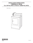
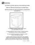
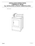
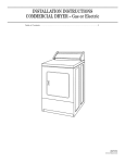
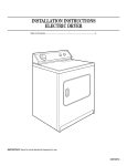
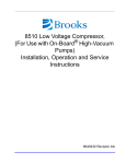
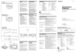
CONSUMER SERVICES TECHNICAL
L-63
EDUCATION GROUP PRESENTS
27”
ELECTRIC & GAS
DRYERS
JOB AID
Part No. 4322260
I
INTRODUCTION
This Job Aid, “27 “ ELECTRIC & GAS DRYERS,” (Part No. 4322260), provides specific information on
the installation, service and repair of Whirlpool 27” dryers.
“27” ELECTRIC & GAS DRYERS” has been compiled to provide the most recent information on
design, features, troubleshooting, service and repair procedures.
GOALS AND OBJECTIVES
The goal of this Job Aid is to provide detailed information that will enable the service technician to
properly diagnose malfunctions and repair Whirlpool 27” electric or gas dryers.
The objectives of the Job Aid are:
The service technician will •
•
•
•
Understand proper safety precautions.
Successfully troubleshoot and diagnose malfunction.
Successfully perform necessary repairs.
Successfully return the dryer to proper operational status.
CORPORATION
WHIRLPOOL CORPORATION ASSUMES NO RESPONSIBILITY
FOR ANY REPAIRS MADE ON OUR PRODUCTS BY ANYONE
OTHER THAN AUTHORIZED SERVICE TECHNICIANS.
© 1997 Whirlpool Corporation, Benton Harbor, MI 49022
PB
TABLE OF CONTENTS
INTRODUCTION .................................................................................................................. II
TABLE OF CONTENTS ...................................................................................................... III
SECTION ONE
GENERAL INFORMATION
Electric Requirements .................................................................................................. 1
Exhaust Requirements for Electric and Gas Dryers .................................................. 5
Gas Requirements for Gas Dryers .............................................................................. 6
Recessed and Closet Installation Instructions ........................................................... 8
SECTION TWO
THEORY OF OPERATION
Controls and Cycles ....................................................................................................................9
Electronic Dryer Control ...........................................................................................................10
Heated Air Circulation............................................................................................................... 11
SECTION THREE
COMPONENT ACCESS .................................................................................................... 13
Removing the Console ..........................................................................................................13
Removing the Timer ..............................................................................................................14
Removing the Clean touch Switch Assembly ........................................................................14
Removing the Push to Start Button .......................................................................................14
Removing the Buzzer ............................................................................................................14
Removing the Electronic Control Board ................................................................................14
Removing the Dryer Top ........................................................................................................14
Replacing the Drum Lamp .....................................................................................................15
Removing the Door Switch ....................................................................................................15
Removing the Toe Panel .......................................................................................................15
Removing the Blower Wheel .................................................................................................16
Replacing the Blower Housing ..............................................................................................16
Replacing the Motor ..............................................................................................................17
Replacing the Operating Thermostat and Bias Heater ..........................................................17
Replacing the Thermal Fuse .................................................................................................17
Replacing the Heating Element .............................................................................................18
Replacing the Burner Assembly ............................................................................................18
Replacing the High Limit Thermostat and Thermal Cutoff ....................................................18
Replacing the Heat Duct Assembly .......................................................................................18
Removing the Dryer Door ......................................................................................................19
Removing the Front Panel .....................................................................................................19
Removing the Belt and Drum ................................................................................................20
Replacing the Front Support Rollers and Shafts ...................................................................20
Replacing the Grille Assembly ..............................................................................................20
Removing the Rear Bulkhead Assembly ...............................................................................21
Reattaching the Rear Bulkhead ............................................................................................21
III
SECTION FOUR
TROUBLESHOOTING AND DIAGNOSIS
Troubleshooting Guide .............................................................................................................23
Electronic Dryer Control Testing .............................................................................................24
SECTION FIVE
TECH TIPS
Wiring Diagrams ........................................................................................................................25
Strip Circuits ..............................................................................................................................27
Model/Serial Number Plate Location .......................................................................................30
Model/Serial Number Designations .........................................................................................30
Product Specification and Warranty Information Source......................................................30
PB
V
Section One
GENERAL INFORMATION
ELECTRICAL REQUIREMENTS
Electrical Requirements for Gas Dryers
Important: Observe all governing codes and ordinances.
Electrical ground is required on this product.
! WARNING
Electrical Shock Hazard
Check with a qualified electrician if you are in doubt as to whether the appliance
is properly grounded. Do Not modify the power supply cord plug. If it will not fit
the outlet, have a proper outlet installed by a qualified electrician.
Improper connection of the equipment-grounding conductor can result in a risk
of electrical shock.
Do Not use an extension cord with this appliance. Such use may result in a fire,
electrical shock or other personal injury.
Do Not have a fuse in the neutral or grounding circuit. This could result in a risk
of electrical shock.
A 120 volt, 60 Hz, AC only 15 or 20 Ampere fused electrical supply is required. A time-delay fuse or
circuit breaker is recommended. It is recommended that a separate circuit serving only this appliance
be provided.
Recommended Grounding Method
3-prong
groundingtype wall
receptacle
Electrical ground is required on this appliance.
➘
DO NOT, UNDER ANY CIRCUMSTANCES,
REMOVE THE POWER SUPPLY CORD GROUND
PRONG.
1
➘
➘
For your personal safety, this appliance must be
grounded. This appliance is equipped with a power
supply cord having a 3-prong grounding plug. (Fig. 1) To
minimize possible shock hazard, the cord must be
plugged into a mating 3-prong grounding type wall
receptacle, grounded in accordance with the National
Electrical Code, ANSI/NFPA 70-1987 or the latest code
and local ordinances. If a mating wall receptacle is not
available, it is the personal responsibility and obligation
of the customer to have a properly grounded 3-prong
wall receptacle installed by a qualified electrician.
3-prong
groundingplug
grounding
prong
➘ power
supply cord
Fig. 1
Electrical Requirements for Electric Dryers
Important: Observe all governing codes and ordinances.
Electrical ground is required on this product.
! WARNING
Electrical Shock Hazard
Check with a qualified electrician if you are in doubt as to whether the appliance
is properly grounded. Do Not modify the power supply cord plug. If it will not fit
the outlet, have a proper outlet installed by a qualified electrician.
Improper connection of the equipment-grounding conductor can result in a risk
of electrical shock.
Do Not have a fuse in the neutral or grounding circuit. This could result in a risk
of electrical shock.
Do Not plug the power supply cord (pigtail) into any receptacle before connecting
the pigtail to the dryer terminal block. This could result in a risk of electrical
shock.
Electrical Connection
A. A three-wire (Fig. 2) or four-wire (Fig. 3),
single phase, 120/240 volt, 60 Hz, AC only
electrical supply is required on a separate
30-ampere circuit, fused on both sides of
the line. A time-delay fuse or circuit
breaker is recommended.
B. Most local codes permit the use of flexible,
30-amp rated, power supply cord (pigtail).
The power cord must be plugged into a
mating 30-amp receptacle (NEMA type
10-30R). A U.L.- listed strain relief must
be installed where the power cord enters
the dryer.
Fig. 3
C. THE DRYER MUST BE CONNECTED
WITH 10-GAUGE MINIMUM COPPER
WIRE ONLY. Do Not use aluminum wire
which could cause a fire.
Fig. 2
D. The power supply cord (pigtail) can be
removed and the appliance can be connected directly to an individual 30-ampere
fuse circuit breaker box through flexible
armored or nonmetallic sheathed, 10gauge minimum copper cable. It is the
personal responsibility and obligation of
2
the customer to contact a qualified electrician to assure that the electrical installation is
adequate and is in conformance with National Electrical Code ANSI/NFPA 70-1987 (or the
latest edition) and local codes and ordinances.
Important:
Allow slack in the line between the wall and the appliance so that it can be
move if servicing is ever necessary.
A U.L.-listed strain relief must be provided at each end of the power supply cable (at the appliance and
at the junction box). Wire sizes (10-gauge COPPER WIRE ONLY) and connections must conform with
the 30-ampere circuit rating.
E. For mobile home installation, the three-wire power supply cord must be removed and the
appliance wiring must be revised. The appliance frame must not be connected to the neutral
terminal, but must be connected to the grounding wire (green) of the power supply cord.
See Alternate electrical connection - mobile home installation, for detailed instructions.
If a four-wire receptacle of NEMA type 14-30R is available, a matching power supply cord (pigtail)
must be used. This cord contains No. 10-gauge copper conductors with spade or ring terminals on the
dryer end and terminating in a NEMA type 14-30P plug on supply end. The fourth (grounding) must be
identified by a green cover and the neutral conductor by a white cover. Cord should be at least three
feet long. The four-wire power supply cord and strain relief are not provided with the dryer.
! WARNING
Electrical Shock Hazard
Disconnect power supply cord from the electric supply before making these
changes. Use a new power supply cord.
Failure to do so may result in electrical shock.
Grounding Instructions
This appliance must be connected to a grounded metal, permanent wiring system; or an equipmentgrounding conductor must be run with the circuit conductors and connected to the equipment-grounding
terminal or lead on the appliance.
Electrical grounding is required on this appliance.
This appliance is manufactured with the neutral terminal connected to the frame.
Make sure power supply is turned off.
A. If local codes permit connection of the frame-grounding conductor to the neutral wire of the power
supply cord:
1. Loosen the terminal block cover hold-down screw. Swing cover open to the right.
2. Attach a U.L.-listed strain relief to the dyer through the power supply cord hole. Place the
power supply cord or direct wire through the strain relief.
3. Connect the neutral wire on the power supply cord to the center, silver-colored terminal of the
terminal block and connect the other wires to the outer terminals.
3
4. IF YOUR POWER SUPPLY CORD OR DIRECT WIRING HAS PLAIN WIRE ENDS, FOLLOW
THESE STEPS:
a. Strip outer covering back 3 inches from the end exposing the 3 wires.
b. Strip the insulation back 1 inch from the end of each wire. Form the bare wire to “U”
shaped
hook.
c. Loosen, do not remove, the center, silver-colored screw of the terminal block.
d. Slide the end of the neutral (white or center) wire under the screw head with the open side
of the hook on the right. Squeeze the wire together to form a loop.
e. Tighten the screw firmly.
f.
Connect the remaining 2 wires to the outer screws the same way. Tighten screws firmly.
5. Close the terminal block cover and tighten screw.
6. Tighten screws on strain relief.
B. If local codes DO NOT permit frame grounding to the neutral wire of the power supply cord:
1. Loosen the terminal block cover hold-down screw. Swing cover open to the right.
2. Attach a U.L.-listed strain relief to the dryer through the power supply cord hole. Place the
power supply cord or direct wire through the strain relief.
3. Remove the grounding wire (green) from the external grounding connector and fasten under
center silver-colored terminal block screw.
4. Connect the neutral wire of the power supply cord to the center silver-colored terminal of the
terminal block and connect the other wires to the outer terminals.
5. Connect a separate copper grounding wire (No. 10 minimum) to a grounded cold water pipe
by means of a clamp and then to the frame of the appliance at the external grounding connector.
Use Part No. 685463 grounding wire and clamp assembly. Do Not ground to a gas supply
pipe or hot water pipe. Do not connect the power supply cord to electric power supply until
appliance is permanently grounded.
6. Close the terminal block cover and tighten screw.
7. Tighten screws on strain relief.
C. If connecting to a four-wire electrical system (mobile home):
1. Loosen the terminal block cover hold-down screw. Swing cover open to the right.
2. Attach a U.L.-listed strain relief to the dryer through the power supply cord hole. Place the
power supply cord or direct wire thought the strain relief.
3. Remove the grounding wire (green/yellow) from the external grounding connector and fasten
under the center, silver-colored terminal block screw.
4. Connect the grounding wire (green) of the power supply cord to the external grounding connector.
5. Connect the neutral wire (white) of the power supply cord to the center, silver-colored terminal
of the terminal block and connect the other wires to the outer terminals.
6. Close the terminal block cover and tighten screw.
7. Tighten screws on strain relief.
4
Exhaust Requirements for Gas and Electric Dryers
! WARNING
Fire Hazard
Do Not use nonmetal, flexible duct. Do Not use metal duct smaller that four inches in diameter. Do
Not use exhaust hoods with magnetic latches. Improper air supply for exhausting may result in a
fire. Check that exhaust system is not longer than specified. Exhaust systems longer than specified
will:
•
Accumulate lint
•
Shorten the life of the product
•
Reduce performance and result in longer drying times and increased energy usage.
Failure to follow these specifications may result in a fire.
Do Not exhaust dryer into a chimney, furnace cold air duct, attic or crawl space, or any other duct
used for venting. Clean the exhaust system every other year. Do Not install flexible duct under
wall, ceiling or floor materials. Accumulated lint could result in a fire or cause moisture damage.
Four inch Rigid Metal Duct is preferred. Four-inch flexible metal duct may be used.
Metal flexible duct must be fully extended and supported when the dryer is in its final position. DO
NOT KINK OR CRUSH THE DUCT. The metal flexible duct must be completely open to allow adequate
exhaust air to flow.
Plan installation to use the fewest number of elbows and turns. Allow as much room as possible when
using elbows or making turns. Bend duct gradually to avoid kinking. Remove excess flexible duct to
avoid sagging and kinking that may result in reduced air flow.
Use duct tape to seal all joints.
The Exhaust duct can be routed down, left, right, or straight out the back of the dryer. Space
requirements are provided in the Installation Instructions.
Minimum length of rear exhaust system depends upon the type of duct used, number of elbows and
the type of exhaust hood. The maximum length for both rigid and flexible ducts is shown in chart.
Side or bottom exhaust maximum length is 16 feet with two external elbows.
Exhausting the dryer outside is preferred.
Four inch Rigid Metal Duct is preferred. Four-inch flexible metal duct may be used.
Metal flexible duct must be fully extended and supported when the dryer is in its final position. DO
NOT KINK OR CRUSH THE DUCT. The metal flexible duct must be completely open to allow adequate
exhaust air to flow.
5
If the dryer is installed in a confined area such as a bedroom, bathroom, or closet, it must be
exhausted to the outside and provisions must be made for enough air for combustion and ventilation.
Check governing codes and ordinances. Also refer to the Recessed Installation Instructions.
An Exhaust hood should cap the exhaust duct to prevent exhausted air from returning to the dryer.
The outlet of the hood must be a least 12 inches from the ground or any object that may be in the path
of the exhaust.
Four-inch outlet hood is preferred, however, a 2 1/2 inch outlet exhaust hood may be used with
systems ten feet or less. (This outlet creates greater back pressure than other hood types.)
Exhaust kits are available that direct filtered exhaust air inside to conserve energy during the winter
months. Before installing, check that using this type of kit does not violate local codes and ordinances.
Using one of these kits may result in excessive moisture in the home. This may cause problems and
could increase the drying time. The filter must be cleaned regularly to avoid excessive lint buildup
which can affect the dryer’s performance.
Mobile home installation. This appliance is suitable for mobile home installations. The installation of
the dryer must conform to the Manufactured Home Construction and Safety Standard, Title 24 CFR,
Part 3280 (formerly the Federal Standard for Mobile Homes Constructions and Safety, Title 24, HUD
Part 280, 1975) or the latest edition.
Mobile home exhaust requirements: The dryer must have an outside exhaust. If the dryer is
exhausted through the floor and the area under the mobile home is enclosed, the exhaust system
must terminate outside the enclosed area. Extension beyond the enclosure will prevent lint and
moisture buildup under the mobile home.
Secure dryer: For mobile home use, gas dryers must be securely fastened to the floor. Whirlpool Kit
No. 346764 is available at your local parts distributor or Whirlpool Service Center.
For best efficiency the exhaust system should be designed
to conform to the specifications in the Whirlpool Exhaust Guide,
Part No. LIT603197-B. (Fig. 4)
Fig. 4
Gas Requirements for Gas Dryers
Important: Observe all governing codes and ordinances.
! WARNING
Fire Hazard
Connect dryer to a regulated gas supply. L.P. gas supply must not exceed
a pressure of 13” water column. This must be checked by a qualified
person before installing the dryer. Use new, flexible tubing. Old tubing
may leak. All connections must be wrench-tightened. Do Not check for
gas leaks using an open flame. Failure to follow these instructions could
result in a fire or explosion.
6
A. This installation must conform with American National Standard, National Fuel Gas Code ANSI
Z223.1 - 1984, and local codes and ordinances.
B. Input ratings shown on the rating plate (serial tag) are for elevations up to 2,000 feet, ratings
should be reduced at a rate of 4% for each 1,000 feet above sea level.
C. Check that this dryer is equipped with the correct burner for the particular type of gas in the home.
Burner information will be found on the rating plate in the door well of the appliance.
D. This dryer is equipped to be used with NATURAL GAS, certified by A.G.A., and for manufactured
mixed and L.P. gases with appropriate conversion. No attempt shall be made to convert appliances
from the gas specified on the rating plate for use with different gas without consulting the serving
gas supplier. Conversion must be done by a qualified service technician. Gas conversion
kit part numbers are listed on the gas valve burner base.
E. Provide a gas supply line to the dryer location. When rigid pipe is used, it should be 1/2 inch IPS.
When acceptable to the gas supplier, 3/8 inch-approved tubing may be used for lengths under 20
feet. For lengths over 20 feet, larger tubing should be used. Pipe-joint compounds resistant to the
action of L.P. gas must be used.
F. The supply line should be equipped with a shut-off valve. This valve should be in a location that
allows ease of opening and closing. Do Not block access to the shut-off valve.
G. If the dryer is installed in a confined area, such as a bedroom or closet, it must be exhausted to the
outside and provisions made for enough air for combustion and ventilation. (Check covering codes
and ordinances.) Also refer to Recessed or closet installations.
H. If local codes permit, it is recommended that flexible metal tubing, design-certified by the American
Gas Association, be used for connecting the appliance to the gas supply line. (The gas pipe which
extends through the lower rear of the appliance has 3/8 inch male pipe thread.)
I.
If rigid pipe is used as a gas supply line, a combination of pipe fittings must be used to obtain an inline connection to the dryer.
J. Make sure the lower edges of the cabinet, plus the back and bottom sides of the dryer are free of
obstructions to permit adequate clearance of air openings for combustion. See Recessed or closet
installations for minimum spacing requirements.
K. For ease of installation, operation and servicing adequate space should be provided around the
dryer.
L. An 1/8 inch, NPT plugged tapping, accessible for test gauge connection, must be installed
immediately upstream of the gas supply connection to the dryer. The dryer and its individual
shut-off valve must be disconnected from the gas supply piping system during any pressure testing
of that system at test pressures in excess of 1/ psig (3.45 Kpa). The dryer must be isolated from
the gas supply piping system, closing its individual manual shut-off valve during any pressure
testing of the gas supply piping system at test pressures of equal to or less than 1/2 psig (3.45
kPa).
Important: Observe all governing codes and ordinances.
M. The dryer wiring diagram is located behind the lower front access panel. Close the access panel
after servicing. Do Not operate the dryer with the access panel open.
N. If the dryer will not operate, check the following to be sure that:
a. Electric supply is connected.
b. Fuse is intact and tight.
7
c. Door is closed.
d. Controls are set in running or “On” position.
e. Gas shut-off valve is open on supply lines.
Recessed and Closet Installation Instructions
WARNING
! WARNING
Potential Fire Hazard
The dryer must be exhausted outside. If dryer is installed in a closet, the
dryer MUST be exhausted outside. Failure to do so increases the risk of
fire.
This dryer may be installed in a recessed area or closet. (Fig. 5)
The installation spacing is in inches and is the minimum allowable. Additional spacing should be
considered for ease of installation, servicing and compliance with local codes and ordinances. If
closet door is installed, the minimum of unobstructed air openings in top and bottom is required.
Louvered doors with equivalent air openings are acceptable. Closet installation must be exhausted.
Only recessed installations with no cabinet or shelf above the dryer need not be exhausted. Nonexhausted recessed installations require an exhaust deflector.
Other installations must use the minimum dimensions indicated.
To prevent large amounts of lint and moisture from accumulating and to maintain drying efficiency, this
appliance must be exhausted outdoors.
Note: No fuel burning appliance may be installed in the same closet as the dryer.
Fig. 5
8
SECTION TWO
THEORY OF OPERATION
CONSOLE
Fig. 6
TIMER CONTROL
Electronic Dry-Miser
This cycle can be used for most loads. Drying time varies according to type of fabric, size of load and
dryness setting.
•
Set the Cycle Selector Control to the desired dryness.
•
Dryness is determined by an electronic moisture sensor system that “feels” the amount of
moisture in the clothes as they pass over a moisture sensor mounted on the grille assembly
at the front of the drum area. When the selected dryness is reached the dryer goes into a timed
COOL DOWN period of approximately 10 minutes.
•
The End-of-Cycle signal sounds once the cycle is complete.
• The End-of-cycle signal can be turned OFF by pressing the Cycle Signal OFF pad on the
Clean Touch console.
•
The Finish Guard option will tumble the clothes without heat for about 15 seconds every five
minutes until the door is opened and the clothes removed.
•
The Finish Guard option can be turned OFF by pressing the Finish Guard OFF pad on the
Clean Touch console.
Timed Dry Cycle
This cycle will provide up to 80 minutes of heated drying time.
•
The heating cycle is followed by approximately 10 minutes of COOL DOWN.
•
The End-of-Cycle signal sounds once the cycle is complete.
• The End-of-cycle signal can be turned OFF by pressing the Cycle Signal OFF pad on the
Clean Touch console.
•
The Tumble Press portion of the Timed Dry Cycle is designed to provide about 15 minutes of
HEATED TUMBLING followed by 10 minutes of COOL DOWN.
9
Fluff Air Cycle
The Fluff Air Cycle provides up to 30 minutes of unheated drying time.
CLEAN TOUCH CONTROL PAD
The clean touch control pad provides push button control of the following operations:
TEMPERATURE SELECTION - Four levels of temperature ranging from Extra Low to High.
FINISH GUARD - Allows this option to be turned On or OFF.
CYCLE SIGNAL - Allows this option to be turned On or OFF.
PUSH-TO-START KNOB
This knob must be pushed to start the dryer. The door must be closed for the dryer to operate. If the
door is opened during any drying cycle, the dryer will not operate again until the Push-to-Start knob is
pushed again.
“C” VERSION ELECTRONIC DRYER CONTROL
The “C” version dryer control system consists of an electronic control board located in the console
area and a moisture sensor attached to the lint screen grille inside the dryer drum. The dryer control
system measures the resistance across the moisture sensor during the automatic dry cycle. The
electronic control board turns power to the timer motor on and off based on input from the moisture
sensor.
Theory of Operation
When a cycle is selected, Timer Switch 1 will be closed. This applies 120VAC through the orange/
white wire to the electronic control board. Timer Switch 0 will be open if the selected cycle is not a
timed dry cycle, so there is no alternate path for current flow through the timer motor. (Fig. 7)
W/BK
T/W
T/W
Fig. 7
10
The electronic control looks at the input from the moisture sensor to see if the clothes are wet or dry.
The moisture sensor will show continuity (short) if the clothes are wet and show NO continuity (open)
if the clothes are dry.
If the clothes are wet, the Triac on the electronic control board will block power to the timer motor, and
the timer motor will not advance.
If the clothes are dry or there are no clothes in the dryer the Triac on the electronic control board will
allow power to flow to the timer motor causing it to advance.
During the last 10 minutes of the Regular Cycle, (the last 15 minutes of the Permanent Press Cycle)
and any Timed Dry Cycle, Timer Switch 0 will be closed. This will allow the timer motor to advance
regardless of the condition at the moisture sensor. Timer Switch 0 bypasses the electronic control.
(Fig. 8)
W/BK
T/W
T/W
Fig. 8
Heated Air Circulation
Room temperature air (shown as white arrows in
Fig. 9) enters the lower portion of the dryer cabinet
underneath the toe panel and is drawn through
the heating system (electric heating element or
gas burner assembly).
Heated air (shown as dark grey arrows in Fig. 9)
is then drawn up the heat duct mounted to the
rear bulkhead and into the dryer drum.
As the heated air circulates in the drum it picks
up moisture (shown by the lighter grey arrows in
Fig. 9).
Moisture ladened air it then drawn down through
the lint filter, through the blower and out through
the exhaust duct to be vented out of the dryer.
Venting can be accomplished straight through the
back of the dryer, through either side of the dryer
or down through the bottom of the dryer. (Fig. 9)
Fig. 9
11
Side and Bottom Exhaust Venting Kit
Side and Bottom Exhaust Venting Kits for Whirlpool 27” gas and electric dryer are available at your
local parts distributor or Whirlpool Service Center. The kit contains all the materials necessary to vent
the dryer out either side or through the bottom. (Fig. 10)
Part No.
279818
279819
White
Almond
Fig. 10
12
SECTION THREE
COMPONENT ACCESS
CONSOLE CONTROL REPAIRS
! WARNING
ELECTRIC SHOCK HAZARD
Disconnect the electrical power before servicing any components.
Failure to do so can result in death or electrical shock.
Note : Potential floor damage. Slide dryer onto cardboard or hardboard before moving across
floor. Failure to do so may damage floor covering.
Removing the Console
1. Remove the two screws at the base of the console. (Fig.11)
2. Grab console on both sides. Pull console towards you, lifting the tabs up and out of the
console slots. Carefully flip console back to make repairs. Do not lean console against
wall. Console may mar or damage wall. If dryer is too close to wall, pull dryer forward
so console does not touch wall. (Fig. 12)
Fig. 12
Fig. 11
Electronic
Dryness
Control Timer
“Clean Touch”
Switch
Assembly
Fig. 13
13
Buzzer
Push-to-Start
Switch
Removing the Timer
1. Pull the timer knob off the timer assembly shaft.
2. Tip the console into the service position.
3. Disconnect the wiring harness connectors from the timer assembly terminals.
4. Remove the two (2) screws securing the timer assembly mounting bracket to the console.
Removing the Clean Touch Switch Assembly
Mounting “EARS”
1. Tip the console into the service position.
2. Disconnect the wiring harness leads from the
terminals on the switch assembly.
3. Press in on the snap tabs as indicated in Fig. 14
and then pull the bottom of the switch assembly
out from the console.
4. Slide the top of the switch assembly down until the
ears clear the console and remove the switch
assembly.
.
Snap Tabs
PUSH IN
Fig. 14
PUSH IN
Removing the Push to Start Switch
1. Pull the knob off the Push-to-Start switch shaft.
2. Tip the console into the service position.
3. Disconnect the wiring harness leads from the Push-to-Start switch terminals.
4. Remove the two (2) screws securing the Push-to-Start switch to the console and remove the
switch.
Removing the Buzzer
1. Tip the console into the service position.
2. Disconnect the wiring harness heads from the buzzer terminals.
3. Remove the two (2) screws securing the buzzer to the console and remove the buzzer.
Removing the Electronic Control Board
1. Tip the console into the service position.
2. Disconnect the wiring harness heads from the control board terminals.
3. Pull the control board from the mounting bracket.
Removing the Dryer Top
1. Remove the console.
2. Remove the three screws at the back
of the dryer top. (Fig. 15)
3. Slide top toward you to release top from front
clips and rear tabs. (Fig. 16)
4. Lift top up and off dryer.
Fig. 15
14
5. Slide top across dryer so that rear is under back
brackets and front fits into front clips.
6. Reinstall three dryer top screws.
7. Close console.
8. Reinstall the two console screws.
Fig. 16
Replacing the Drum Lamp
1. Open dryer door. Remove the drum lamp cover screws. (Fig. 17)
2. Lift and slide off the drum lamp cover.
3. Tip the light socket forward and remove the bulb. (Fig. 18)
4. Put new bulb into place.
5. Slide drum light cover back into place. Reinstall the drum light cover screw. Close dryer door.
Fig. 17
Fig. 18
Removing the Door Switch
1. Remove the dryer top.
2. Open the dryer door and remove the two (2) screws securing the door switch to the front
panel.
3. Disconnect the wiring harness connectors from the door switch terminals.
4. Remove the door switch assembly.
Removing the Toe Panel
1. Using a blade screwdriver, locate and release the two toe panel clips, approximately 4” in from
each side. (Fig. 19)
2. Pull toe panel off and set finished side up.
Fig. 19
15
Replacing the Blower Wheel
1. Open dryer door and remove lint screen. (Fig. 20) Close the dryer door.
Fig. 20
2. Remove two (2) screws from lint duct and remove the lint duct.
3. Remove two (2) screws from blower housing cover and remove blower housing cover. (Fig. 21)
Fig. 21
4. Reach behind the blower housing and place a 7/8’’ open
end wrench on the motor. (Fig. 22) Rotate the blower
wheel clockwise to lock the motor shaft with the wrench.
Allow wrench to lock against the motor bracket.
5. Using a 3/8’’ socket drive with a 3/8’’ -1/2’’ adapter or
1/2’’ drive, remove the blower wheel. (Fig. 23) The
blower wheel has left-hand threads. Rotate the wheel
clockwise to remove. Directional arrows are molded
on the front edge of the wheel showing which way to
turn to loosen and tighten.
Fig. 22
Fig. 23
Removing Blower Housing
1. Remove the blower wheel.
2. Remove the three (3) blower housing screws.
3. Tip down and pull out blower housing.
4. Disconnect wires from thermal fuse, operating
thermostat and bias heater. (Fig. 24)
Fig. 24
16
Replacing the Motor
1. Remove the blower housing.
2. Remove two screws mounting
motor in place. (Fig. 25)
3. Reach under drum and push idler pulley
to the left to release tension on the belt.
(Fig. 26) Remove belt from motor pulley.
Fig. 25
4. Slide motor to right, out of slots, and pull
forward out of dryer. (Fig. 27)
5. Disconnect motor wiring harness. (Fig. 28)
Remove idler pulley assembly and
broken belt switch and place on new motor.
Fig. 26
6. Connect new motor wiring to motor
wiring harness.
7. Slide new motor into dryer and push
to the left. Make sure tabs are in slots.
8. Reinstall the two motor mounting screws.
9. Reach under drum and push idler pulley
to left while reattaching drum belt. Release
idler pulley.
Fig. 27
Fig. 28
Replacing the Operating Thermostat and Bias Heater
1. Using a 5/16’’ socket, remove the two screws attaching the operating thermostat and the bias
heater to the blower housing. (Fig. 29) Remove the operating thermostat and the bias heater.
Fig. 29
2. Attach the new operating thermostat and bias heater to the blower housing with two screws.
3. Reattach the toe panel.
Replacing the Thermal Fuse
1. Disconnect the wiring harness plug from the
thermal fuse terminals.
2. Remove the screw securing the thermal fuse
to the blower housing and remove the thermal fuse. (Fig. 30)
3. Attach the new thermal fuse with the thermal fuse screw.
4. Reconnect the wiring harness plug to the thermal fuse terminals.
17
Fig. 30
Replacing the Heating Element (Electric Dryers)
1. Remove the screw from heat shield. (Fig. 31) Remove
the wires to the heat element.
2. Remove the screw from side of heater box (Fig. 32)
and slide the heat element out of dryer.
3. Slide new heat element into dryer and reattach screw
on side of heater box.
Fig. 31
Fig. 32
4. Reattach the heat element wires. Replace heat shield.
Removing the Burner Assembly (Gas Dryers)
1. Turn off the gas supply to the dryer.
2. Disconnect the gas supply pipe from the burner
assembly.
3. Disconnect the wiring harness connectors from
the flame sensor and burner assembly.
Fig. 33
4. Remove the two (2) screws securing the burner assembly to the mounting bracket. (Fig. 33)
Replacing the High Limit Thermostat and Thermal Cutoff
1. Remove screw holding heat shield.
2. Disconnect wires to heat element, high limit thermostat
and thermal cutoff.
3. Remove two screws from heat element bracket.
4. Remove heat element assembly (heat duct) from dryer.
5. Remove screws to high limit thermostat or thermal cutoff. (Fig. 34) Remove high limit thermostat or thermal cutoff.
6. Attach new high limit thermostat or thermal cutoff.
Fig. 34
7. Reattach heat shield.
Replacing the Heat Duct Assembly
1. Remove two screws attaching heat duct to rear
bulkhead assembly. (Fig. 35) Remove heat duct.
2. Attach new heat duct to rear bulkhead assembly
using the rear bulkhead assembly screws.
3. Slide rear bulkhead assembly into place. Align
top two screw holes in new rear bulkhead assembly
with top two screw holes in back of dryer.
18
Fig. 35
Removing the Dryer Door
1. Remove the toe panel.
2. Pull down and unhook and remove the left and right door springs. (Fig. 36)
3. Open dryer door. Remove the screws from each door hinge. (Fig. 37) Remove dryer door by
sliding it off of hinges.
4. Slide new door onto hinges. Align screw holes in hinges. Reinstall hinge screws into new
dryer
door. Close dryer door.
5. Hook long, skinny end of door spring into left hinge. Pulling down on spring, hook other end
into bottom front of cabinet. Repeat with other spring.
6. Snap toe panel into place.
Fig. 37
Fig. 36
Removing the Front Panel
1. Remove the dryer top.
2. Remove the toe panel.
3. Remove the lint screen.
4. Release the two (2) door springs.
5. Remove the two screws attaching
the lint duct to the dryer and remove the lint duct.
6. Remove the two (2) screws at the bottom and the
two (2) screws at the top of the front panel. (Fig. 38)
Fig. 38
7. Pull wiring harness out of clips inside top side of dryer.
Disconnect the wiring harness. (Fig. 39)
8. Lift up and remove front panel. (Fig. 40)
Fig. 39
Fig. 40
19
Removing the Belt and the Drum
1. Remove the front panel.
2. Reach underneath drum and behind motor to locate idler pulley. Push idler pulley to
left to release drum belt tension. Remove the belt from the motor pulley. (Fig. 41)
3. Remove the drum and belt from the cabinet. (Fig. 42)
Fig. 41
Fig. 42
Replacing the Front Support Rollers and Shafts
1. Remove the front panel.
2. Remove the tri-ring and the support rollers. (Fig. 43)
Using a 9/16’’ open end wrench, remove the
support roller shaft. (Front support rollers are
right-hand thread.)
3. Attach the new front support rollers and shafts.
Replacing the Grille Assembly
1. Open dryer door and remove the lint screen.
Fig. 43
2. Remove the toe panel.
3. Remove the two (2) screws attaching the grill assembly to the front panel and remove the grill
assembly. (Fig. 44)
Fig. 44
20
Removing the Rear Bulkhead Assembly
1. Remove the front panel.
2. Reach underneath drum to locate idler pulley. Push idler pulley to left to release drum belt
tension. Remove belt from motor pulley. Remove the drum from dryer.
3. Remove heat source assembly (burner assembly and funnel or heat element and duct).
4. Move dryer so you can easily remove back of dryer.
5. Starting with screw (A), remove in order screws
(A), (B), (C), (D), (E), (F), and (G) from back of dryer. (Fig. 45)
6. Slide rear bulkhead assembly up and out of dryer. (Fig. 46)
Fig. 45
Fig. 46
Reattaching the Rear Bulkhead
1. Slide the rear bulkhead assembly down into place at the rear of the cabinet.
2. Starting with screw (A) replace in order screws
(A), (B), (C), (D), (E), (F) and (G) to secure the
back panel of the dryer to the cabinet. (Fig. 47)
3. Move the dryer back into its installed location.
4. Replace the heat source assembly (burner assembly
and funnel or heat element and duct).
5. Replace the drum.
Fig. 47
6. Reach underneath drum to locate idler pulley. Push idler pulley to left to wrap the belt around
motor pulley.
7. Replace the front panel.
21
-- NOTES --
22
SECTION FOUR
TROUBLESHOOTING and DIAGNOSIS
TROUBLESHOOTING GUIDE
CONDITION
Dryer will not run.
POSSIBLE CAUSE
SOLUTION
No power to unit.
Door switch not making.
Thermal fuse open.
Broken belt or belt switch.
Check voltage supply.
Check door switch siring and continuity.
Check fuse continuity.
Check for broken belt or check belt switch
for continuity.
Check timer contacts for continuity.
Check voltage to motor, contacts 4 & 5,
(120VAC). Check motor windings for
continuity, (2-4 ohms).
Check PTS contacts R1 - R2, while
pushing start switch. Check PTS relay coil
R2 - CT1 for continuity.
Timer
Motor
Push-to-start relay
No heat in dryer.
Improper voltage supply.
Heater Element
Gas Burner
Thermostat
Thermal cut-off, Hi-limit
thermostat
Motor centrifugal switch
Check for 240VAC. (electric dryer)
Check heater continuity, (8-12 ohms).
Check for voltage (120VAC) to burner
assembly.
Check ignitor continuity.
Check for gas supply.
Check flame switch continuity, (0 ohms
when cold).
Check gas valves for continuity.
Check thermostat for continuity.
Check for continuity.
Manually close centrifugal switch contacts,
check for continuity, (1M-2M ohms).
Drum will not rotate.
Broken belt
Broken belt switch
Idler pulley binding.
Check belt.
Check for continuity.
Check for proper operation of idler pulley.
Not heating enough.
Blocked air flow
Check lint filter, blower housing, internal
and external ducting and exhaust hood.
Check exhaust temperatures for proper
cycling.
Thermostat cycling too low.
Temperature too hot.
Thermostat heater open
Check heater for continuity, (3200-4000
ohms).
Check selector and wiring for continuity.
Auto cycle timer won’t
advance.
Timer
Check timer motor continuity, (4000-6000
ohms).
See checkout procedure.
See checkout procedure.
Electronic control
Dryness sensor
23
“C” VERSION ELECTRONIC DRYER CONTROL
Component Testing
There is no reliable electrical check that can be made on the electronic control board. Do not attempt
to replace any components on the electronic control board. The following tests will isolate problems
with the electronic control board and other related components. (Fig. 48)
NOTE: Check all wiring and connections and perform the following tests before attempting to
replace the electronic control board.
Timer Shuts Off but Clothes are Still Damp
1. Moisture Sensor a. Check for continuity between the Yellow/Red wire and chassis ground.
• If there are no wet clothes touching the sensor, there should be NO
CONTINUITY (infinity).
• If there are wet clothes touching the sensor, There should be CONTINUITY.
b. If either of these readings are NOT CORRECT, replace the moisture sensor.
2. Timer Switch 0 a. This switch should read OPEN except at the end of a moisture sensing cycle.
b. If the switch reads CLOSE, replace the timer.
3. Electronic Control Board - If the moisture sensor checks GOOD and Timer Switch 0 check
GOOD, replace the electronic control board.
Timer Does Not Advance but Clothes are Dry
Check to see if the timer advances in a timed cycle.
1. If timer does NOT advance in a timed cycle: Check the timer motor for continuity (18002900Ω). If this reading is NOT correct, replace the timer motor.
2. If the timer DOES advance in a timed cycle but not in a moisture sensing cycle:
a. Check the moisture sensor. Check for continuity between the Yellow/Red wire and
chassis ground.
• If there are no wet clothes touching the sensor, there should be NO
CONTINUITY (infinity).
• If there are wet clothes touching the sensor, There should be CONTINUITY.
b. If either of these readings are NOT CORRECT, replace the moisture sensor.
c. If the moisture sensor checks GOOD, replace the electronic control board.
W/BK
T/W
Fig. 48
24
SECTION FIVE
TECH TIPS
WIRING DIAGRAM
Electric Dryer
25
WIRING DIAGRAM
Gas Dryer
26
TIMER SCHEDULE
TIMER SCHEDULE
SWITCH
CONTACTS
GY-WB
BK-BU-V
BK-BU
BK-R
T-BY
T-W
AUTOREGULAR
AUTO-SOFT/
LOW HEAT
TIMER POSITION
COOL DOWN END OF
& AIR DRY
CYCLE
123456789012
123456789012
123456789012
123456789012
LEGEND
TIMEDTIMED-SOFT/
REGULAR
LOW HEAT
GUARD
1234567890
1234567890123
1234567890
1234567890123
1234567890
1234567890123
1234567890
1234567890123
123456789012345678
1234567890123
123456789012345678
123456789012345678
1234567890123
123456789012345678
1234567890123
1234567890
123456789012
123456789012345678
123456789012345678
1234567890
1234567890123
123456789012
1234567890
1234567890123123456789012
1234567890
1234567890123
123456789012
1234567890
1234567890123
1234567890
1234567890123
1234567890
1234567890123
1234567890
1234567890123
123456789012
1234567890123
123456789012
1234567890123123456789012
123456789012
1234567890123
1234567890
12345678
123456789012
123456789012
1234567890
1234567890123
12345678
1234567890
123456789012312345678
1234567890
1234567890123
12345678
1234567890
1234567890123
1234567890
1234567890123
1234567890
1234567890123
1234567890
1234567890123
1234567890
1234567890123
123456789012
1234567890
1234567890123
123456789012
1234567890
1234567890123
123456789012
1234567890
1234567890123
123456789012
1234567890
1234567890123
1234567890
1234567890123
1234567890
1234567890123
1234567890
1234567890123
STRIP CIRCUITS
1. Drive Motor Circuit - At moment of START
2. Drive Motor Circuit - RUNNING at speed
27
+
+
1234
1234
1234
1234
= CLOSED
INTERMITTENT
= CLOSED
123456
123456
123456
123456
= EITHER
123456
123456
= OPEN
3. Temperature Control Circuit - Thermostat heater ENERGIZED
4. Electric Heater Element Circuit - Heater element ENERGIZED.
5. Gas Burner Circuit - Burner assembly ENERGIZED.
6. Push-To-Start Circuit - At moment of CONTACT
28
7. Buzzer Circuit - Timer contacts OPEN
8. Drum Lamp Circuit - Lamp LIT.
9. Timer Motor Circuit - Timed dry cycle.
10. Timer Motor Circuit - Automatic dry cycle.
29
MODEL/SERIAL NUMBER PLATE LOCATION
The model/serial number plate for the Whirlpool brand
27” DRYER is located on the left side of the front panel
inside the door opening. (Fig. 49)
Fig. 49
Model/Serial
Number
Plate
MODEL/SERIAL NUMBER DESIGNATIONS
The model number for the Whirlpool brand 27” DRYER contain the following designations:
L
Model Number
E
C
9
8
5
8
E
Q
Marketing Channel
(if present)
Product Group
L = Laundry, Domestic
E = Electric Dryer 240 Volt
G = Gas Dryer
C = Clean Touch Console
Cycles - Domestic
(9) = 9 and 10
8 = Electronic Dry
5 = Temperatures - Domestic
8 = Super Capacity (WOD) Hamper 6.8 or 7.0 cu. ft.
Year of Introduction
Color
Q = White
Z = Almond
Engineering Changes (Numeric)
The serial number for the Whirlpool brand 27” DRYER contain the following designations:
M
Serial Number
G
03
100003
Manufacture Location
M = Marion
Year of Manufacture
Week of Manufacture
Product Serial Number
FOR TECHNICAL ASSISTANCE ON WHIRLPOOL GAS AND ELECTRIC DRYERS
WHILE AT THE CUSTOMER'S HOME CALL:
THE TECHNICAL ASSISTANCE LINE: 800-253-2870
Have your store number ready to identify you as an Authorized Servicer
30
0
CORPORATION
PB