1
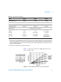
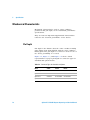
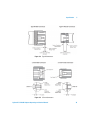
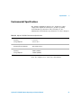
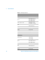
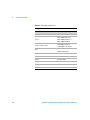
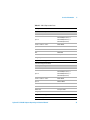
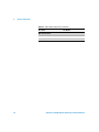
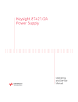
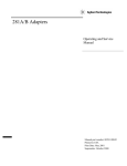
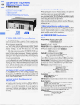
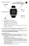
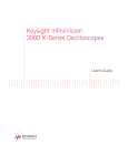
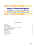
Agilent X/P/K281C
Adapters
Including Options 006, 012,
013, 106
Operating and Service
Manual
Contents
1
Introduction
7
Product Overview 8
Options 8
Instruments Covered by Manual
2
Installation
11
Initial Inspection
12
Operation and Safety Precautions
Operating Procedure 13
Performance Test – SWR 14
Adjustments 14
3
Specification
10
13
15
General Specifications 16
Physical Specifications 16
Specifications 16
Mechanical Characteristic
Pin Depth 18
18
Environmental Specifications
Safety and Regulatory Markings
Declaration of Conformity
4
Service Information
21
22
24
25
Service Information 26
Replacing the Center Conductor Contact
Replaceable Parts
26
27
Agilent X/P/K281C Adapters Operating and Service Manual
5
This page is intentionally left blank.
6
Agilent X/P/K281C Adapters Operating and Service Manual
Agilent X/P/K281C Adapters
Operating and Service Manual
1
Introduction
Product Overview 8
“Options” on page 8
“Instruments Covered by Manual” on page 10
This chapter provides an overview of the Agilent X/P/K281C
Adapters.
1
Introduction
Product Overview
The X281C, P281C, and K281C adapters provide a
convenient means of coupling between waveguide and
coaxial systems. Power can be transmitted in either
direction, and each adapter covers the full frequency range
of its waveguide size. A step- like internal structure
transforms the waveguide impedance to the 50 Ω impedance
of the coaxial line.
Options
Option 006
Option 006 adds two alignment holes to the waveguide
flange. The dimensions of the Option 006 alignment holes
are provided in the following table.
Table 1-1 Option 006 Alignment Hole Measurement Dimensions
8
Model
Alignment Hole
Diameter “A”
Dimension “B”
Dimension “C”
X281C
3.175 mm
(+0.014 to 0.0)
15.49 mm
16.26 mm
P281C
3.175 mm
(+0.014 to 0.0)
12.62 mm
12.14 mm
K281C
2.381 mm
(+0.014 to 0.0)
8.13 mm
8.51 mm
Agilent X/P/K281C Adapters Operating and Service Manual
Introduction
1
Figure 1-1 K281C Option 006 Waveguide Alignment Holes
Option 012
Option 012 for the X281C offers a Type- N (m) connector to
replace the standard 7- mm connector.
Option 012 for the K281C offers a 3.5 mm (m) connector to
replace the standard 3.5 mm (f) connector.
Option 013
Option 013 for the X281C offers a Type- N (f) connector to
replace the standard 7- mm connector. Option 013 is not
offered for the K281C and the P281C.
Option 106
Option 106 is only available for the K281C. It replaces the
standard 3.5 mm (f) connector with a 3.5 mm (m) connector
and adds two alignment holes to the waveguide flange. The
dimensions of the alignment holes are identical to Option
006 for the K281C as shown in Table 1- 1.
Agilent X/P/K281C Adapters Operating and Service Manual
9
1
Introduction
Instruments Covered by Manual
The adapters covered by this manual have a two part serial
number. The first four digits and letter constitute the serial
number prefix. The last five digits form the sequential suffix
that is unique to each adapter. The contents of this manual
apply to adapters prefixed at 3032A and above.
10
Agilent X/P/K281C Adapters Operating and Service Manual
Agilent X/P/K281C Adapters
Operating and Service Manual
2
Installation
Initial Inspection 12
Operation and Safety Precautions 13
“Operating Procedure” on page 13
“Performance Test – SWR” on page 14
“Adjustments” on page 14
This chapter provides you important information on how to
check and prepare your instrument for operation.
2
Installation
Initial Inspection
Unpack and inspect the shipping container and its
contents thoroughly to ensure that nothing was damaged
during shipment. If the shipping container or cushioning
material is damaged, the contents should be checked both
mechanically and electrically. Check for mechanical
damage such as scratches or dents.
12
Agilent X/P/K281C Adapters Operating and Service Manual
Installation
2
Operation and Safety Precautions
Observe the following guidelines before connecting or
operating the adapter.
CAUTION
• Exceeding the allowable energy and power levels may result in
damage to the adapter or associated equipment.
• Care should be taken to protect the face of the flange from any
damage that would prevent close surface-to-surface contact. Any
burring, denting, or scratching may increase RF leakage and the
reflection coefficient of the waveguide connection. The supplied
plastic cover should be used to protect the flange when the adapter
is not in use.
• The power that can be handled will be a function of the size of the
center conductor. The majority of the heat flow will be via
conduction. The weak point is the coax portion. The waveguide
portion is capable of higher power. These numbers are assuming an
ambient temperature of 25 °C and an altitude of sea level. Higher
ambient temperatures and altitude would degrade power-handling
capability.
Operating Procedure
Use the following procedure when you connect an adapter to
a waveguide.
1 Make sure the rectangular ports are oriented the same
way; that is, not “cross- guided”.
2 Align ports carefully to minimize reflections.
3 Clamp or bolt flanges securely together so that pressure is
evenly distributed over the contacting surfaces. Loose
waveguide connections and flange distortion may result in
leakage and mismatch.
Agilent X/P/K281C Adapters Operating and Service Manual
13
2
Installation
Performance Test – SWR
The maximum SWR for the adapters are shown in Table 3- 1
and Figure 3- 1. When making these measurements, the test
results must be less that those listed in Table 3- 1 plus the
measurement uncertainty of the measuring system.
Measurements may be made using a standard reflectometer
setup. To ensure satisfactory performance, make sure flanges
and coaxial connectors are not damaged or worn.
Adjustments
Adjustments should not be made unless the adapter does not
meet specifications, or unless the unit has been physically
damaged.
14
Agilent X/P/K281C Adapters Operating and Service Manual
Agilent X/P/K281C Adapters
Operating and Service Manual
3
Specification
General Specifications 16
“Physical Specifications” on page 16
“Specifications” on page 16
Mechanical Characteristic 18
“Pin Depth” on page 18
Environmental Specifications 21
Safety and Regulatory Markings 22
Declaration of Conformity 24
This chapter provides the specifications of the Agilent
X/P/K281C Adapters.
3
Specification
General Specifications
Physical Specifications
Model
X281C
P281C
K281C
Net weight
210 g (7.20 oz)
110 g (4.0 oz)
40 g (1.3 oz)
Length
73 mm (2.9 in)
52 mm (2.0 in)
35 mm (1.4 in)
Width
41 mm (1.6 in)
33 mm (1.3 in)
22 mm (0.9 in)
Height
61 mm (2.4 in)
55 mm (2.2 in)
38 mm (1.5 in)
Dimensions:
Waveguide size:
Nominal outer
diameter
25.40 x 12.70 (mm) 17.83 x 9.93 (mm)
12.70 x 6.35 (mm)
1.00 x 0.50 (in)
0.50 x 0.25 (in)
0.70 x 0.39 (in)
Specifications
Specifications refer to the performance standards or limits
against which the adapter is tested.
Typical characteristics are included for additional
information only and they are not specifications. These are
denoted as “typical”, “nominal”, or “approximate” and are
printed in italic.
Table 3-1 Specifications
Model
X281C
P281C
K281C
8.2 to 12.4
12.4 to 18
18 to 26.5
SWR*
< 1.05
< 1.06
< 1.07
(Typical SWR)
(< 1.03)
(< 1.04)
(< 1.05)
0 to +55 °C
0 to +55 °C
0 to +55 °C
Frequency range (GHz)
Operating temperature
16
Agilent X/P/K281C Adapters Operating and Service Manual
Specification
3
Table 3-1 Specifications (continued)
Model
X281C
P281C
K281C
0.08 dB
0.10 dB
0.12 dB
Maximum peak power
200 W
200 W
100 W
EIA
WR90
WR62
WR42
UG-135/U
UG-419/U
UG-597/U
Typical insertion loss
†
Equivalent flange type
4 holes (6 holes for option 006‡)
Alignment holes
Connector type:
7-mm
7-mm
3.5 mm female
N-male
Not available
3.5 mm male
Option 013
N-female
Not available
Not available
Option 106
Not available
Not available
3.5 mm male with 6
alignment holes
Standard
Option 012
* Specifications in this table are measured with no gap between the full diameters of the male and female center conductors.
† The power that can be handled will be a function of the size of the center conductor. The majority of the heat flow will be via
conduction. The weak point is the coax portion. The waveguide portion is capable of higher power. These numbers are assuming an ambient temperature of 25 °C and an altitude of sea level. Higher ambient temperatures and altitude would degrade power-handling capability.
‡ Option 006 is only available for the standard connector type.
Figure 3- 1 shows the variation in SWR introduced by the
center conductor gap.
Figure 3-1 Typical SWR Variation Versus Center Conductor Gap
Agilent X/P/K281C Adapters Operating and Service Manual
17
3
Specification
Mechanical Characteristic
Mechanical characteristics, such as center conductor
protrusion and pin depth, are not warranted performance
specifications.
They are however important supplemental characteristics
related to the electrical performance of the devices.
Pin Depth
Pin depth is the distance that the center conductor mating
plane differs from being flushed with the outer conductor
mating plane. The pin depth of a connector can be in one of
two states, protruding or recessed.
Figure 3- 2, Figure 3- 3, and Figure 3- 4 show a visual
representation of proper pin depth for connector types for
standard and option models.
Table 3-2 Connector Types for Standard and Options
Model
X281C
Standard/Option 006 7-mm
18
P281C
K281C
7-mm
3.5 mm female
Option 012
N-male
Not available
3.5 mm male
Option 013
N-female
Not available
Not available
Option 106
Not available
Not available
3.5 mm male
Agilent X/P/K281C Adapters Operating and Service Manual
Specification
3
Figure 3-2 Type-N Connectors
Figure 3-3 3.5-mm Connectors
Agilent X/P/K281C Adapters Operating and Service Manual
19
3
Specification
Figure 3-4 7-mm Connector
20
Agilent X/P/K281C Adapters Operating and Service Manual
Specification
3
Environmental Specifications
The Agilent X/P/K281C adapters are designed to fully
comply with Agilent Technologies’s product operating
environmental specifications. The following are the
summarized environmental specifications for these adapters.
Table 3-3 Agilent X/P/K281C Environmental Specifications
Temperature
• Operating
0 °C to 55 °C
• Storage/Shipment
–55 °C to 75 °C
Relative Humidity
• Operating/Storage/Shipment
<95% relative at 40 °C
Altitude
• Operating
<4600 m (15000 ft)
• Storage/Shipment
<15000 m (50000 ft)
Store the adapters in a clean, dry environment.
Agilent X/P/K281C Adapters Operating and Service Manual
21
3
Specification
Safety and Regulatory Markings
This symbol indicates that you should refer to the instrument’s
instruction manual for important information.
This symbol indicates hazardous voltages.
The laser radiation symbol is marked on products that have a
laser output.
This symbol indicates that the instrument requires alternating
current (ac) input.
The CE mark is a registered trademark of the European
Community. If it is accompanied by a year, it indicates the year
the design was proven.
ff
N10149
The C-Tick mark is a registered trademark of the Australian
Spectrum Agency.
The CSA mark is a registered trademark of the Canadian
Standards Association.
ISM1-A
This text indicates that the instrument is an Industrial Scientific
and Medical Group 1 Class A product (CISPER 11, Clause 4).
This ISM device complies with Canadian ICES-001.
Cet appareil ISM est conforme a la norme NMB du Canada
This symbol indicates that the power line switch is ON.
22
Agilent X/P/K281C Adapters Operating and Service Manual
Specification
3
This symbol indicates that the power line switch is OFF or in
STANDBY position.
Agilent X/P/K281C Adapters Operating and Service Manual
23
3
Specification
Declaration of Conformity
A copy of the Manufacturer’s Declaration of Conformity for
this instrument can be obtained by contacting your local
Agilent Technologies sales representative.
24
Agilent X/P/K281C Adapters Operating and Service Manual
Agilent X/P/K281C Adapters
Operating and Service Manual
4
Service Information
Service Information 26
“Replacing the Center Conductor Contact” on page 26
Replaceable Parts 27
This chapter provides service instructions and lists the
available replaceable parts for the Agilent X/P/K281C
Adapters.
4
Service Information
Service Information
Replacing the Center Conductor Contact
Not all parts on the adapters are replaceable, but all of the
adapters have a replaceable center conductor contact.
When you replace the center conductor contact, observe the
following precautions:
• Before installing the new center conductor contact, apply
Loctite sealant #222 to the threads of the center
conductor.
• Do not use excessive force when tightening center
conductor parts.
Model K281C (All Options)
To replace the center conductor, you will need a 5/64 inch
hexagonal nut driver.
In some units, the center conductor mounting hole was
made oversized to allow for a slight adjustment. When the
center conductor is replaced in these units, it may be
necessary to readjust and retest if the unit does not meet
specifications.
If the mounting hole appears to be oversized, mount the
center conductor toward one end of the adapter as far as it
will go. If the adapter fails the performance test, move the
center conductor toward the opposite end and then retest.
26
Agilent X/P/K281C Adapters Operating and Service Manual
Service Information
4
Replaceable Parts
Replaceable parts for the P281C adapter are shown below.
Refer to Table 4- 1, Table 4- 2, and Table 4- 3 for
identification of parts and corresponding part numbers for
all models. For ordering information, contact the nearest
Agilent office listed in “Contacting Agilent” in the front
matter of this manual.
Figure 4-1 Replaceable Parts
NOTE
CAUTION
Table 1-1 on page 8 gives dimensional tolerances for Option 006 that can
be expected to yield satisfactory results. It may be necessary to try various
combinations of spacers and shims to obtain proper dimensions. The use
of at least one shim is recommended because of electro-chemical
differences between the connector body and the adapter body. Refer to the
appropriate table of replaceable parts for the thickness of shims and
spacers.
Take care to avoid damaging parts. Burring, scratching, denting, or
deforming parts may impair operating characteristics.
Agilent X/P/K281C Adapters Operating and Service Manual
27
4
Service Information
Table 4-1 X281C Replaceable Parts
Description
Part Number
X281C Standard/Option 006
Connector body
1250-1466
00281-20027 (0.05 mm), or
Spacer
00281-20028 (0.075 mm), or
00281-20049 (0.025 mm)
Center conductor contact
85050-20001 (G-slotted)
85130-20002 (collet holder)
5020-8540 (0.013 mm), or
Shim
5020-8541 (0.025 mm)
Center conductor
Not replaceable
Spacer
Not replaceable
Washer
Not replaceable
Nut
Not replaceable
Blank label
Not replaceable
Flange cap
5040-0354
X281C Option 012
1250-0916 (Male)
Connector body
1250-0918 (Nut)
1250-0016 (Ring)
00281-20027 (0.05 mm), or
Spacer
00281-20028 (0.075 mm), or
00281-20049 (0.025 mm)
Center conductor contact
5020-8540 (0.013 mm), or
Shim
28
5180-0988
5020-8541 (0.025 mm)
Center conductor
Not replaceable
Spacer
Not replaceable
Agilent X/P/K281C Adapters Operating and Service Manual
Service Information
4
Table 4-1 X281C Replaceable Parts (continued)
Description
Part Number
Washer
Not replaceable
Nut
Not replaceable
Blank label
Not replaceable
Flange cap
5040-0354
X281C Option 013
Connector body
1250-0914
00281-20027 (0.05 mm), or
Spacer
00281-20028 (0.075 mm), or
00281-20049 (0.025 mm)
Center conductor contact
Shim
5180-0854
5020-8540 (0.013 mm), or
5020-8541 (0.025 mm)
Center conductor
Not replaceable
Spacer
Not replaceable
Washer
Not replaceable
Nut
Not replaceable
Blank label
Not replaceable
Flange cap
5040-0354
Agilent X/P/K281C Adapters Operating and Service Manual
29
4
Service Information
Table 4-2 P281C Replaceable Parts
Description
Part Number
P281C Standard/Option 006
Connector body
1250-1466
00281-20027 (0.05 mm), or
Spacer
00281-20028 (0.075 mm), or
00281-20049 (0.025 mm)
Center conductor contact
85130-20002 (collet holder)
5020-8540 (0.013 mm), or
Shim
30
85050-20001 (G-slotted)
5020-8541 (0.025 mm)
Center conductor
Not replaceable
Spacer
Not replaceable
Washer
Not replaceable
Nut
Not replaceable
Blank label
Not replaceable
Flange cap
5040-0358
Agilent X/P/K281C Adapters Operating and Service Manual
Service Information
4
Table 4-3 K281C Replaceable Parts
Description
Part Number
K281C Standard/Option 006
Connector body
1250-1507
5021-9679 (0.013 mm), or
Spacer
5021-9680 (0.025 mm), or
5021-9681 (0.051 mm)
Center conductor contact
00281-20043
Spacer
000281-20045
Washer
3050-0261
Nut
0608-0003
Blank label
Not replaceable
Flange cap
5040-0357
Required but not Supplied
5/64 inch hexagonal nut driver
K281C Option 012/Option 106
Connector body
1250-1509
5021-9679 (0.013 mm), or
Spacer
5021-9680 (0.025 mm), or
5021-9681 (0.051 mm)
Center conductor contact
00281-20044
Spacer
000281-20045
Washer
3050-0261
Nut
0608-0003
Blank label
Not replaceable
Flange cap
5040-0357
Required but not Supplied
5/64 inch hexagonal nut driver
Agilent X/P/K281C Adapters Operating and Service Manual
31
4
Service Information
Table 4-3 K281C Replaceable Parts (continued)
Description
Part Number
Miscellaneous Items
32
Loctite #222
0470-0573
Operating and Service Manual
00281-90043
Agilent X/P/K281C Adapters Operating and Service Manual