1
o
Oo
X
70
»V Æ
i
\A + l
fe'*.
*;-",
.--rjLi: ^{Cfc-fLi X"'
ÏJ1 --
fe
I SCfc*
»HtfcM»
•
^3T'"
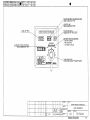
»3 DESIGN DEPT 2
** "?™**f £L
r
• *1S30
F" * •
Y
- 4
^
{
S HAN
C- K. LEE
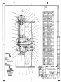
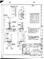
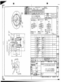
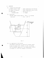
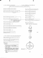
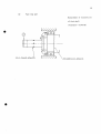
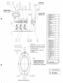
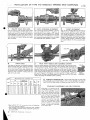
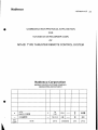
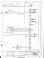
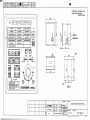
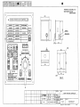
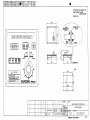
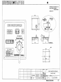
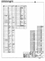
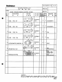
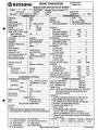
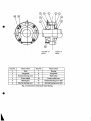
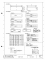
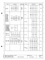
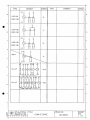
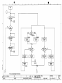
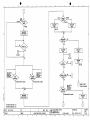
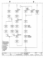
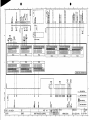
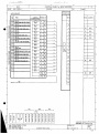
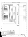
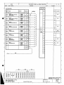
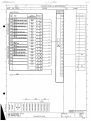
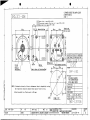
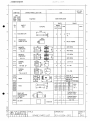
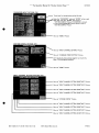
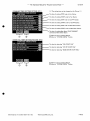
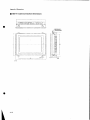
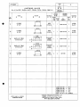
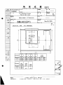
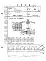
SHIP TYPE
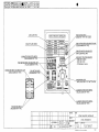
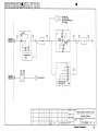
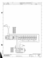
4,150 TEU CLASS CONTAINER CARRIER
SHIP NAME
MAERSK GREENOCK (IMO 9298686)
NAME OF DRAWING
TUNNEL THRUSTER (1/2)
Î
»Vi'1* "
^ E B 13.13
ft BSXISTRIES CO.,LTD
*ÊmX KOREA
SCALE
DRAWING NO.
/
CONSOLIDATED NO.
6 J-7116-001
lQ _ 8
IMO 9298686
HHI 1630
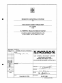
KAWA5AKI
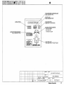
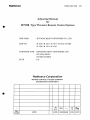
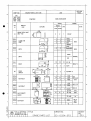
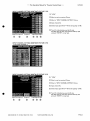
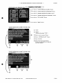
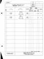
Vessel's Name " MAERSK GREENOCK "
HYUNDAI HEAVY INDUSTRIES CO..LTD.
S.NO.H1630
KAWASAKI SIDE THRUSTER
KT-157B3TYPE
FINISHED PLAN
DELIVERY
( YARD
5
.^*T7c &\/Y IMn77S>^
Sv&Q*^
—~^??ç>\.
/^MACHINERY D I V ^ N
'(
HOV 14 2005 ) • )
RINE MACI-HINERY y
DEPT.
/
KPMEIfg
KPMEX^ 1
m &
få
ISSUE
1
KAWAEaAKI
H E A V Y I N D U S T R I E S , LTD.
MACHINERY DIVISION
MARINE MACHINERY DEPARTMENT
[ ORDER NO. 31KB068 ]
À
^ ^ ^ ^ ^ ^ f l
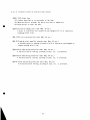
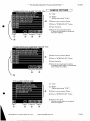
SIDE
1.
THRUSTER
TYPE
• KT-157B3
2. MACHINE NO.
• 3426
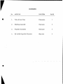
CONTENTS
1. TECHNICAL SPECIFICATION & DRAWINGS
2. TECHNICAL DATA
3. INSTRUCTION BOOK
4. REMOTE CONTROL SYSTEM
5. MAIN MOTOR
6. STARTER PANEL
7. SPARE PARTS & SPECIAL TOOLS
8. TEST AND INSPECTION REPORT
0
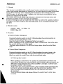
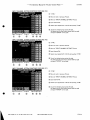
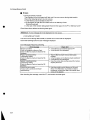
KAWASAKI
TECHNICAL SPECIFICATION & DRAWINGS
OF
KAWASAKI SIDE THRUSTER
KT-157B3
FOR
4,150TEU Class Container Carrier
HYUNDAI HEAVY INDUSTRIES CO..LTD.
S.NO.H1630/1,1671/2,1699-1701,1733
DELIVERY
YARD
ORDER NO.
31KB068 ,70,72,74,76,78,80,82
NOTES
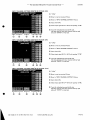
1<AWASAKE
YHEAVY INDUSTRIES, LTD.
GAS TURBINE & MACHINERY COMPANY
MACHINERY DIVISION
MARINE MACHINERY DEPT.
PROPULSION MACHINERY ENG'NG SECT.
KPMEI3S
KPMEZ*
REVISION
I»
mtL
/
APP ROVED
a
CHECKED
1
DRAWN
ISSUE
DATE
—•"7>=> / 1
f//7S
'
>i
DRAWING NO.
November 24, 2004
G4-001-254 Rl
(
SHEETS COVER INC)
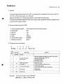
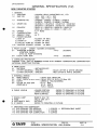
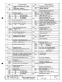
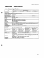
I. General
1. Customer
2. Ship Owner
3. Shipyard
4.
5.
6.
7.
8.
Kind of ship
Hull dimension
Ship speed (Service)
Classification
Installation position
HYUNDAI HEAVY INDUSTRIES CO..LTD.
AP.Moller
HYUNDAI HEAVY INDUSTRIES CO..LTD.
S.No.H1630/1,1671/2,1699-1701,1733
4.150TEU Container Carrier
Lpp x B x D x d = 277 x 32.25 x 21.7 x 12.2 m
abt. 24.5 kt.
LR
Bow
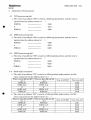
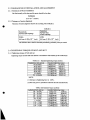
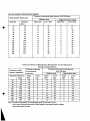
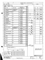
II. Particulars
1. Thruster unit
Type
KT - 157B3 Controllable Pitch type with motor base
Number of units
1 unit/vessel
Propeller diameter
2200 mm ( skewed type ) x 4 blades
Thrust
abt. 196 kN {abt. 20.0 ton}
Propeller speed
315 r/min
Input shaft speed
1160 r/min
Input power
1335 kW
Direction of input shaft rotation
Counter clockwise view from prime mover
Position of propeller blade
Port side
2. Prime mover and control device
2-1 Main motor
Type
: 3 phase, totally enclosed, vertical type
squirrel cage induction motor (IP44)
Number of units
: 1 unit/vessel
Output
1335 kW
Revolution number
Voltage x Frequency
Rating
Rating Current
Insulation
Starting method
Accessories
1200 r/min (synchronous speed)
AC 3 0 3,300 V 60 Hz
30 min.
abt. 284 Amp
F class
Auto transformer with 50 % tap
-One (1) set, space heater, element type
AC 220V x 60 Hz x 400 W x 1ph
-One (1) set, temperature sensor, Pt100, for each phase
Notice: Monitoring system to be supplied by Shipyard.
-Two(2) sets, PTC thermisters with relays for high temperature
alarm & trip to be installed in the starter.
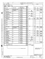
2-2 Motor control device
Type
Number of units
self-standing type starter(IP44)
1 units/vessel;
including, hyd. pump motor starter
-1 -
Power source
Accessory
3. Hydraulic unit
3-1 Oil service pump
3-2 Accessory/unit
3-3 Driving motor
Type
AC
AC
AC
AC
30
30
30
30
3,300 V 60 Hz for power source of thruster motor,
220 V 60 Hz for control (transformed in starter),
220 V 60 Hz for space heater(transformed in starter),
440 V 60 Hz for power source of hyd. pump motor
1) Local control box(IP56)
2) Emergency stop button for main motor
Floor mounting type x
1 unit/vessel
Vertical screw type x 1 set/unit
41.4 lit/min x 4.5 MPa {46 kgf/cm2} x 3500 r/min
DC solenoid valve (1), Pressure switch (2), Safety valve (1),
Suction filter (1)
4. Flexible coupling
Totally enclosed induction motor (IP44) x 1 set/unit
AC 3 0 440 V 60 Hz 5.5 kW x 3600 r/min(sync speed)
with space heater(winding type, 15Vx2.6A x 1ph)
SF coupling 1130T-10 x 1 set/vessel
5. Gravity tank
including a mating coupling for main motor
Cylindrical wall mounting type x 1 unit/vessel
including level switch (1set, 2 contacts), Level gauge (1)
Volume : 80 Lit.
6. Remote control system
Type
Control position
Wheel house
Wings
Additional circuit
Power supply
7. Mass per unit
Thruster unit (dry)
Prime mover
Thruster starter
Hydraulic unit
Flexible coupling
Gravity tank (dry)
Accessory
Electric-hydraulic, follow-up control type
Master control device x 1 set/vessel
Flush panel mounting type
Wing control device x 2 sets/vessel
Flush panel mounting type (IP56)
Over Load P rotf ;tion device
AC 1 0 220 V 60 Hz
DC 24 V as bback up source for indicating system
abt.
abt.
abt.
abt.
abt.
abt.
abt.
8600 kg
5800 kg
1700 kg
260 kg
91 kg
80 kg
50 kg
-2-
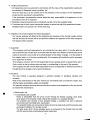
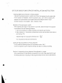
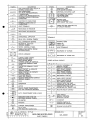
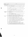
I. Testing and Inspection
1. All inspections are to be executed in accordance with the rules of the classification society and
the standard of Kawasaki Heavy Industries, Ltd.
Only the shop test is to be carried out in the presence of the surveyor of the classification
society and the purchaser's representative.
If the purchaser's representative cannot attend the test, responsibility of acceptance is to be
entrusted to the K.H.Ps inspector.
2. Statically momental balance test is individually carried out for the propeller blade.
3. Functional test of pitch control mechanical system is carried out with fully assembled thruster.
Rotational test is not carried out in KHI's work shop.
IV. Dispatch of a service engineer for technical guidance
Our service engineer will attend at the adjusting and checking of the thruster system before
sea trial and also at the sea trial as a supervisor subject to the payment of the extra charge by
the shipyard when required.
V. Guarantee
This company hold itself responsible for any trouble that has risen within 12 months after the
ship is delivered but not later than 18 months after the date of the delivery of the thruster to the
customer and when such trouble is found attributable to the defect in design, or to the defect of
the material used, or to the poor workmanship, this company will provide the parts necessary
for a repair free of charge.
This company, however, will not hold responsible for any damage which is caused by the act of
God or which is due to ordinary tear and wear, or mishandling on the part of the operator.
This company also will not hold itself responsible for any consequential or indirect loss which is
brought about by damage of any nature whatsoever.
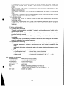
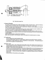
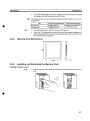
VI. Structure
The side thruster is specially designed in sufficient strength to withstand vibration and
corrosion.
Most of the mechanisms for the pitch control are conveniently laid out inside the vessel, thus
offering higher accessibility, safety and reliability.
The specially designed structure also permits easy overhaul and reassembly of the unit as well
as trouble-free maintenance.
1. Side thruster unit
1-1 Controllable pitch propeller
Power is transmitted from the prime mover through the flexible coupling, input shaft,
bevel gears to the propeller shaft, rotating the propeller in a constant direction.
The propeller part consists of four propeller blades, a propeller hub with a hydraulic
servomotor and the sliding block mechanism.
The propeller blades are connected to blade carriers by blade bolts and this assures easy
exchange of blades in the thruster tunnel.
The gear case, which carries propeller parts, is connected to the thruster tube by bolts
and this assures easy overhauling all parts inside tube.
-3-
Pressurized oil from the solenoid valve is fed to the hydraulic servomotor through the
pipes in the propeller shaft, resulting in the reciprocal movement of the servomotor
piston.
This movement of the piston is converted into rotary movement of the blades by the
sliding block mechanism.
Shaft sealing mechanism, which is attached to the gear case, is adopted for the propeller
shaft.
The propeller blades are carefully designed with proper area and thickness to have
sufficient strength and to withstand cavitation.
1-2 Lubricating device
The bevel gear and all the bearings inside the gear case are lubricated by the bath
lubricating method.
Furthermore, the lubrication oil in the gear case is slightly pressurized by the connection
with the gravity tank which is provided above the water surface to prevent sea water from
leaking in.
2. Remote control system
2-1 Propeller pitch controlling
The pitch controlling device consist of a hydraulic unit(including solenoid valve) and a
remote control device.
The control system is of the electric remote control type and a master control panel is
provided for bridge console.
The system is so designed that the Follow-up control by a control dial on the control panel
is possible.
The propeller pitch is automatically controlled to reduce the pitch sensing the load of main
motor for protection from overload operation.
2-2 Remote motor controlling
1) One set operation switch is provided on the master control panel so that starting of ail
necessary equipment, such as oil service pump and main motor, is made from the
bridge.
Stopping of all thruster equipment is made by the same switch from the master control
panel.
2) Following contacts are provided for the prime mover start interlock
a) Gravity tank oil level
Normal close, open at low level
b) Control oil pressure
Normal close, open at low pressure
c) Blade angle
Close at pitch neutral zone ( AB : +3°
3°
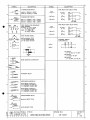
VII. Materials for main parts
Propeller blades
: Ni-Aluminium bronze casting
Propeller hub
: High strength brass casting
Propeller shaft
: Carbon steel forging
Spiral bevel wheel
: Alloy steel
Input shaft
: Alloy steel
Tube
: Rolled steel plate specified by the Rule and
stainless steel (SUS316) in way of propeller tip
Gear case
: Ductile iron casting
-4-
VIII. Extent of supply
^
9
1. Side thruster unit (including companion flanges for piping)
1 set / vessel
Anodes to be provided and fitted by Shipyard.
2. Flexible coupling
1 set / vessel
3. Hydraulic unit
1 unit / vessel
4. Gravity tank with level switch
1 set / vessel
5. Hand pump
1 pc / vessel
6. Main motor
1 set / vessel
7. Oil service pump motor
1 set / vessel
8. Motor control device(including control circuit of the pump motor)
1 set / vessel
9. Remote control system
The following parts are individually supplied by K.H.I, and assembled on bridge console
by Shipyard.
A) Master control panel provided with following parts
1 set / vessel
Type
: Flush panel mounting, printed text type
Q'ty/panel
a) Operation
1) Follow-up pitch control dial with lever ±
1 set
2) Non follow-up control button (Port - Stbd)
1 set
3) Operation switch with indication
1 set
- Cont. power OFF : Power & System OFF
- Cont. power ON : Power & System ON (With Indication lamp)
- Pump Stop
: Hyd. oil pump's motor and fan's motor stop
- Pump Run
: Hyd. oil pump's motor and fan's motor run
- Thruster Stop
: Stop main motor
- Thruster Run
: Start main motor
4) Control mode change-over switch and indication
1 set
- Non follow up
: Non follow up control mode
- Follow up
: Follow up control mode
5) Pitch control position change-over switch and indication
1 set
- W/H
: Wheel house control
- Wing
: Wing control
6) Panel control switch
1 set
- Dark and bright : Control panel illumination
- Lamp buzzer test
- Buzzer stop
7) Emergency stop button
1 set
8) Thruster Request (equal to Power Request) push button
1 set
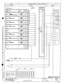
b) Indicator
- Pitch indicator with LED lighting
- Load indicator (Percentage indication)
-5-
1 set
c) Indication lamps Zn
6
1) Main source ON (3300V)
2) Hyd oil pump source ON
3) Power available
4) Main motor full load
5) Ready to start
6) Bow th. room fan run
d) Alarm lamp
12
1) AC source failure
2) DC source failure
3) Controller abnormal
4) Low oil level (at the gravity tank)
5) Low pressure (at the hydraulic syste)
6) Oil service pump overload
7) Main motor overload
8) Main motor trip
9) Main motor high temperature
10) Main motor Insulation low
11) Auto pitch reduct. (at main motor trip and generator overload)
/ i ^ 12) Bow th room Fal fail
B) Terminal board unit
1 set / vessel
- Type: Open chassis type, to be installed in the bridge console by Shipyard.
- Accessory: 2 meter length flat cable, to connect with master control panel.
C) Wing control panel (IP56)
- Type
: Flush mounting type
- Provision
;
1) Follow-up pitch control dial with lever ^
2) Pitch indicator
3) Pitch control position change over confirm, button
4) System abnormal alarm lamp
5) Integrated alarm lamp
6) Main motor emergency stop button
7) Alarm buzzer
8) Buzzer stop button
9) Lamp & buzzer test button
10) Dimmer switch for lamps and indicators
2 sets / vessel
Q'ty/box
1
1
1
1
1
1
1
1
1
1 set
D) Pitch transmitter with blade angle scale, mounted on the thruster unit
1 set / vessel
E) Signal supply to VDR
1) Pitch order signal (PORT 25°
1 set / vessel
~ STB'D 25° )
1
(Through RS-422 serial communication)
2) Actual pitch signal (PORT 25°
~ STB'D 25° )
(Through RS-422 serial communication)
-6-
1
10. Spare parts and tools
1) Packings and O-rings
2) Tools and parts for electric system
3) Special tools
each kind of one unit
IX. Coating and color / i \
LTube
A) Surface exposed to sea water
(BROWN)
1)ENA 300/303
150//
2)FAJ 034/262
(GREY)
75//
3)BEA 464
(DARK RED)
150 //
4)BEA 465
(BROWN)
150//
5)BEA 464
(DARK RED)
150/i
B) Other part
a) Ground coating
(GRAY)
15//
NIPPE CERAMO
b) Finishing
To be finished by the shipyard with the same paint used
1 set/vessel
1 set/vessel
1 set/vessel
x1
x1
x1
x1
x1
x1
on the hull surface.
2. Other machinery ^A
A) Hydraulic unit, flexible coupling and Spare & tools box
40 u x 2
a) Ground coating LZ PRIMER M
(ORANGE)
(Munnsel No.7.5Y 9/6)
25 // x 2
b) Finishing
UNIPACK 200
B) gravity tank
(GRAY)
100// x 1
a) Ground coating LZ PRIMER M
UNIPACK
200
(Munnsel No.Gray N8.0) 100// x 1
b) Finishing
C) Electrical equipment for thruster room
a) Ground coating
Manufacturer's standard
2 times
b) Finishing
Manufacturer's standard
2 times
Color
Munnsel No. 10 GY 8/4 ( For Main Motor)
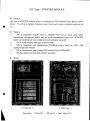
Munnsel No. N 7.5
( For Starter Panel)
D) Electrical equipment for bridge
a) Ground coating Manufacturer's standard
2 times
b) Finishing
Manufacturer's standard
2 times
Color
Manufacturer's standard
Munnsel No. N-2.0 (master panel & wing panel)
-7-
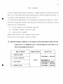
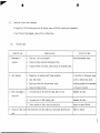
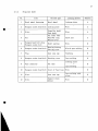
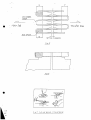
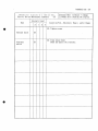
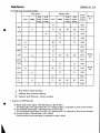
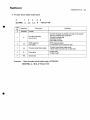
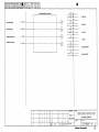
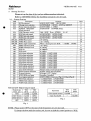
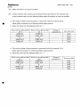
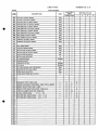
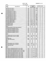
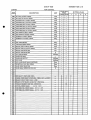
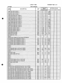
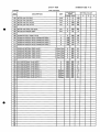
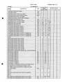
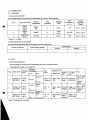
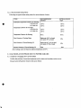
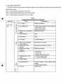
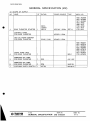
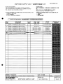
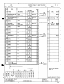
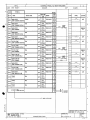
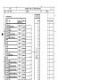
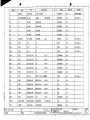
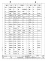
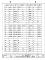
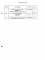
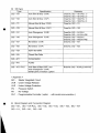
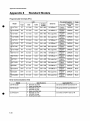
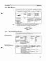
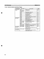
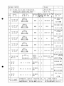
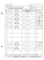
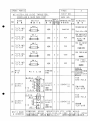
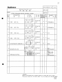
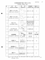
X. Drawings for submission
Name of documents
Technical spec. &. drawings for thruster
Remote control system
Main motor
Starter panel
Shop test procedure
Approval
spec.
For
Working
Finished
plan
15
15
8
8
5
15
8
5
15
8
—
5
—
1*
—
5
15
15
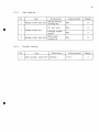
Spare parts & special tools
Instruction book
—
Results oftest & inspection
5
5
5
—
* Reproducible sheet
XI. Exception of supply
The followings are not included in our supply.
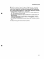
1. Bellmouth and nozzle which are joined to the thruster tube.
2. Fitting of the tube to the hull structure.
3. Guard grids (to be provided by the shipyard).
4. Anti-corrosive anodes for tunnel, bellmouth, guard grids, nozzle and adjacent section.
5. Materials for the piping and piping fittings.
6. Materials for the wiring and wiring fittings.
7. Installation of the gravity tank and the hydraulic unit.
8. Installation bases, bolts and nuts for motor control device.
9. Installation of electric equipment (Control panel, stand, motor and so on).
10. Supports for main motor to protect from vibration.
11. Lubricating oil (Gear oil ISO VG 100, 670 liter).
12. Parts for bridge control system
13. Step up transformer
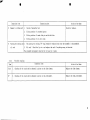
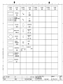
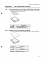
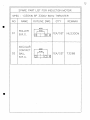
XII. Recommended oil and grease for thruster
Oil maker
Gear oil
Grease
NIPPON OIL
BONNOC SP 100
EPNOC GREASE AP2
IDEMITSU KOSAN CO.LTD.
Daphne Super Gear Oil 100
Daphne Coronex Grease EP2
MITSUBISHI
DIAMOND GEARLUB SP 100
DIAMOND MULTIPURPOSE EP2
Japan Energy Corporation
JOMO Reductus 100
JOMO Lisonix Grease EP2
SHELL
OMALA OIL 100
ALVANIA EP2
ESSO
SPARTAN EP 100
LITHTAN EP2
MOBIL
MOBIL GEAR 627
MOBILUX EP
FRANCE PETROLEUM
TOTAL CARTER EP 100
TOTAL MALTIS EP 2
TEXACO
MEROPA 100
PREMIUM RB GREASE2
Castrol Limited
ALPHA SP 100
SPHEEROL AP2
-8-
V
39
9
fi-y
CHAIN
UolBftaas
! _ _
|AL-ANODE
I -~|
i _ i _
^^^^^^^^^^^^^^^^^^^^^^^^^^^^^^^^^^^^^^^^ u_ï
\
x
l U t l l l H T tlfllioa I ~ " " T ~ ™
1 O i«iit «ciiitrr K f i , „ . . „ ,
T m
AyiBfe
1»«;''
I OVNER M l
ODDER NO. M
RO LEU
I
w
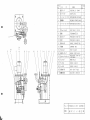
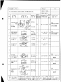
" KT-32B ~ 355B3
«JST
ClEtlED
\i&
• •
scÂu
THRUSTER
ÏRTUT
W
»»^fclri^-|r» °A
KAWASAKI
ASSEMBLY
777^fflUKIB
HEAVY
G4-2O1-282
INDUSTRIES.
LTD.
iB 8 H
|""|
KOBE JAPAN
(A36)
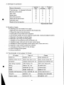
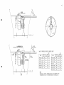
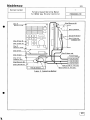
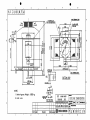
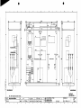
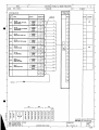
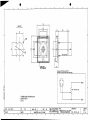
2. î f » t © » ± t f l l ( « 5 8 0 0 k g ) CJtU»*«CÄBÄft±IT
4. igwscHsmaa© r i8i*ci>tfsai*«j t & r ^ T T ê u
=
.Vuïlïiïv
T m w
*'
i_s
«_1
KT-157B3
*•"
U t IL P.
|T|
tt
H ' i/ao
k.
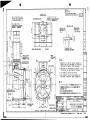
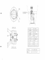
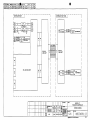
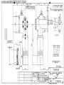
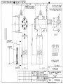
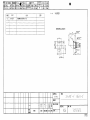
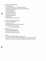
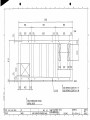
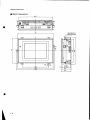
INSTALLATION OF SIDE THRUSTER
ffrl
pB.gRfa ^ | p ^ L i l | » ; - »'•
*
s8
VJVZ729 iMSJB
R4 - 3 0 0 - 3 3 9
KAWASAKI HEAVY INDUSTRIES. LTD.
| 'R"2
KOBE JAPAN (A38)
I
MACHINERY DIVISION
I
I OWNER iXt
ORDER NO. K *
(HYDRAULIC MACHINERY) APPROVED
wacnn-jitfll«8 Uftl»)
MAX. I P .
|**%
SCÂLÊ^
K
«
3RD ANGLE
PROJECTS
* *
TYPE SÄ
I C -7 p I / R Q
I \ I ~ 1 0 / D 1 / D J
V T
CHECKED
_
TRÏWH
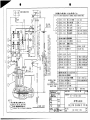
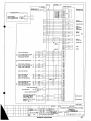
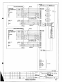
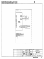
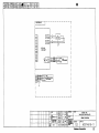
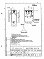
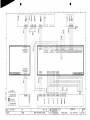
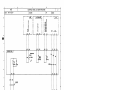
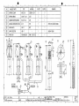
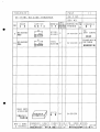
S K E L E T O N D I A G R A M OF P I P I N G
ff
j .M
IRULEMK
I
,_
B I
DAJE
.(IffilPfytt m g
n u n NO
|å f
R 4 - 2 0 0 - 1 52
I REV.
I R1
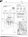
aMâ<Ôî«I(*A:^7^+*J: 1 ; 2. 5m) CgfltfBult.
3. « 7 7 ^ («Ah, *?!•• rt?*vft) BâaWtOÎT.
nifE >0>»J>l«'> I
I • I V I I
I
ORDER NO. M
IHinifB
»'«'jjSSBr^'Tr
e
^
IOWHEB « M
]
«
M
RULE« _
XL
H
I
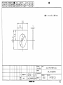
, m w KT-157B3
ï""
"
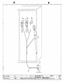
PIPING ARRANGEMENT
'^^PK^-ls'r 0 A
KAWASAKI HEAVY INDUSTRIES. LTD.
ri
KOBE JAPAN
(i
CM
_
^____^
MACHINERY DIVISION I
I
NARINE MACHINERY DECT . . . . . . .
« 8 ejtfttV*-
*
8
B
ffl
TYPES*
t«»»8i*at»)
W E
1/10
UT
O O D
-jAADo
«gi
-g-"af-
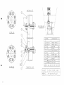
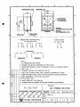
KT-32B ~ 300B3
TJD
|f
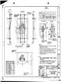
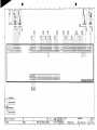
WEIGHT : a b . 80ka (DRY)
ORDER NO. * #
i R U L E l « TfifZ '
M * H I
T» "
I OWNER 3 X Î
DRAWN
8QL I^^^IÆB
5 I
^
80L LITER GRAVITY TANK ASSEMBLY
ft
«i^^few'"''^
*
*
R4-300-322
KAWASAKI HEAVY INDUSTRIES. LTD.
p^B8
KOBE JAPAN
(A39)
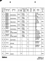
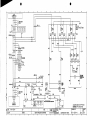
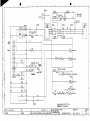
REVISION
|«i:THE RELIEF PRESSURE IS MODIFlED l t . l l . i l
M. 1SIIIIAIA.M.YAMANE
c « »«
PIPING
ITEM
MfB«B
DETAIL OF
FLANGE
*
«
STANDARD
(25A)
AI. A2
it*
JIS
(25A)
R
IP
B2291 J I S
.160
(50A)
3
i i un.iw
'M1 j
B2291 J I S
na
mu ut
nn
VI
B222O
293
ON
DPP
ON
OFF
pitua. » c
0.1IPI
FOR
ALARM
uiin.imh
9 • 9
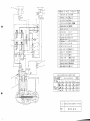
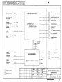
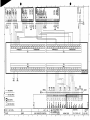
CONNECTION DIAGRAM
nu
mu. in.
DPP
mu. ne.
DP,
S
PRESS.
1. Hf |
ON
ON
DR^INTERLOCK
OIL HYD. CIRCUIT
SWITCH
SETTING
0-1
DIAGRAM
i»« tug)
ELECTRIC MOTOR
19
17
: 260ks
TO1A1_IT-E«CLO«!O tut
COOLES FLAME U P t
SP0-I8
AIR VENT PLUG
fn9*
CHECK VALVE
Tl»»»
CHECK VALVE
18
êiffi
6. BKÏ-2P
11383)
CXOA-XCN-GBP/S
CXHA-XDN
MANIFOLD
NBC5I00-5
PRESSURE SWITCH
GAUGE COUPLING
nnwi
100-62. 000
RI/4
MBVEOOO-2201
'01/4
fLUC FOR TEiT'01/4
TEST VALVE
COMMON BED
400-42. 000
G1/4
EM
SïSO-113-IONPl
G1/4
PRESSURE GAUGE
tiif
PRESSURE SWITCH
MBC6100-3
»It
TMA-M24X2-B
THERMO METER
19JH9
SUCTION FILTER
VLF-I2-100-12F
GAUGE CONNECTOR
1JL3
»II» miMTO» I HL«
CARTRIDGE(IOGIC)
ïifl*
DE6P-20-208
-WD24AL
* H » »
(JJ7)*
CMTHIItE(IELIEF) »AUE
RVEA-LDN
0M#
COUPLING
*
»
10TEIll/SI-ItA
JÜH1
DEX
25-8N8D993
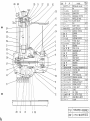
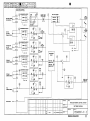
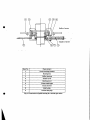
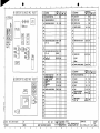
HYDRAULIC PUMP
«
*
TEN I
NAME OF PART
HACIIHEIY BIV
DC24V
ser pnei«. <s. i NPI
miKTiet rn UL «IT in
US«:
i
«
REMARK9
O'IY
ORDER NO. H
IIIIDR
uiimuemoiDcri
IUT)
nun
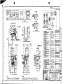
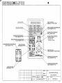
(2P3)KT-157B1/H3. KT-1B7B1/B3
it
*—}' *?• Çyf't^BDIH 46259. Pe 1 3. 5Tt
JIS F8S0I 15a. 15b. 16c. 20a, 20bcJ)*bT^J:t
eaan
* i
REMARK
CABLE GLAND SIZE FOR THE PRESSURE SWITCH 13 DIN 46259. Pa 13. 5.
THE EQUIVALENT GLAND SIZE O F JIS F8D01il S«. IS». 15c, 20i and 20 b
S,«!}!
SIDE
THRUSTER
H Y D R A U L I C PUMP U N I T
»Ol.O». 17 O»O. HO.
•»
R4-602-012
UMSAHI »CA»Ï imilllTIKa. LTD.
ï H0
RI
(A2I)
1
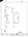
k6
(mm)
^
i
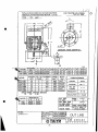
MODEL
F I
NO
G E
D
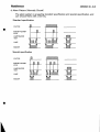
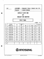
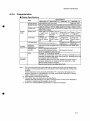
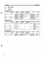
L1ALBLCLELGLLQLRLWSTUWZKHKL
*%V-132S ~FF265
2^52226523Ö3ÖÖ~4""^Ö442~80~8Ö"~0"38~8~5'IÖl5'36Ö244
|TIV-132M| FF265 l274i&4ol26S|23o|30o| 4 | 2O|46o| 8o| 8o| 0 1381 8[ 5 | i o | 1513601244|
J*w I MOnFT
^
™
I OUTPUT I NO. OF I CURRENT I SPEED I MASS I I
(kW)
POLES
(A)
(min-')
(kg)
^HV-132S
TIV-132S
TIV-132S
TTV-132M
TIV-132S
5.5
7.5
5.5
7.5
3.7
[TIV-132M 1
5.5
2
2
4
4
6
1
9.5
12.5
9.8
13.0
7.7
6
|
3440
3460
1745
1740
1150
11.0
Ca 67
Ca 71.5
Ca 64.5
Ca 78.5
Ca 67
[ 1150 | Ca 83.s]
VOLTAGE
NO. OF
PHASES
440 V
INSULATION
.
3
60
*
Hz
1000.-1.21
TRACK
M.AZAM1
^STAIVTI
* *
ELECTHJC C O . L T P .
15
B CLASS
I »A1N CABLE
ITPYCY - 4.0x 1 I A
SH CABLE
DPYC - X HAIN CABLE CLAND
25t> X i
SH CABLE CLAMP
-X STARTING METHOD
DIRECT, -Y-T!rr-eCttg=
150 5! AT DIRECT ST
I STARTING TORQUE | — » - AT Y STARr 1
l 3 H P A N C U i | U N 1 T | CHUSF k. T N O M A T J I
I>HOJ);CTION| mm CHECK T-SHlMOYAMt
SCÄÜCI /
DESIGN M.A2AM1
I
CONT.
I
s
^ h l MODEL I BEARING N O ~ ]
L S
>^i
- °- S " 132S
6308ZZ
6306ZZ
I 1 3 2 M I 6308ZZ | 6306ZZ |
BATB
RATING
FREQUENCY
SPACE HEATER (WINDING HEATING)
10
15V
2.6A
£MWGL
; 3,I9DO.4.2I.M.A
mMMnNUFMiW
COMMON REMARK
O U T I IMF
WU
I
t-IINC
OUAW. NO
GM 4 0 6 4 2 3
I^ I I I I I I I I 1 I I
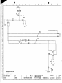
REVISION
a
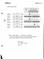
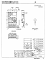
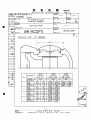
INSTALLATION
A T T E N T I ON
E TAPER PINS S H O U L D B E F I T T E D
BY T H E S H I P Y A R D A F T E R
I N S T A L L A T I O N O F T H E MOTOR
fi/<8
"
ALIGNMENT
B
*
a
LIMITS
PARALLEL
ECCENTRICITY
DECLINAT ION
GAP
Y
TO BE COMF11KB COUFLIHG COVEI
DDK'I TOUCH BUDE ANCLE I M S K I I I F I
AW PIPINGS
I M Y=6 4IRECQHENE0 VALUE)
HflitSfl X-YSO
ALLOWANCE
t<!È6tt
PSO 28mm
ALLOWANCE
Y«ax5l2 7RIH
Vnnil.Sia
. iBr3F1>Vf<lv9<l>W)t)tii-ltliilitlttlZt
(KM fi9IOo)
REMARKS
I TO
BE INSTALLED WITHIN INSTALLATION ALIGNMENT LIMIT ACCORDING
TO A B O V E T A B L E
2 T O B E A S S E M B L E D IN A C C O R D A N C E W I T H I N S T A L L A T I O N M A N U A L
3 TO B E FILLED U P INSIDE COUPLING WITH GREASE
4 TO B E ASSEMBLED COVER WITH MATCH MARK U P A N D TIGHTEN TOROUE
7 3 N m (750k 8 f c m )
TO M A K E A T A P E R E D
REMAER HOLE
BY T H E S H I P Y A R D
A
FIT'
SCIEI END IAPER FIN
412 * V f t < K
SPRING
WASHER
410
« I 6 X 2 2H 2 1 7 LOCKING WIRE
J i s B 1180 156
MIZX25
COUPLING
131 3F COUP
51
Bitumai
TYPE.mono
MM
I1LE Ultllll
»tut
45
3
33
0 95 0 95
32
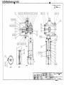
INPUT
14
SHAFT
09 0 9
S45C
IIHI7II0
155165
7Cr»IWIII
PARTS NO
NAHE OF PARTS
a
*
23 2
EST PICCI
HATERtAt
OR O N E ( }
HOTE
H «
-mnr
GEAR
ORDER NO
»fflOIEO
* I
CASE
C. L
£>)
C L
[RÏÏTËÏÏ
UI:
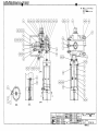
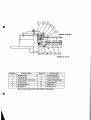
KT-I57B1/B3
IIIHMIII
FROM PROP. SHAFT
Mff
CHE« ED
*
fee
JCALE
R «
1/5
I
INPUI SHAFT-SF COUPLING ASS'Y
DRAWN
ft E
!*.'! H I 2 , 1 2
• • - " i n Dit «o
an - j j Q - n 11
Y
G4-200-T396
«AWASA<I HEAVY INDUSTRIES. LTD.
(A2II
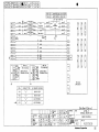
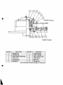
(jLfct PARALLEL
•^M
ECCENTRICITY
' gflfl
I
DECLINATION
1
•*I»8«:p*O. 28mm
ALLOWANCE
,
— I — | -x
,
RUNG SPACER
ic
o
,
NYLON NUT
Mavtil
HEX. SOCK. BOLT
oojnn
SS400
U A
SoCn M
4 3^5;
A
4
4A
e
R
GASKET
mum
FIBER
2_ J2Ï2Ï
FLEX
r-
SF SEAL RING
b
SF->-*u>?
.
T-GRIDMEMBER
I__L2i2lÜÖ
,
T-COVER
3
T/\-7Jl/\U B
2 j ^
1 j ; "
«
q •
Î
,TEH
U B
s,
PRIME MOVER DIV N I
I
I 1 I I I S
APPROVED
"Ttfffflf
N*X.
1
». p.
LJ
*
,
0
l
,
ALLOY
STEEL
,
^
S4 5C
S45C
1
1
JLL1
ZZI
MATERIAL " . " , ' [ ' ^ T ' " H T " » L r " T ' P I E "
a
a
I OWNER ZXÎ
8
TYPEga
F0R 0 N E (
'
"A 33
s B e
NOTES E »
i»<f - i > * - * «
ORDER NO. H *
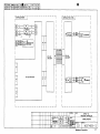
KT-157B3
IRULE««
I
I~»
6QHZ (11 3 Q T 1 0 )
c
3RD ANGLE
TIM
^ ^ * * RTE
1 / 5
* ^
-gfifâ-
s F ^'y^uv^fflaa
n^r
ft
T
~g—r
•«
SCALE , /
»""
*
l
i 9x v7 70 nL i
MM
12
DECKED
feg
a «
NEOPRENE
%t1vj
~. u
NAME OF PARTS
«a
\
„
rit/L
SCM435
_2
i
""
III
NEOPRENE
HEX. 30CK- PLUG
fl
8
PARTS NO.
! * * * = Y Ï Ï ? Ï * 1 i ' 6må
' AU OWANCE
tmHH
9Q
Y
' m = Y=6. «(STANDARD VALUE)
[ M « « : X-Y*O. 30B«
' ALLOWANCE
n
' I B t ä GAP
I
SF COUPLING ASSEMBLY
aI
^ ^ - I P j f i i W. HO.
^ _ _ t sg
DWG N O .
Hg
4
KAWASAKI HEAVY INDUSTRIES. LTD.
T"Ë^"
| |
KOBE JAPAN
(A3S)
8
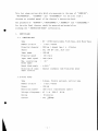
KAWASAKI
HYUNDAI HEAVY INDUSTRIES CO..LTD.
S.NO.H1630
SIDE THRUSTER
KT-157B3TYPE
TECHNICAL DATA
DELIVERY
YARD
5
KPMEI&
KPMEX» 1
1
ISSUE
KAW 'Ai aAKI
HEAVY IN DU51' R I E S , LTD.
MACHI NERYDIVISION
MARINE MACI4INERY DEPARTMENT
[ ORDEF* N 0 . 3 1KB068J
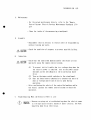
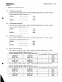
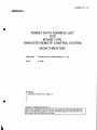
This list shows various data which are necessary in the case of
" MAINTENANCE " , " ASSEMBLY " and
" RUNNING " ,
" DISASSEMBLY " for the side ( bow )
thruster as attached manual of the thruster's instruction book.
The procedure of
" RUNNING " , " MAINTENANCE " , " ASSEMBLY " and
" DISASSEMBLY "
for the side (bow) thruster should be operated and worked after
studying the
I.
" INSTRUCTION BOOK " sufficiently.
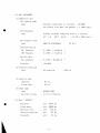
PARTICULARS
I .1
THRUSTER UNIT
Type
Number of units
KT - 157B3 Controllable Pitch Type, with Motor Base
1 unit/vessel
Propeller diameter
2200 mm ( skewed type ) x
Thrust
abt. 196 kN { abt. 20.0 ton }
Input power
1335 kW
Propeller speed
Input shaft speed
4 blades
315 r/min
1160 r/min
Max. controlling
blade angle
50 °
Rated blade angle
±18.8 °
Direction of input
shaft rotation
Counter clockwise view from prime mover
I .2 Prime mover
Type
Number of units
3 phase, Totally enclosed, vertical type
1 unit/vessel
Output
1335 kW
Revolution number
1200 r/min ( Synchronous speed )
Voltage x Frequency
AC
Rating
Current
3 0
3300 V
30 minutes
abt.
- 1 -
60 Hz
I . 3 AUX. MACHINERY
(1) Hydraulic unit
Oil service pump
Vertical screw type x 1 set/unit
Type
30 lit/min x 4.5 MPa { 46 kgf/cm
25-6N8D
} x 3440 r/min
Driving motor
Totally enclosed induction motor x 1 set/unit
Type
AC
3 d>
440 V
60 Hz
5.5 kW x 3600 r/min
DC solenoid valve
Type
DC 24 V
DE6P-20-208-WD24AL
Pressure switch
Pressure
0.4 MPa
{ 4 kgf/cm
}
OFF Pressure
0.3 MPa
{ 3 kgf/cm
}
5.5 MPa { 56 kgf/cm
}
ON
Relief valve
Set pressure
Strainer
150 Mesh
(2) Flexible coupling
Type
SF coupling
(3) Gravity tank
Capacity
Alarm level
80 1it •
30 1it •
(4) Hand pump
Type
ROTARY PUMP
Delivery volume
0.2 1it ./rotation
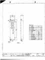
I .4 Mass ( WEIGHT )
Thruster
abt.
8600 kg
Prime mover
abt.
5800 kg
Hydraulic unit
abt.
260 kg
Flexible coupling
abt.
qi kg
Accesarry
abt.
50 kg
- 2 -
1130T-10
II .
OPERATION
II . 1
Interlock for prime mover
(1) Gravity tank oil level
Normal (checking by float switch)
(2) Control oil pressure
Normal (checking by press, switch)
(3) Blade angle
Neutral ( AB = 0 " )
±
Allowable range
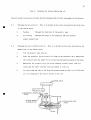
II .2
3 degree
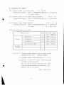
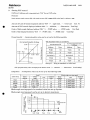
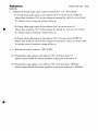
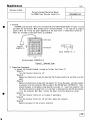
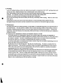
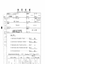
Rated draft
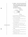
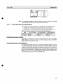
The draft should be kept shown in "fig.- 1 " at running.
Fore draft
:
df â
5.7 M
ftS (d r a f t )
fig.- l
II . 3
Oil temperature of the thruster
The kinematic coefficient of viscosity for thruster should
be kept the range of 40 ~
500 mm
/s { cSt } at running.
The corresponding temperature to the forementioned viscosity
is at about 10 ~
60 °C for the gear oil ISO VG 100
- 3 -
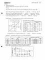
H . MAINTENANCE AND OVERHAUL
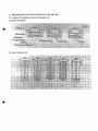
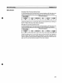
M . 1 Allowable range of starting torque
Measuring procedure :
:
11 ~
1Q N'iu
Refer to INSTRUCTION BOOK Part 4. (Inspection)
4.1 fig-2, fig-3.
IH.2 Allowable range of input shaft axis displacement
Measuring procedure :
: ^
0.3
mm
Refer to INSTRUCTION BOOK Part 4. (Inspection)
4.1 fig-4.
II.3 Allowable range of gear backlash
Measuring procedure :
:
0.30 ~
1.18
mm
Refer to INSTRUCTION BOOK Part 4. (Inspection)
4.1 fig-4.
R =
100.0
mm
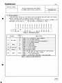
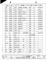
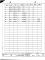
HI.4 Fastening torque of main parts
i
r
f-
1
1
T
Thruster
I
hI
hI
f--
-~i
T
| Item
Name of parts
Blade bolt
Fixing bolt
1
1
3
+
+
I
Nut for bevel gear
+
31
N•m
{ kgf • m
1030
{ 105.0 }
1079
{ 110.0
}
2079
{ 212.0
}
2393
{ 244.0
}
|
•+
+
|
|
•+ •
|
|
-\
|
H
I
Flexible
coupling
1
} i1
H
15
Fixing bolt
Fas tening torque
|
I
H
I
.j
Caution) (1) The parts number shown in list are found in the
INSTRUCTION BOOK FIG-1 " THRUSTER ASSEMBLY " .
(2) Allowable range of fastening torque
:
-5~0 %
(3) The part of thread and seatface should be coated
with MoS2 at fastening work.
But, the case of flexible coupling's bolt, MoS2
should be coated the part of thread only, the
seatface must be not coated.
( MoS2 : Molly coat )
- 4 -
5 Remachining of liner for shaft sealing device
In the case of that the oil leakage is happened from shaft sealing
device by unusual wearing out of liner, remachining of the liner
should be done for that repair.
Remachining allowable to be refered to " Table -1 " .
Then, supply interference to the sealing inside with spring force.
Table -1
unit
i
I
I
I
1
Type
1
1
: mm
1
1
| Outside dia. | Remachining
| Inside dia.
| Interference I
| of liner
| allowance
I of seal ring
| of seal ring |
|
| max. (per. dia. ) | (incl. spring) |
|
h
+
I KT - 157B3
|
I
I
+
260.0
|
+
1.5
i
|
+
256.0
I
M Caution of liner remachining
(1)
Roundness and cylindricity
: 5/100 mm
(2)
Roughness of liner surface
: 1.5 s ~ 3.0 s
- 5 -
|
i
H
4.0
|
i
Instruction book
KAWASAKI KT-B
SIDE THRUSTER
KAWASAKI
HEAVY INDUSTRIES, LTD.
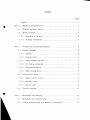
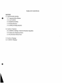
Contents
Page
General
"Part—1.—_ Operation and manipulation
1
3
1. 1
Thruster operation limits
3
1. 2
Operation manual
3
1. 2. 1
Operation of thruster
4
1. 2. 2
Stopping of thruster
5
Part 2.
2. 1
Construction and working mechanism
6
Thruster assembly
6
2. 1. 1
General
6
2. 1. 2
Propeller part
6
2. 1. 3
Power transmission gear
7
2.1.4
Oil feeding mechanism
8
2. 1. 5
Feed back mechanism
8
2. 1. 6
Shaft sealing device
9
2. 2
Pitch control device
9
2. 2. 1
Remote control system
9
2. 2. 2
Hydraulic unit
9
2. 2. 3
Gravity tank
2. 3
11
Flexible coupling
12
Maintenance and checking
13
3. 1
Maintenance and checking items
14
3. 2
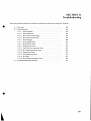
Trouble shooting guide (for thruster in operation)
17
Part 3.
11
Page
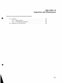
Part 4.
Inspection
21
4. 1
Docking inspection (Pre-disassembly inspection)
22
4. 2
Inspection of parts upon disassembly
24
4. 2. 1
Thruster proper
24
4. 2. 2
Flexible coupling
25
4. 3
Inspection after reassemble and restoration
26
4.4
Notification of inspection items to us
28
Disassembly and reassemble procedure
29
Disassembly of thruster proper
29
Part 5.
5. 1
5. 1. 1
Preparation for disassembly
5. 1. 2
Disassembly procedure
30
Reassemble of thruster proper
33
5. 2
29
5. 2. 1
Preparation for reassemble
33
5. 2. 2
Cautions and hints on reassembly work
33
5. 2. 3
Measurement items to be taken during reassembly
34
5. 3
Self-locking procedure
36
5. 3. 1
Propeller part
36
5. 3. 2
Propeller shaft part
37
5. 3. 3
Input shaft part
38
5. 3. 4
Flexible coupling
38
Ill
-Page
Part 6.
Charging- the system lubricating oil
39
6. 1
Charging the entire unit with oil
39
6. 2
Charging the servo cylinder with oil
39
6. 3
Recommended brands of lubricating oil
40
6. 4
Criterion of oil exchange
41
Part 7.
Initial starting after installation
42
Part 8.
Spare parts
44
Annexed drawings 1. THRUSTER ASSEMBLY
2. SKELETON DIAGRAM OF PIPING
3. SHAFT SEALING DEVICE
4. HYDRAULIC UNIT ASSEMBLY
5. DISK COUPLING
6. SF COUPLING
Remarks
This manual deals with general description on the thruster system. The contents are subject to
change due to specification of job.
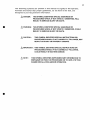
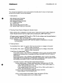
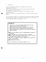
(1)
PREFACE
Read The Operation's and Foreman's Manual
This instruction manual provides important information concerning
proper equipment operating, assembling and disassembling. The safety of
yourself and others depends upon your care and judgment in
the process of the working and properly performing required
attention. Therefore, please take time to read this
manual thoroughly, and keep it with the machine permanently.
Accuracy and Completeness
Although every effort has been made to ensure the accuracy and
Completeness of this manual, Kawasaki cannot anticipate every
possible circumstance, use or misuse of the equipment which
might involve a potential hazard. Therefore, the warning and
information presented in this manual may not be all inclusive.
In addition to closely following Kawasaki's recommendations,
your are encouraged to familiarize yourself with applicable industry
safety guidelines, and exercise due care for the safety of yourself
and others in using this equipment, including the wearing of
appropriate protective apparel. Additionally, due to Kawasaki's
continuing efforts to improve and refine its products, the
specifications herein are subject to change.
Foreman Training
If after reading the installation manual you have additional questions
about the use of this equipment, or if you need operator, foreman and worker
training, please contact with KHI's branch or representative in the world.
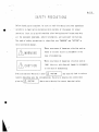
C2)
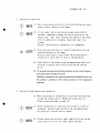
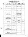
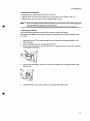
The following symbols are present in this manual to signify to the operator,
foreman and worker that proper guidelines, as set forth in the text, are
designed to provide pertinent information.
^
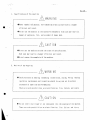
DANGER :
THIS SYMBOL IDENTIFIES SPECIAL WARNINGS OR
PROCEDURES WHICH, IF NOT STRICTLY OBSERVED, WILL
RESULT IN SERIOUS INJURY OR DEATH.
/^WARNING : THIS SYMBOL IDENTIFIES SPECIAL WARNINGS OR
PROCEDURES WHICH, IF NOT STRICTLY OBSERVED, COULD
RESULT IN SERIOUS INJURY OR DEATH.
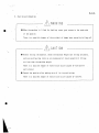
CAUTION :
THIS SYMBOL IDENTIFIES SPECIAL INSTRUCTIONS OR
PROCEDURES WHICH, IF NOT CORRECTLY FOLLOWED, MAY
RESULT IN INJURY OR PROPERTY DAMAGE.
IMPORTANT : THIS SYMBOL IDENTIFIES SPECIAL INSTRUCTIONS OR
PROCEDURES WHICH, IF NOT CORRECTLY FOLLOWED,
COULD RESULT IN MACHINE DAMAGE.
NOTE :
THIS SYMBOL IDENTIFIES SUPPLEMENTARY INFORMATION TO
EMPHASIZE OR POINT OR PROCEDURE OR TO GIVE A TIP FOR
EASIER INSTALLATION AND/OR OPERATION.
General
The side thruster is a transverse propelling device with its propeller mounted in the lateral
through tunnel in the hull such that the water jet generated by this propeller gives a lateral
thrust to the hull. Thus facilitating the departure of the ship from and its coming alongside
the pier. Also helping improve the ship's maneuverability when it is running at a low speed or
in a narrow waterway.
Kawasaki's KT-B type side thruster is a controllable pitch thruster having incorporated in it
a propeller pitch controlling mechanism. So planned that the propeller pitch can be remotecontrolled from the control stand on the bridge.
This device is composed of the actuating section comprising a drive motor. Flexible coupling and
thruster proper and the propeller pitch control device. Its features being as follows.
(1)
Adoption of 4~bladed skewed controllable pitch propeller which is effective for reducing
vibration.
(2)
Highly rigid construction and compact design. Hence easy installation.
(3)
Propeller pitch is controllable. This allows the use of a constant speed motor with its
revolving direction fixed.
(4)
The possibility of controlling propeller pitch also enables continuous and quick change
of the thrust in either port or starboard direction.
(5)
Easy operation for all operation controls from that for starting the motor to that for
regulation of the propeller pitch are collectively arranged in the control stand on the
bridge.
(6)
The propeller blade are capable of dismantling in the thruster tunnel by means of removing
the blade bolts.
The thruster can have its performance retained over a long period, if simple preoperational
checking and the recommended routine maintenance and checking procedures are observed.
This manual is intended to give cautions and hints on the operation of the thruster to be observed
as well as the maintenance and inspection standards.
NOTE : THIS INSTRUCTION BOOK IS MENTIONED ABOUT STANDARD TYPE SIDE THRUSTER.
FOR THE PROPER ITEMS OF EACH JOB, THE SEPARATE PAPER "TECHNICAL DATA" IS TO
BE REFERRED.
Part 1. Operation and manipulation
1. 1
Thruster operation limits
(1) Be sure to observe the specified draft.
(For the specified draft refer to the separate "Technical data. ")
If the draft is insufficient, it is not only interferes with the thruster exhibiting
the specified performance but also causes cavitation or air drawing, and the resultant
vibration may possibly cause damage to the device.
(Air drawing can be detected as marked hunting of the drive motor ammeter. )
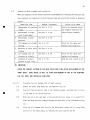
(2) A IMPORTANT:WHEN THE SHIP'S SPEED IS MORE THAN 5 KNOTS. THE VIBRATION OF THE
PROPELLER BY THE AIR DRAWING IS INCREASED. HENCE IT IS REQUIRED
FOR THE THRUSTER NOTTO BE OPERATED MORE THAN 5 KNOTS.
In some cases, it is also possible that air drawing is caused when the ship's speed
is below 5 knots. If it is the case, the propeller pitch is to be so controlled that
there is no risk of air drawing with the lower blade pitch zone.
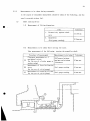
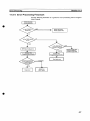
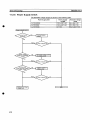
1.2
Operation manual
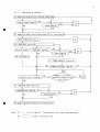
The thruster operation procedure is as illustrated in the flow chart on the next page.
Manipulation of the switches and thruster components is, as a rule, to be done from the
control stand on the bridge. Hence the change over switch on the motor control panel should
be set to "REMOTE".
The flow chart given is for the thruster of our standard type. Hence if the thruster
specifications are different in any respect from our standard, be sure to carefully study
them to find proper operation sequences for the remote control system and motor control
panel.
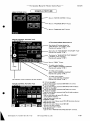
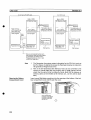
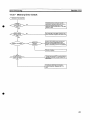
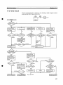
1. 2. 1
Operation of thruster
(1) Operation mode switch "Control power ON"
NO
Control power lamp ON
S\
YES
Alarm lamp ON
YES
TNO
(2) Operation mode switch "Main power ON" at local panel
( "MAIN SOURCE ON" lamp on }(3) "PUMP RUN" switch ON
I
NO
(Fan run signal )(j'PUMP RUN" lamp ON
YES
f
YES
Alarm lamp ON
J
NO
! Fan run lamp on Î
1(3') "POWER REQUEST" switch ON !
^_
----( "POWER AVAILABLE" lamp ON
->O<-
r
Ready to start lamp ON
)-N-°-
j
YES
(4) "THRUSTER RUN" switch ON
( "THRUSTER RUN" lamp ONJ-NO
YES
YES
I
(
Alarm lamp ON J
NO
(5) Start the pitch control by control dial
Note) (1)
(2)
*
;
is to be read as " Tracing cause and taking countermeasures "
! mark is optional item.
->
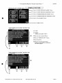
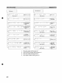
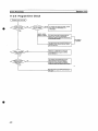
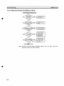
1.2.2
Stopping thruster
(1) Zero the blade angle by control dial.
"THRUSTER STOP" switch ON
( "THRUSTER RUN" lamp off
)
(3) "PUMP STOP" switch ON
( "PUMP RUN" lamp off
)
(4) "CONTROL POWER OFF" switch ON
( "CONTROL POWER ON" lamp off)
Part 2. Construction and working mechanism
2. 1
2. 1. 1
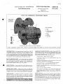
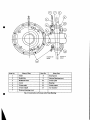
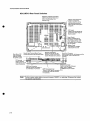
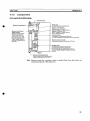
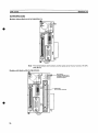
Thruster assembly (See annexed drawing Fig-1)
General
The thruster assembly is composed of a tube, propeller part, power transmission gear,
oil feeding mechanism and feed-back mechanism and the gear housing is fitted in the
tube by means of the bolts.
The propeller part, too, is located in the tube.
The power is transmitted from the motor through the input shaft (23), bevel gear (16)
and propeller shaft (32) to the propeller.
Propeller blade pitch is controlled by means of the hydraulic system. The propeller
part and gear case are filled with "gravity oil" at a pressure somewhat higher than
the draft of full load so as to ensure against ingress of sea water into the case
interior even in the event of seal failure.
2. 1.2
Propeller part
The propeller part is composed of propeller blades (1), propeller hub (6) and propeller
pitch controlling mechanism. This propeller part is connected by bolting to the end
face of the propeller shaft (32) such that the power is transmitted through a reamer
pin to the propeller part.
The flange is covered with a corrosion-proof shaft hood (9) with an "0" ring used
to seal against sea water.
In the propeller hub (6) the propeller blades moving mechanism is housed with the
crank disks (4).
The hydraulic reaction of the propeller blades (l) are held by the bearing portion
of hub while the centrifugal force is held by the thrust bearing of the hub and crank
disks (4).
The propeller pitch control mechanism is made up of a hydraulic servo motor composed
of cylinder portion of hub (6), crosshead piston (5), sliding blocks (7) -and crank
disks (4), and serves to convert the linear motion of the servo motor into a rotary
movement of the crank disk.
This rotary movement is transmitted to the propeller blades for control of the
propeller pitch by two pins.
"0" rings are used for sealing against sea water.
2. 1. 3
Power transmission gear
This is housed in the gear case and composed of an input shaft part, propeller shaft
part and bevel gear, and is to serve for transmitting the prime mover output to the
propeller.
The input shaft part has rationally arranged in it spherical roller bearings (21),
(24) and thrust bearing (25), while two sets of the spherical roller bearing (12),
(20) and thrust bearing (13), (17) are rationally arranged in the propeller shaft
part.
The bevel gear is a right angle reduction gear, composed of a pinion gear shaped on
one end of the input shaft (23) and a bevel gear (16) mounted on the propeller shaft.
This serving for transmission of power under simultaneous reduction of the motor speed
to the speed optimum for the propeller.
The bevel gear and individual bearings are to be lubricated by the gravity oil filling
the gear case. This charge of gravity oil is sealed securely by the two oil seals
of the input shaft part and the shaft sealing of the propeller shaft part.
8
2.1.4
Oil feeding mechanism
The oil feeding mechanism is made up of a oil tube (36), feed ring (18), oil entry
tube (37) and the bore through the propeller shaft (32), and serves to lead the
hydraulic oil from the hydraulic unit to the servo motor of the propeller section.
The oil feed mechanism has a pair of bores for hydraulic oil so that when the hydraulic
oil is supplied by either bore. The other one is used for discharging it.
The feed ring (18) houses the seal ring for preventing outflow of the hydraulic oil
into the gear case. When the command to feed oil is given by the control dial on the
bridge, the solenoid valve of the hydraulic unit is actuated and the hydraulic oil
is supplied through the oil tube, feed ring and oil entry tube (bore through propeller
shaft) to be supplied to the servo motor and the crosshead piston is displaced to
the predetermined position.
2.1.5
Feed back mechanism
This is a mechanism for transmitting the blade angle signal to the blade angle
transmitter (26) and remote control system, designed to detect the blade angle by
the stroke of the oil entry tube (37) and inputting it as a stroke signal to the blade
angle transmitter over the feed back lever (38) and chain (39).
This blade angle transmitter has a function of feeding back the blade angle to the
remote control system. And detecting the blade angle as it is indicated on the blade
angle indicator on the bridge and local indicator.
9
2.1.6
Shaft sealing device (See annexed drawing Fig-3. )
This is for sealing the gravity oil in the gear case against sea water, and is made
up of three seal rings (6), intermediate rings (3) (4), flanged ring (2), and cover
ring (5), and liner (1) that turns with the propeller shaft.
The clamp for each seal ring is fastened -to fit tight on the inner periphery of the
housing. Hence the clamp part is sufficiently sealed against oil as well as water.
The liner is made of a material highly resistant to corrosion and wear, and is fixed
to the shaft hood. The clearance between liner and shaft is made to lead gravity oil
to the propeller.
2. 2
Pitch control device
The device is composed of a remote control system for controlling the propeller pitch
and a hydraulic unit for regulating the blade angle.
2.2.1
Remote control system
The remote control system is of the electric control type, and serves to transmit
the command to change propeller pitch given through the control dial on the bridge
to the solenoid valve for the propeller blade angle to be adjusted accordingly. And
also hold the propeller pitch. It also serves to indicate the actual blade angle on
the blade angle indicator on the bridge. For further details of the remote control
device refer to the separate drawing "Remote Control System".
2.2.2
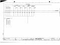
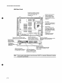
Hydraulic unit (See annexed drawings Fig-2 and Fig-4. )
The hydraulic unit consists of a hydraulic pump, solenoid valve, valve manifold to
which the cartridge valves are mounted having the following functions,
- Excess pressure relief, loading and unloading with the relief valve (2-7)
- Pilot pressure changing over for pitch control with the solenoid valves (2-3)
- Pressurized oil changing over to servo cylinder with logical cartridge valves(2-4)
- Checking of oil ways with check valve (2-18)
10
The oil of the gravity tank (4) is sucked by the hydraulic pump (2-1) through the
strainer (2-6), and is pressurized, is delivered through the logic valves (2-4)
which are controlled with the pressurized pilot oil by the solenoid operated valve.
When the command to change the propeller pitch is given, the port of the solenoid
valve is opened, the pressurized pilot oil from the vent port of relief valve operates
the logic valves to make oil circuits for moving the propeller pitch supplying the
hydraulic oil to the servo cylinder. On reaching the propeller pitch to the set
position the solenoid operated valve is returned to the neutral position to release
the pressurized pilot oil to the pump suction lines to close all logical valves.
Accordingly the oil from the pump is unloaded through the relief valve to the
gear case.
The oil supplied to the thruster during holding of the propeller pitch or during pitch
changing is filled with the gear case, and lubricates the bearings, gears etc. (Oil
bath lubrication applied). After that it circulates back to the gravity tank. For
protection of hydraulic unit a relief(2-7) is provided onto the manifold.
2.2.2-(l) Solenoid hydraulic operated valve (2-3)
This is a changeover valve for the pressurized pilot oil to the cartridge
valves(2-4) which change over the hydraulic oil to the respective servo cylinders
according to the command given by the remote control system.
(The solenoid hydraulic operated valves are hereinafter referred to generally as
"solenoid valve".)
11
2. 2.2-(2)
Cartridge valve (2-4)
The cartridge valves serve to feed the hydraulic oil to the respective servo
cylinders according to the pressurized pilot oil from solenoid valve (2-3).
2. 2. 2-(3)
Pressure switch (2-8)
In order to operate the logical valves, a certain minimum of pilot pressure is
required.
This pressure switch is for confirming the line pressure. If the line pressure
is fallen below the required minimum, this pressure switch is actuated, and the
alarm lamp on the bridge is lit. And also this switch is composed the start interlock
of the drive motor. As an optional item the pressure switch is
separately provided for interlocking circuit.
2. 2.2-(4)
Check valve (2-17, 2-18)
The check valves are fitted for the appropriate operation of the cartridge valves
(2-4).
2.2.3
Gravity tank (See annexed drawing Fig-2)
The gravity tank (4) serves to apply the gravity oil pressure to the thruster proper
so that the lubricating oil pressure in the gear case is kept higher than the pressure
of the ambient sea water, and also is used as oil tank for the hydraulic unit.
The float switch (5) with two contacts constantly monitors the system oil level and
lights up the alarm lamp on the bridge when it has fallen below the specified level
and also is composed the start interlock of the drive motor.
12
2.3
Flexible coupling (See annexed drawing Fig-5, Fig-6.)
The flexible coupling is for transmitting the drive motor's output to the thruster and
also serves to absorb the deviation between the motor axis and the input shaft axis of
the thruster at the time of installation. The installation error of the flange distance.
Motor - thruster alignment error due to deformation of the hull etc.
The type of the flexible coupling.
Disk coupling (Fig-5) : Flexibility by disk element
i
SF coupling (Fig-6)
: Flexibility by grid member
13
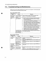
Part 3. Maintenance and Checking
In the event of trouble or failure, take countermeasures without delay according to this manual,
but KHI cannot anticipate every circumstances which might involve hazard.
So, to be described below are the recommended practice of "Routine maintenance and checking" and
"Trouble shooting guide (for thruster in operation)".
Checking of the individual sections and parts is to be carried out periodically about the items
enumerated in the table below under the head "checking items".
The inspection intervals are given as rough guide or hint, hence the proper interval is to be
determined with the frequency of thruster operation taken into due consideration.
Fouling of the propeller blades or of the "water path" in the tube are bound to cause an undue
drop in thruster performance, hence it is advisable to take every opportunity to clean them. For
the items of docking maintenance and checking such as cleaning of water paths refer to "Part 4-4. 1
Docking inspection".
Itemized records shall be kept of every maintenance checking, and such records with the
checking interval be reported to us together with the inspection findings on the items
enumerated in Part 4 "Inspection".
14
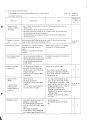
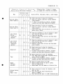
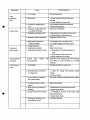
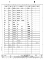
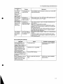
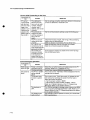
3. 1
1.
Maintenance / checking items
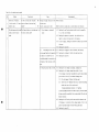
Checking item
Interval
Abnormal noise, abnormal
Routine checking
vibration.
Description
Checking of drive motor, flexible
coupling, thruster proper, hydraulic
( pitch control oil) pump.
2.
Checking of gravity tank oil
Monthly
level.
Checking by the oil level gauge of the
gravity tank.
For routine level checking there is an "alarm lamp" provided on the bridge.""
Periodical checking by the said level gauge is, however, recommended.
Checking by the "alarm lamp" on the bridge is to be done with the thruster
operation mode switch set to "Control power ON". Checking over, the same switch
^ set to "Control power off".
_,
3.
Cleaning of hydraulic unit
The strainer is provided with a color
strainer.
indicator (black—normal, redclogged).
Monthly
4.
Ingress of sea water into the
Take a sample from the oil sump in the
gear case interior.
bottom of the gear case using a hand
pump, and check it.
5.
1. Flexible coupling (SF coupling)
Feeding grease.
(l) Grid element.
2.
Plummer block.
Every 3
3. Coupling of hydraulic oil pump.
Months
4. Thruster proper : Input shaft's oil
seal.
5. Motor : The parts deemed necessary.
15
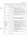
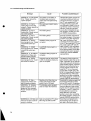
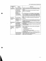
6.
Checking item
Interval
Hydraulic oil pressure
Every 3 months
Description
1. Measurement to be taken of the
measurement.
following by means of the hydraulic
unit's pressure gauge.
(With thruster in operation.)
(1) Blade angle : 0° , 10° , max.
(2) Turning direction : Right, left.
7.
Frequency of solenoid valve
Every 3 months
1. Blade angle : 0°
actuation and oil
measuring time : 3 min.
temperature.
Actuation frequency to be measured
(With thruster in operation. )
under this condition.
2.
Oil temperature to be measured with
the thermometer attached to the
hydraulic unit.
8.
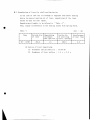
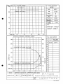
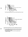
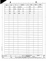
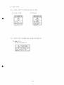
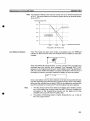
Propeller pitch and required
input power.
A NOTE:
Twice / year
Measure the working current of the
drive motor (rack scale reading)
under the same conditions as given in
AFTER LONG TERM LAY 1NG-UP MORE
item 6.
THAN TWO (2) MONTHS, INPUT
(A sample of measurement recording
POWER MIGHT BE INCREASED DUE
sheet is given in Fig.1.)
TO FOULING BY MARINE GROWTH ON
THE TUBE AND PROPELLER. IN
CASE OF THAT, TO AVOID SUCH
CASE OPERATE THE THRUSTER
PERIODICALLY DURING LAYING
-UP.
16
Interval
Checking item
9.
Description
Checking of remote control
1. Power source voltage.
system.
2. Checking for loosening on
terminals, relays and
Twice / year
potentiometers.
3. Function of pilot lamps and buzzers
by lamp / buzzer test switch.
10. Confirmation of blade anglle
Twice / year
1. Start the hydraulic (pitch control
oil) pump, and adjust the control
indicator.
dial to "0".
At the same time confirm that the
indicating needle of the blade angle
indicator and blade angle transmitter
are at point "0".
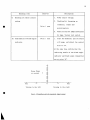
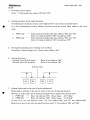
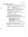
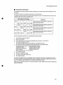
Horse Power
or current
max.
*—
Turning to the left
—
Î
O
—»
max.
Turning to the right
Fig.1 Propeller pitch required input power
17
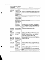
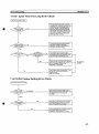
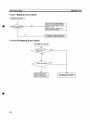
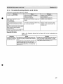
3. 2
Trouble shooting guide (for thruster in operation)
In the event of trouble or failure, take count ermeasures without delay according to this
manual, but KHI cannot anticipate every circumstances which might involve hazard.
If the cause is traced, eliminate it before resuming thruster operation.
If the cause of the trouble cannot be detected after careful checking following the
trouble-shooting guide below, please notify us without delay.
18
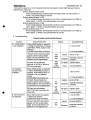
Check list of trouble-shooting guide
No.
Drive motor / hydraulic
1.
Check point
Trouble
Are the set values for the power • YES
( pitch control oil ) pump source voltage and staring timer '
wouldn't start.
normal?
;
Shortage of supply voltage or timer Check and repair.
setting error.
NO
Electric system out of order.
The alarm lamps on the bridge Which lamps light up on the bridge and / or (l) Over loading or tripping of
light up and the buzzer
Countermeasure
Cause
the local control panel?
Check the electric system such as control panel, motor interior.
1-1)
(e. g. rope), and cleaning.
motor.
sound.
Checking for sea floating objects sucked in by the propeller
1-2)
2.
Checking for deposits on propeller, tube inside wall etc.
(parts in contact with sea water), and cleaning.
1-3)
In case tripping, checking the condition of motor trip and trace
the cause.
1-4)
(2)
Overloading of motor for oil 2-1)
service pump. When the oil temperature 2-2)
has fallen to be below 0°C, the
2-3)
Checking for cause (5).
Checking for clogging of suction strainer, and cleaning.
Checking for sticking of relief valve and check valve.
Checking for cause (5).
overloading might be occurred due to
increasing of the resistance in the
pipe.
(3) Drop of gravity tank oil level. 3-1)
3-2)
Checking for oil leakage out pipings, couplings etc.
Checking for oil leakage through input shaft oil seal.
If oil leakage is detected, disassemble the seal by the procedure
given in Part 5. 5. 1.2-(5), and check following items.
(1)
Oil seal damaged - Replace the broken part.
(2)
Sleeve worn off - Remachine the sleeve, finish with buffing
without the trace of the cutting tool.
Maximum remachining tolerance : 0. 5 mm/diam.
In case disassembly work has to be done at the sea, the work should
be done as quickly as possible lest sea water should flow into the
thruster interior.
3-3)
Checking for oil floating on the sea around the thruster tube.
If floating oil is detected, feed a proper amount of oil to the
gravity tank and arrange for early docking and repair.
3-4)
Checking for cause (5).
19
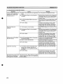
Na
Trouble
Check point
Countermeasure
Cause
(4) Drop of hydraulic oil pressure. 4-1)
Checking for air suction through suction piping and clogging of
strainer.
4-2)
Disassemble and check the valve and pressure switches in the
hydraulic unit.
(l)
Loosening of the relief valve
set pressure adjusting screw
and damage of its spring
(2)
Sticking of check valve and
damage of its spring
(3)
4-3)
Are the pressure switch setting and function proper?
Checking for cause (5).
(5) Trouble in electric system such Check for faults in the electric system such as loosening of terminal and
as malfunctioning of relay.
O
0.
Undue impact or vibration
1. Is the drive motor normal?
YES
Trouble on thruster side.
Check about 2.
NO
Internal trouble of motor.
Disassembly and checking.
felt.
2. Is the flexible coupling
YES
NO
normal?
3.
Measure the gear's backlash. In(For the measuring method
timer missetting.
Check about 3.
Broken of grid member (disk
Disassemble, check, then stop thruster operation. And replace the broken
coupling), element (SF coupling).
parts.
Wear of bearing in thruster.
If the measured value is in excess of the permissible limit, stop thruster
operation, And arrange for docking repair (replacement of the worn out
creased
bearing) as soon as possible.
refer to Part 4, Inspection
4.1-(9).
Not in- Damage to impeller due to hitting
creased
4.
Propeller pitch
un-controllable.
Arrange for dry dock checking.
against foreign object.
YES
Trouble in hydraulic system.
If the pump is normal, check about 2, and after.
control oil) pump running?
NO
Trouble in electric system.
Check electric system.
2. Is it possible to pitch control
YES
(1) Trouble in electric system of
l-l)
1. Is the hydraulic (pitch
with the solenoid valve spool
Check electric system.
remote control device.
(2) Damage to solenoid valve coil. 2-1)
changed over manually?
NO
Trouble in hydraulic system.
Disassemble and replace the bad component.
Check about 3.
20
No.
Check point
Trouble
3. Is the hydraulic oil pressure
Countermeasure
Cause
YES
normal?
(1) Sticking of cartridge valve
Disassemble and check.
(2) Loosening of relief valve
Readjustment of set pressure ( For the adjusting procedure refer to Part
adjusting screw
(3) Sticking of check valve
4.4. 1-(1O)).
Disassemble and check if the relief valve set pressure is reached or
exceeded.
(4) Trouble inside thruster
NO
Arrange for dry dock checking of feed-back and pitch-changing mechanisms.
(1) Air suction, clogging of filter 1-1)
and malfunction of valve
(2) Trouble inside thruster
Take the countermeasures proposed under No. 2-(4)(Drop of oil
press.) 4-1), 4-2).
Dry dock for checking oil supply mechanism and servo cylinder.
21
Part 4. Inspection
In order to maintain smooth thruster operation it is highly important to carefully check every
part of it at each docking and also keep running records of thruster operating conditions, to
say nothing of daily maintenance/ checking, (See Part 3.).
To be described and explained here are the procedure of inspecting the thruster as a whole
including the maintenance checking items requiring dry docking with the inspections involved
divided into the following three.
(1)
Dry dock inspection (pre-disassembly inspection)
(2)
Disassembly (overhaul) inspection of parts
(3)
Inspection after reassembly
Records should be kept of every inspection item involved.
Now described is the procedure of thruster overhaul.
IMPORTANT:OVERHAUL ACCORDING TO THE SCHEDULE GIVEN BELOW SHOULD BE DONE FOR CLOSE
INSPECTION OF ITS COMPONENTS EVEN IF NOTHING WRONG HAS BEEN FOUND IN THE
ROUTINE MAINTENANCE/CHECKING ETC.
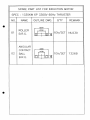
NAME OF MACHINE
STANDARD INTERVAL
DESCRIPTION
1. THRUSTER PROPER
DISASSEMBLY / CHECKING
2. FLEXIBLE COUPLING
5 YEARS
3. DRIVE MOTOR
MEASUREMENT OF
INSULATION RESISTANCE.
DISASSEMBLY / CHECKING
4. HYDRAULIC UNIT
DISASSEMBLY / CHECKING
22
4. 1
Dry dock inspection (pre-disassembly inspection)
Remark : ( A )
O
If nothing abnormal is found in the routine maintenance/checking (See Part 3.), follow the inspection
interval given in the table below.
Method/procedure
Inspection item
Remedy
: Recommendation
: Necessary work
Inspection interval
(year)
2—3
1.
Cleaning of water paths,
confirmation of locking and
repair painting.
1.
2.
3.
4.
Removal of deposits such as marine growth on the inside wall of tube, gear case and propeller surface , and
cleaning of the same.
Check locking of bolts in thruster, and repair if any of them is fallen off.
Repair painting of water-contact parts where paint coat is stripped or affected. (The water-contact parts are
anti-corrosion painted except those made of stainless steel).
The inside of the fairing cover, which comes into contact with the sea water should be cleaned and repairpainted with particular care.
2.
Replacement of anti-corrosive
anode.
The anti-corrosive anode should be renewed each time the ship is docked. (The life of the anti-corrosive anode
is taken to be about 2.5-years in case of the standard specification.)
3.
Check of system oil properties
Take a sample of the oil collecting on the bottom of
the gear case using a hand pump, and check its
properties.
(This analysis is to be arranged for by the shipyard
or the owner. )
Replace the charge of system oil, if it is contaminated
with sea water etc. or found badly deteriorated.
4.
Check of blade angle indication
at pitch transmitter
1.
2.
Start the oil service pump of the hydraulic unit.
Change the propeller pitch by means of the control
dial on the bridge and check to confirm matching of
the scale reading between the propeller hub and
the pitch transmitter.
Do matching of scale readings with that of propeller hub
as reference.
5.
Relief valve set pressure
confirmation test
1.
2.
Start the hydraulic pump of the hydraulic unit.
Move the spool of the solenoid valve by hand to
bring the servo piston to the end of the cylinder
watching the pressure gauge.
Confirm the relief valve set pressure by means of
the pressure gauge.
The relief valve set pressure is P=5.5MPa
Remove the fairing cover.
Clean the gear case and propeller.
Confirm that the oil level in the gravity tank is
as specified.
Leave it to stand for 1 day after confirmation of
the oil level to check for oil leakage.
1.
3.
6.
Leakage test of likely
components
-1
-2
-3
-4
Input shaft oil seal
Shaft sealing device
Propeller blade disc seal
Other seals
1.
2.
3.
4.
1.
2.
3.
Attach a lever to the coupling as same way for the
measurement of the starting torque.
Drive a wooden wedge between the propeller blade
and the tube in order to lock the propeller against
rotation.
(Remove the wedge after measurement. )
Set a dial gauge on the lever of the coupling and
move the coupling to measure the backlash. (See Fig.4.)
Each time the ship
is docked.
O
There is difference of more than 0.4MPa between the
pressure gauges on the pump discharge side and that on
the servo cylinder, hence be sure to do pressure setting
on the pump discharge side.
2.
3.
4.
7. Measurement of backlash
5
1.
2.
O
If oil leakage is detected, disassemble the parts
involved, and replace the seal packing, if necessary.
Oil leakage through the oil seal assembly ... Replace
Each time the ship
the part/s found bad or displace the lip contact part.
is docked.
Oil leakage through shaft water seal ... Replace the
part/s found bad or re-machine the liner.
(Exchange the oil of shaft sealing device.)
^Possible for KT-157B type and over to replace seal rings
by the way of bonding.
Feed grease to the input shaft oil seal, regardless
of oil leakage.
Record the measured values.
For the permissible limit refer to the "Technical
data".
O
o
23
Method/procedure
Inspection item
8.
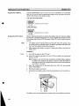
Measurement of starting torque
1.
2.
3.
9. Measurement of input shaft
displacement
1.
2.
10.
Checking of wear of gear tooth
face
1.
2.
11.
Measurement of oil feed
ring - seal ring clearance
1.
2.
3.
12.
Inspection interval
(year)
Remedy
Remove the flexible coupling.
Attach a lever to the coupling as shown in Fig. 2
and measure the starting torque.
The starting torque can be measured, if so desired,
with the flexible coupling connected as shown in
Fig. 3.
1.
2.
Remove the flexible coupling and attach an eye bolt
to the coupling. (Do this with the coupling
retaining plate fitted.)
Pull up the coupling and measure the displacement
with a dial gauge. (See Fig. 4. )
1.
2.
Let out the system oil in the thruster using a hand
pump or through the drain hole in the propeller
hub.
Open the checking cover and check meshing of the
gears inside.
Contact us if there is any abnormal indication such as
pitching or scouring.
Completely drain the system oil, and remove the
gear case cap.
Remove the return lever and oil tube and
disassemble the feed ring.
Measure the dimensions to be controlled. (See the
sketch on the right. )
3.
Record the measured values.
For the permissible limit for starting torque refer
.to "Technical data".
The values measured with the coupling connected
provide good references for later measurements
under the same condition. They are, however,
to be taken as mere guide for they include the
motor starting torque.
Record the measured values.
For the permissible limit refer to the "Technical
data"
J,
)
r^
2~3
5
(A)
O
(A)
O
(A)
o
Record the measured
values.
~1
o
tl Wi ft1 ^ f
CD
©
©
\
I 1
o
Complete overhaul
R
Measurement
procedure oi
backlash
F* • -Measure w,i th a
tensionmeter
Fig. 2 Procedure of measuring starting torque
Fig. 3 Procedure of measuring starting torque
Fig. 4 Procedure of measuring input shaft displacement
4.2
Inspection of parts upon disassembly
Do inspection of the following parts when the thruster proper and flexible coupling are disassembled.
If any of them is found damaged, please notify us without delay.
4.2. 1
Thruster proper
Inspection item
1. Measurement of
clearance
Inspection point
1. Feed ring - seal ring clearances
2.
Action to be taken
Record the measured values.
Clearance between crank disk and bearing of hub.
3. Clearance between slide block, crank disk pin and crosshead piston.
2.
Color checking
3. Wear of and damage to
1. Rounded root of propeller shaft flange and spline
If any, defect is discovered, please
2.
Input shaft keyway
notify us without delay and do
3.
Entire gear tooth face, and gear wheel spline
necessary preparation for replacement
4.
Journal of propeller blade
of the part/s involved.
1. Lip-contact part of the sleeve for input shaft oil seal
Remachine the liner.
2.
Lip-contact part of shaft sealing liner
Remachine the liner.
3.
Contact surfaces of inner, outer race and roller
Replace the parts affected.
rotary part
4.
Condition of gear tooth Tooth bearing and tooth face condition of pinion gear and bevel gear
Repair or replace.
face
tND
Inspection item
Inspection point
5. Damage to sliding part 1.
Inside of propeller hub.
2.
Sliding surface of crosshead piston
3.
Sliding surface of crank disk pin and slide block.
4.
Sliding surface of oil entry tube.
Action to be taken
Record or replace.
6. Packing for sealing and 1. The packing for sealing ("0" ring ) should be replaced each time the assembly is disassembled.
oil seal
2.
Oil seal : Check the lip etc. and replace the seal if anything wrong is detected.
The standard replacement interval for oil seal is 4 years.
4.2.2
Type
Flexible coupling
Inspection item
Action to be taken
Disk
1.
Checking of the crack and/or abnormal injuries on the disk element.
Replace the disk element.
SF
2.
Checking of the crack and/or abnormal injuries on the grid member.
Replace the disk grid member.
(S3
en
26
4. 3
Inspection after assembly and restoration
When any component of the thruster has been disassembled for checking and some part has
been replaced, do inspection on the following items and record the results or measured
values.
Inspection item
1.
Measurement of starting
Method / procedure
See Part 4. 4. 1-7.
Record the measured values
and compare them with the
torque
2.
Action to be taken
Measurement of input
See Part 4. 4. 1-8.
values before assembly.
shaft displacement
3.
Measurement of gear
See Part 4. 4. 1-9.
backlash
4.
5.
Oil leakage test of shaft See 4. 3.-( 1).
Trace for the cause and
sealing
replace seal rings etc.
Matching of pitch scale
See Part 4. 4. 1-3.
reading
6.
Oil leakage test of
See Part 4. 4. 1-4.
replace seal packing.
thruster as a whole
7.
Checking of contact
Trace for the cause and
See 4. 3.-(2).
Send the test record to us.
pattern of gear tooth
IMPORTANT :
CHECK THE CONTACT PATTERN OF THE GEAR TOOTH EACH TIME AFTER REPLACEMENT OF THE
INPUT SHAFT, BEVEL WHEEL AS WELL AS AFTER REPLACEMENT OF ANY OF THE BEARINGS
FOR THE INPUT AND PROPELLER SHAFTINGS.
4. 3-(1)
Procedure for oil leakage test of shaft sealing
(-1)
Remove the drain plug under the intermediate ring (3)
(-2)
Feed oil from the gravity tank to the thruster proper, and keep the oil level
in the tank at the specified Level.
(-3)
With the oil in the tank kept at the specified level, leave it to stand for 8
hours and then check for leakage through the drain hole in the intermediate ring
(3).
(-4)
After the oil leakage test screw in the drain plug, remove the oil inlet plug
and fill in the lubricating oil between the seal rings #2 and #3.
27
(-5)
Lock the oil inlet plug and drain plug. The oil leakage test is now over.
If the oil leakage out of the thruster (at various parts of it) in the step (-3) of this
test, the "oil leakage test of the thruster as a whole" can also be done simultaneously.
4. 3-(2)
Procedure of checking gear tooth hearing
This is to be done in the course of assembly.
This means that it is to be done with the input shafting fitted with the coupling
and coupling retaining plate, and with propeller shafting "ready for fitting"
with the feed oil ring assembly.
(-1)
Do tooth bearing adjustment for the input and propeller shaftings using the
provided shims.
The backlash adjustment can also be done simultaneously.
(This adjustment is to be done with the input shaft lifted. )
(-2)
Adjustment over, pull the input shafting out from the inboard side and coat the
pinion gear with red lead.
(-3)
Set the shafting in the thruster, turn it with the shaft lifted several turns
and then pull out the shafting.
(-4)
Take a print of the pinion gear tooth bearing using an adhesive tape or the like,
and add it to the test record.
(-5)
Then incorporate the shafting definitively, and checking of tooth bearing is now
over.
28
4. 4
Notification of inspection items to us
After completion of the inspections 4. 1, 4. 2 and 4. 3 mentioned above, notify us of the
respective inspection records.
-1)
Date"and place of inspection
-2)
Kinds of inspection .... Routine dry dock inspection (each time the ship is
docked), inspections after disassembly and reassembly.
-3)
Inspection items, actions taken and measure values These should be notified to
us without fail, the following in particular.
(1)
Measured value of starting torque
(2)
Measured value of backlash
(3)
Measured displacement of input shaft
(4)
Feed ring - seal ring clearance
(5)
Records of tooth bearing
-4)
Details of routine maintenance/checking and checking interval
-5)
Special data
(1)
Total running hours of the thruster
(2)
Troubles experienced, if any, with description of each case
(3)
Others
29
Part 5. Disassembly and reassembly procedure
5. 1
Disassembly of thruster proper
5.1.1
(-1)
Preparation for disassembly
Set a trolley
(The main components of the thruster are to be taken outboard in the way
illustrated in Fig. -7, hence a trolley or a proper substitute should be provided. )
(-2)
Have ready the required special disassembly tools and seal packings for the
individual joints.
• Special tools
See the annexed
"List of special tools"
• Seal packings
See the annexed
"List of spare parts"
(-3)
Provide an oil pan for receiving the oil collecting inside which will flow out
as the thruster is disassembled.
(-4)
Do pre-disassembly inspection (Part 4. 4. 1) and record the result itemize.
(-5)
Set the propeller blade as illustrated in Fig.-6, and let oil out using a hand
pump or through the drain hole in the propeller hub.
(-6)
Check the match-marks in the joints. (Match-marks are stamped at each joint before
shipment from the shop).
(-7)
Remove the gear case Cap.
5.1.2
5.1.2.-(l)
Disassembly procedure (Annexed drawings Fig-1 and Fig-3)
Dismantling the propeller shaft
5.1.2.-(2)
Remove the gear case cap (19)
Disassemble the feed ring
Dismantle the feed ring (18) with the sea-rings and outer ring
of the thrust bearing.
Dismantle the follower ring from the oil entry
tube (37).
Disassemble the feed ring (18) and take out the sealing rings from
the feed ring casing.
Disconnect the chain (39) from the return lever
(38) and sprocket.
Note:
Disconnect the oil tubes (38) from the feed ring
assembly (18) and draw out from the gear case
(22).
Measure clearance between sealing and seal shaft.
5. 1.2. -(3)' Disassembling the propeller hut (Ref. fig. 8)
Pull out the follower ring from the oil entry tube (37).
Dismantle and disassemble the feed ring.
Disassemble the feed ring part.
Remove the fairing cover (33).
Ref. fig. 7
Hang the propeller hub (6) with rope.
Hang the propeller hub (6) with rope.
Loosen the fixing bolts (34).
Fit the suspension tool onto the bearing housing
(11).
Draw out the propeller shaft (32), bearing
housing (11) and propeller part from the tunnel.
Disconnect the propeller hub part from the
shaft.
Draw out the propeller hub part from the tunnel.
Remove the oil entry tube (37) from the hub.
Full out the crosshead piston (5) form the hub.
Remove the sliding block (7) from the crank disk (4).
Dismantle the liner (Fig-3-(1)) of shaft
sealing (10) from the shaft hood (9) and fit the
mounting strap (Fig-3-(15)) on the shaft
sealing device.
Dismount the inner rase of the thrust bearing
(17) and radial bearing (20).
Dismantling the propeller blade (1).
Take out the crank disk (4) from the propeller hub (6).
Finished
Remove the nut for the bevel wheel.
Pull out the bevel wheel (16).
Dismount the thrust bearing (13).
5.1.2.-(4)
Loosen the bolts on the flange ring (Fig-3-(2))
of the shaft sealing (10).
Dismantling the propeller blade
Screw out the propeller blade bolt (3), and remove the
propeller blade (l).
Pins (2) will leave on the crank disk (4).
Drawn out the bearing housing (11) toward the
bevel wheel.
Dismount the radial bearing (12)
Pull out the shaft sealing (10) from the
propeller shaft (32).
Take off the shaft hood (9).
Finished
CO
o
5.1.2- (5)
Disassembly of input shaft part
5.1.2-(7) Disassembly of oil seal assembly only
Remove the flexible coupling (28) and drive motor or intermediate shaft.
Disconnect the connection piping of outward
Attach the eye bolt to the coupling (28), lift the input shaft
part as a whole, and haul it toward the inboard side.
Remove the pipe coupling-with-stuffing box (27).
Remove the coupling retaining plate.
(See Fig. 5)
Pull the coupling out of the shaft.
Remove the oil seal cover.
Pull out the sleeve for oil seal (29).
Remove the shaft key.
Pull out the spring housing above the thrust bearing.
:J\NOTE :BE CAREFUL NOT TO LOOSE THE
SPRING IN THE HOUSING.
Pull out the stuffing box (27).
(The oil seal (29) is housed in the stuffing box.)
Displace the bearing housing (30) toward the pinion side.
Take out the oil seal (29).
Remove the clamping nuts.
CANOTE : CHECK THE OIL SEAL AND SLEEVE.
Pull out the thrust bearing (25) and spherical roller bearing (24).
Pull the bearing housing (30) out of the shaft.
Remove the bearing stopper.
Pull out the spherical roller bearing (24),
Disassembly is now over.
5. 1. 2-(6)
fig-5
Disassembly of shaft sealing (Annexed drawing Fig~3)
Remove the mounting strap (15) and pull out the liner (1).
f
Take out the seal rings (6), while disassembling the cover
ring (5) and intermediate ring (3), (4).
Examine the liner (1) and seal rings (6) and then refit
them in place.
^IMPORTANT :
1) POSSIBLE FOR KT-157B TYPE AND OVER TO REPLACE
THE SEAL RINGS BY THE WAY OF BONDING>
2) IN REFITTING THEM, FILL GREASE BETWEEN THE SEAL
RINGS #1 AND #2.
3) DRAIN THE CONTAMINATED OIL FROM THE DRAIN PLUG
BETWEEN THE SEAL #2 AND #3. AND FILL THE NEW OIL
INTO THE SAME SPARE THROUGH THE FILLING PLUG.
4) AFTER RESTORATION, SET THE LINER USING THE
LINER
FIXER, AND HAVE THE ENTIRE SHAFT SEALING
ASSEMBLY
D R A I N PLUG AT
PROP. HUB
fig-6
32
NOT WELD ON THE STAINLESS STELL
MASS OF PROPELLER PARTS & PROPLER SHAFT
MODEL
(kg)
MASS OF
MASS OF
PROP. PART PROP & SHAFT
(kg)
MODEL
MASS OF
MASS OF
PROP. PART PROP & SHAFT
KT- 32B, B3
140
290
KT-130B1, B3
900
1590
KT- 43B1
170
320
KT-157B1, B3
1380
2390
KT- 55B1, B3
250
470
KT-187B1, B3
1620
2990
KT- 72B1, B3
360
640
KT-219B2
1840
3530
KT- 88B, B3
640
1200
KT-219B1, B3
2050
3730
KT-105B1, B3
750
1300
KT-255B1, B3
2680
4980
KT-300B1, B3
3840
7390
NOTE
CHAIN BLOCK, A TROLLEY, BEAM AND EYE PLATE, TO BE PREPARED BY YARD.
THE SUSPENSION TOOL IS TO BE STORED ONBOARD AS THE SPECIAL TOOL.
33
5. 2
Reassembly of thruster proper
5.2.1
(-1)
Preparation for reassembly
Inspect the individual disassembled parts in accordance with Part 4.4. 2. 2.
The parts saved for reuse after repair should be replaced at the next docking.
(-2)
5.2.2
Be sure to clean all parts thoroughly before they are incorporated.
Cautions and hints on reassembly work
For reassembly the described procedure for disassembly can be simply reversed. To
be observed are, however, the following.
(-1)
Check the match-marks for each joint before incorporating the individual parts.
(-2)
In reassembling, be careful to ensure against ingress of dust etc. into the
thruster interior.
(-3)
Be sure to observe the specified fastening torque in fastening the key bolts and
nuts. (For the fastening torque refer to the annexed "Technical data. ")
Every key set of bolt and nut has stamped on it match^marks.
Which are to match when the nut is screwed up with the specified torque.
A
(-4)
IMPORTANT : THE DEFINED FASTENING TORQUE IS TO BE STRICTLY OBSERVED.
The bolts and nuts set inside the thruster should be locked after fastening
without fail before the next step is proceeded with. (For the locking procedure
refer to Part 5. 5.5.)
(-5)
Reassembly over, do inspection in accordance with Part 4. 4. 3 "Inspection after
reassembly and restoration", and record the result.
(-6)
Lock the bolts on the outside of the thruster.
Reassembly is now over.
* Parts to be greased
(a)
Shaft sealing/seal ring part
(b)
Input shaft oil seal part
34
5.2.3
Measurements to be taken during reassembly
In the course of reassembly measurement should be taken of the following, and the
result recorded without fail,
(l)
Shaft sealing device
(-1)
Measurement of fitting dimensions
Item
Tolerance
1. Eccentricity against shaft ,
± 0 . 08 mm
axis.
2.
Squareness
0. 15mm max.
(Dial gauge reading)
(-2)
Measurements to be taken while setting the liner.
Take measurement of the following, turning the propeller shaft.
Procedure of measurement
Clearance measurement at 4
, . peripheral points
(by the use of a feeler gauge or
wooden wedge)
Measurement of liner inclination
(B) error
(by the use of a dial gauge)
, v Measurement of centering of liner
(by the use of a dial gauge)
Measurement to be taken
Tolerance
Difference between
maximum and minimum
clearances
0. 3mm max.
Dial gauge reading
0. lmm max.
Dial gauge reading
0. lmm max.
35
(2)
Feed ring part
Measurement of eccentricity
of feed shaft
(Tolerance: 5/100 mm)
K//////A
0 i I feed
shaft
Propeller
s h af t
36
5. 3
Locking procedure
(-1)
Dropping off of any bolt, nut, pin or the like during thruster operation possibly
causes a serious accident. These should, therefore, be locked securely by the
respective methods recommended in the table below.
To ensure perfect locking of all these, careful checking should be made in the
course of reassembly as well as at every dry dock inspection.
(-2)
Locking method
The recommended means of locking for the rotary and stationary parts are as
follows.
Rotary part
Wire, locking plate
Stationary part
Wire
,
(A) and (B) in the "Remark" column of the table below indicate "rotary part" and
"stationary part" respectively.
5.3.1
Propeller part
No.
1
2
Item
Related part
Hexagon headed bolt on the
Blade bolt
blade bolt
Oil entry tube
Hexagon socket head bolt
flange
Locking method
Remarks
Bar and Welding
Wire
3
Coupling bolt
Propeller hub
propeller shaft
Wire
4
Plug
Propeller hub
Punching
5
Hexagon headed bolt
Shaft sealing liner Wire
A
37
5.3.2
Propeller shaft
No.
1
Item
Bevel wheel fastening
Related part
Bevel wheel
Locking method
Remarks
A
Wire
A
Wire
A
Split pin
A
INI
Locking plate
Hexagon socket head bolt Locking plate
3
Ditto
4
Pin
5
Hexagon head bolt plug
Hexagon socket bolt
Shaft sealing
Wire
B
6
Hexagon socket head bolt
Bearing housing
Fairing cover
Wire & spot welding
B
7
Plug
Gear case cap
Punching
B
8
Hexagon socket head bolt Checking cover
Spot welding
B
9
Pipe connector
Locking plate
+
spot welding
B
10
Hexagon socket head bolt Cover of feed ring
Wire
B
11
Ditto
Gear case cap
Spot welding with
plate
B
12
Ditto
Support chain
holder
Wire
B
Propeller shaft
Feed shaft
Oil entry tube
Follower ring
Return lever
Oil tube
38
5.3.3
Input shafting
No.
Item
1
Hexagon socket head bolt
2
3
5.3.4
Hexagon headed bolt
Hexagon socket head bolt
Related part
Locking method
Remarks
Bearing housing,
staffing box
Wire
B
Oil seal cover
Wire
B
Coupling stopper
(plate)
Wire
A
Blade angle
transmitter
Wire
B
Flexible coupling
No.
1
Item
Related part
Disk coupling ; reamer bolt Coupling
Locking method
U-nut
Remarks
A
39
Part 6.
Charging the system lubricating oil
The unit as well as the servo cylinder should be charged with oil after reassembly of the thruster.
6. 1
Charging the unit witK oil... This is to be done by the route indicated by the thick line
in the sketch below.
-1
Feeding
: Through the feed hole of the gravity tank.
-2
Air venting
: Through the plugs in the propeller hub and thruster
proper respectively.
6. 2
Charging the servo cylinder with oil. .. This is to be done by the route indicated by the
dashed line in the sketch below.
-1
Fill the gravity tank with oil.
-2
Start the hydraulic (pitch control oil) pump of the hydraulic unit. Manipulate
the solenoid valve (by hand) for air extracting through the propeller hub plug.
-3
Manipulate the solenoid valve for pitch changing several times, then air
extracting the other cylinder room and charge it with oil.
-4
Air extracting the tube to and from the pressure gauge so that it is filled with
oil. Oil charging of the entire system is now over.
Fee (1 hole
Gravity tank
2. T h r u s t e r
Hyd rau I i c un 11 [
FT
orooe
Blade anale
t r a s in i t t e r
1. P r o p e l l e r h u b
40
6. 3
Recommended brands of lubricant
6.3 (l)
Thruster proper (Including gravity tank)
Oil used : Gear oil ISO VG100 or equivalent
Required amount of oil
Unit: liter
* The amount of oil given does not include that required to fill the piping.
Type
KT - 32B,
B3
KT - 43B1
Thruster
proper
Gravity
tank
Hydraulic
unit
Total amount
45
50
5
100
50
50
5
105
KT - 55B1,
B3
95
50
5
150
KT - 72B1,
B3
125
50
5
180
KT —88B,
B3
210
50
5
265
KT - 105B1,
B3
220
50
5
275
KT - 130B1,
B3
290
50
5
345
KT - 157B1,
B3
350
80
10
440
KT - 187B1,
B3
490
80
10
580
560
80
10
650
KT - 219B2
KT - 219B1,
B3
560
110
10
680
KT - 255B1,
B3
700
110
10
820
KT - 300B1,
B3
990
110
10
1110
41
6. 3 (2)
Recommended brands (refer to the table as below)
RECOMMENDED OIL AND GREASE FOB THRUSTER
Oil maker
Grease
Gear oil
BP
ENERGOL GR-XP 100
ENERGREASE MP-MG2
ExxonMobil
SPARTAN EP 100
BEACON EP2
MOBIL GEAR 627
MOBILUX EP2
Castrol
CASTROL ALPHA SP 100
CASTROL SPHEEROL SX2
ChevronTexaco
MEROPA 100
MULTIFAK EP2
CHEVRON GEAR COMPOUND EP 100
CHEVRON DURA-LITH GREASE EP 2
COSMO
COSMO GEAR SE 100
COSMO GREASE DYNAMAX EP NO. 2
SHELL
SHELL OMARA OIL 100
SHELL ALVANIA EP GREASE2
IDEMITSU
DAPHNE SUPER GEAR OIL 100
DAPHNE EPONEX SR NO. 2
NIPPON OIL
BONNOC M100
EPNOC GREASE AP(N)2
JAPAN ENERGY
JOMO REDUCTUS 100
JOMO LISONIX GREASE EP-2
ASHLAND
HYDROX 8EP
A NOTE :
1. IF OTHER BRANDS WOULD BE USED, PLEASE CONTACT US FOR CONSULTING.
2. GREASE IS APPLIED FOR FLEXIBLE COUPLING AND OIL SEAL, ETC.
3. IF THE VESSEL MAINLY WILL BE VOYAGED IN THE LOWER TEMPERATURE AREA, SACH AS
NORTH SEA ZONE, LOW VISCOSITY OIL ISO VG 46 OR 68 GEAR OIL SHOULD BE USED.
4
Criterion of oil exchange
Our criterion of the oil exchange is below.
Variation of viscosity (40°C)
±10%
Water contamination
Max.
1%
Oxidation
Max.
+1 mgKOH/g
Contamination
Max.
30mg/100ml
42
Part 7.
Initial starting after installation(Commissioning)
Initial starting after installation (commissioning) should be carried out after due adjustment
and checking of the individual components in the following way.
In starting, every manipulation involved should be performed with a great care.
1. Charging the system with oil
See Part 6.
\t
2. Checking for oil leakage
1. Start the oil (pitch control oil) pump from the
local motor control panel.
2. Check every piping and coupling for oil leakage.
3. Confirmation of pressure switch actuation
Set pressure : 0. 3 MPa
1. Vary the pump discharge pressure in cycles of
0 ~
1 MPa by means of the relief valve adjusting
screw.
2. In the course of it check to make sure that the pressure
switch is actuated as it should.
3. Do this with the relief valve set at more than 0. 3 MPa.
4. Confirmation of pitch-changing
1. Manipulate the solenoid valve' s spool (by hand)
and confirm by the indicator of the blade angle
transmitter that the blade angle is varied 25°
in the sense for turning to the left or right.
5. Relief valve setting
••• Set pressure : P=5. 5 MPa
43
A
IMPORTANT : TOW(2) NUTS ON THE ADJUSTING ROD ARE
PROVIDED, ONE FOR LOCKING OF THE ROD AFTER SETTING
OF THE RELEASE PRESSURE AND ANOTHER ONE FOR JAMMING
OF THE ROD STROKE.
NEVER LOOSEN THE JAMMING NUT.
JAMMING NUT
LOCKING NUT
/ ADJUSTING ROD
SET SCREW
1. Loosen the locking nut and the adjusting rod.
2. Manipulate the solenoid valve for the servo piston
to be at the end of cylinder.
3. Set the release pressure by the adjusting rod and
lock it by the locking nut.
(Setting of the relief valve is to be done by means
of the pressure gauge. )
4. Bring the blade angle to neutral (AB: 0° ), and
stop the hydraulic (pitch control oil) pump.
6. Sequence checking
••• For further details refer to the instruction manual for
"Remote control system".
1. Set the selector switch on the motor control panel to
"REMOTE".
2. Set the operation switch on the bridge remote control
stand to "Control Power ON".
3. Manipulate each switch and confirm lighting of the
corresponding pilot lamp.
4. Confirm lighting of each pilot lamp also at the motor
44
control panel.
5. The alarm lamps and buzzers are to detect "drop of
gravity tank oil level", "drop of pressure" etc...
Hence manipulate the level relay and pressure
switch to confirm lighting of the pilot lamp and
sounding of the buzzer, respectively.
DANGER : DO THE ABOVE WITH THE THRUSTER DRIVE MOTOR OFF.
7. Starting
For starting of the thruster, follow the procedure given in
Part 1. 1.2 "Operation Manual"
45
Part 8.
Spare Parts
When the ordering the spare parts please note the following:
1. Kindly let us have spare parts orders in writing. In urgent case, orders by fax will
be sufficient.
2. The order must contain the following data:
1) the Type, Denomination, Machine number as indicated on the rating plate of the
thruster tube.
2) quantity of the spares to be ordered.
3) the parts number, parts name and drawing number of the spare parts mentioned in
the separate spare parts list.
4) the required means of dispatch (e.g. by air. by sea freight etc.)
3. Our agencies are entitled to book orders (see last page)
26
ITEM
28
1
2
3
4
5
6
7
8
9
10
-tr
BO
-7tJZ-v;KfXr-V
7"n-\ e 7 A 7 "
b* 1/
1 1
12
13
14
15
16
17
18
19
20
•NT
2 1 3&
22
23
24
25
26
27
28
29
30
31
32
33
34
35
36
37
38
39
20
14
-N: ; l /
âf Jf
^
^>>r-/v
-^ >7Vh :/v7b
9» «
#m ^
^7 -v 7 ' U > -7"
TU -\' r, V-Y7 h
7x 7';>?*# >*-
REQ.D
NAME
NO
PROPELLER BLADE
4
PIN
4SET
BLADE BOLT
4SET
CRANK DISK
4
1
CROSSHEAD PISTON "
1
PROPELLER HUB
SLIDING BLOCK
4
PIN
ISET
SHAFT HOOD
1
SHAFT SEALING
ISET
BEARING HOUSING
1
BEARING
1
BEARING
1
1
CHECKING COVER
1
FIXING BOLT
ISET
BEVEL GEAR
BEARING
FEED RING
GEARCASE CAP
BEARING
BEARING
GEAR CASE
INPUT SHAFT
BEARING
1
BEARING
PITCH ANGLE TRANSMITTER ISET
STUFFING BOX
1
1
COUPLING
SHAFT SEALING
ISET
1
BEARING HOUSING
FIXING BOLT
ISET
PROPELLER SHAFT
1
FAIRiNG COVER
ISET
FIXING BOLT
TUBE
2
OIL TUBE
1
OIL ENTRY TUBE
1
FEED BACK LEVER
1
CHAIN
Fig-I THRUSTER ASSEMBLY
ITEM N A M E
OF PART
1 THRUSTER
UNIT
1
U N I T îÈffuz^ h
1
HYDRAULIC
2
M. I)
No.
5ß S ^ ft
- 1 O I L S E R V I C E PUMP Lt-Mv?
1
M O T O R LtMy7fflilfê
-2 E L E C T R I C
1
- 3 SOLENOID OPERATED VåLVE
- 4 CARTRIDGE (LOGIC) VåLVE
*-MJy2 ( G V ^ ) #
4
-6 S T R A 1 NER
7hl/-t
1
V A L V E 'J'J-7#
1
SWITCH
1
RELIEF
-7
- 8 PRESSURE
-9
PRESSURE
1
S.1)Mvf itiysy)
-1 7 CHECK
VALVE
1
-1 8 CHECK
VALVE
1
4
GRAVITY
5
FLOAT
6
HAND
7
GLOBE
1
TANK
1
SWITCH
1
PUMP
1
VALVE
1
9 REMOTE CONTROL SYSTEM
1
OPERATING
CONDIT1ONS
RELIEF
VALVE
LOG CAL VALVES (a-V-y^*)
(SS#)
(U'J-7#)
-3
-4-1
-4-2
-4-3
-4-4
DE-ENERG
CLOSE
(H)
CLOSE
(«)
OPEN
CLOSE
(H)
OPEN
CLOSE
(ffl)
OPEN
(55)
CLOSE
(H)
CLOSE
(0)
CLOSE
(M)
OPEN
(M)
No
- cm)
1
lf)È/\yK/fy7°
8 BLADE ANGLE TRANSMITTER
VALVE
PQSITION
P L U G £Afcê7*7?
VENT
SOLENOID
VALVE
NAME ( # * 8VALVE
)
'^•)
(#ft»ttS)
SWITCH
(OPTIONAL)
-1 9 AIR
VALVE
CONDITIONS
1
•a'ENERG
'^•••)
1
b'ENERG
t ZED
C h" BE)
(53)
m
CLOSE
(ffl)
F i g. - 2S K E L E T O N
-7
UN-LOADING
LOADING
U-T-CJ9
LOADING
D-f O?
DIAGRAM O F PIPING
SHAFT HOOD
BEARING HOUSING
PROPELLER SHAFT
23
A fi S tf * '
22
A fi i tf *"
HEXAGON
HEXAGON
21
20
19
1 F
HEAD
h Y
HEAD
TRANSPORT
2
SCREW
2
SCREW
1
TOOL
v^y
A'
2
PACK ING
f à (fittf)
SECURING
a
PLATE
1 8 ftW I RàE
o
17
16
!
•; y
0'
RUBBER
0
')
1
RING
y
Ù'
RUBBER
1
RING
iil
15 l
MOUNTING STRAP
14
HEAD
SCREW
13 HH
TOOTHED
LOCK
WASHER
)\, Y
SCREW
9
8
A
tf
7
A ft ft tf * '
6
A
fi I
fi
tf
ft
CYLINDER
HEAD
CYLINDER
HEXAGON
y-')y^'
V I EW
IN
BOTTOM
D I R E C T I ON
A"
SCREW
)]/ Y
HEAD
SCREW
>)y$'
SEALING
5
t
4
N o 1 4> B3 'J y 0 '
1
» 3ITEM
i\
Nol
-
') y 0'
RING.
TWO
INTERMEDIATE
+
No2
No2
R
'J y
INTERMEDIATE
FLANGE
18
6
12
6 i
6
3
RING
PART
RING
9'
RING
1
1
1
1
RING
7-ft-
I
LIMER
Jiff
*
o
DO
-ir
4b
PARTS OF NAME
§a
3TY
Note: Quantity is to be subject to change for model.
IU-3
DRAIN
SCPEW
HEAD
Fig. -3
L
% Y
*'
A fi ft tf Tlv' % Y
COVER
a
6
*'
2
1) THE CENTER OF SEALING RING TO BE
ASSEMBLED CONCENTRICALLY TO THE
CENTER OF SPIGOT OF AFT CASING.
2) PAINT: EPOSEAL BTE 2PLY (COLOR: BROWN)
Î0'
PLUG
HEAD
3
NOTE
7"
HEXAGON
10
D I S A S S E M B L E T H E PLUG. A N D R E N E W T H E O I L IN T H E VOID
S P A C E W I T H S A M E O I L T H A T IS U S E D IN T H E G E A R C A S E
AT E V E R Y DOCK. A F T E R T H A T P L U G U P F I R M L Y . A N D LOCK
T H E P L U G S C A U L K I N G BY P U N C H .
. 0 fcH
h Y
HEXAGON
12
V E N T I NG
A fi I tf À'
4
SHAFT SEALING DEVICE
POS.
No.
1
nn
ÎÉff/V 77°
HYDRAULIC
2
3
#-HJ7v" PJ'J-7) #
4
5
» o- if
/nntS. al
7
0-1 2
19
EM
1
COUPLING
1
CARTRIDGE (RELIEF) VALVE
1
SOLENOID OPERATED VALVE
1
SUCTION
9
10
PUMP
ft-MJ-yv" (Dv" -y?) # CARTRIDGE (LOGIC) VALVE
7
8
REQ' D
No.
NAME
ft
FILTER
4
1
THERMOMETER
1
PRESSURE
SWITCH
1
PRESSURE
GAUGE
1
11
GAUGE
12
COMMON B E D
1
TEST
VALVE
1
GAUGE C O U P L I N G
PRESSURE SWITCH
1
13
T7hAJl/7
14
15
CONNECTOR
1
(OPTIONAL)
1
MANI FOLD
1
17
CHECK
VALVE
1
18
CHECK
VALVE
1
19
AI R VENT
PLUG
1
ELECTRIC
MOTOR
1
16
0-1
7Z/1\-Jl/h"
11^
(il)
F i g. - 4H Y D R A U L I C U N I T
B-4
H
i :
ASSEMBLY
IL 0
OTOR S I DE
DISK
COUPLING
\
V IEW A - A
13
A8TKM
HEXAGON HEAD BOLT
2
11
777^b-h
777h^b-^
THRUST
PLATE
1
THRUST
PLATE
1
10
9
16
WASHER
16
WASHER. OVERLOAD
16
16
8
7 # *
7
#-A-G-
6
5
Dt7h
D NUT
'/-7/fJl/h
REAMER
K7^>t
BOLT
4
DISK
3
SPACER
COUPLING
COUPLING
2
1
ITEM
V IEW B - B
BUSH ING
2z>z9%i3yiVyV
PP
an
<\
^
NAME
ELEMENT
16
2SETS
1
1
1
OF PART
Q'TY
T H R U S T E R S I DE
FI G- 5
m
5
D1 S K
c 0 UP
-i 7 0 li
5
L1 N G
7"1 )y
MOTOR SIDE
RUNG
TO
9
SPACER
HEX. SOCK.
nåJXft7*7?
PLUG
8
NYLON NUT
7
HEX. SOCK.
6
GASKET
5
4
4
BOLT
4
2
2
T - G R 1 DMEMBER
2
SEAL
3
T/\-7^y\-
T-COVER
2
csl
T/\7
T-HUB
1
1
TA7
T-HUB
1
] TEH
BB
on £
ft
NAME OF PART
SF
C 0 U P L! N G
T H R U S T E R S I DE
FI G- 6
fil
2
RING
SF
SF^-Jl/UV^
8
6
S F
t
V 7°
UV
O'TY
GLOBAL NETWORK
> X-" .
•
* •
^- .
ä
'-*• 9 f' il '<% Ä »•
-i t±
V**
c.
*:- ', '
KAWASAKI HEAVY INDUSTRIES, LTD.
MAIN OFFICES
O Kobe Works-
O Kawasaki Heavy Industries (U.S.A.). Inc.
1-1, Higashikawasaki-cho 3-chome, Chuo-ku, Kobe 650-8670, Japan
Marine Machinery Sales Dept., Parts Sales Sect.,
Phone : +81-78-682-5321 Fax : +81-78-682-5549
599 Lexington Avenue, Suite 3901, New York, N.Y. 10022, USA.
Phone:+1-212-759-4950 Fax: +1-212-759-6421
O Kawasaki Heavy Industries (UK) Ltd.
Marine Machinery Dept., (Design Dept.)
Phone : +81-78-682-5355 Fax : +81-78-682-5528
4th Floor, 3 St. Helen's Place, London EC3A 6AB, England
Phone : +44-20-7588-5222 Fax : +44-20-7588-5333
Construction & Commissioning Dept.,
Phone . +81-78-682-5474 Fax : +81-78-652-0567
O Kawasaki Heavy Industries (Europe) B.V.
7th Floor, Rivierstaete, Amsteldijk 166,1079, LH Amsterdam, The Netherlands
Phone : +31 -20-6446869
Fax : +31 -20-6425725
©Tokyo Head Office
Marine Machinery Sales Dept., World Trade Center Bldg.,
4-1, Hamamatsu-cho 2-chome, Minato-ku, Tokyo 105-6116, Japan
Phone • +81-3-3435-2374 Fax . +81-3-3435-2022
O Kawasaki Heavy Industries (Singapore) Pte. Ltd.
6 Battery Road, #18-04, Singapore 049909
Phone : +65-62255133-4
Fax . +65-62249029
REPRESENTATIVES
Q Beijing Office
Phone:+86-10-6505-1350
Fax :+86-10-6505-1351
©Shanghai Office
Phone:+86-21-6841-3377
Fax :+86-21-6841-2266
©Taipei Office
Phone: +886-2-2322-1752
Fax : +886-2-2322-5009
© Bangkok Office
Phone: +66-2-632-9511
Fax :+66-2-632-9515
(D Kuala Lumpur Office
Phone: +60-3-2070-5141
Fax : +60-3-2070-5148
Q> Sydney Office
Phone:+61-2-9684-2585
Fax : +61-2-9684-4580
ffi Kawasaki Heavy Industries
(U.S.A.), Inc. Houston Branch
Phone:+1-713-654-8981
Fax :+1-713-654-8187
© Jakarta Office
Phone: +62-21-314-0737
Fax :+62-21-314-1049
© Kawasaki Heavy Industries
G.m.b.H.
Phone. +49-211-1792340
Fax :+49-211-161844
© Kawasaki Heavy Industries
(H.K.) Ltd.
Phone- +852-2522-3560
Fax • +852-2845-2905
© Kawasaki Do Brasil Industria
E Comércio Ltda.
Phone:+55-11-3289-2388
Fax :+55-11-3289-2788
EMERGENCY CONTACT POINTS
© Kawasaki Heavy Industries
(Europe) B.V.
Phone: +31-20-6446869
Fax : +31-20-6425725
© Nabmic B.V. (Remote Control System) ©TAKNAS TOYO ENGINEERING
Phone: +31-10-206-0325
(MIDDLE EAST) L.L.C.
Fax :+31-10-206-0326
Phone:+971-4-3478344
Fax : +971-4-3478342
® FAR EAST MARINE
SERVICE
Phone:+1-713-676-2340
Fax :+1-713-676-2461
© VA TECH Escher Wyss GmbH
Phone: +49-751-83-3426
Fax : +49-751-83-3274
©TAKNAS ENGINEERING (PTE) LTD © K T Electric Co., Ltd.
Phone: +65-67775856
Phone: +82-51-265-0255
Fax :+65-67796711
Fax :+82-51-265-0250
© HASUNG TRADING CORP.
Phone: +82-51-244-3933
Fax :+82-51-244-3944
www.khi.co.jp
g - 3t 3Ë CUSTOMER
,
K A W A S A K I HEAVY
INDUSTRI ES, LTD.
SF COUPLING for SIDE THRÜSTER
INSTRUCTION BOOK
NOTES TO THE CUSTOMER
Before handling the machine, this instruction manual should
be read through carefully to familiarize yourselves with
contents of the manual.
The machine should be handled by skilled operator (those who
have grasped the construction and function of the article).
Consideration should be given so that this instruction manual
will reach to the user of this machine..
This manual should be kept in file so as to be serviceable at
any time.
1999. 8. 4
RO
«IT
REV. No DATE
DESIGNED
MX
NOTE
ÈLi>
CHECKED APPROVED APPROVED
REVIEWED
ë àS 2k:
ENGINEERING'
DS ft:
OSAKA CHAIN
D
DEPARTMENT
n D
Q.A. DEPT.
M i i # - t WORK No.
os
& MACHINERY, LTD.
ÜSS607090«2( t-f )
DOC. No.
AF-OOOO-lZOl
Total incl. Cover gSM:-
Q
Ha 1/8
SAFETY PRECAUTIONS
Before handling this machine, be sure to read this manual and other appendices
carefully to familiarize yourselves with contents of the manual for proper
operation. Start on using this machine after having been well acquainted with
all the equipment knowledge, safety information, and cautionary instructions.
The rank of safety precautions is classified into "WARNING" and "CAUTION" in
this instruction manual.
Where occurrence of dangerous situation such as
death or serious injury is presumable in the
case of mishandling.
Where occurrence of dangerous situation such as
light injury or only physical damage is presumable
in the case of mishandling.
Even such matters which fall under
CAUTION
may possibly lead to s e r i o u s
r e s u l t s depending upon the circumstances. Be sure to observe the i n s t r u c t i o n s
given by / j \ CAUTION
where every d e s c r i p t i o n covers important notes.
No. 2/8
1. Specifications of the coupling
/[\
L
WARN NG
©Never remodel the" machine. Any remodeling practices may lead to a danger
of fai lure and injury.
# D o not use the machine in the explosive atmosphere. Such uses may lead to a
danger of explosion, fire, and accident of human body.
I\ CAUTION
not use the machine outside the scope of specifications.
Such uses may lead to a danger of failure and injury,
not remove the nameplate of the machine.
2. Outline of the Coupling
!\ WARNING
Such practices as hauling, unpacking, installation, piping, wiring, running,
operation, maintenance and inspection should be carried out by persons .
possessed of expertism and workmanship.
There are such possibilities as electrification, fire, failure, and injury.
!\ CAUTION
Do n o t i n s e r t your f i n g e r o r a n y s u b s t a n c e s i n t o t h e o p e n i n g s of t h e m a c h i n e .
There a r e such p o s s i b i l i t i e s as e l e c t r i f i c a t i o n ,
f i r e , f a i l u r e , and i n j u r y .
No. 3/8
3. Hauling and Unpacking
!\ WARNING
When the machine is lifted for hauling, never gain access to the underside
of the machine.
There is a possible danger of the accident of human body caused by falling-off.
!\ .CAUTION
Before lifting the machine, check the machine weight and lifting procedure,
and use such hauling tools as are possessed of rated capacity of lifting
not less -than the machine weight.
There is a possible danger of failure and injury caused by falling-off
and turnover.
Unpack the machine after making sure of its top and bottom.
There is a possible, danger of failure and injury caused by turnover.
Na 4/8
4.
Centering
CAUTION
Do not touch the key groove of shaft end and the acute'part of corner of
the machine direct by unarmed hand. There is a possible danger of suffering
injuries.
When coupling with the companion machine, k.eep the centering accuracy within
the control value as shown'.in the instruction'manual, drawing, etc.
There is a possible danger of failure cauced when the machine is used beyond
the control value.
Before coupling with the companion machine, check lor the direction of rotation.
There is a possible danger of failure and injury caused depending upon the
difference in the rotating directionProtect the exposed rotating part with safety cover or the like.
There is a possible danger of injury caused by entanglement.
5.
Disassembly and Reassembly
CAUTION
Disassembly and reassembly should be carried out by persons possessed of
expert ism and workmanship.
(those who are conversant in construction and function, and are capable of
proper work)
Incomplete work may lead to a danger of failure.
No. 5/8
6.
Lub ri cat ion
i
!\ CAUTION
The machine i s n o t f i l l e d up with l u b r i c a t i n g o i l .
Before s t a r t i n g on o p e r a t i o n , f i l l the machine w i t h t h e l u b r i c a t i n g o i l of
the type as recommended by i n s t r u c t i o n manual, drawing, etc. up to the
specified level.
The machine will result in failure if i t is put in running without lubricating
oil or in the s t a t e of short of oil.
7.
Starting Operation
!\ WARN ING
During operation, never gain access to or come in contact with rotators
(shaft etc.).
There is a possibility of the accident of human body caused by entanglement.
CO
Na 6/8
CAUTION
The machine is not, filled up with lubricating oil.
Before starting on operation, fill the machine with the lubricating oil of
the type as recommended by instruction manual, drawing, etc. up to Lhe
specified level.
The machine will result in failure if it is put in running without lubricating
oil or in the state of short of oil.
In case of abnormality, stop the machine forthwith to investigate into the
cause of abnormality and never operate the machine until remedial actions
have been taken.
There is a possibility of failure and injury.
8.
Maintenance and Inspection
WARNING
Do not operate the machine while the safety cover etc. that were removed for
inspection are being left unmounted.
There is a possible danger of the accident of human body caused by entanglement.
*fi?
Instructions for Snsfaiîation
and Maintenance
»TÎELFLEXC0UJHNIG5
Horizamal and Vertical
StBVIΠMAWUAL
Type TTO
Subject to chançje-without notice
TYPE 710 STEEIFLEX COUPLING PARTS
MATCH MARK
MUST BE UP
FOR VERTICAL
APPLICATIONS
PART NUMBERS
1 . Sea\
2. Cover
3. Hub (Specify bore
and keyway)
4. Grid
5 Gasket
6. Fasteners
7. Lube Plug
"Manufactured Under License from FALK, Milwaukee"
WHEN ORDERING SPARE PARTS, SPECIFY- COUPLING SIZE AND TYPE AS SHOWN ON COUPLING COVER
INTRODUCTION— This manual applies to Sizes 20 thru 140 T10
Falk Steelflex Tapered Grid Couplings They are assigned to operate
in either the horizontal or vertical position wîthout modification. However, for yerncal applications, the matcn mark shown above, must be
up. The performance and life of the couplings depend largely upon
how you install and service *hem. Carefully follow the instructions in
this manual for oohmjm performance end trouble free service.
FARTS IDENTIFICATION — All coupling parts have identifying
pan numbers ai shown above Parts 3 and 4 (Hubs and Grids), -are
the same for both Tl 0 and T20 couplings, all other coupling parts
are NOT INTERCHANGEABLE. Therefore, when ordering parrs,
always 5PEC1FY SIZE ana TYPE snown on the COVE1?
LUBE FITTINGS — Caver Halves have Vt NPT lube holes Use a
stanaard grease gun and lube nrhng as instructed in Step 6 on Page 2
LUBRICANT SPECIFICATIONS — Refer to Manual 428-01 0 for
recommended luDncanfs. The following specifications apply to lubricants for Falk couplings which are lubricated annually and operate
within ambient temperatures of 0° to 150°F (—18° to +6â"C}. For
temperatures beyond this range, consult the Factory
Dropping Point — 300°F (149°C) or higher
Cansisrency — NLGI No. 2 wrrh worked penerranon Yalue in 'he
range of 250 to 300.
Separaiion and Resss-ance — Low oil separation rate and high
resistance to separation from centnfuging
Liquid Consruuenf — To possess goad lubrication oropemes
equivalent to a high qualrry, well refined petroleum ail
Inacrive — Must not corrode steel or causs swelling or detenorchcTn of synthetic seals.
Clean — Free from foreign inclusions
L.'MiTED END F L O A T - W h e n electric notors are fitted wiih
sleeve bearings, bmrred axial snd float callings should normally be
emnloyed to arctec- Tio*or bearings Falk Sresifle-c counlinçis are eas.iy
"lodmea TO limit ena loor, rerer fo Manual 428-320 r or insfrucnons
Semi-permanent Lucncarion — Up to eight years berween lubnccrrion checks mcy be obtcmed 'hru ihe use of "snll-bortam
asahalhc based lubncanrs Refer to Servira Manual 428-012 for
derails.
LUBRjCATlCN — AaeauaTe luDrica'icn is esrennal ,'or prope1"
aoe r anon of the cnuDling Refer >o TaDle 1 on °oge 2 for "he amounT
of luoncant required 'T IS -ecommendea +iar me couchng De checked
encs ; year ana luonca-ir aaaed if -eaursd Far extreme or unusuai
ODe'-cting conamons cneck nore r-eauenily
INSTALLATION — Only ;7andard -nechemes 'oois., wsnehes, a
straight edge and feei'er gauges are reauired to msraii Falk Sree'flex
couDlmgs. Coupling SIZES 20 rt-ru 90 ere generally fumisnea "or
CLEARANCE FTT wuh set scews Sizes 1 00 and larger ere furnishea
tor on INTERFERENCE B~ wiihour =et . c r e w HeaT hubs wirh nterr
ersica Ht m an oil barh to a maximum of 275°~ (l35°C) Lo nount
The oil ^asSooint nusr oe 350°r [177°C) or -uahe' Rere1" 'o 5 =gs Z
for aetcilea maunnng instruirions.
. . / ; INSTALLATION OF TYPE T10 STEELFLEX- TAPERED GRID COUPLINGS
T
MOUNT SEALS AND HUBS
2
Lock out starting switch of prime mover. Clean
all metal parts using • non-flammable solvent.
Lightly coat seals with grease and place on
shafts BEFORE mounting hubs. Mount hubs on
their respective shafts so the hub face is flush
with tfie end of its shaft. Tighten set screws
when furnished.
GAP & ANGULAR ALIGNMENT
Use a-spacer bcr equal in thickness la the normal gcp specified in Table 1. Insert bar, as
shown aboye, to same depth, at 90" intervals
and measure clearance between bar and hub
face with feelers. The difference in minimum
and maximum measurements must not exceed
Ihe ANGULAR limit specified in Table ! . .
3
OFFSET ALIGNMENT
Align so that a straight edge rests squarely (or
within the limits specified in Table 1] on both
hubs as shown above and also at 90° intervals. Check with feelers. The clearance must
not exceed 'he OFFSET limit specified in Table 1.
Tighten all foundation bolts and repeat Steps
2 and 3. Realign coupling if necessary. NOTE:
Use a dial indicator for more accurate alignment.
wt
1
Match Mark
ksafe I
9
B
Match Mark
4
5NSERT GRID
5
Pack gap ond grooves with specified lubricant
before inserting grid. When grids are furnished
in two or more segments, install them so that
all cut ends extend in the same direction; this
will permit cover installation. 5pread the grid
slightly to pass it over the coupling teeth and
seat with a soft mallet.
TAoLH
1
INSTALLATION DATA
S1ZS
OS«
Mn
AnpAr
(Mo)
D50T
IOOT
1 IDT
I JOT
13OT
i40T
15OT
1BOT
IS
1.«
IJ
IJ
I.S
1.6
1J
I.E
3.:
4.8
4.3
S.4
5.4
S.4
6.4
6.4
8.4
!-S
5:5
12.7
117
12.7
12.7
12.7
0.2D
0J5
0.2«
0.28
0.2B
D.2S
LÜG UP
VERTICAL
COUPLINGS
»(Km.
OpsniQne 3
^•jmi^it LÔTÎts
G»
PACK WITH GREASE AND ASSEMBLE COVERS
Pack the spaces between and around the grid with as much lubricant as possible and wipe off excess flush with top of grid. Position seals on hubs to line
up with grooves in cover. Position gaskets on flange üf lower caver half and
assemble covers so that the match marks are on the same side [see above).,If
shafts ore not level (horizontal) or coupling is to be used vertically, assemble
cover halves with the lug and match mark UP, or on the high side. Secure cover
halves with fasteners and tighten to torque specified in Table 1. (Note that
Sizes 20 thru 70 have a self-locking feature For the stop nuts.) CAUTION: Make
certain lube plugs ore installed before operating.
0.IS
0.20
0.23
0.25
0 30
*"'
Bot
Ton«
(kt-cn,)
VVt
fa»")
(ri
230
400O
300
300
750
3250
3000
2700
2400
2200
2300
1750
DJO
0.41
750
750
750
0JO
0.4S
1500
n j ï
M«
5pnd
255
425
500
• 725
S10
1135
1500
2S10
"£ Rsfef !o Bullenn -21-1 -0 for mcximum bares and Enaineerino
Â27-Î08 tar rsbon'ng instructions.
= Align «uplings mithin "Opercting Alignment Limits" specified
above. Excseaing these limits r&ducss coupling !ifs Gnd the maximum spesd stated.
SERVICE M A N U A L 3 2 CM - 0 !
6
P E R I O D I C L U B R I C A T I O N — Remove both lube plugs and insert lube
fitting. Fill with recommended lubricant until an excess appears at the opposite
hole. CAUTION: Make certain all plugs have been inserted after lubricating.
COUPLING DISASSEMBLY AND GRID REMOVAL .
Whenever it is necessary to disconnect the coupling, remove the
cover halves and grid. A round
rod or screw driver that will conveniently fit Into the open loop
ends of the grid is required. Begin ai the open end of the grid
section and insert the rod or
screw àn^çr into the loop ends.
Use the teeth adjacent "to each
loop as a fulcrum and pry the
arid out racially in even, gradual
stages, proceeding alternately
from side.-to side.
SF COUPLINGS RUNG SPACER INSTALLATION INSTRUCTION
Installing Method-and Position of Rung Spacer
Install grid members properly in position, push down mng spacers from the upper side.
For the position of installation, insert rung spacers, 2pcs., at an interval of approx. 90
degrees to the grid member cutout [upper side (motor side)] as shown in Fig-5.
Number of pieces to be installed = 2pcs. x 4places = 8pcs.
Selection of Rung Spacer Length
When adjusting the length of rung spacer on your side, select the length of rung spacer
in accordance with the following procedure.
1. Carry out centering of coupling completely and install this grid member.
2. Next, measure X, Y dimensions, (dimensions from the rear-end face to the inside of
grid member "R".)
X +Y
Adjusted length of rung spacer (Dimension E) =
Cut rung spacers to the above dimensions.
Cutting & Adjusting Method of Rung Spacers
For the cutting & adjusting method of rung spacers, refer to Fig-7.
Cut off a long piece to given length by sawing and adjust in by filling or grinding.
Caution in Assembling Rung Spacers Pre-adjusted in Length
When assembling the rung spacers pre-adjusted on our side, make adjustment through
the setting clearance of coupling so that the grid member will not move in axial direction.
GRID «BIBER
CUTOUT
Mcfhh Si
RIÏÏG SPACER
SETTING CLEARANCE
Fig-b
CjUingjieLaod cf Rung Soacer
e
KAWASAKI
REMOTE CONTROL SYSTEM
OF
KAWASAKI SIDE THRUSTER
KT-157B3
FOR
4.150TEU Class Container Carrier
HYUNDAI HEAVY INDUSTRIES CO.,LTD.
S.NO.H1630/1,1671/2,1699-1701,1733
DELIVERY
YARD
ORDER NO.
31KB068 ,70,72,74,76,78,80,82
NOTES
for frgr k i p fyr, 2Ç, 2°t>J> _
1<AWA5AKi
hHEAVY INDUSTRIES, LTD.
GAS TURBINE & MACHINERY COMPANY
MACHINERY DIVISION
MARINE MACHINERY DEPT.
PROPULSION MACHINERY ENG'NG SECT.
KPMEH3&
KPMEIB
REVISION
IR
APP ROVED
s
^p— A A
CHE CKED
1
DRAWN
ISSUE
n/'j'//
'
_
/? f / J
DRAWING NO.
DATE
November 24, 2004
G4-201-288
(
SHEETS COVER INC)
FINISHED PLAN
SHIPYARD
:
HYUNDAI HEAVY INDUSTRIES CO., LTD.
S.NO.H-1630
MESSRS.
KAWASAKI HEAVY INDUSTRIES, LTD.
CLASS
LR
MTHffl TYPE THRUSTER REMOTE CONTROL SYSTEM
Nabtesco Corporation
74SS48102-10E 1/9
Instructions for Handling:
"How to Safely UsetorRemote Control System"
The controlled machine : Controllable Pitch Propeller
: Steerable Thruster
: Side Thruster
Important
Before operating this system, you should first
thoroughly read this manual, especially the
safety instructions.
Keep this manual for future reference.
Nabtesco Corporation
MARINE CONTROL SYSTEMS COMPANY
ENGINEERING DEPT.
1617-1, Fukuyoshidai 1-Chome, Nishi-Ku, Kobe 651-24, JAPAN
Telephone: +81 78 967 3061 Telefax: +81 78 967 4581
REVfSED
A
REVISED
?/•}
3/9
97, it.
'01.9.29
I
/4.k.
AM.
"EDI
74SS48102-10E 2/9
INTRODUCTION
For operating this remote control system safely, you should know: some pieces
of fundamental knowledge such as electric engineering, and wiring; a knowledge
of steering; and of the controlled machine (at the level clarified by the
company).
Although the system applies various safety measures, any incorrect handling
can cause unexpected trouble.
Accordingly, after reading this manual and understanding the contents fully,
start operating the system and applying maintenance.
To maintain in good condition and continue in safe operation, we recommend
keeping the instructions in this manual.
: indicates that mishandling may result in personal injury or
death.
indicates that mishandling may result in minor personal injury
or product/property damage.
Note:
Before operating, overhauling, or adjusting your remote control system or
automation device, you should read the finished plan together with this manual.
74SS48102-10E 3/9
1. Cautions for Operation
î \ ÜTADXTTMP ^
' / lÅKluliu
^ever touc^ mvin& Portions of the controlled machine under
remote control because of the danger.
•\
I/
^ ^ e retnote c o n t r ° l operations become unavailable by
accident, immediately change the control position to the
engine side. Then, after checking the safety of the vessel
prior to anchoring or stopping, locate and repair the
trouble.
Regular training against emergencies is recommended.
fimiTVP ^
WAnlNIIIIT
(3) Never open any door/cover of control/alarm devices during
operation because of the danger.
Keep all doors/covers closed except during maintenance/
inspection to avoid entry of dust or foreign matter.
(4) Check that all operations using the maneuvering handle are
possible to operate safely before entering and leaving
ports.
(5) To correctly transmit operational intentions to the control system,
press the button switches securely.
Similarly, manipulate the maneuvering/control handles/levers and
the selector switches to the notch position (or the designated
position).
2.
Cautions for Maintenance and Inspection
(1) When maintaining or inspecting an electrical device/system,
follow the instructions in "Handling Instructions for
Electric Device/System" on page 5/9.
(2) Before maintaining or inspecting the inside of a piece of
equipment, the main power switch on the switchboard must
be turned off to avoid electric shocks.
(3) Because there can be several power supplies for the system,
check and turn off all the power supply switches.
74SS48102-10E
4/9
(4) Before applying a megger or a withstand voltage test to
the system, take off all the wires to the units that
prohibit a megger test in order to protect electronic
devices.
(5) During a regular inspection or mooring, a shore electric
power source can be used instead of the internal power
sources supplied by generators. Misoperation in the remote
control system can occur due to a voltage drop while
transferring the power sources. When carrying out transferring of the power sources between the internal and the
shore power sources, turn off the power supply switches in
the system.
74SS48102-10E 5/9
Handling Instructions for Electric Device/systei
1. Appropriate Maintenance Intervals
• Because electric devices may have trouble, as time goes by,
due to imperfect contact on oxidized relay contacts or
deterioration of capacitors, maintain the devices/systems
according to the "Remote Control System Electric Devices
Maintenance Standards 1/3—3/3"
D
2.
W*D\ÏTVP * Neglect or delay in maintenance may cause a dangerous condition
ffMluJiu for the controlled machine and/or the vessel due to their
malfunction.
Preparation Before Maintenance
• Read the instructions and check the drawings (the outline
drawing and the assembly drawing) and the electric circuit
diagram (particularly, the power supply circuit portion) to
understand their functions and structures.
To avoid trouble from electric shocks, cut off the power
supplies to the control stand or panel on the switchboard
or the distribution board. For the maneuvering stand, because
several other power supplies in addition to the power that
supplies for the remote control system may be supplied to the
stand, cut off all these power supplies, too.
3. Overhauling
When opening the doors/covers of the control stand/panel, cut
off the inner power supply switches for the remote control
system and the telegraph system.
Check that no power is supplied in the maneuvering stand/panel
by using a multitester at the terminal boards.
74SS48102-10E
6/9
4. Maintenance
For the actual maintenance details, refer to the "Remote
Control System Electric Devices Maintenance Standards 1/3'
3/3"
Clean the inside of the maneuvering stand/panel.
5. Assembly
Reassemble electric devices in reverse order of disassembling
without leaving any parts.
Check the condition of stoppers to prevent possible falling.
6.
Inspection
Check that the controlled machine and/or the vessel are not
moving by using the remote control system.
(1) To prevent initial trouble due to a voltage drop when the
the electric power is supplied, turn on the power supply
switches on the switchboard or the distribution board
first.
(2) Turn on the power supply switches in the stand/panel.
(3) Shut the doors/covers completely to prevent the entry of
dust or foreign matter and do not to open during
operation.
After confirming the safety of the controlled machine and/or
the vessel, operate the remote control system to check the
operation.
7. Troubleshooting When the Electric Power is Live
Because carrying out a troubleshooting when the electric power
is live may cause electric shocks or short circuits, the work
should be done by an electrician.
74SS48102-10E 7/9
Remote Control
System
Electric Devices Maintenance Standards
1/3
©:Adjust/Test O R e p a i r X:Change
ArChange after checking the progress
Intervals (year)
Name
Inspection/Test, Adjustment, Repair, and/or Change
.5
Auxiliary Relay
(Small capacity)
© O A
Auxiliary Relay
(Large capacity)
Limit Switch
(On the
controlled
machine)
Limit Switch
(Not on the
controlled
machine)
Annunciator
1 3 5
@ A
o
Voltage Sensing
Relay
(Meter relay)
© : Check insertion of relays for looseness.
A : Check for contacts condition (carbon adhered).
Clean contacts.
X : Renew relays that directly operate sol. valves or
motors every 3 years.
X
A
© : Check
after
O : Clean
A : Renew
every
for looseness or slip of fixing at 1 month
delivery and then every 6 months.
dirt and dust.
at 5 years after delivery and then check
6 months.
© O A
© : Check
after
O : Clean
A : Renew
every
for looseness or slip of fixing at 1 month
delivery and then every 6 months.
dirt and dust.
at 5 years after delivery and then check
6 months.
© O A
© : Check insertion of relays for looseness.
O : Check for contacts condition (carbon adhered).
Clean contacts.
A : If there is no problem on contacts, postpone
schedule and then check them every 6 months.
O
Timer
Dimmer
(Variable
resistor)
© : Check insertion of relays for looseness.
O : Check for contacts condition (carbon adhered).
Clean contacts.
A : If there is no problem on contacts, postpone
schedule and then check them every 6 months.
©
©
O A
© : Check insertion of relays for looseness.
O : Test timer function and renew fluctuating one or
repair (Return to NABCO)
A : If there is no problem on contacts, postpone
schedule and then check them every 6 months.
o
A
© : Check for smooth control of light.
O : Check sliding portion for dust or carbon.
Clean sliding portion.
A : Renew dimmer that has damage on sliding portion.
A
© : Check insertion of relays for looseness, and
dial for slip.
O : Test function and renew fluctuating one.
(Return to NABCO. )
A : Test function and repair or renew fluctuating one.
o
74SS48102-10E 8/9
Remote Control
System
Electric Devices Maintenance Standards
2/3
®:Adjust/Test O R e p a i r XrChange
A:Change after checking the progress
Intervals (year)
Name
Inspection/Test, Adjustment, Repair, and/or Change
.5
1
Switch
Indicator
Indicator Lamp
Buzzer, Bel!
O A
© : Check for looseness of screws.
O : Check for contacts condition (carbon adhered).
Clean contacts.
A : If there is no problem on contacts, postpone
schedule and then check them every 6 months.
O A
® : Check for looseness of screws or pipe fittings.
O : Repair or renew indicator that has error or
fluctuation of indication. (Repaired by NABCO. )
A : If there is no problem on indication , schedule
can be postponed.
© : Check for function by test switch daily.
O : Check for looseness of terminal screws or dust.
O
© : Check for function by test switch daily.
O : Check for looseness of terminal screws or dust.
Repair or renew when sound is changed.
O
© : Check for looseness of terminals and set. value.
O- Check for contacts condition (carbon adhered).
Clean contacts.
A : Test operation and renew switch that has fluctuation of setting or damage on contacts.
Pressure Switch
Temperature
Switch
O A
Load Indicator
Transmitter
Blade Angle
Transmitter
Potentiometer
O A
© O A
© : Check for bearings and grease up on gears.
O : Check for wear of springs and clean dust (carbon
adhered) in synchros.
A : Renew only bearings every 5 years, if there is no
problem in rotatory motion, postpone schedule and
then check them every 6 months.
© : Check for bearings.
O : Check for ohm value of resistor.
A : If there is no problem about ohm value of
resistor, postpone schedule and then check them
every 6 months.
© : Clean filters.
A : Repair or renew when noise is produced.
Fan
A
74SS48102-10E 9/9
Remote
C o n t r o l
S y s t e m
Electric Devices Maintenance Standards
3/3
®:Adjust/Test O:Repair x:Change
A:Change after checking the progress
Intervals (year)
Name
Inspection/Test, Adjustment, Repair, and/or Change
.5
1
3
5
@: Tighten screws.
Terminal board
©
Proximity
switch
®
(§): Clean sensor head.
Check and adjust the clearance.
Nabtesco
7SH60507-01 1/8
SPECIFICATIONS
FOR
MTHÏÏI TYPE THRUSTER REMOTE CONTROL SYSTEM
(MICRO COMPUTER TYPE)
SHIPYARD :
HYUNDAI HEAVY INDUSTRIES CO., LTD.
SHIP No.
H-1630 / H-1631 / H-1671 / H-1672 / H-1699
H-1700/H-1701 /H-1733
THRUSTER TYPE
KT-157B3CBOW)
KT-88B3 (STERN)
CLASS
LR
Nabtesco Corporation
MARINE CONTROL SYSTEMS COMPANY
ENGINEERING DEPARTMENT
C
a
—
REV.
MARK
NOTE
'05
2/14
'04
10/25
DATE
*T~\ J I I
JT"|
1 II
DESIGNED
i
M
m*
CHK. APVD.
Nabtesco
7SH6O5O7-OI
2/8
1. General
This thruster (controllable pitch propeller type) remote control system is designed to
control the thruster blade angle by operating any of control levers provided in the wheel
house (W/H) and wings due to employing microcomputers with overload protector
(OLP) function for the main motor; in addition, the main motor and auxiliaries can be
started and stopped from the W/H.
The system also provides blade angle indicators, ammeters for the main motor, and
indication and alarm circuits necessary for operation.
In case of emergency such as trouble with the follow-up control, the system provides a
non-follow-up control mode by which the blade angle can be controlled manually from
the W/H.
2. Electric source
AC220V 60Hz 1 0 (Max. 1A)
DC24V (Max. 3A)
3. Function
a) Control Position Changeover
Pressing the button switch on the W/H Stand enables the control position to
change over from the W/H to a wing.
(See the Control Position Changeover Pattern on page 8.)
Before changing over the control position, match a control lever that will be given
the control with the actual blade angle.
The blade angle indicators in the W/H and wings always show the actual blade
angle.
b) Control Mode Changeover
Pressing the button switch on the W/H Stand enables the control mode to be
changed over.Before changing over the control mode from nonHbllow-up to
follow-up, match the control lever with the actual blade angle.
© Follow up pitch control
When operating a control lever, the position of potentiometer provided in the
control lever deviates from that provided in the local blade angle transmitter; the
differential voltage between them will be amplified to energize a solenoid valve,
actuating a cylinder in the thruster.
At the same time, as the potentiometer in the local blade angle transmitter that
is driven by a chain mechanism agrees with the control lever position, which
means the differential voltage becomes zero, the solenoid valve will be
de-energized.
Thus, the thruster blade angle always follows the control lever's order value
correctly.
Nabtesco
7SH6O5O7-OI
3/8
(D Non-Follow up pitch control
Pressing the non-follow-up button switch on the W/H Stand causes a solenoid
valve in the hydraulic unit to be energized, moving the blade angle in a direction
for which the button switch is pressed.
When the button is released, the solenoid valve will be de-energized to stop the
blade angle move.
c) OLP (Overload Protector) Function for Main Motor
When the main motor's load current exceeds the load current preset by the
portable keyboard, the blade angle will be reduced automatically to decrease the
load current in order to protect the main motor from being overloaded with the
MOTOR FULL LOAD indicator lamp lit on the W/H Control Panel.
As the main motor's load current decreases, the blade angle will automatically
return to a blade angle equivalent to the control lever position, which causes the
MOTOR FULL LOAD indicator lamp to go off.
a) Rating current of main motor, 284.1 Amp. (For Bow)
b) CT ratio for OLP, 400 Amp. / 1Amp. (CT : AC1A / 40VA) (For Bow)
c) Rating current of main motor, 1323.2 Amp. (For Stern)
d) CT ratio for OLP, 2000 Amp. / 1 Amp. (CT : AC1A / 40VA) (For Stern)
Caution: Keep the CT for OLP away from CTs for other devices.
d) Controller Operation
(D Button Switches "CONTROL POWER ON" and "CONTROL POWER OFF"
Pressing the CONTROL POWER ON button switch supplies electric sources to
the system.
As the CONTROL POWER OFF button switch is pressed, the electric sources
will be turned off.
Caution: Before turning off the power sources, press the STOP button switch to
stop the main motor and auxiliaries.
(D "PUMP STOP" Button Switch
(About FAN, it is Bow Thruster Only)
Pressing the PUMP STOP button switch stops pressure oil pump and fan when
they have been running.
[The stop action also outputs a momentary and normally "closed" no-voltage
contact signal]
NabteSCO
7SH60507-O1 4/8
(3) "PUMP RUN" Button Switch (About FAN, it is Bow Thruster Only)
Pressing the PUMP RUN button switch sends starting signals to the pressure oil
pump (and fan) starter, which causes the pressure oil pump and fan to start.
Running of the pressure oil pump causes the PUMP RUN indicator lamp to light
up (and the running of fan causes the FAN RUN lamp to light up.)
[The starting action also outputs a momentary and normally "open" no-voltage
contact signal.]
@ "THRUSTER STOP" Button Switch
Pressing the THRUSTER STOP button switch when the main motor has been
running causes the main motor to be stopped.
[The stop action also outputs a momentary and normally "closed" no-voltage
contact signal.]
(D "THRUSTER RUN" Button Switch
After checking that the READY TO START indicator lamp is lit, pressing the
THRUSTER RUN button switch sends a starting signal to the main motor starter,
which causes the main motor to start.
When the main motor is running, the THRUSTER RUN indicator lamp will light up.
[The starting action also outputs a momentary and normally "open" no-voltage
contact signal.]
© "CONTROLLER ABNORMAL" Alarm
If the CONTROLLER ABNORMAL alarm is given when the control position has
been the W/H or a wing, the blade angle before the alarm is given will be
maintained.
It is recommend to change over the control mode immediately from follow to
non-follow.
Alarm causes simultaneously given to the W/H and both wings are as
follows:
• Blade angle transmitter's potentiometer is damaged.
• Control source failure.
• CPU abnormality.
The following alarms are given in a control position where the control
right is given:
• W/H control lever's potentiometer is damaged.
• Starboard wing control lever's potentiometer is damaged.
• Port wing control lever's potentiometer is damaged.
Nabtesco
7SH6O5O7-OI
5/8
) "POWER REQUEST" Button Switch option
Pressing the POWER REQUEST button switch sends a main motor
power request signal to the power management system (PMS) with
the POWER REQUEST indicator lamp lit.
When the main motor is stopped or power available on , the POWER REQUEST
indicator lamp will go off to release the main motor power request signal.
(The release method can be chosen with a ten key)
Besides that, pressing the POWER REQUEST button switch again
before the main motor runs cancels the signal.
POWER REQUEST
push button switch
lvl
V-'i
ï:-\
THRUSTER STOP
push button switch
^
POWER
r :•:::•:•::•:<
AVAILABLEsig
THRUSTER running
'—
Iv.v.vX-J
Special
POWER REQUEST OUT K
Standard
D Auto pitch reduct
The blade angle is automatically reduced to the reduct level by the auto pitch
reduct signal from the outside.
Then, the "AUTO PITCH REDUCT" alarm lamp is lit.
The lever can be operated in a range less than the reduct level.
When the auto pitch reduct signal is restored and the lever is turned to a
position less than the reduct level, the operating condition of auto pitch reduct
will be reset with the alarm lamp turned off.
Nabtesco
7SH6O5O7-O1 6/8
4. Alarm Pattern (Normally Closed)
The alarm pattern is preparing standard specification and special specification, and
can choose them with a ten key.
Standard specification
FACTOR
BUZZER FUCKER
STOP
LAMP BUZZER
TEST
LAMP
BUZZER
Special specification
FACTOR
BUZZER FUCKER
STOP
LAMP BUZZER
TEST
Wit
f
1
LAMP
\
BUZZER
r
i r
w<
Nabtesco
7SH60507-01 7/8
5. Switch Operation Pattern
Control power source ON
pump motor
Starting signal
Main motor
Stop signal
Caution.
Contact capacity
3A DC30V % 3 A A C 2 5 0 V
To protect the remote control system from surge voltage, attach protective
devices such as surge killers to loads such as relays and timers.
Surge killer
Nabtesco
7SH60507-01 8/8
6.Change-over of control position
Push button
W/H
WING
P/W
CONT.
AVAIL
Indicator lamp
S/W
CONT.
AVAIL
W/H
WING
P/W
CONT.
AVAIL
S/W
CONT.
AVAIL
O
W/H
Ï
S/W
O
XL
XL
s/w
1
Actual
control
position
Re-ma
rks
W/H
<8>
<8>
<8>
W/H
o
O
S/W
O
o
o
S/W
XL
<8>
XL
O
W/H
O
W/H
O
S/W
W/H
W/H
i
S/W
O
XL
1
W/H
<8>
(8)
o
XL
S/W
i
W/H
<8>
<8>
XL
W/H
W/H
O
O
S/W
O
O
S/W
O
O
S/W
i
S/W
XL
o
o
W/H
i
XL
P/W
XL
Wrong
way
Wrong
way
W/H
<g>
<8>
O
O
<8>
W/H
P/W
x i : Push button switch operation
O : Indicator lamp continuous lighting
<8> : Indicator lamp flickering / buzzer sounding
7. Outputs to VDR Recorder
© Blade Angle Order Signal (RS-422 based on IEC 61162. )
The blade angle order signal (Port 25°- 0°- Starboard 25°) is outputted in serial communication
(D Actual Blade Angle Signal (RS-422 based on IEC 61162. )
The actual blade angle signal (Port 25°- 0°- Starboard 25°) is outputted in serial communication
(D Control Position, Control Mode (NOT USED)
Control position and mode signal is outputted in relay contact
Nabtesco
74SS48864-01E
COMMUNICATION PROTOCOL EXPLANATION
FOR
VOYAGE DATA RECORDER (VDR)
OF
MTHm TYPE THRUSTER REMOTE CONTROL SYSTEM
Nabtesco Corporation
MARINE CONTROL SYSTEMS COMPANY
ENGINEERING DEPARTMENT
a
i
REV.
MARK
•feZH:
NABCO D r f ^ M
NOTE
C
'04
9.28
5JH
—
'03.10.10
>m
DATE
DESIGNED
i
$ *
CHK.
APVD.
1/3
Nabtesco
74SS48864-01E
2/3
1. General
The serial signal transmission for VDR is outputted from between the terminal 106(TX-)107(TX+) of terminal board unit. (RS-422)
Signal transmission is a serial output based on IEC61996 and IEC61162.
Thruster actual blade angle(P25-S25) and thruster order signal(P25-S25)are outputted from
a serial communication output.
2. Communication setup with VDR
- 1 . Communication system
-2. Data length
-3. Start bit
-4. Stop bit
-5. Parity
-6. Transmission speed
-7. Effective character
Tone step synchronous formula serial
8bit
1bit
1bit
Nothing
4800bps
ASCII
3. Thruster control order signal
0
1 2
3
4
$xxTRC, x, x.x, x.x, A
Field
No.
Data form
0
$xxTRC
5
*hh<cr><lf>
Field name
Definition
Header
Number of thruster,
bow or stern
Numeric character to identify a thruster in the system.
This is numbered from centre-line.
This field is single digit:
Odd=Bow thruster
Even=Stern thruster
x.x
RPM order signal
(Not used)
RPM order signal
0-100% from zero to maximum rpm
3
x.x
Thruster order signal
Thruster order signal
-100-0-100% from port max. to stbd max.
4
A
Data status
A=data valid
V=data invalid
5
*hh
Check-sum
1
X
2
Example : No.2 bow thruster order=PORT50%
$RCTRC, 3,, -50.0, A *hh<cr><lf>
Nabtesco
74SS48864-01E
3/3
4. Thruster actual blade angle signal
0
1 2
3
4
$xxTRD, x, x.x, x.x, A
Field
No.
0
*hh<cr><lf>
Field name
Data form
$xxTRD
5
Definition
Header
Number of thruster,
bow or stern
Numeric character to identify a thruster in the system.
This is numbered from centre-line.
This field is single digit:
Odd=Bow thruster
Even=Stern thruster
X.X
RPM response
(Not used)
RPM response signal
0-100% from zero to maximum rpm
3
x.x
Thruster actual blade angle
Thruster actual blade angle signal
-100-0-100% from port max. to stbd max.
4
A
Data status
A=data valid
V=data invalid
5
*hh
Check-sum
1
X
2
Example : Stern thruster actual blade angle =STBD50%
$RCTRD, 2,, 50.0, A *hh<cr><lf>
COMPONENTS LIST
FOR
MTHm TVPE THRUSTER REMOTE CONTROL SVSTEM
SHIPYARD
HYUNDAI HEAVY INDUSTRIES CO., LTD.
S.NO.
H-1630 / H-1631 / H-1671 / H-1672 / H-1699
H-1700/H-1701 /H-1733
Nab tes co Corporation
MARINE CONTROL SYSTEMS COMPANY
ENGINEERING DEPARTMENT
c
b
a
*ZH:
na340üän
c
a
n
* Z H : S g 100,101 /p H #^M, 5 S 200/p p#.^M&t:<@MM
H g 201 Ü*P
*ZH:
jgiPH-3'jJig looyfflftM&tf«! ioiififtj
REV.
MARK
NabtESCO
NOTE
c
c
—
'05
•5/25
'05
4/1
'05
2/14
'04
10/26
DATE
Hill
^—•
(
EJII
m
-IH
ÇJH
m
.1H
5JM
m
DESIGNED
l
CHK.
APVD.
7SH60507-00 1/2
(SS02167-SS02174)
REF.
NO.
I I@
CODE
NO.
3-h*
NABCO PECE NO.
DESCRIPTION
ft
TYPE
QTY
«
m m fe
123
p'>n-tAQ'in
|i
F3078064-01
73078907-01
101
123
F3078907-01
F3075636-12
W3075636-12
73075636-12
110
931
200
123
201
123
73079047-01
F3079047-01
73079048-01
F3079048-01
300
726
F3796139-01P
72796139-02
310
726
F3796139-01P
72796139-03
320
926
74759141-01
330
926
74757673-01
340
950
74759133-01
400
74Y54676-01
Nabtesco
THRUSTER CONTROLLER
MTHIE-C1
MARK
E#
FOR EMERG STOP
(BOW & STERN)
Nabtesco
2
TXX
FOR EMERG STOP
(BOW & STERN)
Nabtesco
MTHM-T1
2
MAKER'S
STANDARD
TZZ
MTHIH-W1
4
2
MAKER'S
STANDARD
TZZ
MTHIH-W1
2
MAKER* S
STANDARD
TZZ
KCF-52
BLADE ANGLE TRANSMITTER
1
MAKER'S
STANDARD
TZZ
KCF-52
BLADE ANGLE TRANSMITTER
1
MAKER'S
STANDARD
TZZ
PUSH BUTTON SWITCH
SWITCH GUARD
PACKING
SPARE PARTS
mm
TXX
TZZ
THRUSTER CONTROLLER
E m
SUPPLED
BY
2
TZZ
MAKER'S
STANDARD
THRUSTER CONTROLLER
REMARKS
TXX
MAKER' S
STANDARD
1
TERMINAL BOARD UNIT
m *
MARK
2
1
MTHIJI-C1
THRUSTER CONTROLLER
PIPING
JOINT
W/H STAND
WITH FLAT CABLE (2m)
(BOW)
W/H STAND
WITH FLAT CABLE (2m)
(STERN)
W/H STAND
AC220V/DC24V
(BOW & STERN)
WING
IP56
(BOW)
WING
IP56
(STERN)
when chain enters
the KCF body: PORT
FORKT-157B3(BOW)
when chain enters
the KCF body: PORT
FOR KT-88B3 (STERN)
FOR EMERG STOP
(BOW & STERN)
73078064-01
100
PAINTING COLOR
MUNSELL
1SET
Nabtesco
Nabtesco
Nabtesco
Nabtesco
Nabtesco
Nabtesco
Nabtesco
Nabtesco
Nabtesco
7SH60507-00 2/2
(SS02167~SS02174)
EMERGENCY STOP L
(FOR MAIN MOTORK
(NABTESCO SUPPLY)
(FOR MAIN MOTOR)
CLOSE AT EMERGENCY STOP
OPEN AT EMERGENCY STOP
—q—
•
CLOSE AT THRUSTER RUN
a o S E AT MAIN SOURCE ON (3300V) L1
a o S E AT POWER AVAILABLE
L2
a o S E AT READY TO START
L4
CLOSE AT BOW TH ROOM FAN RUN
L3
(SPARE: CLOSE AT INDICATION)
L6
CLOSE AT HYD OIL PUMP SOURCE ON L7
(SPARE: CLOSE AT INDICATION)
L8
(SPARE: CLOSE AT INDICATION)
L9
CLOSE AT OIL PUMP RUN
OPEN AT INSULATION LOW
OPEN AT OIL LOW LEVEL
OPEN AT OIL LOW PRESS
OPEN AT OIL PUMP OVER LOAD
OPEN AT MAIN MOTOR OVER LOAD
OPEN AT MAIN MOTOR TRIP
OPEN AT BOW TH ROOM FAN FAIL
OPEN AT MAIN MOTOR HIGH TEMP
AL7
AL8
AL9
AL10
CLOSE AT MAIN MOTOR TRIP
AUTO PITCH REDUCT
AL11
CLOSE AT GENERATOR OVERLOAD
*
MAIN MOTOR LOAD SIG. FOR CONT
AC 0 - 1 A CNOT GROUNDED)
RATED CURRENT J 8 4 J . A
CTRATIO 4 0 0 A : 1A
MAIN MOTOR LOAD SIG. FOR IND.
AC 0-1A
CT RATIO 4 0 0 A : 1A
(FOR BOW)
MATERIAL
NAME
| / 0
THRUSTER REMOTE CONTROL SYSTEM
*ZH:
iI8>B-3UtIiE
REV.
MASK
NOTE
'05
4.6
'04
9.30
RELATION NO.
HHI-1630/31/71
CODE NO.
72/99/1700/01/33
DATE
SCALE
WEIGHT
Nabtesco Corporation
DWG NO.
73H60507-01i/6
TERMINAL BOARD UINT
NABCO SUPPLY (2trO
THRUSTER CONTROLLER
PORT WING THRUSTER CONTROLLER
(FOR MAIN MOTOR)
CLOSE AT EMERGENCY STOP
OPEN AT EMERGENCY STOP
DC24V
OV
W/H ABNORMAL
+12V
OV
RX+
RXTX+
TX-
TWIST PAIR SHIELD WIRE
CONTROL AVAIL
(SPARE)
I
STBD WING THRUSTER CONTROLLER
(FOR MAIN MOTOR)
CLOSE AT EMERGENCY STOP
OPEN AT EMERGENCY STOP
DC24V
OV
W/H ABNORMAL
+12V
OV
RX+
RXTX+
TX-
TWIST PAIR SHIELD WIRE
CONTROL AVAIL
(SPARE)
COM
PORT
NEUTRAL
STBD
(FOR BOW)
MATERIAL
NAME
I/O LIST
THRUSTER REMOTE CONTROL SYSTEM
WEIGHT
RELATION NO.
CODE NO.
REV.
MARK
DATE DESIGNED CHK
SCALE
Nabtesco Corporation
DWG. NO.
73H60507-01 2 /6
W / H STAND
I
TPYC-4 (4mm z )
STARTER
TERMINAL BOARD UINT
SOLENOID VALVE
TBP
PORT
STBD
TBE
102
103
104
105
VDR
BUDE ANGLE
„
FEED BACK
™"
AND ORDER SIGNAL TX+
(RS-422)
106
107
-LL
I
TTYCS-1
TWIST PAIR SHIELD WIRE
•
CLOSE AT
NON FOLLOW CONT
(NOT USED)
CLOSE AT
W/H CONT
(NOT USED)
BUDE ANGLE
FEED BACK AND ORDER SIGNAL
(WITH IS0UTED)
I
108
109
110
111
BUDE ANGLE
FEED BACK OUTPUT SIGNAL
(WITH IS0UTED) ±10V
112
BUDE ANGLE
ORDER INPUT SIGNAL
(WITH IS0UTED) ±10V
113
(NOT USED)
114
115
116
117
THRUSTER READY
MPYCS-7
T B U D E ANGLE TRANSMITTER
ne
119
120
121
122
INDICATOR
CONTROL
123
PITCH SIG
0
PITCH SIG
0
•—TOT
OPEN AT
INTEGRATED AURM
124
125
AURM CIRCUIT S ^ _
126
127
AURM CIRCUIT
POWER FAIL
128
129
130
131
132
133
134
135
DPYC-4 (4mm z )
*
ELECTRIC
SOURCE
DC24V
(MAX.3A)
AC220V
6OH2I»
(MAX.1A)
/+ \ - ? .
<
I
"
TBP
FG
DPYC-2 (2mm2)/
i
L
(FOR BOW)
MATERIAL
NAME
| / 0
THRUSTER REMOTE CONTROL SYSTEM
WEIGHT
RELATION NO
DWC NO
i
REV,
MARK
DESIGNED CHK.
SCALE
Nabtesco Corporation
73H60507-013/6
EMERGENCY STOP .
(FOR MAIN MOTOR) <
(NABTESCO SUPPLY)
(FOR MAIN MOTOR)
CLOSE AT EMERGENCY STOP
-0Ï0-
OPEN AT EMERGENCY STOP
•
CLOSE AT THRUSTER RUN
CLOSE AT MAIN SOURCE ON (44OV)
L1
CLOSE AT POWER AVAILABLE
L2
CLOSE AT READY TO START
L4
(SPARE: CLOSE AT INDICATION)
(SPARE: CLOSE AT INDICATION)
CLOSE AT HYD OIL PUMP SOURCE ON
(SPARE: CLOSE AT INDICATION)
(SPARE: CLOSE AT INDICATION)
CLOSE AT OIL PUMP RUN
OPEN AT INSULATION LOW
OPEN AT OIL LOW LEVEL
OPEN AT OIL LOW PRESS
OPEN AT OIL PUMP OVER LOAD
OPEN AT MAIN MOTOR OVER LOAD
AL7
OPEN AT MAIN MOTOR TRIP
AL8
(SPARE: OPEN AT ALARM)
AL9
OPEN AT MAIN MOTOR HIGH TEMP
AL10
CLOSE AT MAIN MOTOR TRIP
AUTO PITCH REDUCT
ALII
CLOSE AT GENERATOR OVERLOAD
•
MAIN MUIUK
MOTOR LUAU
LOAD SG.
SIG. H
FOR
* CONT
AC 0-1A
'
-1A (NOT
GROUNDED)
RATED) CURRENT 1323.2 A
CT RATIO
2 0 0 0 "A : 1A
tTIO 2000
MAIN MOTOR LOAD SIG. FOR IND.
AC 0-1A
CT RATIO 2000 A ' : 1A
(FOR STERN)
NAME
|
/
0
THRUSTER REMOTE CONTROL SYSTEM
WEIGHT
»»B-3'JtIiI
RELATION NO.
CODE NO.
i
NOTE
DATE DESIGNED CHK.
SCALE
Nabtesco Corporation
DWC. NO.
73H60507-01 4 /6
'
NABCO SUPPLY ( 2
TERMINAL BOARD UINT
\ T H R U S T E R CONTROLLER
PORT WING THRUSTER CONTROLLER
(FOR MAIN MOTOR)
PAGE4.
PAGE4.
CLOSE AT EMERGENCY STOP
n
OPEN AT EMERGENCY STOP
DC24V
OV
W/H ABNORMAL
+12V
OV
RX+
RXTX+
TX-
TWIST PAIR SHIELD WIRE
CONTROL AVAIL
(SPARE)
STBD WING THRUSTER CONTROLLER
(FOR MAIN MOTOR)
CLOSE AT EMERGENCY STOP
OPEN AT EMERGENCY STOP
DC24V
OV
W/H ABNORMAL
+12V
OV
RX+
RXTX+
TX-
TWIST PAIR SHIELD WIRE
CONTROL AVAIL
(SPARE)
COM
PORT
*
NEUTRAL
STBD
(FOR STERN)
MATERIAL
MB
I/O LIST
THRUSTER REMOTE CONTROL SYSTEM
RELATION NO.
REV.
MASK
DESIGNED
SCALE
Nabtesco Corporation
73H60507-01 5 /6
W / H STAND
TPYC-4 (4mm 2 )
STARTER
TERMINAL BOARD UINT
jL
SOLENOID VALVE
TBP
PORT
STBD
TBE
102
103
104
105
BLADE ANGLE
FEED BACK
AND ORDER SIGNAL
A
TX+
(RS-422)
I
TTYCS-1
•
4J
106
107
CLOSE AT
NON FOLLOW CONT
(NOT USED)
CLOSE AT
W/H CONT
(NOT USED)
BLADE ANGLE
FEED BACK AND ORDER SIGNAL
(WITH ISOLATED)
I
TWIST PAIR SHIELD WIRE
BLADE ANGLE
FEED BACK OUTPUT SIGNAL
(WTH ISOLATED) ±10V
BLADE ANGLE
ORDER INPUT SIGNAL
(WITH ISOLATED) ±1OV
(NOT USED;
116
117
THRUSTER READY
MPYCS-7
BLADE ANGLE TRANSMITTER
INDICATOR
CONTROL
ALARM CIRCUIT
124
125
OPEN AT
INTEGRATED ALARM
126
127
ALARM CIRCUIT
POWER FAIL
128
129
132
133
134
135
DPYC-4 (4mm')
*
ELECTRIC
SOURCE
DC24V j +
(MAX. 3A) \ AC220V f
60Hz1» <
(MAX.1A) V
.
TBP
"
FG
DPYC-2 ( 2 m m ' ) /
(FOR STERN)
MATERIAL
NAME
|
/ 0
THRUSTER REMOTE CONTROL SYSTEM
WEIGHT
RELATION NO.
CODE NO.
REV.
MASK
DATE DESIGNED CHK APVD. SCALE
Nabtesco Corporation
DWG.
NO.
73H60507-01 6 /6
±0.3
0.5«_h
6ÏIT
30KT
±0.8
±0.2
VVVV
Rmax
(Ra)
0.8S
(0.2a)
6.3S
(1.6.0
2SS
(6 3a)
(25a)
TOP BOARD COLOR : B U C K ( MUNSELL : N 2 . 0 )
SURFACE TREATMENT: ZINC PLATING
(CHROMATE TREATMENT)
O
A
A
BOW THRUSTER CONTROLLER
AC SOURCE FAIL
DC SOURCE FAIL
CONTROLLER ABNORMAL
OIL LOW LEVEL
OIL LOW PRESS
PUMP OVER LOAD
MAIN MOTOR OVER LOAD
MAIN MOTOR TRIP
BOW TH ROOM FAN FAIL
MAIN MOTOR HIGH TEMP
AUTO PITCH REDUCT
INSULATION LOW
MAIN SOURCE ON ( 3 3 0 0 V )
POWER AVAILABLE
READY TO START
MOTOR R I L L LOAD
<
D
O
O
0
EMERG
STOP
CONNECTOR
TERMINAL BOARD
a.
BOW TH ROOM FAN RUN
rara
QUEST
-
HYD OIL PUMP SOURCE ON
51
155
MOTOR±OAD(%)
I I DARK
OUGHT
UUP
BUZZER
1EST
BUZZER
RJCXER
STOP
PITCH
10
CONTMOOE
nun
NON
FOiOW
1 UP
UP
5
i )rn il im ii mrrt
1-
«NC
204
:ATOR
5
CONT STATION
W
10
Jii 11 n 111111 n || | | }
STBD=>
OPERATION
XHlROt
POUR
OH
pilWP
RUN
XNIROl
POKB
Off
1 PUUP
ISTOP
RUN
in
CM
^
Mm
STOP
210
CAUTION
M.
1 . DO NOT USE THE THRUSTER AT THE SHIP
SPEED OVER 5 KNOTS.
2. SET THE CONTROL DIAL AT THE SAME
POSITION AS ORIGINAL TO KEEP A
140
PANEL CUT
CONSTANT PITCH WHEN CHANGE OVER
THE CONTROL STATION.
o
o
MATERIAL
BOW THRUSTER
'05
4/6
REV.
MARK
M: 73076909
'04
9/30
NOTE
DATE
CONTROLLER
WEIGHT
ABOUT 6 K g
.1
DESIGNED
RELATION NO.
74OS4O9O7-02 CODE NO.
74OS4O930-01
SCALE
1X0.7 (1X0.2)
123
73078064
±0.3
±0.5
30ÖT
ä5B5T5*
±0.8
VVVV
0.8S
(Ra)
(0.2a)
VVV
VV
(1.6a)
(6.3a)
(25a)
ALARM LAMP (RED)
INDICATOR LAMP (GREEN)
PUSH BUTTON SWITCH
' (MOMENTARY TYPE WITH COVER)
BOW THRUSTER CONTROLLER
AC SOURCE FAL
«SOURCE FAL
CCNIROUfR ABNORMAL
OLLOWIEVEL
0 L U M PRESS
PUMP OVERLOAD
UAMUOTOR OVER LOAD
UAH H O I K TAP
BO« TH ROOM FAN FAL
HAH MOTOR HGH TEMP
AUTO PITCH REDUCT
HSUUTRMLOi
UAH SOURCE ON (3300V)
POUER AVALAO£
BOW TH ROOM TAN RUN
READYTOSTART
MOTOR F U L LOAD
O O O
PUSH BUTTON SWITCH AND INDICATOR LAMP
(YELLOW, MOMENTARY TYPE)
EMERG
STOP
THRUSTER MOTOR LOAD INDICATOR
(WITH ILLUMINATED LAMP)
HÏ0 0 L P U P SOURCE ON
ILLUMINATED PUSH BUTTON SWITCH
(YELLOW, MOMENTARY TYPE)
BAR GRAPH TYPE PITCH INDICATOR
: STBD SIDE IS GREEN
: PORT SIDE IS RED
PUSH BUTTON SWITCH AND INDICATOR LAMP
(YELLOW, MOMENTARY TYPE)
PUSH BUTTON SWITCH AND INDICATOR LAMP
: "O'POSmON IS YELLOW
PUSH BUTTON SWITCH
(RED.MOMENTARY TYPE)
(GREEN, MOMENTARY TYPE)
MANEUVERING LEVER
: WITH LATCH STOP AT " 0 " AND " 5 " NOTCH
\OPERATtQN
PUMP
RUN
PUMP
STOP
^^^^^^
fHRUSTER
RUN
1 . 0 0 KOT USE THE THRUSTàH
SPEED OVER S KNOTS.
2. SET THE CONTROL DIAL AT THE SAME
POSITION AS ORIGINAL TO KEEP A
CONSTANT PITCH «HE» CHANCE OVER
THE CONTROL STATION.
Nabtaco
. ILLUMINATED PUSH BUTTON SWITCH
(YELLOW, MOMENTARY TYPE)
IHRUS1ER
STOP
ILLUMINATED PUSH BUTTON SWITCH
(YELLOW, MOMENTARY TYPE)
PUSH BUTTON SWITCH
(RED.MOMENTARY TYPE)
NAME
_BOW IHRUSTER_CONTROLLER
WEIGHT
M:F3074839-13
REV.
MARK
DATE
( PANEL ARRANGEMENT)
RELATION NO.
"05
4/6
CODE NO.
DESIGNED CHK.
123
DWG. NO.
F3078064
CONTROLLER BODY
r
["CONTROLLER IND. PANEL
3G.
OV
5E
6A
B(0.5)
B(0.5)
B(0.5)
PB1
EMERG.STOP P.B.SW.
(WITH COVER)
CN
S
1B2
B(0.5) J.+
B(0.5)
LOAD INDICATOR
CN
FLAT CABLE
BTC-301
CARD ASS'Y
BTC-302
CARD ASS'Y
CN
1
BTC-303 CARD ASS'Y
CN
2
CN
5
+15V
SG.
OV
TB1
g
g
S
B(0.5)
BfO.Sj
8(0.5)
DIAL
POTENTIOMETER
CN
3
I
L_
B3074839-13ITiE
M:W3074839-11
MTHmTYPE
REV.
MARK
NOTE
,'04
10/25
'04
10.7
DATE
t
DESICNED CHK.
MTHH-C1
THRUSTER CONTROLLER
WIRING DIAGRAM
RELATION NO.
"" 1-13 CPDE NO.
I 13
B3Ô74B39-13
APVD. SCALE
1X0.7(1X0.2)
123
Mahkern f
DWG. NO.
W3074839-13
±0.3
Bi]
y
M
I
30ÖT
±0.8
m
vvvv
(25a)
(0.2a)
0.8S
TOP BOARD COLOR : BLACK ( MUNSELL : N2.0 )
SURFACE TREATMENT: ZINC PLATING
(CHROMATE TREATMENT)
O
O
220
A STERN THRUSTER CONTROLLER
A
AC SOURCE FAIL
DC SOURCE FAIL
CONTROLLER ABNORMAL
OIL LOW LEVEL
OIL LOW PRESS
PUMP OVER LOAD
MAIN MOTOR OVER LOAD
MAIN MOTOR TRIP
MAIN MOTOR HIGH TEMP
AUTO PITCH REOUCT
MAIN SOURCE ON ( 4 4 0 V )
POWER AVAILABLE
READY TO START
MOTOR FULL LOAD
INSULATION LOW
O O O
0
EMERG
STOP
CONNECTOR
TERMINAL BOARD
Irorøl
HYD OIL PUMP SOURCE ON
155
MOTOR LOAD(%)
1 DARK
[
BBGHT
CONTMODE'
1 "m 1 ran»
IFHUWI
UP
LAMP
8UZ2ER
TEST.
CONT STATION
W/H
ffinffl
BUZZED
FUOŒR
STOP
1 *NC 1
I MI
10
PITCH INDICATOR
5
0
5 10
•"
r > i M » H H ii ii ii M i n
PORT
o
204
STBD
OPERATION
MUSIS
RUN
CM
in
CM
Pimp
STOP
210
fi± CAUTION
140
1. DO NOT USE THE THRUSTER AT THE SHIP
SPEED OVER S KNOTS.
2. SET THE CONTROL DIAL AT THE SAME
POSITION AS ORIGINAL TO KEEP A
CONSTANT PITCH WHEN CHANGE OVER
THE CONTROL STATION.
PANEL CUT
O
A
MATERIAL
STERN THRUSTER CONTROLLER
M: 73078064
REV.
MARK
NOTE
'05
4/6
WEIGHT
ABOUT 6Kg
'05
2/14
RELATION NO.
CHK
740S40907-02 CODE NO.
740S40930-01
SCALE
1X0.7 (1X0.2)
123
DWG. NO.
73078907
»BT?»
±0.2
(1.6a)
,#
Rnn
(Ra)
±0.8 V V V V
0.8S
(0.2a)
0.5£l± 6KT
VV
(6.3a)
100S
(25a)
ALARM LAMP (RED)
PUSH BUTTON SWITCH
(MOMENTARY TYPE WITH COVER)
ISTERN THRUSTER CONTROLLERl
PUSH BUTTON SWITCH AND INDICATOR LAMP
(YELLOW, MOMENTARY TYPE)
INDICATOR LAMP (GREEN)
THRUSTER MOTOR LOAD INDICATOR
(WITH ILLUMINATED LAMP)
ILLUMINATED PUSH BUTTON SWITCH
(YELLOW, MOMENTARY TYPE)
PUSH BUTTON SWITCH AND INDICATOR LAMP
(YELLOW, MOMENTARY TYPE)
PUSH BUTTON SWITCH AND INDICATOR LAMP
(GREEN, MOMENTARY TYPE)
BAR GRAPH TYPE PITCH INDICATOR
: STBD SIDE IS GREEN
: PORT SIDE IS RED
PITCH INDICATOR
10 5
0
5 10
nnfTiiimpo
PORT
n
STBD
: "0"POSITION IS YELLOW
PUSH BUTTON SWITCH
(RED.MOMENTARY TYPE)
MANEUVERING LEVER
: WITH LATCH STOP AT " 0 " AND " 5 " NOTCH
\OPERAÏTQN
PUMP
RUN
IHRUSTER
RUN
PUMP
STOP
IHRUSTER
STOP
5PEED OVER 5 KNOTS.
2. SET THE CONTROL DIAL AT THE SAKE
POSITION AS ORK3NAL TO KEEP A
CONSTANT PITCH WHEN CHANGE 0>£R
THE CONTROL STATION.
ILLUMINATED PUSH BUTTON SWITCH
(YELLOW, MOMENTARY TYPE)
ILLUMINATED PUSH BUTTON SWITCH
(YELLOW, MOMENTARY TYPE)
PUSH BUTTON SWITCH
(RED.MOMENTARY TYPE)
MATERIAL
NAME
WEIGHT
( PANEL ARRANGEMENT)
M:F3074839-13
REV.
MARK
NOTE
"05
4/6
DATE
i
DESIGNED
RELATION NO.
CODE NO.
SCALE
123
DWG. NO.
F3078907
CONTROLLER BODY
PC
NC
r
["CONTROLLER IND. PANEL
NFC
MBW-1203
NFA
MBW-1203
5E
6A
6B
B(0.5) I
="=
S
SG.I
TB2
OV
B(0.5)
B(0.5)
I-
LOAD INDICATOR
T_
PB1
EMERG.STOP P.B.SW.
FLAT CABLE
BTC-301
CARD ASS'Y
BTC-302
CARD ASS'Y
BTC-303 CARD ASS'Y
CN
g
S
CN
+1SV
SIG.
OV
S
2
TB1
Bf0.5)
B(0.5)
DIAL
POTENTIOMETER
1
PORT
CN
3
I
L_
MATERIAL
REV.
MASK
83074839-13ITJE
'04
10/25
M:W307«39-11
MTHmTYPE
'04
10.7
NOTE
t
DESIGNED
CHK. APVD.
NAME
MTHm-C1
THRUSTER CONTROLLER
WEIGHT
WIRING DIAGRAM
RELATION NO.
1074839-1;
0 7 4 8 3 9 - 1 2 CQDB NO.
J074839-1:
1 X 0 . 7 (1 X0.2)
123
W3074839-13
SURFACE TREATMENT: ZINC PLATING
Z
z
PL PLATE
400
386
z
z
(CHROMATE TREATMENT)
73074619-5*
6DRILL
-6H0LES
z
APPROX.150
TRIMMER
; PL
o
GO
E__î
N1
TBE
hHIIIIIIIHt)
Wiiniiiii^
TBP
'<*
ABOUT 1 0 0
i
N2
MAINTENANCE
SPACE
DETAILS OF SWITCH
(S=1:2)
FG 1 5 - M 4 WITH SCREW
TERMINAL BOARD SEAL
W3O75636
B3075636
9*1»
'04
4.28
AC170~264V50/60Hz
-11
"a" TYPE
AC170-264V 5 0 / 6 0 H z
ON
OFF
BLACK
-02
"b" TYPE
AC85~132V50/60Hz
N1
POWER SOURCE
BLACK
-01
" a " TYPE
AC85-132V50/60HZ
NAME PLATE LETTERING
COLOR
ITEM
CONTACT FOR
EMERG. STOP SIG.
AC SOURCE VOLTAGE
B3O75636
-HiE
MTHHI-T1
TERMINAL BOARD UNIT
'04
4.9
'04
3/2
WEIGHT
ABOUT 9Kg
'03
10/10
REV.
MASK
"b" TYPE
N2
N.NO.
'04
11.18
"04
6.9
-12
NOTE
DATE
ÆM
DESIGNED
SCALE
1: 5
OUTLINE
CODE NO.
931
F3075636
Nabtesco Corporation
±0 3
±0.5
±0.2
Rmax
0.8S
(Ra)
(0.2a)
V W
VV
(6.3a)
100S
(25a)
J 1 : JUMPER NEEDLESS (AC170-264V)
J 1 : JUMPER NEEDFUL (AC85-132V)
„
nNC-O(5A)a
tn
s
o
O)
(O
so
p
oo
O)
I
1
0)
m
o
981
7B5
TB4
CO
5
IO
rai
CM
p
P
-
to
REF. TO ITEM TABLE I
CONTACT TYPE "a"
FOR EMERG. STOP SIG.I
CONTACT TYPE V
I
FOR EMERG. STOP SIG.I
BTC-304
CARD ASS'Y
ITEM
-01
CONTACT TYPE
AC SOURCE VOLTAGE
AC 8 5 - 1 3 2 V
-02
a
»b»
-11
" a"
AC 1 7 0 - 2 6 4 V
-12
" b"
AC 170-264 V
CN
3
AC 8 5 - 1 3 2 V
(FolF3075636
73075636Iό
tZH:
B3075636
'04
11.18
'04
6.9
'04
4.28
-m
B3075636
t
-tlIE
MTHIB TYPE
REV.
MARK
NOTE
'04
4.9
NAME
'04
3/2
DATE
TERMINAL BOARD_U_NIT_
WEIGHT
WIRING DIAGRAM
RELATION NO.
•03
10/10
DESICNED CHK.
mm®
SCALE
MTHIH.-T1
CODE NO.
931
DWG NO
W3075636
Nabtcsco Corporation
±0,3
±0.5
±0.8 V V V V
0.5ÊU: 6ÈIT
0.8S
(RO
6.3S
25S
(0.2a)
100S
(1.6»)
(6.3»)
(25a)
TOP BOARD COLOR : BLACK ( MUNSELL : N2.0 )
SURFACE TREATMENT: ZINC PLATING
(CHROMATE TREATMENT)
ENCLOSURE : IP56
y
/
O
O
WASHER
(WATERPROOF TYPE)
(*12x3.5)
'
STAINLESS STEEL
(M5L=16)
BOW THRUSTER CONTROLLER
CONTROLLER ABNORMAL
EMERG
STOP
INTEGRATED ALARM
10
LAMP
BUZZER
TEST
BUZZER
FUCKER
STOP
PITCH
5
<=>PORT
A
IATOR
5
10
ri
U
I
1LJI
u
H J \ TERMINAL BOARD
204
4-M5
204
CAUTION
1. DO NOT USE THE THRUSTER AT THE SHIP
SPEED OVER 5 KNOTS.
2. SET THE CONTROL DIAL AT THE SAME
POSITION AS ORIGINAL TO KEEP A
CONSTANT PITCH WHEN CHANGE OVER
THE CONTROL STATION.
O
KAWASAKI Nabtesco
HEAVY INDUSTRIES.LTD.
™«'"*S»tW'.
iM
r*r
O
-
-as
2( )8
MATERIAL
MAME
WEIGHT
ABOUT 2 K g
REV.
MASK
M: 73076543
'05
3/10
NOTE
DATE
(WATER PROOF)
RELATION NO.
DESIGNED
74OS4O907-02
74DS40930-01
SCALE
1X0.7(1X0.2)
CODE NO.
123
DWG. NO.
73079047
Nabtesco Corooratlon
PUSH BUTTON SWITCH AND INDICATOR LAMP
(GREEN, MOMENTARY TYPE)
INDICATOR LAMP
(GREEN, MOMENTARY TYPE)
ALARM LAMP (RED)
PUSH BUTTON SWITCH
(MOMENTARY TYPE WITH COVER)
BOW THRUSTER CONTROLL
BAR GRAPH TYRE PITCH INDICATOR
: STBD SIDE IS GREEN
: PORT SIDE IS RED
: "O"POSITION IS YELLOW
ILLUMINATED PUSH BUTTON SWITCH
(YELLOW, MOMENTARY TYPE)
\. DO NOT USE IKE THRUSTER AT THE SHP
SPEED OVER S KNOTS.
2. SET THE CCH1ROL MAL AT THE
POSTUM AS CHONAL TO KEEP A
CONSTANT PITCH «HEN CHANCE OVER
THE CONTROL STATION.
MANEUVERING LEVER
WITH LATICH STOP AT " 0 " AND " 5 " NOTCH
MATERIAL
NAME
BOW THRUSTER CONTROLLER
(PANEL ARRANGEMENT)
RELATION NO.
'05
3/10
REV.
NOTE
DATE
CODE NO.
DESIGNED
123
DWG. NO.
F3079047
N a b t e s c o Corporation
IÄCI
sÜa
T
PFssg
0.6EU: 6KT
6933: 30ÖT
±0.3
±0.1 120?a«15£lT ±0.5 ürSIR* 1 Rmax
±0.2 31S93311000ÖT ±0.8 V V W 0.8S
VVV
(Ra)
(0.2«)
VV
V
(1.6a)
(6.3a)
(26a)
6 3S
2SS
100S
n
1
CONTROLLER
NF
MBW-1203
TB3
TB4
BTC-305
CARD ASS'Y
+15V
SIC.
OV
S
5
TB2
B(O.Si
B(0.5)
S1BD
DIAL
P0TCNT10W ETTER
PORT
PB1
EMERG.STOP P.B.SW
(WITH COVER)
i
i
«H:
"04
9.23
B3074618-11-
'04
6.18
M: 73075638
MTHDITYPE
REV.
MARK
4/28
DATE
î
NAME
MTH m - W 1
THRUSTER CONTROLLER
WEIGHT
WIRING DIAGRAM
RELATION NO.
73074618-11
F3074618-11
B307461B-11
DESIGNED CHK. APVD. SCALB
CODE NO.
123
DWG. NO.
W3074618-11
Nabtasco Corporation
m 0.5ö-t
y
tin
T
6ÖT
6 7 3 1 30KT
±0.1
±0.2
307=>H206tT ±0.3
1207="^315ÖT ±0.5
3157=^1000UlT ±0.8
A*
vvvv
sr5t
Rmax
0.8S
(Ra)
(0.2a)
vvv
vv
V
6.3S
25S
100S
(16s)
(6.3a)
(25a)
TOP BOARD COLOR : BUCK ( MUNSELL : N2.0 )
SURFACE TREATMENT: ZINC PLATING
(CHROMATE TREATMENT)
ENCLOSURE : IP56
220
O
STAINLESS STEEL
/
WASHER %
/(WATERPROOF TYPE)
''
(«12x3.5)
O
STERN THRUSTER CONTROLLER
CONTROLLER ABNORMAL
pnrAL
INTEGRATED ALARM
10
DARK
leracHT 1
UUP
BUZZER
TEST
BUZZER
FUCKER
STOP
PORT
HotittR
RUN
EMERG
STOP
PITCH INDICATOR
5
0
5 10
I
nr
STBD
u
u
204
\ TERMINAL BOARD
204
CAUTION
/
/
1. DO NOT USE THE THRUSTER AT THE SHIP
SPEED OVER 5 KNOTS.
2. SET THE CONTROL DIAL AT THE SAME
POSITION AS ORIGINAL TO KEEP A
CONSTANT PITCH WHEN CHANGE OVER
THE CONTROL STATION.
i-~
r=
O
-co
2(
MATERIAL
NAME
JHRLJSTER CONTROLLER
REV.
MARK
M: 73075907
'05
3/10
NOTE
DATE
DESIGNED CHK.
WEIGHT
ABOUT 2Kg
RELATION NO.
74DS40907-02 CODE NO.
740S40930-01
SCALE
1 X 0 . 7 (1 X 0 . 2 )
123
(WATER PROOF)
DWG. NO.
73079048
Nabtesco CorDoratlon
IÄÖ1
m
v
tu
VVV
0.5SU: 6 «
30EIT
±0.1
(1.6a)
(6.3a)
(Ra>
(0.2a)
100S
(25a)
PUSH BUTTON SWITCH AND INDICATOR LAMP
(GREEN, MOMENTARY TYPE)
INDICATOR LAMP
(GREEN, MOMENTARY TYPE)
ALARM LAMP (RED)
PUSH BUTTON SWITCH
(MOMENTARY TYPE WITH COVER)
[STERN THRUSTER CONTROLLJ
CONTROlfH ABNOMUL
BAR GRAPH TYPE PITCH INDICATOR
: STBD SIDE IS GREEN
: PORT SIDE IS RED
INTEGRATED ALARM
: "0"POSITION IS YELLOW
ILLUMINATED PUSH BUTTON SWITCH
(YELLOW, MOMENTARY TYPE)
^
CAUTION
1. DO NOT USE THE THRUSTER ATTOESKP
SPEED OVER S KNOTS.
Z SET THE CONTROL HAL AT THE S A I S
POSITION AS ORiaNAI. TO KEEP A
CONSTANT PITCH W E N CHANCE OVER
THE CONTROL STATION.
MANEUVERING LEVER
WITH LATCH STOP AT "O" AND " 5 " NOTCH
MATERIAL
NAME
_SIEi?JlIH_RU_SJER_ÇqNTROLLER
REV
MARK
(PANEL ARRANGEMENT)
RELATION N O .
'05
3/10
CODE NO.
CHK.
SCALE
123
DWG. NO.
F3079048
Nabteseo CoPDoratlon
ÏKc\
S77t
±0 1
30ÖT
±0.5
±0.8
(Ra)
vvv
25S
(16«)
(6.3«)
(2Sa)
n
1
CONTROLLER
NF
MBW-1203
TB3
TB4
BTC-305
CARD ASS'Y
+1SV
SIG.
F
B(0.5)
-HI
TB2
ov
STBO DIAL
POTENTIOMETER
PORT
PB1
EMERG.STOP P.B.SW.
(WITH COVER)
I
«H:
B3074618-11-
II
REV.
MARK
"04
9.23
"04
6.18
M: 73075638
•04
MTHJJITYPE
4/21
'28
NOTE
DATE
t
MATERIAL
NAME
MTH m - W 1
THRUSTER CONTROLLER
WIRING DIAGRAM
YM
[RELATION NO.
73074818-11
CODE NO.
Brøsts 123
DESIGNED CHK. APVD. SCALB
W3074618-11
Nabtesco Corporation
CABLE
GLAND
67 .5
80
COLOR MUNSELL (MAKER STANDARD)
fi: 7>tj|/ N 5 . 0 ( * -
40
/CORRESPOND TO JIS F8801 A20b*A25b
J I S FB801 A20b-A25bilHlfc
NOTE
9
SCALE POSITION CAN BE TURNED BY 90"
Oll
ai
•S. i
•B
MAINTENANCE
SPACES 150
in
LD
ai
•sp^rc
M 12 3
«i <e '
c\i m T in to
WIRING DIAGRAM
E 8 S
(poir
PC.ND
93 .9
B
12/8
2001
B 06/13
1999
09/09
REV.
NOTE
TJ KT
72796139
MATERIAL
NAME
WEI6KI
9.7kg
RELATION NO.
U t 72796139 CODE NO.
3ä* B2796139
DATE DESIGNED CHK. APVD SCALE
1:2
726
ANGLE TRANSMITTER
OUT L I N E
DWG.NO.
F3796139
* •
(P)
. 25.
-3A.
74ZH422I6-01
003
10/01
2002
m<57»»^*>
mm
07/03
Mtt>
I3SB1
±»
2002
OJZOj
2001
U/10
KCF-52
BLADE AN0LE TRAI)SHIITEI1
1MB
WEICHT
09/08
CODE NO.
DESICHEDCHK.
726
72796139
NABCO Ltd.
Kl I I
«S
1
nu
-Y
PC.
&
NO.
•
4
5
7
83
DEFER TO HEN TABLE
43
1
44
1
45
SPRING
M
POINTER
V*W
GRADUAT ION
1
46
BOLT
1
47
COVER
1
48
HEX. NUT
1
iaMio
49
WASHER
1
SVRE21
50
XiVjtfJ
GLAND
1 1
POINTER
t3
0401-1000150-00
14
6255-3116332-04
15
1 6
17 952
73594567-15
22
29
040I-20000B0-00
30
0401-1000320-00
31
33
34
35
0401-2000950-00
37
38
39
40
0061-3103006-5
H3x10
6
M3
2
3x20
BEI. SOCKET aACBIK SCIE1
1
M5x26
WASHER
3
MIO
9
M5
M1OX20
ttl*
SPRING P I N
53
54
GASKET
1
55
BOLT
**h
2
BOLT
1
58
COVER
1
ctnmmanisamiiiiii/iiiiiBii
2
OAITHREAO
1
DT-1-10
6
M5x20
2
57
«I*
SPRING
0032-1503006-64
WASHER
M3x6
SPROCKET
1
SPACER
1
1
73753548-43
NTN60B
73753546-41
68
3x24
JOINT (A)
V * ? IA)
JOINT (B)
V*T IS)
0 RING
0 RING
O'JV?
FLANGE
0 RING
O'JV?
COVER
7»
SET SCREW
KEY
VORB E I . 90CHE1 HEAD BOLT
itntiNiii
M4
15 73753548-31 n-<3
Il-Il
ÎHI
II-5SII
KT-3Î8
73753546-21 11-43111
-IOSJ
73753548-30
62
73753548-32
61 7376354B-26
60
73753548-25
59
73753548-24
58
73753548-22 II-UUI
ii-isim
57
KT-3I8
7375354B-11 n-4381
5 6.
7375354B-I0 KT-3ÎB
55
73753548-16
54
73753548-06
53
7375354B-18
52
73753548-09 Il-ISll
51
TTËH 73753548-23
PC. NO. of REF. NO. 8 REMARKS
1
2
P8
2
P32
1
1
2
2WDO35-O4
•> kO 11
M5
8
M3
1
Q95
1
2
73753548-36
63 73753648-34
1
1
H-I0S9
73753548-35 IT-I31II
11-7111
73753548-33 «I-6BRI
II-I57T
66 73753548-40 IMI7II
65 73753548-38
64
M3x6
1
4x4x10
4
M4x1 5
891
OÜVjt«?
ÏHS,OI
stæe
H57» IfHJS
<». 481
003
10/01
2002
um
002
UUJU
.
IS3S»llzé7>l
± «EV.
Ü
11-1)01
18 73753648-37
7375354B-44
67 73753548-42
1 1M4xlO
17
TRsis
n-nim
73753548-39
ISUBAKIHOTO
RS3R
1
WASHER
2003/11/10
as. • • • m
22 73753548-45
1
P1N
Vj
P O T E N T I O METER
H.fv'ja*-i
WASHER
VU*
S P R I N G WASHER
32
6
DKH152557
ntvn*
2B
1
SCREW
PI 5
BOLT
27
I S M5
2
1
SPRING
26
M3
2
1
BRACKET
25
2
52
TAPER P I N
24
HEX. NUT
51
M3xlO
1
tm
MACHINE
REMARKS
G
>
1
G30
7.n.-n
23
BRACKET
7"7*9lWASHER
2
1
SHAFT
2 1
1
TERMINAL BOARD
O'TT
«R
0 R 1 NG
0VV»
0 RING
O'JV!»
OUST WIPER
BEARING
19
20
36
BRACKET
HEX. SOCKET BEAD 9DLT
IB
DESCR1PTION
S,
«
MACHINE SCREW
1
'r-itfi'jV
0401-1000300-00
NO.
•
42
10
12
PC.
&
4 1
B»l8*g
9
III » M l »
BS D-K
1
lUI'r
6
REMARKS
B
*
1
GUIDE
1HV
PLATE
•<t
SHAFT
î/r-n
FLANGE
3
' TV
IB
BODV
2
S
DESCRIPTION
mm
m
12 73753548-29 (1IITII
73753546-28
10 73753548-27 K1-888
Il-Jlill.
09 7 3 7 5 3 5 4 8 - 2 6 Kl-888
ll-llill
08 73753548-14
07 73753548-19
06 73753548-13
05 73753548-15
lt-«l
11-7111
73753548-17
02 73753548-12
01 73753648-08
ITEM PC NO.o f
«1-131
T-liHI
1-438
11-5511
REI.NO
8
REMARKS
e
2002
OB/M
"001
06/20
1999
OJ/Si
BLA[)E
ANCLE
PARIS
lElAIIOH KO.
181:7279613
«•'F37IHI3'
DESIGNED OUI,
726
LIST
B2796139
NABCO Ltd.
*
TRANSMITTER
0, 5 m 6ttT
6nx 30BT
±0 111 120731 315HT
(6.3a)
tO 2|| 315731 1000HT
(25a)
CABLE GLAND
h-:
/CORRESPOND TO JIS F8B01 A20b*A25b
J I S F8801 A20b-A25br3É
80
67 .5
COLOR MUNSELL (MAKER STANDARD)
N 5 . 0 (*-;
4C
NOTE
^
SCALE P O S I T I O N CAN B E TURNED BY 90*
^
•S-!
/
Ta
m
Jù ¥
2-llt'J
-EMAINTENANCE
SPACES 150
ID
lu
OJ
i
D i^T^N
i
LETTERING
S
s pK ^ T N N S
i i ie ia
w 'E '3
y^.ji
oj m ^r in
i
CD
i
WIRING DIAGRAM
E 8 S
A-AiiCD
I2ÖÖ4
12/8 TJ KT
2001
äCD>ltB;ui/ B
06/13
19991
09/09
B
REV.
NOTE
±tt
72796139
MATERIAL
NAME
W
WEIGHT
9.7kg
RELATION NO.
«US: 72796139 CODE NO.
3SS B2796139
DATE DESIGNED CH< APVD SCALE
(Eor
PC NO
93 .9
1: 2
726
ROBLADE ANGLE TRANSMITTER
OUT LINE
DWG.NO
F3796139
(p)
|im|»0T3i nonTlto.al
ko. i IJOTO 31 sat ! " • N
t. ut
H«T¥6T1
BTJI SOBT BO. a 9I5T31 IMOOT 1*0. al w
I T ) '
TiûïTnïujrw
w I o. a» Ho.
. 25.
2002
74ZH422IS-0I
HMHiH
003
10/01
2002
002
07/03
KCF-52
BLA0E ANGLE TRANSMirTEI<
IMS
.001
01/20
1999
09/09
DESIGNE! CHIC.
'1=1.5
726
72796139
NABCO Ltd.
Wg
lODUCT
I 6 7 3 1 3 OPT
![l 11
on
m
-y
PC
S,
NO
<
I 6 33
18 3«)
I o as
DESCRIPTIDN
BODY
i
' TV
SB
1
REMARKS
£
>
m ft » f t
Bf 3-y
41
PC
s
NO.
<
DESCR1PTION
ä
«
MACHINE SCREW
O'TY
«R
2
*>*•<
GU I D E
1HV
PLATE
49
SHAFT
2
3
4
Î/T7IFLANGE
5
iVti'r
6
M
SPRING
POINTER
7
8
983
REFER TO HEN TABLE
H818SB
9
10
1 1
1 2
0401-1000300-00
13
0401-1000150-00
14
6255-3116332-04
1 5
IG
17 952
735945B7-15
22
23
24
25
26
27
28
0401-2000060-00
30
0401-1000320-00
31
38
39
40
47
COVER
1
48
MACHINE
WASHER
T«*
SPRING P I N
1
G30
52
0 R 1 NG
O'JVi»
DUST V I P E R
1
PI 5
53
1
DKHI52557
54
GASKET
1
55
BOLT
1
56
1
DT-1-10
HEI SOCKET HEAD 80LT
6
M5x2O
2
NTN608
1
SPACER
1
TAPER P I N
1
BRACKET
7*3*7 1BOLT
**•
SPRING WASHER
/«?«*
JOINT <A)
1
17
1
J O I N T (B)
1
R 1 NG
O'lvf
RING
a<lyH
FLANGE
0
2
M3
2
I I M5
2
1
tint
SCREW
III SOCKET «KmiK SCIEI
WASHER
in*
SPRING WASHER
AtlUX
BOLT
«Af
COVER
irtBB muta m nas nu tsns nto
T«IÏS!;j'7»7t»«3*'J
6
M3X1O
6
M3
2
3x20
1
M5x26
3
MIO
9
M5
2
M10x20
1
2
M3x6
22
73763548-41
ISUBAK1H0T0
RS35
67
3x24
M4
WASHER
SCREW
IB
73753548-42
17
63 73753548-34
15
m
14
P8
2
P32
2
2W0D35-D4
•> kO 7 3
M5
a
M3
i
G95
2
M3x6
KEY
1
4x4x10
HEX SOCKET HEAD BOLT
4
M4x1 5
KT-43
7 3 7 5 3 5 4 8 - 3 1 U-5511
73753548-21
7 3 7 5 3 5 4 8 - 3 0 (MOSS
7 3 7 5 3 5 4 8 - 2 9 »-li»
7 3 7 5 3 5 4 8 - 2 6 n-mil
61 73753548-26
60 73763548-25
10
73753548-27 KT-J88
[I-IQSII
59 73753548-24
58 73753548-22
09
73753548-26
57 73753548-11 u-Eiu
Kï^338
56
3Î8
73753548-10
H-43II
KT-3;
55
73753548-16
54
73753548-06
53
KT-16B
73753548-18 I1-I0S1I
52
7375354S-O9 m-iioi
51
73753548-23
ITEM PC NO o f REF NO 8 REMARKS
i
[I-I5TJ
7 3 7 5 3 5 4 8 - 3 9 H-IDM
I M It!
7 3 7 5 3 5 4 8 - 3 7 IT-lilll
I1-I0S!
73753548-35 IT-1
11-13111
7 3 7 5 3 5 4 8 - 3 3 11-7111
m
62 73753548-32
2
1
73753548-44
66 73753548-40 KT-1S7I
" mu
65 73753548-38 11-1571
-»»II
64 73753548-36 -10SS
1
METER
Î0O3/II/I0
7 3 7 5 3 5 4 6 - 4 5 (I-100BI
IT-illBl
73753548-43
1
RING
SET
1
1 1 M4x1 0
•yfr (A)
0
HEX NUT
0032-1503006-64
*
1
SPROCKET
0
57
e
M3xlO
1
lilt
51
0A1 THREAD
COVER
7*
0051-3103006-5
1
Q R1 NG
B<IJ9
SPRING
0401-2000950-00
BOLT
1
MM*
37
46
POINTER BRACKET
•j'jji^'riy
lit
35
1
50
WASHER
34
45
SVRE21
POTENTIO
33
1
1
PIN
nv
32
44
GLANO
>*T (B)
29
1
49
i/t7l-
21
43
ia Mio
SHAFT
20
42
1
1
BEARING
19
BOARD
1
HEX NUT
*h\
18
36
'J'J'J
GRADUAT 1 ON
TERMINAL
9-J'JH
BRACKET
1=p>riV
WASHER
REMARKS
OS 73753548-14
07
73753546-19
06
73753648-13 U-328
n-ini
73753548-15
05
03
02
73753548-17 Ki-e«a
(T-IOill
73753548-12
01 73753548-08
ITEM PC NO o f REt NO 6
•ft
îlêâOJ
a»ae
H2HII1HIJ
HH3Ha
!«7
4B. 4
003
--b2
!00l
11/20
2002
0M2
2002
07/DÎ
s
± «EV
Jt HARK
g S6 ; Æ t
"
REMARKS
E
PARTS LIST
Sä*
IELATIOH NO
7279613!
F37ÜBI3I
726
$
BLADE ANGLE TRANSMITTER
B2796139
NABCO Ltd.
-2
-3
**
A
**
C
NO
NC
EMERG
STOP
-01
rølj
(74757672-02)
MATERIAL
a
x2
REV.
MARK
'04
10/26
'03
12/18
NOTE
DATE
IS *
PUSH BUTTON SWITCH
RELATION NO.
CODE NO.
$
Nabtesco Corporation
" A "
NAME
WEIGHT
DESIGNED CHK. APVD. SCALE
Ä?
X
926
DWG. NO.
74759141
ft«t
tt»J
01
A1-KH6SP
IS*
180Jfi5M- Äft^fflv 1P65
MATERIAL
NAME
WEIGHT
REV.
MARK
NOTE
RELATION NO.
2003
3.22
Ma
DATE
DESIGNED CHK. APVD. SCALE
CODE NO.
926
DWG. NO.
74757673
m
ff*«
X
±0.1
±0.2
y 0.5£A± GUT
Hü
69=3^i 30WT
309=» 3 1 1 2 0 ^
1209=33i315£iT
315^=iail000öT
±0.3
±0.5 tt±E#
±0.8 vvvv
Rmax
(Ra)
(0.2a)
0.8S
vvv
vv
V
6.3S
(1.6a)
25S
(6.3a)
100S
(25a)
24
1
12
0
Ü
h
CM
1yjy•——
MATERIAL
NAME
— h LOI*3 A
WEIGHT
"03
- 12/17 tt
REV.
MARK
NOTE
DATE
-
t
DESIGNED CHK. APVD. SCALE
NABCO Ltd.
(AL-KH6SPffl)
RELATION NO.
CODE NO.
2:1
950
DWG. NO.
74759133
Naoccsco
74Y54676-01 1/2
SPARE PARTS LIST
*
SPEC NO.
a m.
IË
NAME
BOX NO.
MTHIiï THRUSTER REMOTE CONTROL SYSTEM
Nabtesco Corporation
MARINE CONTROL SYSTEMS COMPANY
ENGINEERING DEPARTMENT
a
REV.
NOTE
tZH:
JBË5. *x>=/3ffifflfflB8E
NOTE
* S
C
'05
2.28
—
'04
10.19
DATE
B tt
jll
Jll
—
X
m
&
•ft,1
&
DESIGNED CHK. APVD.
ADDRESS :
1 6 1 7 - 1 , Fukuyoshi-dai 1-chôme, Nishi-ku, Kobe. 6 5 1 - 2 4 1 3 . Japan
Phone No. Kobe + 8 1 - 7 8 - 9 6 7 - 5 3 6 1 Fax. No. Kobe + 8 1 - 7 8 - 9 6 7 - 5 3 6 2
Bel
Nabtesco
74Y54676-01
SPARE PARTS LIST
^
<Ä
oo
SPEC NO.
^
NAME
BOX NO.
M T H n THRUSTER REMOTE CONTROL SYSTEM
NO.
DESCRIPTION
00
PC. NO. fl S Q'TY
OUTLINE
*
&
2/2
REMARKS
REV
WORKING SPAR
* 0
PERSET *RSHI
— • lO
o
1
2
3
FUSE
FUSE
NCO 5A
NCO 10A
38
74734176
-03
38
•m
d
— 5 74734176
-04
I
FUSE
iri
•©•
20
125V 5A
m'
4
FUSE
20
125V 10A
c 33
5
POTENTIOMETER 2WDD35D-4
30
SPACER M5 L = 3 0
"*
n
22^
7
PORTABLE KEYPAD
t
2
2
74755815
-07
4
4
74755815
-11
2
2
74753573
-01
4
1
74757581
-13
—
4
UTSUNOMIYA
UTSUNOMIYA
FUJI
FUJI
2KX2
13
158.5
DDDD
DDDD
DDDD
DDDD
DDDD
6
2
17
i
%
2
M
74759070
-01
-
FOR
MAINTENANCE
WITH
CABLE 1.8m,
CONNECTOR
1 FOR
MAINTENANCE
ADDRESS :
1617-1, Fukuyoshi-dai 1-chome, Nishi-ku, Kobe, 651—2413, Japan
Phone No. Kobe +81-78-967-5361 Fax. No. Kobe +81-78-967-5362
fl-SJS
0.5gJLt 6 K T
±0,1
±0,3
±0.5
±0.8|VVYV
VVV
(1.6a)
Rmax
OU)
(6.3.0
0.8S
(0,2a)
(25»)
CONTROL STATION CHANGE-OVER CIRCUIT
W/H OR W/H FORE (W/H)
BUZZER (W/H OR W/H FORE)
BUZZER (PORT WING OR W/H AFT)
WING OR PORTABLE OR
W/H AFT ( W / H )
BUZZER (STBD WING)
CONT. AVAIL.
(PORT WING OR W/H AFT)
10
CONT. AVAIL.
(STBD WING)
to
KICS CONTROL
(OPTION)
70
85
( 3 1 ) CHANGE-OVER SELECT
0 : PORTABLE
1 : W/H Ic WING (W/H FORE & W/H AFT)
2 : W/H OR CHANGE-OVER DIRECT
W/H OR W/H FORE ( W / H )
WING OR PORTABLE OR
W/H AFT ( W / H )
CONT. AVAIL. (PORT WING OR W/H AFT)
117
CONT. AVAIL. (STBD WING)
POWER REQUEST ( W / H )
(OPTION)
KICS OR POWER REQUEST
(OPTION)
-äs— W/H (W/H FORE)
- & - P/W (W/H AFT)
- & - S/W
-=»- PTB
-s-
FOLLOW UP
CONTROL(W/H)
KIC
FOLLOW UP CONTROL (W/H)
CONTROL MODE C H A N G E - O V E R
AND NONFOLLOW CONTROL CIRCUIT
NON FOLLOW UP
CONTROL(W/H)
NONFOLLOW UP
PORT(W/H)
NON FOLLOW UP CONTROL (W/H)
H 3 - NFP
( 8 7 ) : MATCH ZONE (NON FOLLOW UP
FOLLOW UP)
NON FOLLOW UP
ST80(W/H)
NFS
ADDRESS FOR COMMON USE
6/6-iri
ADDRESS FOR MONITOR
MTHH
STD
REV.
MARK
MATERIAL
'05
10.5
"04
10.5
THRUSTER REMOTE CONTROL SYSTEM
WEIGHT
SOFTWARE DIAGRAM
RELATION NO.
"01
10.15
DATE
CODE NO.
DESIGNED
DWG. NO.
73SS48867-01 1/6
Nabtesco Corporation
30HT
±0 2
±03
±0.5
±O,e|VVVV
6.3S
0.8S
(Ra)
(0.2a)
25S
100S
(1.6a)
(6.3a)
(25a)
OPERATION MODE SWITCH CIRCUIT
PUMP STOP
17
PUMP STOP (W/H)
v
J5
S
PUMP RUN
r—Æ-u
PUMP RUN (W/H)
FAN STOP
12
J4
THRUSTER STOP (W/H)
il
I
THRUSTER RUN ( W / H )
A
J2
io
11
FAN RUN
5
MAIN MOTOR STOP
3
il
I
i
2
MATERIAL
MAIN MOTOR RUN
IN AME
THRUSTER REMOTE CONTROL SYSTEM
WEIGHT
SOFTWARE DIAGRAM
RELATION NO.
CODE NO
REV.
MARK
NOTE
DESIGNED CHK.
SCALE
DWG NO.
73SS48867-01 2/
Nabtesco Corporation
O.SU-t 6IUT ±0,1
6 7 3 1 30KT ±0.2
±O,8|VWV
Rmax
0.8S
(Rt)
(0.2a)
25S
(1.6a)
(6.3a)
(26a)
FEED BACK SIGNAL
(FOR CONTROL)
W/H OR
W/H FORE
COMMAND SIGNAL
PORT WNG OR
WA< AFT
COMMAND SIGNAL
STBO WING
COMMAND SIGNAL
PORTABLE
COMMAND SIGNAL
®
OLP
71
l
i
1
25
/
25
0 /
1
<SB>
1 /
1/
V.
BLADE ANGLE
ORDER 3G.
— FOR VOR
b
KICS
COMMAND SIGNAL .
MATERIAL
PITCH REOUCT - ö ~ ö -
NAME
THRUSTER REMOTE CONTROL SYSTEM
WEIGHT
SOFTWARE DIAGRAM
RELATION NO.
qODCNO
REV.
MARK
NOTE
DESIGNED
CHK
DWG. NO.
73SS48867-01 3/
Nabtesco Corporation
s as 771
Rmax
O8S
±08|VVVV
3O6J.T
6 3S
(Ra)
(0 2a)
100S
(16a)
(6 3a)
(25a)
OLP SWITCH "ON"
PITCH NOT NEUTRAL
1OSEC AFTER THRUSTER RUN
(ADO. NO. ( Î « ) )
OUT(mA)
MAIN MOTOR
LOAD SIGNAL
(ACO-1 .OA)
55
58
OVER LOAO LEVEL
: (frø)
ZERO
MAIN MOTOR
LOAO SIGNAL
(ACO-1.OA)
SPAN
0) 0
55
58
LOAD INDICATOR
THRUSTER REMOTE CONTROL SYSTEM
SOFTWARE DIAGRAM
RELATION NO
CODE NO
REV
MARK
DATE
DESIGNED CHK
73SS48867-01 4/
Nabtesco Corporation
±0,3
±0.1
±0.5
25S
(1.6a)
(6.3a)
100S
(25»)
6.3S
Rmsx
0.8S
(Ra)
(0.2a)
5
lo
lo
lo
lo
lo
lo
lo
lo
ALARM STOP
0 : 1 STEP OPERATION
1 : 2 STEP OPERATION
NAME
THRUSTER REMOTE CONTROL SYSTEM
WEIGHT
SOFTWARE DIAGRAM
RELATION NO.
CODE NO.
RBV,
NOTE
DATE
SCALE
73SS48867-01 5/
Nabtesco Corporation
±03
0.5jy..k
±0,1
«fin
±&-%±0.5
±0.8 | V W V
30KIT
Rmax
0.8S
(Ra)
(O.Zn)
VV
25S
(1.6a)
(6.3a)
(25»)
118
FEED BACK SIGNAL
(FOR INDICATOR)
PITCH INDICATOR
(FOR PORT WNG)
119
PITCH INDICATOR
(FOR STBO WING)
120
PITCH INDICATOR
(FOR W / H )
PITCH SIGNAL
(FOR KICS)
PITCH SIGNAL ( R S - 4 2 2 )
(FOR VDR)
PORT(AFT) CONTROL
PORWAFT) DIAL POTCNTIO
CPU ABNORMAL
FEED BACK POTCNTIO
DISCONNECTION
W/H(FORE) DIAL POTENTIO
DISCONNECTION
PORTABLE CONTROL
PORTABLE DIAL POTEN HO
DISCONNECTION
A5-5
MATERIAL
IH AME
THRUSTER REMOTE CONTROL SYSTEM
WEIGHT
SOFTWARE DIAGRAM
RELATION NO.
REV.
MARK
DATE
DESIGNED
CHK.
73SS48867-01 6/6
Nabtesco Corporation
Nabtesco
74KK51462-02E
1/21
Adjusting Manual
for
MTHUI Type Thruster Remote Control System
SHIPYARD
: HYUNDAI HEAVY INDUSTRIES CO., LTD.
SHIP NO.
: H-1630 / H-1631 / H-1671 / H-1672 / H-1699
H-1700/H-1701/H-1733
THRUSTER TYPE : KAWASAKI HEAVY INDUSTRIES, LTD.
KT-157B3 (BOW)
KT-88B3 (STERN)
RULE
: LR
Nabtesco Corporation
MARINE CONTROL SYSTEMS COMPANY
ENGINEERING DEPARTMENT
—
REV.
MARK
NOTE
'05
5/13
DATE
5JII
DESIGNED
"t
i.
CHK. APVD.
Nabtesco
74KK51462-02E
2/21
(BOW)
Adjusting Manual for MTHHITvpe Thruster Remote Control System
This adjusting manual contains adjusting procedures at shops and on board; after delivery,
it is recommended to carry out only the adjustment items on board except the replacement of parts.
Use only a digital multi-meter (DMM) for electrical measurement
(Adjustment before Shipment from Nabtesco]
"fr Check and adjustment of a power supply
Adjust an AC/DC converter so that the output voltage of an converter is set to 25.5±0.5V.
Actual measurement :
V
1. Adjustment of DIP switch and rotary switch
Adjustment of the switch in the W/H controller.
a ) DIP switch
DIP SW.
1
2
DIPSW1
OFF
OFF
DIPSW11
OFF
OFF
b ) rotary switch
Rotary switch
RSW1
RSW11
Set position
1
1
c ) selector switch
"OLP CANCEL" switch setup
"OFF'
3
4
OFF
OFF
OFF
OFF
74KK51462-O2E
3/21
(BOW)
2. Zero Point Adjustment of Potentiometer
a ) W/H maneuvering dial
a. Maneuvering dial is set as "0."
b. Adjust the potentiometer so that address 000 shows 5.0 ±0.1.
b ) PORT maneuvering dial
a. Maneuvering dial is set as "0."
b. Adjust the potentiometer so that address 006 shows 5.0 ±0.1.
c ) STBD maneuvering dial
a. Maneuvering dial is set as "0."
b. Adjust the potentiometer so that address 004 shows 5.0 ±0.1.
d ) Blade angle transmitter
a. Blade angle is set as "0."
b. The voltage between the terminal numbers 2"3 is set as 7.5±0.3V.
V
Nabtesco
74KK51462-02E
(BOW)
3. Setting Ten-keys
Please set up the data of the ten key address number indicated.
Refer to 74SS48882-Q1E for the handling manual of a ten key pad.
3-1. System Setting
Description
KICS selection
Change-over selection
Power request selection
POWER REQUEST
STOP selection
034
VDR Thruster number
W/H Dial order signal
035
036
STBD Dial order signal
037
PORT Dial order signal
065,210 STBD Max. Limit
066,209 PORT Max. Limit
069,205 Blade angle transmitter
085
PORT reduction level
STBD reduction level
086
105
OLP set
106
OLP timer
220
AL3 alarm selection
221
AL4 alarm selection
222
AL5 alarm selection
223
AL6 alarm selection
224
AL7 alarm selection
225
AL8 alarm selection
226
AL9 alarm selection
227
AL10 alarm selection
228
ALII alarm selection
229
ALII mode selection
239
Reduct pattern selection
240
Bz stop selection
241
WING M/M run lamp
245
D.out signal selection
250
W/H Pitch indicator
251
STBD Pitch indicator
252
PORT Pitch indicator
ADD
030
031
032
033
Contents
0:KICS NOT USED i:KICS USED
0:PORTABLE 1WING 2W/H or DIRECT
0:NOTUSED l: USED
0:M/M STOP 1 :POWER AVAIL
Data
Odd : BOW Even : STERN (0~9)
0:PORT-STBD i:STBD-PORT
0:PORT-STBD l:STBD-PORT
0:PORT-STBD l:STBD-PORT
10~25Deg
-25—lODeg
When a chain goes into KCF, - 1 :STBD 1 :PORT
-25~0Deg
0~25Deg
0~999mA
0~60Sec
0:USED i:NOT USED
0:USED i:NOT USED
OHJSED TNOTUSED
0:USED i:NOTUSED
0:USED l:NOT USED
0:USED l:NOT USED
0:USED i:NOT USED
0:USED i:NOTUSED
0:USED i:NOT USED
0:Alarm lamp l:Auto pitch reduct
0:Other l:Auto zero pitch(L9)
0-Normal l:NV (2step)
O^needles l^needfull
0:NOT USED i:Cont. pos.(Fig.l) 2:Others(Fig.2)
-i:STBD-PORT i:PORT-STBD
-i:STBD-PORT 1:PORT-STBD
-i:STBD-PORT i:PORT-STBD
1
0
0
0
25
-25
1
0
0
710
10
0
0
0
0
0
0
0
0
1
1
0
0
1
0
0
1
1
0
Address"245" Digital output signal
Output sig.
(Cont. pos.)
W/H
PORT WING
STBD WING
OFF
TBU
20-21
CLOSE
CLOSE
OPEN
OPEN
TBU
22-23
CLOSE
OPEN
CLOSE
OPEN
4/21
Operation
Case of pitch neutral
Case of portable
TBU
20-21
CLOSE
—
TBU
22-23
—
CLOSE
Fig. 2
Fig. 1
NOTE ; Please power OFF at the time of the desorption of a ten key pad.
To change the data with the ten-key pad, be sure to shift the control position to "W/H".
1
1
1
Nabtesco
74KK51462-02E
5/21
(BOW)
4. Adjustment of Potentiometer
4-1. W/H maneuvering dial
a. The value of an address "000" is read in a following dial position, and the value is
inputted into the address shown to (
)
PORT10
(050)
0
-
(051)
STBD 10
(052)
4-2. STBD maneuvering dial
a. The value of an address "004" is read in a following dial position, and the value is
inputted into the address shown to ( )
PORT10
0
STBD 10
(056)
(057)
(058)
4-3. PORT maneuvering dial
a. The value of an address "006" is read in a
inputted into the address shown to ( )
PORT10
0
STBD 10
following dial position, and the value is
(059)
(060)
(061)
4-4. Blade angle transmitter
a. The value of an address "010" is read in a following blade angle position, and the
value is inputted into the address shown to ( )
When ten keys 069 and 205 When ten keys 069 and 205
are -1
are 1
STBD 25°
PORT 25°
STBD 12.5°
PORT 12.5°
Value of Add"010"
Data input Add
(070)
(071)
0°
0°
(072)
STBD 12.5°
PORT 12.5°
(073)
STBD 25°
(074)
PORT 25°
b. The value of an address "200" is read in a following blade angle position, and the
value is inputted into the address shown to ( )
When ten keys 069 and 205 When ten keys 069 and 205
are -1
are 1
STBD 25°
PORT 25°
PORT 12.5°
STBD 12.5°
0°
0°
PORT 12.5°
PORT 25°
STBD 12.5°
STBD 25°
Value of Add"200"
Data input Add
(211)
(212)
(213)
(214)
(215)
74KKÖ1462-02E
(BOW)
5. Adjustment of blade angle signal output (terminal 110- 111) (NOT USED)
(1) Change blade angle signal so that address "201" often key shows "STBD 25".
Adjust data of address "218" so that voltage of terminal No. 110-111 is 10.0±0.05V.
If a setting value is increased, voltage will go up.
(2) Change blade angle signal so that address "201" often key shows "0".
Adjust data of address "217" so that voltage of terminal No. 110-111 is 0.0 ± 0.05V.
If a setting value is increased, voltage will go up.
(3) Change blade angle signal so that address "201" often key shows "PORT 25".
Adjust data of address "216" so that voltage of terminal No. 110-111 is -10.0±0.05V.
If a setting value is increased, voltage will go up.
5-1. Adjustment of pitch indicator (NOT USED)
(1) Change blade angle signal so that address "201" often key shows "0".
Adjust trimmer ZERO of Isolation Amplifier so that pitch indicated is "0".
(2) Change blade angle signal so that address "201" often key shows "STBD25".
Adjust trimmer SPAN of Isolation Amplifier so that pitch indicated is "STBD25".
6. Adjustment of load signal
6-1. Adjustment of load indicator
(1) The load current between the terminal stands 59-60 is set as 0A.
Adjust trimmer VR2(ZERO) of controller so that load indicated is "0".
(2) The load current between the terminal stands 59-60 is set as OLP value.
Adjust trimmer VRl(GAIN) of controller so that load indicated is "100".
6-2. Adjustment of load signal for OLP control.
(1) The load current between the terminal stands 55-58 is set as 1A.
Reading of an address "015" is inputted into the data of an address "101".
(2) The load current between the terminal stands 55-58 is set as 0.5A.
Reading of an address "015" is inputted into the data of an address "100".
6/21
Nabtesco
74KK51462-02E
7/21
(BOW)
[Adjustment on Board]
1. Blade angle transmitter
a. Blade angle is set as "0."
b. The voltage between the terminal numbers 2-3 is set as 7. 5±0. 3V.
(Please enforce the slack stop of a fixed screw certainly.)
2. Adjustment of blade angle transmitter
2-1. Make non follow up control condition
2*2. Under machine side control, press manual buttons provided on the solenoid valve
in the hydraulic unit to set the following blade angles of propeller as correct as
possible.
When carrying out the adjustment by oneself, the method in 2-3.2-4 is recommendable.
a. The value of an address "010" is read in a following blade angle position, and the
value is inputted into the address shown to ( )
When ten keys 069 and 205
are -1
STBD 25°
STBD 12.5°
When ten keys 069 and 205
are 1
PORT 25°
PORT 12.5°
0°
0°
PORT 12.5°
PORT 25°
STBD 12.5°
STBD 25°
Value of Add"010"
Data input Add
(070)
(071)
(072)
(073)
(074)
b. The value of an address "200" is read in a following blade angle position, and the
value is inputted into the address shown to ( )
When ten keys 069 and 205
are -1
STBD 25°
STBD 12.5°
When ten keys 069 and 205
are 1
PORT 25°
PORT 12.5°
0°
0°
PORT 12.5°
PORT 25°
STBD 12.5°
STBD 25°
Value of Add"200"
Data input Add
(211)
(212)
(213)
(214)
(215)
Nab tes co
74KK51462-02E 8/21
(BOW)
2-3. Make non follow up control condition
2-4. Under machine side control, press manual buttons provided on the solenoid valve
in the hydraulic unit to set the following blade angles of propeller as correct as possible.
a. The output voltage of potentiometer is measured with the terminal 5-6 of
blade angle transmitter in a following blade angle position.
b. Input the value into the address shown in ( ).
When ten keys 069 and 205
are -1
STBD 25°
STBD 12.5°
When ten keys 069 and 205
are 1
PORT 25°
PORT 12.5°
0°
0°
PORT 12.5°
PORT 25°
STBD 12.5°
STBD 25°
Voltage of
terminal 5-6
Data input Add
(070)
(071)
(072)
(073)
(074)
a. The output voltage of potentiometer is measured with the terminal 2-3 of
blade angle transmitter in a following blade angle position.
b. Input the value into the address shown in ( ).
When ten keys 069 and 205
are -1
STBD 25°
STBD 12.5°
When ten keys 069 and 205
are 1
PORT 25°
PORT 12.5°
0°
0°
PORT 12.5°
PORT 25°
STBD 12.5°
STBD 25°
Voltage of
terminal 2-3
Data input Add
(211)
(212)
(213)
(214)
(215)
Nabtesco
74KK51462-02E 9/21
(BOW)
3. Detecting neutral signal
Enter ± blade angle into address "067"and "206".
4. Setting maximum blade angle limitation
Considering the hydraulic system, enter slightly lower values than calculated values
in to the corresponding ten-key address and then check the actual blade angles at the local
scale.
a. PORT side
Enter
Enter
Enter
Enter
b. STBD side
maximum blade angle into address "066" and "209".
1/2 value of address "209" into address "208"
maximum blade angle into address "065" and "210".
1/2 value of address "210" into address "207"
5. Setting dial matching zone of change over interlock
Non-follow—»Follow change over : Enter it into address "087".
6. Setting dead zone
Solenoid valve OFF deviation
Solenoid valve ON deviation
: Enter it into address "080".
: Enter it into address "081".
Ordered value
081
080
080
081
7. Setting blade angle at the time of reducing demand.
Blade angle is reduced on the pre-set value at the time of reducing demand.
However, it works only case of maneuvering dial order is higher than setting value.
a. PORT side
Enter into address "085". ( Input range -25~0 Deg)
b. STBD side
Enter into address "086". ( Input range 0~25Deg)
In case of no use this function, enter "-25" into address"085" and "25" into address"086".
Moreover, in case of use auto zero pitch function, enter "0" into address "085" and "086".
O
74KK51462-O2E
10/21
(BOW)
8. Adjustment of blade angle signal output (terminal 110-111) (NOT USED)
(1) Change blade angle signal so that address "201" often key shows "STBD 25".
Adjust data of address "218" so that voltage of terminal No. 110-111 is 10.0±0.05V.
If a setting value is increased, voltage will go up.
(2) Change blade angle signal so that address "201" often key shows "0".
Adjust data of address "217" so that voltage of terminal No. 110-111 is 0.0±0.05V.
If a setting value is increased, voltage will go up.
(3) Change blade angle signal so that address "201" often key shows "PORT 25".
Adjust data of address "216" so that voltage of terminal No. 110-111 is -10.0 ± 0.05V.
If a setting value is increased, voltage will go up.
8-1. Adjustment of pitch indicator (NOT USED)
(1) Change blade angle signal so that address "201" often key shows "0".
Adjust trimmer ZERO of Isolation Amplifier so that pitch indicated is "0".
(2) Change blade angle signal so that address "201" often key shows "STBD25".
Adjust trimmer SPAN of Isolation Amplifier so that pitch indicated is "STBD25".
Nabtesco
74KK51462-02E 11/21
(BOW)
Setting OLP control
OLP level: Address mA is inputted into "105" for an OLP value.
Formula:
(main motor rated current {A} / CT rated current {A}) xl000=OLP value {mA} = address "105"
Amount of Load deviations displayed address "018" (+ : Light load, — : Over load
Amount of OLP control displayed address "023" ( + : Addition, —Subtraction
Order of dial displayed address "014" (+ : PORT order, — : STBD order
Unit %)
Unit De g)
Order of blade angle displayed address "024" (+ : PORT order, — : STBD order
Unit Deg)
Unit Deg)
Proportionality : A proportionality value can be set up by the following table.
The standard value is as follows.
OLP proportionality (XlODeg)
Address
Data
T120
-10
T124
-10
T121
-5
T125
-5
deviation 0
0
deviation 0
0
T122
5
T126
5
T123
10
T127
10
T126 T120 T121
/
\
/
OLP OLP proportionality
(XlODeg)
Address
Data
Load deviations (%)
T127-
\
0
\
T122 T123
-T125
"T124
Setup of — IDeg is standard in 110% load.
OLP proportionality value is displayed in address "019" (+ : Addition, — : Subtraction Unit XlODeg)
Integration
Load setup
Over
Heavy
Middle
Light
Small
: A Integration value can be set up by the following table.
Detect
address
—
T112
Till
T110
T109
Load
Detect
range
0% or less
T112~T111
Tlll~T110
T110~T109
Unit
—
0
10
%
%
%
.
%
T109 W±
Blade
Setup
address
T118
T117
T116
T115
T114
standard
value
20
20
%
angle moving speed
INC.
Blade angle moving speed of a standard value has set up 2points.
Blade angle moving speed can be set up to 4points maximum.
3d
9.
01
a.
c»
bo
.£"3
g~èï
"äio
C
i
i
T114-T115 1
T116'
TUT
Load
deviations (%)
w
W
i-i
_
T118-
T3
S^
P
j-
_
-j
__ .
->
^
r Light
load T109
T110
T l 11
T112
•
' "Over
load
Unit
Standard
value
XlOdeg/lOSec
XlOdeg/lOSec
XlOdeg/lOSec
XlOdeg/lOSec
XlOdeg/lOSec
20
10
10
20
20
Nabtesco
74KK51462-02E
12/21
(STERN)
Adjusting Manual for MTHlIITvpe Thruster Remote Control System
This adjusting manual contains adjusting procedures at shops and on board; after delivery,
it is recommended to carry out only the adjustment items on board except the replacement of parts.
Use only a digital multi-meter (DMM) for electrical measurement
[Adjustment before Shipment from Nabtesco|
"&Check and adjustment of a power supply
Adjust an AC/DC converter so that the output voltage of an converter is set to 25.5±0.5V.
Actual measurement :
1. Adjustment of DIP switch and rotary switch
Adjustment of the switch in the W/H controller.
a ) DIP switch
1
2
DIP SW.
DIPSW1
OFF
OFF
DIPSW11
OFF
OFF
b ) rotary switch
Rotary switch
RSW1
RSW11
Set position
1
1
c ) selector switch
"OLP CANCEL" switch setup
"OFF'
3
4
OFF
OFF
OFF
OFF
Nab
teS
CO
74KKÖ1462-02E
13/21
(STERN)
2. Zero Point Adjustment of Potentiometer
a ) W/H maneuvering dial
a. Maneuvering dial is set as "0."
b. Adjust the potentiometer so that address 000 shows 5.0 ±0.1.
b ) PORT maneuvering dial
a. Maneuvering dial is set as "0."
b. Adjust the potentiometer so that address 006 shows 5.0 ±0.1.
c ) STBD maneuvering dial
a. Maneuvering dial is set as "0."
b. Adjust the potentiometer so that address 004 shows 5.0 ±0.1.
d ) Blade angle transmitter
a. Blade angle is set as "0."
b. The voltage between the terminal numbers 2-3 is set as 7.5±0.3V.
V
Nabtesco
74KK51462-02E
14/21
(STERN)
3. Setting Ten-keys
Please set up the data of the ten kev address number indicated.
Refer to 74SS48882-Q1E for the handling manual of a ten kev pad.
3-1. System Setting
Description
KICS selection
Change-over selection
Power request selection
POWER REQUEST
STOP selection
034
VDR Thruster number
035
W/H Dial order signal
036
STBD Dial order signal
037
PORT Dial order signal
065,210 STBD Max. Limit
066,209 PORT Max. Limit
069,205 Blade angle transmitter
085
PORT reduction level
086
STBD reduction level
105
OLP set
106
OLP timer
220
AL3 alarm selection
221
AL4 alarm selection
222
AL5 alarm selection
AL6 alarm selection
223
224
AL7 alarm selection
225
AL8 alarm selection
226
AL9 alarm selection
227
AL10 alarm selection
228
ALII alarm selection
229
ALII mode selection
239
Reduct pattern selection
240
Bz stop selection
241
WING M/M run lamp
245
D.out signal selection
250
W/H Pitch indicator
251
STBD Pitch indicator
252
PORT Pitch indicator
ADD
030
031
032
033
Contents
0:KICS NOT USED 1 :KICS USED
0:PORTABLE 1WING 2W/H or DIRECT
0:NOTUSED i:USED
0:M/MSTOP lTOWER AVAIL
Data
Odd : BOW Even : STERN
(0-9)
0:PORT-STBD i:STBD-PORT
0:PORT-STBD i:STBD-PORT
0:PORT-STBD i:STBD-PORT
10~25Deg
-25~-10Deg
When a chain goes into KCF, - TSTBD i:PORT
-25~0Deg
0~25Deg
0~999mA
0~60Sec
0:USED l:NOTUSED
0:USED i:NOTUSED
0:USED i:NOT USED
0:USED i:NOT USED
0:USED i:NOT USED
0:USED i:NOT USED
OOJSED i:NOT USED
0:USED l:NOT USED
0:USED i:NOT USED
O^Alarm lamp l^Auto pitch reduct
0:Other i:Auto zero pitch(L9)
0:Normal l:NV (2step)
O^needles ltaeedfull
0:NOT USED i:Cont. pos.(Fig.l) 2:Others(Fig.2)
-i:STBD-PORT i:PORT-STBD
-l:STBD-PORT 1:PORT-STBD
-l:STBD-PORT i:PORT-STBD
2
1
1
1
25
-25
1
0
0
662
10
0
0
0
0
0
0
1
0
1
1
0
0
1
0
1
1
1
0
1
1
0
Address"245" Digital output signal
Output sig.
(Cont. pos.)
W/H
PORT WING
STBD WING
OFF
TBU
20-21
CLOSE
CLOSE
OPEN
OPEN
TBU
22-23
CLOSE
OPEN
CLOSE
OPEN
Operation
Case of pitch neutral
Case of portable
TBU
20-21
CLOSE
—
TBU
22-23
—
CLOSE
Fig. 2
Fig. 1
NOTE ; Please power OFF at the time of the desorption of a ten kev pad.
To change the data with the ten-key pad, be sure to shift the control position to "W/H".
Nabtesco
74KK51462-02E
15/21
(STERN)
4. Adjustment of Potentiometer
4-1. W/H maneuvering dial
a. The value of an address "000" is read in a following dial position, and the value is
inputted into the address shown to ( )
STBD10
(050)
0
(051)
PORT10
(052)
4-2. STBD maneuvering dial
a. The value of an address "004" is read in a following dial position, and the value is
inputted into the address shown to ( )
STBD 10
0
PORT10
(056)
(057)
(058)
4-3. PORT maneuvering dial
a. The value of an address "006" is read in a following dial position, and the value is
inputted into the address shown to ( )
STBD 10
0
PORT10
(059)
(060)
(061)
4-4. Blade angle transmitter
a. The value of an address "010" is read in a following blade angle position, and the
value is inputted into the address shown to ( )
When ten keys 069 and 205 When ten keys 069 and 205
are 1
are -1
PORT 25°
STBD 25°
STBD 12.5°
PORT 12.5°
Value of Add"010"
Data input Add
(070)
(071)
0°
(072)
0°
(073)
PORT 12.5°
STBD 12.5°
STBD 25°
(074)
PORT 25°
b. The value of an address "200" is read in a following blade angle position, and the
value is inputted into the address shown to ( )
When ten keys 069 and 205 When ten keys 069 and 205
are 1
are -1
PORT 25°
STBD 25PORT 12.5°
STBD 12.5°
0°
0°
PORT 12.5°
PORT 25°
STBD 12.5°
STBD 25°
Value of Add"200"
Data input Add
(211)
(212)
(213)
(214)
(215)
74KKÖ1462-02E
16/21
(STERN)
5. Adjustment of blade angle signal output (terminal 110- 111) (NOT USED)
(1) Change blade angle signal so that address "201" often key shows "STBD 25".
Adjust data of address "218" so that voltage of terminal No. 110-111 is 10.0±0.05V.
If a setting value is increased, voltage will go up.
(2) Change blade angle signal so that address "201" often key shows "0".
Adjust data of address "217" so that voltage of terminal No. 110-111 is 0.0±0.05V.
If a setting value is increased, voltage will go up.
(3) Change blade angle signal so that address "201" often key shows "PORT 25".
Adjust data of address "216" so that voltage of terminal No. 110-111 is -10.0±0.05V.
If a setting value is increased, voltage will go up.
5-1. Adjustment of pitch indicator (NOT USED)
(1) Change blade angle signal so that address "201" often key shows "0".
Adjust trimmer ZERO of Isolation Amplifier so that pitch indicated is "0".
(2) Change blade angle signal so that address "201" often key shows "STBD25".
Adjust trimmer SPAN of Isolation Amplifier so that pitch indicated is "STBD25".
6. Adjustment of load signal
6-1. Adjustment of load indicator
(1) The load current between the terminal stands 59-60 is set as 0A.
Adjust trimmer VR2(ZERO) of controller so that load indicated is "0".
(2) The load current between the terminal stands 59-60 is set as OLP value.
Adjust trimmer VRl(GAIN) of controller so that load indicated is "100".
6-2. Adjustment of load signal for OLP control.
(1) The load current between the terminal stands 55-58 is set as 1A.
Reading of an address "015" is inputted into the data of an address "101".
(2) The load current between the terminal stands 55-58 is set as 0.5A.
Reading of an address "015" is inputted into the data of an address "100".
Nabtesco
74KK51462-02E
17/21
(STERN)
[Adjustment on Board!
1. Blade angle transmitter
a. Blade angle is set as "0."
b. The voltage between the terminal numbers 2-3 is set as 7. 5±0. 3V.
V
(Please enforce the slack stop of a fixed screw certainly.)
2.
Adjustment of blade angle transmitter
2-1. Make non follow up control condition
2-2. Under machine side control, press manual buttons provided on the solenoid valve
in the hydraulic unit to set the following blade angles of propeller as correct as
possible.
When carrying out the adjustment by oneself, the method in 2~3.2~4 is recommendable.
a. The value of an address "010" is read in a following blade angle position, and the
value is inputted into the address shown to ( )
When ten keys 069 and 205
are -1
STBD 25°
STBD 12.5°
When ten keys 069 and 205
are 1
PORT 25°
PORT 12.5°
0°
0°
PORT 12.5°
PORT 25°
STBD 12.5°
STBD 25°
Value of Add"010"
Data input Add
(070)
(071)
(072)
(073)
(074)
b. The value of an address "200" is read in a following blade angle position, and the
value is inputted into the address shown to (
When ten keys 069 and 205
are -1
STBD 25°
STBD 12.5°
)
When ten keys 069 and 205
are 1
PORT 25°
PORT 12.5°
0°
0°
PORT 12.5°
PORT 25°
STBD 12.5°
STBD 25°
Value of Add"200"
Data input Add
(211)
(212)
(213)
(214)
(215)
Nabtesco
74KK51462-02E
18/21
(STERN)
2-3. Make non follow up control condition
2-4. Under machine side control, press manual buttons provided on the solenoid valve
in the hydraulic unit to set the following blade angles of propeller as correct as possible.
a. The output voltage of potentiometer is measured with the terminal 5-6 of
blade angle transmitter in a following blade angle position.
b. Input the value into the address shown in ( ).
When ten keys 069 and 205
are -1
STBD 25°
STBD 12.5°
0°
PORT 12.5°
PORT 25°
When ten keys 069 and 205
are 1
PORT 25°
PORT 12.5°
Voltage of
terminal 5-6
Data input Add
(070)
(071)
(072)
(073)
(074)
0°
STBD 12.5°
STBD 25°
a. The output voltage of potentiometer is measured with the terminal 2-3 of
blade angle transmitter in a following blade angle position.
b. Input the value into the address shown in ( ).
When ten keys 069 and 205
are -1
STBD 25°
STBD 12.5°
0°
PORT 12.5°
PORT 25°
When ten keys 069 and 205
are 1
PORT 25°
PORT 12.5°
0°
STBD 12.5°
STBD 25°
Voltage of
terminal 2*3
Data input Add
(211)
(212)
(213)
(214)
(215)
Nabtesco
74KK51462-02E 19/21
(STERN)
3. Detecting neutral signal
Enter ± blade angle into address "067"and "206".
4. Setting maximum blade angle limitation
Considering the hydraulic system, enter slightly lower values than calculated values
in to the corresponding ten-key address and then check the actual blade angles at the local
• scale.
a. PORT side
Enter
Enter
Enter
Enter
b. STBD side
maximum blade angle into address "066" and "209".
1/2 value of address "209" into address "208"
maximum blade angle into address "065" and "210".
1/2 value of address "210" into address "207"
5. Setting dial matching zone of change over interlock
Non-follow—»Follow change over : Enter it into address "087".
6. Setting dead zone
Solenoid valve OFF deviation
Solenoid valve ON deviation
: Enter it into address "080".
: Enter it into address "081".
Ordered value
081
080
080
081
7. Setting blade angle at the time of reducing demand.
Blade angle is reduced on the pre-set value at the time of reducing demand.
However, it works only case of maneuvering dial order is higher than setting value.
a. PORT side
Enter into address "085". ( Input range -25~0 Deg)
b. STBD side
Enter into address "086". ( Input range 0~25 Deg)
In case of no use this function, enter "-25" into address"085" and "25" into address"086".
Moreover, in case of use auto zero pitch function, enter "0" into address "085" and "086".
O
74KK51462-O2E
20/21
(STERN)
8. Adjustment of blade angle signal output (terminal 110- 111) (NOT USED)
(1) Change blade angle signal so that address "201" of ten key shows "STBD 25".
Adjust data of address "218" so that voltage of terminal No. 110-111 is 10.0±0.05V.
If a setting value is increased, voltage will go up.
(2) Change blade angle signal so that address "201" often key shows "0".
Adjust data of address "217" so that voltage of terminal No. 110-111 is 0.0±0.05V.
If a setting value is increased, voltage will go up.
(3) Change blade angle signal so that address "201" often key shows "PORT 25".
Adjust data of address "216" so that voltage of terminal No. 110-111 is -10.0±0.05V.
If a setting value is increased, voltage will go up.
8-1. Adjustment of pitch indicator (NOT USED)
(1) Change blade angle signal so that address "201" often key shows "0".
Adjust trimmer ZERO of Isolation Amplifier so that pitch indicated is "0".
(2) Change blade angle signal so that address "201" often key shows "STBD25".
Adjust trimmer SPAN of Isolation Amplifier so that pitch indicated is "STBD25".
Nabtesco
74KK51462-02E
21/21
(STERN)
Setting OLP control
OLP level: Address mA is inputted into "105" for an OLP value.
Formula:
(main motor rated current {A} / CT rated current {A}) xl000=OLP value {mA} = address "105"
Amount of Load deviations displayed address "018" ( + : Light load, — : Over load
Amount of OLP control displayed address "023" (4- : Addition, — : Subtraction
Order of dial displayed address "014" (+ : PORT order, — : STBD order
Unit %)
Unit De g)
Order of blade angle displayed address "024" (+ : PORT order, — : STBD order
Unit Deg)
Unit Deg)
Proportionality : A proportionality value can be set up by the following table.
The standard value is as follows.
OLP proportionality (XlODeg)
/ \
T126 T120
/ \
T121
!
/
OLP OLP proportionality
(XlODeg)
Load deviations (%)
T127-
0
i
T122
T123
•T125
'T124
Address
Data
Address
Data
T120
-10
T124
-10
T121
-5
T125
-5
deviation 0
0
deviation 0
0
T122
5
T126
5
T123
10
T127
10
Setup of — IDeg is standard in 110% load.
OLP proportionality value is displayed in address "019" ( + : Addition, —: Subtraction
Integration
Load setup
Over
Heavy
Middle
Light
Small
Unit XlODeg)
: A Integration value can be set up by the following table.
Load
Detect
range
Detect
address
—
T112
Till
T110
T109
0% or less
T112~T111
Tlll~T110
T110~T109
T109^±
Unit
Blade
Setup
address
T118
T117
T116
T115
T114
standard
value
—
%
%
%
%
%
0
10
20
20
angle moving speed
Blade angle moving speed of a standard value has set up 2points.
Blade angle moving speed can be set up to 4points maximum.
d
-a Z
ade angle moving spe
(XlODeg/Sec)
9.
CQ ü
O
iL
T114-T115
T116"
T117"'
Load
deviations (%)
w
•W
T118-
__JL
1^ Light
load Tl 09
i
_
—•
J
Tl 10
Tl 11
T112
Over
load
Unit
XlOdeg/lOSec
XlOdeg/lOSec
XlOdeg/lOSec
XlOdeg/lOSec
XlOdeg/lOSec
Standard
value
20
10
10
20
20
Nabtesco
74SS48882-01E
1/6
PORTABLE KEYPAD OPERATING MANUAL
FOR MTHn TYPE THRUSTER CONTROLLER
(74759070-01)
Nabtesco Corporation
MARINE CONTROL SYSTEMS COMPANY
ENGINEERING DEPT.
—
—
REV.
MARK
NOTE
—
'04
04/19
DATE
%
—
DESIGNED
a>
*P
CHK.
APVD.
ED
Nabtesco
2/6
—
Engineering Dept.
Portable Keypad Operating Manual
For MTHn Type Thruster Controller
74SS48882-O1E
Out Iine
The MTHin type thruster control 1er provides with a Portable Keypad shown in Figure 1 to set
and check the stored data. When connecting this Portable Keypad, it can requires to prepare
spacers (M 5) for fixing the panel depending on the controller's installation condition.
These are included in the Spare Parts as standard.
II
(
1
F1_ F2
1
'
Connector
(D-SUB9 Pin. F)
ir»
7
g
T
8
LCD display
191 t
^
SHE
h LU 3 [BS]
Key buttons
^
30
13
Spacer (74757581-13) x 4
-
LJLI
;
>
98
Portable Keypad (74759070-01)x1
Figure 1. External View
2. Connecting Procedures
To connect the Portable Keypad, proceed as follows (see Figure 2 ) :
[Step 1]
Turn the Thruster Controller off.
[Step 2]
Remove four decorative screws for mounting the Thruster Control 1er and then raise the
panel.
[Step 3]
Replace the decorative screws with the spacers for fixing the panel, and then connect
a connector with the connector CN4 provided on the BTC-302 Card (73757618-01). Then,
attach the panel to the spacer using decorative screws. Or, insert the connector into
the Thruster Control 1er body front' s or side face' s rectangle hole (30 x 50) and connect
it to the connector CN4. Next, restore the panel using the decorative screws.
[Step 4]
Turn the Thruster Controller on to make it operatable.
[Step 5]
Turn the Thruster Controller off and then remove the connector.
[Step 6]
Restore the panel to the original condition.
ED
Nabtesco
3/6
—
Engineering Dept
Portable Keypad Operating Manual
For MTHm Type Thruster Controller
[Step 2]
Decorative screw
74SS48882-O1E
[Step 3]Connecter CN4
O
O
ooo
Ït!r3
[Step 3] Connector
D
D
[Step 4] Power ON
[Step 1] Power OFF
[Step 2]
Decorative screws
a
a
D
n
[Step 3] BTC-3O2 Card
I
[Step 3] Side-face
rectangular hole
o
[Step 2] Panel
[Step 3] Spacer used
[Step 3] Spacer
Portable Keypad
[Step 3] Front
rectangular hole
DDDDD
DDDDD
DDDDD
DDDDD
[Step 3] Connector CN4
[Step 3] BTC-302Card
[Step 3] Connector
\I
[Step 3] Side rec hole used
[Step 3] Front rec hole used
Figure 2. Connecting Method
ED
Nabtesco
4/6
—
Engineering Dept.
Portable Keypad Operating Manual
For MTHm Type Thruster Controller
74SS48882-O1E
3. Operating Method
The LCD display consists of five displays such as the Address Attribute, Mode, Write Status,
Address, and Data, which are shown in Figure 3 and Table 1.
The initial condition at a time when the power is supplied is as follows: the Mode is "R"
(Read Mode), Write status is " (Write Disable), and Address is "000".
? 5 - * - > - J* - > 4 - > 4 - > J+ - > 4 - > 4 - >
T j + J +
+ J + - ' +
4 - ' 4 - '
1st line
2nd Iine
Figure 3. LCD Display Format
Display
Attribute
Mode
Write Status
Address
Data
Ind i cation
Description
Shows it is an exclusive read-in address.
Shows it is a writable address.
Shows it is an address for entering passwords.
Shows it is an unused address.
Shows it is Read mode.
Show it is Write mode.
Shows it is Write Disable.
Shows it is Writ Enable.
WE
XXX
Shows an address number.
Shows read-out data and entered data with right-adjusted.
Shows "-" when the data value is minus.
xxxxxx Shows "—" for unused address.
Shows "v" at the top of data when it has overflowed.
Table 1. Details of LCD Indication
R
W
ED
Nabtesco
5/6
—
Engineering Dept.
Portable Keypad Operating Manual
For MTHM Type Thruster Controller
74SS48882-O1E
3-1. Designating an Address
There is two methods of designating an address:
[Method 1]
Designate an address directly by operating key buttons "0" - "9".
To directly destignate addresses 0 - 99, enter "000" - "099".
[Method 2]
Designate an address indirectly by operating key buttons " Î " (address increment)
and " I " (address decrement). It is convenient to designate serial addresses.
3-2. Readout of Data
To read out data, proceed as follows:
[Step 1]
Press key button "F1" (READ) to make the Read Mode effective. The Mode indication
becomes "R" (Read Mode). This operation is not necessary except to stop entering data
in the WRITE Mode.
[Step 2]
According to 3-1, designate a desired address to be read out. The data stored in the
designated address is shown on the DATA display.
3-3. Changing the Write Status
The Wr i te status cons i sts of the Wr i te Enab le i n wh i ch wr i t i ng data i s poss i b I e and the
Write Disable in which writing is prohibited, whose selection can be done as follows:
[Step 1]
According to 3-1, designate address "199". The DATA display shows "Lock".
[Step 2]
Press key button "F2" (WRITE) to make the Write Mode effective. The MODE display shows
"W" (Write Mode) and the DATA display blank.
[Step 3]
Press key buttons "0", "7", "2", "5", and "^J " to enter the password (0725). The Write
Status display shows "WE" (Write Enable) and the data display "Unlock".
Since the four-1 etter inputs just before entering "^J " are recognized as a password
input, try to enter the password again if you become uncertain of password input
condition.
[Step 4]
When completing the write of a new address by repeating the Write actions in 3-4, carry
out actions Steps 1 and 2 to enter a letter except the password (entering only "^J
is enough) to make the status Write Disable.
ED
Nabtesco
6/6
—
Engineering Dept.
Portable Keypad Operating Manual
For MTHH Type Thruster Controller
74SS48882-01E
3-4. Writing Data
Writing data is possible only in the Write Enable condition and proceed as follows:
[Step 1]
According to 3-1, designate your desired data address.
[Step 2]
Press key button "F2" (WRITE) to make the Write Mode effective. The mode display shows
"W" (Write Mode) and the data display blank. When the address' attribute is "R" (Read
Only), "-" (Unused), or "W" (Write Enable) plus Write Disable, the Write Mode cannot
be obtained.
[Step 3]
Enter a data by pressing key buttons "0"-"9", ". ", and "-". The input possible data
range is between -999 and 999. Then, the enter of ". " is possible only when there is
no ". " indication on the DATA display and each time "-" is pressed, the data is added
with " " and "-" to its top alternately. When key button "BS " is pressed, the inputted
data is cleared.
[Step 4]
Press key button "+1 " to make the entered data fixed. The Mode Display turns to "R"
(Read Mode) to make the entered data stored. However, if the inputted data exceeds
the upper or lower I imit, the data becomes ineffective and the previous data is shown.
[Step 5]
Repeat Steps 1-4 to enter your desired data.
ED
7SH60507-02
Nabtesco
TENKEY DATA ADDRESS LIST
FOR
MTHIII TYPE
THRUSTER REMOTE CONTROL SYSTEM
(BOW THRUSTER)
SHIPYARD
: HYUNDAI HEAVY INDUSTRIES CO., LTD.
S.NO.
: HM630
REVISION
1. NABTESCO SHOP TEST 2005.5.19
2.
3.
4.
READOUT OPERATION OF DATA
INPUT THE ADDRESS FOR THE DATA TO BE READ OUT WITH THE KEYBOARD,
AND THE ADDRESS IS DISPLAY ON THE ADDRESS DISPLAY SECTION AND THE
DATA ON THE DATA DISPLAY SECTION.
i
1/6
S.NO.H-1630
7SH60507-02 2/6
FOR CONTROL
(BOW)
TENKEY
ADDRESS
DESCRIPTION
UNIT
ADJUSTABLE
RANGE
LOWER UPPER
000
W/H DIAL FG INPUT SIGNAL
Volt
—
—
001
W/H DIAL FG OUTPUT SIGNAL
Deg
—
—
002
PORTABLE DIAL FG INPUT SIGNAL
Volt
—
—
003
PORTABLE DIAL FG OUTPUT SIGNAL
Deg
—
—
004
STBD WING DIAL FG INPUT SIGNAL
Volt
—
—
005
STBD WING DIAL FG OUTPUT SIGNAL
Deg
—
—
006
PORT WING DIAL FG INPUT SIGNAL
Volt
—
—
007
PORT WING DIAL FG OUTPUT SIGNAL
Deg
—
—
008
KICS ORDER FG INPUT SIGNAL
Volt
—
—
009
KICS ORDER FG OUTPUT SIGNAL
Deg
—
—
010
FEEDBACK FG INPUT SIGNAL
Volt
—
—
011
FEEDBACK FG OUTPUT SIGNAL
Deg
—
—
SETTING VALUE
1
012
013
014
DIAL ORDER SIGNAL
Deg
—
—
THRUSTER ORDER SIGNAL
Deg
—
—
015
MOTOR LOAD FG INPUT SIGNAL
Volt
—
—
016
017
MOTOR LOAD FG OUTPUT SIGNAL
mA
—
—
MOTOR LOAD DEVIATION
mA
%
—
—
—
—
10xDeg
—
—
—
—
—
lOxDeg
lOxDeg
—
—
—
—
018
019
MOTOR LOAD DEVIATION
OLP PROPORTIONAL
020
021
SCHEDULER INPUT
022
023
024
OLP VALUE
025
026
027
BLADE ANGLE DEVIATION
SCHEDULER OUTPUT
OLP VALUE (BLADE ANGLE DECREASE)
DEVIATION OF OLP-DIAL ORDER
BLADE ANGLE ORDER SIG FOR VDR
028
029
030
KICS SELECT 0:NOT USED 1:KICS
031
CHANGE-OVER SELECT 0:PORTABLE 1:WING 2:W/H or DIRECT
032
REQUEST SELECT 0:NOT USED 1:USED
033
REQUEST STOP SELECT 0:M/M STOP 1:POW AVAIL
034
THRUSTER NUMBER BOW: ODD STERN: EVN
035
W/H DIAL ORDER SIGNAL
036
STBD WING DIAL ORDER SIGNAL
0: P-S
1: S-P
037
PORT WING DIAL ORDER SIGNAL
0: P-S
1: S-P
038
039
040
041
042
043
044
045
046
047
048
049
0: P-S
1: S-P
Deg
Deg
—
—
—
—
Deg
%
—
—
—
—
—
—
0
1
0
2
—
—
0
1
1
0
—
—
0
—
—
0
0
0
0
1
1
0
10
1
1
0
1
0
1
0
2
3
4
7SH60507-02 3/6
S.NO.H-1630
FOR CONTROL
(BOW)
TENKEY
ADDRESS
DESCRIPTION
UNIT
ADJUSTABLE
RANGE
LOWER UPPER
050
051
052
053
054
055
056
057
058
059
060
061
062
063
064
065
066
067
068
069
070
071
072
073
074
075
076
077
078
079
080
081
082
083
084
085
086
087
088
089
090
091
092
093
094
095
096
097
098
099
SETTING VALUE
1
0
0
0
0
0
0
0
0
0
0
0
0
-10
-10
-10
10
-25
0
10
10
10
10
10
10
10
10
10
10
10
10
10
10
10
25
-10
10
Volt
Volt
Volt
Volt
Volt
-1
0
0
0
0
0
1
15
15
15
15
15
Deg
Deg
0
-25
25
0
25
-25
Deg
Deg
0
0
5
5
0.5
0.5
PITCH REDUCE LEVEL OF PORT SIDE
Deg
PITCH REDUCE LEVEL OF STBD SIDE
Deg
DIAL MATCH ZONE
Deg
-25
0
0
0
25
10
0
0
1
W/H DIAL DISCONNECTION DETECT LEVEL (UPPER)
Volt
Volt
Volt
Volt
Volt
Volt
Volt
Volt
Volt
Volt
0
0
0
0
0
0
0
0
0
0
10
5
10
5
10
5
10
5
9.2
0.5
9.2
0.5
9.2
0.5
9.2
0.5
13.5
13.5
5
1
WCS ORDER FG INPUT 3
Volt
Volt
Volt
Volt
Volt
Volt
Volt
Volt
Volt
Volt
Volt
Volt
Volt
Volt
Volt
STBD MAX LIMIT
Deg
PORT MAX LIMIT
Deg
Deg
W/H DIAL FG INPUT 1
W/H DIAL FG INPUT 2
W/H DIAL FG INPUT 3
PORTABLE DIAL FG INPUT 1
PORTABLE DIAL FG INPUT 2
PORTABLE DIAL FG INPUT 3
STBD WING DIAL FG INPUT 1
STBD WING DIAL FG INPUT 2
STBD WING DIAL FG INPUT 3
PORT WING DIAL FG INPUT 1
PORT WING DIAL FG INPUT 2
PORT WING DIAL FG INPUT 3
WCS ORDER FG INPUT 1
WCS ORDER FG INPUT 2
NEUTRAL LEVEL
POLER CHANGE OF BLADE ANGLE FEEDEBACK
BLADE ANGLE FEEDBACK FG INPUT 1
BLADE ANGLE FEEDBACK FG INPUT 2
BLADE ANGLE FEEDBACK FG INPUT 3
BLADE ANGLE FEEDBACK FG INPUT 4
BLADE ANGLE FEEDBACK FG INPUT 5
STBD MAX SET AT DPS & JOY ORDER
PORT MAX SET AT DPS & JOY ORDER
DEAD ZONE
DEAD ZONE (SETTLED)
W/H DIAL DISCONNECTION DETECT LEVEL (LOWER)
PORTABLE DIAL DISCONNECTION DETECT LEVEL (UPPER)
PORTABLE DIAL DISCONNECTION DETECT LEVEL (LOWER)
STBD DIAL DISCONNECTION DETECT LEVEL (UPPER)
STBD DIAL DISCONNECTION DETECT LEVEL (LOWER)
PORT DIAL DISCONNECTION DETECT LEVEL (UPPER)
PORT DIAL DISCONNECTION DETECT LEVEL (LOWER)
FEED BACK DISCONNECTION DETECT LEVEL (UPPER)
FEED BACK DISCONNECTION DETECT LEVEL (LOWER)
—
1.08
5
8.91
1
5
9
1.09
5.01
8.9
1.08
5.01
8.89
-10
0
10
25
-25
3
1
2.02
4.72
7.47
10.2
12.9
2
3
4
S.NO.H-1630
(BOW)
TENKEY
ADDRESS
7SH6O5O7-O2 4/6
FOR CONTROL
DESCRIPTION
UNIT
ADJUSTABLE
RANGE
LOWER UPPER
100
MOTOR LOAD FG1 INPUT
Volt
0
101
MOTOR LOAD FG2 INPUT
Volt
102
MOTOR LOAD FG1 OUTPUT
mA
103
MOTOR LOAD FG2 OUTPUT
105
106
SETTING VALUE
1
15
4.93
0
15
9.88
0
999
500
mA
0
999
999
MOTOR LOAD OVER LOAD LEVEL
mA
0
999
710
MOTOR RUN CONFIRM TIMER
Sec
0
60
10
—
0
999
100
%
-100
100
20
104
107
108
SCHEDULER LAST TARGET VALUE
109
SCHEDULER CONVERT RATIO CHANGEOVER POINT 1
110
SCHEDULER CONVERT RATIO CHANGEOVER POINT 2
%
111
112
SCHEDULER CONVERT RATIO CHANGEOVER POINT 3
%
-100
-100
SCHEDULER CONVERT RATIO CHANGEOVER POINT 4
%
100
20
10
-100
100
100
20
20
0
113
114
SCHEDULER INTEGRAL FIXED VALUE 1
(10xDeg/10Seo)
0
999
115
SCHEDULER INTEGRAL FIXED VALUE 2
(10xDeg/10Sec)
0
999
116
117
SCHEDULER INTEGRAL RXED VALUE 3
(10xDeg/10Sec)
SCHEDULER INTEGRAL FIXED VALUE 4
(10xDeg/10Sec)
0
0
118
119
120
SCHEDULER INTEGRAL FIXED VALUE 5
(10xDeg/10Sec)
0
999
999
999
OLP PROPORTIONAL VALUE INPUT 1
%
121
122
OLP PROPORTIONAL VALUE INPUT 2
123
124
OLP PROPORTIONAL VALUE INPUT 4
125
126
OLP PROPORTIONAL VALUE OUTPUT 2
%
%
%
10xDeg
10xDeg
127
OLP PROPORTIONAL VALUE OUTPUT 4
128
129
130
131
132
133
134
135
136
137
138
139
140
141
142
143
144
145
146
147
148
149
OLP PROPORTIONAL VALUE INPUT 3
OLP PROPORTIONAL VALUE OUTPUT 1
OLP PROPORTIONAL VALUE OUTPUT 3
lOxDeg
lOxDeg
-999
-999
-999
-999
-999
-999
-999
-999
999
999
999
999
999
999
999
999
10
10
20
-10
-5
5
10
-10
-5
5
10
2
3
4
S.NO.H-1630
(BOW)
7SH60507-02 5/6
FOR MONITOR
TENKEY
ADDRESS
DESCRIPTION
UNIT
ADJUSTABLE
RANGE
LOWER UPPER
SETTING VALUE
1
—
200
BLADE ANGLE INPUT SIGNAL
Volt
—
—
201
BLADE ANGLE
Deg
—
—
Volt
Notch
—
—
—
—
—
—
—
%
—
—
—
—
-1
1
1
202
BLADE ANGLE OUTPUT VOLT SIGNAL
203
BLADE ANGLE OUTPUT INDICATOR SIGNAL
204
BLADE ANGLE OUTPUT VDR SIGNAL
205
POLER CHANGE OF BLADE ANGLE FEEDEBACK
206
BLADE ANGLE NEUTRAL LEVEL
Deg
0
10
3
207
BLADE ANGLE STBD MAX/2 POINT
Deg
0
25
12.5
208
BLADE ANGLE PORT MAX/2 POINT
Deg
-25
209
BLADE ANGLE PORT MAX
Deg
-25
0
-10
-12.5
-25
210
BLADE ANGLE STBD MAX
Deg
10
211
BLADE ANGLE SIGNAL FG INPUT 1
212
BLADE ANGLE SIGNAL FG INPUT 2
213
214
BLADE ANGLE SIGNAL FG INPUT 4
215
BLADE ANGLE SIGNAL FG INPUT 5
216
217
BLADE ANGLE SIGNAL FG OUTPUT 1 FOR INDICATOR
218
BLADE ANGLE SIGNAL FG OUTPUT 3 FOR INDICATOR
Volt
Volt
Volt
Volt
Volt
Volt
Volt
Volt
219
220
221
ALARM 3 SELECT 0:USE 1:NOTUSE
BLADE ANGLE SIGNAL FG INPUT 3
BLADE ANGLE SIGNAL FG OUTPUT 2 FOR INDICATOR
ALARM 4 SELECT 0:USE 1:NOTUSE
222
223
ALARM 5 SELECT 0:USE 1:NOTUSE
224
225
ALARM 7 SELECT 0:USE 1:NOTUSE
226
227
ALARM 6 SELECT 0.USE 1:NOTUSE
.25
25
0
15
0
15
1.99
4.7
0
15
0
0
15
-15
-15
-15
—
—
—
0
—
—
—
—
—
0
0
0
0
0
15
15
15
15
1
1
1
1
1
7.43
10.1
12.8
-9.9
0.05
9.9
0
0
0
0
0
0
1
1
1
1
0
0
1
1
Sec
60
0
ALARM 4 TIMER SET
Sec
0
60
0
ALARM 5 TIMER SET
Sec
0
60
60
0
0
60
0
ALARM 8 SELECT 0:USE 1:NOTUSE
ALARM 9 SELECT 0:USE 1:NOTUSE
ALARM 10 SELECT 0:USE 1:NOTUSE
—
—
0
0
0
0
0
1
228
229
ALARM 11 SELECT 0:USE 1:NOTUSE
230
ALARM 3 TIMER SET
231
232
233
ALARM 6 TIMER SET
Sec
0
234
ALARM 7 TIMER SET
Sec
0
235
ALARM 8 TIMER SET
Sec
0
60
0
236
ALARM 9 TIMER SET
Sec
0
60
0
237
ALARM 10 TIMER SET
Sec
0
60
0
238
ALARM 11 TIMER SET
60
0
REDUCT PATTERN SELECT 0:OTHER 1:AUTO ZERO PITCH(L9)
Sec
—
0
239
0
1
0
ALARM 11 MODE SELECT 0:ALARM LAMP 1:AUTO PITCH REDUCT
240
ALARM STOP PATTERN SELECT 0:NORMAL 1.2STEP
—
0
1
0
241
WING THRUSTER RUN IND. SELECT 0:NEED LESS 1:NEED
—
0
1
242
HYSTERESISS
Deg
-5
1
5
0.1
D.OUT SELECT 0:NOT USED 1:CONT. POSI 2 NEUTRAL
—
0
2
0
247
248
FEED BACK DISCONNECTION DETECT LEVEL (UPPER)
249
Volt
Volt
0
0
13.5
FEED BACK DISCONNECTION DETECT LEVEL (LOWER)
13.5
1
243
244
245
246
5
2
3
4
7SH60507-02 6/6
S.NO.H-1630
FOR MONITOR
(BOW)
TENKEY
ADDRESS
DESCRIPTION
UNIT
ADJUSTABLE
RANGE
LOWER UPPER
-1:S-P 1: P-S
250 W/H PITCH IND
251 STBD WING PITCH IND - 1 : S-P 1: P-S
252 PORT WINGPITCH IND - 1 : S-P 1: P-S
253
254
255
256
257
258
259
260
261
262
263
264
265
266
267
268
269
270
271
272
273
274
275
276
277
278
279
280
281
282
283
284
285
286
287
288
289
290
291
292
293
294
295
296
297
298
299
—
—
—
-1
-1
-1
1
1
1
SETTING VALUE
1
1
1
1
2
3
4
7SH60507-02B 1/6
Nabtesco
TENKEY DATA ADDRESS LIST
FOR
MTHm TYPE
THRUSTER REMOTE CONTROL SYSTEM
(STERN THRUSTER)
SHIPYARD
: HYUNDAI HEAVY INDUSTRIES CO., LTD.
S.NO.
: H-1630
REVISION
1. NABTESCO SHOP TEST 2005.5.19
2.
3.
4.
READOUT OPERATION OF DATA
INPUT THE ADDRESS FOR THE DATA TO BE READ OUT WITH THE KEYBOARD,
AND THE ADDRESS IS DISPLAY ON THE ADDRESS DISPLAY SECTION AND THE
DATA ON THE DATA DISPLAY SECTION.
7SH60507-02B 2/6
S.NO.H-1630
FOR CONTROL
(STERN)
TENKEY
ADDRESS
000
001
002
003
004
005
006
007
008
009
010
011
012
013
014
015
016
017
018
019
020
021
022
023
024
025
026
027
028
029
030
031
032
033
034
035
036
037
038
039
040
041
042
043
044
045
046
047
048
049
DESCRIPTION
UNIT
Volt
W/H DIAL FG INPUT SIGNAL
ADJUSTABLE
RANGE
LOWER UPPER
—
Deg
—
—
PORTABLE DIAL FG INPUT SIGNAL
Volt
—
—
PORTABLE DIAL FG OUTPUT SIGNAL
Deg
—
—
STBD WING DIAL FG INPUT SIGNAL
Volt
—
—
STBD WING DIAL FG OUTPUT SIGNAL
Deg
—
—
PORT WING DIAL FG INPUT SIGNAL
Volt
—
—
PORT WING DIAL FG OUTPUT SIGNAL
Deg
—
—
WCS ORDER FG INPUT SIGNAL
Volt
—
. —
KICS ORDER FG OUTPUT SIGNAL
Deg
—
—
FEEDBACK FG INPUT SIGNAL
Volt
—
'—
FEEDBACK FG OUTPUT SIGNAL
Deg
—
-—
DIAL ORDER SIGNAL
Deg
—
—
—
MOTOR LOAD FG INPUT SIGNAL
Deg
Volt
—
—
—
MOTOR LOAD FG OUTPUT SIGNAL
mA
—
—
MOTOR LOAD DEVIATION
mA
%
—
MOTOR LOAD DEVIATION
—
—
SCHEDULER INPUT
lOxDeg
—
SCHEDULER OUTPUT
10xDeg
—
OLP VALUE
10xDeg
—
Deg
Deg
Deg
%
—
—
—
0
0
0
0
0
0
0
0
OLP PROPORTIONAL
OLP VALUE (BLADE ANGLE DECREASE)
DEVIATION OF OLP-DIAL ORDER
BLADE ANGLE DEVIATION
BLADE ANGLE ORDER SIG FOR VDR
KICS SELECT 0:NOT USED 1:KICS
CHANGE-OVER SELECT 0:PORTABLE 1:WING 2:W/H or DIRECT
REQUEST SELECT 0:NOT USED 1:USED
REQUEST STOP SELECT 0:M/M STOP 1:POW AVAIL
THRUSTER NUMBER BOW: ODD STERN: EVN
W/H DIAL ORDER SIGNAL
0: P-S
1: S-P
—
—
—
—
STBD WING DIAL ORDER SIGNAL
0: P-S " 1: S-P
—
PORT WING DIAL ORDER SIGNAL
0: P-S
—
1: S-P
—
—
—
—
1
—
W/H DIAL FG OUTPUT SIGNAL
THRUSTER ORDER SIGNAL
SETTING VALUE
•
—
—
—
—
—
—
—
—
—
—
1
2
1
1
10
1
1
1
0
1
1
0
2
1
1
1
2
3
4
7SH60507-02B 3/6
S.NO.H-1630
(STERN)
TENKEY
ADDRESS
FOR CONTROL
DESCRIPTION
UNIT
ADJUSTABLE
RANGE
LOWER UPPER
050
051
052
053
054
055
056
057
058
059
060
061
062
063
064
065
066
067
068
069
070
071
072
073
074
075
076
077
078
079
080
081
082
083
084
085
086
087
088
089
090
091
092
093
094
095
096
097
098
099
W/H DIAL FG INPUT 1
W/H DIAL FG INPUT 2
W/H DIAL FG INPUT 3
PORTABLE DIAL FG INPUT 1
PORTABLE DIAL FG INPUT 2
PORTABLE DIAL FG INPUT 3
STBD WING DIAL FG INPUT 1
STBD WING DIAL FG INPUT 2
STBD WING DIAL FG INPUT 3
PORT WING DIAL FG INPUT 1
PORT WING DIAL FG INPUT 2
PORT WING DIAL FG INPUT 3
KICS ORDER FG INPUT 1
KICS ORDER FG INPUT 2
KICS ORDER FG INPUT 3
Volt
Volt
Volt
Volt
Volt
Volt
Volt
Volt
Volt
Volt
Volt
Volt
Volt
Volt
Volt
0
0
0
0
0
0
0
0
0
0
0
0
-10
-10
-10
10
PORT MAX LIMIT
Deg
Deg
NEUTRAL LEVEL
Deg
-25
0
—
-1
0
0
0
BLADE ANGLE FEEDBACK FG INPUT 5
Volt
Volt
Volt
Volt
Volt
0
0
STBD MAX SET AT DPS & JOY ORDER
Deg
0
PORT MAX SET AT DPS & JOY ORDER
Deg
DEAD ZONE
DEAD ZONE (SETTLED)
STBD MAX LIMIT
POLER CHANGE OF BLADE ANGLE FEEDEBACK
BLADE ANGLE FEEDBACK FG INPUT 1
BLADE ANGLE FEEDBACK FG INPUT 2
BLADE ANGLE FEEDBACK FG INPUT 3
BLADE ANGLE FEEDBACK FG INPUT 4
10
10
10
10
10
10
10
10
10
10
10
10
10
10
10
25
-10
10
1
15
15
15
15
15
SETTING VALUE
1
1.08
5.02
8.94
1
5
9
1.08
5.01
8.94
1.09
5.01
8.94
-10
0
10
25
-25
3
1
2.06
4.86
7.63
10.4
13.2
-25
25
0
25
-25
Deg
Deg
0
0
5
5
0.5
0.5
PITCH REDUCE LEVEL OF PORT SIDE
Deg
-25
PITCH REDUCE LEVEL OF STBD SIDE
Deg
0
DIAL MATCH ZONE
Deg
0
0
25
10
0
0
1
W/H DIAL DISCONNECTION DETECT LEVEL (UPPER)
Volt
Volt
Volt
Volt
Volt
Volt
Volt
Volt
Volt
Volt
0
0
0
0
0
0
0
0
0
0
10
5
10
5
10
5
10
5
9.2
0.5
9.2
0.5
9.2
0.5
9.2
0.5
13.5
13.5
5
1
W/H DIAL DISCONNECTION DETECT LEVEL (LOWER)
PORTABLE DIAL DISCONNECTION DETECT LEVEL (UPPER)
PORTABLE DIAL DISCONNECTION DETECT LEVEL (LOWER)
STBD DIAL DISCONNECTION DETECT LEVEL (UPPER)
STBD DIAL DISCONNECTION DETECT LEVEL (LOWER)
PORT DIAL DISCONNECTION DETECT LEVEL (UPPER)
PORT DIAL DISCONNECTION DETECT LEVEL (LOWER)
FEED BACK DISCONNECTION DETECT LEVEL (UPPER)
FEED BACK DISCONNECTION DETECT LEVEL (LOWER)
2
3
4
S.NO.H-1630
(STERN)
TENKEY
ADDRESS
7SH6O5O7-O2B 4/6
FOR CONTROL
DESCRIPTION
UNIT
ADJUSTABLE
RANGE
LOWER UPPER
SETTING VALUE
1
2
100
MOTOR LOAD FG1 INPUT
Volt
0
101
MOTOR LOAD FG2 INPUT
Volt
0
15
10
102
MOTOR LOAD FG1 OUTPUT
mA
0
999
500
103
104
MOTOR LOAD FG2 OUTPUT
mA
0
999
999
105
MOTOR LOAD OVER LOAD LEVEL
mA
0
999
662
106
MOTOR RUN CONFIRM TIMER
Sec
0
60
10
15
4 99
107
108
109
SCHEDULER LAST TARGET VALUE
—
0
999
100
SCHEDULER CONVERT RATIO CHANGEOVER POINT 1
%
-100
100
20
110
SCHEDULER CONVERT RATIO CHANGEOVER POINT 2
%
-100
100
20
111
112
SCHEDULER CONVERT RATIO CHANGEOVER POINT 3
%
-100
100
10
SCHEDULER CONVERT RATIO CHANGEOVER POINT 4
%
-100
100
0
113
114
SCHEDULER INTEGRAL FIXED VALUE 1
(lOxDeg/IOSec)
0
115
SCHEDULER INTEGRAL FIXED VALUE 2
(lOxDeg/IOSec)
20
20
116
117
SCHEDULER INTEGRAL FIXED VALUE 3
(10xDeg/1 OSec)
0
0
999
999
999
10
SCHEDULER INTEGRAL FIXED VALUE 4
(10xDeg/1 OSec)
0
10
118
SCHEDULER INTEGRAL FIXED VALUE 5
(10xDeg/10Sec)
0
999
999
119
120
121
OLP PROPORTIONAL VALUE INPUT 1
%
OLP PROPORTIONAL VALUE INPUT 2
%
%
122
123
124
OLP PROPORTIONAL VALUE INPUT 4
125
OLP PROPORTIONAL VALUE OUTPUT 2
126
127
128
129
130
131
132
133
134
135
136
137
138
139
140
141
142
143
144
145
146
147
148
149
-999
-999
%
10xDeg
-999
-999
-999
OLP PROPORTIONAL VALUE OUTPUT 3
10xDeg
10xDeg
-999
-999
OLP PROPORTIONAL VALUE OUTPUT 4
10xDeg
-999
OLP PROPORTIONAL VALUE INPUT 3
OLP PROPORTIONAL VALUE OUTPUT 1
999
999
999
999
999
999
999
999
_J
20
-10
-5
5
10
-10
-5
5
10
3
4
S.NO.H-1630
FOR MONITOR
(STERN)
TENKEY
ADDRESS
7SH60507-02B 5/6
DESCRIPTION
UNIT
ADJUSTABLE
RANGE
SETTING VALUE
200
201
BLADE ANGLE INPUT SIGNAL
Volt
—
—
1
—
BLADE ANGLE
Deg
—
—
—
Volt
Notch
—
—
—
—
—
—
%
—
—
—
—
-1
1
1
LOWER UPPER
202
B U D E ANGLE OUTPUT VOLT SIGNAL
203
BLADE ANGLE OUTPUT INDICATOR SIGNAL
204
BLADE ANGLE OUTPUT VDR SIGNAL
205
POLER CHANGE OF BLADE ANGLE FEEDEBACK
206
BLADE ANGLE NEUTRAL LEVEL
Deg
0
10
3
207
BLADE ANGLE STBD MAX/2 POINT
Deg
0
12.5
208
BLADE ANGLE PORT MAX/2 POINT
Deg
-25
25
0
-12.5
209
BLADE ANGLE PORT MAX
Deg
-10
-25
210
BLADE ANGLE STBD MAX
Deg
-25
10
25
25
211
BLADE ANGLE SIGNAL FG INPUT 1
15
1.9
BLADE ANGLE SIGNAL FG INPUT 2
0
15
4.68
213
214
BLADE ANGLE SIGNAL FG INPUT 3
0
15
0
15
7.47
10.2
215
216
BLADE ANGLE SIGNAL FG INPUT 5
BLADE ANGLE SIGNAL FG OUTPUT 1 FOR INDICATOR
0
-15
15
15
-10
217
BLADE ANGLE SIGNAL FG OUTPUT 2 FOR INDICATOR
-15
218
219
220
BLADE ANGLE SIGNAL FG OUTPUT 3 FOR INDICATOR
Volt
Volt
Volt
Volt
Volt
Volt
Volt
Volt
0
212
15
15
0.05
10.1
ALARM 3 SELECT 0:USE 1:NOTUSE
221
222
ALARM 5 SELECT 0:USE 1:NOTUSE
1
1
1
1
0
0
0
BLADE ANGLE SIGNAL FG INPUT 4
ALARM 4 SELECT 0:USE 1:NOTUSE
—
—
—
—
—
—
—
-15
0
0
0
0
0
223
224
ALARM 6 SELECT 0:USE 1:NOTUSE
225
226
227
ALARM 8 SELECT 0.USE 1:NOTUSE
228
229
ALARM 11 SELECT 0:USE 1:NOTUSE
230
ALARM 3 TIMER SET
Sec
0
0
231
ALARM 4 TIMER SET
Sec
232
233
ALARM 5 TIMER SET
Sec
ALARM 6 TIMER SET
Sec
234
ALARM 7 TIMER SET
Sec
235
ALARM 8 TIMER SET
Sec
ALARM 7 SELECT 0:USE 1 :NOTUSE
ALARM 9 SELECT 0:USE 1 :NOTUSE
ALARM 10 SELECT 0:USE 1:NOTUSE
ALARM 11 MODE SELECT OiALARM LAMP 1:AUTO PITCH REDUC1
—
—
—
0
0
0
0
1
1
1
1
1
1
13
0
0
0
1
0
1
1
0
0
60
60
0
60
0
0
60
0
0
60
0
0
60
0
0
236
ALARM 9 TIMER SET
Sec
0
60
0
237
ALARM 10 TIMER SET
Sec
0
0
238
ALARM 11 TIMER SET
REDUCT PATTERN SELECT 0:OTHER 1:AUTO ZERO PITCH(L9)
Sec
—
0
239
0
1
0.1
240
ALARM STOP PATTERN SELECT 0:NORMAL 1:2STEP
—
241
242
243
244
245
246
247
248
249
WING THRUSTER RUN IND. SELECT 0:NEED LESS 1:NEED
—
0
Deg
-5
60
60
1
1
1
5
D.OUT SELECT 0:NOT USED 1:CONT. POSI. 2:NEUTRAL
—
0
2
0
FEED BACK DISCONNECTION DETECT LEVEL (UPPER)
Volt
Volt
0
13.5
5
13.5
HYSTERESISS
FEED BACK DISCONNECTION DETECT LEVEL (LOWER)
0
0
0
0
0
1
2
3
4
7SH60507-02B 6/6
S.NO.H-1630
FOR MONITOR
(STERN)
TENKEY
ADDRESS
DESCRIPTION
UNIT
ADJUSTABLE
RANGE
LOWER UPPER
-1:S-P 1: P-S
250 W/H PITCH IND
251 STBD WING PITCH IND - 1 : S-P 1: P-S
252 PORT WINGPITCH IND -1:S-P 1: P-S
253
254
255
256
257
258
259
260
261
262
263
264
265
266
267
268
269
270
271
272
273
274
275
276
277
278
279
280
281
282
283
284
285
286
287
288
289
290
291
292
293
294
295
296
297
298
299
—
—
—
-1
-1
-1
1
1
1
SETTING VALUE
1
1
1
1
2
3
4
Nabtesco
74SS48900-01E 1/4
MTHIH TYPE THRUSTER CONTROLLER
OPERATION CHECK LEDS SPECIFICATIONS
Nabtesco Corporation
MARINE CONTROL SYSTEMS COMPANY
ENGINEERING DEPT.
—
—
REV.
MARK
NOTE
—
'04
04/20
DATE
%
—
DESIGNED
CHK.
APVD.
ED
Nabtesco
2/4
—
Engineering Dept
MTHm Type Thruster Controller
Operating Check LEDs Specifications
74SS48900-01E
ON the MTHm Type Thruster Controller, Tables 1 - 3 show the details on operation check LEDs
provided on the W/H Panel and Terminal Board Unit shown in Figure 1 below. However, these details
of indication can change according to the setting of rotary switches on the BTC-302 Card.
After the completion of check, return to the normal position
W/H Panel (MTHm-C1)
LED1 L E D 2 LB)3
THRUSTER CONTROLLER
AL2
OOO
«.12
EMERG
STOP
BTC-302 Card
I
CN3
J
Terminal Board Uhit (MTHm-TI)
| CN4 |
D
mm
- LED11-LED18
Illllllll
caetM-rnrcHMet
NABCO
LED9
o
5
n
LED8-LED1
fïïïïïïTI
RSW11
" '
Inside
•
RSW1
LED19
o
;"
II
I
II
I
CN2
N2 JB10-4
P2 T B 1 ( H
N1 JB10-2H
P1 JB10-1
1
000O0O0O000000000O00000000000000000000O39
^OOOOO 44
LED40~LED44
LED1-LED39
31 1
TB3
15
45
76
TB6
15 90
121 !
TB9
15 135
16 1
TB2
15
30
61
TB5
15 75
106 !
TB8
15 120
1 1
TB1
15
46
TB4
15 60
91 1
TB7
15 105
Figure 1 LED Location
ED
Nabtesco
3/4
—
Engineering Dept.
MTHn Type Thruster Controller
Operating Check LEDs Specifications
74SS489OO-O1E
[Table 1. Check LEDs on W/H Panel]
LED
LED1
LEO2
LED3
Lights Up When:
Remarks
Flickers when monitor blade angle transmitter s i gna1
Blade Angle Transmitter signal fails.
fai Is.
Control Dial signal fails.
W/H, Wing, Portable
CPU, communication
[Table 2. Check LEDs Inside W/H Panel]
LED
LED9
LED1-LED8
LED19
LED11-LED18
Lights Up When:
Remarks
Control CPU faiIs.
ABN_C
Control software version.
Hexadecimal indication
Goes off normally.
VDR receiving fai Is (self-transmission) Short-circuits TBU terminals 106-108,
A
107-109.
Control -» Monitor
B CAN commun i cat i on fa i I s.
Monitor -» Control
C CAN communication fails.
D VDR transmission fails.
E Portable keypad communication fails.
LED1: Motor 1oad signa1
LED2:
Control blade angle transmitter signal
LED3: W/H dial signal
F Control AD conversion fails.
LED4: KICS order signal
LED5: Portable dial signal
LED6: STBD Wing dial signal
LED7: Port Wing dial signal
ABN_M
Monitor CPU fails.
Hexadecimal indication
8 Monitor software version.
9 Port Wing communication driver version Hexadecimal indication
A STBD Wing communication driver version Hexadecimal indication
Monitor -» Control
B CAN commun i cat i on fa i I s.
Control -• Monitor
C CAN communication fails.
D Port Wing communication fails.
E STBD Wing communication fails.
LED 13:
F Monitor AD conversion fails.
Monitor blade angle transmitter signal
RSW Set.
8
9
RSW1
-
RSW11
ED
Nabtesco
4/4
—
Engineering Dept.
MTHnr Type Thruster Controller
Operating Check LEDs Specifications
74SS48900-01E
[Table 3 . Check LEDs on Terminal Board Unit]
LED9
LED10
LED11
LED12
LED13
LED14
Terminal
Board No.
1- 2
3- 4
3- 5
6- 7
8- 9
10- 11
12- 13
12- 14
15- 16
17- 18
17- 19
20- 21
22- 23
24- 25
26- 27
26- 28
26- 29
LED15
30- 31
LED16
LED17
LED18
LED19
LED20
LED21
LED22
LED23
LED24
LED25
LED26
LED27
LED28
LED29
LED30
LED31
LED32
LED33
LED34
LED35
LED36
LED37
LED38
LED39
LED40
LED41
LED42
LED43
LED44
32- 33
32- 34
32- 35
32- 36
37- 38
39- 40
39- 41
39- 42
39- 43
44- 45
44- 46
44- 47
44- 48
44- 49
50- 51
52- 53
99-100
99-101
102-103
104-105
114-115
116-117
124-125
126-127
PI- N1
P2- N2
Inside
Inside
Inside
LED
LED1
LED2
LED3
LED4
LED5
LED6
LED7
LED8
LED ON
LED OFF
Closed
Open
Closed
Closed
Closed
Closed
Open
Closed
Closed
Open
Closed
Closed
Closed
Open
Closed
Open
Open
Open
Open
Closed
Open
Open
Closed
Open
Open
Open
ON
ON
ON
ON
ON
ON
ON
ON
ON
ON
ON
ON
ON
ON
ON
ON
ON
ON
ON
ON
ON
ON
ON
OFF
OFF
OFF
OFF
OFF
OFF
OFF
OFF
OFF
OFF
OFF
OFF
OFF
OFF
OFF
OFF
OFF
OFF
OFF
OFF
OFF
OFF
OFF
Closed
Closed
Closed
Open
Open
Open
ON
OFF
Open
Open
Normal
NormaI
NormaI
NormaI
Normal
Closed
Closed
Fa i lure
Failure
Fa i lure
Failure
Failure
Remarks
Output
MAIN MOTOR RUN
Output
MAIN MOTOR STOP
Output
Output
Output
PITCH NEUTRAL
POWER REQUEST (OPT I ON)
FAN RUN (OPTION)
Output
FAN STOP (OPT I ON)
Output
OIL PUMP RUN
Output
OIL PUMP STOP
Output
Output
Input
Input
Input
Input
SPARE1
SPARE2
THRUSTER RUN (for power off interlock)
[DL1] MAIN SOURCE ON
[DL2] POWER AVAILABLE(OPTION)
[DL4] READY TO START
[DL3] FAN RUN
(OPTION, for power off interlock)
[DL6] SPARE
[DL7] SPARE
[DL8] SPARE
[DL9] SPARE
OIL PUMP RUN (for power off interlock)
[AL3] SPARE
[AL4] OIL LOW LEVEL
[AL5] OIL LOW PRESS
[AL6] OIL PUMP OVER LOAD
[AL7] MAIN MOTOR OVER LOAD
[AL8] MAIN MOTOR TRIP
[AL9] MAIN MOTOR START FAIL
[AL10] SPARE
[AL11] SPARE
SPARE1(PITCH REDUCTION: OPTION)
SPARE2
Solenoid valve output
Solenoid valve output
NON FOLLOW Control (VDR)
W/H Control (VDR)
THRUSTER READY
KICS CONTROL
INTEGRATED ALARM
ALARM POWER FAIL
DC Power source (TB10-1~TB10-2) : P-N
AC Power source (TB10-3-TB10-4) : R-S
DC or AC power source normal
Control power source
Monitor power source
Input
Input
Input
Input
Input
Input
Input
Input
Input
Input
Input
Input
Input
Input
Input
Input
Input
Output
Output
Output
Output
Output
Input
Output
Output
-
ED
Nabtesco
74SS48889-03E 1/6
Troubleshooting
For
MTHin Type Thruster Controller
Nabtesco Corporation
MARINE CONTROL SYSTEMS COMPANY
ENGINEERING DEPT.
APPLY:MTHm
m
•04
4.2
REV.
MARK
NOTE
DATE
DESIGNED
CHK. APVD.
74SS48889-O3E
2/6
Introduction
This manual is prepared to narrow and locate the trouble when it occurs in the thruster
remote control system as soon as possible.
1. Abbreviations
WH: Wheel House Controller
PW: Port Wing Controller
SW: Starboard Wing Controller
PT : Portable Controller
JB : Junction box
TBU: Terminal Board UnitCln W/H )
KCF: Blade Angle Follow-up Transmitter
2. Checking Power Supply Voltage and Indicator Lamps
Before starting the investigation of trouble cause, measure the power supply voltage and
check indicator lamp for burnt-out light bulb by pressing the LAMP TEST button.
AC power supply: terminals TBP R and S on TBU (For the voltage, see the specifications.)
24 VDC: terminals TBP P and N on TBU
Power switches on TBU: AC and DC power switches should be ON.
(These switches should be OFF when the system is maintained or not used
for a long time.)
3. Checking Alarms
"AC SOURCE FAIL" alarm: It is given if the input source has no voltage or the power
switch on TBU is turned off.
"DC SOURCE FAIL" alarm: It is given if the input source has no voltage or the power
switch on TBU is turned off.
"CONTROLLER ABNORMAL" alarm:
During W/H control, if the CONTROL ABNORMAL alarm is given, the present blade
angle will be maintained but immediately shifting to the NON FLOW UP control is
recommend.
During wing control, if the CONTROLLER ABNORMAL alarm is given, the present
blade angle will be maintained but immediately changing the control position to W/H
and shifting to the NON FLOW UP control are recommended.
* An alarm is given in W/H and both wings because there is:
Broken potentiometer in Blade angle transmitter (Left side factor LED ON)
If the voltage between terminals 119 and 120 on TBU is within about 3 ~
12VDC, the potentiometer is normal.
If the voltage between terminals 122 and 123 on TBU is within about 3 ~
12VDC, the potentiometer is normal.
Control or Alarm source failure (Right side factor LED ON)
Check fuse(s) in Terminal Board Unit.
CPU or communication abnormality. (Right side factor LED ON)
Turn off the system and turn on it after a while.
NabteSCO
74SS48889-03E 3/6
* An alarm is given in a control position that has the present control right because there is:
(Center factor LED ON)
Broken potentiometer in WH.
If the voltage between potentiometer terminals 2 and 3 is within about 1 ~
9VDC, the potentiometer is normal.
Broken potentiometer in PW.
If the voltage between terminals 74 and 75 on Terminal board unit (TBU) is
within about 1~9VDC, the potentiometer is normal.
Broken potentiometer in SW.
If the voltage between terminals 89 and 90 on Terminal board unit (TBU) is
within about 1~9VDC, the potentiometer is normal.
Broken potentiometer in PT.
If the voltage between terminals 92 and 93 on Terminal board unit (TBU) is
within about 1 ~9VDC, the potentiometer is normal.
4. Troubleshooting
Press a button until it touches the end.
Trouble
A1. Wing control
is not available.
Check Point (CP)
When WING button is pressed,
1) WING lamp flickers. However,
CONTROL AVAIL button is not
effective.
2) WING lamp does not flicker.
©Check that wing dial position
agrees with the actual blade
angle. (In the case there is an
interlock for the agreement)
(DCheck wiring between
terminal 10 of PW or SW and
TBU for looseness.
A2. Potable
control is not
available.
When WING button is pressed,
1) When PORTABLE button is
pressed, PORTABLE lamp on.
However, Can not potable
control
2) POTABLE lamp does not.
©Check that portable dial
position agrees with the actual
blade angle. (In the case there is
an interlock for the agreement)
(DCheck wiring between
JB,PT,TBU and connecter for
looseness.
B. W/H control is
not restored.
Result
1. Go to '
2. Consult NABCO.
PW
/SW
dial
PW
/SW
/TBU
terminal
Agree
Go to CP
Disagree
Imperfect interlock
condition.
No good
Tighten again.
Good
Consult NABCO.
LGotoCP©
2. Consult NABCO.
Agree
PT
dial
PT
JB
/TBU
terminal
Go to CP <
Disagree
Imperfect interlock
condition.
No good
Tighten again.
Good
When W/H button is pressed,
1) W/H lamp flickers.
2) W/H lamp does not flicker.
©Check that WH dial position
agrees with the actual blade
angle. (In the case there is an
interlock for the agreement)
Cause/Remedy
Consult NABCO.
1. Go to CP©
2. Consult NABCO.
Agree
WH
dial
Disagree
Consult NABCO.
Imperfect interlock
condition.
Nabtesco
Trouble
C. Follow up
control is not
available.
(Note that during
starting of
thruster, follow up
control is not
available and the
neutral is
maintained.)
74SS48889-03E 4/6
Check Point (CP)
Result
1) When CONTROLLER
ABNORMAL is not occurred, is
non-follow up control available?
CDMeasure voltage between TBU
terminals 99 and 100 when
PORT button is pressed during
non-follow up control.
©Measure voltage between TBU
terminals 99 and 101 when
"STBD" button is pressed during
non-follow up control.
Nonfollow
control
Voltage
Voltage
Voltage
D. Non-follow up
control is not
available.
E. OLP does not
function.
F. Oil pump does
not stop
1) Is follow up control available?
1 ) Connect an ammeter between
TBU terminals 56 and 57 with
thruster stopped, and then check
that the current value is the same
as the design value after starting
thruster.
(Before removing the ammeter,
stop thruster and install a jumper
between TBU terminals 56 and
57.)
Follow
control
Current
Available
Not
available
OVDC
24VDC
OVDC
24VDC
Available
Not
available
The
same as
design
value.
There is
a
differenc
e.
Cause/Remedy
Consult NABCO.
Go to CP©oKD.
Consult NABCO.
Check wiring
between TBU
terminals 99,100 and
solenoid valve for
looseness.
Check PORT
solenoid valve.
Consult NABCO.
Check wiring
between TBU
terminals 99,101 and
solenoid valve for
looseness.
Check STBD
solenoid valve.
Consult NABCO.
Go to C-CPCDoKD.
Consult NABCO.
Check CT.
0A.
Check wiring
between TBU
terminals 55, 56,
57, 58 and CT for
looseness.
Check CT.
Oil
pump
Stop
Go to CPC
Run
Go to CP®.
Pump
lamp
On
Consult NABCO.
Check starter.
Consult NABCO.
Check starter.
When pressing Pump stop
button.
pump status?
)Remove TBU terminal 38:
:
©Remove TBU terminal 16
and jumper 17-18.
Oil
pump
Off
Stop
Run
Nabtesco
Trouble
G. Fan does not
stop
74SS48889-03E 5/6
Check Point (CP)
When pressing Pump stop
button.
Consult NABCO.
Check starter.
Consult NABCO.
Check starter.
Stop
Run
On
Off
Stop
Run
Goto 1
Goto
Consult NABCO.
Check starter.
Consult NABCO.
Check starter.
Oil
pump
Stop
Goto
Run
Goto
©Install a jumper between TBU
terminals 15 and 16.
Oil
pump
a jumper between TBU
terminals 37 and 38.
Pump
lamp
Stop
Run
On
Off
Check starter.
Consult NABCO.
Check starter.
Consult NABCO.
Stop
Run
Goto'
Goto'
Stop
Check starter.
Run
On
Off
Consult NABCO.
Check starter.
Consult NABCO.
©Remove TBU terminal 31.
(DRemove TBU terminal 11
and jumper 12-13.
When pressing Thruster stop
button.
©Thruster status?
)Remove TBU terminal 25.
©Remove TBU terminal 2
and jumper 3-4.
I. Oil pump does
not start.
Fan
lamp
Fan
Thrust
Thrust
lamp
Thrust
Goto-
Goto'
When pressing Pump run button,
status?
a jumper between TBU
terminals 10 and 11.
K. Thruster does
not start.
Fan
When pressing Pump run button,
pump status?
J. Fan does not
start.
Cause/Remedy
Stop
Run
On
Off
Stop
Run
status?
H. Thrusterdoes
not stop
Result
a jumper between TBU
terminals 30 and 31.
When pressing Turuster run
button,
1) Thruster run lamp is ON
2) Thruster run lamp is OFF
Fan
Fan
FAN
lamp
1. Go to CP©.
2. Consult NABCO.
©Thruster status?
Thrust
(Dinstall a jumper between TBU
terminals 1 and 2.
Thrust
(Dinstall a jumper between TBU
terminals 24 and 25.
Thrust
lamp
@lnstall a jumper between TBU
terminals 6 and 7.
Thrust
Stop
Run
Goto
Goto'
Stop
Check starter.
Run
On
Off
Consult NABCO.
Check starter.
Consult NABCO.
Stop
Check starter.
Run
Consult NABCO.
Nabtesco
Trouble
L. Wing control
does not work
normally.
74SS48889-03E 6/6
Check Point (CP)
Result
Cause/Remedy
*AII of alarm lamps on W/H goes
off. However, alarm lamps on
wings are on.
*Only pitch indicators on wings
does not show correct pitch.
Check if wing stand
is flooded or not.
Remove the upper
cap on dial and
tighten the nut.
M. Control dial
slips.
N.W/H alarm
function does not
worked normally.
Alarm is given in W/H, but no
alarm is on starter panel.
When pressing BUZZER STOP
button,
1 ) Buzzer stops sounding and
lamp turns on.
2) Buzzer does not stop
sounding and lamp keeps on
flickering.
©Install a jumper between TBU
terminals of the alarm-input
contact.
1. Go to CP©.
2. Consult NABCO.
Off
Alarm
lamp
On
as it is
Check starter.
Check connector for
flat cable.
Consult NABCO.
N ab tes c o's technology leads the future ofmodern vessels.
Nabtesco's worldwide service network guarantees the safety
of your vessels.
Periodical maintenance is required for remote control systems, digital governors, pneumatic/electric/electronic devices!
Periodical Maintenance for Main Engine Remoto Control Systems ^
Fortunately, we have achieved the 26.000-set production of remote control systems since their first delivery in 1963, and the 2,100-
Maintenance no longer means simple repairing but implies preventive service and adjustments against disorder. Nabtesco
recommends planned maintenance to the customers which will guarantee safe voyages, the reduction in cost and planned
budget-making.
set production of digital governors in 2003.Nabtesco is thanking all the customers for their patronage.
The delivered Nabtesco systems/devices, which mainly consist of electric/electronic components and pneumatic components, are the
essential equipment to secure your vessel's safe voyages. Since the malfunction or failure in them can seriously hinder the safe
voyages, they are required to maintain reliability that should be supported by everyday servicing and periodical and planed
maintenance. Nabtesco is recommending periodical maintenance programs to the customers in which proper maintenance intervals
Recommendation of Long-Term Maintenance Contract
are set based on the long experience and data analysisAt this opportunity, please consider accepting our recommended maintenance
By concluding a long-term maintenance contract there will be the following merits:
- There is no need to negotiate the maintenance fee every time.
- The maintenance will be made suitably in the range of the annual budget. The annual budget will be set easily.
- The management efficiency of maintenance work will be increased by the check list made before the work and the simplified
maintenance report
program and then take an order of maintenance work at the earliest docking chance.
Sfc.
Nabtesco's Policy, Continuous achievement of CS(Customer Satisfaction) t:7rZ3CD£$r '• C.S.
O Available After-Sales Service Menu C
- Periodical maintenance
- Spare parts supply
- Document service (Supplying the Maintenance Ust and Record) X«*—tS*.
- Training program — Troubleshooting training with a Failure Check System
' Training Program
Reliable technique and sincere attendance are the first requisite to satisfy your requirement Nabtesco is has established a
systematic training program ranging from the policy of after-sales service to technical skills. A certificate of achievement will
be awarded to the trainees upon the successful completion of the program. Training programs for crew and other end-users are
also available. Meanwhile, NABMIC (Netherlands) will open a training program for crew at the beginning of 2000 and Nabtesco
Marins Service Singapore has just opened the similar program at this time. For details, please contact a service center
convenient for you.
* Recommendation of long-term maintenance contract
O Recommended Periodical Maintenance
© CStrong Recommendation )
Periodical Maintenance Interval ^ S ^ V x t V ^ - f V ^ - Z O l ;
5 Years
7.5 Years
10 Years
2 3 Years
Digital governor S?J3^Ü"
- Control unit
e
Pneumatic components
EEEffliS
• Low-and high-pressure
devices & other parts
0
0
n> r-o-Jioz.s' 1-Actuator 7 ? ? a l - ?
0
o
O
O
- Power supply unit SEüill
-Potentiometer TKxVi'a*— 9
- Proximity switch
^SJAvf- Various relays S 1 U U - Annunciator
7tyVX—$
Remarks Wk
o
O
, 2000^1
• 5 years: Regular inspection
-10 years: Actuator will be overhauled or replaced.
Nabtesco Marine Service Singapore (î/r/fljK-
10^g : t-n-iï-h*>\J<&7ï?3.X-938R
Worldwide After-Sales Service Network 9 - /
• All pneumatic components should be
overhauled every 5 years. (Overhaul and
replacement of rubber parts and filter elements)
5S»3SfflK<rø-/l-*-Jt*-5Baijr5-.
(R8töl*/3ix3fi • ^M'-IL/XVhîSO
Electric/electronic components
in remote control systems
ut3v»fAfflss; • «?as
Spare Parts Supply
Based on its worldwide network, Nabtesco is supplying spare parts promptly t o the customer by reinforcing the inventory
control system and the prompt delivery system. We will prepare quotes for spare parts upon request
Nabtesco is intends to widen its after-sales service network according t o t h e variation in berthing and repairing places,
dispatching service engineers to the vessels around the world as well as sending spare parts. We are expanding the worldwide
service network through Nabtesco is (Japan), Nabtesco Marine Servies Singapore, and NABMIC (Netherlands) under the
leadership of the headquarters (Nabtesco is Kobe). These three regional centers are well connected with their local service
agents, which allows us to respond quickly with the best condition for any requirements of service.
- Regular maintenance should be carried out
every 5 years; some parts will be replaced
according to the result as well as major
components.
SwslijgHttè&frU, £eEse£ttøg«acurøl;l<-
-Before each job, the Maintenance Ust will be submitted to your company.
After- Sales Service - Offering Proper TechniQue and Reliability
. * ? bO-^
. 9-t5WTW«BS*«»-7D«PCl*.
B * . S/yttK-Jk
Service Centers i t - t
- Nabtesco Corporatioa (Japan): After-Sales Service Department / Headquarters - Kobe Office (in Executive Office) - Tokyo Office
- NABMIC B.V. (Netherlands)
- Nabtesco Marine Service Singapore PTE, LTD. (Singapore)
* For further information and contact addresses / telephone numbers, please see the back of this document and catalogues.
Anywhere Around the World. Anytime Round the Clock!
t?
Nabtesco
SERVICE NETWORK
GLOBAL SERVICE NETWORK
NABTESCO CORPORATION for Japan, Korea, China, U.SA etc.
•NABTESCO MARINE SERVICE
CO.,LTD.Japan
•HAKUYO SEIKI CO.,LTD.Japan
•KOYO KEISO CO.,LTD.Japan
•SHIKOKU MARINE CUSTOMER
SERVICE CO.,LTD.Japan
•MARINE ENTERPRISE CO.,LTD.Japan
• MENTE SYSTEM LTD. Japan
•YOKOHAMA OENKO CO..LTD Japan
•NAKAYA SANGYO CO.,LTD.Japan
To the users of Nabtesco system, we are always ready
to answer swiftly your requests for after-sales service on
Nabtesco system. Please call the following Nabtesco
Servicecenters.
Particularly ourr service center can accept calls 24 hours
during whole year.
•NABTESCO MARINETEC CO..LTD. Koraa
• K T ELECTRIC CO.,LTD.Korea
•NABTESCO COPRORATION.Shanghai office
•SHANGHAI SHIP AND SHIPPING
RESEARCH INSTITUTE, China
•WEYCHANG BROTHERS' CO.,LTD.Taiwan
•MARICO ENGINEERING CO.,LTD.Honglcang
•THE REXROTH CORPORATION
PNEUMATICS DIVISIQN.U.S.A
•RADIO HOLLAND U.S.A.inc.U.S.A
CSU
TSU.
Service Center
JAPAN
NABTESCO MARINE SERVICE COJ.TD
1617-1 FukuyosN-dai 1-chome
NishHcu,kobe. 651-2413, Japan
Phone:+817896714O4
FAX :+81 789574891
• The Netherlands
NABMIC B.V.
Louis Pasteuraat a 3261 LZ Oud-Beijeriand
P.O.Bax 1558,3260 BB OudSeijeriand
The Netherlands
Phone:+31 186 636 777
FAX :+31 186 636 778
Singapore
NABTESCO Marine Service Singapore Pta, L t d
102E Paslr Panjang Road, #05-03,
Citllink industrial Complex, Singapore 118529.
Phone+65 6225 6559
FAX :+65 6225 7393
Marketing Department
O Kobe Office
1617-1 Fukuyoshkiai 1-chome
Nishka kobe, 651-2413, Japan
Phone:+81 789675381
FAX -.481 7B 987 5362
O
;
Tokyo Office
Kokusal Hamamatsucho Bldg, 9-18, Kaigan
1-chome, Minato-ku, Tokyo, 1 0&O022, Japan
PhonE+81 3 5470 2413 (Overseas Marketing Sec)
FAX :+81 35470 2417
NABMIC B.V.
Netherlands
NABTESCO MARINE SERVICE Singapore PTE,, LTD.
for ASEAN, Australia and Newzealand
for Europe, Middle East
•MARICO ENGINEERING(S)PTE., LTD. Singapore
• IHI MARINE ENGINEERING(5)PTE, LTD. Singapore
• DART AUTOMATION INC. U.A.E.
Nabtesco
•CONTROUS LDÆPortugal
THto78)BS7-1«l1 FAX. (078) 967-1279
•»PS*
T651-2413 »FftEKSS
TEL (078) 967-5361 FAX (078) 967-5362
T105-OOZ2«SBitB3i)fMTl«iS« SIRSWfA$ S e * TEL (03)5470-2411 FAX. (03) 5470-2417
SW£S TEL (03)5470-2413
• BRIDEX ELECTRIC PHILIPPINES.Inc.Philippines
•AQUALOGIC INDUSTRIES PTY LTD, Australia
^Parts & Personnet service center • Parts & Personnel service station • Parts service station
®
Parts service station
UKAS
001
CAT.NO.SM43-044-0410-10D
Greece ISS MACHINERY SBVICES LTD. (Piraeus) l U . K .
I Norway. ISS MACHINERY SERVICES LTD. (Oslo)
BU.SA
IUAE
ISS MACHINERY SERVICES LTD. (Dubai)
• U.SA
ISS MACHINERY SERVICES LTD. (London)
ISS MACHINERY SERVICES LTD. (New Jsrsey)
FUJI TRADING INC. (Newport News)
Handling manual of N a b t c s c o Control equipment
1.
Installation
1)
Take- care that foreign matters or dust should not come in each equipment and pipe. Without fail clean pipes with compressed
air of 0.5 to 0. 7MPa before connection.
2) Use the pipes specified in the circuit diagram.
3) In case of piping by brazing or welding, take care that the passage or pipes are not narrowed or blocked by molten metal.
4) Arrange each equipment so that the length of pipes can be shortened.
5) Use the cable specified in the electric circuit diagram.
6) Install the electric equipment where there is less vibration.
7) After finishing the piping with blowing air, supply compressed air of 0. 7MPa and check the air leakage at the connecting
portion with soapsuds.
2.
Application
1) Do not touch the red-painted portion except unavoidable cases, since it is fully adjusted by NabtßSCO.
2) Drain the filter or the tank once a day.
3) In regard to filters or strainers, overhaul the filter elements within one month after application. Replace dirty vinyl sponge
elements with new ones. Overhaul the filter of main line regularly once a month.
4) In regard to other pneumatic equipment, only regular inspection is required.
The period of regular inspection depends on the environment and the frequency (Refer to the following)
OEquipnrent for ] . OMPa installed in Bridge or Engine Room
(Under good condition of dry and clean air)
every five years
OChange-over valves for high pressure
( 3. OMPa )
every two years
ODevices installed on deck
Once a year or every two years
(according to enviromental conditions)
5) Make regular inspection referring to the drawing and manual of each equipment. Replace damaged parts with new ones. Apply
good grease to the sliding portion and reassemble them. (Recommended grease: COSMO OIL Dynamax No.2, etc.) Replace main
rubber parts such as valve seat, diaphragm, and sliding packing with new ones once five years. Replace rubber parts for gasket
seal of stopping portion jpnce six to eight years.
6) The variation of power source voltage should be in ±10% of rating. In case of the application charging 24V battery, take
care not to exceed 27V.
Nabtesco
(1) BEglägoß, StIÜ*«fcÜ ! gß(cB-Pg«<A6ttV 11 .£5äStl/, i&&TgäK©fl!flceß*BÖJ£« (0.5—0 7MPa)
(2)
(3) ^-^ifäfcttgfSiag*•r^aè»4g8gfflHir©aK^Ä'fi6na^^J:5.
(4)
(5)
(6)
(7) i-v-A^usßtt^EgÄ^-c^Ti/T^s o. 7MPa
2.
a) m-o&m^-cmmvtimmt
Nabtesco K.
(2) y * fr? -is&V fz^i'K.mm5 F * >n, l H l Elfter <«SV^
(3)
(5)
(6)
srfc.
8
KAWASAKI
MAIN MOTOR
OF
KAWASAKI SIDE THRUSTER
KT-157B3
FOR
4.150TEU Class Container Carrier
HYUNDAI HEAVY INDUSTRIES CO..LTD.
S.NO.H1630/1,1671/2,1699-1701,1733
DELIVERY
YARD
ORDER NO.
31KB068 ,70,72,74,76,78,80,82
NOTES
1<AWASAKI
1EAVY INDUSTRIES, LTD.
GAS TURBINE & MACHINERY COMPANY
MACHINERY DIVISION
MARINE MACHINERY DEPT.
PROPULSION MACHINERY ENG'NG SECT.
KPMEIB
KPMEI*
IBS
HätL
REVISION
1
APPROVED
"-—T*~ / y
CHECKED
'
DRAWN
ISSUE
DATE
_.
s~*-*s'/''JC<7r
~
DRAWING NO.
November 24, 2004
G4-201 -289
(
SHEETS COVER INC)
CUSTOMER : Kawasaki Heavy Industries LTD
PROJECT : H1630(1335Kw)
HLM-
SPECIFICATION
OF
INDUCTION MOTOR
FOR FINAL
CLASS : LR
.
NO.
ITEM NO.
(ORDER NO.)
TYPE
FRAME
NO.
KW
P
VOLT
Hz
01
LA85013501
VSTC
450E
1335
6
3300
60
BOW
02
LA85013503
VSTC
450E
1335
6
3300
60
BOW
03
LA85013505
VSTC
450E
1335
6
3300
60
BOW
04
LA85013507
VSTC
450E
1335
6
3300
60
BOW
05
LA85013509
VSTC
450E
1335
6
3300
60
BOW
06
LA85013511
VSTC
450E
1335
6
3300
60
BOW
07
LA85013513
VSTC
450E
1335
6
3300
60
BOW
08
LA85013515
VSTC
450E
1335
6
3300
60
BOW
09
REMARKS
********** *******
********
**** ********
*************
***** ********
10
HYOSUNG
TE-25-0102-2A4
) HYOSUNG CORPORATION
A4(210X297)
HYOSUNG
HYOSUNG SHOP.
ORDER NO.
BOW THRUSTER
INDUCTION MOTOR DATA SHEET
OF
CUSTOMER : Kawasaki Heavy Industries LTD
1
EQUIP NO. :
JOB NO.
31KB068
FOR FINAL
QUANTITY
:
1
SET
H1630
SERVICE : BOW THRUSTER SITE
GENERAL DATA
PERFORMANCE DATA
OUTPUT
KW
450E
FRAME NO.
1335
POLES
POLES
VSTC
TYPE
ROTOR TYPE
SQUIRREL CAGE
TE
ENCLOSURE
STARTING METHOD
AUTO TRANSFORMER 50%
TC : TUBE COOLED
COOLING METHOD
60
Hz
FREQUENCY
PRIMARY
PHASE
PHASE
VOLTAGE
3300
CLASS
INSULATION CLASS
NO LOAD CURRENT
49
TEMP. RISE AT FULL LOAD
RATING CURRENT
284.1
RES. METHOD
105
STARTING CURRENT
1420
THERMO. METHOD
SECONDARY
INDOOR
LOCATION
VOLT (OPEN CIRCUIT)
LESS THAN 1000M
ALTITUDE
CURRENT (LOAD)
LESS
THAN
95%
HUMIDITY
RES. (AT 25 £ LINE)
AMBIENT TEMP.(MAX)
45
EFFICIENCY
30MIN
RATING
AT 1/2 LOAD
NEMA DESIGN
AT 3/4 LOAD
VERTICAL(V1)
MOUNTING
AT FULL LOAD
ANTI-FRICTION
BEARING TYPE
94.5
7326B
POWER FACTOR
NU230
UNLOAD/LOAD BRG. NO.
GREASE(ALVANIA II)
AT 1/2 LOAD
BRG. LUBRICATION
AT 3/4 LOAD
IP44
PROTECTION GRADE
AT FULL LOAD
87.0
SPEED (AT FULL LOAD)
1.0
1160
RPM
SERVICE FACTOR
DIRECT-COUPLED
TORQUE
DRIVE
SHAFT
FULL LOAD
N-m
10985
LOCKED ROTOR
EXTENTION
SINGLE
N-m
7690
SOLID
BREAKDOWN
18675
VERTICAL
N-m
NO
MAX LOAD GO2 AT MOTOR SHAFT
1373
EXTERNALTHRUST
N-m'
MOTOR APPROX. WEIGHT
5800
Kg
PAINTING (MUNSELL NO.)
ACCESSORIES (OPTIONAL)
10GY8/4
SUBMITTAL DRAWINGS
TEMPERATURE DETECTOR
OUTLINE
DIMENSION
YES
(2EA/PH)/(1EA/PH)
LMO0219
WINDING
MAIN TERMINAL BOX
TYPE
LME6412
THERMISTER/R100Q
AUX. TERMINAL BOX
NO
LME3089
BEARING
NAME PLATE
TYPE
LMEA567
YES
<NOTE> EXCEPT FOR STATEMENTS SPECIFIED ON THIS SHEET,
SPACE HEATER
1PH220V400W
RATING
ANYTHING ELSE SHALL BE IN ACCORDANCE WITH
HYOSUNG STANDARD.
SLIDE BASE
NO
SHEET
SOLE PLATE
NO
<REMARKS>
TERMINAL BOX
1. ABOVE ALL DATA ARE CALCULATED AT 100% VOLTAGE.
MAIN
H Y O S U N G STD.
2. MAIN TERMINAL BOX CABLE GLAND SIZE : 3x45B
AUX.
H Y O S U N G STD.
3. AUX. TERMINAL BOX CABLE GLAND SIZE : 20C+25A+30A
APPLICATION STANDARDS
4. ROTATION : C.W (VIEW FROM LOAD SIDE)
IEC, ISO
5. CLASSIFICATION SOCIETY : LR
< NOTE >
6. SUPPLY SCOPE
1. THESE DATA ARE ONLY DESIGN VALUES AND SHALL BE
GUARANTEED WITH TOLERANCE OF APPLICATION STANDARDS
- COUPLING HUB, O-RING : KAWASAKI
- KEY, BOLT, END PLATE, ASSEMBLY : HYOSUNG
- RELAY FOR THERMISTER : FUJI ACT1C-1L(220V) 2EA/SET
7. TERMINAL BOXES ARE MARINE USE AND HAVE DURABILITY
AND RELIABILITY.
* TE : TOTALLY ENCLOSED
EP : EXPLOSION PROOF
" S C : SELF COOLED
FC : FAN COOLED
TE-25-0102-2A4
DP : DRIP PROOF
WPII : WEATHER PROTECTED II
REV. NO
DATE
PREPD BY
CHKD BY
APPRVD BY
0
05.07.14.
JEONG Y.G.
JEONG W.B.
AN S.S.
TC : TUBE COOLED
WC : WATER COOLED
I HYOSUNG CORPORATION
A4(210X297)
6,1,2,0 O,K,1
MAIN TERMINAL BOX
\ A U X . TERMINAL BOX
BOTTOM VIEW
NOTE)
1. Motor Approx. Weight : 5800 kg
2. Unit : mm
LXQ
PT3Ö
SHAFT END DETAIL
DATE MARK
REMARK
DSGN
CHKAPRD
series motor
FR.NO 450E , VSTC
JIG. J.Y.G.
LS.S A.S.S
I HYOSIG CORPORATION
DMJUMI
OUTLINE DIMENSIONS
SOUS
N/S
noocnai
IMDU70(4MG)
[MIX. 2006.04.10
01 2' 1 9
BUSHINGS
FOR HIGH VOLTAGE
LEAD WIRES
160
3x2-»12 HOLES
B
2 X 4 - M 1 6 BOLTS
FOR MOUNTING
AT MOTOR BODY
\GR0UNDING LUG
CABLE GLAND
(JIS F8801)
MAIN WIRING DIAGRAM
<
1.
2.
3.
m
D
70
m
>
NOTE >
ALL DIMENSIONS ARE APPROX.
TERMINAL BOX MAY BE COMPOSED OF STEEL PLATE.
PROTECTION DEGREE IS "IP55" ACCORDING TO IEC34 std.
(WATER PROOF)
4. UNIT : m m
5. TERMINAL SUITABLE FOR CABLE(JIS C3410)
6. CABLE AND FLEXIBLE CORDS FOR ELECTRICAL EQUIPMENT OF SHIPS.
7. MARINE WATERTIGHT CABLE GLANDS FOR ENCLOSURES OF ELECTRIC APPARUTUS.
8. CABLE SIZE(POWER) : 50mm 2
9. Q'TY OF CABLE : 3EA
10. CABLE GLAND SIZE : 45B 3EA
11. TERMINAL BOXES ARE MARINE USE AND HAVE DURABILITY AND RELIABILITY.
DWG.NAME
70
LXQ series motor
APPROVED REVEIEWED CHECKED, ^DESIGN
4
DRAWN
MAIN TERMINAL BOX DETAIL
THIRD ANGLE
PROJECTION SCALE
REF.
LMD4411
DWG.
NO.
DWG.
NO.
T7TT
N/S
DATE : 2 0 0 4 . 0 7 . 0 Ï
T~~T
L ME 6 4 1 2
B
DOOR(B0LTING TYPE)
GROUNDING LUG
290
160
4-M12 BOLTS
' FOR MOUNTING
AT MOTOR BODY
X TERMINAL
FOR WTD(Pt100 ohm at 0"C)
. TERMINAL
FOR THERMISTER & S/H
DRAIN HOLE
B
*
B
(JIS F8801)
WINDING TEMP. DETECTOR (W.T.D)
(Pt 100 ohm at 0*C)
* SPACE HEATER
( 1 * . 220V. 400W)
m m m
Rii
Ri* Ru
T
Tl
Sti
S« Su
Tu
n
Ti2 T «
H,
H,
(THERMISTER)
R
ALRAM(15ffC)
TJ
TRIP(160'C)
< NOTE >
1. ALL DIMENSIONS ARE APPR0X.
2. TERMINAL BOX MAY BE COMPOSED OF STEEL PLATE.
3. PROTECTION DEGREE IS "IP44" ACCORDING TO IEC34 std. (WATER PROOF)
a
>
4. UNIT : m m
5. TERMINAL SUITTABLE FOR CABLE(JIS C3410)
6. CABLE AND FLEXIBLE CORDS FOR ELECTRICAL EQUIPMENT OF SHIPS.
7. MARINE WATERTIGHT CABLE GLANDS FOR ENCLOSURES OF ELECTRIC APPARUTUS.
8. CABLE SIZE(POWER) : 4mm 2 , 2.5mm 2 & 12mm 2
9. Q'TY OF CABLE : 3EA
10. CABLE GLAND SIZE : 20C+25A+30A
11. TERMINAL BOXES ARE MARINE USE AND HAVE DURABILITY AND RELIABIUTY.
m
DWG. NAME
AC MOTOR
APPROVED REVIEWED
CHECK
DESIGN
AUX. TERMINAL BOX DETAIL
DRAWN
THIRD ANGLE
PROJECTION
REF.
DWG.
NO.
o
SCALE
N/S
DATE 2004.07.05
LMD4412
o
HYOSUNG CORPORATION
DWG.
NO.
L ME3 0 8 9
D
r ^ Ä U V A Q T T A T f 1 THREE PHASE ^
mW I I I U 0 U IM VJ INDUCTION MOTOR
FR.NO.
HP (KW)
POLE
VOLTAGE
RATING AMPS.
R.P.M
FREQ.
PHASE
MOTOR WT.
DATE
B
(
)
V
A
Hz
PH
KG
DATE
TYPE
TYPE O F ROTOR
DEGREE OF PROTECTION
INS. CLASS
SERVICE FACTOR
MAX. AMBIENT
TIME RATING
NONDRIVE SIDE BRG.
DRIVE SIDE BRG.
SERIAL N O .
Ä
SQUIRREL CAGE
IP
B
•c
MIN
MADE IN KOREA
Æ
< NOTE >
o
m
1. MATERIAL : SUS304
D
•ja
DWG.NAME
LXQ series motor
APPROVED REVEIEWED CHECKED
DESIGN
NAME PLATE
DRAWN
THIRD ANGLE
PROJECTION
REF.
DWG.
NO.
DWG.
NO.
SCALE
N/S
DATE : 2 0 0 4 . 0 1 . 0 2
L M E A'SV?
EFF. P.F. & LOAD CURVE
3 PHASE INDUCTION
MOTOR
od.
EFFICIE NCY
TYPE
VSTC
KW
1335
Pi DWEF
80
FAC TOR
•
-
POLE
60
40
-
FREQUENCY
(Hz)
60
FRAME NO.
450E
FULL LOAD
TORQUE(N.m)
FULL LOAD
(RPM)
10985
1160
NOTE
M0T0RGD2=2176N.m2
20
LOADGD2= 1373N.m2
i
LOAD (%)
i
50
25
i
75
100
115
SPEED & TORQUE, CURRENT CURVE
FULL LOAD CURRENT
700
350
600
300
NO. VOLTS
01
eu ?REh T AT
500
3300
FULL LOAD
CURRENT(A)
284.1
02
03
100 % VC LTA( ;E
——
^ ^
250
04
05
\
400
06
200
\
g
V\
1 \\
/ \
300
oc
r>
ü
200
TOI ?QUE AT 100?
09
LU
100 o
ce
o
/ 1
J
100
/
08
150
A
; voiTAG!
50% TAP
Kn?
07
10
11
12
50
13
TAP
14
SLIP
DATE
2005.03.03
0.8
0.6
APPRVD BY 'CHKD BY
AN.S.S
0.4
PREPD BY
JEONG.W.B JEONG.Y.G
0.2
15
DWG NAME
Eff. P.F. Curves
Speed Torque, Current Curves
DWa
N o
L M G C 7 9 2 A
A4(210X297)
ü
10*
Lü
CO
1335KW 6P 3300V 60Hz
10'
Ï
THERMAL LIMIT CURVE
101
40
30
SSy
20
me*
10
6
5
4
100
200
300
DATE
APPRVD BY
CHKD BY
PREPD BY
2005.03.03
AN.S.S
JEONG.W.B
JEONG.Y.G
400
500
600
CURRENT IN %
DWG NAME
THERMAL LIMIT CURVE
DWG.
NO.
L M G C 7 9 2 B
A4(210X297)
SPARE PART LIST FOR INDUCTION MOTOR
SPEC : 1335KW 6P 3300V 60Hz THRUSTER
NO.
NAME
OUTLINE DWG.
Q'TY
REMARK
0270
01
02
ROLLER
B.R.G.
ANGULAR
CONTACT
BALL
B.R.G.
0150
n
H
1EA/SET
NU230
1EA/SET
7326B
0280
0130
a
CO
in
INSTRUCTION MANUAL
FOR
INSTALLATION & MAINTENANCE
OF INDUCTION MOTOR
HYOSUNG CORPORATION
TABLE OF CONTENTS
CHAPTER
TITLE
1.
PRERACE
2.
TECHANICAL INFORMATION
3.
OPERATION MANUAL
4.
MAINTENANCE MANUAL
5.
HANDLING AND MAINTENANCE OF SLEEVE BEARING
FOR INDUCTION MOTORS
6.
HANDLING AND MAINTENANCE OF BALL AND ROLLER BEARING
FOR INDUCTION MOTORS
CHAPTER 1
PREFACE
- SCOPE This chapter defines validity of this instruction manual for operation
and maintenance ofHyosung three phase induction motors.
CHAPTER 1
PREFACE
This INSTRUCTION MANUAL has been prepared for authorized personnel to be able to perform installation, operation,
inspection maintenance and repair of Hyosung high voltage three phase induction motor SAFELY and PROPERLY.
(1) Hyosung high voltage three phase induction motors covered by three instruction are carefully constructed under the strict
quality control condition which is assured that it has been performed properly throughout all Hyosung organization by that
quality control.
(2) In order to provide safety and high-quality equipment, we are always seeking the manner, which can improve the design
and method of production.
(3) However, the long trouble free service of equipment must depend on the adequacy of installation and maintenance to be
preformed by the purchasers.
(4) The equipment, therefore, shall be installed, operated and maintained properly in accordance with requirements in this
instruction manual, and any failure.accident or adverse condition shall be prevented and removed in advance.
(5) For safety precautions to protect the personnel from a possible injury, the equipment is provided with protective device
and/or safety device whenever considered necessary. Beside, warning by the instruction manual, labels or warning plates is
made to state necessary requirements for prevention of possible accident, such as requirements for work, items no to be
done, and requirements for the safety operation of equipment.
(6)Any failure, damage, injury and accident caused by negligence of the warnings shall be purchaser's responsibility in all
cases.
(7) All instruction given in this instruction manual do not intend to cover all details or variation in equipment nor to provide
for every possible contingency to be met in connection with installation, operation, inspection or maintenance.
(8) Should further information be desired or should particular problems arise which are not covered sufficiently for
purchaser's purposes, the matter should be refereed to the nearest Hyosung representatives.
(9) This instruction manual shall be kept so that it is available any time for the personnel who may perform installation,
operation, inspection, maintenance and repair of the equipment.
(10) All data or in information containing green shall be treated as private and confidential, and shall not be copied, or
Disclosed by any means in technical papers or elsewhere without the provides consents in writing of Hyosung
Corporation.
CHANGWON PLANT HYOSUNG CORPORATION
BLOCK A-l CHANGWON INDUSTRIAL COMPLEX
NAEDONG, CHANGWON, KOREA 641-050
TEL. (055) 268-9680-5
FAX. (055) 268-9695
CHAPTER 2
TECHNICAL INFORMATION
- SCOPE This chapter defines validity of this instruction manual for operation
and maintenance ofHyosung three phase induction motors.
TABLE OF CONTENTS
SECTION
2.1 Receiving, Handling and Storage
2.1.1 Receiving of Package
2.1.2 Handling of Package
2.1.3 Storage of Package
2.2 Preparation of Installation
2.2.1 Method of Foundation and Type of Foundation Bolt
2.2.2 Mounting Procedure of Motor Base
2.3 Tolerances of Installation and Alignment
2.3.1 Tolerance of Installation
2.3.2 Tolerance of Alignment
2.4. Tightening Torque of Bolt and Nut
2.4.1 Tightening Torque of Bolt and Nut
2.5 Lubricant
2.5.1 Grease
2.5.2 Oil
2.1 RECEIVING, HANDLING AND STORAGE
2.1.1 Receiving of Package
The motor should be examined on arrival and any damage reported promptly to the nearest representative of Hyosung.
Check carefully with the details given in the packing list.
Particularly check the small items, which are liable to be over-looked, such as mounting bolts etc.
2.1.2 Handling of Package
The motor should be lifted by the lugs or the lifting eyes provided.
When there are no lifting facilities available ii is recommended to use strong wooden roller or a tripod. When lifting the
package by crane, the wire ropes must be placed so as to lift at its center of gravity. Special care must be taken not to damage
parts such as the shaft journal, windings and etc.
Before unpacking, when the moisture contents of the air is very high, allow sufficient time for the temperature of the
package to reach ambient conditions to avoid condensation occurred.
2.1.3 Storing of Package
When the package is to be stored, select a dry location having good ventilation and protection form rain and direct sunlight.
Especially, avoid places where the temperature is likely to drop suddenly and cause moisture to condense on finished
surfaces. At all times should such condensation occur it must be removed immediately with dry cloth otherwise corrosion will
result.
If the storage period exceed three months(The reservoirs of oil lubricated bearing housing should be filled,) the rotor shall be
turned a few times a month by hand periodically.
The finished surfaces of the machine are coated with anti-corrosives or grease. If the anti-corrosive has off, the surface must
be cleaned, dried and anti-corrosive applied again.
2.2 PREPARATION OF INSTALLATION OF THE MOTOR
2.2.1 Method of foundation and type of foundation bolt
(a) Method of foundation
Grout
Grout
L. c vglip g mo yto r
(b) Type of foundation bolt
>-"1 '"'v "» 'Ä\ i *> «*> "\."* - 'A \ r ^ l - l ' ^ x i-Ä*'
^S'L ^r~'JL. ° & J. i
"'
r
t
2.2.2 Mounting procedure of motor base
Motor sole plates or motor base shall be mounted on the foundation by the following procedure and record of alignment shall
be kept.
(1) check motor leveling
FOUNDATION CHECK
(2) Check foundation bolts pitch
(3) Check foundation bolts depth
(4) Check perpendicularity
(5) Check alignment
LEVELING OF STEEL PAD
(1) Apply leveling mortar on foundation and put steel pads
(2) Make leveling of steel pads
SETTING OF MOTOR AND
LOCATING BLOCKS
(1) Setting of non-shrinkage type mortar may take over 48 hours.
(2) Locate blocks or taper keys on steel pads so that their height is 1.5mm to 2mm
OR TAPER KEYS
shorten than specified
MOUNTING OF MOTOR BASE
(1) Mount motor base on block or taper keys temporary
GROUTING OF FOUNDATION BOLTS
—(1) Insert foundation bolts into foundation bolts holes on the foundation
(2) Insert ground into the holes with putting foundation bolts in positions.
SETTING OF FOUNDATION
BOLTS GROUTING
(1) Setting of non-shrinkage type will take over 48 hours and, ordinary type will
take over one week.
(2) After completion of setting on the grounting, motor base will be tightened by
the foundation bolts slightly.
ALIGNMENT
(1) Perform motor alignment according to the recommended method.
(2) Locking by welding shall be performed on blocks or taper keys after
alignment.
BASE GROUT —
~(1) Provide grout for base.
In the case of box type base, fill the grout into the base.
SETTING OF BASE GROUT
(1) Setting of non-shrinkage type will take over 48 hours and ordinary type will
take over 5 days.
FINAL ALLIGNMENT CHECK
(1) Check motor alignment and make realignment if necessary.
(2) The adjustment of realignment shall be made by packing shims.
(3) Provide dowel pins on motor feet to secure motor alignment in position.
TRIAL OPERATION
(1) Trial operation shall be made.
(2) Realignment shall be performed if necessary.
2.3 TOLERANCES OF INSTALLATION AND ALIGNMENT
2.3.1 Tolerances of Motor Installation
The Horizontally of the base and the motor should be less than
0.05mm/m
(0.6xl0~ 3 Inch/Ft)
2.3.2 Tolerance of motor alignment
Tolerance of motor alignment shall be in according with TABLE( i )
TABLE( i )
Eccentricity
between half couplings
Parallelism
between faces
of half couplings
Within
within
0.05mm(1.96xl(T
3
Inch)
0.05mm(1.96xl0~3 Inch)
The tolerance above shall be checked periodically, preferably once per month.
2.4 T I G H T E N I N G T O R Q U E O F BOLT A N D N U T
2.4.1 Tightening torque of bolt and nut
Tightening torque of bolts and nuts shall be in accordance with TABLE (I) OR TABLE (II)
TABLE (I)
Standard tightening torque (metric)
Standard size bolt and nut
W 3/8 (MIO)
Wl/2 (M12)
W5/8 (M16)
W3/4 (M20)
W7/8 (M22)
Wl (M24)
WI 1/4 (M30)
Standard tightening torque
200(kg-cm)
14 (Ft-lb.)
460(kg-cm)
33(Ft-lb.)
960(kg-cm)
69(Ft-lb.)
l,750(kg-cm)
126(Ft-lb.)
2,750(kg-cm)
198(Ft-lb.)
4,120(kg-cm)
297(Ft-lb.)
8,230(kg-cm)
595(Ft-lb.)
-NOTE(1) Tolerance of tightening force is ±20%.
(2) Bolt size given in parenthesis indicates the ISO standard bolts.
TABLE (II) Standard Torque (unified)
Authorized bolts and nut
3/8-16UNC
1/2 - 1 3 UNC
5/8-11 UNC
3/4 - 1 0 UNC
7 / 8 - 9 UNC
1-8UNC
1 1/4-7UNC
1 1/2-6 UNC
1 3 / 4 - 5 UNC
standard tightening torque
215(kg-cm)
15(Ft-lb.)
510(kg-cm)
36(Ft-lb.)
l,000(kg-cm)
72(Ft-lb.)
l,780(kg-cm)
128(Ft-lb.)
2,850(kg-cm)
206(Ft-lb.)
4,260(kg-cm)
308(Ft-lb.)
8,800(kg-cm)
636(Ft-lb.)
14,700(kg-cm)
1060(Ft-lb.)
23,600(kg-cm)
1700(Ft-lb.)
2.5 L U B R I C A N T
2.5.1 GREASE
1) Name and manufacturer
Recommended grease and the name of manufacturer are shown in following table.
Item
Name of Grease
1
2
3
Name of
manufacturer
Soap
Type(Base)
Dropping
Point
Cone
Penetration at
25 °C
Useable
Temperature
Range
SHELL
OIL
Li
190°C
277
-20°C~120°C
MOBIL
Li
Above
170°C
265-295
-20°C~130°C
CALTEX
Li
200° C
278
-29°C~121°C
SHELL
Alvania
NO.2
Mobilux
EP2
MULTIFAK
NO.2
•Notes: Li = Lithum
2) Replenishing interval and quantity
Recommended replenishing interval and quantity is shown name plate.
Number of Bearing
Initial Pouring Quantity
Replenishing
Interval
Quantity
2.5.2 OIL
1) Name and manufacturer
Recommended oil and the name of manufacturer are shown in following table.
COMPARISION TABLE OF LUBE OIL
Item
Name of Oil
Flashing
Point
Viscosity
Centistokes
50 °C
80 °C
Pour
Point
Equivalent Oil
SHELL OIL
MOBIL
OIL
CALTEX
OIL
Above 7.5
1
Turbine Oil Above
ISO VG32
180°C
UP to-7.5
»Above 45
20 ±2.5
Shell Turbo DTE Oil Regal Oil
T32
Light
R&0#32
80 ±10
35 + 2.5
2
Turbine Oil
ISO VG46
Above
180°C
145 ±10
45 ±2.5
3
Turbine Oil Above
ISO VG68
180°C
Above
11.0
*
Above 56
Above
12.5
185± 10 •Above 60
Notes : * Redwood No. 1 Second
Use
For 2 pole
Horizontal
or
Vertical
Motor
For 4 Pole
Up to - Shell Turbo DTE Oil Regal Oil and above
Horizontal or
T46
Medium R & 0 # 4 6 Vertical
5°C
Motor
Up to - Shell Turbo DTE Oil Regal Oil
Heavy
T68
R&0#68
5°C
medium
<<
CHAPTER 3
OPERATION MANUAL
- SCOPEThis chapter describes information of operation for three-phase induction motor
TABLE OF CONTENTS
SECTION
3.1 Inspection Before Starting
3.1.1 1 nspection Before Starting
3.1.2 Load Condition
3.1.3 Inspection at running
3.1.4 Rotating Direction
3.1.5 Limiting of starting frequency
3.2 Cautions at Operation
3.2.1 Limitation of Voltage, Current and Frequency Regulation
3.2.2 Cautions for Vibration and Noise
3.2.3 Recommended Setting Values
3.3 Cautions at Stoppage
3.3.1 Cautions at Stoppage
3.1 INSPECTION BEFORE STARTING
3.1.1 Inspection Before Starting
Inspection before trial starting shall be made according to the following procedures, (1) to (11).
For the second and further starting, procedure (8) to (11) are required.
(1) All connection and cable type and size are as specified.
(2) All connection are tight and any required insulation, taping or bracing, has been done correctly
(3) Check that motor frame and all terminal boxes are correctly earthed.
(4) Confirm that setting of all overloads relays is correct. Setting with 100% to 105 % is recommendable, but not exceed 110%
of normal rated current of the motor. Time delay setting for starting should also be adjusted for starting duty and locked rotor
condition.
(5) Check alignment of the motor.
(6) Confirm correct operation of starting and control equipment.
(7) Using suitable megger, measure insulation resistance and confirm that the value exceeds that obtained from following
equation.
, • r, •
Insulation Resistance =
Rated Voltge(V)
,„_.
5
- ^
(MO)
Rated Output(KW) +1000
(8) Confirm condition of driven machine and that all controls are in the start position.
(9) Confirm that all ventilation openings and ductwork are clear and that all bolts and nuts are tightened.
(10) Check Oil level for oil lubricated bearing and oil flow rate for forced oil lubricated bearing.
(11) Check flow rate of cooling water for water-cooled bearing and/or motor with air to water cooler.
3.1.2 Load Condition of Trial Start
It is advisable to start the motor being uncoupled, to confirm that the motor itself is in sound condition. The motor is then
stopped and coupled to the load and restarted. The load should be reduced to the lowest limit as possible as and then increased
gradually to normal condition.
3.1.3 Inspection at running
(a) Immediately after starting, check that the oil - rings of sleeve bearing are turning freely and quietly.
(For motor with oil-ring)
(b) Check rotating direction.
(c) Confirm that motor runs quietly without abnormal noise.
(d) Confirm motor runs smooth without abnormal vibration.
3.1.4 Rotating Direction.
An Arrow indicating the direction of rotation is attached on the stator frame. Confirm direction of rotation.
If incorrect, stop the motor immediately and check connections of power supply.
3.1.5 Limiting of starting frequency
Unless otherwise specified, the motor is capable of
a) Two consecutive starts from "cold condition.
Or
b) One start from "hot condition, and one or two starts in a day is recommended. Must not start more than specified
* Cold condition: the motor is ambient temperature.
Hot condition: the motor is running with load more than approximately 2hours.
3.2 CAUTIONS AT OPERATION
3.2.1 Limiting of Voltage, Current and Frequency Regulation
Variations from rated voltage may occur within plus or minus 5%.
Variations for rated voltage may occur within the range of 90~l 10%.
The simultaneous voltage and frequency variations shall be assumed to be of the same sign.
The current value at rated load, voltage and frequency is inscribed on the nameplate.
The motor must not be operated when the variations exceed more than values described above.
3.2.2 Cautions for Vibration and Noise
Usually the motor under operating condition has vibration and/or noise. The motor operator must pay attention to the vibration
and noise as same as voltage, current and frequency because they art most apparent sign of unusual matter.
3.2.2.1 Vibration
The vibration of motor is classified as follows.
(a) Forced vibration ... unbalanced coupling, foundation or reciprocal force and etc.
(b) Free vibrations by shock ...shock jotting and etc.
(c) Self-exciting vibration ...friction, surging and etc.
If abnormal vibration occurred, search the cause.
The considerable causes of vibration are listed up as follows.
(1) Vibration at no load uncoupled condition
(a) Unbalance of rotor
(b) Uneven air gap length
(c) Single phase operation
(d) Shorting between coils or phases
(e) Bad bearing or bearing condition
(f) Unbalance of coupling
(g) Unusual contact with rotating part
(h) Bending of shaft
(i) Poorness of foundation and installation
(j) Looseness of rotor mounted part
(2) Vibration at no load coupled condition
(a) Remaining unbalance.
(b) Looseness of foundation bolt or mounting bolt of stator frame.
(c) Gap between base and foundation or gap between base and stator frame.
(d) Resonance with foundations
(e) Poorness of alignment
(f) Uneven sinking of foundation.
(g) Critical speed of shaft system
(h) Coupling connecting method
(i) Bending of shaft
(j) Vibration transmitted from driven machine
(3) Vibration which changes with load condition
(a) Looseness of rotor fitting part
(b) Unevenness of air gap
(c) Unbalance of magnetic center between stator and rotor
(d) Cracking of rotor bar and/or enduring
(In the case of cage type rotor)
(4) Another causes
(a) poorness of coupling fitting to shaft
(b) Poorness of bearing mounting to bracket
(c) Pom's of bracket mounting to stator frame
3.2.2.2 Noise
Noise is classified roughly into windage noise and magnetic noise.
The windage noise is induced by rotation of rotor and cooling fan without relation to load condition.
The magnetic noise varies with load condition and disappear when power supply is switched off.
3.2.2.3 Recommended Setting Values
Followings are typical alarm setting values for various detector of motor
.TYPE
Embedded Temperature Detector for Winding
at B class rise
at F class rise
RECOMMENDED
ARARM
SETTING POINTS
TRIP
130°C
150°C
140 °C
Temperature Detector for Coil End
at B class rise
at F class rise
120 °C
130°C
140 °C
150°C
Temperature Detector for Bearing
90°C
95 °C
Flow Detector of Cooling Water
High point 110 % of rated
Low point 70 % of rated
JJ
Flow Detector of Forced Bearing Oil
Pressure Detector of Forced Bearing Oil
High point of 110 % of rated
Low point of 70% of rated
Ditto
160 °C
ceo/
JJ
/0
ditto
Above setting values are based on ambient temperature at 40 ° C .
3.3 CAUTIONS AT STOPPAGE DUE TO POWER FAILURE
3.3.1 Cautions at stoppage due to power failure
Confirm that positions of associated equipments such as starter and secondary resistor etc arc
being in turned off position whenever after power failure.
/O
CHAPTER
MAINTENANCE
4
MANUAL
- SCOPEThis Chapter describes maintenance information for three-phase induction motor.
TABLE OF CONTENTS
SECTION
4.1 Periodical Inspection
4.1.1 Inspection Points
4.1.2 High Potential Test
4.1.3 Insulation Resistance
4.2 Trouble Shooting
4.3 Renewal Parts
4.4 Caution for Lifting and Disassembling
4.1 PERIODICAL INSPECTION
4.1.1 Inspection Points
Generally three type inspections shall be carried out
(a) Routine Inspection
to inspect for the presence of abnormal matter
(b) Monthly Inspection
to inspect cleans and repairs without disassembling
(c) Yearly Inspection
to inspect, clean and repair with disassembling
Followings are typical inspection points
Routine Inspection
Inspection
Parts
1. Measurement and record of
STATOR
Voltage.Current, Vibration,
Temperature of stator
frame, Temperature of
outlet air, Ambient
temperature and Moisture.
2. Number of starts.
3. Presence of explosive gas or
Corrosive gas.
ROTOR
Monthly Inspection
Yearly Inspection
1. Measurement and record of
Insulation Resistance.
2. Measurement and record
of air gap.
3. Draining of water
1. Removal of dust
2. Looseness of stator core.
Looseness of slot wedge.
3. Measurement of insulation
resistance before and after
Disassembly.
4. Inspection of coil surface.
1. Looseness of core damage of
teeth
2. Removal of dust.
3. Looseness of bolts
1. Deformation of the rotor bar
and enduring.
1. Measurement of insulation
resistance before and after
disassembly.
2. Looseness of soldering at the
coil connection.
(cage type)
(wound type)
BEARING
(ball&
roller type)
(sleeve type)
1. Noise
2. Vibration
3. Temperature
1. Rotating condition of
oil ring (if used)
2. Presence of oil leakage.
3. Lubricating condition and
oil pressure (forced lub)
4. Oil level of oil gauge.
5. Water pressure
(water cooled)
SLIPRING - 1. Pressure of sparks from the
brush.
& BRUSH
2. Wearing of the brush.
HOLDER
(wound type)
1. Retightening for bolts and
nuts.
1. Damage on the bearing
1. Greasing up
1. Washing and inspection
1. Extent of turbidity in
Lubricating oil and abrasion.
1. Abrasion
2. Cleaning the oil box.
1. Wearing of the slip ring
and the brush.
2. Wearing of the short circuit
device.
3.Cleaning of the short circuit
device.
4.1.2 Insulation Resistance
When a motor is idle for a long period, the insulation of the winding may absorb moisture and the insulation resistance will
drop. Before starting the motor, check that insulation resistance is higher than the value obtained from the following equation
using a suitable megger. If the resistance below the calculated value, the motor winding must be dried out.
i , ••
••
Insulation resistance =
Rated Voltage(V)
,xt„s
(MQ)
Rated output (KW) +1,000
4.1.3 High Potential Test
High Potential Test on all motor will be made at manufacturer's plant. Therefore, when high potential test will be carried
out at site, the voltage shall be 1.5 times of rated voltage E or less for the motors whose rated voltage is less than 7000V or
1.25E or less for the motors whose rated voltage is more than 7000V for 1 minutes. Measurement of the insulation resistance
using a suitable megger shall be carried out before high potential test.
Charging current may flow right after commencement of high potential test, so do not confuse this current as break down
current.
Sudden increase in primary current together with drop of secondary voltage indicates that the insulation has broken down.
This can be confirming by using the megger. Insulation resistance will be vary low or zero.
4.2 TROUBLE SHOOTING
Should any trouble occur, stop the motor immediately. Check the motor according to the tables below, and corrective action
shall be taken properly.
Table 1. Troubles and their countermeasures of the motor
Table2. Troubles and their countermeasures of anti-friction bearing
Table 3. Troubles and their countermeasures of sleeve bearings
Table 1.
Troubles and their countermeasures of the motor
Countermeasures
Cause
1. Low voltage
Check with voltmeter
2. Large voltage drop
Voltage variation before and after starting at
output terminal of starter
Same for motor terminal.
3. Broken circuit or unbalanced
voltage
Repair where broken
4. Faulty connection
ditto
5. Faulty contact
ditto
6. Low voltage
Use high voltage tap
7. Broken cable or unbalance
starting resistance
Measurement of resistance
8. Broken stator or rotor
windings
9. Misconnection of stator
windings
10. Faulty rotor
Measurement of resistance or current
[ns j
'sfi
i
55
11. Rubbing rotor core with
stator
Repair where broken
a. Broken bars
b. Broken coils
c. Replace with new one or repair
a. Check by rotating by hand
b. Check by disassembly
12. Faulty bearings
13. Starting torque low
a. Check voltage at motor terminal during
starting
b. Check external resistance
14. Overload
Reduced load
otoi
Load
Motor cannot
Start
sy
Phenomena
Countermeasures
Cause
Phenomena
1. Low voltage
Check voltage drop
2. Faulty rotor
a. Check connection between bars and
end-ring,
b. Check unbalance of rotor coils
3. Overload or starting torque
low
Check loading condition and terminal
voltage during starting.
1. Unbalance air-gap length due
to wearing of bearing
Find cause of unbalance
2. Unbalance secondary circuit
a. Measurement of resistance of rotor coil
b. Check contact of slip-ring device
3. Resonance loosen component
Tightening of bolt and nut
4. Single phase operation or
voltage unbalance.
a. Investigate cause of broken circuit
b. Arrange loading of electrical system
Unbalanced
phase current
1. Voltage unbalance
2. Single phase operation
3. Unbalanced secondary circuit
ditto
Repair where broken
a. Measurement of winding resistance of
rotor
b. Check contact of slip-ring device
c. Check connection of end ring
Wrong direction
of rotation
Reverse phase
to misconnection
Reconnect power supply cables with exchange
each others at motor terminals or at starter
terminals.
Overheating of
motor
1. Overloading
Decrease load down to rated load
2. Increasing motor current due
to voltage drop
a. Check the voltage and increase system
voltage
b. Decreased load
3. Over excitation of magnetic
due to high voltage.
Check the voltage and decrease system voltage
4. One Phase broken or faulty
contact
Repair where faulty
5. Short circuit or grounding of
windings
a. Measurement of resistance and current
b. Repair where faulty
6. Contact of rotor core to stator
a. Investigation of cause by the noise, shaft
bend and bearing etc.
b. Repair where faulty.
7. Blockage of air paths due to
accumulation of dust
a. Perform cleaning
Long
acceleration
time
Louder Noise
rotation
due
Overheating
bearing
Countermeasures
Cause
Phenomena
1. Over tension of belt
Decrease tension
2. Faulty engage of gears
Make realignment
3. Faulty alignment
Make realignment
4. Large vibration
Adjustment of vibration by means
mentioned below
Adjustment of foundation
5. Faulty installation or sinking
foundation
6. Shaft bend
Repair
7. faulty Bearing
Replace with new bearing
8. Aging of grease
Replace with new grease
9. Inproper grease quantity
Put grease into bearing for at the ratio of
40 ~ 50% of the internal volume
10. Thermal transmission from
other
Provide thermal insulator
1. Changing as function of year
Make balancing
2. Faulty of foundation
Strengthen foundation
3. Faulty of alignment
Realignment
4. Unbalance of coupling
Make balancing
5. Uneven loading
Make balancing the load
6. Single phase operation
a. Investigate cause of broken circuit
b. Arrange loading of electrical system
7. Broken coil rotor or uneven
contact of carbon brush
a. Repair where broken
b. Fitting of carbon brush
Vibration
Phenomena
Table 2.
Troubles and their countermeasures of anti-friction bearing
Appearances
Cause
Countermeasures
a. Flaking of rolling element
1. Excessive interference
Flaking
2. Improper selection of
internal bearing clearance
3. Negative running internal
clearance
4. Heat expansion
b. Local flaking on raceway
truck
1. Proper manufacturing and
assembly
2. Reconsideration of clearance
3. Mounting with proper
clearance
4. Check of operation condition
In grease of Foreign matters
rust or bruises etc.
c. Widespreaded flaking on
raceway truck
d. Flaking on the diagonal
portions of raceway truck
e. Widespreaded flaking
Seizure
Crack
Splitting
Break
1. Elliptical deformation of
shaft or bearing box
2. Loose tightening
3. Inferior manufacturing
accuracy
4. Aging deformation
abnormal thrust load
Reconsideration of
manufacturing accuracy and
tightening force
Reconsideration of bearing
design
f. Flaking across raceway
truck
1. A bend of shaft
2. Inclined mounting of
inner and outer rings
g. Flaking at an interval of
rolling elements pitch on
raceway truck
1. Vibration during stoppage
2. Rust v
1. Check of operation condition
a. Change of color or
softening of bearing rings
of rolling elements
b. Damage
1. Too narrow clearance
2. Poor lubrication
1. Check of proper clearance
2. Check of quantity and type
of lubricants
3. Check of operation condition
a. Crack of splitting
b. Break
3. Improper lubricants
4. Overload
1. Shock or growth of hitting
flaking
2. Excessive interference
Improper chamber
1. Careful handing
2. Check of interference
3. Check of manufacturing
accuracy of shaft and
bearing box
Phenomena
Appearances
a. Break
Damage of b. Partial wear
c. Wear of cage pocket
a cage
d. Scuffing
Rust
a. Widespreaded rust on
bearing surfaces
b. Partial rust
Abrasion
Electrical
corrosion
c. Contact erosion on fitting
surface
a. Excessive abrasion of
race-way and/or rolling
elements
b. Abrasion of cage
Craters or waving ridge
mark
a. Hollows
Indentation b. Pitting
c. Shock bruise during
transportation
d. Shock bruise during
assembly
Smearing
Creep
Scuffing(small seizure) on
raceway and/or rolling
elements
a. Abrasion of inside and/ or
outside of surface
b. Change of colour of
rolling surface
Cause
Countermeasures
1. Momentary load
2. Excessive high speed
1. Careful handling and check
of operating condition
1. Poor lubrication
2. Ingress of foreign bodies
1. Check of quantity and type
of lubricants
1. Poor storage
2. Improper cleaning
3. Improper anti-rust oil
1. Insufficient packing
2. Moisture
1. Poor interference
2. Fluctuating load
1. Check of method of place
for storage
1. Ingress of foreign matters
into lubricants
2. Rust Poor lubrication
Shaft current through
bearing parts
2. Check of anti-rust oil
1. Check of interference
2. Check of operating condition
Check of quantity and type of
lubricant
Check of bearing insulation
Rolled foreign matters
Check of working condition
Between raceway and rolling
Elements
Careless handling
Careful handling
Careless handling
Careful mounting
1. Poor lubrication
2. Improper selection of
lubricant
3. Skewing of rolling
elements
1. Insufficient interference
between fittings
2. Poor tightening of sleeve
Check of lubricants and
lubricating condition
1. Check of tightening force
2. Check of manufacturing
accuracy of shaft and
bearing box
Table 3.
Troubles and their countermeasures of sleeve bearings
Phenomena
Heat
Seizure
Abrasion
Flaw
Streak
Damage
Electrical
corrosion
Appearances
Causes
Countermeasures
a. Abnormal temp, increase
or over-heat
b. Scuffing
c. Seizure
1. Inadequate contact of
bearing or poor oil film
2. Poor lubrication, deterioration
and contamination of
lubricants
3. Deformation of oil-ring
Excessive slip
4. Over-load of metal or
misalignment
5. Abnormal thrust load
6. Ingress of foreign bodies
1. Scraping of metal surface
2. Oiling, replacement of
lubricants, check of oil
viscosity
3. Check of the dimension,
modification or replacement
of related parts
4. Check of alignment and
end play
5. Check of alignment and
end play
6. Clean-up and scraping
a. Abnormal abrasion of
white metal
b. Wear of journal
c. Wear of oil-ring
d. Oil contamination
1. Abrasion by foreign bodies
2. Over-load, misalignment
3. Frequent start-stop under high
load
4. Critical or poor lubrication
5. Vibration of shaft, oil-whirl
6. Abnormal thrust
7. Fretting wear
1. Clean-up, flushing
2. Check of alignment
3. Check of operating
condition, and oil viscosity
4. Check of oil pressure and
volume
5. Check of shaft balance or
bearing design
6. Check of alignment and
endplay
7. Prevention of vibration
a. Flaws on metal surface
b. Crack, split, breakage
c. Strip of lining
1. Mis-assembly,
Mis-manufacturing
2. Shaft vibration
3. Fatigue breaking
4. Ingress of foreign bodies
1. Proper assembly and
manufacture
2. Rebalancing
3. Check of white metal
material or increase of
metal surface
4. Clean-up or scraping
a. Pitting on metal surface
b. Pitting on journal surface
Shaft current
Insulation of bearings or
earthing of motor shaft
Phenomena
Fretting
corrosion
Erosion
Appearances
Causes
Countermeasures
a. Corrosion
b. Wear of white metal or
black metal
c. Blackening or dirt on
white metal surface by
lubricants
1. Oxidizing or chemical
corrosion
2. Shock, vibration, rattle
3. Rattle during transportation
1. Painting of anti-corrosion
oil and exclusion of
water(moisture)
2. Prevention of vibration,
Check of fittings
3. Fixing of rotor
a. Erosion in white metal
b. Local wear of journal
1. Cavitation
2. Mixing of water and/or
bubble
3. Improper curvature of inner
diameter
4. Vibration
1. Replacement
2. Scraping
3. Rebalancing
a. Oil leakage
1. Excessive oil quantity
2. Insufficient oil-seal function
3. Improper oil-seal construction
1. Proper oiling
2. Check and replacement of
oil seal
3. Improvement of oil-seal
construction
Others
4.3 RENEWAL PARTS
When ordering parts, give description and state quantity of parts desired referring drawing, together the nameplate rating,
model, and serial number of the motor
4.4 Caution for Lifting and Disassembling
During the transportation and the installation of the motor it shall be take care so that the motors do not incline more than
15 from the horizontal position.
Further more, if the stator is placed in vertical plane as very special case during the disassembling or cleaning, it shall be
placed up ward the minding (series) connection side.
INSTRUCTIONS
FOR
HANDLING AND MAINTENANCE OF
BALL AND ROLLER BEARINGS
CONTENTS
1. General Precautions in Handling Ball and Roller Bearings.
2. Precautions in Transporting Rotary Machines with Ball and Roller bearings.
3. Construction of Bearing.
4. Fitting of Bearing.
5. Dismantling of Bearing.
6. Sounds of Bearing.
7. Operation and Inspection.
8. Washing.
9. Maintenance.
10. Storage.
11. Symbol to Denote clearance in Bearing.
INSTRUCTIONS
FOR
HANDLING AND MAINTENANCE OF
BALL AND ROLLER BEARINGS
This booklet gives the instructions for handling and maintenance of ball and roller bearings used mainly in motors and
generators.
1. General Precautions in Handling
Ball and roller Bearings In handling bearings it is necessary to
be conversant with the properties of dust and with the peculiar features of the bearings.
1.1 Dust
Approximately 10 to 50% of dust and dirt is sand, i.e. quartz sand that is harder than ordinary
quenched steel. Should the particles of sand enter the bearings, they will rapidly cause excessive wear and
abnormal noises and may possibly shorten the life of the bearings.
There are a great deal of fine dust particles, smaller than 10 microns in size, floating in the air. Though invisible to
the naked eye, they have an undesirable effect on the bearings. Protection against dust and dirt, therefore, should
always be kept foremost in mind in assembling, dismount-ing, replacing, maintaining and storing the bearings.
1.2 Bearings.
The bearings have the following special properties:(1) High degree of precision
Bearings must be treated as high precision parts.
(2) Material is extremely hard
Bearings are made extraordinarily hard so as to be able to withstand a great contact pressure that may be
locally applied. Nevertheless, there is a danger of their being broken if subjected violent impact force. In
addition, the life of bearings is apt to be shortened when their temperature exceeds 120 "C
(3) The inner and outer races are thin
As the inner and outer races are made extremely thin so that the bearings are as compact as possible, any
deformation or distortion of a shaft or housing will appear on the races.
(4) Susceptible to rusting
Bearings are susceptible to rusting and the rust is apt to spread. Special care is required in handling and
storing the bearings.
(5) Easily injured by vibration when not in operation
When a stopped machine with ball or roller bearings is given a vibration by another machine, repeated sliding
action is produced between the rolling surface and balls or rollers of the bearings. Sliding traces in the pitch of
balls or rollers are occasionally marked on the rolling surface as illustrated in
Fig. 1 and may cause abnormal noises and vibration. Bearings on machines in motion are not injured by a
small vibration, but in case machines are out of operation, care must be taken so that they are given as little
vibrations as possible.
Fig. 1 Example of fretting corrosion.
This is apt to be produced on the
rolling surface of the inner race of
ball or roller bearing as wearing traces
at the pitch of the ball or rollers.
2. Precautions in Transporting Rotating
Machines with Ball and roller Bearings
When rotating machines with ball and roller bearings are transported by rail or truck, it is rather frequent that
corrosion trances (called as fretting corrosion) are produced on the rolling surface of the inner race due to minute
lengthwise vibrations of the rotor. This phenomenon is especially remarkable in the case of roller bearings.
For the purpose of preventing this corrosion resulting from the sliding action, special metal clamp are attached,
when dispatching rotating machines from the factory, to the ends of the shafts of the machines to suppress
lengthwise vibrations of the rotor.
On such occasions when the rotating machines are displaced again after having been put, with these metal clamps
removed, to a combination test with driven machines, be certain that the metal clamps used at the time of shipment
from the factory are properly attached to the machines. For information concerning the way to attach them and
the tightening pressure, refer to the caution tag fixed to the machines. It is recommended to check, upon receiving
rotating machines, if metal clamps are attached to them.
3. Construction of Bearings
Bearing assemblies applied to horizontal motors and generators are classified two kinds of
constructions.
1) Grease valve type
2) Semi-pack type
The typical constructions are shown in Fig.2 and 3.
The main difference in construction of both is if relief disc is consisted or not
Bearing assemblies for vertical motors are classified thrust bearing and guide bearing.
Fig. 4 shows the construction of the guide bearing which roller bearing is applied.
Fig. 5 shows the typical construction of the thrust bearing which angular contact type bearing is applied. In case
supporting external thrust, sometimes, double angular contact type bearing is applied as shown on Fig. 6.
Inside of
motor
Item No.
1
2
3
4
5
6
7
Name of Part
Item No.
Name Part
8
9
Bearing box
Grease path
Grease pipe
10
11
12
Grease nipple
13
Air chamber
Shaft
Relief disc
Relief disc bolt
Cover
Internal bearing cover
Bearing
Grease outlet
External bearing cover
Fig. 2 Construction of Grease-valve Type Bearing
Outside of
motor
Inside of
motor
Item No.
Name of Part
Item No.
Name of Part
1
Shaft
7
Bearing
2
Cup grease
8
Cup grease
3
External bearing cover
9
Shaft collar
4
Grease nipple
10
Grease outlet cover
5
Bearing box
11
External bearing cover bolt
6
Internal bearing cover
12
Internal bearing cover bolt
Fig. 3. Construction of semi-pack Type Bearing
©
Inside of motor
Outside of motor
Item No.
Name of part
1
2
3
4
Lower bearing bracket
5
Bearing cover
6
7
Grease outlet pipe
8
Shaft collar
9
Grease inlet pipe
Bearing box
Roller bearing
Grease cover
Grease drawer
Fig. 4 Construction of guide bearing for vertical type motor
Outside of motor
Inside of motor
Item No.
1
2
3
4
5
6
Name of Part
Bearing cover
Clamping ring
Single angular ball bearing
Grease cover
Insulating plate
Bearing box
Item No.
7
8
9
10
11
12
Name of Part
Grease inlet pipe
Grease outlet pipe
Upper bearing bracket
Grease drawer
Shaft coller
Bearing cover
Fig. 5 Construction of thrust bearing for vertical motor
Outside of motor
Laside of motor
Name of Part
Item No.
Item No.
1
Bearing cover
7
Grease inlet pipe
2
Clamping ring
8
Grease outle pipe
3
Double angular ball bearing
9
Upper bearing bracket
4
Grease cover
5
Insulating plate
11
Shaft collar
6
Bearing box
12
Bearing cover
10
Name of Part
Grease drawer
Fig. 6 Construction of thrust bearing for vertical motor
4. Assembling of Bearings
4.1 Precautions before assembling
Before assembling bearings into a machine, it is necessary to measure the dimensions of the shaft and bearing
box to make certain that the fit and perpendicularity are proper (on the occasion of repairing as well), and the
assembly should be cone at a place free from dust and moisture.
Then, prepare materials and tools necessary for the fitting, such as cleansing oil (white kerosene is
recommended), cleansing drum, clean cloth, white kerosene of high quality, drum for shrink fitting, thermometers, spanners, etc.
4.2 Replacement of ball or roller bearings
In case of replacement of ball or roller bearings, measure the diameter of the shaft, inside diameter of the
bearing box and every part of the bearings. The standard dimensions of each part are given in Table 1. See if
the surface of the shaft and the inside surface of the bearing box don't have any deformation, concave or convex.
In case any deformation, concave or convex of more than 0.005mm is found, it is necessary to do machining.
Table l(a) Tolerance of shaft at Bearing inner Race
Tolerance of shaft at bearing inner race (Unit 0.001mm)
Shaft diameter range (mm;
Minimum
6
10
18
30
40
50
65
80
100
120
140
160
180
200
Maximum
(inch)
10
18
30
40
50
65
80
100
120
140
160
180
200
225
Ball bearing with bearing
clamping type or roller bearing
Lower limit
Upper limit
+7
+9
+17
+20
+20
+24
+24
+28
+35
+40
+40
+52
+60
+60
+1
+1
+8
+9
+9
+11
+11
+13
+14
+15
+15
+27
+31
+31
Ball bearing without bearing
clamping type
Upper limit
Lower limit
-
-
.
-
+34
+34
+38
+45
+52
+52
+52
+60
+60
+21
+21
+23
+33
+37
+37
+37
+41
+41
Table lfb") Tolerance of Bearing at Inner Diameter
Tolerance of bearing at inside diameter (Unit 0.001mm)
Shaft diameter Range (mm)
Ordinary class
High precision class
Minimum
Maximum
(inch.)
Upper limit
Lower limit
Upper limit
Lower limit
6
10
18
30
40
50
65
80
100
120
140
160
180
200
10
18
30
40
50
65
80
100
120
140
160
180
200
225
+3
+3
+3
+3
+3
+4
+4
+5
+5
+6
+6
+6
+8
+8
-11
-11
-13
-15
-15
-19
-19
-25
-25
-31
-31
-31
-38
-38
0
0
0
0
0
0
0
0
0
0
0
0
0
0
-8
-8
-10
-12
-12
-15
-15
-20
-20
-25
-25
-25
-30
-30
Table l(c) Tolerance of Bearing Box at Bearing Outer race and Tolerance of
Bearing at Outside diameter
Bearing box inside
diameter range(mm)
Minimum Maximum
(inch.)
Tolerance of bearing
box at bearing
outer race
Tolerance of bearing at inside diameter
(Unit: 0.01mm)
Ordinary class
Upper
limit
Lower
limit
Upper
limit
high precision class
18
30
+13
0
+2
Lower
limit
-11
Upper
limit
0
-9
30
50
+16
0
+3
-14
0
-11
50
80
+19
0
+4
-17
0
-13
80
120
+22
0
+5
-20
0
-15
120
150
+25
0
+6
-24
0
-18
150
180
+25
0
+7
-32
0
-25
180
250
+29
0
+8
-38
0
-30
250
315
+32
0
+9
-44
0
-35
315
400
+36
0
+10
-50
0
-40
400
500
+40
0
+12
-57
0
-45
Note: The above table applies to bearing boxes made of cast Iron or steel.
In the case of bearing boxes made of light metals or having thin walls, a tighter
class of fits should be used.
Lower
limit
4.3 Method of mounting
Before shrink fitting well-cleaned bearings, heat them in white kerosene or machine oil at 100° to 120 °C for 5
to 10 minutes, or for 20 minutes if they are large. After all the preparations have been completed, the shaft,
bearing bracket and other parts should be cleaned and, first of all, the inner bearing cover should be mounted
on the shaft. The bearing heated in white kerosene should be quickly mounted on the shaft The bearing
heated in white kerosene should be quickly mounted on the shaft and the clamping ring be screwed on without
any loss of time so that the bearing can adhere closely to the shoulder part of the shaft, because the bearing
contacts not only in diameter but in width when cooled.
When the bearing has cooled, turn the outer race by hand to make sure that it rotates lightly, and pull it toward
you to make sure that it will not come off. After these checks, lock the clamp ring and gently mount the
bearing box or the bearing bracket in place. Then, take exactly the specified grease and fill approximately one
half to two thirds of the capacity inside the bearing cover.
5. Disassembling of Bearings
When it is required to disassemble the bearing, the first thing to do is to remove the outer bearing cover and learn
in detail the actual construction of the bearing box, the type of bearing and the manner in which it is mounter.
Especially the conditions of the fit should be closely examined and the bearing should never be dismounted forcedly.
Before extraction of the bearing, take off the bearing box or the bearing bracket by means of an extracting tap or by
other method.
The most important work is to dismount the bearing smoothly from the shaft This work must be done by use of a
bearing extracting tool as illustrated in Fig. 7.
Insert the bearing extracting tool firmly onto the side of the inner race and gently tighten the nut of the extracting
bolt, and the inner race will gradually come out In case the shaft and bearing are rusty, application of gasoline
will facilitate the extraction.
The inner race of a large-sized roller bearing can be dismounted in the same manner. In case the fit is too tight,
pour on the inner race oil heated to a temperature of 100°
to 120 °C so that the temperature of the inner race may
be raise, thereby making the dismounting easy. Be sure to heat the inner race only, because it is not effective if the
temperature of the shaft is raised as well. In case the bearing is intended to be used again, it is strictly forbidden to
strike it directly or to forcibly pull it out by the outer race only.
2 extracting nuts
1 shaft suppor
ine metal brae
:2 extract
m e bolts
U-shaped metal plate
for pulline bearing
Fig. 7 Bearing Extracting Tool.
6. Sounds of Bearings
The simplest method of diagnoses the condition of bearings is to listen to sounds they make. Operators should pay
constant attention to the bearing sound so that abnormalities can be discovered at an early stage.
Nevertheless, attention must be directed not only to sound but also to vibration as well as temperature lest bearings
which are practically usable be judged defective.
As a tool used for the diagnosis, a special stethoscopic bar with a resonator attached to one end is available on the
market, but a screwdriver or a simple metal bar can sufficiently serve the purpose.
With one end of the bar contacting the bearing cover and the other end in touch with the ear, listen to the sound.
If a stethoscopic bar with a resonator is used, care must be taken in determining the actual level of sound, because it
is greatly amplified.
Typical sounds of bearings are enumerated in the following.
Refer to these descriptions in determining the condition of bearings and the remedial measures to be taken.
6.1 Normal sound
This is a metallic, clear, smooth, continuous sound.
The sound of ball bearings is hard and of a high frequency, while the sound of roller bearings is occasionally
accompanied by a slight rumbling noise, which is no impediment to normal operation. The standard amount of
grease should be supplied at the specified intervals.
6.2 Retainer sound
This is caused by balls or rollers rolling along with the retainer, and is a light, tinkling sound accompanied by an
irregular metallic sound that has no relation to the number of revolutions. In most cases this sound is heard in
bearings with large clearance used for high speed
machines, or even in bearings with ordinary clearance when rotating machines are run after having been left out
of service with the bearings assembled in them. Should this sound be heard in rotating machines that have
been in storage for long period of time, supply a small amount of the specified grease between the rollers or balls
and the retainer. The sound will either cease or diminish by the application of grease, and even if it should not
entirely cease,
it does not interfere with practical use of the machines.
6.3 Ball or roller dropping sound
This sound occurs, in horizontal type rotating machines, in relation to the clearance in the bearing in the radial
direction and to the clearance between the retainer and the balls or rollers. Balls or rollers in no-load range
near the top drop faster than the revolution of the retainer by the force of gravity and hit the retainer, thereby
making sounds.
These sounds, therefore, are never heard during normal operation, but are heard when the rotating speed is
rather low, especially just before machines are brought to a rest Since these sounds are not abnormal as
mentioned above the bearing is quite fit for use and should be maintained in just the same way as other ordinary
bearings.
6.4 Squeak sound
Squeak is caused almost exclusively by roller bearings-especially by large-sized bearings with inside diameter of
90mm or more. This noise sounds, as the name indicator, like a harsh squeak or creak, and sounds so loud
when it echoes against the end bracket or in a totally enclosed type housing.
This noise is caused by irregular movement of the rollers in no-load range that have nothing to do with the
weight of the load. If is known that this noise is related to the clearance of bearing in the radial direction and
to the condition of grease lubrication. In spite of the special care taken for the clearance, structure of the
retainer and shape of the bearing box, this problem has not yet been completely solved.
Squeak is apt to occur when the condition of grease lubrication is not satisfactory; it is frequently heard when a
machine which has been out of operation for a long time is run, especially during the winter time when the
grease tends to stiffen. More often than not, squeak can be eliminated by supplying a small amount of grease of
the specified quality between the roller and the retainer. This noise may sometimes recur during operation of
the machine and in this case, too, replenishment of grease is recommended.
The occurrence of squeak does not always mean the inability of the machine to be operated, as long as there is
no abnormal vibration or temperature. If the squeak is a slight one, the machine may as well be kept in
operation as it is. If the squeak is a in operation as it is. If the squeak is a serious one accompanied by
vibration, the bearing should be replaced.
6.5 Flaw noise
This noise occurs when there is a flaw or flaws on the rolling surface of the rollers or balls, and the frequency of
the occurrence is proportional to the number of
revolutions.
This noise can be identified from the phenomena that it is accompanied by vibration during high speed
revolution and the duration of the noise becomes longer just before cease of running. In some cases this can be
discovered from the phenomenon that the noise is heard at a definite position when the rotor is turned slowly
and carefully.
The cause of such flaws may be a defect originating in manufacture of the bearing or a defect caused during
shop assembly or in transit
The first two can be discovered during the test at the factory, but the third will not reveal itself until the trial run
at site. In these cases, the bearing must be replaced.
6.6 Dirt noise
This noise is caused by dirt existing between the rolling surface and the rollers or balls. The magnitude of the
noise varies irregularly with no relation to the number of revolutions. This noise can be eliminated by washing
and thoroughly drying the bearing and by sealing new lubricating grease in it.
6.7 Other noises
C3 type roller bearings with large radial clearance are used on AISE and JEM motors, which are installed at
places where ambient temperature is high or coupled with machines subjected to great shocks, in order to
protect the bearings from being overheated and burning by giving them comparatively large interference for fit.
In case motors equipped with C3 type bearings with large radial clearance are run singly, there are occasions
when rollers make grazing noises, but, when motors are run equipped with couplings or coupled with machines,
the rollers come into perfect rolling motion, thus abnormal noises disappear.
From our experience in practical use of C3 type bearings, it is known that the life and function of the bearings
are not unfavorably affected at all and that the performance of the motors is not hampered.
7. Operation and Inspection
Before operating a machine, grease should be fed to the bearing in case the machine comes under the following
conditions. Quantity of grease supplied must conform with caution plate. Table 2 show approximate value of
quantity for estimation purpose.
(1) In case the machine has been stored for over 3 months without operation.
(2) In case the machine has been exposed to such abnormal heat as causes the temperature of the
bearing to exceed 70 "C.
(3) In case the machine has been stored for over one month at a place where the temperature
is abnormally high with a high relative humidity.
During operation, attention must be paid not only to noises but also to vibration and temperature rise. Even if
the noises are somewhat louder than usual, the machine may be kept in use if the vibration and temperature rise
are normal.
The bearing temperature rises gradually with the lapse of time after commencement of operation and reaches a
constant state after a certain period (which varies with machines but is usually approximately 2 hours). If there
is abnormal temperature rise or if unusual noises or vibration occurs, it is necessary to stop the machine and
investigate the cause
The following are items to be considered in locating the cause.
(1) Poor quality of grease
(2) Excessive filling of grease
(3) Insufficient filling of grease
(4) Dirt mixed in grease
(5) Deflection caused during mounting of bearing or assembly of machine
(6) Excessively small clearance
(7) Flaws on rollers, balls and races
(8) Retainer noise
(9) Exfoliation and biting
(10) Deformation of inner and outer races
(11) Improper coupling with driven machine
(12) Faulty balancing
(13) Elongation of shaft due to temperature
(14) Deterioration of grease
(15) Others
8. Washing
In case of washing bearings, put them into while kerosene heated to a temperature of 40~60"C and clease them well
and then give them a finishing bath give them a finishing bath in fresh white kerosene.
Even if the bearings will not turn, they must not be turned forcedly otherwise the rolling surface may possibly be
scratched. It is, therefore, necessary to turn them slowly and gently while washing them.
Particular care should be taken in handling the bearings after washing them.
Do not touch the bearings with the bare hands, since this may occasionally result in rusting. Make it a rule to wear
rubber gloves.
Compressed air must not be used to remove dirt and dust or to dry the bearings unless equipment that can
thoroughly eliminate all moisture and dust contained in the air and the iron rust inside the pipe is provided.
9. Maintenance
If anything abnormal occurs during operation, it reveals itself as a remarkable temperature rise, abnormal noises or
increased vibration. That the operator is familiar with the normal operating condition of the machine, in make to
be capable of taking appropriate measures at an early stage, thereby preventing serious accidents. So long as the
temperature, noise and vibration are not abnormal, all that need be done is to check the lubricant and to replenish or
exchange the grease.
9.1 Frequency for replenishment of grease and quantity of grease to be fed
The actual frequency for replenishment of grease varies with the weight of the machine, the magnitude of
vibration and environmental conditions (temperature, humidity, amount of dirt and dust, etc.) at the place where
the machine is installed. Therefore, replenishing grease shall be made in accordance with the caution plate.
The interval is shown by a term which is considered while the machine is not running.
In case the caution plate is not attached, they should be refered to Fig. 8 for the standard replenishing interval of
grease and Table 2 for the amount of grease.
Fig. 8(a) shows for the roller bearings and Fig. 8(b), for the ball bearings. The both are considered for the
outdoor type machine. If the machine is mounted at indoor, the standard replenishing interval can extend to
120% of the value on Fig. 8. In case the both bearings, roller and ball are applied on a machine, the standard
replenishing interval for roller bearing should be chosen.
Table 2(a), is applied for the grease-valve type construction and Table 2(b), for the semi-pack type construction.
In intermediate speed machine (1,800 rpm or less), the temperature does not vary even if a slightly excessive
amount of grease is fed. However, in high speed machines (3,000—3,600 rpm) an excessive amount of grease
occasionally causes an abnormal temperature rise and therefore the grease should be fed little by little. In case
the bearing is filled up excessive amount of grease, it is necessary to open the outlet cover and remove the grease.
Make it a rule to replenish grease while the machine is running.
>
u
3.2
Bearing inside diameter
OtO
,1
G
CO
'2
O)
4000
1000
2000
3000
Speed (rpm)
Fig. 8(a) Standard Replenishing Interval of Grease for Roller Bearing (Grease valve type)
Bearing inside diameter
1000 2000 3000
Speed (rpm)
4000
Fig. 8(b) Standard Replenishing Interval of Grease for Ball Bearing (Semi packed type)
Note 1) In case the machine is mounted at indoor and good environmental condition, the
standard replenishing interval can extend to 120% of the value on above Fig. 8.
But the max. Interval is 12 months.
2) The replenishing interval is shown by a term which is considered while the
machine is not running.
Table 2(a) Approximate Amount of Grease to be Fed to Ball and
Roller Bearings for Grease-valve Type Construction
Two lower figures
of bearing number
Inside diameter
of bearings
(mm)
Approximate amount (g) of
grease to be fed
Anti-load side
Load side
10
50
65
65
12
60
90
90
14
70
140
140
16
80
160
160
18
90
160
160
20
100
160
160
22
110
160
160
24
120
160
160
26
130
160
160
28
140
160
160
30
150
160
160
Note: The two lower figures of the bearing number denote the inside diameter of the
bearing when multiplied by 5.
However, note that in special cases the figures and the inside diameter do not
necessarily coincide.
Table 2(b) Approximate Amount of Grease to be fed to Bali and
Roller Bearings for Semi-pack Type Construction
Two lower figures
of bearing number
Approximate amount (g) of
grease to be fed
Inside diameter
of bearings(mm)
Anti-load side
i
Load side
10
50
10
14
12
60
15
20
14
70
20
30
16
80
30
45
18
90
40
60
20
100
55
70
22
110
70
90
24
120
90
100
26
130
140
160
28
140
160
160
30
150
160
160
9.2 Instruction for Replenishing Grease
(1) Replenish grease while the machine is running.
(2) In new machines, approximately one-half to two-thirds of the capacity inside the bearing
cover is filled with grease.
(3) Specially, the amount of grease for the semi-pack type construction should be cared
about specified amount on caution plate. Over charged grease will be caused by
over heating of bearing.
(4) When replenishing grease for the sixth time, take off the bearing cover and remove
all the old deteriorated grease from inside and fill approximately one-half to
two-thirds of the capacity inside the outer bearing cover with new grease, and this
filling should be regarded as the first time.
(5) Replace the grease regardless of the specified frequency whenever ingress of foreign matter,
deformation em unification, oil leakage, soiling, ingress of foreign matter, deformation due to
wear, etc. are discovered.
(6) There are occasions when the noise of bearings in motors rest in more than 3 months is
louder than usual and in these cases apply of a small amount of grease is commended.
9.3 Selection of grease
A suitable grease must be selected in accordance with the operating condition of bearings. Various types of
grease which suit the actual service conditions of generators and motors are given in Table 3. The most
recommendable one is shown on caution plate.
Avoid as far as possible mixing different types of grease. If ones of different bases are mixed
together, an unexpected chemical reaction may occur, thereby impairing the lubricating performance of the
grease. When putting a different kind of grease into use, therefore, be sure to remove the old grease completely.
Name of Grease
Dropping
point
Lithium grease Shell
Alvania No. 2
Lithium grease
Maruzen Oil
Limzx No. 1 T
Lithium grease
Kyodo grease
Marutenpu P.S.No.2
t
Table 3 Grease to be used
Consistency
Remarks
25"C
> 180
265-295
181
311
> 170
265-295
Can be used for application.
Can be used for all applications. Used
for both high speed and low speed
Hitachi motors and generators.
10. Storage
Ordinarily, bearings are coated with petrolatum of good quality as a rust preventive and wrapped in rust-preventing
materials. However, these rust-preventing measures are not so perfect as to completely isolate the outside air.
Particular care must be taken in storing the bearings.
(1) Avoid storage in damp places.
(2) Bearings packed in wooden boxes should be taken out on arrival and stored in a dry place at
least one meter above the ground level.
(3) It is necessary to store bearings in places where it is as cold as possible.
11. Symbol to Denote Clearance in Bearing
To denote the magnitude of clearance in bearings, such symbols as "C3" and "C4" are in general use, and the use of
a bearing with special clearance is sometimes required on a high-speed motor from the viewpoint of noise and
vibration. Hyosung paid attention early to the clearance in bearings and had a manufacturer of bearings make one
with special clearance do noted by a symbol "C" to use on motors. The merit of bearings with C clearance has
been widely recognized and such bearings have come into general use, the symbol being changed to "CM".
Therefore, a bearing with C has the same clearance as one with CM if they are of the same diameter. At present,
CM is also used instead of C by us as a symbol to denote the clearance.
Table 4 gives the relation among bearings with ordinary clearance, CM clearance and C3
clearance.
Inside diameter
range (mm)
Table 4(a) Radial Clearance for BallBearing
Clearance (Unit : 0.001mm)
Ordinary
CM
C3
Minimum
maximum
Min.
Max.
Min.
Max.
Min.
Max.
40
50
65
80
100
120
140
160
180
50
65
80
100
120
140
160
180
200
6
8
10
12
15
18
18
20
25
23
28
30
36
41
48
53
61
71
9
12
12
18
18
24
24
17
22
22
30
30
38
38
18
23
25
30
36
41
46
53
63
36
43
51
58
66
81
91
102
117
Table 4(b) Radial Clearance for Roller Bearing
Clearance(Unit : 0.001mm)
Inside diameter
range (mm)
CM
Ordinary
C3
Minimum
maximum
Min.
Max.
Min.
Max.
Min.
Max.
40
50
65
80
100
120
140
160
180
50
65
80
100
120
140
160
180
200
20
25
30
35
35
40
50
60
65
55
70
80
85
90
105
115
125
135
20
25
30
35
35
40
50
60
65
35
40
45
55
60
65
80
90
100
40
45
55
65
80
90
100
110
125
75
90
105
115
135
155
165
175
195
8
KAWA5AKI
STARTER PANEL
OF
KAWASAKI SIDE THRUSTER
KT-157B3
FOR
4,150-TEU Class Container Carrier
HYUNDAI HEAVY INDUSTRIES CO..LTD.
S.NO.H1630/1,1671/2,1699-1701,1733
DELIVERY
YARD
10
ORDER NO.
31KB068 ,70,72,74,76,78,80,82
NOTES
1<AWAEAKi
1EAVY INDUSTRIES, LTD.
GAS TURBINE & MACHINERY COMPANY
MACHINERY DIVISION
MARINE MACHINERY DEPT.
PROPULSION MACHINERY ENG'NG SECT.
KPMEIB
KPMEIB
I »
HäiL
m
REVISION
etc.
M. in, ?°o$ h.i.
APP ROVED
/)
/
/I
CHE CKED
1
DRAWN
ISSUE
DATE
/
-
)
yj
DRAWING NO.
November 24, 2004
G4-201-290 R l
(
SHEETS COVER INC)
COMPLETION
DRAWING
MESSRS HYUNDAI HEAVY INDUSTRIES CO.,
(KAWASAKI HEAVY INDUSTRIES, LTD.)
LTD.
HI 630/1631/1671/1672/1699/1700/1701/1733
STARTER FOR BOW THRUSTER
History of drawing
• AP
3 '• '0^-1 P. VÔ '-
ELECTRIC CO.,LTD.
: A • O.
Approved
Design
Date
No.
T3 - 004
E.MATSUSHIMA
4.0KADA
Reviewed
Prepared
&.OKADA
A.OKADA
Apr. 21, 05
G15334 (1/2)
Ill
DATE:2005/04/21
CONTENTS (BOW THRUSTER)
SHEET NO.
DRAWING NAME
0-1
0-2
0-3
0-4
0-5
O/S G15334
GENERAL SPECIFICATION NAME PLATE MODEL
CONTROL DEVICE NUMBER
CONN OF DEVICE
SHIPYARD SUPPLY LIST
01-1-01-2
02
03-05
06-07
SSL01
BOW THRUSTER
1-1
1-2
1-3
1-4
1-5
FLOW CHART
SETTING LIST
CAUTION NAMEPLATENAMEPLATE LIST
THE OPERATION MANUAL FOR THRUSTER CONTROL PANEL
F00-F03
TMS01-TMS04
CNP1-CNP2
PA01
PTM-1/7/8/9
STARTER PANEL for BOW THRUSTER
2-1 OUTLINE
2-2 PARTS ARRANGEMENT
2-3 TERMINAL ARRANGEMENT2-4 WIRING DIAG.
2-5 CONNECTION DIAG.
2-6 EXPLANATION LIST
2-7 CONNECTION DIAG.
2-8 CONNECTION DIAG.
2-9 PARTS LIST
2-10 PARTS LIST
2-11 PARTS LIST
• (BOW THRUSTER)••
(CONTROL PANEL)(CONTROL PANEL)(HYD OIL PUMP)-(BOW THRUSTER) ••
(CONTROL PANEL)(HYD OIL PUMP) •
ML01-ML02
• PAG1-PAG2
MT01,CT01,HT01
W01-W04
M11-M17
EXP01
C10-C27
H11-H12
MP01-MP03
CP01-CP03
HP01-HP02
Local Cont. Box for BOW THRUSTER
L21
SL21
PL21
3-1 OUTLINE
3-2 CONNECTION DIAG.3-3 PARTS LIST
AMMETER for BOW THRUSTER
4-1 AMMETER with LAMP
A1-A2
PORTABLE EARTH SWITCH for BOW THRUSTER STARTER
5-1 LIST & OUTLINE
PES1-PES2
SPARE PARTS LIST
21 SPARE PARTS LIST-
TAIYO
ELECTRIC CO..LTD.
SP2-SP5
TITLE
DRAW. NO.
CONTENTS
G4- 15334-0
SHEET
0 0
DATE:2005/04/21
GENERAL SPECIFICATION (1/2)
BOW THRUSTER STARTER
1. GENERAL
1-1
SHIPYARD
1-2
SHIP NO.
1-3
WORKING NO.
1-4
ORDER NO.
1-5
DELIVERY
1-6
1-7
1-8
1-9
OWNER
CLASSIFICATION
AMBIENT TEMP
POWER SOURCE
1) BOW ST
2) STERN ST
3) HYD OIL PUMP ST
1-10 CONTROL SOURCE
HYUNDAI HEAVY INDUSTRIES CO., LTD.
1630 / 1631 / 1671 / 1672
1699 / 1700 / 1701 / 1733
31KB068 / 31KB070 / 31KB072 / 31KB074
31KB076 / 31KB078 / 31KB080 / 31KB082
04-5632-01 / 05-0216-01 / 05-0217-01 / 05-0218-01
05-0219-01 / 05-0220-01 / 05-0221-01 / 05-0222-01
2005-3-15 / 2005-5-24 / 2005-8-18 / 2005-11-8
2006-1-30 / 2006-4-13 / 2006-7-7 / 2007-1-15
A. P. Moller
LR
45 °C
AC3300V 3 O 60Hz
AC440V 3<P 60Hz
AC440V 3 0 60Hz
AC220V 1 0 60Hz
2. PAINT COLOR
(INNER MAKER'S STANDARD)
2-1
THRUSTER STARTER
: N-7.5
(CONTROL PANEL)
(HYD OIL PUMP STARTER)
2-4
LOCAL CONT. BOX
N-7.5
(GLOSSY)
(GLOSSY)
3. OVERLOAD PROTECTOR
THERMAL TYPE, TWO (2) THREE(3) PHASE WITH AMBIENT TEMPERATURE COMPENSATION
(INTERNAL RESETTING SYSTEM)
4. NAME PLATE
4-1
MATERIAL
4-2
LETTER (GENERAL)
LETTER (CAUTION)
5. INTERNAL WIRING
5-1
MAIN CIRCUIT
METHACRYLATE
ENGLISH
ENGLISH
BLACK LETTER & WHITE GROUND
RED LETTER & WHITE GROUND
0.6/1 KV SCP, 6600V KIP
5-2
CONT CIRCUIT(0.75mm2,1.5mm2) 0.6/1 KV SCP-1.5, SYP-0.75 (New JIS)
5-3
5-4
EARTH
COLOR OF BUS BAR
(PARTIALLY)
6. CABLE LEAD-IN
7.
8.
9.
10.
LOWER PORTION
UPPER PORTION
REAR SURFACE
SIGNAL LAMP
FUSE
EARTHING(Tr 2ND)
IP GRADE
11. DRAWINGS FOR
11-1 THE DRAWING
11-2 THE DRAWING
11-3 THE DRAWING
TAIYO
ELECTRIC CO..LTD.
GREEN & YELLOW(ZEBRA)
R.U.Y : RED
S.V.Z : WHITE
T.W.X : BLACK
REFER TO DRAWING of OUTLINE
REFER TO DRAWING of OUTLINE
REFER TO DRAWING of OUTLINE
BA9S/13 6.3V 1W
CELLO LITE UC-1
WITHOUT
REFER TO DRAWING of OUTLINE
SUBMISSION
FOR ARROVAL
FOR WORKING
FOR COMPLETION
3 COPIES + 1 REPRODUCIBLE SHEET
12 COPIES
9 COPIES
TITLE
GENERAL SPECIFICATION
DRAW. NO.
O/S G15334
SHEET
01-1
DATE:2005/10/04
GENERAL SPECIFICATION (2/2)
12. SCOPE OF SUPPLY
NO.
1.
NAME
QT
BOW THRUSTER STARTER
1
RATING
30min
1335Kw
284.1A
CONTROL PANEL
FOR BOW THRUSTER
POWER SOURCE
AC3.3KV / 60Hz
TYPE
MACH. NO.
ZFF1-1
1630
1631
1671
1672
1699
1700
1701
1733
:AE2859
:AE3540
:AE3542
:AF65
:AF67
:AF69
:AF71
:AG5
B02-1
1630
1631
1671
1672
1699
1700
1701
1733
:AE5277
:AE5279
:AE8542
:AE8555
:AF2419
:AF2421
:AF2423
:AF2425
AC220V / 60Hz
HYD OIL PUMP STARTER
FOR BOW THRUSTER
5.5kW / 9.8A
AC440V / 60Hz
4.
LOCAL CONT. BOX
FOR BOW THRUSTER
1
5.
AMMETER with LAMP
FOR BOW THRUSTER
1
IP40
AVF-11EZ
6.
AMMETER with LAMP
FOR BOW THRUSTER
2
IP56
SeVF-8L
7.
PORTABLE EARTH SWITCH
1
AC7KV
MA122B-10
TAIYO
ELECTRIC CO..LTO.
TITLE
GENERAL SPECIFICATION
DRAW. NO.
O/S G15334
SHEET NO.
01-2
(1) SIZE
a
c
CO
A
XI
V
7*3.5
(2) MODEL
*(only "o"type)
Type:B
Type: A
r
L
r
L
NAME
1
J
NAME
1
J
IO
Type:D
Type :C
CçEcIn
-,
1»
NAME
o|
o
-
—
—
-
•••-
1AME
]
[ tome] / [ rating]
[ frame]/[ritiig]
Type:M
Type:L
ni
1
Id«
l|ll
-
ÜAME_
NAME
Type:N
^ 40.5
Type:FH
Type:GH
NAME
type
T?T~1 l ^ i
(MateriahAluminium)
(1) SIZE
( 3 ) ETC
Size
0
1
2
4
5
9
11
12
13
14
15
16
19
(N
«
a
315
45
50
63
63
200
48
48
90
90
90
50
85
b
63
10
12.5
16
25
40
20
25
25
31.5
45
16
25
c
302
38
43
53
53
190
40
40
80
80
80
75
d
50
30
-
t
3
2
2
2
2
3
2
2
2
2
2
2
2
MATERIAL : METHACRYLATE
GROUND
: WHITE
LETTER
: BLACK(rating RED)
LETTERS EXAMPLE
circ no. :
G1,M19A,GCP3
cable size :
H-TPYC-60
frame
:
60,100,225,1600
rating
:
15A,400A,INS700A
CM
r"
TYPE:
0A6
MATERIAL : ALUMINUM
LETTER
: BLACK
FOR PUSH BUTTON SWITCH
& INDICATING LAMP
EXAMPLE »
60
9AH
(2) Model
nnn
nun
uuu
without "H" is screw fixing type,
with "H" is stick on type.
(1) Size
TITLE
ELECTRIC
CO. . LTD.
n
NAME PLATE
DRAW.NO.
GB-00001
A
J
V
SHEET
NO.
02
NO.
2T
2TX
NO.
DESCRIPTION
TIMER DELAY STARTING OR CLOSING
RELAY
TIMING RELAY (GENERAL)
CONTROL RELAY FOR TIMING RELAY
30
30X.30Y
30Z
30Q
33W
CONTROL SWITCH
in
3C
3CL
3CH
3CF
3CR
START PUSH BUTTON
DO.
FOR LOW SPEED
FOR HIGH SPEED
DO.
FOR FORWARD
DO.
DO.
FOR REVERSE
3-0
STOP PUSH BUTTON
3CX
CONTROL RELAY FOR START
FOR STOP
DO.
3-OX
4X.4Y
4HX.4LY
MAIN CONTROLCIRCUIT RELAY
CONTROL RELAY
DESCRIPTION
33X.33Y
33T
33IL
43
43
43A
43R
43RX
48
DO.
KEEP RELAY (CLOSE COIL)
DO.
(TRIP COIL)
49
STOPPING SWITCH OR RELAY
EMERGENCY STOP SWITCH
51
5E
TEMPERATURE RELAY FOR
ROTARY MACHINE
OVER CURRENT RELAY
AUX. RELAY
51X
52
STARTING CONTACTOR OR RELAY
MAGNETIC CONTACTOR FOR STAR-DELTA
START OR COMPEN START
10
10T
11
19
CM
19T
20
23
23Q
23W
23X
27
27X
28
28B
28S
28X
28Z
POSITION SWITCH OR DETECTOR
FLOAT SWITCH FOR OIL
DO.
FOR WATER
AUX. RELAY FOR FLOAT SWITCH
TIMING RELAY FOR DO.
DOOR INTERLOCK SWITCH FOR
DRAW OUT STARTER UNIT
CHANGE OVER SWITCH CONTACTOR
OR RELAY FOR CONTROL CIRCUIT
CHANGE OVER SWITCH (GENERAL)
MANUAL-AUTO CHANGE OVER SWITCH
LOCAL-REMOTE CHANGE OVER SWITCH
CONTROL RELAY FOR REMOTE SIDE
OPERATION
OVERDUE DETECT RELAY
OVERDUE DETECT
(COMPEN START FAIL) TIMER
48T
4C
4T
CONDITION OR FAULT INDICATOR
CONTROL RELAY FOR
TROUBLE INDICATOR
CIRCUIT BREAKER
63
PRESSURE SWITCH
PRESSURE SWITCH FOR AIR
FOR OIL
DO.
FOR WATER
DO.
CONTROL SOURCE SWITCH
63A
63Q
63W
SEQUENCE SWITCH
TIMING RELAY FOR SEQUETIAL START
63X
63C
TEST SWITCH OR RELAY
63T
AUX. RELAY FOR PRESSURE SWITCH
KEEP RELAY FOR PRESSURE SWITCH
(CLOSE COIL)
(TRIP COIL)
DO.
66F
FLASHER RELAY
FLICKER RELAY
STARTING TO RUNNING TRANSITION RELAY
STARTING TO RUNNING TRANSITION TIMER
FOR STAR-DELTA & COMPEN START
66
VALVE (ELECTROMAGNETIC VALVE
72
DC. CIRCUIT BREAKER
OR MAGNETIC CONTACTOR
THERMOSTAT
THERMOSTAT FOR OIL
83
AUTOMATIC SELECTIVE
CONTROL OR TRANSFER RELAY
AUX. RELAY
CONTROL RELAY FOR THERMOSTAT
UNDER VOLTAGE RELAY
VOLTAGE RELAY
ALARM DEVICE
CONTROL RELAY FOR BELL
FOR LOW SPEED
DO.
FOR HIGH SPEED
DO.
FOR FORWARD
DO.
(DJ
O
ELECTRIC
CO. , LTD.
83X.83Y
88
88
88-1
88-2
89
TITLE
CONTROL DEVICE NUMBERS AND SUFFIS LETTERS
(FOR C O N T R O L DIAGRAMS)
CM
MAGNETIC CONTACTOR OR
SWITCH FOR GENERAL MACHINE
MAIN CONTACTOR
MAIN CONTACTOR FOR
COMPEN START OR STAR-DELTA
DO.
DISCONNECTING SWITCH
DRAW.NO.
GB-00001
SHEET
NO.
03
SYMBOL
, n
SYMBOL
DESCRIPTION
ONE CONDUCTOR OR A GROUP OF
SEVERAL CONDUCTORS
TWO CONDUCTORS
(MULTILINE REPRESENTATION)
n CONDUCTORS
(SINGLE-LINE REPRESENTATION)
CROSSING WITHOUT ELECTRICAL
CONNECTION
ABNORMAL INDICATING LAMP
DISCONNECTING SWITCH
OR MOLDED CASE
CIRCUIT BREAKER
89
52
JUNCTION OF CONDUCTORS
CO
MOLDED CASE
CIRCUIT BREAKER
(WITH SHUNT TRIP COIL)
52
TERMINAL CONNECTION OF
CONDUCTORS
p o Q
DESCRIPTION
INDICATING LAMP
(FOR MOTOR RUNNING)
UNDER VOLTAGE TRIPPING COIL
OF CIRCUIT BREAKER
JOINT TERMINALS
RESISTANCE OR RESISTOR
INDUCTANCE OR INDUCTOR
COIL
CAPACITANCE. CAPACITOR
TERMINALS
RELAY COIL. GENERAL SYMBOL
HULL CONNECTION (EARTH)
C1|C2|CJ
P-2B-01
L-TPYC-1.25
MECHANICAL COUPLING
GENERAL SYMBOL
52
SWITCH. GENERAL SYMBOL
p o o
THREE-POLE SWITCH, SINGLE
REPRESENTATION
I
TERMINAL MARK
•CABLE NO
•CABLE SIZE
JOINT TERMINALS
1
EQUIPMENT OF OUTSIDE
CIRCUIT-BREAKER
EQUIPMENT OF OTHER UNIT
HI-Vh
CHANGE-OVER CONTACT
BREAK BEFORE MAKE
MAKE BEFORE BREAK
CONTACT (OVER LAP CONTACT)
CONTACTOR NORMALLY OPEN
(MAIN)
CONTACTOR NORMALLY CLOSE
(MAIN)
MAKE CONTACT, (a CONTACT)
GENERAL SYMBOL
BREAK CONTACT, (b CONTACT)
GENERAL SYMBOL
PLUG AND SOCKET
(MALE AND FEMALE)
RESISTOR WITH MOVING CONTACT.
GENERAL SYMBOL
POWER & RELAY CONTACT
FUSE
GENERATOR
MOTOR
SINGLE-PHASE TRANSFORMER
WITH TWO SEPARATOR WINDINGS
CONTACT (GENERAL) OF
MANUAL CONTACT
MANUALLY OPERATED
AUTO. RESET CONTACT
MANUALLY OPERATED
AUTO. RESET CONTACT
(WITH LOCKING DEVICE)
MACHANICAL CONTACT
HAND-RESET CONTACT
RELAY CONTACTOR OR
AUX. SWITCH CONTACT
CONTACT WITH TIME LIMIT
OPERATION (ON DELAY TYPE)
CONTACT WITH TIME LIMIT
OPERATION (OFF DELAY TYPE)
RUCHING RELAY CONTACT
AUTO-TRANSFORMER THREE-PHASE
SEMICONDUCTOR DIODE OR
RECTIFIER, GENERAL SYMBOL
-M-
GANG SWITCH
MANUAL OPERATED
RESIDUAL CONTACT
VOLTMETER
C CONTACT
AMMETER
CONTROL SWITCH OF
CONTROLLER CONTACT
CURRENT TRANSFORMER
RUNNING HOUR METER
PILOT LAMP
(FOR ELECTRIC SOURCE ON.)
O
ELECTRIC
CO.. LTD.
TITLE
GRAPHICAL SYMBOLS AND ELECTRICAL APPARATUS
BASIC SYMBOLS
DRAW.NO.
GB-00001
SHEET
NO.
04
SYMBOL
DESCRIPTION
CHANGEOVER SWITCH
°AÜTÖ~
DESCRIPTION
SYMBOL
MAN:(1-2)ON,(1-3)OFF
AUTO:(1-2)OFF.(1-3)ON
TIME RELAY (ON DELAY TYPE)
IN PUT
ON — r
0-2)
OFF-J
CHANGEOVER SWITCH
è W.3
NO.1 :(1 - 2 ) O N , ( 1 - 3 ) ( 1 - 4 ) O F F
NO.2:(1 - 3 ) O N , ( 1 - 2 Ï Ï 1 - 4 ) 0 F F
NO.3:(1 - 4 ) 0 N , ( 1 - 2 ) ( 1 - 3 ) O F F
TEST SWITCH FOR SEQUENCE
TEST-NORMAL
NORMAL:(3-5)(4-6)ON
(i-5)(2-6)OFF
TEST:(1-5K2-6)
(3-5)(4-6)OFF
NOR.
(5-6)
WHEN MANUAL STOP
( 1 - 2 ) SLOW ACTION
( 3 - 4 ) QUICK ACTION
88
OFF
L
!
TIME RELAY (OFF DELAY TYPE)
IN PUT
ON—r
(1-2)
STOP ALARM SIGNAL
JÇ
ON—r
OFF—+ON—^SET TIME
(5b-6)
3-0
1 I 2
l_
OFF—•
ON—iOFF—'
ONOFF
ZL
SET TIME
CONTROL SWITCH
(CAM SWITCH)
•3
L
PUSH
•4
CD NOTCH
( 1 - 3 ) ON, (2-4) OFF
© NOTCH
( 1 - 3 ) ( 2 - 4 ) OFF
O NOTCH
( 1 - 3 ) OFF, (2-4) ON
MAIN MAGNETIC CONTACTOR
AUX.
CONTACT
AUXILIARY RELAY
KEEP(RATCHING)RELAY
CM
, o CONTACT
, ' - b CONTACT
COIL
51
WHEN © I S ENERGIZED
"a" CONTACT IS KEPT ON
"b" CONTACT IS KEPT OFF
WHEN © I S ENERGIZED
"a" CONTACT IS KEPT OFF
"b" CONTACT IS KEPT ON
OVERCURRENT RELAY
- jIpÇONTAÇT
MANUAL RESET TYPE
51
T
AUTO RESERT TYPE
TITLE
m
O
ELECTRIC
CO. . LTD.
GRAPHICAL SYMBOLS AND ELECTRICAL APPARATUS
DRAW.NO.
GB-00001
SHEET
NO.
05
TYPE
CONTACT
CONNECT
A1
CONNECT
TYPE
13 5
A1
CONTACT
T±
to
(O
AUX
2a
MAIN
3a
SC-05
SC-5-1
SH-4
2a2b
CM
AO
2 46
M Z
A1
AI
SC-N1
SC-N2
SC-N2S
SC-N3
SC-N4
SC-N5
SC-N6
SC-N7
SC-N8
SC-N10
SC-N11
SC-N12
SC-N14
SC-N16
•*•
«-
CM
CM
CM
ro
•<*•
•*
fO
T-
to
CM
to
fO
to
•*
SH-4
4a
1 35
in
AUX
2a2b
MAIN
3a
4
.-
*
+
CM
fO
fO
i-
T-
fO
in
ID
(^
oo
2 46
2a2b
SZ-A22
TR-ON(L;
TR-5-) (L)
TR-N1(L.
TR-N2I
TR-N3I
97
95
1alb
•*
CM
in
<o
CM
r^
00
ro
IO
fO
IO
m
co
i^
oo
4a
SZ-A40
TR-N8I
TRN124^
TR-N14(L
98
(+)14
9
10
96
11
12
m
to
n
in
t<o
oo
n
r~
ro
oo
MY4Z-D
MY4Z-CR
4c
3a1b
SZ-A31
(PYF-14A)
(-)13
5 1 6 2 7 3 8 4
•*
CM
•+
•*
m
<o
r^
oo
X m
AUX
3c
MAIN
3a
612F-3BS
620F-3BS
CM
Y
to
in
>-
to »-
m
SRC50
-2F/X
3a3b
(O
o
CD 00
SRC50
-2U/X
4a2b
CM Tj-
TITLE
CO
O
ELECTRIC
C0. . LTD.
DRAW.NO.
CONN OF DEVICE
GB-00002
^
ID
(O
00
SHEET
NO.
06
TYPE
CONTACT
CONNECT
(+) 7
TYPE
CONNECT
CONTACT
1 8
CO
H3CR-A8
2c
(P2CF-08)
(-) 2
3 4
6 5
H3CR-G8L
1c
(P2CF-08)
2
6
(+) 7
5
1 8
H3CR-H8L
2c
(P2CF-08)
(-) 2
3 4
6 5
SRS-F
1c
(-)3
13
2 6
21 33 43
A1 55
SH-4/V
E1
-TC
14\ 22 34 44
A2 56
/E2
fÉ44l(pq)l-Crc;
SH-4/V
2a1b
4a3b
22 34 44 54 62 72 84 A2 56 /E2
O
TITLE
ELECTRIC CO. . LTD.
CONN OF DEVICE
DRAW.NO.
GB-00002
SHEET
NO.
07
DATE:2005/4/5
SHIPYARD
[PLACE OF DELIVERY]
TAIYO ELECTRIC CO..LTD. GUNMA CONTROL FACTORY
726 YATTAJIMA-MACHI, ISESAKI-CITY, GUNMMA, 372-0827
TEL : 0270-32-1234 FAX : 0270-31-2789
urnmrnm
ftR(T:T372-0827
TEL : 0270-32-1234 FAX : 0270-31-2789
PLEASE SPECIFIED FOLLOWING ITEMS ON YOUR SUPPLY LIST
1.NAME OF SHIPYARD
2. HULL NUMBER
3. TAIYO'S ARRANGE NUMBERS
DATE
NO.
I.ÄÄBf«
2. «fi»
3.
OFDELIVERY/fâ'jtfâffîMS:
PARTS NAME
QT
MAKER
TYPE / DWG
j
ARRANGE NO.
«. s / m#
im
i.
<BOW> THERMISTOR RELAY (49HH)
1
ACT1C-1L
FUJI ELECTRIC
2.
<BOW> THERMISTOR RELAY (49X)
1
ACT1C-1L
FUJI ELECTRIC
3.
<BOW> THERMISTOR RELAY (49STH)
1
3RN10 00-1AM00
SIEMENS
4.
<BOW> THERMISTOR RELAY (49STX)
1
3RN10 00-1AM00
SIEMENS
1
ArT1p-n-
Y
/4\
xc
m mi nil Ifr.ii'• 11 ii• itn ftYfi^|iu>
^ T F R M ^ T M i n i i i i i r i T n n ni i " ,
(
I M "
3»—
1
Äbnü-ir
MlsmmF" II F| F T P ! " *3
•m$m
• -HJJlbLbUIRIC
-
kmmm
¥aamœ
mmwn
?ftSIf$
tttftHff
*¥f£lt$
iff it*
tmuH
ORDER : 04-5632-01
MESSRS : KAWASAKI / HYUNDAI HEAVY INDUSTORIES.
TITLE
^ TAIYO
%<^
I
ELECTRIC CO..LTD.
I
I
SHIPYARD SUPPLY LIST
O/S :G15334
H1630/31/71/72/99/1700/01/33
DRAW. NO.
G4-15334-SSL1
PANEL : BOW/STERN
SHEET NO.
SSL01
SYMBOL
NAME
SYMBOL
A: CAUSE
B: CONTENTS OF CAUSE
A: JHH
B:
FLOW L I N E
AND
MANUAL
OPERATION
PREPARATION
mm
SYMBOL
NAME
mnm
OR
OR
O
183*0
CONNECTOR
INDICATION
ON
MANUAL INPUT
DECISION
NAME
AND
PROCESS
am
SYMBOL
NAME
o
INDICATION
OFF
mm. mn
ALARM
OUTSIDE OF
panel
PREDEFINED
PROCESS
c
CUST.
COLOR
HHI 1 6 3 0 "
TERMINATOR
IP
MASS
kW
FLOW CHART SYMBOL
TITLE
F00
I I I II
DRAW.NO.
FLOW CHART
G3-15334-F00
~8
I
SHEET
NO.
FOO
THRUSTER RM FAN
START FAIL
ABNORMAL
RESET
7
*) LCD : Liquid Crystal Display with Touch Screen.
CUST. :HHI 1630~
IP
COLOR:
MASS :
kW|
BOW THRUSTER CONTROL
FO1
TITLE
DRAW.NO.
FLOW CHART
G3-15334-F01
~ä
I
SHEET
NO.
FO1
Even one(i) of
elements
,«\
doesn t fulfill
'>
a condition
INTERLOCK
All elements fulfill a condition
1 ) REFER TO "CNP3"
(Caution Nameplate)
*1): REFER TO SHEET NO. "C14".
*2): REFER TO SHEET NO. "C15".
CUST. : HHI 1630-
IP
COLOR:
MASS
kW
BOW THRUSTER CONTROL
TITLE
F02
I I I I I I IT
DRAW.NO.
FLOW CHART
G3-15334-F02
~8
I
SHEET
NO.
F02
il
\
0
0
0
MAIN MOTOR
STOP
1
(AT ANYWHERE
EXCEPT LCD
ON CONTROL PANEL)
(ONLY
AT FAN STARTER)
MAIN MOTOR
STOP
THRUSTER RM FAN
START
,
7
V
V
(AT ANYWHERE)
MAIN MOTOR
EM'CY STOP
7
/
THRUSTER RM FAN
HYD OIL PUMP
MAIN MOTOR
STOP
\
THRUSTER RM FAN
RUN
MAIN MOTOR
STOP
OR
• -Cc-\ i
(ONLY
AT HYD OIL PUMP STARTER)
(ON LCD)
f
V
MAIN MOTOR
STOP
HYD OIL PUMP
START
\
f
HYD OIL PUMP
STOP
\.
7
V
if
—7 (AT ANYWHERE
HYD OIL PUMP / EXCEPT LCD
STOP
J
ON CONTROL PANEL)
HYD OIL PUMP
RUN
THRUSTER RM FAN
STOP
i
f
THRUSTER RM FAN
STOP
HYD OIL PUMP
STOP
V
CONFIRM
ALL INTERLOCK
HYD OIL PUMP
STOP
(ONLY
AT THRUSTER STARTER)
V
AND
,
MAIN MOTOR
RUN
•3)
Following elements can be confirmed
with LED lamps on Printed Circuit Board
which is located inside Control Panel,
even "PLC ABNORMAL" happens.
1)
2)
3)
4)
5)
6)
(AT ANYWHERE
-7 (
MAIN MOTOR
START
HHI 1 6 3 0 -
1
r
END
IP
kW
TITLE
F03
ELECTRIC
COLOR
)
THRUSTER RM FAN
STOP
GRAVITY TANK LOW LEVEL (MON)
BLADE ANGLE NEUTRAL
MAIN GEN POWER AVAILABLE
HYD OIL PUMP RUNNING
MAIN MOTOR RUNNING
FAN RUNNING
CUST.
THRUSTER RM FAN/ EXCEPT TOUCH PANEL
STOP
ON CONTROL PANEL)
MASS
BOW THRUSTER CONTROL
4
I
5
CO.. LTD.
DRAW. NO.
FLOW CHART
G3-15334-F03
SHEET
NO.
F03
TIMER SETTING LIST
DELAY TIME
AVAILABLE TIME
TIMER OF SENDING THE ORDER
2 sec
1~99 sec
FAN START ORDER SENDING
Ditto
2 sec
1 ~99 sec
0202
HYD PP STOP ORDER SENDING
Ditto
2 sec
1~99 sec
D203
HYD PP START ORDER SENDING
Ditto
2 sec
1~99sec
0204
M/M STOP ORDER SENDING
Ditto
2 sec
1~99 sec
D205
M/M START ORDER SENDING
Ditto
2 sec
1~99 sec
0210
FAN START FAIL
TIMER OF WAITING FOR RUNNING FEEDBACK AFTER SENDING START ORDER
10 sec
1~30 sec
0211
HYD PP START FAIL
Ditto
10 sec
1 ~30 sec
D212
M/M START FAIL
Ditto
25 sec
1~30sec
D350
For HYD PP LOW PRESS (0001/0201)
by HYD PP RUN (0008)
BlULD UP TIMER FOR "HYO PP LOW PRESS" AFTER HYD PP RUN
5 sec
0~30 sec
DM NO
NAME
KIND OF TIMER
D200
FAN STOP ORDER SENDING
D201
CUST. : HHI 1 6 3 0 ~
IP
COLOR:
MASS :
TITLE
kW| TMS1
BOW THRUSTER CONTROL PANEL
I I I I I IM
REMARK
DRAW.NO.
SETTING LIST
G3-15334-TMS1
SHEET
NO.
TMS01
START REQUEST METHOD SETTING
«
EXPLANATION
»
There are two(2) type of method for START REQUEST. And it is able to be selected on LCD touch panel which type is applied.
The detail for each type of method as follows.
Each START REQUEST button is available when control position is selected at own position.
In case "REMOTE" control position is selected, START REQUEST signal is sent to PMS during START REQUEST signal comes from W/H side.
Control panel is just passing through the START REQUEST signal to PMS from W/H even once getting START REQUEST signal into PLC.
SELECTED METHOD
DETAIL OF EACH METHOD
TYPE 1 (Start Request Method)
O
< «
STANDARD
> »
Once sending request signal to PMS(Power Management System) by pressing START REQUEST button on LCD touch panel or other place except W / H ,
it is possible to reset by pressing START REQUEST RESET button on LCD touch panel before getting POWER AVAIL or MAIN MOTOR RUN signal.
In case after getting one of POWER AVAIL or MAIN MOTOR RUN signal, it is not possible to reset by pressing START REQUEST RESET button
on LCD touch panel. It'll be reset automatically when Main Motor stops.
(During START REQUEST signal is been senting to PMS, START REQUEST indicator is lit on LCD touch panel.)
TYPE 2 (Start Reauest Method)
Once sending request signal to PMS(Power Management System) by pressing START REQUEST button on LCD touch panel or other place except W / H ,
it is possible to reset by pressing START REQUEST RESET button on LCD touch panel before getting POWER AVAIL signal.
And it'll be reset automatically, when POWER AVAIL signal comes. It is not possible to send request signal, during POWER AVAIL or MAIN MOTOR RUN.
(During START REQUEST signal is been senting to PMS, START REQUEST indicator is lit on LCD touch panel.)
START REQUEST button
START REQUEST RESET button
POWER AVAIL, signal
V//////A
THRUSTER running
START REQUEST signal
to PMS (TYPE 2)
„
Term of not possible to send REQUEST signal
even pressing START REQUEST button
—
Term of not possible to reset REQUEST signal
„even pressing START REQUEST RESET button-.
START REQUEST signal
to PMS (TYPE 1)
CUST. : HHI 1 6 3 O
IP
COLOR:
MASS
kW
BOW THRUSTER CONTROL PANEL
1
4
I
TITLE
TMS2
5
I I I I I I
DRAW. NO.
SETTING LIST
G3-15334-TMS2
__
!
SHEET
NO.
TMS02
_L
_L
TOO MANY START BLOCK SETTING
«
EXPLANATION
»
This function is for protection of auto transformer against burn out due to main motor starting many times.
And this function is able to be selected "ENABLE" or "DISABLE", also each setting value can be set on LCD touch panel.
This function is watching how many times main motor was started every preset period (D601).
And if starting time reaches limited max. starting time (D610), TOO MANY START ALARM happens when main motor stops,
and main motor can't start for peset period (D602). It can start after passing peset period (D602).
O
ENABLE
TOO MANY START BLOCK FUNCTION
DISABLE
DM NO
NAME
SETING
D601
PERIOD FOR MONITORING HOW MANY TIMES MAIN MOTOR STARTING
3600 sec
60~3600 sec
D602
PERIOD FOR RESTART OF MAIN MOTOR, AFTER PICKING UP "TOO MANY START ALARM"
1800 sec
60~3600 sec
D610
LIMITED MAX. STARTING TIME OF MAIN MOTOR
4
1~5
CUST.
COLOR
HHI 1 6 3 0 "
IP
MASS
kW
Ï
I
TITLE
TMS3
BOW THRUSTER CONTROL PANEL
"I
5
REMARK
AVAILABLE SETTING
I I I I
DRAW.NO.
G3-15334-TMS3
SETTING LIST
\
8
I
SHEET
NO.
TMS03
FAN START / STOP PB SETTING
«
EXPLANATION »
This function is for selecting whether start button with running lamp & stop button for thruster room fan are used or not
at "MOTOR CONTROL" picture on LCD touch panel.
"ENABLE" is selected, above START/STOP button & RUNNING lamp apear on "MOTOR CONTROL" picture.
"DISABLE" is selected, above START/STOP button & RUNNING lamp disapear on "MOTOR CONTROL" picture.
O
ENABLE
FAN START / STOP PB FUNCTION ON MOTOR CONTROL PICTURE
DISABLE
LCB POSITION SELECT PB SETTING
«
EXPLANATION
»
This function is for selecting whether 3rd control position (LCB:Local Control Box) is used or not
at "MOTOR CONTROL" picture on LCD touch panel.
"ENABLE" is selected, "LCB" control position select button apear on "MOTOR CONTROL" picture.
Then totally 3 control positions (LCB - LOCAL - REMOTE) are available.
"DISABLE" is selected, "LCB" control position select button disapear on "MOTOR CONTROL" picture.
Then totally 2 control positions (LOCAL - REMOTE) are available.
O
ENABLE
LCB CONTROL POSITION SELECT FUNCTION
DISABLE
CUST.
COLOR
HHI 1 6 3 0 ~
IP
MASS
kw|
TITLE
TMS4
BOW THRUSTER CONTROL PANEL
I I TI I I I
DRAW.NO.
SETTING LIST
G3-15334-TMS4
SHEET
NO.
TMS04
CNP1 (CAUTION NAMEPLATE FOR HIGH VOLTAGE)
SIZE :300 x 100
1.QT: 1
2. RED LETTER ON WHITE GROUND.
CUST. : HHI 1 6 3 0 "
IP
COLOR:
MASS
kW
CAUTION NAMEPLATE
CNP1
TTT
TITLE
CAUTION NAMEPLATE
BOW THRUSTER
1
7
I
DRAW.NO.
G3-15334-CNP1
8
I
SHEET
NO.
CNP1
CNP4 (CAUTION NAMEPLATE FOR JUMPER UNE FOR OLP)
CNP2 (CAUTION NAMEPLATE FOR SEQUENCE TEST)
CAUTION
PROCEDURE OF DOING SEQUENCE TEST
1) IN THE FIRST, SWITCH OFF DISCONNECT SWITCH OR MCCB.
2) NEXT, SET THE EM'CY OPERATION SWITCH TO "BY PASS"
3 ) AFTER FINISHING SEQUENCE TEST, ALWAYS TURN TO "NORMAL"
SIZE : 1 0 0 x 40
1.QT: 1
2. RED LETTER ON WHITE GROUND.
CNP3 (CAUTION NAMEPLATE FOR STARTING TIMES)
CAUTION
1) DO NOT TAKE THREE TIMES OR MORE STARTING PER MINUTE.
2) IN CASE OF RESTART. NEED 25 MINUTES
OR MORE PAUSE TO GIVE COOUNG TIME.
CAUTION
JUMPER UNE FOR PROTECTION OF CT FOR OLP SIGNAL OUTPUT
IS TO BE REMOVED,
WHEN CONNECTING WIRES FOR OLP SIGNAL
BETWEEN THRUSTER'S REMOTE CONTROLLER AND STARTER.
SIZE :100 x 40
1.QT: 1
2. RED LETTER ON WHITE GROUND.
3. THIS NAMEPLATE LOCATED
NEAR THE CT (CT4) FOR OLP.
(*»fiö«rt©OLP«adl*fflCT (CT4)
)
CNP5 (CAUTION NAMEPLATE FOR EM'CY OPERATION)
SIZE:100x40
1.QT: 1
2. RED LETTER ON WHITE GROUND.
CAUTION
IN CASE OF "PLC ABNORMAL" HAPPENS OR CONTROL PANEL
DOESNT WORK, PLEASE OPERATE MAIN MOTOR &
HYD OIL PUMP WITH SETTING THE EM'CY OPERATION SWITCH
TO "BY PASS" AT EACH STARTER SIDE,
AFTER CONFIRMATION OF ALL INTERLOCK.
SIZE:100x40
1.QT: 1
2. RED LETTER ON WHITE GROUND.
o
o
CUST. : HHI 1630-
IP
COLOR:
MASS :
kWJ CNP2
CAUTION NAMEPLATE
TITLE
CAUTION NAMEPLATE
BOW TH RUSTER
1
7
I
DRAW.NO.
G3-15334-CNP2
"i
I
SHEET
NO.
CNP2
#1 (REFER TO SHEET NO. "ML01")
«
PN36 »
X
3-C
(REFER TO
SHEET NO.
"MIDI")
1M POWER SOURCE AC3300V
PN36
SNP2 SNP1
3H
I
1
15M @7H
16M O
1M
6M
8M
17M[~QJ
NP
-
9 AH
MARK
NP
18M
i
1
•
i
0A6
-
4AHx1
SNP2 HYD OIL PUMP
-
4AHxl
SNP3 CONTROL PANEL
-
13AH
3M
2C
4M
3C
5M
4C
BLMH1 0A6
(43MH1)
5C MAIN MOTOR EM'CY STOP
7C
8M SPACE HEATER INSIDE PANEL BLMH4 0A6
(43MH4)
OFF-ON
8C
9M
R
S T
EARTH LAMP
i
0A6
(5EM)
0A6
NP
MARK
NP
(43CC1) 0A6
9C POWER CHECK
TLRTLSUT 4AH
BYPASS
I
NORMAL
10C CONTROL SOURCE SWITCH
(52CC) 4AH
12M
13M
NO.
UM GROUND VOLTAGE RELAY
#2 (REFER TO SHEET NO. "ML01")
WL2
MARK
6C
7M
11M
i
SNP1 MAIN MOTOR
1OM
i—i
CONTROL PANEL
MARK
NP
DESCRIPTION
1C CONTROL SOURCE
OFF-ON
O
WL1
NO.
2M
6M MAIN MOTOR SPACE HEATER
A1
A2
THST
MARK
SNP-S STERN THRUSTER STARTER PANE
VO
1H
4H
DESCRIPTION
SNP-B BOW THRUSTER STARTER PANEL
5H
ft
V
R
NO.
FOR EMCYOPERATION
15M NORMAL - BY PASS
MAIN MOTOR
16M START
4AH
(64)
(43MC1) 0A6
SNP HYD OIL PUMP STARTER PANEL
-
-
1H SOURCE
WL
OA6
2H RUNNING
GL
SIC
0A6
3H START
(3C)
SIC
4H STOP
(3-0)
SIC
(3CM)
17M STOP
(3-OM)
18M CONTROL SOURCE SWITCH
(52MC)
4AH
MAIN MOTOR
HYOST ^
MARK
NP
DESCRIPTION
SIC
FOR E M C Y OPERATION
NORMAL - BY PASS
10x
(43HC1) 24H
SPACE HEATER
BL1
(43HC2) 0A6
19M
5H
20M
6H
21M
7H O F F - O N
22M
23M
24M
25M
26M
CUST.
KHI /
HHI 1 6 3 0 ~
IP
kW
CP1
BLBCTR1C CO.. LTD.
COLOR
MASS
BOW THRUSTER STARTER
4
I
s
I6I5KI3I2I1
TITLE
PANEL ARRANGEMENT
8c NAME PLATE LIST
DRAW.NO.
G3-15334-CP1
SHEET
NO.
CP1 PAO1
The Operation Manual for Thruster Control Panel
MENU PICTURE (P31)
(G15334)
SAMPLE PICTURE
Move to "MOTOR CONTROL" Picture.
Move to
PASSWORD INPUT Picture.
Move to "INTERLOCK LIST" Picture.
MOTOR CONTROL PICTURE (P32)
< NOT ACTIVE >
*) This picture indicats. when power on.
Start button & Running indicator for
"MAIN MOTOR'V'HYD PUMP'V'FAN"
(Operate with pushing "CTRL")
Stop button for "MAIN MOTOR'V'HYD PUMP'V'FAN"
(Operate with pushing "CTRL")
The button for "MAIN MOTOR START REQUEST"
It will flicker, when requesting.
(Operate with pushing "CTRL")
Move to "MENU" Picture.
To select control position
Select "REMOTE CONTROL POSITION"
(Operate with pushing "CTRL")
To select control position
Select "LOCAL CONTROL POSITION"
(Operate with pushing "CTRL")
The indicators of each component for each situation.
MOTOR CONTROL PICTURE (P32)
< ACTIVE >
HHI H1630/31/71/72/99/1700/1701/1733
To select control position
Select "LCB CONTROL POSITION"
(Operate with pushing "CTRL")
D:"ST INT (ALARM)"
Light on when all input channels (0000~0007) are normal.
"ST INT (COND)"
Light on when all input channels (0008~0015) fulfill conditions
'RUN INT (ALARM)"
Light on when all input channels (0100~0107) are normal.
"RUN INT (COND)"
Light on when all input channels (0108~0115) fulfill conditions.
"READY TO START"
Light on when above all inputs ( © ~ @ ) are
normal & filfull conditions.
Light off when main motor run.
"COMMON ALARM"
Light on even one of above inputs ( © & (D) becomes abnormal.
"MAIN MOTOR TRIP"
Light on even one of above inputs ( ® & @)
becomes not filfull condition.
And main motor will be tripped.
"M/M HEATER O N "
Light on when "MAIN MOTOR SPACE HEATER" activated.
TAIYO ELECTRIC CO..LTD.
PTM-1
The Operation Manual for Thruster Control Panel
(G15334)
SAMPLE PICTURE
"INTERLOCK LIST" PICTURE (P21 )
Move to "START INTERLOCK (ALARM)" Picture.
Move to "START INTERLOCK (CONDITION)" Picture.
Move to "RUNNING INTERLOCK (ALARM)" Picture.
Move to "RUNNING INTERLOCK (CONDITION)" Picture.
Move to "ETC (ALARM)" Picture.
Move to "MENU" Picture.
"START INTERLOCK (ALARM)" PICTURE (P22)
< A t Normal>
START INTERLOCK (ALARM)
©:"CTRL"
0000 GRAVITY TK LOW LEVEL (CONTROL)
0001
0002
0003
0004
0005
0006
0007
HYD OIL PUMP LOW PRESS CONTROL)
HYD OIL PUMP OVER CURRENT
MAIN MOTOR OVER CURRENT
MAIN MOTOR HIGH TEMP
STEP UP TRANS HIGH TEMP
0006
0007
© : "RESET"
(Operate with pushing "CTRL")
® : Move to next or previous Picture.
© : M o v e to "INTERLOCK LIST" Picture.
(5): Input channel No.
(6): Name for each input signal (alarm).
It flickers to white letters on red ground,
when alarm happens.
V
"START INTERLOCK (ALARM)" PICTURE (P22)
< At Abnormal >
START INTERLOCK (ALARM)
0000 GRAVITY TK LOW LEVEL (CONTROL
0001 HYD OIL PUMP LOW PRESS (CONTROL)
0002
0003
0004
0005
HYD OIL PUMP OVER CURRENT
MAIN MOTOR OVER CURRENT
MAIN MOTOR HIGH TEMP
STEP UP TRANS HIGH TEMP
0006 0006
0007 0007
V
HHIH1630/31/71/72/99/1700/1701/1733
TAIYO ELECTRIC CO..LTD.
PTM-7
The Operation Manual for Thruster Control Panel
"START INTERLOCK (CONDITION)" PICTURE (P23) L
<At not fulfill each conditions>
START INTERLOCK (CONDITION)
(G15334)
SAMPLE PICTURE
0008 IHYD OIL PUMP RUN
0009 FAN RUN
0010 BLADE ANGLE NEUTRAL
0011 MAIN GEN POWER AVAIL
0012
0013
0014
0015
):Move to next or previous Picture.
0012
0013
0014
0015
):Move to "INTERLOCK LIST" Picture.
):Input channel No.
):Name for each input signal (condition).
It changes to black letters on yellow ground,
when it fulfills the condition.
"START INTERLOCK (CONDITION)" PICTURE (P23)
^ At fulfill each conditions^
HYD OIL PUMP RUN
FAN RUN
BLADE ANGLE NEUTRAL
MAIN GEN POWER AVAIL
0012
0013
0014
0015
HHIH1630/31/71/72/99/1700/1701/1733
TAIYO ELECTRIC CO..LTD.
PTM-8
(G15334)
The Operation Manual for Thruster Control Panel
'RUNNING INTERLOCK (ALARM)" PICTURE (P24)
RUNNING INTERLOCK (ALARM)
0100 MAIN MOTOR INSULATION LOW
0101 MAIN MOTOR CONT SOURCE NO VOLT
0102 CONT PANEL NO VOLT (AQ
0103 CONT PANEL NO VOLT (DO
0104 MAIN MOTOR EM'CY STOP
I
©:"CTRL"
® : "RESET"
(Operate with pushing "CTRL")
® : Move to next or previous Picture.
0105 0105
0106 0106
0107 0107
V
SAMPLE PICTURE
©:Move to "INTERLOCK UST" Picture.
© : Input channel No.
© : Name for each input signal (alarm).
It flickers to white letters on red ground,
when alarm happens.
S-'
'RUNNING INTERLOCK (CONDITION)" PICTURE (P25)
RUNNING INTERLOCK (CONDITION)
0108 MAIN MOTOR MAIN POWER SOURCE
0109
0110
0111
0112
0113
0114
0115
THRUSTER STARTER DOOR CLOSE
THRUSTER STARTER DISCON CLOSE
0111
0112
0113
0114
0115
"ETC (ALARM)" PICTURE (P26)
ETC (ALARM)
GRAVITY TK LOW LEVEL MON
HYD OIL PUMP LOW PRESS (MON)
MAIN MOTOR START FAIL
HYD OIL PUMP START FAIL
TH FAN START FAIL
d): Move to next or previous Picture.
©:Move to "INTERLOCK UST" Picture.
(§): Input channel No.
©:Name for each input signal (condition).
It changes to black letters on yellow ground,
when it fulfills the condition.
®:"CTRL"
® : "RESET"
(Operate with pushing "CTRL")
© : Move to next or previous Picture.
®:Move to "INTERLOCK UST" Picture.
): Name for each alarm.
It flickers to white letters on red ground,
when alarm happens.
HHIH1630/31/71/72/99/1700/1701/1733
TAIYO ELECTRIC CO..LTD.
PTM-9
970
2500
60
970
BOO
1100
600
450
450
1250
L 3-»19
lyREAR ONI
i an i
I
Hi
i
C3 Bi
1
(89-1)
i
i
C N P 1
irr—
—i-H
H
11
11
I REFER TO « E I NO. I
I Twrti I
FOR DISCON SWfTCH
I
L
J
L
J
I
FOR EARTH 3WITCH
R1 SI
U1 V1 W1
m
IM
ïff
I
i i
0
PH
ri
SUV1) TtJWI)
Q3
lYi
ri
n
I
u
l!
RIJUt)
QUI
KEY
L
n
TERMINAL
I
h
t*Tr)
i
H
[TÏRMTNAL'
A
I
x
M/
AT-314K
i
WITHOUT BOTTOM PLATE /
\ WITHOUT BOTTOM PLATE
MAINTENANCE
KHI /
CUST. KHI / H
COLOR
FRONT SIDE ONLY
HHI H1630/H1631/H1671/H1672
IP
MASS
44
Ca 1700Kg
AC3.3KV
1335 kW
TITLE
1L1
DRAW.NO.
BLBCTtilC CO., LTD,
BOW THRUSTER STARTER PANEL
l8l7l6l5l4l3T2n
OUTLINE
G3-15334-1L1
SHEET
NO.
MLO1
2500
600
800
1100
REAR
150.
O
ro
300
150 150
800
150 150
500
150
o
o
o
o
•st-
o
CD
100
O
O
ro
300
100 50
O"
O
o-
FRONT
rO-
100
400
A
00
CABLE ENTRANCE (3300V) R1 S1 T1
CABLE ENTRANCE (3300V) U1 V1 W1
12—*12
CABLE ENTRANCE(LOW VOLTAGE)
CONTROL CIRCUIT
CUST. : KHI / HHI 1 6 3 0 ~
IP
COLOR:
MASS
kW |
1L2
BOW THRUSTER STARTER PANEL
TITLE
DRAW.NO.
OUTLINE
G3-15334-1L2
SHEET
NO.
ML02
I
BOW THRUSTER STARTER PANEL
kW
CUST :KHI / H H I 1 6 3 0 -
PAG1
IP:
COLOR:
MASS :
588
560
I
I
DUCT (40x100)
O
TM1
•an»
r--
i
| DUCT ( 4 0 x 1 0 0 ) i ^ |
SH-4ISH—4ISH-4-ISH—4
DUCT (40x100)
mm
o
i DUCT (40x100)
o
cr>
I
O
OO
DUCT (40x100)
•<*-
j DUCT (40x100)
"Ills
"™&
KHHB
I
TD1
ICP-X
DUCT (40x100)
O
OO
FOaOWING SWITCH INSTALLED
AT REAR OF DOOR.
o
DRAW.NO.
TITLE
flLJTCTg/C CO.. LTO.
I2TT
PARTS ARRANGEMENT
G3-15334-PAG1
§
SHEET
NO.
PAG1 PAG1
PAG1
A-A' View
CT4
|
DUCT (40x60)
FRONT
110
COLOR:
CT2
DUCT (60x60)
U8
DUCT (40x60)
CUST. : KHI / HHI 1630~
CT3
REAR
oo
IP
kW
TITLE
PAG2
BLBCTK1C CO.. LTD.
MASS
BOW THRUSTER STARTER PANEL
T
4
I
5
I I I I I M
PARTS ARRANGEMENT
DRAW.NO.
SHEET
NO.
G3-15334-PAG2 PAG2 PAG2
BT1
1
Ï
I
4
8
0
T59
USE
T60A
ti
155
S
9 110111112 13|14115|16 17|18|19|20|21|22123124125
« H
158
Fl
DSI
CORE NO
CABLE NO
CABLE CLASS
m
091
MH1
3 L
7|8
0910
USE
SYMBOL
JTP20-16P
5|6
DS2
4C-TY870-3W-25P
1 2 3|4
TERMINAL NO
11) 11 12 13 14 li) IS 2
SYMBOL
1» iy 2U 21 Hl
CABLE
NO/SIZE
24 'a
I
CORE NO
4C-TY870-3W-25P
1 2 3 4
TERMINAL NO
5
6
7
9 |10|11|12|13|14|15|16|17|1B|19|20|21|22|23|24|25
I
I
USE
USE
SniBOL
CORE NO
CABLE NO
CABLE CLASS
I
SYMBOL
JL
.1 4
h
B
8
9 10 11 1? 1,( 14 1!) 16 1/
18 19 id 21 V? ?i ?4
I
I I I
I
I
CABLE
NO/SIZE
CORE NO
I
I
I
I
I
I
I
I
BT3
4C-TY870-3W-25P
TERMINAL NO
1 2I3I4
7
S|6
MAIN MO DR/WI
USE
SYMBOL
*
S
3 >
els
CORE NO
CABLE NO
CABLE CLASS
'/
I
i
4
Slå
e|9
s
/
10j11|12|13l14L15|16|17|18|19|20|21|22|23|24|25
USE
SYMBOL
S
S H 11 1H 13 14 1i IS 1/
11) 11) 20 21 2?
a
CABLE
NO/SIZE
24
CORE NO
4C-TY870-3W-25P
1 2|3|4
TERMINAL NO
USE
SYMBOL
1
y
,1
4
«
5
6
7 | 8 | 9 |10111112|13114115|1B|17|18|18120|21122123124125
s
K
/
H
»
111 11 17 1,1 14 Ni 1» 1/ 1H 1» VII 71 7V 7.1 'M 7S
U1
IP
kW
| V1
W1
R1
|W
»
S1
T1
000
3XTPYC-50
R
BAR
SA
000
CABLE CLASS
CUST. : HHI 1 6 3 0 ~
«
MAIN MOTOR
CABLE
NO/SIZE
CORE NO
»
BAR
USE
SYMBOL
I
|
3XTPYC-50.
B
R
w
TITLE
MT1
I
B
DRAW. NO.
BLSCTRIC CO.. LTD.
COLOR:
MASS
STARTER PANEL f o r BOW THRUSTER
I
I
I
I4I3I2I1
TERMINAL ARRANGEMENT
G3-15334-MT1
I
SHEET
NO.
MTO1
CT1
JTP20-16P
< TE-K5.5-3P > < TE-K5.5-3P >
USE
W/H
T1V
SYMBOL
CABLE
NO/SEE
CORE NO
T2V
T2V
T1V
T3V
000
000
TPYC-4
TPYC-4
W
R
USE
HYDUNIT
R
B
W
T3V
SYMBOL
CABLE
NO/SIZE
I
I
CORE NO
B
CT2
4C-TY870-3W-25P
TERMINAL NO
3|415I6I7IB
USE
JTP20-16P
9 110111112 13
15116117118119120 21122123124
USE
JH2
Jffi.
HWIMT
SYMBOL
SYMBOL
5 I 6 r7T8
EJO_
JS.
11
CABLE
NO/SIZE
21 2±
I
I
CORE NO
I
I
I
CT3
4C-TY870-3W-25P
TERMINAL NO
JTP20-16P
1 121314 I 5 | 6
TJB] 9 110 11|12|13TJ4 IS 116 171 IS 19120 2iT22|23
J!SB_
HNSTA
24125
USE
.Ere
SYMBOL
SYMBOL
CORE NO
CABLE NO
CABLECtASSl
11I12I13TÏ4
17T18
CABLE
NO/SIZE
21122123
I
CORE NO
CT4
CORE NO
CABLE NO
CABLE CLASS
I
I
RTB1
JTP20-16P
4C-TT870-3W-25P
1
2
F:
3 4
Vn
5|6|7
8
9
|1O|11|12|13|14|15|16|17|18|19120121|22|23|24|25|
USE
0S7
OS6
T50
T51
TERMINAL NO
USE
SYMBOL
I
I
1
J
.1 4
5
7
8
q 10 11 1? 1.1 14 IS 1fi 17 18 11 ?0 ?1 ?? M ?4
SYMBOL
250
CABLE
NO/SIZE
INNER WIRING
CORE NO
CUST. . HHI 1630~
IP
COLOR:
MASS
kW |
CT1
CONTROL PANEL f o r BOW THRUSTER
T
T
251
250
251
INNER WIRING
PC
NC
PC
NC
NC
PC
INNER WIRING
INNER WIRING
INNER WIRING
1
1
1
TITLE
Kl 3I2I1 "ITERMINAL7ARRANGEMENT
1
PC
NC
INNER WIRING
PC
NC
INNER WIRING
DRAW.NO.
G3-15334-CT1
a
1
PC
NC
INNER WIRING
SHEET
NO.
CT01
JTP20-16P
4C-TY870-3W-25P
TERMINAL NO
1
2
~r
Ï
3
5
6
7
8
9 110111112113114115116 M 7 118 1191201 211221231241251
USE
USE
SYMBOL
CORE NO
CABLE NO
CABLE CLASS
SYMBOL
3
4
b
6
/
H
9 10 11 12 13 14 IS 16 1/ 1H 1» W 21 22 23 24 ft
CABLE
N0/SI2E
I
CORE NO
4C-TY870-3W-25P
TERMINAL NO
l_1_
JTP20-16P
2|3
4
5
6
7
8
9 1101111121131H| 15116117118119120|21122|2312+|251
2
4
b
6
/
8
y 10 i i 12 13 H
USE
USE
SYMBOL
CORE NO
CABLE NO
CABLE CLASS
SYMBOL
1
3
Ib 16 1 / 18 19 20 21 22 23 24 2b
CABLE
NO/SIZE
I
CORE NO
4C-TY870-3W-25P
TERMINAL NO
1
2
3
JTP20-16P
4
5
6
7
8
9 |10|11
12113114 i 15116117118119120|21122123|24|251
USE
USE
SYMBOL
SYMBOL
i
CORE NO
CABLE NO
CABLE CLASS
1
2
3
4
5
6
1
8
9 1U 11 12 13 14 1b 16
w
10 1S» 2U
'P
Ti 23 24 2b
CABLE
NO/SIZE
I
CORE NO
I
HT8
4C-TY870-3W-25P
TERMINAL NO
1
2
3
4
5
6
«TE-K14-3P»
7 | 8 | 9 |10|11|12|13|14|15|16|17|18|19|20|21|22|23|24|25|
SYMBOL
CORE NO
CABLE NO
CABLE CLASS
SYMBOL
1
2
3
4
b
6
/
8
y 1U i i
n
«TE-K14-3P»
USE
USE
13 14 1b 16 1/ 18 1« 20 21 Zl 23 24 ?5
U2
V2
CABLE
000
NO/SIZE
TPYCY-4
W2
R2
S2
T2
TPYC-4
CORE NO
CUSTI HHI 1 6 3 0 COLOR
IP
MASS
kW
TITLE
HT1
DRAW NO
SLBCTKIC CO.. LTD
HYP OIL PUMP f o r BOW THRUSTER
~*1
4
I
5
I 1 I 1 2 1 1TERMINAL ARRANGEMENT G3-15334-HT1
~8
I
SHEET
NO
HT01
D.-D.J
(VKH) (W04)
•29
(W04)
»23
(W04)
"28
i
l
i
l
g g
1
SSl | C
ISO |
ï
RT1
i
i
i
i
999
I I I I
I I I I
I I I I
THRUSTER ST (THRUSTER ST)
H l 11
I I I I IL
I I I <-+•I L-| 1 -
ILizzizizi:
I_J—A
4—J
II
-t—t—I
i
I
I
I
!•-
I I I
i z1—I—Iizn
ziziznzzizizqzzzzzzzzzzzzzzzzzzzzzzzzzzzzz:
2
i i i
i i i
i
I
i
I
l
I
l
I
l
I
= ^ = = ^:-^^zfz:-^:-zfz:zp
l
I
(*° )
il
*27
i
I
I
g
I
1 >
I -H
* =* ==* =*
•19
(W04)
1
è É É t É É
H¥
L.
CUST.
COLOR
HHI 1 6 3 0 "
.J
IP
MASS
—r
kW
BOW THRUSTER CONTROL
4
1
TITLE
W1
5
I5| 4131211
DRAW.NO.
WIRING DIAG.
T
G3-15334-W1
8
T
SHEET
NO.
1/4 W01
r
S
T3V
TIV
6
T3V
CT1
TIV
i
i
l
I
i
(«ro)
*2
(W03)
•10
(W03)
*9
(W03)
*8
P
l
l
i
CT2
i
CT3
u
g g
CT4
i 1
I 1 i i 1
i
Ü
i i â
a
8
IHJ
ë
Si a
est
H
| T31
2
e
| pro
*6
(W03)
*5
(«ro)
(KWH)
*7
(W03)
| T12
(W04)
•3
2
=
S
tn
S
2
a a
8
CONTROL PANEL (THRUSTER ST)
I
I
I
I
I I
I I
- : TAIYO SUPPULY
: NOT TAIYO SUPPULY
I TAIYO SUPPULY
D: NOT TAIYO SUPPULY
CUST. : HHI 1 6 3 0 -
IP
COLOR:
MASS
kW
BOW THRUSTER CONTROL
TITLE
W1
I I I KI3I2M
DRAW.NO.
WIRING DIAG.
G3-15334-W1
i
I
2/4
SHEET
NO.
W02
GDDDDD
1
i—P
i
i i i n—n
ii
ii
d i
DRAW.NO.
G3-15334-W1
y^—
q
® ©
,,,,
I III
I
TB27
1fi tIr}tt t
I|I
\
ht
Ü R
4
TB 28
r /
i
\
B
TB 29
s
ei ß+e fiî ft
i:»
s
•i?
i
n
1W
•
WS
H; 'i
i
lp/
=1=
CONTROL PANEL (THRUSTER ST)
(W02)
»26
(W02)
(TOI)
(WOl)
»23
•19
*4
Cm«)
«30 i
'l i t I
i 11 11 i
1111 I
1111
11 I 111
•tr—É"
: TAIYO SUPPULY
—I
¥¥s a
: NOT TAIYO SUPPULY
| : TAIYO SUPPULY
si
CUST.
COLOR
HHI 1 6 3 0 ~
IP
MASS •
I
kW
BOW THRUSTER CONTROL
Ï
I
5
W1
s th
TITLE
lïï
NOT TAIYO SUPPULY
J
DRAW.NO.
WIRING DIAG.
G3-15334-W1
4/4
SHEET
NO.
W04
T55 J.T58
J.T59
IT«»
unspecified cable to be SYP-0.75mm
SYP-0.75mmtT**.
CUST.
COLOR
HHI 1 6 3 0 -
IP
MASS
TITLE
kW
BOW THRUSTER STARTER
mnrnmmm^
I5I4I3I2I1
CONNECTION DIAG.
7
I
DRAW.NO.
G3-15334-1
"i
I
SHEET
NO.
M11 M11
M13-1B
.. SCP-1.5mm2
CS-R
cs-s
SH-4
43°°44
Afi.
M12-5B
M12-5A
unspecified cable to be SYP-0.75mm
SYP-0.75mmttî*.
CUST. . HHI 1 6 3 0 -
IP
COLOR:
MASS
TITLE
kW
BOW THRUSTER STARTER
I I I I 11
CONNECTION DIAG.
DRAW. NO.
G3-15334-1
8
\
SHEET
NO.
M12 M12
00
o
>
H11-4B
00
R2l
o
>
•
S2J
N
M13i|M132J
TM2 44OV/220V
1000VA
SCP-1.5
CS-R
CS-S
-ff
o o o
M12-2B
CS-R
I
S2MC
O O O
CS-S
C10-9A
MAIN MOTOR INSULATION LOW
SCP-1.5
7
00
H
Z
m
SYP-0 75
HOV
TJI
\
-
M0350
220/110V
SOVA
M350
z
M253
6*
'c
S'
K2W-T-F+£
WV/02«c
M0253
CD
O
VOM'
V0M2
M11-8A
ii
M11-8A
M17-5A
unspecified cable to be SYP-0 75mm
SYP-0.75mmtrs*.
SRCS0-2F/X
CO
CUST.
HHI 1 6 3 0 -
IP
TITLE
kW
DRAW.NO.
BLBCTS1C CO.. LTD.
COLOR
MASS
BOW THRUSTER STARTER
I3I2R
CONNECTION DIAG.
G3-15334-1
~8
I
SHEET
NO.
M13 M13
SCP-1.5
M250
^
M251
SRC50-2F/X
1 1
M17-5A
unspecified cable to be SYP-0.75mm
SYP-0.75mmt**».
CUST. HHI 1630«
IP
COLOR
MASS
TITLE
kWl
BOW THRUSTER STARTER
211
DRAW.NO.
CONNECTION DIAG.
7
I
G3-15334-1
~8
I
SHEET
NO.
M14 M14
MAIN MOTOR MC ACT CIRC.
MAIN MOTOR START CIRCUIT
CV-6HA
Afi.
M15-2B
M15-6B
M1S-6A
Aß.
Aß.
M1S-3B M1S-1B
M15-1B M12-3A
M15-38 M12-5A
Aß.
Aß.
M1S-2B
M15-8B
M1S-8A
M1S-3A M12-2B
M15-BB M15-6B
M1S-8B M1S-6B
SH-4_4A4B
Aß.
AB.
M1S-3A
Aß.
Aß.
M15-4B
Aß.
M15-9B M15-1A
M15-2A
M17-7A M15-8B
M15-8B
unspecified cable to be SYP-0.75mm
SYP-0.75mmtr4».
CUST.
HHI 1 6 3 0 -
IP
TITLE
kW
SHEET
DRAW.NO.
NO.
BIBCTR1C CO., LTD.
COLOR
MASS
BOW THRUSTER STARTER
I 131211
CONNECTION DIAG.
I
\
G3-15334-1
8
I
M15
I
n
MOTOR TEMP SENSOR (PtiOO)"
FOR MONITORING
ENGINE MONITORING SYSTEM ~ |
L_
pttOOO (V)
ptiooo (u)
IM U2 U3
VI V2 V3
W1 W2 WJ
U1 U2 UJ
VI V2 V3
ptiOOD (W)
__J
W1 W2 W3
?• 9 - 9 - - 9 - 9 - ? - - 9 - 9 1>•
•
•
•
•
'
i
i
U1 U2 U3
BOW THRUSTER STARTER
V1 V2 V3
W1 W2 W3
unspecified cable to be SYP-0.75mm
SYP-0.75mmttî*.
CUST. : HHI 1 6 3 0 ~
IP
COLOR:
MASS
kW
BOW THRUSTER STARTER
4
I
5
TITLE
CONNECTION DIAG.
DRAW.NO.
G3-15334- 1
SHEET
NO.
M16
M16
""I
CONTROL PANEL
I
I
i
OS1
0S2
I
j,
5BTO_
BT1
BT2
J,
BT5
BT3
BT6
BB1
B82
INN CONN
IDSI
JDS2
THRUSTER STARTER PANEL
0
ni» 0
15
is° nui
°|27M
U
P6«
2| (H14-») 16
SIM
OI89-1
(U11-4A)
o'
(U12-2A)
(H1&-9A)
'LS3
unspecified cable to be SYP-0.75mm
S,f>**EJItt SYP-0.75mmtrî*.
CUST. : HHI 1630'
IP
COLOR:
MASS
TITLE
kW
BOW THRUSTER STARTER
Ï
I
5
1
T I I I I 1211
CONNECTION DIAG.
7
I
DRAW.NO.
G3-15334-1
~8
I
SHEET
NO.
M17 M17
I
CONTROL PANEL f o r BOW THRUSTER
kW
CUST
HHI 1 6 3 0 -
COLOR
EXP1
IP
MASS
EXPLANATION
(*1) START INTERLOCK ALARM (with ALARM)
: This is necessary condition for only starting main motor and when it becomes abnormal, the alarm happens.
: In case it becomes abnormal during main motor running, main motor doesn't stop but the alarm happens.
(*2) START INTERLOCK CONDITION (without ALARM)
: This is necessary condition for only starting main motor and when it doesn't fulfill a conditon, but no alarm happens.
: In case it becomes to not fulfill a condition during main motor running, main motor doesn't stop also no alarm happens.
(*3) Inhibited when hyd pump is stopped, and be monitored after hyd pump running with build up delay time.
The build up & chattering delay time are adjustable.
(*4) RUNNING INTERLOCK ALARM (with ALARM)
: This is necessary condition for starting à running main motor and when it becomes abnormal, the alarm happens.
: In case it becomes abnormal during main motor running, main motor stop and the alarm happens.
(*5) RUNNING INTERLOCK CONDITION (without ALARM)
: This is necessary condition for starting & running main motor and when it becomes not to fulfill a conditon, but no alarm happens.
Only trip alarm happens.
: In case it becomes to not fulfill a condition during main motor running, main motor stop but no alarm happens.
Only trip alarm happens.
TITLE
±J_
DRAW.NO.
G3-15334-EXP1
EXPLANATION LIST
T
B
SHEET
NO.
EXP01
EXP01
I
kW
CUST
CONTROL PANEL f o r BOW THRUSTER
HHI 1 6 3 0 -
COLOR
IP
MASS
M13-2B
CS-R
CS-S
.. SCP-1.5
C10-4A
SCP-2 5
PC
(DC24V+)
„
C10-4A
S C P - 1 . 5 JWS150-24 —
!N-85~265VAC
OUT.24V0C 6.5A
NC „
(0C24V-)
MT4Z-D
C10-2A
^ SCP-
251
C10-2A
HY4Z-CR
MB.
C15-4B C27-6A
Ms.
C15-46 C27-6A
RIB1
250
C10-8B :
250
250
251
250
251
250
251
250
251
PC
NC
PC
PC
NC
PC
PC
NC
PC
PC
NC
PC
C11-9A
C11-2A
J C18-3A
SCP-25
C10-7B :
PC
PC
NC ^ 2 C12-9A
FC05 ( 1A )
2 C12-9B
NC ^ 2 C13-6A
1
C101
C14-3B
NC ^ 2 C15-3B
2 C16-3B
NC I
~| C17-3B
NC
C10-6B :
\ SCP-25
C10-5B
_25J_
_251_
JIP20-16P
unspecified cable to be SYP-0.75mm
TITLE
ÏLBCTRÏC
DRAW.NO.
CO.. LTD.
\2\ 1
CONNECTION DIAG.
G3-15334-2
SHEET
NO.
C1O
C1O
I
kW
CUST
CONTROL PANEL f o r BOW THRUSTER
HHI 1 6 3 0 "
IP
COLOR
MASS
OFF AT
M/M TRIP OR GEN OVER LOAD
FOR AUTO ZERO PITCH SYS.
C10-4B
>•
1
r
250
-3»- C11-5A
DS7
9
0S8
14
C10-48
>•
251
-=»• C11-2A
MY4Z-CR
Aß.
C27-7B
C11-9B
>
C11-6B
>
MAIN MOTOR HIGH TEMP
MAIN MOTOR HIGH TEMP
STEP UP TRANS HIGH TEMP
STEP UP TRANS HIGH TEMP
FOR MAIN MOTOR TRIP
FOR ALARM
FOR MAIN MOTOR TRIP
FOR ALARM
unspecified cable to be SYP-0 75mm
TITLE
CONNECTION DIAG.
I
DRAW.NO.
SHEET
G3-15334-2
NO.
C11
C11
o
1
•-,
CD
i
en
m
oo
zc
i
LZIOI'ZQÏÏ
< OFF AT FAN STOP >
SW71
< PLC ABNORMAL >
2 SW72
I
J
L
<OFFATGRAVnYTKLOWLEVa(UON)>
SW81
Tf "ff
<000>
SW82
Tt
©
1
3 SW52
a
s
L£L?J
I
Ë
L
1
I
<ONATOTDPUMPRUN>
SW41
©
*i.r.
ri
6
SW32
|
SW31
T
I
J
©
< OFF AT MAIN MOTOR EM'CY STOP > < ON AT BLADE ANGLE NEUTRAL >
SW42
31 P-'
"GRUT
J
©
SW51
a
< OFF AT MAIN MOTOR STOP >
< ON AT FAN RUN >
SW61
< OFF AT HYO PUMP STOP >
SW62
-1-oH
©
_i
^üBliO^yaisnaHiÄgTS&ilif^Sll+naÄEaBI^Nawnz^avosÄzavos**
7_
§ SW12
< ON AT MAIN MOTOR RUN >
SW21
©
SW11
-&H
3)E-5*--fe-3
©
< ON AT MAIN GEN POWER AVAILABLE >
SW22
rlh-l-ll
W
If
O
CO
o
o
1
O
X
CO
70
CO
c
70
æ
o
o
o
I
kW
CUST
CONTROL PANEL f o r BOW THRUSTER
: HHI 1 6 3 0 -
IP
COLOR:
MASS :
C10-3B
(0C24V)
CPU DIP SW SETTING
SW1 OFF
SW2 ON
SW3 OFF
SW4 OFF
SWS OFF
SW6 OFF
SW7 OFF
swa OFF
TVS1
1.5KEMCA
-z:
PT DIP SW SETTING
SW1 OFF
SW2 OFF
SW3 OFF
SW4 OFF
SW5 OFF
SW6 OFF
O
© I 0
PORT A
OC POWER
PORTB
PRINTER
SROUNO
with PROTECT COVER It MEMORY CARO
unspecified cable to be SCP-2.5mm
TITLE
DRAW.NO.
G3-15334-2
CONNECTION DIAG.
r
B
SHEET
NO.
C13
C13
I
kW
CONTROL PANEL f o r BOW THRUSTER
CUST : HHI 1 6 3 O
COLOR:
TB1
CHO
I/O
KIND OF SIGNAL
NAME
MASS :
TB NO.
NC
DELAY TIME
INCH
IP:
re NO
REMARK
SIGNAL
LOCATION
SPAN
0000
0001
GRAVITY TANK LOW LEVEL
START INTERLOCK ALARM
(CONTROL)
(with ALARM) ( * i )
HYO OIL PUMP LOW PRESS
Ditto
Ssec
BK1
0~99sec
BK2
3sec
Bl
FIXED IN CH
N/C
(CONTROL)
HT1
0002
0003
Ditto
N/C
OVERLOAD
HT1
Osec
HTO
0~99sec
HTO
Osec
Ditto
FAN FAIL
HYD
UNIT
HI
0~99sec
HYO OIL PUMP
GRAVITY
TANK
N/C
S1H
(HÎ2-7B)
Q_0—n
N/C
0~99sec
BT5
0004
0005
0006
BT5
Osec
Ditto
MAIN MOTOR
N/C
OVERLOAD
0~99sec
Osec
Ditto
MAIN MOTOR
4
N/C
HIGH TEMP (ALARM)
C142
«sm
C144
<gül>
0~99sec
Osec
Ditto
N/O
88HX1
HYO OIL PUMP RUN
START INTERLOCK CONDITION
(without ALARM) (*2)
Osec
FIXED IN CH
N/O
Ditto
FAN RUN
N/O
Osec
BLADE ANGLE NEUTRAL
°°
<gg>
FIXED IN CH
MAIN GEN POWER AVAIL
10
Osec
N/O
FIXED IN CH
Osec
Ditto
DZ
SHEET NO.
' C I 2"
84PX1
11
C147 g g
91° °
SHEET NO.
"C12"
C14S
0~99sec
SPARE
Dl
N/O
Ditto
SHEET NO.
"C12"
33PX1
Osec
Ditto
SHEET NO.
'C12"
88FX1
0~99sec
0~99sec
0012
rHRUSTEF
STARTER
N/C
HIGH TEMP (ALARM)
0~99sec
0011
SIM
Osec
Ditto
STEP UP Tr
C145
0010
FAN
STARTER
(ai-2B)
0~99sec
0009
HYDP'P
STARTER
0~99sec
0007
0008
I
12
N/C
0~99sec
0013
Osec
Ditto
SPARE
13
N/C
0~99sec
0014
Ditto
SPARE
N/C
14
Osec
0~99sec
0015
15
Osec
Ditto
SPARE
N/C
0~99sec
NC
! TBt
I XW2F-20G7-INI6
CABU-l-01
JÇ_-|
NC
C10-3B
(DC24V)
XW2Z-3O0P 3m
5>-
REFER TO SHEET NO. "EXP01'
T0TB2(C15-2A)
AB0UT"(*i)\-(»2)", "(»3)"
ETC
Ë
D
W/H
ECC
4L
1=
INPUT UNIT
ü
unspecified cable to be SYP-0.75mm
SYP-0.75mmtti*.
^\//v/(Dy
CLECTRIOCO., tTP.
2 1
TITLE
DRAW.NO.
CONNECTION DIAG.
G3-15334-2
SHEET
NO.
C14
C14
I
CONTROL PANEL for BOW THRUSTER
kW
CUST : HHI 1630-
TB2
CH1
I/O
KINO OF SIGNAL
NAME
MASS :
TBNO.
NC
DELAY TIME
INCH
IP:
COLOR:
REMARK
rBNO
LOCATION
SIGNAL
SPAN
BT1
0100
RUNNING INTERLOCK ALARM
(with ALARM) («4)
DOOR OPEN
N/O
BT1
Osec
0~99sec
0101
0102
0103
0104
0105
0~99sec
Ditto
MAIN MOTOR
SHEET NO.
"CI 2 "
N/O
EM'CY STOP COMMAND
N/C
HIGH TEMP (TRIP)
Osec
V-atf
0~99sec
STEP UP Tr
Ditto
N/C
HIGH TEMP (TRIP)
WRUSTEF
STARTER
<5RU!>
C151
Osec
Ditto
MAIN MOTOR
—O O—-i
IS
(M17-4B)
5EX1
«5 s ™ 1
C0152
Osec
0~99sec
Ditto
MAIN MOTOR
N/C
INSULATION LOW
SPARE
Osec
BT4
BT4
0~99sec
era
BTO
64X
—O_O
(M17-5B)
1
|
I
FHRUSTEF
STARTER
Osec
Ditto
N/O
0~99sec
0106
SPARE
Ditto
N/O
Osec
0~99sec
0107
SPARE
Osec
Ditto
N/O
0~99sec
•8T6
0108
0109
DISCON CLOSE
RUNNING INTERLOCK C0NDIT10I
(without ALARM) («5)
SPARE
Ditto
Osec
N/O
BT6
FIXED IN CH
0~99sec
—a O
1
(M17-6B)
I
(M17-5B)
I
I
rHRUSTEF
STARTER
Osec
N/C
0~99sec
0110
0111
0112
0113
0114
0115
Ditto
POWER SOURCE
(AC3300V)
N/O
10
Osec
BT2
BT2
0~99sec
Ditto
POWER SOURCE
(AC440V)
N/O
11
Osec
HT2
HT2
Ditto
MAIN MOTOR
CONT SOURCE
N/O
12
Osec
Ditto
CONT SOURCE (AC)
CONT SOURCE (OC)
SYSTEM ON
13
Osec
BT3
C153
^g
9
14
Osec
N/O
— O O-—i
(M17-5B) I
FHRUSTEF
STARTER
1
(cto-«) 5
C154
%=
C155
0~99sec
Ditto
STABILIZER
HYDP'P
STARTER
0~99sec
Ditto
CONT PANEL
N/O
I
1
BT3
0~99sec
CONT PANEL
z/n-n
—O O
(H12-6B)
0~99sec
rHRUSTEF
STARTER
15
Osec
O O
N/C
0~99sec
NC
I XW2F-20G7-IN16
1
iTABIUZEl
SYSTEM
—1 C10-3B
NC
(DC24V)
REFER TO SHEET NO. "EXP01"
ABOUT " ( * 4 ) \ "(*5)"
CABLE-l-01 (CH-2A)
unspecified coble t o be SYP-0.75mm
SYP-0.75mmt*l*.
TITLE
DRAW.NO.
BLBCTMCCO.,LTD.
T4|3|2|1
CONNECTION DIAG.
G3-15334-2
I
SHEET
NO.
C15
C15
I
kW
CONTROL PANEL f o r BOW THRUSTER
CUST : HHI 1 6 3 0 -
TB3
CH2
IP:
COLOR:
TBNO.
NC
DELAY TIME
INCH
NAME
KIND OF SIGNAL
REMARK
I/O
63GX1
SPAN
0200
MASS
GRAVITY TANK LOW LEVEL
(MONITORING)
5sec
OTHERS
(INDICATION ONLY)
LOCATION
SIGNAL
SL
FIXED IN CH
N/C
FB NO
SHEET NO.
"C12"
71°
0~99sec
C162
0201
0202
3sec
HYD OIL PUMP LOW PRESS Ditto
(MONITORING)
SPARE
B2
FIXED IN CH
N/C
<2_p— n
H2
0~99sec
HYD
UNIT
Osec
OTHERS
N/0
0~99sec
BT7
0203
0204
MAIN MOTOR
SPACE HEATER ON
OTHERS
(INDICATION ONLY)
SPARE
OTHERS
Osec
FIXED IN CH
N/0
BT7
—o o-—i
(M17-7B)
0~99sec
I
THRUSTEF
STARTER
Osec
N/0
0~99sec
0205
SPARE
Osec
Ditto
N/0
0~99sec
0206
SPARE
Osec
Ditto
N/0
B8MX1
(GRU1)
0~99sec
C163
0207
MAIN MOTOR RUN
Osec
Ditto
0~99sec
0208
SPARE
Ö~OTZ
n
FIXED IN CH
N/0
SHEET NO.
'C12"
C164
Osec
Ditto
N/0
0~99sec
0209
SPARE
Osec
Ditto
N/0
0~99sec
0210
SPARE
10
Osec
Ditto
N/0
0~99sec
0211
SPARE
Osec
Ditto
N/0
0~99sec
0212
SPARE
12
Osec
Ditto
N/0
0~99sec
0213
13
Osec
Ditto
SPARE
N/0
0~99sec
0214
14
Osec
Ditto
SPARE
N/0
0~99sec
0215
SPARE
15
Osec
Ditto
N/0
0~99sec
NC
I TC5
JÇ_J
I XW2F-20G7-IN16
CABlf-l-02
C10-3B
(DC24V)
XW2Z-3000 3m
5»-
ETC
W/H
REFER TO SHEET NO. "EXP01"
ABOUT "(*3)"
TOTB4(C17-2A)
ECC
D
INPUT UNIT
unspecified cable to be S Y P - 0 . 7 5 m m
SYP-0.75mmtt6*.
TITLE
DRAW.NO.
ELECTRIC CO., 1.TO.
I4I 31211
CONNECTION DIAG.
G3-15334-2
SHEET
NO.
C16
C16
I
CONTROL PANEL f o r BOW THRUSTER
kW
CUST : HHI 1 6 3 0 ~
COLOR-
TB4
CH3
NAME
KIND OF SIGNAL
I/O
MASS •
TBNO.
NC
DELAY TIME
INCH
IP:
TB NO
REMARK
SIGNAL
LOCATION
SPAN
0300
0301
MAIN MOTOR
OTHERS
START COMMAND (REMOTE;
—O O—-,
I
i
FIXED IN CH
0~99sec
Ditto
MAIN MOTOR
Osec
N/O
START COMMAND (LOCAL)
Osec
N/O
FIXED IN CH
0~99sec
C171
0302
0303
0304
0305
0306
Ditto
MAIN MOTOR
STOP COMMAND
Osec
N/O
FIXED IN CH
SHEET NO.
"C12"
Ditto
MAIN MOTOR
MAIN MOTOR
Ditto
Osec
N/O
FIXED IN CH
-O
O—i
W/H
FIXED IN CH
-O
O—i
W/H
0~99sec
Ditto
START COMMAND (REMOTE)
HYD OIL PUMP
FIXED IN CH
0~99sec
START REQUEST (REMOTE)
HYD OIL PUMP
Osec
N/O
Osec
N/O
0~99sec
Ditto
START COMMAND (LOCAL)
Osec
N/O
FIXED IN CH
0~99sec
C172
0307
0308
0309
0310
0311
0312
0313
3-OMX1
(GRU1)
0~99sec
START REQUEST (LOCAL)
HYD OIL PUMP
Ditto
STOP COMMAND
Osec
N/O
3-0HX1
(GRU1)
FIXED IN CH
SHEET NO.
"Cl 2 '
0~99sec
BOW TH RM FAN
Ditto
START COMMAND (ALL)
BOW TH RM FAN
Osec
N/O
10
FIXED IN CH
Ditto
Osec
N/O
—O
11
0~99sec
STOP COMMAND
O--1
Ditto
START COMMAND (LCB)
HYD OIL PUMP
FIXED IN CH
SHEET NO.
"C12"
Ditto
10
MC3
Osec
N/O
START REQUEST (LCB)
Osec
N/O
FIXED IN CH
o—-,
I
I
LCB
O
O—i
LCB
MR1
—o o—,
LCB
MR2
I
I
HC3
HC4
FIXED IN CH
12
0~99sec
Ditto
—o
MC4
11
0~99sec
Ditto
SPARE
FIXED IN CH
0~99sec
START COMMAND (LCB)
MAIN MOTOR
Osec
N/O
W/H
I
0~99sec
MAIN MOTOR
W/H
13
Osec
N/O
0~99sec
0314
SPARE
Ditto
14
Osec
N/O
0~99sec
0315
SPARE
Ditto
15
Osec
N/O
0~99sec
NC
—1
! XW2F-2OC7-IN16
NC
C10-2B
(DC24V)
CABLE-l-02(C16-2A)
unspecified cable to be S Y P - 0 . 7 5 m m
SYP-0.75mmt*i*.
TITLE
DRAW.NO.
SHEET
G3-15334-2
NO.
C17
C17
BLBCTRIC CO.. LTD.
CONNECTION DIAG.
I
I
kW
CONTROL PANEL f o r BOW THRUSTER
COLOR:
CUST : HHI 1 6 3 0 '
IP:
TB21
OUTPUT #1 (CH4)
OUT
CH
NAME
0400
0401
CONTACT
ON AT
POWER AVAIL
O/G PARA RUN or START GRANTED
TERMINAL NO
1A/250VK
I
ON AT
READY TO START
-Ö~Ö-
CO
1A/25OWC
IA/24VDC
ON AT
MAIN MOTOR RUN
0403
ON AT
HYD OIL PUMP RUN
I
o O—
I
0404
o O—
ON AT
MAIN MOTOR RUN
C3
C4
0406
'
0407
OFF AT
PLC ABNORMAL
1A/250VAC
1V24VDC
O O—
AO
LCI
A1
LCB
A2
LC3
C6
A3
LC4
10
A4
TB21
M-325
f—
13
ECC
14
A6
15
A7
17 J
NC
NC
ECC
12
A5
B7
C7
C10-4B
(AC220V)
-Ol
LCB
B6
W250VAC
W24VDC
250
-o-
B5
C5
I
LCT
B4
1A/25WAC
W24VDC
ON AT
MAIN MOTOR START REQUESl
NO LOCATION
BO
B3
1A/250VAC
1V24VDC
I Ö~Ö—
0405
C2
1A/250WC
1A724VDC
I
re
B2
1A/250VK
1V24VDC
I
TB NO
B1
C1
0402
MASS :
AS
18
0250
251
G5
C12-1B
PC
ETC
W/H
ECC
\ r
INPUT UNIT
unspecified cable to be SYP-0.75mm
SYP-0.75mmi*î*.
TITLE
KF31211
CONNECTION DIAG.
T
DRAW.NO.
SHEET
G3-15334-2
NO.
C18
C18
I
kW
CONTROL PANEL f o r BOW THRUSTER
CUST • HHI 1 6 3 0 '
COLOR-
IP.
MASS
OUTPUT #2 (CH5)
OUT
CH
0500
0501
0502
re NOLOCATION
NAME
ON AT
BOW TH RM FAN
STOP ORDER (MOMENTARY)
CPF1
CPF2
ON AT
BOW TH RM FAN
START ORDER (MOMENTARY)
CPF3
ON AT
HYO OIL PUMP
STOP ORDER (MOMENTARY)
CI
CPH1
CPH2
0503
0504
ON AT
HYD OIL PUMP
START ORDER (MOMENTARY)
C3
ON AT
MAIN MOTOR
STOP ORDER (MOMENTARY)
CP1
CPH2
CPH3
ON AT
MAIN MOTOR
START ORDER (MOMENTARY)
BOW TH RM
FAN ST
HYD OIL
PUMP ST
(H11-4A)
HYD OIL
PUMP ST
(H11-+A)
BOWTHST
CP1
CP2
0505
BOW TH RM
FAN ST
W250VAC
1A/24VDC
I
5~O-
CP2
CP3
BOWTHST
CP3
0506
1A/25OVAC
1V24VDC
I
Ö~Ö-
0507
INPUT UNIT
unspecified cable to be SYP-O.75mm
SYP-0.75mmttî?.
TITLE
1211
CONNECTION DIAG.
DRAW.NO.
SHEET
G3-15334-2
NO.
C19
C19
I
kW
CUST
CONTROL PANEL f o r BOW THRUSTER
HHI 1 6 3 0 -
IP
COLOR
TB23
OUTPUT # 3 (CH6)
OUT
CH
0600
0601
0602
0603
NAME
CONTACT
OFF AT
MAIN MOTOR TRIP ALARM
FOR AUTO ZERO PITCH SYTEI
1 IA/25OWC
1A/24VDC
'
O O
ON AT
MAIN MOTOR RUN
FORVDR
I
I
W250WC
1A/24VDC
ö~Ö
OFF AT
COMMON ALARM
FOR VOR
1V25OTAC
1Â/24VDC
0 0
OFF AT
TOO MANY START ALARM
1V250VAC
1Â/24VDC
W250WC
1A/24VDC
0604
1A/250VAC
1A/24VDC
0605
1A/250VAC
1A/24VDC
0606
1A/25OVAC
W24VDC
0607
ETC
fc=
MASS
re NO
rERMINAL NO
0
BO
CO
AO
1
B1
CI
A1
2
B2
C2
A2
3
B3
C3
A3
4
B4
C4
A4
5
B5
C5
A5
6
B6
C6
A6
7
B7
C7
A7
NC
B8
NC
A8
W/H
re NO LOCATION
1
250
2
0S7
C11-8A
3
VD1
4
W/H
(VDR)
VD2
5
6
7
8
9
10
TB23
M-325
10
11
12
12
13
14 .
15
16 .
17
ECC
DD
INPUT UNIT
unspecified cable to be SYP-0.75mm
SYP-0.75mmtti».
TITLE
DRAW.NO.
SHEET
G3-15334-2
NO.
C2O
C2O
ELECTRIC CO. . LTD.
CONNECTION DIAG.
I
kW
CUST
CONTROL PANEL f o r BOW THRUSTER
HHI 1 6 3 0 '
IP
COLOR
TB24
OUTPUT # 4 (CH7)
OUT
CH
0700
0701
0702
0703
0704
0705
0706
NAME
CONTACT
TERMINAL NO
1A/250VAC.1A/24VDC)
OFF AT
GRAVITY TANK LOW LEVEL (CONT)
OFF AT
HYP OIL PUMP LOW PRESS (CONT)
OFF AT
HYP OIL PUMP OVER LOAD
OFF AT
FAN FAIL
OFF AT
MAIN MOTOR OVER LOAD
OFF AT
MAIN MOTOR HIGH TEMP (ALARM)
OFF AT
STEP UP Tr HIGH TEMP (ALARM)
0707
r
MASS
TB NO
IBNO
LOCATION
A1
43
W/H
B1
47
W/H
A2
45
W/H
-Ö~~Ö—
B2
48
W/H
-Ö~~Ö—
A3
-ö~ö—
B3
40
W/H
26
W/H
AO
(0000)
-ö~~ö—
BO
(0001)
-ö~"ö—
(0002)
-ö~~ö—
(0003)
(0004)
(0005)
(0006)
(0007)
0708
OFF AT
DOOR OPEN
0709
OFF AT
MAIN MOTOR EM'CY STOP COM
OFF AT
MAIN MOTOR HIGH TEMP (TRIP)
OFF AT
STEP UP Tr HIGH TEMP (TRIP)
OFF AT
MAIN MOTOR INSULATION LOW
0710
0711
0712
-Ö~~Ö—
A4
(0100)
10
B4
(0101)
-ö~ö—
A5
10
(0102)
12
B5
(0103)
12
A6
13
B6
14
A7
15
B7
13
-ö~ö—
0713
TB24
M-325
14
(0104)
0714
15
(0105)
0715
16
(0106)
-Ö~~Ö—
(0107)
17
COM A8
COM B8
C22-4A
^ COM!
ETC
W/H
ECC
i
CM
CJ
r
INPUT UNIT
fi
unspecified cable to be SYP-0 75mm
SYPTITLE
DRAW NO
CONNECTION DIAG
G 3 - 1 5334-2
SHEET
NO
C21
C21
I
kW
CONTROL PANEL f o r BOW THRUSTER
CUST : HHI 1 6 3 O
COLOR
IP:
TB25
OUTPUT # 5 (CH8)
OUT
CH
I
MASS :
NAME
, CONTACT
TERMINAL NO
(1V25OVAC,1A/24VDC)
0800 ON AT
HYD OIL PUMP RUN
0801 ON AT
FAN RUN
(0008)
-ö~ö-
TB NO
TB NO LOCATION
AO
38
W/H
BO
31
W/H
B1
28
W/H
A2
•
B2
•
(0009)
0802 ON AT
BLADE ANGLE NEUTRAL
ON
AT
0803
MAIN GEN POWER AVAIL
-Ô~~Ô-
0804
-ö~ö-
A1
(0010)
(0011)
(0012)
-ö~ö-
0805
(0013)
-6~ö-
0806
A3
(0014)
-6~b-
0807
I
0808 ON AT
OISCON CLOSE
B3
(0015)
A4
(0108)
0809
•
•
10
B4
-ö~~öON AT
POWER SOURCE (AC3300V)
0811 ON AT
POWER SOURCE (AC440V)
ON AT
0812
MAIN MOTOR CONT SOURCE
ON AT
0813
CONT PANEL CONT SOURCE (AC)
0814 ON AT
CONT PANEL CONT SOURCE (DC)
0815 ON AT
STABILIZER SYSTEM ON
0810
TB25
M-325
10
A5
27
W/H
11
B5
34
W/H
12
A6
13
B6
14
A7
15
B7
(0109)
(0110)
(0111)
•p~ö(0112)
-Ö~~Ö—
(0113)
-Ö~Ö—
13
•
14
•
(0114)
(0115)
16
•
COM A8
•
COM B8
19
C0M1
C21-4A > •
C23-4A
20
_ C0M1
W/H
ETC
ECC
i r
00
INPUT UNIT
unspecified coble to be SYP-0.75mm
SYP-0.75mmiri».
f1
TITLE
I 31211
CONNECTION DIAG.
DRAW.NO.
SHEET
G3-15334-2
NO.
C22
C22
I
CONTROL PANEL for BOW THRUSTER
kW
;UST : HHI 1 6 3 0 ~
COLOR:
IP'
TB26
OUTPUT #6 (CH9)
OUT
CH
NAME
CONTACT
OFF AT
0900
URMINAL NO
OFF AT
HYD OIL PUMP LOW PRESS
(MONITORING
OFF AT
MAIN MOTOR START FAIL
I
I
0903
CO
1A/250VAC
1V24VDC
o O—
CI
C2
OFF AT
COMMON ALARM
I
I
0906
0907
W/H
41
W/H
A1
42
A2
A3
46
10
A4
C5
13
W/H
1A/24VDC
—O
ON AT
MAIN MOTOR RUN
O—
49
W/H
(NOT USE)
12
A5
66
ON AT
MAIN MOTOR
READY TO START
TB26
M-325
B5
1A/250VAC
1A/24VDC
o O—
W/H
B4
IA/250VAC
1A/24VDC
OFF AT
PLC ABNORMAL
T
B3
O F AT
MAIN MOTOR TRIP ALARM
—5~ô—
0905
1
B2
C3
0904
AO
re NO LOCATION
re NO
BAR
B1
1A/250VAC
1A/24VDC
0T)
0902
BO
1A/250VAC
1A/24VDC
GRAVITY TANK LOW LEVEL
(MONITORING)
~$20$
0901
MASS :
C6
14
A6
15
B7
1A/250VAC
1A/24V0C
C7
A7
NC
B8
NC
A8
29
W/H
16
17
2
19
C22-4A
20
com
>•
ETC
O
CM
W/H
ECC
DD
INPUT UNIT
unspecified cable to be SYP-O.75mm
SYP-0.75mmfcrt*.
DRAW.NO.
TITLE
r r n i 1211
G3-15334-2
CONNECTION DIAG.
T
SHEET
NO.
C23
C23
I
CONTROL PANEL f o r BOW THRUSTER
kW
CUST
HHI 1 6 3 0 '
IP
COLOR
TB27
OUTPUT #7 (CH10)
OUT
CH
1000
1001
1002
1003
1004
1005
1006
r
NAME
, CONTACT
TERMINAL NO
IA/25OVAC,1A/24VDC;
OFF AT
GRAVITY TANK LOW LEVEL (CONT)
OFF AT
HYP OIL PUMP LOW PRESS (CONT
OFF AT
HYP OIL PUMP OVER LOAD
OFF AT
FAN FAIL
re
TB NO LOCATION
NO
AO
(oooo)
ö~ö
BO
•
(0001)
OFF AT
MAIN MOTOR OVER LOAD
OFF AT
MAIN MOTOR HIGH TEMP (ALARM)
OFF AT
STEP UP Tr HIGH TEMP (ALARM)
1007
1008
MASS
ö~~ö
A1
(0002)
B1
(0003)
A2
(0004)
82
(0005)
A3
(0006)
B3
•
-cTô
O F AT
DOOR OPEN
(0007)
A4
-ö~~ö
(0100)
O F AT
MAIN MOTOR EM'CY STOP COM
1010 OFF AT
MAIN MOTOR HIGH TEMP (TRIP)
1011 O F AT
STEP UP Tr HIGH TEMP (TRIP)
1012 O F AT
MAIN MOTOR INSULATION LOW
1009
10
B4
-ö~~ö
(0101)
10
A5
(0102)
11
B5
12
A6
13
B6
14
A7
15
B7
COM
A8
12
-ö~~ö
(0103)
-Ö~Ö
13
(0104)
-Ö~~Ö
1013
(OtOS)
10H
(0106)
1015
(0107)
TB27
M-325
•
ECC
14
15
•
16
•
JC
ECC
COM
C25-4A
^ COM2
20
W/H
ETC
I
D
T
ECC
I
I
to
t=
1
INPUT UNIT
o
TITLE
CONNECTION DIAG.
T
unspecified cable to be SYP-0 75mm
tSS«S*Ett« SYP-0 7 5 m m t ? J * .
DRAW.NO.
SHEET
G 3 - 1 5 3 3 4 - 2
NO.
C24
C24
ai
I
ro
-f>.
OJ
en
o
%
o
o
z
-z.
m
o
m
3
en
51
RI Ö.
OUTPUT UNIT # 9
OUTPUT UNIT # 8
OUTPUT UNIT # 7
OUTPUT UNIT # 6
OUTPUT UNIT #5
OUTPUT UNIT # 4
OUTPUT UNIT # 3
OUTPUT UNIT # 2
OUTPUT UNIT #1
CPU UNIT
POWER UNIT
07_C25_N
8
o»
I
I
5
-fr-
S
8
-30,
2 Ô,
oô,
oô,
2Oi
•§Oi -3O,
V
V
«so1 AO1 ÄO 1
ÄO 1
s
RUNNING INTERLOCK (CONOITION)-
_
V
IO
V
f6,
JL
fÔ,
gÔ,
f
y
y
y
ÄO' * O ' SO' SO' 3 O ' SO' HO' SO
"gÔi
-START INTERLOCK (CONDITION}
i i i i l
gO,
v.y
Bo' &o' ê-o' So'
i i i i i m
•3O,
gas
,
JO
OO
00
ro
CD
"o
CO
00
>
o
o
o
2
m
C/)
c
—I
o
OD
7a
O
O
CONTROL PANEL for BOW THRUSTER
CUST
HHI 1630
OUTPUT #9 (CHI2)
OFF AT
GRAVITY TANK LOW LEVEL
(MONITORING)
O F AT
HYD OIL PUMP LOW PRESS
(MONITORING)
MAIN MOTOR START FAIL
O F AT
MAIN MOTOR TRIP ALARM
ON AT
MAIN MOTOR
READY TO START
unspecified cable to be SYP-0.75mm
SYP-0.75mmfc*-î*.
DRAW.NO.
CONNECTION DIAG.
G3-15334-2
SHEET
NO.
C26
C26
o
M
I
ro
C-l
en
o
£
m
o
o
o
07_C27_N
I
r~
I
ON AT CONTROL PAN!
CONTROL SOURCE NO VOLT
(AC/DC)
I
tr
.1
-
ONATM/MTRIPOR
GEN OVER LOAD FOR
AUTO ZERO PITCH SYSTEM
OFF AT M/M RUN
ON AT
POWER CHECK BY PASS
ri
'
O
?
N3
70
C
to
o
ro
m
O
o
SCP-25
SPACE HEATER
15V 1 * 2 . 6 A
MU-1B
SIC-103
AC1
m WwSB!
AC2
440,
W
C2
GL
SS.
- S O13
O
r
14
C1
CONTROL PANa (C19-7B)
[ " " "
I
FOREM'CY
CPHi' 5 5 ?
ICPH2
OPERATION
—O—O O—f-<•>—
C3 CPH3I
I
5*51
,
I
(MOMENTARY)
O
BYPASS 43HC1
H3CR-A8
SRC5O-2F/X
4X2
o
.
SCP-1 5
unspecified cable to be SYP-0 75mm
SYP-0 7 5 m m t r î * .
CUST.
COLOR
HHI
1630"
IP
MASS
5.5
TITLE
kW
HVD OIL PUMP STARTER f o r BOW THRUSTE
_LL
CONNECTION DIAG.
DRAW. NO.
G3-15334-3
SHEET
NO.
H11
CONTROL P A N a
HT2
HT1
HB1
HID
HB2
INN CONN
HYO OIL PUMP STARTER PANEL
23
I—iï
°|88H
?51H
o'
2fl(H1l-88)
S.
É
£
unspecified coble to be SYP-0.75mm
SYP-0.75mmtrs*.
CUST. . HHI 1 6 3 O
IP
TITLE
5.5 kW
SLBCniC
COLOR:
MASS
CONNECTION DIAG.
OIL PUMP STARTER f o r BOW THRUSTE
\
T
DRAW.NO.
CO., LTD.
T
1
G3-15334-3
8
T
SHEET
NO.
H12
MAKER
SHEET NO.
REMARK
1
YOKOGAWA
M11
WITH RED MARK
1
DENKI KEIKI
M11
GA-15334-5
400/5A 40VA
1
MITSUBISHI
M11
CD-40K
400/5A 40VA
1
MITSUBISHI
M11
CT
CW-40LP
5/1A 40VA
1
MITSUBISHI
M11
CT5
CT
CW-40LP
5/1A 40VA
1
MITSUBISHI
M11
89-1
OISCON SW
DT1-6H13B
7.2kV 400A
1
TOSHIBA
M11
GA-15334-2
FM11
FUSE
PL-G
1A
1
RISYO
M11
GA-15334-4
FM12
FUSE
PL-G
1A
1
RISYO
M11
GA-15334-4
FM13
FUSE
PL-G
1A
1
RISYO
M11
GA-15334-4
FM H
FUSE
CELLO LITE UC-1
3A
DF-35
1
UTSUNOMIYA
M11
FM15
FUSE
CELLO LITE UC-1
3A
DF-35
1
UTSUNOMIYA
M11
FM16
FUSE
CELLO UTE UC-1
3A
DF-35
1
UTSUNOMIYA
M11
FM17
FUSE
CELLO LITE UC-1
3A
DF-35
1
UTSUNOMIYA
M11
FM18
FUSE
CELLO LITE UC-1
3A
DF-35
1
UTSUNOMIYA
M11
GPT
GPT
RTG-3-S
3300/ 3 1 1 0 / 3 19C0CB)VA
1
RISYO
M11
TLR
LAMP
DR30D0L-H4C
BA9S6.3V1W
AC110V
1
FUJI
M11
TLS
LAMP
DR30DOL-H4C
BA9S6.3V1W
AC110V
1
FUJI
M11
TLT
LAMP
DR30D0L-H4C
BA9S6.3V1W
AC110V
1
FUJI
M11
WL1
LAMP
DR3000L-H4W
BA9S6.3V1W
AC110V
1
FUJI
M11
FM23
FUSE
CELLO LITE UC-1
10A
DF-35
1
UTSUNOMIYA
M12
43MH4
COS with LAMP
AR30PL-222M4S
AC220V BA9S
2-NOTCH 2a2b
1
FUJI
M12
SHP1
HEATER
SHCK4-2220
AC220V 200W
1
SHINOHARA
M12
A1
AMMETER
209337(SP)A
0-400-12OOA/1A
AT
AUTO TRANSFORMER
AT-314K
1400kW
CT1
CT
CD-40K
CT2
CT
CT4
CUST. : HHI 1 6 3 0 COLOR:
QT
SPECIFICATION
TYPE
NAME
SYMBOL
IP
MASS
50% 65% 80%
2a2b
kw|
TITLE
MP1
SLBCTRIC CO.. LTD,
BOW THRUSTER STARTER
IT
GA-15334-4
DRAW.NO.
PARTS LIST
BOW THRUSTER STARTER G 3 - 1 5 3 3 4 - M P 1
I
I
~8
I
SHEET
NO.
MP01
SYMBOL
SPECIFICATION
TYPE
NAME
QT
SHEET NO.
MAKER
REMARK
27M-11T
OFF DELAY TIMER
H3CR-H8LS
AC110V60Hz
2c
1
OMRON
M11
with P2CF-08
R1
RESISTOR
2R
100Q
50/100/200Q 400W
1
OMRON
M11
GA-15334-3
51M
THERMAL RELAY 2P
TR-ONH 2P
2.8A - 4.2A
3.55A SET
1
FUJI
M11
VO
VO METER
CRL-80CH
0-190V
0-1500-3000-4501 IV
1
DAIICHI
M11
GA-15334-6
88MH1
AUXIUARY RELAY
SH-4_4A4B
AC220V 60Hz
2a2b
1
FUJI
M12
WITH SZ-A22
43MH1
COS with LAMP
AR30PL-222M4S
AC220V BA9S
2-NOTCH 2a2b
1
FUJI
M12
FM21
FUSE
CELLO UTE UC-1
10A
DF-35
1
UTSUNOMIYA
M12
FM22
FUSE
CELLO LITE UC-1
10A
DF-35
1
UTSUNOMIYA
M12
64X
AUXIUARY RELAY
SRC50-2F/X
AC110V60Hz
3a3b
1
FUJI
M13
TM1
CONT. TRANS
NTP
220/110V
50VA
1
HISANO
M13
FM31
FUSE
CELLO LITE UC-1
3A
DF-35
1
UTSUNOMIYA
M13
64
G.V.R.
K2GV-T-F4 E
190V50/60HZ
110V POWER
1
OMRON
M13
52MC
MCB
XE30NS
2P10AT
FRONT TYPE
1
TERASAKI
M13
27M-31
AUXILIARY RELAY
SRC50-2F/X
AC220V 60Hz
3a3b
1
FUJI
M14
3-OX
AUX RELAY
SRC50-2F/X
AC220V 60Hz
3a3b
1
FUJI
M15
4X
AUX RELAY
SRC50-2F/X
AC220V 60Hz
3a3b
1
FUJI
M15
6X
AUXIUARY RELAY
SH-4_4A4B
AC220V 60Hz
2a2b
1
FUJI
M15
WITH SZ-A22
88-1X
AUXIUARY RELAY
SH-4_4A4B
AC220V 60Hz
2a2b
1
FUJI
M15
WITH SZ-A22
88-2X
AUXILIARY RELAY
SH-4_4A4B
AC220V 60Hz
2a2b
1
FUJI
M15
WITH SZ-A22
88MX1
AUXIUARY RELAY
SH-4_4A4B
AC220V 60Hz
2a2b
1
FUJI
M15
WITH SZ-A22
TM2
TRANS
NTS
440/220V
1000VA
1
HISANO
M13
FM32
FUSE
CELLO LITE UC-1
10A
DF-35
1
UTSUNOMIYA
M13
FM33
FUSE
CELLO LITE UC-1
10A
DF-35
1
UTSUNOMIYA
M13
CUST. . HHI 1 630'-
IP
COLOR
MASS
kw|
TITLE
MP1
BOW THRUSTER STARTER
4
I
5
GA-15334-3
TT1
I H
DRAW.NO.
PARTS LIST
BOW THRUSTER STARTER G 3 - 1 5 3 3 4 - M P 1
I
I
8
I
SHEET
NO.
MP02
NAME
SYMBOL
TYPE
QT
SPECIFICATION
SHEET NO.
MAKER
REMARK
3CM(START)
PB A
AR30FOR-10B
1a
1
FUJI
M15
3-0M(STOP)
PB A
AR30F0R-10R
1a
1
FUJI
M15
19T
SD TIMER
H3CR-G8L
AC220V60Hz
1c
1
OMRON
M15
WITH P2CF-08
6
VMC
CV-6HA
AC220V 60Hz
3a3b
1
TOSHIBA
M15
GA-15334-1
88-1
VMC
CV-6HA
AC22OV 60Hz
3o3b
1
TOSHIBA
M15
GA-15334-1
88-2
VMC
CV-6HA
AC220V 60Hz
3a3b
1
TOSHIBA
M15
GA-15334-1
LS1
LIMIT SW
K244XP-2
1a1b
1
FUJI
M17
LS2
LIMIT SW
K244XP-2
1a1b
1
FUJI
M17
LS3
LIMIT SW
K244XP-2
1a1b
1
FUJI
M17
88PH1
AUX RELAY
SH-4
AC220V 6OHZ
1
FUJI
M12
43MC1
COS
AR30PR-222B
2a2b
1
FUJI
M15
TD1
TD
AGP-3L-2-8
AC0-1A/DC4-20mA LIMIT:20mA AC220V 60Hz
1
TOYO
M11
CUST. HHI 1 6 3 0 "
IP
COLOR
MASS
2a2b
kW
BOW THRUSTER STARTER
TITLE
MP1
x±
AM
with 8PFA
DRAW. NO.
PARTS LIST
BOW THRUSTER STARTER G 3 - 1 5 3 3 4 - M P 1
8
I
\
\
SHEET
NO.
MP03
NAME
SYMBOL
QT
SPECIFICATION
TYPE
MAKER
REMARK
SHEET NO.
27C-31
AUX RELAY
MY4Z-CR
AC220V 60Hz
4c
1
OMRON
C10
withPYF-14A
27C-41
AUX RELAY
MY4Z-D
DC24V
4c
1
OMRON
C10
with PYF-14A
FCO1
FUSE
CELLO LITE UC-1
5A
DF-35
1
UTSUNOMIYA
C10
FC02
FUSE
CELLO LITE UC-1
5A
DF-35
1
UTSUNOMIYA
C10
FC03
FUSE
CELLO LITE UC-1
5A
DF-35
1
UTSUNOMIYA
C10
FC04
FUSE
CELLO LITE UC-1
5A
DF-35
1
UTSUNOMIYA
C10
FC05
FUSE
CELLO LITE UC-1
1A
DF-35
1
UTSUNOMIYA
C10
WL2
LAMP
DR30D0L-4W
30V
1
FUJI
C10
WHITE
DCCC1
POWER SUPPLY
JWS150-24
IN:85~265VAC
OUT:24VDC 6.5A
1
DENSEI-LAMDA
C10
GA-15334-31
AUTZ1
AUX RELAY
MY4Z-CR
AC220V 60Hz
4c
1
OMRON
C11
withPYF-14A
49HH
MOTOR GUARD
ACT1C-1L
AC220V60HZ
1c
1
FUJI ELECTRIC
C11
<YARD SUPPLY>
49STH
MOTOR GUARD
3RN10 00-1AM00
AC220V60Hz
1c
1
SIEMENS
C11
<YARD SUPPLY>
49STX
MOTOR GUARD
3RN10 00-1AM00
AC220V60HZ
1c
1
SIEMENS
C11
<YARD SUPPLY>
49X
MOTOR GUARD
ACT1C-1L
AC220V 60Hz
1c
1
FUJI ELECTRIC
C11
<YARD SUPPLY>
43CC1
COS
AR30PR-222B
2a2b
1
FUJI
C12
GRU-1
GRU
GRU-16D
DC24V
1
TAIYO
C12
5EM
PBB
AR30FOR-01R
1b
1
FUJI
C12
CABLE-PT1
CABLE
XW2Z-200T 2m
2m
1
OMRON
C13
FCOOA
FUSE
CELLO LITE UC-1
10A
DF-35
1
UTSUNOMIYA
C10
FCOOB
FUSE
CELLO LITE UC-1
10A
DF-35
1
UTSUNOMIYA
C10
CUST. : HHI 1 6 3 0 "
IP
COLOR-
MASS
kW | C P 1
CONTROL PANEL f o r BOW THRUSTER
T
T
üSÄ/ras
BLBCTBIC CO.. LTD.
T±
TITLE
PARTS LIST
CONTROL PANEL
RED
DRAW.NO.
G3-15334-CP1
8
\
SHEET
NO.
CPO1
NAME
SYMBOL
CUST.
COLOR
SPECIFICATION
TYPE
QT
SHEET NO.
MAKER
REMARK
1
OMRON
C13
10K STEP I/O : 320
1
OMRON
C13
TRANSISTOR
G6D-4-SB x1
1
OMRON
C13
2A/AC250V;DC24V
G6D-4-SB x2
1
OMRON
C13
2A/AC250V;DC24V
1
OMRON
C13
2A/AC250V;DC24V
G6D-4-SB x3
1
OMRON
C13
2A/AC250V;DC24V
G6D-4-SB x3
1
OMRON
C13
2A/AC250V;DC24V
DC24V:96mA0UT:16
1
OMRON
C13
2A/AC250V;DC24V
CJ1W-OC211
DC24V:96mA0UT:16
1
OMRON
C13
2A/AC250V;DC24V
PLC(OUTPUT)
CJ1W-OC211
DC24V:96mA0UT:16
1
OMRON
C13
2A/AC250V;DC24V
OUTPUT # 8
PLC(OUTPUT)
CJ1W-OC211
DC24V:96mA0UT:16
1
OMRON
C13
2A/AC250V;DC24V
PLC (POWER)
PLC(POWER)
CJ1W-PD025
DC24V
1
OMRON
C13
LCD
PT
NS5-SQ00B-V1
DC24V
with HMC-EF372(30 IB) 1
OMRON
C13
TVS1
TVS
1.5KE33CA
CABLE-I-O1
CABLE
XW2Z-300D
3m
TB1
TERMINAL
XW2F-20G7-IN16
IN: 16
TB2
TERMINAL
XW2F-20G7-IN16
IN: 16
CABLE-l-02
CABLE
XW2Z-300D
3m
TB3
TERMINAL
XW2F-20G7-IN16
IN: 16
TB4
TERMINAL
XW2F-20G7-IN16
49STH1
AUX RELAY
49STX1
AUX RELAY
PLC (CPU)
PLC(CPU)
CJ1M-CPU12
with MEMORY CARD
INPUT #1
PLC(INPUT)
CJ1W-ID261
DC24V:4.1mAIN:64
OUTPUT #1
PLC(OUTPUT)
CJ1W-OC201
DC24V:48mA OUT:8
OUTPUT # 2
PLC(OUTPUT)
CJ1W-OC2O1
DC24V:48mA OUT:8
OUTPUT # 3
PLC(OUTPUT)
CJ1W-0C201
DC24V:48mA 0UT:8
OUTPUT # 6
PLC(OUTPUT)
CJ1W-OC201
DC24V:48mA 0UT:8
OUTPUT #9
PLC(OUTPUT)
CJ1W-OC201
DC24V:48mA 0UT:8
OUTPUT # 4
PLC(OUTPUT)
CJ1W-OC211
OUTPUT # 5
PLC(OUTPUT)
OUTPUT # 7
HHI 1 6 3 0 "
IP
MASS
HMC-EF372(30MB)
with NT31C-KBA05
1
GENERAL SEMI COND* ÛJGR
1
OMRON
C14
DC24V
1
OMRON
C14
DC24V
1
OMRON
C15
1
OMRON
C16
DC24V
1
OMRON
C16
IN: 16
DC24V
1
OMRON
C17
MY4Z-CR
AC220V 60Hz
4c
1
OMRON
C11
with PYF-14A
MY4Z-CR
AC220V 60Hz
4c
1
OMRON
C11
with PYF-14A
kW
TITLE
CP1
SLSCTK1C CO.. LTD.
CONTROL PANEL f o r BOW THRUSTER
I I I II
DRAW. NO.
PARTS LIST
CONTROL PANEL
G3-15334-CP1
~8
I
SHEET
NO.
CP02
NAME
SYMBOL
CUST.
COLOR
SPECIFICATION
TYPE
QT
SHEET NO.
MAKER
REMARK
FC81
FUSE
CELLO UTE UC-1
3A
DF-35
1
UTSUNOMIYA
C18
TB21
TERMINAL
AA-325
AC220V/1A20P
0 / S NO. E1039
1
TAIYO
C18
with CABLE : 3m
TB22
TERMINAL
AA-325
AC220V/1A 20P
0 / S NO. E1039
1
TAIYO
C19
with CABLE : 3m
TB23
TERMINAL
AA-325
AC220V/1A 20P
O/S NO. E1039
1
TAIYO
C20
with CABLE : 3m
TB24
TERMINAL
AA-325
AC220V/1A20P
O/S NO. E1039
1
TAIYO
C21
with CABLE : 3m
TB25
TERMINAL
AA-325
AC220V/1A 20P
O/S NO. E1039
1
TAIYO
C22
with CABLE : 3m
TB26
TERMINAL
AA-325
AC220V/1A 20P
O/S NO. E1039
1
TAIYO
C23
with CABLE : 3m
TB27
TERMINAL
AA-325
AC220V/1A 20P
O/S NO. E1039
1
TAIYO
C24
with CABLE : 3m
TB28
TERMINAL
AA-325
AC220V/1A 20P
O/S NO. E1039
1
TAIYO
C25
with CABLE : 3m
TB29
TERMINAL
AA-325
AC220V/1A20P
O/S NO. E1039
1
TAIYO
C26
with CABLE : 3m
HHI 1 6 3 0 -
IP
MASS
kW
CP1
CONTROL PANEL f o r BOW THRUSTER
I
i
I
5
TITLE
DRAW.NO.
PARTS LIST
CONTROL PANEL
G3-15334-CP1
SHEET
NO.
CP03
SYMBOL
NAME
SPECIFICATION
TYPE
QT
A2
A METER
209337(SP)A
0-20-60
IN: 0-20A
1
YOKOGAWA
H11
27H-11
AUX RELAY
SRC50-2F/X
AC220V 50/60HZ
3a3b
1
FUJI
H11
2Y
AUX RELAY
SRC50-2F/X
AC220V 50/60HZ
3a3b
1
FUJI
H11
3-OX
AUX RELAY
SRC50-2F/X
AC220V 60Hz
3a3b
1
FUJI
H11
3CX
AUX RELAY
SRC50-2F/X
AC440V 50/60HZ
3a3b
1
FUJI
H11
4X
AUX RELAY
SRC50-2F/X
AC220V 60Hz
3a3b
1
FUJI
H11
43HC2
COS with LAMP
AR30PL-22254S
AC6.3V BA9S
2-NOTCH 2a2b
1
FUJI
H11
43HC1
COS
LA3S-2C1
1c
1
IZUMI
H11
89H
DIS CON
XS30NNB-F
3P30A
1
TERASAKI
H11
F1
FUSE
CELLO UTE UC-1
10A
DF-35
1
UTSUNOMIYA '
H11
F2
FUSE
CELLO UTE UC-1
10A
DF-35
1
UTSUNOMIYA
H11
F3
FUSE
CELLO UTE UC-1
1A
DF-35
1
UTSUNOMIYA
H11
F4
FUSE
CELLO UTE UC-1
1A
DF-35
1
UTSUNOMIYA
H11
F5
FUSE
CELLO UTE UC-1
10A
DF-35
1
UTSUNOMIYA
H11
F6
FUSE
CELLO UTE UC-1
10A
DF-35
1
UTSUNOMIYA
H11
F7
FUSE
CELLO UTE UC-1
30A
DF-35
1
UTSUNOMIYA
H11
2X
MC
SC-05
AC440V 50/60HZ
1
FUJI
H11
88H
MC
SW-05_A22
AC440V 50/60Hz
1
FUJI
H11
SIC-103
PC BOARD
SIC-103
UVP
1
TAIYO
H11
51H
THERMAL RELAY
TR-ON 2P
9~13A9.8ASET
1
FUJI
H11
CUST. : HHI 1 6 3 0 "
IP
2a
1a1b
kW |
HP1
8LBCTSIC CO.. LTD.
COLOR:
MASS
HI D OIL PUMP STARTER for BOW THRUSTE R
T
\
I I I I I
REMARK
SHEET NO.
MAKER
with SZ-A22
TITLE
DRAW.NO.
PARTS LIST
HYD OIL PUMP STARTER
I
"I
G3-15334-HP1
8
I
SHEET
NO.
HPO1
CUST.
SPECIFICATION
TYPE
NAME
SYMBOL
OMRON
H11
40VA
1
HISANO
H11
440/15V
60VA
1
HISANO
H11
440/20V
11VA
1
PONI
H11
TIMER
H3CR-A8
AC220V 50/60Hz
T1
TRANS
HTR-0442
440/5 /220V
T2
TRANS
NTP
TH2
TRANS
EA078-1
IP
kW
TITLE
HP1
CO.. IT».
COLOR
MASS
SHEET NO.
MAKER
1
2TH
HHI 1 6 3 0 -
QT
D OIL PUMP STARTER f o r BOW THRUST^K | | | | | | | |
PARTS LIST
HYD OIL PUMP STARTER
REMARK
with P2CF-08
DRAW.NO.
G3-15334-HP1
~~ê
I
SHEET
NO.
HP02
220
200
130
=|
4-01
n
[
NAME PLATE
[
[
NO.
DESCRIPTION
SNP1
BOW THRUSTER
SNP2
HYD OIL PUMP
[
MARK
NP
1AH
GL1/G12
18
[
START
(3CH)/(3CH)
STOP (PUSH LOCK)
1AH
1AH
1AH
MAIN MOTOR START REQUEST
EARTH BOLT
7
(3MRQ)
1AH
GLAND : 30b
CUST. : HHI 1 630-
IP
:56
COLOR:
MASS : Ca 3 Kg
kW|
L21
LOCAL CONTROL BOX for BOW THRUSTER
I
T
TITLE
DRAW.NO.
OUTLINE
G3-15334-L21
SHEET
NO.
L21
s g
CO Ztf)
M
a p
en
o
o
o
g
m
O
O
i
rn
ms
GO
o
2CT60
N
<
ON AT MAIN MOTOR RUN
ON AT HYO OIL PUMP RUN
>
ON AT MAIN GEN POWER AVAIL
OUTSIDE PANEL
•
&>•
.
O-- J
qjv—>
1
o— J
- o o—JC
o
~crp—'
INSIDE PANEL
—
SPECIFICATION
TYPE
NAME
SYMBOL
QT
MAKER
SHEET NO.
GL1
INDICATING LAMP
DR30D0L-M4G
BA9S6.3V1W
with 220V Tr
1
FUJI
SL21
GL2
INDICATING LAMP
DR30D0L-M4G
BA9S6.3V1W
with 22OV Tr
1
FUJI
SL21
WL1
INDICATING LAMP
DR30D0L-M4W
BA9S6.3V1W
with 220V Tr
1
FUJI
SL21
3CH
PB
AR30FOR-10B
1a
with CAP(AHX052)
1
FUJI
SL21
3CM
PB
AR30FOR-10B
1a
with CAP(AHX052)
1
FUJI
SL21
3MRQ
PB
AR30FOR-10B
1a
with CAP(AHX052)
1
FUJI
SL21
3-OH
PB LOCK B
AR30F5R-01R
1b
with CAP(AHX052)
1
FUJI
SL21
ALTERNATIVE
3-OM
PB LOCK B
AR30F5R-01R
1b
with CAP(AHX052)
1
FUJI
SL21
ALTERNATIVE
CUST. : H H I
1630-
TITLE
kW I 2 1
IP
DRAW.NO.
»UCTBIC CO.. 1.TP.
COLOR:
REMARK
MASS :
I
LOCAL CONTROL BOX for BOW THRUSTER
TTTTT
PARTS LIST
G3-15334-21
"i
I
SHEET
NO.
PL21
QÖL3
1) POWER SOURCE FOR LAMP: AC220V
2 INPUT: 400/1A
3) QT: 1
I -SIM
24
L
1 0 2 ( R e c t i f i e r t y p e : S V F - 1 I EZ)
1 0 2 ( P o r m a n e n t - m a g n e t Moving c o i l
1 2 9 ( M o v l n g - i r o n t yjpp : A V F - 1 1 EZ)
type:DVF-11EZ)
Terminal studs
for Deter input)
MARK NO DATE DESCRIPTIOII}*PP[CWB|BRA
3RD.ANGLE PROJECTION
SCALE 1:2 DIM IN mm
CLASS IFI CATION
H6 Stilt
TYPE
Knob of adjuster for illuiiination(Blick)
1 220
DVF-11EZ
TI TLE
WITH KNOB OF ADJUSTER
FOR ILLUMINAT I ON(BLACK)
WIDE ANGLE METER
APPROVED
CHECKED
N O T E ) 1 . I l l u m i n a t i o n intencity of electro Iuminnescent lamp is changable by turning
the illumination intencity adjuster whose range is from 0 to 3 lux,
DRAWN
2. Po1 a 1 i ty mark(f) is effective only to D C input.
DESIGNED
DATE
June
TOYO K E I K I
DRAWING
23. 2000
C O ., L T D .
NO.
MS-12706
: 40
CUST. : HHI 1 6 3 0 ~
IP
COLOR:
MASS :
AVF-11EZ
kw|
A1
AMMETER WITH EL BOARD & DIMMER
I I I I I II
TITLE
DRAW.NO.
AMMETER with EL BOARD & DIMMER
G3-15334-A1
FOR BOW THRUSTER
SHEET
NO.
A1
PANEL CUT
24
86
8
r
4-O5
— s
1
1
1
1
1
1
1
,
31
TYPE : SeVF-8L
» I, ^
1
TYPE : Y92A-96N
The spec, of VR & the circuit of VR.
The VR & the circuit of VR ore not TAIYO supply.
24VDC+
!
o
VR : 1KO 5W or more
POWER SOURCE FOR LAMP: DC24V
INPUT: 400/1A
QT:2
CUST. : HHI 1 630"
IP
:56
COLOR:
MASS :
I
24VDC-
kw|
SeVF-8L
A2
AMMETER with LED LAMP
4
I
5
I I I I I I2M
TITLE
DRAW. NO.
AMMETER with LED LAMP
G3-15334-A2
FOR BOW THRUSTER
SHEET
NO.
A2
i
NO.
—J
NAME OF PARTS
MATERIAL
TYPE
EARTHING CLAMP
MA122-B
C2680P 1/2H
EARTHING BRAID
22mm 2 x 2m
LV22
COMMON EARTHING BRAID
8 m m 2 x 2m
LV8
EARTHING OPERATION STICK
0 25
FRP
EARTH BOLTS
SA110
BC2
EARTH DETECTOR
HSF-7
PARTS BOX
400x400x300
CUST. : HHI 1 6 3 0 '
IP
COLOR : =
MASS
QT/SET
QT/VESS
REMARKS
FITTED ON STARTER PANEL
AC80V~ 7000V
PAINT : 7.5BG 7/2
kW
1
PORTABLE EARTH f o r BOW THRUSTER STAR
"1
4
1
s
TITLE
DRAW.NO.
MA122B-10
PORTABLE EARTH SWITCH G 3 - 1 5 3 3 4 - 1
T
SHEET
NO.
PES1
CUST.
COLOR :
HHI 1 6 3 0 -
IP
MASS
E®
kW
POF TABLE EARTH f o r BOW THRUSTER STAR
BLBCTRICOO.,LTD.
I I
TITLE
ASSENBLY DRAWING FOR
EARTHING EQUIPMENTS
DRAW.NO.
G3-15334-2
SHEET
NO
PES2
5=53
SETS PER
VESSEL
USE
SPARE PARTS LIST FOR
SHIP NO
HHI
1630
1671
1699
1701
1631
1672
1700
1733
BOW THRUSTER
STARTER
REMARKS
QUANTITY
NAME OF
PART
ITEM
NO
WORKING
BOX NO
SPARE
OUTLINE
PER SET
PERVESS
100
11
FUSE WITH GPT
PL-G
1A
12
13-1
PROTECTION
SHEET OF LCD
NT31C-KBA05
220V 60Hz
MAGNETIC
CONTACTOR
13-2
440V 60Hz
SC-05
110V60HZ
MAGNETIC
CONTACTOR
440V 60Hz
SC-5-1
15-1
15-2
THERMAL
RELAY
2 8 - 4 2A
9-13A
TR-ONH 2P
THERMAL
RELAY
12-18A
o
to
TR-5-1N2P
17-1
17-2
H3CR-A8
H3CR-G8L 220V 60Hz
TIMER
H3CR-H8L-M
94
17-4
18-1
CM
18-2
18-3
18-4
18-5
18-6
19-2
20-1
D:
FUSE
^
15
15
15
50
H3CR-H8L-S 110V60Hz
30A
CELLO
20A
LITE
10A
5A
UC-1
3A
1A
3Z9G0079G001
(AC/DC 110V)
DRIVE UNIT
VACUUM MAGNET
CONTACTOR
CV-6HA
3Z9G0079G004
(AC/DC 220V)
SIC-103
SIC UNIT
100x100
Csl
O
CL
CO
I
CM
TITLE
ELECTRIC
DRAW.NO
CO., LTD.
SPARE PARTS LIST
G3-15334-SP2
SHEET
NO
SP2
SETS PER
SHIP NO.
SPARE PARTS LIST FOR
USE
VESSEL
CO
HHI:
1630 1631
1671 1672
1699 1700
1701 1733
BOW THRUSTER
STARTER
QUANTITY
iïEM
NAME OF
21
WORKING
GROUP RELAY UNIT
GRU-16D
SPARE
OUTLINE
PART
NO
A
CD
r>
a
PER SET
PERVESS
2
2
1
BOX NO.
DC24V
y
7
6
2
22-1
22 2
22-3
REMARKS
GLOBE FOR
LAMP
LO
7
1
WHITE
6
1
GREEN
2
1
RED
«-
ORANGE
BLUE
1 TRANSPARENT
/ i
23-2
f
DITTO
3
\
<=
3
DR30
LO
=»
i
GREEN
cd
DITTO
AR30GOL
RED
23
£ §
25-1
BULB
c
56
i - »
DOOR
SWITCH
2 0
=.
^
•e.
27-1
37.5
27-2
27-3
é
AUX RELAY
16
16
2
2
2
DC24V
3
3
1
K244XP-2
„29c
- HD
-
6.3V 1W
16
BA9S/13
o/l
25-2
26
90
1
1
1
110V
14
14
220V
2
2
2
1
4
4
1
220V
>
2
2
1
DC24V
^LO
12
12
=>l
440V
110V
28-2
DR30
OO
csl
AUX RELAY
4 3
H
ü
29-2 AUX CONTACT
1
BLOCK
108
30-2 AUX RELAY
50-2F/X
3a3b
MY4Z-CR
1 '
I 2 1 .b
28-4
SRC
h
4
Ml
G
0
D
2
SZ-A11
1o1b
SZ-A22
2o2b
SZ-A40
4o
^
§§ v
_=^ 4-."^
MY4Z-D
^
SE s
S °
m oo
"
7
7
1
2a2b
SH-4
220V
60Hz
4a
ro
O
_J
Q_
CO
|
CNI
[a] TITLE
ELECTRIC CO., LTD.
SPARE PARTS LIST
DRAW.NO.
G3-15334-SP3
SHEET
NO.
SP3
SPARE PARTS LIST FOR
SHIP NO
SETS PER
VESSEL
USE
CO
HHI
1630 1631
1671 1672
1699 1700
1701 1733
BOW THRUSTER
STARTER
QUANTITY
ITEM
NAME OF
NO
PART
WORKING
OUTLINE
SPARE PART BOX
B
I
B
PERVESS
NO
STEEL BOX
r H tQ
L
BOX NO
SPARE
PER SET
40
REMARKS
A
PAINT
7.5Y9/ 6
JISNO
Ü 12-10
J2 23-20
2
^
#3 44-30
Jic
48-15
Jlc
#D
A
B
e
LSD ?nn 100
200 350 200
400 400 300
400 800 150
500 500 500
O
O_
CO
I
CM
[DJ TITLE
ELECTRIC CO., LTD.
SPARE PARTS LIST
DRAW.NO.
G3-15334-SP4
SHEET
NO.
SP4
2004^12^6 0
SPARE PARTS LIST
No.
a
PO
(PARTS NAME)
(SKETCH)
1.
(PARTS No.)
'Qs/UNIT
MF4-01-051
(FIXED ARC CONTACT)
2.
Q
(MOVABLE ARC CONTACT)
MF4-01-054
MM
O
(CLOSING COIL)
OG
1G17A
(AO1 00^11 OV)
MF4-02-135B
(AC200/220V)
X-5GW55-B30
(MICRO SWITCH)
) Y *~ U
(AUX 2a2b(D
ef, spg)
(AUXILIARY SWITCH)
LY-C
30
6.
MF4-02-115A
(MAIN CONTACT SPRING)
40
7.
MF4-01-156A
(SUBSIDIARY SPRING)
8.
MF4-01-018
(INTERRUPTING SPRING)
18
INSTRUCTION MANUAL
Thruster Starter Panel
HYUNDAI HEAVY INDUSTRIES CO., LTD.
H1630
Read this instruction manual thoroughly and understand
its contents sufficiently before operation, inspection
and maintenance of this product.
TAIYO ELECTRIC CO.,LTD.
IG15334
CONTENTS/ g
NO./#-§1.
NAME/$&£ïfc
GENERAL for STARTER PANEL
TYPE/ff^ît
Sheet No.
with PC BOARD
A1~
*&»»«-&
2.
OPERATION MAMUAL for TOUCH PANEL
TOUCH PANEL
3.
PTM-1~9
NS Series
B1~
CJ1M Series
C1~
tvf t\*)\>
4.
PROGRAMMABLE LOGIC CONTROLLERS
l'Wj'ïll'}^
üvv1) 3>hP-7- (PLC)
CONTENTS
1.
2.
Introduction
Safety
2.1 Cautions for safety
2. 1. 1
Cautions for safety during transportât ion
2. 1.2
Cautions for safety during installation prior to operation
2. 1. 3
Caution during energization
2. 1. 4
Caution for modification
2. 1. 5
Caution for protective devices
2. 1. 6
Cautions for check and maintenance
2.2 Safety label
2. 2. 1
Safety label for preventing electric shock
2.2.2
Safety label for megger and vol tage withstand test
3. Outline of the product
3. 1 Purpose of use
3. 2 Features of the product
4 . Qualification of operators
5. Identification items
6. Unloading, unpacking and storage
6.1 Un 1 oad i ng
6. 2 Unpacking (when packaged in a wooden frame)
6.3 Caution for storage
7.
Installation
7. 1 I n s t a l l a t i o n work
8 . Operation
8. 1 Check prior to operation
8.1.1
Installation states
8. 2 Configuration
8 3 Operation
Running
8. 3.
8 3. 1 S t ar 11ng
8. 3 2 Stop
8. 3. 3 Time adjustment of a timer
8 3 4
Internal circuit of printed cncuit board
9
Check and maintenance
9 ! Purpose of check and maintenance
9 2 Classification of check and maintenance
9 2.1
Routine check
9.2 2
Periodical check
9.2 3
Temporaiy check
9 3 Safe woik
9.3 1
Basic matters lor safe work
9. 3 2
Genei a 1 malteis foi safe work
9.4 Recording of check and maintenance
9 5 What arc to be checked and maintained
9 5 1
Gcnoial notes
9 5 2
Check and ma i n l niance 11 ems
1 0 . 11 mini eshooi ing
] 1. ChPik hsl
(1)
(2)
(3)
(3)
•••(3)
(4)
(4)
(4)
(4)
(5)
(5)
(5)
(6)
(6)
(6)
(6)
(7)
6-1
6-1
6-1
6-1
7-1
7—1 — 2
8-1
8-1
8—1 — 2
8-2
8-3
8-3
8-3
8-4
8-5
8-6
9-1
9-1
9-2
9-2
9-2
9-2_
9-3
9-3
9-3
9-3
9-4
9-4 — 5
9-6~8
10-1
11-1-2
Al
1.
Introduction
This instruction manual d e s c r i b e s h o w to handle starter and safety
p r e c a u t i o n s when using this.
Before y o u use your starter, be sure to read this manual and understand
how to handle the starter correctly.
If the starter is not handled in accordance with this manual, serious
accidents may occur.
Please also see each instruction manual for motor, crane unit and other related
devices.
Also, p l e a s e read the manual with referring delivered d r a w i n g s (completion drawings
finally) submitted seperately. T h e manual is arranged not to repeat contents in
delivered drawings (completion drawings) as a rule.
Careless use of the main switchboard (hereinafter called the
product) may cause serious injury or death.
Operators and service staff are requested to fully read this
manual before operating, checking and servicing the product.
Keep this manual near the product for easy reference by those who
handle the product.
)Do not use the product before fully understanding the contents of
this manual.
SKeep this manual near the product, and read it repeatedly.
H f you transfer the product to another party, be sure to transfer
this manual with the product to the new owner.
Hi you lose or damage this manual, immediately order another copy
from us or our dealer.
)Do not modify the product.
Safety precautions are explained on pages (2) to (4).
- (i:
2.
Safety
For easy r e c o g n i t i o n of s a f e t y labels used in this
safety zessages a r e s e l e c t i v e l y used as follows:
instruction aanual
and the product,
<D WARN ING
This n a r k is used fVhen w r o n g h a n d l i n g can cause a dangerous
state which is liable to result in severe injury or death.J
CAUTION
T h i s m a r k is u s e d f w h e n w r o n g h a n d l i n g c a n c a u s e a d a n g e r o u s
s t a t e w h i c h is l i a b l e t o r e s u l t in m o d e r a t e t r o u b l e o r l i g h t
injury, or physical damage only, j
Even areas marked r ! Caution] n a y cause a serious result. Since all description
are for important m a t t e r s , b e sure to o b s e r v e them c a r e f u l l y .
N o b o d y c a n p r e d i c t e v e r y d a n g e r f o r e v e r y o p e r a t i o n , c h e c k a n d s e r v i c e in e v e r y
e n v i r o n m e n t . T h e r e f o r e , t h e w a r n i n g s s t a t e d in t h i s m a n u a l a n d o n t h e m a i n
switchboard do not cover all possible safety matters.
F o r a n y o p e r a t i o n , c h e c k o r s e r v i c e w h i c h u s e s a m e t h o d n o t s t a t e d in t h i s m a n u a l , t h e
operation supervisor should assess the safety and take responsibility.
- (2) -
2. 1 C a u t i o n s f o r s a f e t y
2.1.1 C a u t i o n s for safety during
transoortation
A CAUTION
• Take care of loading and unloading, since danger is involved.
•When selecting the transport vehicle, take the weight of the product and the
load capacity of the vehicle sufficiently into account.
•When loading and unloading, use the suspension holes of the product.
Furthermore, considering a case where the product should drop or fall, keep
an escape distance during work.
•When loading and unloading using a forklift, take care of the weight of the
product and the stability of the product when liftd.
•After completion of loading, fasten the product firmly using wire ropes,
fasteners, square bars, etc.
•After completion of loading, be sure to protect the product with a cover for
preventing the deterioration of quality by rain and dust.
2.1.2 Cautions for safety during installation prior to operation
^WARNING
Do not bring any fire close to the product. Before operation, confirm the
place where an extinguisher is placed.
Any fire which is brought close to the product may inflame the protective
covering, resin parts, etc.
A CAUT ON
This product must not be used under any other environmental conditions than
specified. Dtherwise, the burning of any part may cause a fire.
A CAUT ON
Before operation, refer to the connection diagram, to confirm there is no
wrong wiring Otherwise, a short-circuit may cause a fire.
& CAUTION
Before operation, be sure to confirm whether the phase rotation is correct.
Depending on the kinds of the loads, rotation in the wrong direction can
cause an accident resulting in injury or death.
& CAUTION
Before operation, confirm that the grounding resistance is higher than the
required value. Otherwise, earth leakage may be caused to bring about an
accident resulting in injury or death as the case may be.
- (3) -
Caut ion dur ing e n e r g i z a i i o n
O WARN ING
Take care of an electric shock
When checking the switchboard internally while it is energized, give the
ntnost care to stay away from energized parts.
2.1.4
Caution for modification
& CAUTION
Do not modify the product.
Any modification made without our approval could cause a safety problem.
Before modifying, consult us. We are not responsible for any accident
resulting in injury or death or any trouble caused by the modification made
without our approval.
2.1.5
Caution for protective devices
CAUTION
Do not change the values set in the protective devices.
The change of the value set in the protective device may cause a serious
accident. If there is something wrong with any set value, please contact
us. We are not responsible for any accident resulting in injury or death
or any trouble caused by the change of any set value effected without our
approval.
2.1.6
Cautions for check and maintenance
& CAUTION
Before starting check and maintenance, keep the sections concerned informed
of the work, and put up a caution sign. Otherwise, any unexpected feed
from any one of apparatus installed nearby could cause an electric shock,
etc.
A
CAUT ON
For performing check and maintenance, swi tch off the power.
Furthermore, confirm the voltage using a YOl tage detector.
Even if all the power supplied in the swi tchboard are turned off, an
outs ide power supply may be connected.
- (4) -
2. 2 S a f e t v
2.2.1
D
label
Safetv
label for Dreventing e l e c t r i c
Inside of panel
O 1 SH0C<.
TPEY A?£ ENERGIZED
F50M EITEaSAL P O O
•
shock
Teraiina!
CAN SHOCK,
DO NOT TOUCH
LIVE PART.
«5-30
2.2.2
2E
S a f e t y label for m e g g e r a n d v o l t a g e w i t h s t a n d test
D Megger and
vol tage vi thstand test
CAUTION
DO NOT TEST, MEGGER AND
HIGH POTENTIAL TEST.
- (5) -
3.
Out 1 ine of the product
3. 1 P u r p o s e of use
This product is a starter panel for m a r i n e use.
This manual is only concerned w i t h the cases where this p r o d u c t is used for
s p e c i f i e d purposes. When the product is used for any p u r p o s e not referred to in
this manual, the user shall be r e s p o n s i b l e for the safety.
Never o p e r a t e or handle the p r o d u c t in any manner inhibited in this manual.
3.2 F e a t u r e s of the product
This product is a starter panel m a n u f a c t u r e d to conform to the ship's
class standard.
It is equipped with the f o l l o w i n g main electric a p p a r a t u s :
For p r o t e c t i o n of feeder circuits.
Molded case circuit
b r e a k e r s (MCCBs)
For m o n i t o r i n g of operation states
Meters
For control, operation and s e l e c t i o n
Control switches
For indicating states
Indicator lamps
For sequence control
Control relays
For p r o t e c t i o n of motor.
P r o t e c t i v e relays
4.
Q u a l i f i c a t i o n of operators
The o p e r a t o r s of this product must have the following q u a l i f i c a t i o n .
" Q u a l i f i e d marine engineer or a p e r s o n appointed under the r e s p o n s i b i l i t y
of the qualified marine engineer"
- (6) -
5.
I d e m i f icat ion i teas
[f y o u h a v e any q u e s t i o n c o n c e r n i n g ihis s v i i c h b o a r d , p l e a s e c o n t a c t :
Quality Control Departsent, Controller Factory, Gunaa Works,
T a i y o E l e c t r i c Co., Ltd.
Starter
Model
M a c h i n e n u a b e r and type M a r k e d on the n a a e p l a t e s t a t i n g the r a t i n g s on the p a n e l
It is vri t ten in the f r o n t c o v e r .
Shipyard concerned
Ship nuaber
It is w r i t t e n in the r a t e d n a i D e p l a t e on t h e p a n e l .
D a t e of del i v e r y
C o u n t r y of n a n u f a c t u r e J a p a n
726, Y a t t a j i m a - c h o , I s e s a k i C i t y , G u n n a P r e f .
Address
0270-32-1234
TEL
0270-31-27S9
FAX
W h e n y o u c o n t a c t us, p l e a s e s t a t e the taodel, s h i p y a r d , s h i p n u ø b e r a n d m a c h ine
number.
- (7) -
6.
Unloading, unpacking and storage
6. 1 U n l o a d i n g
O WARN ING
For lifting the switchboard, use the suspension holes of the upper
suspension angles, lest the switchboard should be strained.
ïhen letting the hooks of a crane catch the suspension holes, confirm that
the hooks securely catch the holes.
Accidental unhooking could cause a serious accident resulting in injury or
death.
Considering the switchboard should fall or drop, keep an escape distance.
For mounting this product on a forklift, carefully take the weight of the
product and the stability of the lifted product into consideration.
If the allowable load capacity of the forklift is exceeded or if the product
is lifted in an unstable state, the product may drop to cause a serious
accident resulting in injury or death.
Let the hooks of a crane catch the suspension holes of the product, when
unloading froø the transport vehicle.
If the product is packaged in a wooden frame, unload it from the transport
vehicle us ing a forkli ft.
6. 2 Unpacking (when packaged in a wooden frame)
(1)Unpack the wooden frame packaging the product as a whole.
(This is not necessary if no wooden frame is used for packaging.)
(2)Loosen and remove the bolts fixing the wooden leg beams to the product.
6. 3 Caut ion for storage
A CAUTI ON
• Store in such a way and at such a place as to prevent the ingress of dust,
for preventing the deposition of impurities
• Store to prevent the ingress of water, for preventing the deterioration of
grounding.
• It is recommended to cover with a water-proof sheet and keep a proper amount
of a moisture absorbent such as silica gel inside.
- 6-1 -
7.
Installât i or.
7. 1 Installation vork
& CAUTION
Wien letting the hooks of a crane catch the suspension holes, confirm that
the hooks catch the holes positively.
Accidental unhooking m a y cause a serious accident resulting in injury or
death.
Before installation, confirm whether respective portions are daaaged.
If any damaged portion is found, quickly let us or our dealer know it.
Confirm vhether any part is missing.
If any part is aissing, let us or our dealer know it.
A CAUTION
In the case of floor type, work the mount to prevent the ingress of vater
from the bottom.
A CAUTION
In the case of floor type, install a vibration damping stay between the top
vibration damping hole and a strnctnral reinforcing material of the hull,
A CAUTION
I n s t a l l horizontal ly. since otherwise the switchboard performance nay be
adversely affected •
& CAUTION
Work the mount to prevent the switchboard from being strained, since
otherwise the door operation may be adversely affected.
A CAUTION
Keep the inside of the switchboard away from the gas of welding, since
otherwise soldered portions may be adversely affected.
Plug the external cable introducing holes with putty, etc. to prevent small
aniaals fros entering inside.
- 7-1 -
{h CAUTION
B e f o r e c o n n e c t i n g a D C p o w e r supply, c o n f i r m the p o l a r i t y and v o l t a g e by a
tester lest c o n n e c t i o n r e v e r s e d in p o l a r i t y s h o u l d be effected, a n d connect
the c a b l e to the ternrinal block. If the v o l t a g e is not as s p e c i f i e d or
or r e v e r s e d in p o l a r i t y , the a p p a r a t u s in the s w i t c h b o a r d will be damaged.
Firoly tighten the i era i na1 screws of the c a b l e s c o n n e c t e d fron o u t s i d e the
switchboard, w i t h i n a p r o p e r c lamping torque range.
- 7-2 -
8.
Operation
8. 1 Check prior to operation
8. 1. 1 Installation states
(1)Confirm that the tie bolts of respective portions are tightened enough without
being loose.
Any loose bolt can cause any part to drop due to vibration, resulting in an
accident.
(2)Confirm that all the electric wires introduced from outside the switchboard
have been connected.
Furthermore, confirm that the bolts and nuts of the terminal block are
tightened enough without being loose.
Any loose bolt or nut can overheat the junction, to cause a fire.
(3)Confirm that the switchboard is internally free from any remaining tool, etc.
and dust, etc. As required, clean.
Any remaining tool can cause a short-circuit, and dust, etc. can cause the
grounding to be deteriorated.
(4)Confirm that the insulators are not contaminated or discolored.
A contaminated or discolored insulator suggests that it may be deteriorated.
<#WARN ING
Remove all the fuses of the control circuit, and confirm that respective
busbars do not conduct each other.
If busbars conduct each other, a short circuit will occur to cause a serious
accident such as a fire or apparatus breaking.
A CAUTION
Before operation, be sure to confirm that the phase rotation is correct.
Depending on the kinds of the loads, rotation in wrong direction can cause
an accident resulting in injury or death.
A CAUTION
Before operation, confirm that the grounding resistance is not lower
than the required value, since otherwise earth leakage may be caused, to
cause an accident resulting in injury or death as the case may be.
- s-i
(5)Measure ihe grounding resistance by a DC 500 V megger.
Confirm that the measured value is more than about 1 M .
A CAUTION
Before measuring the insulation resistance of an electronic apparatus by a
megger, be sure to remove its wires from the terminals, since otherwise the
megger voltage may damage the apparatus.
E v e r y a p p a r a t u s w h i c h d o e s n o t a l l o w m e g g e r test is p r o v i d e d w i t h a c a u t i o n
p l a t e for inhibition of megger.
8. 2
Configuration
T h e r e s p e c t i v e p a n e l s a r e a r r a n g e d in t h e f o l l o w i n g o r d e r f r o m r i g h t to left w h e n
y o u f a c e them.
For details, s e e the outline drawing of completion drawings.
(l)MCB handle
( 2 ) I n d i c a t i n g lamp a n d o p e r a t i o n s w i t c h
T h e s t a r t e r p a n e l is o f d e a d f r o n t s t a n d a l o n e type.
- 8-2 -
8 3
Operation
#WARNING
Before start of operation, let the persons in charge of surrounding machines
and related machines confirm safety. Do not start operation before you
obtain their confirmation of safety, since otherwise a serious accident may
be caused.
M e a n i n g s of s y m b o l s
[***] refers to s t a t u s i n d i c a t i o n
and
T***j
r e f e r s to o p e i a t i o n
3 1 OPERATION
3 1 1 Start
( l ) D i r e c t start
F i r s t turn d i s c o n n e c t i n g s w i t c h ( 8 9 ) or m o l d e d c a s e c i r c u i t b r e a k e r ( 5 2 ) on
N e x t , p u s h s t a r t i n g or r u n n i n g p u s h but ton ( 3 0
B y this o p e r a t i o n m a g n e t i c coil of c o n t a c t o r ( 8 8 ) is e n e r g i z e d c l o s i n g
m a g n e t i c c o n t a c t o r a n d s t a r t i n g m o t o r O n s u c h s t a r t e r that
a u t o - start or - s t o p is a c t u a t e d by p r e s s u r e s w i t c h ( 6 3 ) , float s w i t c h
(33H, 3 3 L ) t h e r m o s t a t ( 2 3 ) e t c c h a n g e s w i t c h ( 4 3 A ) is g e n e r a l l y p r o v i d e d
( 2 ) S t a r - d e l ta start
F i r s t turn d i s c o n n e c t i n g s w i t c h ( 8 9 ) or m o l d e d c a s e c i r c u i t b r e a k e r ( 5 2 ) on
N e x t , p u s h s t a r t i n g or r u n n i n g p u s h bu 11 on ( 3 0
B y this start s h o r t - c i r c u i t i n g m a g n e t i c c o n t a c t o r ( 6 ) is e n e r g i z e d
T h e n star m a g n e t i c c o n t a c t o r (88) s t a r t s o p e r a t i n g and m o t o r s t a r t s by
stai c o n n e c t i o n ffhen s u f f i c i e n t l y a c c e l e r a t e d t h e r e a f t e r (6) is c l o s e d
by d e l t a c h a n g i n g t i m e r ( 1 9 T ) c a u s i n g c l o s u r e of d e l t a m a g n e t i c
c o n t a c t o r (88-1) to c o m p l e t e s t a r t i n g o p e r a t i o n
( 3 ) A u t o - t r a n s f o r m e r start
F i r s t turn d i s c o n n e c t i n g s w i t c h ( 8 9 ) or m o l d e d c a s e c i r c u i t b i e a k e r ( 5 2 ) on
N e x t p u s h s t a r t i n g or r u n n i n g p u s h but ton ( 3 0
By this energized is a u t o - i r a n s f o i m e r n e u t r a l s h o r t - c n c u i t m a g n e t i c
c o n t a c t o r ( 6 ) then s u b s e q u e n t l y m a g n e t i c c o n a c t o i (88-1) on p n m a i y side
of a u t o - l i a n s f o i m e r s t a i t s o p e i a t i o n a p p l y i n g set tap v o l t a g e to m o tot
t h r o u g h a u t o - t r a n s f o r m e r thus s t a r t ing motoi
W h e n s u f f i c i e n t l y a c c e l e r a t e d t h e r e a f t e r cl ose (6) by c h a n g i n g i i m e i ( 1 9 T )
fiom siarl to o p i e a t i o n then a u t o - t i a n s f o i m e i o p e i a t e s w i t h î e a c t o r
t h r o u g h (88-1) H o w e v e r o p r e a l i n g m a g n e t i c c o n t a c t o r (88-2) is i m m e d i a t e l y
c l o s e d thus c o m p l e t i n g s t a r l i n g o p e i d t i o n (88-1) is c l o s e d by the c l o s u i e
of (88-2)
Stai l ing auto-ti d n s f o i m e i h d s shoil-tinie i d l i n g
I h p i e f o i r if a p p l i e d c o n t i n u o u s l y the l u n s f o m i n iiidv bo b u m i nut
In p m n i l il a limcM -181 is piiniclod In slop o p r u l ion u n l e s s s l d i l i n g
is (.omp I c u d w i t h i n pi o d d CM m i n e d time h o w c n i i v of s u i t i n g signal
(4)Reversible o p e r a t i o n
First turn d i s c o n n e c t i n g s w i t c h ( 8 9 ) or molded case circuit b i e a k e i ( 5 2 )
on, push forward o p e r a t i o n push button, then forward operation m a g n e t i c
contactor (88F) is e n e i g i z e d for closure and m o t o r operates in forward
direction
Next, push reverse o p e r a t i o n push button, then reverse operation magnetic
c o n t a c t o r ( 8 8 R ) is e n e r g i z e d for closure and m o t o r operates in reverse
direction
In case of c h a n g i n g o p e r a t i o n from forward to reverse or reverse to forward
once push stop push b u t t o n to stop mo toi then change it, because interlock is
piovided
8 3 12
Stop
(l)When pushing stop push button
By pushing stop p u s h but t o n ( 3 - 0 ) , coil of m a g n e t i c contactor (88) is
de-energized c a u s i n g m a g n e t i c contactor opening and motor stop
In case that m a n u a l - a u t o change switch is provided, securely change it once
to manual side, then push stop push button
(2)Overload stop
When overload current flows on motor circuit overload re 1 ay(51) operates to
open magnetic c o n t a c t o r ( 8 8 ) , c a u s i n g motor s t o p
Oveiload relay is set at rated current When overload relay is operated by
oveicurrent, reset b u t t o n jumps out Therefore for restast check mo loi then
push reset button before s t a r t i n g
Applied overload relay is thermal relay
(3)Power supply interruption
In case of power supply interruption all p o w e r supplies are interrupted
Theiefore open m a g n e t i c contactor to stop motor
When power supply recovers from interruption one type(UVP) needs to push
stalling button for restart and the other type(UVR) does not need it because
of a u t o m a t I C o p e i a l i o n siait
(4)Terminology
4-1 Undeivoltage p r o t e c t î o n ( U V P )
When u n d e r v o l t a g e occurs, motor c u c u i t is a u t o m a t i c a l l y opened
Even when voltage lecoveis theieafter mo toi does not lestart again on
lhat condition
4-2 Undeivoltage i el e a s e ( U \ R )
Tor impoiiani a u x i h a i v mach i nos mot oi t n c u i t is automal ital lv opened
when undeivol uige occuis when \o 11 age icioveis ih c i rafler the m o w n as
opeiating befoio undci \<>l lage condition siaits auionidi ical l\ again «ithout
pushing stalling push button Sequent îal lv s t a l l i n g imiei (101) is p n n i d e d
d(pending on I ho a p p l i c a l i o n
- 8-1 -
8 3. 1 3 Time adjustment of a timei
Perform a time setting by dip switch according to the following table while
checking a timer indication on the printed circuit board
SIC printed circuit board timer
Location of each switch
EX In order to set 5 s e c , set switches of 1 and 3 to ON
2-1T. 2-2T, 63T, 3CT, 3-OT, 10T
(1)
(2) (4) (8) (16) (32)
Combination
Timer's
19T
of s w i t c h e s
for each
type a n d time
I minute
timer
(sec )
0
1
2
3
4
5
b
7
S
9
10
11
12
13
I1
15
16
17
18
19
20
21
22
23
21
23
2b
27
2S
10 minute
t îmer
(min sec )
0
0 10
0 20
0 30
0 40
0 50
00_
10
20
30
40
50
00
10
20
30
10
50
00
10
20
30
10
50
00
10
20
il)
10
'i 00
"> II)
time
D i p switch no
0 means ON
12 3 4 5 6
0
(I) (2) (4) (8) (16) (32)
_ :
- 0
(To
- - 0
0-0
- 0 0
0 0 0
0 - 0
Ö 0
- - oo
0 - 0 0
- 0 0 0
0 0 0 0
- 0
0 - - - 0
- 0 - - 0
0 0 - - 0
- -o - 0
0 - 0 - 0
- 0 0 - 0
0 0 0 - 0
(1 0
0 0
- 0 - 0 0
0 0 - 0 II
0 - 0 (I I) I) I) 0 11
0 1) I) 0 0
f im e i ' s t y p e a n d t i m e
1 mi nu l e
t i me i
(sec )
32
33
34
35
36
37
38
39
10
II
12
13
I I
15
16
47
IS
19
50
51
52
53
51
55
IB
bl)
hi
1)2
bi
Dip switch no
10 m i n u t e
timer
0 means ON
(min sec )
1 2 3 4 56
"- 0
5 ~2 0
O
5 30
- 0
5 40
- 0 - - - 0
5 50
OO-- 0
6~00
- - 0 - - 0
6 10
0 - 0 - - 0
6 20
-00- 0
6 30
0 0 0- - 0
b 40
0 - 0
6 50
0 0 - 0
7 00
- 0
0 - 0
7 10
0 - 0
0 0
7 20
0 0 - 0
30
0-000
10
-000- - 0
0 0 0 0 -- 0
50
00
0 0
10
0 - - - 0 0
20
- 0 - - 0 0
30
00-0 0
10
- - 0 - 0 0
8 50
0 - 0 - 0 0
-009 00
0 0
0 0 0- 0 0
') 10
') 2 0
- - -o 0 0
9 J0
0 0
'I II)
0 - 0 0 0
') il)
I) 0 - 0 0 0
I I) I) I) - - ( I I ) 0 Ü
1 0 II)
0
0 0 0 0
I 0 21)
I) (I 0 0 0
II) i0
I) 0 0 I) I) I)
8.3.1.4
Internal circuit of printed circuit board
CDEF1. EF2: Power fuse
(1) A white reset bar is in the center of the fuse .
(2) When the fuse is tripped, the white reset bar is jumped out.
(3) Push the bar to reset the fuse.
(g)l 9T: S tar-del ta change over timer (Max. 60 sec.)
A motor is started by star connection and changed over to A
(running) after 5 sec.
connection
(g)2-lT:PS start up proleclion timer (Max. 60 sec.)
@ 2 - 2 T : S land-by slart parallel running timer (Max. 60 sec.)
A stand-by motor is running in parallel with a lead molor and changed to
single running after 5 sec.
(D63T.PS, F S chattering protection timer (Max. 60 sec.)
A failed action by rolling, pitching of ship, etc. is prevented.
© 3 C T : P S , F S chattering protection tinier (Max. 60 sec.)
A failed action by rolling, pitching of ship, etc. is prevented.
© 3 - 0 T : P S , FS chattering protection timer (Max. 60 sec.)
A failed action by rolling, pitching of ship, etc. is prevented.
- 8-6 -
9.
C h e c k and m a i n t e n a n c e
& CAUTION
Keep the other sections concerned informed of your check and maintenance,
and pnt np a caution sign before you start the work, since otherwise the
feed froa any of the surrounding apparatus could cause an electric shock,
etc.
^ CAUTION
Before performing check and maintenance, switch off the power.
Confirm the YOItage using a voltage detector, since a power may be supplied
from outside even after all the power supplies in the switchboard haye been
turned off.
& CAUTION
If t h e u s e r r e p a i r s o r m o d i f i e s , h e is e x p e c t e d t o k e e p t h e a c t i o n
recorded or revise thedrawings concerned, andpreserve the record or
r e v i s e d d r a w i n g s f o r a long t i m e .
• If a n y c h e c k o r r e p a i r n o t s p e c i f i e d in this i n s t r u c t i o n m a n u a l b e c o m e s
n e c e s s a r y , i m m e d i a t e l y c o n t a c t t h e m a k e r s t a t e d in S e c t i o n 5 " I d e n t i f i c a t i o n
i te m s " .
• F o r e x c h a n g e p a r t s , s e e t h e s p a r e p a r t s list in t h e a t t a c h e d c o m p l e t i o n d r a w i n g s .
F o r s u p p l y o f s p a r e p a r t s a n d o t h e r p a r t s than s p a r e p a r t s , c o n t a c t t h e m a k e r
s t a t e d in S e c t i o n 5 " I d e n t i f i c a t i o n i t e m s " .
9. 1 P u r p o s e o f c h e c k a n d m a i n t e n a n c e
T h e p u r p o s e o f c h e c k a n d m a i n t e n a n c e is to s u s t a i n t h e f u n c t i o n s o f t h e s w i t c h b o a r d
for e n h a n c i n g t h e a v a i l a b i l i t y f a c t o r o f e q u i p m e n t . E x t e r n a l f a c t o r s w h i c h inhibit
the s u s t a i nment o f f u n c t i o n s i n c l u d e t h e m e c h a n i c a l a n d e l e c t r i c a l f a c t o r s o f t h e
switchboard a n d apparatus, environmental factors, human factors, e t c .
It is n e c e s s a r y to m o n i t o r these f a c t o r s , f o r m a k i n g a p p r o p r i a t e s e r v i c e a n d t a k i n g
appropriate corrective measures.
F o r t h e sus ta inmen t o f s w i t c h b o a r d f u n c t i o n s , p a y a t t e n t i o n to t h e fol l o w i n g mat ters.
( l ) T o s u s t a i n t h e f u n c t i o n s o f t h e s w i t c h b o a r d for a long time, e n v i r o n m e n t a l
c o n d i t i o n s ( t e m p e r a t u r e , h u m i d i t y , c o r r o s i v e gas, dust, v i b r a t i o n , d a m a g e d u e
to salt, e t c . ) a n d o p e r a t i o n c o n d i t i o n s ( v o l t a g e v a r i a t i o n , load v a r i a t i o n ,
a c t i o n f r e q u e n c i e s of a p p a r a t u s , e t c . ) a r e i m p o r t a n t f a c t o r s .
( 2 ) W i t h t h e l a p s e o f y e a r s of s w i t c h b o a r d o p e r a t i o n , e n v i r o n m e n t a l c o n d i t i o n s a n d
o p e r a t i o n c o n d i t i o n s m a y b e c h a n g e d f o r such r e a s o n s as t h e e x t e n s i o n a n d
movement of related apparatus.
In s u c h a case, t h e c h e c k a n d m a i n t e n a n c e p e r i o d s a n d items, e t c . m u s t b e
a p p r o p r i a t e l y changed, a n d a s t h e c a s e m a y be, it m a y b e n e c e s s a r y to c o n s i d e r
t h e m o d i f i c a t i o n o f t h e s w i t c h b o a r d in r e s p o n s e to t h e c h a n g e o f a n y c o n d i t i o n .
- 9-1 -
(3) 11 is d e s i r a b l e i h a t t h e c h e c k a n d n a i n i e n a n c e o f r e l a t e d a p p a r a t u s i n s t a l l e d
o u t s i d e the s v i i c h b o a r d s u c h a s s a i n c i r c u i t c a b l e , c o n t r o l c i r c u i t c a b l e a n d
l i a i t s v i t c h e s is p e r f o r m e d s i m u l t a n e o u s l y w i t h t h e c h e c k a n d c a i n t e n a n c e of
the sviichboard.
9.2
C l a s s i f i c a t i o n of c h e c k a n d ø a i n t e n a n c e
T o p r e v e n t t h e a c c i d e n t s of t h e s w i t c h b o a r d a n d s u s t a i n t h e f u n c t i o n s o f t h e
s w i t c h b o a r d , s y s t e m a t i c c h e c k a n d ø a i n t e n a n c e w o r k is n e c e s s a r y .
C h e c k a n d m a i n t e n a n c e w o r k is g e n e r a l l y c l a s s i f i e d as f o l l o w s :
( O R o u t i n e check
C2)Periodical check
(3)Teaporary check
9. 2. 1
Routine check
T h i s c h e c k is p e r f o r m e d r o u t i n e l y to s u s t a i n t h e f u n c t i o n s of t h e s w i t c h b o a r d .
B e f o r e , d u r i n g a n d a f t e r o p e r a t i o n , t h e s w i t c h b o a r d is o b s e r v e d f r o n o u t s i d e and, as
t h e c a s e n a y be, b y o p e n i n g t h e d o o r , m a i n l y u s i n g t h e f i v e s e n s e s to f i n d out a n y
d i s c o l o r a t i o n , a b n o r m a l noise, a b n o r m a l odor, heat g e n e r a t i o n , i n g r e s s of r a i n w a t e r ,
e t c . T h i s is d o n e w h e n t h e e q u i p m e n t a s a w h o l e is g e n e r a l l y i n s p e c t e d .
T h e c h e c k f r e q u e n c y is n o t l e s s t h a n o n c e a d a y in p r i n c i p l e .
9. 2. 2
Periodical
check
T h i s c h e c k is p e r f o r m e d s y s t e m a t i c a l l y to c o n f i r m a n d s u s t a i n t h e f u n c t i o n s of t h e
s w i t c h b o a r d . A p p a r a t u s is s t o p p e d to c o n f i r m w h e t h e r t h e r e is a n y f a i l u r e , a n d as
r e q u i r e d , o v e r h a u l e d . T h e c h e c k f r e q u e n c y is r e c o m m e n d e d to b e d e s i r a b l y o n c e p e r 6
m o n t h s to n o t l e s s t h a n o n c e a y e a r .
9. 2. 3
Temporary
check
W h e n a n y s p e c i a l s t a t e o c c u r s , a t e m p o r a r y c h e c k is p e r f o r m e d to c o n f i r m t h a t the
s w i t c h b o a r d h a s r e s t o r e d i t s n o r m a l s t a t e or h a s b e c o m e n o r m a l . If a n y d e t a i l e d
c h e c k b e c o m e s n e c e s s a r y d u e to a n y f a i l u r e f o u n d b y r o u t i n e c h e c k o r p e r i o d i c a l
c h e c k o r a n y a c c i d e n t ( s h o r t - c i r c u i t o r f i r e ) , o r in a n y s e a s o n w i t h a w e a t h e r
c o n d i t i o n u n p r e f e r a b l e for t h e s w i t c h b o a r d ( t y p h o o n , r a i n y s e a s o n , h e a v y s n o w , h i g h
t e m p e r a t u r e , s n o w f a l l s e a s o n , e t c . ) , a t e m p o r a r y c h e c k is p e r f o r m e d b y s t o p p i n g
a p p a r a t u s , to c o n f i r m w h e t h e r a n y f a i l u r e o c c u r s , a n d a s r e q u i r e d , a p p a r a t u s a r e
overhauled.
R e m a r k s 1. T h e f r e q u e n c y of p e r i o d i c a l c h e c k is e x p e c t e d to b e d e c i d e d f o r e a c h
w o r k i n g s i t e in r e f e r e n c e to t h e f r e q u e n c y s p e c i f i e d in t h i s g u i d e l i n e ,
c o n s i d e r i n g t h e e n v i r o n m e n t a l c o n d i t i o n s a n d o p e r a t i o n c o n d i t i o n s of
a p p a r a t u s , and the i m p o r t a n c e and o p e r a t i o n y e a r s of the e q u i p m e n t .
2. E v e n if the c h e c k a n d m a i n t e n a n c e w o r k is c o m m i s s i o n e d to a n y
c o n t r a c t o r , the w o r k s h o u l d be p e r f o r m e d w i t h o u t fail u n d e r the
g u i d a n c e of t h e m a i n e n g i n e e r in c h a r g e o f t h e e q u i p m e n t in p r i n c i p l e .
- 9-2 -
9. 3
9.3. 1 Basic G a n e r s f o : s a f e w o r k
T h e b a s i c G a n e r s for s e c u r i n g the s a f e t y of c h e c k and E a i n t e n a n c e w o r k e r s are
l e t t i n g then E a s t e r the k n o w l e d g e c o n c e r n i n g the c o n f i g u r a t i o n a n d o p e r a t i o n of
a p p a r a t u s , e s t a b l i s h i n g an o r g a n i z a t i o n for safety, s y s t e m a t i c a l l y e f f e c t i n g the
w o r k and b e i n g careful about the s a f e t y of w o r k e r s .
9.3.2
General sat ters for s a f e w o r k
(1 ) Care ful ly
thought-out
pre-arrangement
(2)Examinât ion
in r e f e r e n c e to
circuit d i a g r a a
(3)Liaison
(4) C o n f iraat ion
of v o l t a g e s
First aid methods, orderly arrangement of working
environment, conf i rsa t i on of safety of equipoent and
apparatus
I n t r i c a c y of p o w e r s u p p l y s y s t e m , c o n f i r m a t i o n of various
p o w e r s u p p l i e s in the s w i t c h b o a r d , e x i s t e n c e of circuit
b r e a k e r s a n d p r i m a r y hot lines, c o n f i r m a t i o n of earth w i r e
K e e p i n g the o t h e r s e c t i o n s c o n c e r n e d i n f o r m e d of details
C o n f i r m a t i o n of v o l t a g e s of a p p a r a t u s u s i n g v o l t a g e
d e t e c t o r , d i s c h a r g e of r e s i d u a l c h a r g e s froø e x p o s e d live
p a r t s for p r o t e c t ion
L o c k s of p o w e r s u p p l i e s , c a u t i o n s i g n s
(5) Prevent ion
of w r o n g operat ion
(6) P r o t e c t o r s
Pre-arrangement, periodical check
for g r o u n d i n g
9.4
R e c o r d i n g of check and m a i n t e n a n c e
T h e e s s e n t i a l points and t r o u b l e c o n d i t i o n s found in the r o u t i n e check, p e r i o d i c a l
c h e c k and temporary check s h o u l d be r e c o r d e d and c o m p i l e d , and it is d e s i r e d that
s u c h records are p r e s e r v e d for a long p e r i o d of time, s i n c e they c a n be useful data
for rational check and m a i n t e n a n c e a n d for s u b s e q u e n t s e r v i c e and i m p r o v e m e n t s .
T h e c h e c k list is expected to be p r e p a r e d by the u s e r in r e f e r e n c e to the check
a t t a c h e d as S e c t i o n 11.
- 9-3 -
ist
9.5
% h a i are 10 be c h e c k e d a n d e a i n t a i n e d
9.5. 1 G e n e r a l n o t e s
M a i n g e n e r a l n o t e s for c h e c k and ø a i n t e n a n c e w o r k a r e l i s t e d b e l o w .
Check and
Eaintenance work
Cleaning
R e - 1 i g h t e n ing
Maintenance
of g r o u n d i n g
materia 1
T a b l e 1 G e n e r a l n o t e s for c h e c k a n d a a i n t e n a n c e w o r k
Notes
C l e a n i n g is a b a s i c a c t i o n of c h e c k a n d m a i n t e n a n c e w o r k s i n c e it
c a n p r e v e n t the d e t e r i o r a t i o n of g r o u n d i n g a n d the r u s t i n g of
p a r t s , a n d a l l o w s d e t a i l e d c h e c k a n d m a i n t e n a n c e of r e s p e c t i v e
p o r t ions.
( l ) W h e n a i r is u s e d , s u c t i o n t y p e is r e c o m a e n d e d . In the c a s e of
d i s c h a r g e type, g i v e c a r e to the h u m i d i t y a n d p r e s s u r e of a i r .
( 2 ) B e f o r e o p e n i n g d o o r s , c o v e r s , etc. r e m o v e the d u s t and f o r e i g n
m a t t e r s d e p o s i t e d on the t o p s of the r e s p e c t i v e h o u s i n g s .
( 3 ) F o r s w e e p i n g g r o u n d i n g m a t e r i a l , s w e e p in the d i r e c t i o n to
c r o s s the 1 i v e p a r t s .
( 4 ) F o r the c l o t h u s e d for c l e a n i n g , t a k e c a r e of its c h e m i c a l
n e u t r a l i t y , f r a y i n g of f i b e r s a n d h u m i d i t y .
A c o n t a c t f a i l u r e at a j u n c t i o n c a n c a u s e o v e r h e a t w h i c h m a y
r e s u l t in a f i r e or f u s e b l o w i n g , etc.
( D i n p e r i o d i c a l c h e c k , it is d e s i r a b l e to r e - t i g h t e n in the m a i n
circuit and others.
(2)In a h e a v i l y v i b r a t i n g p l a c e or in a c a s e of o p e r a t i o n u n d e r
s e v e r e h e a t c y c l e s , the c h e c k a n d m a i n t e n a n c e s h o u l d b e
effected more frequently.
( D C e r a m i c g r o u n d i n g m a t e r i a l s h o u l d b e v i s u a l l y o b s e r v e d to f i n d
any c o n t a m i n a t i o n or d e p o s i t i o n of f o r e i g n m a t t e r s .
( 2 ) F o r s y n t h e t i c r e s i n l a m i n a t e b o a r d s , t i m b e r , e t c . , g i v e c a r e to
the l o o s e n i n g of s c r e w s c a u s e d by t h e i r s e a s o n i n g .
( 3 ) T h e g r o u n d i n g r e s i s t a n c e s h o u l d b e m e a s u r e d for e v e r y
dist i n g u i s h a b l e c i r c u i t.
(For m e a s u r e m e n t by a g r o u n d i n g r e s i s t a n c e m e t e r , e l e c t r o n i c
a p p a r a t u s a n d s e m i c o n d u c t o r p r o d u c t s , etc. s h o u l d h a v e t h e i r
c i r c u i ts s h o r t - c i r c u i ted. )
( 4 ) F o r m e a s u r e m e n t of g r o u n d i n g r e s i s t a n c e , t e m p e r a t u r e a n d
h u m i d i t y a l s o s h o u l d be m e a s u r e d a n d r e c o r d e d .
( S ) C o E p a r e g r o u n d i n g r e s i s t a n c e v a l u e s in t i m e s e r i e s , a n d w h e n
t h e r e is a d e c r e a s i n g t e n d e n c y , e x a m i n e the c a u s e .
- 9-4 -
C h e c k and
o a i n t e n a n c e work
R u s t ing and
p a i n t p e e l ing
Exchange
of p a r t s
Others
.Votes
( l ) F o r E o v i n g p a r t s s u c h as d o o r s a n d d r a w i n g a e c h a n i S E S , c o n f i r a
their saooth aoveaent.
(2)Gi ve c a r e e s p e c i a l l y to the p o r t i o n s t h r e a t e n i n g to be l o w e r e d
in H e c h a n i c a l s t r e n g t h by rust, s u c h as s p r i n g s a n d w e l d e d
zones.
( 3 ) G i v e c a r e to p o r t i o n s t h r e a t e n i n g to i c p a i r g o o d a p p e a r a n c e due
to rus i ing a n d p a i n t p e e l ing.
(4) If r u s t i n g or p a i n t p e e l i n g h a s o c c u r r e d o u t d o o r s or in a n y
o t h e r s e v e r e c o n d i t i o n s , r e p a i r or r e - p a i n t as e a r l y as
p o s s ible.
( L ) T h e n e x c h a n g i n g a part, p o s i t i v e l y c o n f i r a the t y p e a n d
f u n d ion.
( 2 ) W h e n e x c h a n g i n g a part, do not m a k e w r o n g c o n n e c t i o n or do not
f o r g e t t i g h t e n i n g any s c r e w .
(3)If an e x c h a n g e d part r e q u i r e s a d j u s t e d s e t t i n g , p o s i t i v e l y
a d j u s t a n d set a f t e r c o m p l e t i o n of e x c h a n g e .
( 4 ) S o l d e r i n g is a l l o w e d to be d o n e by a s k i l l e d w o r k e r only.
( l ) S u f f i c i e n t l y c o n f i r m the a c t i o n of t h e e m e r g e n c y s h u t d o w n
c i r c u i t at the time of p e r i o d i c a l c h e c k .
(2)On r a i n y and w i n d y d a y s , e s p e c i a l l y c a r e f u l l y i n s p e c t to
i d e n t i f y the p h e n o m e n a w h i c h c o u l d not o c c u r u s u a l l y .
(3)If c o n s t r u c t i o n w o r k is e f f e c t e d n e a r the s w i t c h b o a r d , g i v e
c a r e to the l o o s e n i n g of s c r e w s , the d e p o s i t i o n of dust, the
d a m a g e to a n d m a l - f u n c t i o n of a p p a r a t u s d u e to v i b r a t i o n , etc.,
a n d let the c o n s t r u c t i o n s u p e r v i s o r k n o w w h e r e c a b l e s are
b u r i e d to a v o i d any d a n a g e to them.
(4)Take appropriate measures against snail animals.
( 5 ) A f t e r c o m p l e t i o n of m a i n t e n a n c e w o r k , e n s u r e that t e m p o r a r y
w o r k s s u c h as e a r t h c i r c u i t h a v e b e e n r e m o v e d , that e v e r y
s c r e w h a s b e e n t i g h t e n e d and that no tool or p a r t is left.
- 9-5
-
9 5 ? C n e c \ î^i
M a n c n e c k i^i
T
cel>
»1
*2
i **z>
•3
T
CiecN n e a
Place
CÎ
usas
aainieiaice iteas are listed
C^e' - =id 3ar'ei2":e
= D1 a 2
pr
aaia'^aice
»I
1 3r
'•
in general
(doors aid
Creek zt'.-zi
Cr i ter loi
11
'iisjal se^se
retigitenirg
Casings and
outs ice
Rou'i-'e c-eck
Periodical c i e :
Te=30-är, :• ec'-
]'' cliPCii c o i e r a ' t a c m n g nolts
Loosening ot attacning oolis
ior hinges and naidles
0
0=:age to nirged portions ot d : c s
Deterioration peeling a n d daaage
of packings
0
To ce free
froa loosening
J
:tloi or
co - -ec'toi
'a-tigatsn
housings)
'epair
iiora'ion noise dje to loose bolts
Excn2n.ge tor
a sub s 11 lute
Jidi tor,
sense
To be free
froa aonoraal noise
To be free
troa deforaation
Re-lighten
o
Visual sense
Mar\ of naraful ingress
of r a m ïater
such as
To be tree troa damage
o
In:lira'ion ot switchboard
and detoraation of structure
due to land suosidence etc
Deposition of dust
Signs
Visual sense
Mark ot haratul de« condensation
O
O.erheat of housing
O
To oe free
froa the mark
of de* condensât ion
Touch sense
Rusting of moving parts
and si iding parts
Paint peeling on tne surface
and back of housing
o
Loosening coaing-oif
and warping
o
breaking
naœeplates
lllegioility of cnaracters due to
dust deposition or contaaination
o
Busbars
Loosening of attaching bolts
o
o
in general
Cracking, breaking and deioraat ion
of craaps, etc
Vibration noise due to loose bolts
O
Abnoroal odor
due to overheat of busbar etc
O
To oe free
froa contaaination
To be free
froa the aar'<
of rain nater ingress
To be free
froa overheat
Correct the
deioraation
Clean
Treat to be
"iater-proof
In case of
harmful dei
condensation
install an
additlonal
space heater
Exaaine and
correct the
heat source
To be free
froa rusting
To be free
froa paint peel ing
Repair
or re-paint
Markings to be legible
Exchange
Visual sense
the part
concerned
Visual sense
retightening
Visual sense
To be free
'roa loosening
'o be free froa dasage
Audi t o o
sense
Olfactorv
sense
To be free
roa abnormal noise
To be free
roa abnormal odor
Xe-tighten
Exchange
the part
concerned
Re-tighten
Exaiine and
el innate
the cause of
overheat
discoloration
due to overheat of busbar
o
Visual sense
To be free
froa discoloration
Exaaine and
eliminate
;he cause of
Dverheat
- 9-fa-
Table 2 ( c o ï t n o e d )
C"e:\
?la:e
i tea
Ci>ec\ 2» Mod
Criterion
'--.' i o n 3 -
0! c - e c k
c e a - i - i a n i C î i û r i a ion
\11L21
sense
'0 oe i r e e
Exrange
f
r s j la f
-3TO"3El o : o r : , e ' o
o.er.neato^ P s u l a o r s
01 = : o r ,
sense
e :
D i s c o 1o r = t i o n c e t o O t e r - . e a t
ot g r o u n d i n g s a ' e r i a l
e c
O
Oepos 11 i o n o t l O r e i g n zV
\ isual
sense
ID oe t r e e
iro3 a m o r ; ; !
io o e i r e e
tros disco l o r a ' î o To b e i r e a
t r o a c o n ' a j ' n a ' i OP
E/c"ange t i e
part concened
Clean or
exchange
tne p a - i
Leasing
L o o s e n i r g ot o o U s at
por' i c s
etc
to and
ir0
aain
j u- c t i o n s
Visual
serine
To be
trcj
u b r a 1 ion n o i s e
O
due to loose bol ' s
etc
tree
loosenpg
Audi t o r ,
To os
sense
fro3 abnormal
Oltactor-,
To be
sense
fron aonor^al
tree
'e-'igTten
noue
c i r c u i ts
caole
terminals
O
al ocor
due t o o i e r h e a t
o f junctions e t c
iree
's-Mgiten
oaor
a-^d
junctions
Cable
through
portions
D i s c o l o r a t i o n d j e t o o v e r i e a t ot
junctions ard grounding material
O
Loosening
of c l o s i n g p l a t e a t t a c m r g b o l t s
O
Visual
sen>e
To o e iree
fron d i s c o l o r a ' i o n
Exchange
Visual sense
ret i g M e n i n g
To be free
Re-tignten
Visjal sense
To be t r e e
froa
loosenirg
Damage to cable sneaths
by closing plates
Coaing-ot t and cracking
of closing putti
Mark ot harmful ingress
of r a m sater
O O
Mark of entrv ot saall aniaals
O O
To be
t r o 3 daaage
free
Visual sense
To be
later-proof
ingress
free
Protect
froa the nark
of s n a ! I a n i s a l
Cables
Loosening of bol t s
in g e n e r a l
at j u n c t i o n s
O
etc
Yisual sense
retlgh tening
Danage to t h e c o t e n n g s ot c a b l e s
crossing over ooving parts e t c
H i r e marks
Danage to the cable coverings
by cable hangers and saddles etc
O
Discoloration due to the overheat
of grounding material etc
Yibration noise due to
the loosening of bolts etc
O
Abnormal odor due to the overheat
of cables e t c
Daaage to cable ducts caole bands
and cleats due to overheat etc
Deformation and c o a i n g - o i l
Visual sense
O
Visual sense
Audi tory
sence
O
Olfactory
sense
O
Visual
sense
due to overheat and tempora I
deterioration
etc
I legibilitv of characters
due to dus t deposition etc
O
- 9-7 -
Repair
Treat to be
froa the nark
of r a i n n a t e r
Cable
hangers
and saddles
the
part concerned
the
sieath
entrv
To b e free
froa loosening
Covering
not to be damaged
Covering
not to be damaged
Re-tighten
Exchange the
iire concerned
Exchange the
sire concerned
To be free
fron discoloration
To be free
froa abnormal noise
Exchange tne
part concerned
Re-tlghten
To b e free
froa abnoroal odor
To b e free fro^ daaage
Exchange the
concerned
Exchange the
part concerned
o b e free
roa deforaation
nd coanng-off
Exchange the
pari concerned
haracters
Exchange
o be
part concerred
legible
the
Table 2 (continued)
Place
of ene:'Eartn
'.era n a 1
eartn >ir e
and ear.n
ousbar
Eartn
resistance
External
terminal
bloc'<
in general
C"ie:'\ l i e s
«1
L o o s e m r g Oi D D I ' S V
J L " c t ions
Visual sense
retign'ening
Visual sense
To oe r e e
i m loose- -g
Conduction tD :e
con.'irred z, les.er
L o i e r than t ne s p e c i f i e s v a l u e
O
DC5Û0Y
negger
1 M or aore
(sain circuit)
L o o s e m r g o T ool ts at j u n c t i o n s
\_/
\ isua! sense
retigitemng
Cracking and oreaking
ot g - o ' j n d i n g 2 =ta r i a l e t c
/~\
To be free
froa loose n ng
To be free fron danage
0
etc
D e p o s i tion
Oi f o r e i g n nat ters and dust
L o o s e n i n g of p l u g fixing b o l t s
c o u p l i n g n u t s c a o l e c r a n p s etc
C r a c k i n g a n d brea'-ing
of g r o u n d i n g m a t e r i a l etc
o
o
o
Ingress and deposition
of f o r e i g n n a t t e r s and dust
o
A b n o n a l o p e r a t i n g slate
Visual sense
Visual sense
o
o
etc
Rust ing Oi o o v i n g p a r t s
-
enten:-.
/"^
D i s c o 1 o rat ion bj overheat
Cool ing fans
Crieck method
C o T o s i o i a n : 3 ' e a \rg
of ear tr i. rî
D i s c o l o r a t i o n o , o.erneat
External
cable
connectors
P T
«2 «3
^\
v>
O
o
Deposition of foreign matters
and dust onto fans, etc
O
To be free
fron discoloration
To be free
fro3 contanma'.ion
To be free
iron loosening
To be free frcn danage
To be free
froa contamination
by foreign satters
and dust
To be free
froe discoloration
To be free
froD rusting
Exhaust to be nornal
To be free fro:
deposition of foreign
natters and dust
To be free fron
deposition of foreign
natters and dust
s
:t ion or
crrection
J
e-ngnten
Excan^s '•>»
••re concerned
CI San. dr, and
exenange tne
pa - ' concerned
^e-lignten
Ex:aange t ne
part concerned
Exchange the
p a M concerned
Clean
Re-tignten
Ex:nange the
part concerned
Clean
Exchange the
part concerned
Exchange the
part concerned
Exchange the
part concerned
Clean
Filters
Conlaaination clogging
and d e p o s i t i o n of foreign m a t t e r s
Internal
Reliable flashing
o
Lighting to oe nornal
Exenange the
part concerned
Cracking and breaking
of g r o u n d i n g m a t e r i a l etc
o
To be free fron danage
Exchange the
part concerned
11 l u m i n a t i n g
light
Plug sockets
o
Visual sense
- 9-8
-
Clean
1 O . Troubleshoot ing
If any trouble occurs in the switchboard, it can be corrected lo a normal stat; ov
adjusting, exchanging and repairing a c c o r d i n g to the follo~-ing procedure.
If the noraal state cannot be restored, contact us or our dealer.
.MJ.
l
1
i r u u u i i L U nu 111 un
An indicator laap
does not 1 ight on.
Elect ire-magnet
contactor is not
operated by pushing
a start PB.
l
r u s s i o ie c a u s e
P r e - a r r a n g e a tester.
1. The bulb has burned out.
2. The fuse of indicator la;?
circui t has blown.
3. The socket of indicator lai?
is defective.
4. The svi ich of related
circui t is defect ive.
5. The relay of related
circui t is defect ive.
6. The related circui t fails
in contact at the junction.
7. A cable of related circui t
breaks.
1. Contact fa i iure of start PB.
2. Fuses of rel ated circuits
have blovn.
3. T r i p p i n g of overload relay.
A meter does not
v o r k by clos ing
electric-magnet
contactor.
4. E l e c t r i c - n a g n e t contactor
fai lure.
!..Motor power source voltage
is lov.
2. Motor failure.
3. E m e r g e n c y stop PB is pushed.
A molded case
circuit breaker
cannot be turned on.
Fuse blows as soon
as it is exchanged.
A molded case
circuit breaker
trips.
1. Ci rcui t breaker fai lure.
T e m p e r a t u r e in the panel is
raised abnormally.
2. The circui t is
short-ci rcui ted.
,Rush current occurs when
changing over from start to
running.
Main circui t is
short-circui ted.
- 10-1 -
t u r r e c i1 un
1. Exchange the bulb
for a nev one.
2.Exchange the fuse
for a nev one.
3. Exchange the socket
for a nev one.
4. Exchange the svi tch
for a nev one.
5. E x c h a n g e the relay
for a nev one.
6. Re-tighten
at the junction.
7. Exchange the cable
for a nev one.
1. Exchange or repair.
2.Check the cause of
blov. Then, reset
or repair.
3. Clear the cause of
overload.
4. Exchange or repair.
1.Check i f motor
terminal voltage is
a proper value.
2. Refer to the
instruct ion manual
of motor.
3. Conf i ra a safety.
Then, reset PB.
1.Exchange it
for a nev one.
1.Open the door and
cool it.
2.Check the
short-circui ted
port ion and exchange
i t for a nev one.
,Measure pover source
vol tage and check i f
the v a l u e is noraal.
,Check the
short-circui ted
port ion and exchange
it for a new one.
1 I.
Check
list
uate
of check
Naze oi a p p a t u s
•»earner
Air tezD Lnecr.ea
by
H U D toitv
0/
Resul i
Good No
good
Classifi-
No Place of check
I tes
cation
1. Cas ing
1 Outs ide
in general
(door and
housing)
2 Signs such as
2. Busbars
and
nase plate
3 Busbars
in general
busbar
hangers
and
saddles
4
Busbar hangers
and saddles
3. L e a d i n g
por tion
to and
froa
main
c ir c u i t
0
Cable
terminals
and junct ion
6 Cable through
port ion
Looseness
Damage
Abnormal noise
Deforaat ion
Coniaaination
Ingress
of rain r -ater
Décondensât ion
Overheat
Rusting
Daaage
Contaainat ion
Looseness
Daaage
Abnorsal noise
Abnormal odor
Discolorat ion
Damage
Abnormal odor
Discolorat ion
Contaminât ion
Looseness
Abnormal noise
Abnormal odor
Discolorat ion
Looseness
Damage
Ingress
of rain *"ater
Entry of
snail an i nais
1-1
-
Act ion
(Com inued )
Clasb 111-
No
Place oi cneck
1 tea
cat ion
i
in gene-;:!
8 Cable h a n g e -
Looseners
Damage
Discoloration
Abnormal noise
Abnoraal odor
Damage
and saddles
9 *i re c a r k
5 Eartn
10 Eartn terminal
11
6 Teroinal 12
block
Eartn * ire
Earth b u s b a "
Earth
res i s tance
Outs ide
in general
7 External 13 Connectors
in general
cable
connectors
8 Accesso- 14
ries
Cool ing fan
15 Filter
16 Internal
11 luninating
light
17 Plug sockets
9 Internal 18 Various handle
D U D I i c a t e ke>s
accessoTest plug
ries
Control junoer
Special tools
Test box
Dacage
C o n t a n n a t ion
Looseness
Damage
Maintenance
Looseness
Daiage
Discoloration
Contaaination
Looseness
Danage
Con taoination
D i s c o l o r a t ton
Rus ting
A c t ion
C o n t a m i n â t ion
C o n t a m i n â t ion
A c t ion
Damage
Damage
Quant i ty
Item
Others
- 11-2 -
Resul t
Good
No
good
J
c 11 o n
SIC Type - STARTER MODULE
•
General
SIC type is STARTER module, which is configured by PCB (Printed Circuit Board) control
circuit.
on.
•
The PCB is installed miniature relay, timer, push button, indication lamp and so
Feature
1.
SIC is integrated module which is installed PCB control circuit, amp meter,
transformer, changeover switch and so on at standardized mold unit. STARTER
panel can be designed more simple and down sizing by using SIC.
2.
SIC is using reliable relay logic circuit on PCB.
3.
4.
5.
•
SIC is integrating and standardizing STARTER control circuit on PCB.
quality is high and reliable.
SIC is maintenance free by using PCB control circuit of STARTER.
SIC has serial communication function as option.
Outline
< Front view >
< Rear view >
Dimension : 112mm(W) x 180mm(H) x max. 100mm(D)
The
•
SIC type
Type
SIC —101
Specification
Auto Start & Stop (UVR)
SIC-102
Auto Start & Stop (UVP)
SIC—111
Manual Start & Stop (UVR)
Remarks
Draw.No. S I C - 1 0 K P S
Draw.No. S I C - 1 0 K P S
Draw.No. SIC-102(PS
Draw.No. SIC-102(PS
Draw.No. SIC—111
SIC-103
Manual Start & Stop (UVP)
Draw.No. SIC-103
SIC—141
Auto Changeover (UVR)
SIC-142
Auto Changeover (UVP)
SIC-107
Reversible (UVR)
Draw.No. SIC-14KNV)
Draw.No. SIC-141 (NV+PS)
Draw.No. SIC-142(NV)
Draw.No. SIC-142(NV+PS)
Draw.No. SIC-107
SIC-105
Reversible (UVP)
Draw.No. SIC-105
SIC-YO1
Open Star-Delta
SIC-YC1
Closed Star-Delta
SIC-AT1
Compensation
SIC-PF1
Purifier
SIC-101/PLC
Auto Start & Stop( UVR) and
Auto Changeover (UVR)
Serial Comm. Function (option)
Draw.No. SIC-101/PLC(NV+PS)
< Appendix >
SIC :
Starter Integrated Circuit
UVR : Under Voltage Release
UVP : Under Voltage Protection
PS :
Pressure Switch
NV :
No Voltage
PLC : Programmable Controller ( option
•
with serial communication )
Block Diagram and Connection Diagram
SIC-101,
SIC-IOI/PLC,
SIC-111,
SIC —141, SIC-142
x 1)
x2)
x1)
x 2)
SIC-102, SIC-103, SIC-105,
SIC-107
(G15334)
• The Operation Manual for Thruster Control Panel
MENU PICTURE (P31)
SAMPLE PICTURE
Move to "MOTOR CONTROL" Picture.
Move to PASSWORD INPUT
Picture.
Move to "INTERLOCK LIST" Picture.
MOTOR CONTROL PICTURE (P32)
< NOT ACTIVE >
* ) This picture indicats. when power on.
Start button & Running indicator for
"MAIN MOTOR'V'HYD PUMP'V'FAN"
(Operate with pushing "CTRL")
Stop button for "MAIN MOTOR'V'HYD PUMP'V'FAN"
(Operate with pushing "CTRL")
The button for "MAIN MOTOR START REQUEST"
It will flicker, when requesting.
(Operate with pushing "CTRL")
Move to "MENU" Picture.
To select control position
Select "REMOTE CONTROL POSITION"
(Operate with pushing "CTRL")
To select control position
Select "LOCAL CONTROL POSITION"
(Operate with pushing "CTRL")
The indicators of each component for each situation.
MOTOR CONTROL PICTURE (P32)
< ACTIVE >
HHI HI 630/31/71/72/99/1700/1701/1733
To select control position
Select "LCB CONTROL POSITION"
(Operate with pushing "CTRL")
D:"STINT (ALARM)"
Light on when all input channels (0000~0007) are normal.
"ST INT (COND)"
Light on when all input channels (0008~0015) fulfill conditions
"RUN INT (ALARM)"
Light on when all input channels (0100~0107) are normal.
):"RUN INT (COND)"
Light on when all input channels (0108~0115) fulfill conditions.
"READY TO START"
Light on when above all inputs ( © ~ @ ) are
normal & filfull conditions.
Light off when main motor run.
"COMMON ALARM"
Light on even one of above inputs ( © & ® ) becomes abnorma
"MAIN MOTOR TRIP"
Light on even one of above inputs ((3) & @)
becomes not filfull condition.
And main motor will be tripped.
"M/M HEATER ON"
Light on when "MAIN MOTOR SPACE HEATER" activated.
TAIYO ELECTRIC CO..LTD.
PTM-1
— The Operation Manual for Thruster Control Panel
(G15334)
PASSWORD INPUT PICTURE (PO)
Touch here for indicating key-pad at left side.
Enter the "PASSWORD" and push "ENTER" on key -pad.
After that, push this "ENTER" then move to
"SYSTEM CONFIG" Picture if PASSWORD is correct.
In case wrong PASSWORD, Picture doesn't move to
"SYSTEM CONFIG" Picture
Move to "MENU" Picture.
SYSTEM CONFIG. PICTURE (P1)
Move to "INPUT CHANNEL SETTING" Picture.
Move to "COMMAND TIMER SETTING" Picture.
Don't touch this. Only service engineer can touch this.
Keep"SYSTEM MENU DISABLE"
Move to "MENU" Picture.
INPUT CHANNEL SETTING PICTURE (P2)
Move to "INPUT CHANNEL SETTING (0200~0207)" Picture.
Move to "INPUT CHANNEL SETTING (0208~0215)" Picture.
Move to "INPUT CHANNEL SETTING (0300~0307)" Picture.
0.108501,1.5*1^ P30SS0315
Move to "INPUT CHANNEL SETTING (0308~0315)" Picture.
Move to "SYSTEM CONFIG" Picture.
Move to "INPUT CHANNEL SETTING (0000~0007)" Picture.
Move to "INPUT CHANNEL SETTING (0008~0015)" Picture.
Move to "INPUT CHANNEL SETTING (0100~0107)" Picture.
Move to "INPUT CHANNEL SETTING (O1O8~0115)" Picture.
HHIH1630/31/71/72/99/1700/1701/1733
TAIYO ELECTRIC CO..LTD.
PTM-2
The Operation Manual for Thruster Control Panel —
(G15334)
INPUT CHANNEL SETTING (0000~0007) PICTURE (P3)
INPUT CHANNEL SETTING
CH
I/O DTIME
(0000-0007)
START INTERLOCK
(ALARM)
©:"CTRL"
©:Move to next or previous Picture.
®:Move to "INPUT CHANNEL SETTING" Picture.
@: Input channel No.
© : Select input signal (N/C *> N/O) with pushing "CTRL"
(D: Touch for indicating key-pad at left side.
Set delay time for each input channel with key-pad
and push "ENTER" on key-pad.
INPUT CHANNEL SETTING (0000~0007) PICTURE (P3)
< KEY-PAD APPEARS >
INPUT CHANNEL SETTING (0008~0015) PICTURE (P4)
®:"CTRL"
©:Move to next or previous Picture.
®:Move to "INPUT CHANNEL SETTING" Picture.
@:Input channel No.
(5): Select input signal (N/C o N/O) with pushing "CTRL"
© : Touch for indicating key-pad at left side.
Set delay time for each input channel with key-pad
and push "ENTER" on key-pad.
HHI H1630/31/71/72/99/1700/1701/1733
TAIYO ELECTRIC CO..LTD.
PTM-3
• The Operation Manual for Thruster Control Panel
(G15334)
INPUT CHANNEL SETTING (0100~0107) PICTURE (P5)
INPUT CHANNEL SETTING
©:"CTRL"
CH
(0100-0107)
"° D T I M E
RUNNING INTERLOCK
(ALARM)
0100
@: Move to next or previous Picture.
®:Move to "INPUT CHANNEL SETTING" Picture.
@: Input channel No.
© : Select input signal (N/C » N/O) with pushing "CTRL"
): Touch for indicating key-pad at left side.
Set delay time for each input channel with key-pad
and push "ENTER" on key-pad.
INPUT CHANNEL SETTING (0108~0115) PICTURE (P6)
INPUT CHANNEL SETTING
CH
(0108-0115)
RUNNING INTERLOCK
(CONDITION)
0TIME
"°
|010f I
t——J
^ ^
0110 1
ISS3
0111 I
HI
uTÏ2~|
ÜÜ
oii3j|ß2gi
01141
0115 I
m
©:"CTRL"
d): Move to next or previous Picture.
® : Move to "INPUT CHANNEL SETTING" Picture.
•
®: Input channel No.
© : Select input signal (N/C *> N/O) with pushing "CTRL"
El,
© : Touch for indicating key-pad at left side.
Set delay time for each input channel with key-pad
and push "ENTER" on key-pad.
INPUT CHANNEL SETTING (0200~0207) PICTURE (P7)
INPUT CHANNEL SETTING
©:"CTRL"
CH
I/O DTIME
(0200-0207)
d):Move to next or previous Picture.
®:Move to "INPUT CHANNEL SETTING" Picture.
@: Input channel No.
(5): Select input signal (N/C *> N/O) with pushing "CTRL"
): Touch for indicating key-pad at left side.
Set delay time for each input channel with key-pad
and push "ENTER" on key-pad.
HHIH1630/31/71/72/99/1700/1701/1733
TAIYO ELECTRIC CO..LTD.
PTM-4
The Operation Manual for Thruster Control Panel
INPUT CHANNEL SETTING (0208~0215) PICTURE (P8)
INPUT CHANNEL SETTING
(0208-0215)
CH I/O DTIME
(G15334)
: "CTRL"
: Move to next or previous Picture.
: Move to "INPUT CHANNEL SETTING" Picture.
: Input channel No.
: Select input signal (N/C *> N/O) with pushing "CTRL"
: Touch for indicating key-pad at left side.
Set delay time for each input channel with key-pad
and push "ENTER" on key-pad.
INPUT CHANNEL SETTING (0300~0307) PICTURE (P9)
INPUT CHANNEL SETTING
©:"CTRL"
CH
I/O 0TIME
(0300-0307)
@:Move to next or previous Picture.
(3):Move to "INPUT CHANNEL SETTING" Picture.
@: Input channel No.
© : Select input signal (N/C o N/O) with pushing "CTRL"
): Touch for indicating key-pad at left side.
Set delay time for each input channel with key-pad
and push "ENTER" on key-pad.
rV
INPUT CHANNEL SETTING (0308~0315) PICTURE (P10)
INPUT CHANNEL SETTING
CH
I/O DTIME
(0308-0315)
:"CTRL"
): Move to next or previous Picture.
: Move to "INPUT CHANNEL SETTING" Picture.
: Input channel No.
: Select input signal (N/C <* N/O) with pushing "CTRL"
©:Touch for indicating key-pad at left side.
Set delay time for each input channel with key-pad
and push "ENTER" on key-pad.
HHIH1630/31/71/72/99/1700/1701/1733
TAIYO ELECTRIC CO..LTD.
PTM-5
The Operation Manual for Thruster Control Panel
COMMAND TIMER SETTING PICTURE (P11)
(G15334)
< « The setting time can be changed on this Picture > »
The time of sending STOP order to Fan Starter.
The time of sending START order to Fan Starter.
The time of sending STOP order to Hyd P'P Starter.
The time of sending START order to Hyd P'P Starter.
The time of sending STOP order to Main Motor Starter.
The time of sending START order to Main Motor Starter.
The time of sending Main Motor START REQUEST
command to Main Switch Board.
® : Move to next or previous Picture.
© : M o v e to "SYSTEM CONFIG" Picture.
START FAIL TIMER SETTING PICTURE (P12)
The time for detecting "FAN START FAIL"
The time for detecting "HYD PP START FAIL"
The time for detecting "MAIN MOTOR START FAIL"
: Move to next or previous Picture.
: Move to "SYSTEM CONFIG" Picture.
HHI H1630/31/71/72/99/1700/1701/1733
TAIYO ELECTRIC CO..LTD.
PTM-6
The Operation Manual for Thruster Control Panel
(G15334)
SAMPLE PICTURE
"INTERLOCK LIST" PICTURE (P21)
Move to "START INTERLOCK (ALARM)" Picture.
Move to "START INTERLOCK (CONDITION)" Picture.
Move to "RUNNING INTERLOCK (ALARM)" Picture.
Move to "RUNNING INTERLOCK (CONDITION)" Picture.
Move to "ETC (ALARM)" Picture.
Move to "MENU" Picture.
"START INTERLOCK (ALARM)" PICTURE (P22)
< At Normal >
START INTERLOCK (ALARM)
®:"CTRL"
0000 GRAVITY TK LOW LEVEL (CONTROL
0001
0002
0003
0004
0005
HYD OIL PUMP LOW PRESS (CONTROL)
HYD OIL PUMP OVER CURRENT
MAIN MOTOR OVER CURRENT
MAIN MOTOR HIGH TEMP
STEP UP TRANS HIGH TEMP
@: "RESET"
(Operate with pushing "CTRL")
(D : Move to next or previous Picture.
© : Move to "INTERLOCK LIST" Picture.
0006 0006
0007 0007
© : Input channel No.
(6): Name for each input signal (alarm).
It flickers to white letters on red ground,
when alarm happens.
V
"START INTERLOCK (ALARM)" PICTURE (P22)
< At Abnormal >
START INTERLOCK (ALARM)
0000 GRAVITY TK LOW LEVEL (CONTROL
0001
0002
0003
0004
0005
HYD OIL-PUMP LOW PRESS (CONTROL)
HYD OIL PUMP OVER CURRENT
MAIN MOTOR OVER CURRENT
MAIN MOTOR HIGH TEMP
STEP UP TRANS HIGH TEMP
0006 0006
0007 0007
HHIH1630/31/71/72/99/1700/1701/1733
TAIYO ELECTRIC CO..LTD.
PTM-7
The Operation Manual for Thruster Control Panel
"START INTERLOCK (CONDITION)" PICTURE (P23)
<At not fulfill each conditions >
START INTERLOCK (CONDITION)
(G15334)
SAMPLE PICTURE
0008 IHYD OIL PUMP RUN
0009 FAN RUN
0010 BLADE ANGLE NEUTRAL
0011 MAIN GEN POWER AVAIL
(3) : Move to next or previous Picture.
0012 0012
0013 0013
-0014-0014
0015 0015
®:Move to "INTERLOCK UST" Picture.
(I) : Input channel No.
© : Name for each input signal (condition).
It changes to black letters on yellow ground,
when it fulfills the condition.
"START INTERLOCK (CONDITION)" PICTURE (P23)
^ At fulfill each conditions^
HYD OIL PUMP RUN
FAN RUN
BLADE ANGLE NEUTRAL
MAIN GEN POWER AVAIL
0012
0013
0014
0015
HHI H1630/31/71/72/99/1700/1701/1733
TAIYO ELECTRIC CO..LTD.
PTM-8
The Operation Manual for Thruster Control Panel
'RUNNING INTERLOCK (ALARM)" PICTURE (P24)
RUNNING INTERLOCK (ALARM)
0100 MAIN MOTOR INSULATION LOW
0101 MAIN MOTOR CONT SOURCE NO VOLT
0102
0103
0104
0105
CONT PANEL NO VOLT (AQ
CONT PANEL NO VOLT (DO
MAIN MOTOR EM'CY STOP
10105
(G15334)
SAMPLE PICTURE
©:"CTRL"
® : "RESET"
(Operate with pushing "CTRL")
® : Move to next or previous Picture.
©:Move to "INTERLOCK UST" Picture.
0106 0106
© : Input channel No.
©:Name for each input signal (alarm).
It flickers to white letters on red ground,
when alarm happens.
'RUNNING INTERLOCK (CONDITION)" PICTURE (P25)
RUNNING INTERLOCK (CONDITION)
0108 MAIN MOTOR MAIN POWER SOURCE
0109 THRUSTER STARTER DOOR CLOSE
0110 THRUSTER STARTER DISCON CLOSE
0111
0112
0113
0114
0115
0111
0112
0113
0114
0115
):Move to next or previous Picture.
):Move to "INTERLOCK UST" Picture.
): Input channel No.
): Name for each input signal (condition).
It changes to black letters on yellow ground,
when it fulfills the condition.
V
"ETC (ALARM)" PICTURE (P26)
ETC (ALARM)
GRAVITY TK LOW LEVEL (MON)
HYD OIL PUMP LOW PRESS (MON)
MAIN MOTOR START FAIL
©:"CTRL"
© : "RESET"
(Operate with pushing "CTRL")
(D: Move to next or previous Picture.
©:Move to "INTERLOCK UST" Picture.
): Name for each alarm.
It flickers to white letters on red ground,
when alarm happens.
HHI H1630/31/71/72/99/1700/1701 /1733
TAIYO ELECTRIC CO..LTD.
PTM-9
Section 2
Before Connecting
This section provides infonnation on methods for connecting NS-series PTs that must be understood before connecting the host and peripheral devices.
2-1
Connecting the Host
2-1-1 Communications Types and Connection Methods
2-2 Part Names and Functions
2-2
2-2
2-7
2-2 Part Names and Functions
2-2 Part Names and Functions
The part names and functions of the PT are described here.
NS12/NS10 Front Panel
RUN indicator
Lights or flashes to indicate the status of the PT.
Display
NS12: 12.1-inch TFT high-luminance LCD
NS10: 10.4-inch TFT high-luminance LCD
The entire display is a touch panel that serves
as an input device.
RUN Indicator Status
Indicator
Lit
Green
PT is operating normally.
Flashing
Memory Card transfer ended
normally.
A backlight error occurred
immediately after power was
turned ON.
• Power is not being supplied to the PT.
• The fuse is broken.
• The system program is damaged and the system cannot be booted.
Not lit
Orange
• The file system check that is performed immediately after the power
is turned ON is in progress.
• The battery power is low, or the battery is not connected and the PT is
operating normally.
Memory Card transfer in progress.
Red
An error occurred at
startup.
Memory Card
transfer ended
abnormally.
2-7
2-2 Part Names and Functions
NS12/NS10 Rear Panel Switches
Expansion Interface Connector
Used to mount the Video Input
Unit or the Controller Link
Interface Unit
\
Memory Card Connector
Used to connect the
memory card for storing
and transmitting screen
data, log data, and system
programs
DIP Switch
Used to set the settings for
transmitting data using the
Memory Card
Reset Switch
Used to initialize the PT
The status of screen data,
other registered data, and
the system menu, however,
will not change
Battery Cover
The battery is installed
underneath the cover
Main Circuit DC
Input Terminals
Used to connect
the power supply
Power Input Terminal Block Cover
Covers the power input terminal block
FG Terminal
Used to prevent
malfunctions due to
noise interference
USB Host Connector
Used to connect to printers It
is a USB Type A connector
Note
2-8
Serial Port B Connector
Used to connect the host, NSDesigner, and Bar Code Reader
Uses an RS-232C 9-pin connector
Serial Port A Connector
Used to connect the host, NS-Designer, and Bar
Code Reader Uses an RS-232C 9-pin
connector
Ethernet Connector
Used to connect the Ethernet
cable Uses a 10BaseT/1
USB Slave Connector
OOBase-T 8-pin modular
This is a USB Type B connector Plu9
(It cannot be used with NS Ver
5 0 systems )
Confirm system safety before turning the power ON/OFF or restarting. Otherwise the system
may operate unpredictably.
2-2 Part Names and Functions
NS8 Front Panel
Display
8.4-inch TFT high-luminance color
LCD
The entire display is a touch panel
that serves as an input device.
RUN indicator
Lights or flashes to indicate the
status of the PT.
RUN Indicator Status
Indicator
Lit
Green
PT is operating normally.
Flashing
Memory Card transfer ended
normally.
Not lit
Orange
• The file system check that is
performed immediately after the
power is turned ON is in
progress.
• The battery power is low, or the
battery is not connected and the
PT is operating normally.
Memory Card transfer in progress.
Red
An error
occurred at
startup.
Memory Card
transfer ended
abnormally.
• Power is not being supplied to the PT.
• The fuse is broken.
• The system program is damaged and the system cannot be booted.
2-9
2-2 Part Names and Functions
NS8 Rear Panel
Expansion Interface Connector
Used to mount the Video Input
Unit or the Controller Link
Interface Unit
UUUUUUUUUUUUUUyUHUHMHUHHUHUHHUUUflg
Memory Card Connector
Used to connect the
memory card for storing
and transmitting screen
data, log data, and system
programs
DIP Switch
Used to set the settings for
transmitting data using the
Memory Card
Reset Switch
Used to initialize the PT
The status of screen data,
other registered data, and
the system menu, however,
will not change
Battery Cover
The battery is installed
underneath the cover
Power Input Terminal Block Cover
Covers the power input terminal block
Main Circuit DC
Input Terminals
Used to connect
the power supply
FG Terminal
Used to prevent
malfunctions due to noise
interference
USB Host Connector
Used to connect to printers It
is a USB Type A connector
Note
2-10
Serial Port B Connector
Used to connect the host, NSDesigner, and Bar Code Reader
Uses an RS-232C 9-pin connector
USB Slave Connector
This is a USB Type B connector (It cannot be used
with NS Ver 5 0 systems )
Serial Port A Connector
Used to connect the host, NS-Designer, and Bar
Code Reader Uses an RS-232C 9-pin
connector
Ethernet Connector
Used to connect the Ethernet cable
Uses a 10Base-T/100Base-T8-pin
modular plug
Confirm system safety before turning the power ON/OFF or restarting. Otherwise the system
may operate unpredictably.
2-2 Part Names and Functions
NS5 Front Panel
RUN indicator
Lights or flashes to indicate the
status of the PT.
Display
5.7-inch STN color LCD
The entire display is a touch panel
that serves as an input device.
Colors may be lighter toward the edge
of the screen.
This is characteristic of STN displays
and not an error.
RUN Indicator Status
Indicator
Lit
Green
PT is operating normally.
Flashing
Memory Card transfer ended
normally.
Not lit
Orange
• The file system check that is
performed immediately after the
power is turned ON is in
progress.
• The battery power is low, or the
battery is not connected and the
PT is operating normally.
Memory Card transfer in progress.
Red
An error
occurred at
startup.
Memory Card
transfer ended
abnormally.
• Power is not being supplied to the PT.
• The fuse is broken.
• The system program is damaged and the system cannot be booted.
2-11
2-2 Part Names and Functions
NS5 Rear Panel
Local Bus Interface Connector
Used to connect to an Expansion Interface Unit
(It cannot be used with Ver 5 0 systems ) Current
Expansion Interface Units cannot be connected
Memory Card Connector
Used to connect the memory card for
storing and transmitting screen data,
log data, and system programs
FG Terminal
Used to prevent malfunctions
due to noise interference
Main Circuit DC Input Terminals
Used to connect
the power supply
DIP Switch
Used to set the settings for
transmitting data using the
Memory Card
Reset Switch
Used to initialize the PT The status
of screen data, other registered data
and the system menu, however, will
not change
Ethernet Connector
Used to connect the Ethernet cable
Uses a 10Base-T/100Base-T8-pin
modular plug
Battery Cover
The battery is installed
underneath the cover
USB Slave Connector
This is a USB Type B connector
(It cannot be used with Ver 5 0
systems )
\
Serial Port B Connector
Used to connect the host, NS-Designer,
and Bar Code Reader Uses an RS-232C
9-pin connector
Note
2-12
Serial Port A Connector
Used to connect the host, NS-Designer,
and Bar Code Reader Uses an RS-232C
9-pin connector
Confirm system safety before turning the power ON/OFF or restarting Otherwise the system
may operate unpredictably.
2-2 Part Names and Functions
Touch Panel
The touch switches on the front panel of the PT are used to perform input operations Press
the touch switches to perform operations such as switching screens and sending bit status to
the host
Minimum Swttch Size
NS12 16 dots (4 92 mm) x 16 dots (4 92 mm)
NS10 16 dots (5 3 mm) x 16 dots (5 3 mm)
NS8 20 dots (4 92 mm) x 20 dots (4 92 mm)
NS5 16 dots (5 8 mm) x 16 dots (5 8 mm)
Functional objects can be created combining
minimum size switches
When a functional object is pressed its function is performed
To ensure correct input operations, create touch switches so that they consist of at least two
switches horizontally and vertically
Note
•
•
•
•
Press the touch switches with a pressure of 30 N max
Do not press the touch switches when the backlight is not lit or when there is no display
Check system safety before pressing the touch switches
Inputs may not be recognized if the touch switches are pressed in rapid succession Check
that one input operation has finished before performing the next one
Reference
• Pressing Three Switches Simultaneously
When the positions of multiple touch switches are set as shown in the example and
three switches are pressed simultaneously, the touch switches will malfunction due to
structural characteristics
Position the touch switches carefully In the example shown below, switches have
been created in positions A and B, and at points C and D, where the vertical and horizontal lines through A and B intersect
.-.-1
r
I D
B
Minimum touch switch frame
If touch switches A B, and C are turned ON
simultaneously, switch D may also turn ON
due to the structure of the touch panel
In the same way, if touch switches A, B
and D are turned ON simultaneously, switch
C may also turn ON
2-13
Section 3
Installing the PT and Connecting
Peripheral Devices
This section describes the methods used to install the PT and connect peripheral devices.
For details on methods for connecting the host, refer to Section 4 Connecting the Host to the Serial Port or Section 5 Connecting to Host via Ethernet or Conn-oiler Link.
3-1
Installing the PT
3-1-1 Installation Environment
3-1-2 Installing RS-232C/RS-422A Converters
3-1-3 Mounting the PT to the Control Panel
3-1-4 Connecting the Power Supply
3-1-5 Wiring the Ground Wire
3-1-6 Peripheral Device Connection Limitations
3-2 Starting the PT
3-2-1 Operational Startup
3-2-2 Starting the PT for the First Time
3-3 Connecting the NS-Designer
3-4 Connecting to Bar Code Readers
3-4-1 Connection Methods
3-4-2 Setting Bar Code Readers
3-4-3 Data Format
3-4-4 Bar Code Input
3-5 Connecting to Printers
3-5-1 Connection Method
3-6 Using Memory Cards
3-6-1 Installation
3-6-2 Replacing System Programs
3-6-3 Transferring Data with Memory Cards
3-7 Installing the Video Input Unit
3-7-1 Video Input Unit Components
3-7-2 Nomenclature and Functions
3-3
3-3
3-4
3-4
3-5
3-7
3-7
3-8
3-S
3-10
3-12
3-13
3-13
3-14
3-15
3-15
3-16
3-16
3-17
3-18
3-19
3-19
3-26
3-26
3-27
3-6 Using Memory Cards
3-6 Using Memory Cards
1.
Memory Cards can be used with the PT. History files can be stored in Memory Cards as
CSV files. There are four different types of history file, as follows:
Alarm/event history:
Data log:
Operation log:
Error log:
Stores alarm/event history data that has been registered by NS-Designer.
Stores trend data.
Stores screen operation log data.
Stores error history data for when macros are executed.
The history data is normally saved in internal memory that is backed up in the PT, but
can also be saved in CSV file format. When history data is saved as a CSV file, it is
stored in the Memory Card.
The CSV files are saved into the log folder created in the Memory Card.
2. The following data can be transferred to the Memory Card.
• System programs (the programs required to operate the PT, such as for communications and fonts)
• Screen data (data used in the PT display)
There are three methods for transferring data, as follows:
• Automatic download (Transfers data from the Memory Card to the PT.)
• Automatic upload (Transfers data from the PT to the Memory Card.)
• Manual transfer (Direction for data transfer is selected manually.)
Reference There are three types of recommended Memory Cards, each of which has a different
capacity.
Model
HMC-EF172
HMC-EF372
HMC-EF672
Memory capacity
15 Mbytes
30 Mbytes
64 Mbytes
Memory type
Flash memory
The Memory Card can be overwritten approximately 100,000 times.
When using the PC card socket in devices such as laptop computers, use the HMCAP001 Memory Card Adapter.
For details on transferring data with the computer (NS-Designer), refer to Section 10 Transferring Data to and from PTs in the NS-Designer Operation Manual.
3. The data created in Data Block Tables can be saved as CSV files in DBLK folder on a
Memory Card.
'
4. The contents of the PT's internal memory can be saved to Memory Cards using macros.
The contents of Memory Cards can also be written to the PT's internal memory.
3-17
3-6 Using Memory Cards
3-6-1
Installation
The Memory Card is installed in the memory card interface on the side of the PT.
Eject button
Front surface
Push the Memory Card firmly into the back of the slot. (The eject button will be pushed out
when the Memory Card is installed properly.)
• Removing the Memory Card
Press the eject button.
To stop the Memory Card from springing out and falling, place your middle finger on the eject
button, and hold the Memory Card with your index finger.
3-18
3-6 Using Memory Cards
3-6-2
Replacing System Programs
When System Program Ver. 5 is selected and loaded with the NS-Designer, it is stored under
the NS-Designer's install folder (default location is C:\Program Files\Omron\NS-Designer_V5)
in folders that are created for each type and version, as follows:
\SystemBackup\NS12-V1W5_x\bank1 : Ver. 5.x for NS12
\NS10-V1W5_x\bank1 : Ver. 5.x for NS10
\NS8-V1W5_x\bank1 : Ver. 5.x for NS8
\NS5-V1W5_x\bank1 : Ver. 5.x for NS5
To replace a system program, use Windows Explorer or another method to copy each of the
folders for the required system program under \bank1 to the route directory of the Memory
Card.
For details on methods for transferring data from the Memory Card to the PT, refer to 3-6-3
Transferring Data with Memory Cards.
3-6-3
Transferring Data with Memory Cards
Using a Memory Card with the PT allows system programs (programs that are required to
operate the PT, such as those for communications and fonts) and screen data to be transferred to and from the PT.
Use the DIP switch on the rear panel of the PT to set the operating mode for data transfer to
automatic download (transfers data from the Memory Card to the PT), automatic upload
(transfers data from the PT to the Memory Card), or manual transfer (user selects whether to
download or upload).
Data can be transferred with the Memory Card when the PT is started up.
Note
• Before transferring data, check that the system programs and screen data types match
those in the PT.
• Always reset the PT or turn ON the power again after changing the DIP switch setting.
• Do not perform the following operations while accessing the Memory Card. The data may
be damaged and the Memory Card may need to be formatted.
• Turn OFF the power to the PT.
• Press the PT reset switch.
• Remove the Memory Card.
» Always use the following procedure to remove the Memory Card.
If the PT system is damaged due to the power being turned OFF while a file is being written,
or other reason, using normal downloading to replace the system programs may not be possible. For details on troubleshooting, refer to page 3-25.
3-19
3-6 Using Memory Cards
# DIP Switch
The Memory Card can be divided into up to four areas, which are called banks.
The DIP switch on the rear panel of the PT has six pins. The ON/OFF combination of these
pins specifies which transfer method is used.
Pin No.
1
2
3
4
5
6
Specifies
Specifies
Specifies
Specifies
Specifies
Specifies
Function
bank 1 when transferring. (ON: Specifies bank 1.)
bank 2 when transferring. (ON: Specifies bank 2.)
bank 3 when transferring. (ON: Specifies bank 3.)
bank 4 when transferring. (ON: Specifies bank 4.)
upload or download. (ON: Upload, OFF: Download)
manual or automatic transfer. (ON: Manual, OFF: Automatic)
Banks are automatically created under the following conditions.
• When data is transferred to the Memory Card using the NS-Designer transfer program.
• When data is transferred (uploaded) from the PT.
Reference
• When transferring data, only one bank can be specified. Set only one of pins 1 to 4 to
ON.
• The PT will operate normally when the DIP switch is set to a combination other than
one specifying automatic upload, download, or manual transfer.
• When data has already been stored in the banks of the Memory Card and uploading
is executed, the previous data in the specified bank will be deleted. Always check the
data stored in the banks before uploading.
• If the \BANKD\DATA and \BANKD\SYSTEM are created manually in the Memory
Card, and used for purposes other than transferring data, when uploading is performed, the data in the folders will be deleted, and the data in the PT will be copied to
the folders. Therefore, do not use \BANKD\DATA or \BANKD\SYSTEM when creating
folders in the Memory Card.
» Set all pins to OFF when using the PT for normal operations.
3-20
3-6 Using Memory Cards
Automatic Download
An automatic download transfers system programs and screen data from the Memory Card
to the PT.
Set the DIP switch for automatic download, as shown below.
The Memory Card cannot be used to transfer data when the DIP switch pins are set to combinations other than those specified here.
1
DIP switch pin and status
2
3
4
5
6
ON
OFF
OFF
OFF
OFF
OFF
ON
OFF
OFF
OFF
OFF
OFF
ON
OFF
OFF
OFF
OFF
OFF
ON
OFF
OFF
OFF
OFF
OFF
Operation
Automatically downloads bank 1 system programs and screen data.
Automatically downloads bank 2 system programs and screen data.
Automatically downloads bank 3 system programs and screen data.
Automatically downloads bank 4 system programs and screen data.
Use the following procedure to automatically download data.
1.
2.
3.
4.
5.
6.
7.
8.
9.
Turn OFF the power to the PT.
Set the DIP switch.
Insert the Memory Card with the specified banks stored in it into the PT.
Turn ON the power to the PT.
The system programs and screen data will be written to the PT.
The status of the PT indicators during data transfer is as shown below.
Do not remove the Memory Card during data transfer.
Transferring data:
Indicator flashes orange.
Transferring completed:
Indicator flashes green.
Error occurred:
Indicator flashes red.
Refer to page 3-25 if an error occurs.
Turn OFF the power.
Remove the Memory Card.
Turn OFF all the DIP switch pins.
Turn ON the power.
A warning message will not be displayed when automatic download is executed even if the
PT model, version, and language for the system programs and screen data that are stored in
the PT are different from those that are stored in the Memory Card.
Always check carefully that the PT model and Memory Card details match before transferring
data automatically.
3-21
3-6 Using Memory Cards
% Automatic Upload
An automatic upload transfers system programs and screen data from the PT to the Memory
Card.
Set the DIP switch for automatic upload, as shown below.
The Memory Card cannot be used to transfer data when the DIP switch pins are set to combinations other than those specified here.
1
DIP switch pin and status
2
4
5
3
ON
ON
OFF
OFF
OFF
ON
OFF
ON
OFF
OFF
OFF
OFF
ON
OFF
ON
OFF
OFF
ON
OFF
OFF
OFF
Operation
6
OFF
ON
OFF
Automatically uploads system programs and
screen data to bank 1.
Automatically uploads system programs and
screen data to bank 2.
Automatically uploads system programs and
screen data to bank 3.
Automatically uploads system programs and
screen data to bank 4.
Use the following procedure to automatically upload data.
1.
2.
3.
4.
5.
6.
7.
8.
9.
Turn OFF the power to the PT.
Set the DIP switch.
Insert the Memory Card into the PT.
Turn ON the power to the PT.
The system programs and screen data will be written to the Memory Card.
The status of the PT indicator during data transfer is as shown below.
Do not remove the Memory Card during data transfer.
Transferring data:
Indicator flashes orange.
Transferring completed:
Indicator flashes green.
Error occurred:
Indicator flashes red.
Refer to page 3-25 if an error occurs.
Turn OFF the power.
Remove the Memory Card.
Turn OFF all the DIP switch pins.
Turn ON the power.
A warning message will not be displayed when automatic upload is executed even if the PT
model, version, and language for the system programs and screen data that are stored in the
PT are different from those that are stored in the Memory Card
Always check carefully that the PT model and Memory Card details match before transferring
data automatically.
3-22
3-6 Using Memory Cards
Manual Transfer
Use screen operations to select the direction (download, upload), contents (project, project
and system, or system), and banks.
Set pin 6 of the DIP switch to ON for manual transfer.
1
DIP switch pin and status
2
4
3
5
ON
OFF
OFF
OFF
OFF
OFF
Operation
6
Manually downloads or uploads system
programs and screen data.
Use the following procedure to manually transfer data.
1.
2.
3.
4.
5.
Turn OFF the power to the PT.
Turn ON pin 6 of the DIP switch.
Insert the Memory Card into the PT.
Turn ON the power.
The following screen will be displayed on the PT.
6. Specify the direction, contents (project, project and system, or system), and bank.
7. The IPP file name and system version that are stored in both the specified bank of the
Memory Card and the PT will be displayed in the Project File and System Version fields.
After confirming the details, press the Go Button.
8. A message confirming the transfer will be displayed. Press the OK Button to execute the
specified data transfer operation. When downloading, the screen data previously stored in
the PT will be deleted.
9. A warning message will be displayed if the PT model, system program/screen data versions, and language for the data stored in the PT are different from that for the data
stored in the Memory Card. Press the Yes Button to continue transferring the data.
10. The uploading/downloading screen will be displayed while data is being transferred. A
screen indicating that the transfer has completed will be displayed when the transfer has
finished. (If an error occurs, a transfer error screen will be displayed. Refer to page 3-25 if
an error occurs.)
11. The indicator will flash green when transferring has finished.
12. Turn OFF pin 6 of the DIP switch and reset the PT.
A warning message is not displayed at the PT when the PT model, version, and language are
different if the system programs used are version 1 .CO.
Therefore, if the wrong data is downloaded, execute the transfer operation again using automatic download.
The system settings cannot be changed for the upload operation.
3-23
3-6 Using Memory Cards
# Errors
• During Automatic Transfer
The indicator on the front panel will flash red if an error occurs during data transfer.
Check the following items if an error occurs.
• Is the Memory Card inserted into the PT?
• Do the banks set with the DIP switch exist in the Memory Card?
(During Download)
• Is the size of the transfer data greater than the free space in the PT or Memory Card?
Check these items before transferring data again.
Reference An error message will not be displayed if an error occurs.
• During Manual Transfer
If an error occurs during data transfer, a transfer error screen will be displayed.
Check the following items for each message displayed.
Error Messages Requiring Checking
Error message
Memory Card Error
Could not recognize a Memory Card.
Check the Memory Card and reset the NS
Hardware.
Project Transmission Error
Transmission Failed.
Check the Memory Card and reset the NS
Hardware.
System Transmission Error
Transmission Failed.
Check the Memory Card and reset the NS
Hardware.
Cannot find source data.
Are you sure to continue Downloading/Uploading?
Check item
• Is the Memory Card inserted into the PT?
• Is the Memory Card damaged?
• Was the Memory Card removed during data
transfer?
• Is the free space on the Memory Card insufficient?
• Is the Memory Card damaged?
• Does the screen data volume exceed the memory
capacity of the PT?
• Does the transfer source directory or file exist?
(Note: If the Yes Button is pressed and data is
transferred, the previous data at the transfer destination will be deleted.)
After checking the message, reset the PT, and transfer the data again.
3-24
3-6 Using Memory Cards
# Inability to Replace System Program Using Automatic Download
It may not be possible to replace the system program using a normal download if the PT
system has been damaged, e.g., if the power was turned OFF while a file was being written.
Use the following procedure to operate the PT if system program replacement is not possible
or the system program is damaged and the PT does not start.
1. Copy Recover_5_x. to a Memory Card. This program can be installed with NS-Designer
Ver. 5.0 by specifying it in the set up wizard.
2. Place the Memory Card into the PT and turn ON the power. The recovery program will
start automatically.
Refer to the How to recover Ver. 5. pdf tor details on recovery operations. This can be
started from Windows Start - Programs - Omron - NS-Designer Ver. 5.0 - How to
recover the system prog Ver. 5.
3. The system will start automatically downloading data from bank 1 of the Memory Card to
the PT.
The indicator will flash green when the download has finished.
3-25
Section 7
Maintenance and Troubleshooting
This section describes the maintenance and inspection methods for preventing errors occurring,
and troubleshooting measures when errors occur in the PT.
7-1 Maintenance
7-1-1 Replacing the Battery
7-2 Inspection and Cleaning
7-3 Troubleshooting and Maintenance
7-4 Requesting a Replacement PT
7-2
7-2
7-4
7-6
7-14
7-1 Maintenance
7-1
Maintenance
Perform maintenance operations to maintain the PT in optimum condition.
WARNING
Do not attempt to take the Unit apart and do not
touch any internal parts while the power is being
supplied. Doing either of these may result in electrical shock.
# Backing up Project Data
Always back up project data and store it in a safe place when the PT malfunctions and needs
to be sent out for repair, or when replacing the Unit.
# Spare Units
Prepare a spare PT to allow quick recovery of the system at such times as when the PT
malfunctions, or the service life of the backlight has expired causing poor screen visibility.
% Backlight
The backlight must be replaced when the brightness of the display backlight dims and the
display becomes difficult to see. The backlight cannot be replaced by the user.
Contact your nearest OMRON representative.
# Backlight Replacement Guidelines
Replace the backlight according to the following guidelines under normal conditions.
After 50,000 hours of use at room temperature and humidity, (or after approximately
40,000 hours if an NS8 PT is used.)
The service life of the backlight will be especially shortened if used in a low-temperature environment. Replace the backlight when the brightness dims and the display becomes difficult to
see.
7-1-1
Replacing the Battery
Use a lithium battery to back up data other than screen data, such as calendar, clock, and log
data.
The battery service life is approximately five years at 25°C. The service life will be shortened
if the battery is used at higher temperatures. Replace the battery periodically, according to the
operating environment.
Keep a spare battery available, so that the battery can be replaced immediately when required.
• Battery Models
CJ1W-BAT01
7-2
7-1 Maintenance
• Replacement Guidelines
The guidelines for replacing the battery are as follows:
• Replace when five years have lapsed since a new battery was installed in the Unit.
• Replace within five days after the RUN indicator lights orange.
Note
• Never use batteries that have been subjected to a severe shock, such as being dropped on
the ground. Batteries subjected to shock may leak.
» When mounting the battery, be sure to use the correct battery and mount it correctly.
• Replacement Method
Perform the following procedure within five minutes to replace the battery.
The shape of the battery cover and the direction for installing the connector depend on the
PT model.
1. After power to the PT has been turned ON and at least five minutes have lapsed, turn
OFF the power.
2. Open the battery cover on the rear panel of the PT.
3. Remove the battery that is secured inside the PT, grasp the cable, and pull the connector
out vertically to remove it.
4. Connect the new battery connector, and insert the battery into the battery holder in the
battery cover.
tnz
5. Close the battery cover, being careful not to squash the battery cable.
7-3
7-2 Inspection and Cleaning
7-2 Inspection and Cleaning
Clean and inspect the PT periodically to maintain it in optimum condition for use.
• Cleaning Methods
The screen visibility will be impaired if the display becomes dirty. Clean the display periodically using the following methods:
• For daily cleaning, wipe with a soft, dry cloth. Attempting to remove heavy dirt with the
cloth may scratch the front panel sheet. Use a damp cloth and wipe the surface again to
remove dirt.
• If dirt cannot be removed using a dry cloth, dampen the cloth sufficiently with a neutral
cleaning agent solution (approximately 2%), squeeze the cloth out, and then wipe the surface.
• Materials such as rubber, vinyl, or tape that are attached to the Unit will leave stains if left
for a long time. If such material is attached to the Unit, remove when cleaning.
Note
Never use benzene, thinner, or other volatile solvents, or chemical cloths to clean the PT.
• inspection Methods
Inspect the PT once every six to twelve months. Shorten the interval between inspections
when using the PT in extreme conditions, such as under high temperatures, high humidity, or
environments subject to large quantities of dust.
7-4
7-2 Inspection and Cleaning
• Inspection Items
Inspect the PT for the following items to check whether the PT is operating within the specified criteria. If the PT is outside the criteria, use measures such as improving the operating
environment to conform to the standards, or tightening screws.
Inspection
items
Power
supply
Ambient
environment
Mounting
conditions
Parts with
limited
service life
Note
Inspection details
Power terminal voltage fluctuation
Ambient temperature (temperature in control panel)
Ambient humidity (temperature in control panel)
Presence of dust
Presence of oil
Criteria
Inspection means
Allowable voltage range
Tester
(24VDC±15%)
0 to 50cC (Refer to Appendix 2.) Thermometer
35% to 85% (Refer to Appendix
2.)
No dust accumulated.
No oil between front panel sheet
and molding.
Looseness of fixed mounting Specified torque.
bracket
Fully inserted, locked, and with
Connection status of Connecting Cable Connectors
No looseness.
Looseness of external wiring No looseness.
screws
Status of external connecting No breaks or other damage
cables
Sufficient brightness.
Backlight brightness
Backlight life (at room temperature of 25°C) is 50,000 hours, as
a guideline.
Battery
5 years (at room temperature of
25°C).
Temperature meter
Visual inspection
Visual inspection
Phillips screwdriver
Phillips screwdriver
Phillips screwdriver
Visual inspection,
tester
Visual inspection
Replace every 5
years
• Do not disassemble, repair, or modify the PT.
• Follow all local government regulations, where applicable, when disposing of the Unit and
used batteries.
7-5
7-3 Troubleshooting and Maintenance
7-3 Troubleshooting and Maintenance
When an error occurs while operating the PT, search for the symptom in the following table
and take measures according to those provided.
Errors during Data Transfer
Symptoms at
PT
Serial transfer
not possible
between NSDesigner and
PT.
Causes
The NS-Designer is
not connected to
the PT.
FinsGateway setting is incorrect.
The Expansion Interface for serial port B is
set to the expansion
interface (NS5 only).
Measures
Check the wiring conditions of the connecting cable.
(Refer to 3-3 Connecting the NS-Designer.)
Change the setting according to the following procedure.
1. Select Start/Program/FinsGateway/Service Manager
from the Windows menu.
2. The PLC icon will be displayed in the bottom right of the
screen. Right-click the icon and select Setting.
3. Click Services in the Basic Tab Page. Select Serial Unit
under Service Settings, and then click the Start Button.
4. Click Network in the Basic Tab Page. Double-click Serialilnit/COM1 under Network and Unit Settings.
5. Click the Network Tab Page in the SerialUnit Provider
dialog box. Check that the network number is set to 1 or
higher and is not the same as any other network number, that the Exclusive field is checked, and that the
Protocol is set to ToolBusCV. Then click the OK Button.
6. Right-click the PLC icon in the bottom right of the
screen and select Terminate Service Manager.
Set the Expansion Interface to Disable on the Comm Tab Page
from the NS5 System Menu.
Errors during PT Startup
Symptoms at
PT
Indicators do
not light.
Causes
Power is not being
supplied to the PT.
The fuse is broken.
The indicator
is lit orange
and the screen
is blank.
The indicator
is lit green and
the screen is
blank.
7-6
The system program is corrupted
(fatal error).
The system program is corrupted
(fatal error).
The system program is corrupted
(non-fatal error).
Measures
Check the connection points and supply power to the PT
correctly.
(Refer to 3-1 Installing the PT.)
The PT needs repair. Contact your nearest OMRON representative.
The PT may be faulty. Contact your nearest OMRON representative.
The PT may be faulty. Contact your nearest OMRON representative.
Reinstall the system program. (Refer to 3-6 Using Memory
Cards.)
Contact your nearest OMRON representative if the same
problem occurs after reinstalling the system program.
7-3 Troubleshooting and Maintenance
Symptoms at
PT
The indicator
is flashing
green and the
buzzer repeatedly turns
ON and OFF.
The screen is
blank and the
indicator is
flashing green.
The screen is
blank and the
indicator is
flashing red.
The indicator
is lit red and
the screen is
blank.
Causes
Measures
The backlight has
malfunctioned.
The backlight must be replaced. Contact your nearest OMRON representative.
Automatic upload/download has
ended normally.
This is not an error. Turn OFF all the DIP switch pins and
turn ON the power to the PT again.
Automatic upload/download has
ended abnormally.
The system program may be corrupted. Reinstall the system program.
(Refer to 3-6 Using Memory Cards.)
If the same problem occurs after reinstalling the system
program, the PT may be faulty. Contact your nearest OMRON representative.
An attempt may have been made to transfer screens that
are larger than the memory of the PT. Check the screen
data at the transfer destination.
Reinstall the system program. (Refer to 3-6 Using Memory
Cards.)
If the same problem occurs after reinstalling the system
program, the PT may be faulty. Contact your nearest OMRON representative.
The PT is faulty, or
the system program
is corrupted.
Errors during PT Powerup
Message
FATAL ERROR No. 01:
Touch Panel is not connected: Please contact your
OMRON service center.
FATAL ERROR No. 02:
SRAM Initialization Error:
Please contact your OMRON service center.
FATAL ERROR No. 03:
MAC Address Error: Please
contact your OMRON service center.
FATAL ERROR No. 04: PT
Model type Identify Error:
Please contact your OMRON service center.
Cause
Touch panel error.
Possible countermeasure
Contact your nearest OMRON
representative.
Hardware error in log SRAM.
Incorrect MAC address.
Built-in model code cannot be
read.
Contact your nearest OMRON
representative.
7-7
7-3 Troubleshooting and Maintenance
Message
ERROR No. 10: File System
Error: Please recover the
system program.
Cause
File system is corrupted. (A
hardware fault occurred or
power was interrupted during
writing.)
ERROR No. 10: Fail in
File reading or program execuloading files or executing
tion failed.
program: Please recover the
system program.
ERROR No. 10: Fail in
File reading failed.
loading files: Please recover
the system program.
ERROR No. 11: Fail in
File reading failed.
loading files: Please reinstall
the system program.
ERROR No. 11: Device
Hardware check program is
check program error: Please corrupted.
reinstall the system program.
Log SRAM check program is
ERROR No. 11: SRAM
check program error: Please corrupted.
reinstall the system program.
ERROR No. 11 : IP Address IP address setting program is
Setting Error: Please reincorrupted.
stall the system program.
At startup with DIP switch 6 set
ERROR No. 11: Device
check program error: Touch to ON, the hardware check program is corrupted.
the screen to continue.
7-8
ERROR No. 12: Fail in
loading fonts: Please reinstall the system program.
ERROR No. 12: Installed
system program is not applicable for this hardware:
Please reinstall the system
program.
Reading of font files when operation performed with DIP
switch 6 set to ON failed.
The installed system program
does not match the hardware.
WARNING No. 20: Date and
Time are not set: Touch the
screen to continue.
Date set outside the PT's allowable range of 2000 to 2049.
Possible countermeasure
Reinstall the system program by
inserting the Memory Card containing the recovery program in
the PT and resetting the PT or
turning the power supply OFF
and ON again. (Refer to 3-6 Using Memory Cards in the Setup
Manual.) If the same problem
occurs after reinstalling the system program, contact your nearest OMRON representative.
Execute automatic download of
the system program. If the same
problem occurs after downloading, insert the Memory Card
containing the recovery program
in the PT and reset the PT or turn
the power supply OFF and ON
again. (Refer to 3-6 Using Memory Cards in the Setup Manual.)
If the same problem occurs after
reinstalling the system program,
contact your nearest OMRON
representative.
The Memory Card transfer program started up after this can be
used. If operation is not restored
after continuing with the Memory
Card transfer program, insert the
Memory Card containing the recovery program in the PT and
reset the PT or turn the power
supply OFF and ON again. (Refer to 3-6 Using Memory Cards in
the Setup Manual.) If the same
problem occurs after reinstalling
the system program, contact your
nearest OMRON representative.
Download the system program by
automatic download that does
not use DIP switch 6. If operation
is not restored after downloading,
insert the Memory Card containing the recovery system program
in BANK 1 in the PT. (Refer to 36 Using Memory Cards in the
Setup Manual.) If the same
problem occurs after reinstalling
the system program, contact your
nearest OMRON representative.
Touch the touch panel to continue booting. Then set the correct date in the System Menu.
7-3 Troubleshooting and Maintenance
Message
Cause
WARNING No. 21: SRAM
previously broken...
Initialization Complete:
Touch the screen to continue.
WARNING No. 22: Memory
Card Error: Some files in a
memory card may be corrupted. Safely remove the
memory card, and check
whether files are not corrupted on a computer.
You can continue to startup
the PT by touching on the
screen, however, it may
NOT operate correctly when
accessing to the memory
card. (The same message
will also be displayed in
Japanese. This is not a
fault.)
SRAM contents could not be
held because the battery was
not connected or there was insufficient capacity. For this reason, SRAM was initialized.
The two following causes are
possible:
The previous time the PT was
used, power was turned OFF
while accessing the Memory
Card.
Memory Card access safety
information could not be held
because the battery was connected or there was insufficient
capacity.
WARNING No. 23: Screen
data file(s) is not correct:
Touch the screen to continue and transfer screen
data again.
The PT's FinsGateway could
not be started up normally and
was restarted with screen data
transfer possible via serial
communications.
Possible countermeasure
Touch the touch panel to continue booting. Replace the battery the next time power is turned
OFF.
Touch the touch panel to continue booting. When the Memory
Card is accessed, however, the
PT may not operate normally.
Touch the PT's touch panel, and
after connecting is displayed at
the bottom right of the screen, or
after the message "No project
data is registered. Press OK
button and download project
data." is displayed, reattempt
screen transfer via serial communications.
7-9
7-3 Troubleshooting and Maintenance
Errors while Connecting to the Host
Symptoms at
PT
PT cannot
communicate
with the host
(An error message is displayed or connecting is displayed at the
bottom right of
the screen )
Causes
Measures
The settings for
Ethernet connection, such as node
number, network
number, and IP
address, are not set
correctly
The protocol settings for the host
and the settings at
the PT do not
match.
The PT is not connected to the host
properly.
For 1 .N NT Link
connections, two or
more Units have the
same unit number.
Set the settings correctly, referring to Section 5 Connecting
to Host via Ethernet or Controller Link.
With the NS5, the
Expansion Interface
for serial port B is set
to the expansion interface when the connection is to serial port
B
Set the communications settings using the NS-Designer
Check that the type, length, and wiring of the connecting
cables meet the specifications.
(Refer to Section 4 Connecting Host to Serial Port.)
Reset so that each Unit has a unique unit number.
(Refer to 6-6 Communications Settings.)
Set the Expansion Interface to Disable on the Comm Tab Page
from the NS5 System Menu
Errors during PT Operation
Symptoms at
PT
RUN indicator
does not light.
The screen is
blank.
Causes
Power is not being
supplied to the PT.
The fuse is broken.
The PT is in system
startup waiting
status
The screen saver
function is operating.
The backlight is
OFF.
The backlight has
malfunctioned
7-10
Measures
Check the connection points and supply power to the PT
correctly (Refer to 3-1 Installing the PT.)
Contact your nearest OMRON representative.
This is not an error Information will be displayed when the
waiting time has lapsed.
This is not an error. Touch the screen, or operate the system memory for switching the screen from the host to
switch the screen as follows:
• Set the screen number in $SWO
• Set the pop-up screen number in $SW1,4 and 7.
(Refer to 2-4 System Memory in the PT Programming
ManuaMor details on the system memory )
Turn ON the backlight by setting system memory bits $SB6
to 8 for adjusting backlight brightness to ON. (Refer to 2-4
System Memory m the PT Programming Manual'for details
on the system memory.)
The backlight must be replaced. Contact your nearest OMRON representative.
7-3 Troubleshooting and Maintenance
Symptoms at
PT
The display
update is slow
The touch
panel does not
respond.
The display is
dark.
Cannot enter
the device
monitor function.
Causes
Screen switching,
opening and closing
pop-up screens,
and switching
frames are being
performed frequently.
The message
communications
interval is too long.
PT has malfunctioned due to external noise.
The touch panel is
damaged.
The brightness setting is too low.
The backlight is
faulty or its service
life has expired.
The communications settings are
incorrect.
The PLC does not
support the device
monitor function.
Measures
If screens are opened and closed frequently, the display
update may take some time and communications may be
delayed.
Adjust the interval between screen switches so that the
system is not overloaded.
On the NS-Designer, select Settings - System Setting,
click the Comm-AII Tab, press the Comm. Details Button,
and set a shorted communications interval. (Refer to Section 7 System Settings of the NS-Designer Operation Manual.)
Reset the PT, and wire it according to noise prevention
measures.
Test the touch panel using the hardware check in the System Menu. If an error has occurred, contact your nearest
OMRON representative.
Increase the backlight brightness in the PT Tab Page of the
System Menu.
The backlight must be replaced. Contact your nearest OMRON representative.
When using the device monitor, set the communications
mode as follows:
• C-series PLCs:
1:1 NT Link or 1 :N NT Links
• CS1-series PLCs:
1 :N NT Links (normal, high speed)
The device monitor function is not supported for Ethernet
or Controller Link.
The PLCs that support the device monitor function are restricted. Check the PLC model being used.
(Refer to 6-8-4 Device Monitor.)
7-11
7-3 Troubleshooting and Maintenance
Errors during Object Operation
Symptoms at
PT
The numerical
and character
string update
is slow.
Some objects
in the screen
configuration
are not displayed.
Some objects
in the screen
configuration
are not displayed.
The Log Flag
display does
not match the
actual log
timing.
Cannot input
numerical values.
Cannot input
for some functional objects.
Causes
Communications
are unstable due to
external noise.
There are too many
Numeral Display &
Input objects and
String Display &
Input objects in the
display.
For RS-422A communications, the
branch is incorrect
or the terminating
resistance is not
set properly.
The host is processing a large volume of data and
the cycle time is
long.
The message
communications
interval is too long.
A communications
error has occurred.
The control flags
set in the object
include Hide Display Flags.
The communications address set
for the event of log
timing is turning ON
and OFF at high
speed.
The numerical
value input upper
and lower limit
check function is
running.
The control flags
set in the objects
include Input Prohibit Flags.
A password has
been set.
7-12
Measures
Perform noise countermeasures such as separating communications cables from power lines.
Reduce the number of Numeral Display & Input and String
Display & Input objects in the screen where update is slow.
Wire correctly, referring to Appendix 4 Using NS-AL002 RS232C/RS-422A Converters.
Shorten the host cycle time.
On the NS-Designer, select Settings - System Setting,
click the Comm-AII Tab, press the Comm. Details Button,
and set a shorted communications interval. (Refer to Section 7 System Settings of the NS-Designer Operation Manual.)
Check the communications settings again.
Display the control flags for the objects set to be not displayed, as follows:
Display the Expansion Tab from the functional object property setting using the NS-Designer. Select Display from
Display/Hide in the Control Flags Tab Page.
Turn ON the indirect address of the control flag set for the
object.
Set the ON/OFF cycle of the communications address for
events to a longer time.
Display the Expansion Tab from the functional object property setting using the NS-Designer. Check the set values in
the Input Upper and Lower Limits Tab Page and correct if
necessary.
Display the Expansion Tab from the functional object property settings using the NS-Designer. Select Enableior Input
in the Control Flag Tab Page.
Turn ON the indirect address of the control flag set for the
object.
Input the password in the password input dialog box that is
displayed.
7-3 Troubleshooting and Maintenance
Symptoms at
PT
The function of
the functional
object is not
executed
when pressed.
Cannot input
to any functional object.
Cannot move
to System
Menu.
The list selection and
bitmap object
are blank.
Causes
Measures
Input is disabled by
the control flag.
Input is not possible when the functional object is set to be
disabled. Correct the screen data using the NS-Designer.
If the communications address set by the indirect specification is set to OFF, set the address to ON.
PT is set to input
prohibit mode.
Set system memory bit $SB19 to OFF.
Touch the screen and input the password to cancel disabling inputs.
Set system memory bit $SB3 to OFF.
Moving to System
Menu is prohibited.
There is no reference file.
The number of
rows specified in
the first row of the
list selection is
above the maximum.
Use the NS-Designer to check whether the folder storing
project data contains a reference file, and resend the
screen data to the PT.
Set the number of rows to less than the maximum.
7-13
7-4 Requesting a Replacement PT
7-4
Requesting a Replacement PT
Always observe the following precautions when faults are detected during inspection and the
PT is to be replaced.
• Create a backup of the PT project data.
Project data may be deleted when the PT is repaired by OMRON.
• Always turn OFF the power before replacing the PT.
• After replacing the PT, check to confirm that the new PT has no faults.
• When returning a faulty PT for repair, include a document with the Unit that provides as
many details on the fault as possible, and send to your OMRON representative.
7-14
Appendices
Appendix
Appendix
A-2-1
A-2-2
A-2-3
Appendix
Appendix
A-4-1
A-4-2
A-4-3
A-4-4
A-4-5
A-4-6
Appendix
A-5-1
A-5-2
A-5-3
A-5-4
Appendix
A-6-1
Appendix
Appendix
Appendix
A-9-1
A-9-2
A-9-3
A-9-4
A-9-5
A-9-6
A-9-7
A-9-8
Appendix
Appendix
Appendix
1 Quick Reference
2 Specifications
General Specifications
Characteristics
Communications Specifications
3 Dimensions
4 Using NS-AL002 RS-232C/RS-422A Converters
Dimensions
Mounting and Removing
Specifications
DIP Switch Settings
Pin Arrangement
Handling the Shield on RS-232C/485 Cables
5 Preparing Connecting Cables
Cable Preparation
Soldering
Hood Assembly
Preparing Connecting Cables for Host Connection
6 Preparing Cables for Computer Connection
Connecting Cable Assembly
7 Preparing Connecting Cables for Bar Code Readers
8 Standard Models
9 List of Optional Products
Anti-reflection Sheets: NS12-KBA04, NS7-KBA04, NT30-KBA04
Protective Cover: NS12-KBA05, NS7-KBA05
NT30-KBA01 Chemical-resistant Cover
Replacement Battery: CJ1W-BAT01
Recommended Memory Cards:
Recommended Memory Card Adapter: HMC-AP001
NS-CLK21 Controller Link Interface Unit
NS-CA001 Video Input Unit
10 System Memory List
11 Differences between "-V1" Models and Other Models
12 NS5 System Menu
A-2
A-3
A-3
A-5
A-6
A-10
A-16
A-16
A-17
A-17
A-18
A-19
A-20
A-22
A-22
A-23
A-23
A-24
A-26
A-26
A-28
A-30
A-41
A-41
A-41
A-42
A-42
A-42
A-42
A-43
A-43
A-44
A-47
A-48
Appendix 2 Specifications
Appendix 2
A-2-1
Specifications
General Specifications
Item
Rated power
supply voltage
Allowable voltage range
Allowable input power
interruption time
Power consumption
Ambient operating temperature
Storage
temperature
Ambient operating humidityl
Operating
environment
Noise immunity
Vibration
resistance
(during operation)
Shock resistance (during operation)
Dimensions
Panel cutout dimensions
Weight
Enclosure rating
Battery life
International
standards
NS12-TS0D-V1
24VDC
Specifications
NS10-TV0D-V1
NS8-TV0D-V1
NS5-SQ0D-V1
20.4 to 27.6 VDC (24 VDC ±15 %)
No restriction.
25 W max
0 to 50°C
(See notes 1 and 2.)
-20 to 60°C
(See note 2.)
35% to 85% (0 to 40°C) with no condensation
35% to 60% (40 to 50°C) with no condensation
No corrosive gases.
|i5Wmax.
Conforms to IEC61000-4-4, 2 KV {power lines)
10 to 57 Hz with 0.075 mm amplitude and 57 to 150 Hz with 9.8 m/s2 acceleration for 30
min in each of X, Y, and Z directions
147 m/s2 3 times in each of X, Y, and Z directions.
315 x 241 x 48.5 mm (W x H x D)
232x177x48.5 mm
(W x H x D)
Width 302 *; x
Width 220.5*°# x
Height 228 *J mm
Height 165.5 ^ mm
D
Panel thickness:
anel thickness:
1.6 to 4.8 mm
1.6 to 4.8 mm
2.0 kg max.
Equivalent to IP65F (NEMA4) (See note 3.)
195 x 142 x 54 mm
(W x H x D)
Width 184 *°i x
Height 131 *%5 mm
Panel thickness:
1.6 to 4.8 mm
1.0 kg max.
Width 302 *J x
Height 228 *J mm
Panel thickness:
1.6 to 4.8 mm
2.5 kg max.
Front panel:
5 years (at 25°C)
The SRAM and RTC will be backed up for 5 days after the battery runs low (indicator lights
orange).
The SRAM and RTC will be backed up by a super capacitor for 5 minutes after removing
the old battery (i.e., after turning ON power after 5 minutes).
UL 1604 Class 1 Division 2, EC Directives
A-3
Appendix 2 Specifications
Note 1. The operating temperature is subject to the following restrictions, depending on the
mounting angle and whether an Expansion Unit is installed or not.
• Without any Expansion Unit Installed
- NS12-V1/NS10-V1/NS8-V1
Mounting angle of 0° to less than 30° to the horizontal:
Operating temperature range of 0 to 45°C
Mounting angle of 30° to 90° or less to the horizontal:
Operating temperature range of 0 to 50°C
-NS5 -V1
Mounting angle of 0° to 90° or less to the horizontal:
Operating temperature range of 0 to 50°C
• With an Expansion Unit (Video Input Unit or Controller Link Unit) Installed
-NS12-V1/NS10-V1
Mounting angle of 0° to less than 30° to the horizontal:
Operating temperature range of 0 to 35°C
Mounting angle of 30° to 90° or less to the horizontal:
Operating temperature range of 0 to 50°C
- NS8-V1
Mounting angle of 0° to less than 30° to the horizontal:
Operating temperature range of 0 to 35°C
Mounting angle of 30° to less than 90° to the horizontal:
Operating temperature range of 0 to 45°C
Mounting angle of 90° to the horizontal:
Operating temperature range of 0 to 50°C
Horizontal 0°
2. Operate the PT within the temperature and humidity ranges shown in the following diagram.
SS%
B5«
80«
60«
/T
60
//
/
/
Wet-bulb temperature (°C]
50
409«
36«
mI
m
10
20
30
40
1
60
20%
I
• —
60
Temperature (°C)
3. May not be applicable in locations with long-term exposure to oil.
A-4
Appendix 2 Specifications
A-2-2
Characteristics
# Display Specifications
Item
Display device
Number of dots
Display color
Display
panel
Display area
View angle
Life expectancy
Brightness
Backlight
adjustment
(See note 4.)
Backlight error
detection
RUN
Front panel
indicators
Specifications
NS12-TS0D-V1 NS10-TV0D-V1 NS8-TV0D-V1
NS5-SQ0D-V1
High-definition TFT color LCD
STN color LCD
800 dot horizontal 640 dot horizontal 640 dot horizontal 320 dot horizontal
x 600 dot vertical x 480 dot vertical x 480 dot vertical x 240 dot vertical
256 colors (32,000 colors for BMP/JPEG images, NS5: 4,096 colors for
BMP/JPEG images)
Width 246.0 mm Width 215.2 mm
Width 162.2 mm Width 117.2 mm
x height 184.5 x height 162.4
x height 121.7 x height 88.4
mm (12.1
mm (10.4
mm (8.0 inches) mm (5.7 inches)
inches)
inches)
Left/right ±60°
Left/right ±65°
Left/right ±50°
Left/right +60°
Top 45°, bottom Top 35°, bottom Top 55°, bottom Top 30°, bottom
65°
65°
50°
55°
40,000 hours min. 50,000 hours min.
50,000 hours min. (See note 1.)
(See note 1.)
(See note 1.)
There are 3 levels of adjustment by operating the touch panel. (See
note 2.)
Error is detected automatically,
and the RUN indicator flashes
No detection function.
green as notification. (See note 3.)
Lit green: PT is operating normally.
The Memory Card transfer has ended normally or a backlight error was
detected immediately after power was turned ON. (Backlight errors are
not detected with the NS8/NS5.)
Immediately after power turns ON, indicates file system check in
progress, battery low, or disconnected and operating normally.
Memory Card transfer in progress.
Memory Card transfer has ended abnormally.
Note 1. This is the estimated time before brightness is reduced by half at room temperature and
humidity. It is not a guaranteed value. (It is based on the middle brightness setting using
the NS8.)
The life expectancy will be drastically shortened if PT is used at low temperatures. For
example, using the PT at temperatures of 0°C will reduce the life expectancy to approximately 10,000 hours (reference value).
2. The brightness cannot be adjusted much.
3. This function does not detect service life expectancy.
It detects when the backlight is not lit due to a disconnection or other errors. Backlight error detection indicates that all backlights (2) are OFF.
4. Contact your nearest OMRON representative to replace the backlight.
A-5
Appendix 3 Dimensions
Appendix 3
Dimensions
NS12/NS10-V1
(Includes Mounting Dimensions)
301
Mounting pAnnl
155J I i.
With Controller Link Interface Unit Mounted
/
Mounting panel
Mounting bracket
Mounting bracket
39 (mln.)
42 (max.)
A-10
With Video Input Unit Mounted
Mounting panel
Appendix 3 Dimensions
NS12/NS10-V1 Cable Connection Dimensions
®r
®
SSSS"
®
®L
NS12/NS10 (without "V1") Cable Connection Dimensions
A-11
Appendix 3 Dimensions
NS8-V1 Cable Connection Dimensions
jPilliî
Mounting panel
Mounting bracket
z ~7
t-
A-12
Appendix 3 Dimensions
NS8-V1 Cable Connection Dimensions
43.2
©
@
@f
91
NS7 Cable Connection Dimensions
43.2
A-13
Appendix 3 Dimensions
NS5-V1 Dimensions
183.5
195
Mounting panel
Mounting bracket
Kl
I U I
15.5
145
1S5
206,3
A-14
Appendix 3 Dimensions
NS5-V1 Cable Connection Dimensions
805
(_
I
» . 13
1 [
» O«) i
Zl
- j -
I
Z.
Zl I
1
~~
I [
J
_J I
S'A
t.
n« k t n i
MM tt-tlfö
E t TX *
tct* t. M« H tlltl
OFT
1
lau a mon
1
24V
DC
'•
1
1
_
'ïtc l
wT-Tn« *"*
« »BTi
_
"^
_ 4 _ 4 __ ^
Mk KK (TIC |
.? =
SLAVE
PORTB
•L11LJ il
i' o ' rn u.
.i fx) ,
fur
[i am _
H an H
ETHERNET
77
,.
19 5 ^ , .
51 7
A-15
Appendix 8 Standard Models
Appendix 8
Standard Models
Programmable Terminals (PTs)
LCD
Model
NS12-TS01V1
NS12-TS01BV1
NS12-TS00V1
NS12-TS00BV1
NS10-TV01V1
NS10-TV01B
-V1
NS10-TVOOV1
NS10-TV00BV1
NS8-TV01-V1
NS8-TV01BV1
NS8-TV0O V1
NS8-TV00BV1
NS5-SQ01V1
NS5-SQ01BV1
NS5-SQ0OV1
NS5-SQ0OBV1
Ethernet
Type
Size
Color
TFT
12.1 inch
Color
Number
of dots
800 x 600
TFT
12.1 inch
Color
800 x 600
10/100Base-T
TFT
12.1 inch
Color
800 x 600
Not supported.
TFT
12.1 inch
Color
800 x 600
Not supported.
TFT
10.4 inch
Color
640 x 480
10/100Base-T
TFT
10.4 inch
Color
640 x 480
10/100Base-T
TFT
10.4 inch
Color
640 x 480
Not supported.
TFT
10.4 inch
Color
640 x 480
Not supported.
TFT
8.0 inch
Color
640 x 480
10/100Base-T
TFT
8.0 inch
Color
640 x 480
10/100Base-T
TFT
8.0 inch
Color
640 x 480
Not supported.
TFT
8.0 inch
Color
640 x 480
Not supported.
STN
5.7 inch
Color
320 x 240
10/100Base-T
STN
5.7 inch
Color
320 x 240
10/100Base-T
STN
5.7 inch
Color
320 x 240
Not supported.
STN
5.7 inch
Color
320 x 240
Not supported.
10/100Base-T
Pre-install system
Applicable
Language
PLC
English/
OMRON
Japanese
English/
OMRON
Japanese
English/
OMRON
Japanese
English/
OMRON
Japanese
English/
OMRON
Japanese
English/
OMRON
Japanese
English/
OMRON
Japanese
English/
OMRON
Japanese
English/
OMRON
Japanese
English/
OMRON
Japanese
English/
OMRON
Japanese
English/
OMRON
Japanese
English/
OMRON
Japanese
English/
OMRON
Japanese
English/
OMRON
Japanese
English/
OMRON
Japanese
Case
Color
Ivory
Black
Ivory
Black
Ivory
Black
Ivory
Black
Ivory
Black
Ivory
Black
Ivory
Black
Ivory
Black
Serial Communications Units
Model
CS1W-SCU21
CS1W-SCU41
CJ1W-SCU41
A-30
•
•
.
•
•
.
•
•
Specifications
RS-232C (2 ports)
Base-mounting type
RS-232C (1 port)
RS-422A (1 port)
Base-mounting type
RS-232C (1 port)
RS-422A (1 port)
Building-block type
Applicable PLC
CS-series CS1G/H and CS1G/H-H
CS-series CS1G/H and CS1G/H-H
CJ-series CJ1G/H-H and CJ1M
Appendix 9 List of Optional Products
Appendix 9
A-9-1
List of Optional Products
Anti-reflection Sheets: NS12-KBA04, NS7-KBA04, NT30-KBA04
Attached to the display to prevent random reflection and dirt. The sheets are all colorless
and transparent. One set contains five sheets.
Model
NS12-KBA04
NS7-KBA04
NT30-KBA04
A-9-2
Specifications
Anti-reflection Sheets for NS12-V1/NS10-V1
Anti-reflection Sheets for NS8-V1
Anti-reflection Sheets for NS5-V1
Protective Cover: NS12-KBA05, NS7-KBA05
This cover is transparent and protects the display surface from oil, dust, and finger marks.
Material
Fitting method
Polyester film
Double-sided tape
Model
NS12-KBA05
Specifications
Protective Cover for NS12-V1 and NS10V1
Protective Cover for NS8-V1
NS7-KBA05
A-41
Appendix 9 List of Optional Products
A-9-3
NT30-KBA01 Chemical-resistant Cover
This Cover on the front panel protects the Unit from chemicals. The whole sheet is opaque
white and made from silicon rubber.
Model
NT30-KBA01
A-1 -4
Specifications
Chemical-resistant Cover for the NS5-V1
Replacement Battery: CJ1W-BAT01
This is a lithium battery for backing up the contents of the memory.
CJ1W-BAT01
Model
CJ1W-BAT01
A-9-5
Specifications
Replacement Battery for NS12-V1/NS10V1/NS8-V1/NS5-V1
Recommended Memory Cards:
HMC-EF172, HMC-EF372, and HMC-EF672
A-9-6
Recommended Memory Card Adapter: HMC-AP001
The Memory Card is an external memory that can save and read screen data, log data,
and system programs between the PT and computer. By using the HMC-AP001, this data
can be exchanged with computers that are connected to PC Cards.
The memory capacity depends on the model of the Memory Card used.
Model
HMC-EF172
HMC-EF372
HMC-EF672
Capacity
15 Mbytes
30 Mbytes
64 Mbytes
i INSERT
omnon
HMC-EF372
MEMORYCARD
A-42
Cat. No. W393-E3-Q4
SYSMAC CJ Series
CJ1G/H-CPUDDH, CJ1M-CPUDD, CJ1G-CPUDD
Programmable Controllers
OPERATION MANUAL
omRon
ci
SYSMAC CJ Series
CJ1G/H-CPU
H, CJ1M-CPU
CJ1G-CPU
Programmable Controllers
Operation Manual
Revised September 2003
Notice:
OMRON products are manufactured for use according to proper procedures by a qualified operator
and only for the purposes described in this manual.
The following conventions are used to indicate and classify precautions in this manual. Always heed
the information provided with them. Failure to heed precautions can result in injury to people or damage to property.
DANGER
Indicates an imminently hazardous situation which, if not avoided, will result in death or
serious injury.
Indicates a potentially hazardous situation which, if not avoided, could result in death or
serious injury.
^Caution
Indicates a potentially hazardous situation which, if not avoided, may result in minor or
moderate injury, or property damage.
OMRON Product References
All OMRON products are capitalized in this manual. The word "Unit" is also capitalized when it refers to
an OMRON product, regardless of whether or not it appears in the proper name of the product.
The abbreviation "Ch," which appears in some displays and on some OMRON products, often means
"word" and is abbreviated "Wd" in documentation in this sense.
The abbreviation "PLC" means Programmable Controller. "PC" is used, however, in some Programming Device displays to mean Programmable Controller.
Visual Aids
The following headings appear in the left column of the manual to help you locate different types of
information.
Note Indicates information of particular interest for efficient and convenient operation of the product.
1,2,3...
1. Indicates lists of one sort or another, such as procedures, checklists, etc.
© OMRON Electronics LLC 2001-2003
All rights reserved No part of this publication may be reproduced, stored in a retrieval system, or transmitted, in any form, or
by any means, mechanical, electronic, photocopying, recording, or otherwise, without the prior written permission of
OMRON.
No patent liability is assumed with respect to the use of the information contained herein Moreover, because OMRON is constantly striving to improve its high-quality products, the information contained in this manual is subject to change without
notice Every precaution has been taken in the preparation of tins manual. Nevertheless, OMRON assumes no responsibility
for errors or omissions. Neither is any liability assumed for damages resulting from the use of the information contained in
this publication
Section 3-1
CPU Units
3-1
3-1-1
CPU Units
Models
CJ1-H CPU Units
Expansion
Racks
I/O points
2,560
3 max.
1,280
960
3 max.
2 max.
Program
capacity
120Ksteps
60 Ksteps
60 Ksteps
30 Ksteps
20 Ksteps
10 Ksteps
Data Memory
(DM + EM)
256 Kwords
128Kwords
128 Kwords
64 Kwords
64 Kwords
64 Kwords
LD instruction
Model
processing
time
CJ1H-CPU66H
0.02 us
CJ1H-CPU65H
0.04 us
CJ1G-CPU45H
CJ1G-CPU44H
CJ1G-CPU43H
CJ1G-CPU42H
Weight
200 g
max.
190 g
max.
CJ1M CPU Units
Expansion
Racks
I/O points
Program
capacity
640
1
20 Ksteps
320
None
10 Ksteps
640
1
20 Ksteps
320
None
10 Ksteps
Data Memory
(DM + EM)
32 Kwords
LD instruction Pulse I/O Model
processing
time
Yes
CJ1M0.1 us
CPU23
CJ1MCPU22
CJ1MNo
CPU13
CJ1MCPU12
Weight
170 g
max.
120 g
max.
CJ1 CPU Units
I/O points
1,280
94
Expansion
Racks
3 max.
Program
capacity
60 Ksteps
30 Ksteps
Data Memory
(DM + EM)
128 Kwords
64 Kwords
LD instruction
Model
processing
time
0.08 us
CJ1G-CPU45
CJ1G-CPU44
Weight
200 g
max.
Section 3-1
CPU Units
3-1-2
Components
CJ1 and CJ1-H CPU Units
LED Indicators
Battery Compartment
Memory Card Power
Supply Switch
Press the power supply
switch to disconnect
power before removing
the Memory Card Also,
press the Memory Card
Power Supply Switch to
perform an easy backup
operation
DIP Switch
(Inside the battery compartment)
Used for initial settings
Memory Card Indicators
MCPWR (green) Lit when power is
supplied to Memory Card
BUSY (orange) Lit when Memory
Card is being accessed
Peripheral Port
Connected to Programming Devices,
such as a Programming Console or host computers
Memory Card Connector
Connects the Memory Card to the CPU Unit
RS-232C Port
Connected to Programming Devices
(excluding Programming Consoles),
Host Computers, general-purpose external
devices, Programmable Terminals, and other
devices
- Memory Card Eject Button
Press the eject button to remove the
Memory Card from the CPU Unit
Note Always connect the connector covers to protect them from dust when not
using the peripheral or RS-232C port.
95
Section 3-1
CPU Units
CJ1M CPU Units
Models without Built-in I/O (CJ1M-CPU1D)
Note The nomenclature and functions are the same as for the CJ1 and CJ1-H CPU
Units above.
Models with Built-in I/O (CJ1M-CPU2D)
I/O Indicator
Indicates ON/OFF status
of signals to actual built-in
inputs and outputs.
ft*—.
Built-in I/O
MIL connector (40 pins)
96
Section 3-1
CPU Units
Note All nomenclature and functions other than those shown in the above diagram
are the same as for CJ1 and CJ1-H CPU Units.
Indicators
The following table describes the LED indicators located on the front panel of
the CPU Units.
Indicator
RUN
Color
Green
Status
ON
Flashing
OFF
ERR/ALM
Red
ON
Flashing
INH
Orange
PRPHL
Orange
COMM
Orange
BKUP
Orange
(CJ1-HCPU
Units only)
OFF
ON
OFF
Flashing
OFF
Flashing
OFF
ON
OFF
Meaning
PLC is operating normally in MONITOR or RUN mode.
System download mode error or DIP switch settings error.
PLC has stopped operating while in PROGRAM mode, or has stopped operating
due to a fatal error, or is downloading data from the system.
A fatal error has occurred (including FALS instruction execution), or a hardware
error (watchdog timer error) has occurred.
The CPU Unit will stop operating, and the outputs from all Output Units will turn
OFF.
A non-fatal error has occurred (including FAL instruction execution)
The CPU Unit will continue operating.
CPU Unit is operating normally.
Output OFF Bit (A50015) has been turned ON. The outputs from all Output Units
will turn OFF.
Output OFF Bit (A50015) has been turned OFF.
CPU Unit is communicating (sending or receiving) via the peripheral port.
CPU Unit is not communicating via the peripheral port.
CPU Unit is communicating (sending or receiving) via the RS-232C port.
CPU Unit is not communicating via the RS-232C port.
User program and parameter area data is being backed up to flash memory in the
CPU Unit or being restored from flash memory.
Note Do not turn OFF the power supply to the PLC while this indicator is lit.
Data is not being written to flash memory.
RUN o
ERR/ALM o
INHo
PRPHL0
COMMÏ
BKUPo
Indicator
MCPWR
Color
Green
BUSY
Orange
Status
ON
Flashing
OFF
Flashing
OFF
Meaning
Power is being supplied to the Memory Card.
Flashes once: Easy backup read, write, or verify normal
Flashes five times: Easy backup write malfunction
Flashes three times: Easy backup write warning
Flashes continuously: Easy backup read or verify malfunction
Power is not being supplied to the Memory Card.
Memory Card is being accessed.
Memory Card is not being accessed.
97
Section 3-1
CPU Units
The CJ-series CPU Unit has an 8-pin DIP switch that is used to set basic
operational parameters for the CPU Unit. The DIP switch is located under the
cover of the battery compartment. The DIP switch pin settings are described
in the following table.
DIP Switch
Pin no. Setting
Function
Usage
1
ON
Writing disabled for user program memory.
Used to prevent programs from being accidently overwritten from Programming
(See note.)
Devices (including Programming Console).
OFF
Writing enabled for user program memory.
2
ON
The user program is automatically transUsed to store the programs in the Memory
ferred from the Memory Card when power is Card to switch operations, or to automatically
turned ON.
transfer programs at power-up (Memory
OFF
The user program is not automatically trans- Card ROM operation).
ferred from the Memory Card when power is Note When pin 7 is ON and pin 8 is OFF,
easy backup reading from the Memory
turned ON.
Card is given priority, so even if pin 2 is
ON, the user program is not automatically transferred from the Memory
Card when power is turned ON.
._
—
3
Not used.
4
ON
Peripheral port communications parameters Turn ON to use the peripheral port for a
device other than Programming Console or
set in the PLC Setup are used.
OFF
Peripheral port communications parameters CX-Programmer (Peripheral bus only).
set using Programming Console or CX-Programmer (Peripheral bus only) are used.
5
ON
RS-232C port communications parameters
Turn ON to use the RS-232C port for a Proset using a CX-Programmer (Peripheral bus gramming Device.
only) are used.
OFF
RS-232C port communications parameters
set in the PLC Setup are used.
User-defined pin. Turns OFF the User DIP
Set pin 6 to ON or OFF and use A39512 in
6
ON
Switch Pin Flag (A39512).
the program to create a user-defined condition without using an I/O Unit.
OFF
User-defined pin. Turns ON the User DIP
Switch Pin Flag (A39512).
7
ON
Writing from the CPU Unit to the Memory
Press and hold the Memory Card Power
Supply Switch for three seconds.
Card.
Restoring from the Memory Card to the CPU To read from the Memory Card to the CPU
Unit, turn ON the PLC power.
Unit.
This operation is given priority over automatic
transfer (pin 2 is ON) when power is ON.
OFF
Verifying contents of Memory Card.
Press and hold the Memory Card Power
Supply Switch for three seconds.
OFF
8
Always OFF.
Note
Default
OFF
OFF
OFF
OFF
OFF
OFF
OFF
OFF
1. The following data cannot be overwritten when pin 1 is ON:
• All parts of the user program (programs in all tasks)
• All data in the parameter area (such as the PLC Setup and I/O table)
When pin 1 is ON, the user program and parameter area will not be cleared
when the memory clear operation is performed from a Programming Device.
2.
98
The CPU Unit will not enter any mode except PROGRAM mode after backing up data to a Memory Card using DIP switch pin 7. To enter RUN or
MONITOR mode, turn OFF the power supply, turn OFF pin 7, and then restart the PLC. This will enable changing the operating mode as normal.
Section 3-1
CPU Units
Note The language displayed for the CJ-series CPU Units is not set on the DIP
switch, but rather is set using Programming Console keys.
3-1-3
CPU Unit Memory Block Map
The memory of CJ-series CPU Units is configured in the following blocks.
• I/O Memory: The data areas accessible from the user program
• User Memory: The user program and parameter areas (See Note 1.)
CPU Unit memory is backed up as shown in the following table.
CJ1 CPU Units
Area
User memory Battery
Battery
I/O memory
CJ1-H CPU Units
Flash memory
Battery
CJ1M CPU Units
Flash memory
Battery
Areas Backed-up by Battery
If the battery voltage is low, the data in these areas will be lost. The CPM2ABAT01 Battery is used for CJ1 and CJ1-H CPU Units and the CJ1W-BAT01
Battery is used for CJ1M CPU Units.
Areas Backed-up by Flash Memory
The data in these areas will not be lost even if the battery voltage is low. The
CJ1-H and CJ1M CPU Units have a built-in flash memory to which the user
program and parameter area data are backed up whenever the user memory
is written to, including data transfers and online editing from a Programming
Device (CX-Programmer or Programming Console), data transfers from a
Memory Card, etc. The user program and the parameter area data will thus
not be lost when using a CJ1-H or CJ1M CPU Unit.
99
Section 3-1
CPU Units
CJ1-H orCJIMCPU Unit
CJ1 CPU Unit
Built-in RAM
Built-in RAM
I/O Memory Area
I/O Memory Area
Backup
Flash memory
(CJ1-HandCJ1M
CPU Units only)
Drive 1 EM file
memory (See Nole 2 )
User program
User program
Backup
Battery
"i The battery life is 5
\ years at an ambient
\ temperature of 25°C
Drive 1 EM file
memory (See Note 2 )
Parameter Area
(See Note 1 )
\ The battery life is 5
, years at an ambient
I temperature of 25°C
User program
Dnve 0 Memory
Card
(flash memory)
Parameter Area
Battery
7
File memory
Drive 0. Memory
Card
(flash memory)
Parameter Area
(See Note 1 )
File memory
"Data is automatically backed up to
flash memory when the user program
or parameters are written from a
Programming Device (CJ1-H and
CJ1M CPU Units only)
Note
Opening the Battery
Compartment Cover
1. The Parameter Area stores system information for the CPU Unit, such as
the PLC Setup. An attempt to access the Parameter Area by an instruction
will generate an illegal access error.
2. Part of the EM (Extended Data Memory) Area can be converted to file
memory to handle data files and program files in RAM memory format,
which has the same format as Memory Cards. Both EM file memory or
memory cards can be treated as file memory (i.e., can be used to store
files).
Insert a small flat-blade screwdriver into the opening at the bottom of the battery compartment cover and lift open the cover.
Insert a small flal-blade
screwdriver into the opening
at the bottom of the battery
compartment cover and lift
open the cover
100
Section 3-1
CPU Units
Ballery
Orient the battery as shown below
Place the cable so that n is at
an angle to the upper right
3-1-4
Dimensions
CJ1 and CJ1-H CPU Units
2.7
COUMJ
O
90
•
27
62
65
73.9
101
Section 3-1
CPU Units
CJ1M CPU Units
CPU Units without Built-in I/O (CJ1M-CPU1D)
•
•
O
s
•
•
65
73 9
31
CPU Units with Built-in I/O (CJ1M-CPU2D)
SYS14A
•
-«ID
**** fïiTïïTTTïui
•
CiiiS]
o
N
L Iß,
K,
•
48.75
102
83 6
a
Section 3-2
File Memory
3-2
File Memory
For CJ-series CPU Units, the Memory Card and a specified part of the EM
Area can be used to store files. All user programs, the I/O Memory Area, and
the Parameter Area can be stored as files.
File memory
Memory Card
(CJ1 andCJ1-H
CPU Units only.)
EM file memory
Rank f)
Bank n
EM file
!
memory
Bank 6
Note
3-2-1
Memory
type
Flash
memory
RAM
Memory capacity
Model
15 Mbytes
30 Mbytes
64 Mbytes
HMC-EF172
HMC-EF372
HMC-EF7672
The maximum capacity of the CPU Unit's
EM Area (e.g., the
maximum capacity for
a CPU66 is 448
Kbytes)
The specified bank
(set in the PLC Setup)
to the last bank of the
EM Area in the I/O
Memory.
1.
A Memory Card can be written up to approximately 100,000 times.
2.
The HMC-AP001 Memory Card Adapter is shown below.
Files Handled by CPU Unit
Files are ordered and stored in the Memory Card or EM file memory according to the file name and the extension attached to it.
General-use Files
File type
Data files
Program files
Parameter
files
Files Transferred
Automatically at Startup
File type
Data files
File name
Contents
Specified
Binary
range in I/O Text
(See note 1.)
memory
CSV
All user programs
PLC Setup, registered I/O
tables, routing tables, CPU Bus
Unit settings, and Controller
Link data link tables
Contents
File name
DM area data (stores data for
AUTOEXEC
specified number of words starting from D20000)
DM area data (stores data for
ATEXECDM
specified number of words starting from D00000)
EM area for bank No. D (stores ATEXECED
data for specified number of
words starting from ED_00000)
Extension
.IOM
TXT
.CSV
.OBJ
.STD
Extension
.IOM
.IOM
.IOM
103
Section 3-2
File Memory
4.
Using the FREAD(700) instruction, read the I/O memory files from the EM
file memory to the I/O memory in the CPU Unit.
Note The following files can be transferred between EM file memory and the CXProgrammer.
File
Symbols file
Comment file
1,2,3...
3-2-4
1.
2.
File name and extension
Data transfer direction
SYMBOLS.SYM
Between CX-Programmer
and EM file memory
COMMENTS.CNT
Format the EM Area in the CPU Units as file memory.
Place the CX-Programmer online and use the file transfer operations to
transfer the above files from the personal computer to the PLC or from the
PLC to the personal computer.
Memory Card Dimensions
PI
36.4
3-2-5
-H ~| -
M
Installing and Removing the Memory Card
Installing the Memory Card
1,2,3...
1. Pull the top end of the Memory Card cover forward and remove from the
Unit.
107
Section 3-2
File Memory
2. Insert the Memory Card with the label facing to the left. (Insert with the A
on the Memory Card label and the A on the CPU Unit facing each other.)
Product label
3. Push the Memory Card securely into the compartment. If the Memory Card
is inserted correctly, the Memory Card eject button will be pushed out.
Removing the Memory Card
1,2,3...
1. Press the Memory Card power supply switch.
Memory Card power supply switch
108
File Memory
Section 3-2
2. Press the Memory Card eject button after the BUSY indicator is no longer
lit.
BUSY indicator
Memory Card eject button
3. The Memory Card will eject from the compartment.
4. Install the Memory Card cover when a Memory Card is not being used.
Note
1. Never turn OFF the PLC while the CPU is accessing the Memory Card.
2. Never remove the Memory Card while the CPU is accessing the Memory
Card. Press the Memory Card power supply switch and wait for the BUSY
indicator to go OFF before removing the Memory Card. In the worst case,
the Memory Card may become unusable if the PLC is turned OFF or the
Memory Card is removed while the Card is being accessed by the CPU.
3. Never insert the Memory Card facing the wrong way. If the Memory Card
is inserted forcibly, it may become unusable.
109
SECTION 11
Troubleshooting
This section provides information on hardware and software errors that occur during PLC operation.
11-1 Error Log
11 -2 Error Processing
11-2-1 Error Categories
11-2-2 Error Information
11 -2-3 Error Codes and Error Flags
11 -2-4 Error Processing Flowchart
11-2-5 Error Messages
11-2-6 Power Supply Check
11-2-7 Memory Error Check
11-2-8 Program Error Check
11-2-9 Cycle Time Too Long Error Check
11-2-10 PLC Setup Setting Error Check
11-2-11 Battery Error Check
11-2-12 I/O Setting Error Check
11-2-13 I/O Check
11-2-14 Environmental Conditions Check
11 -3 Troubleshooting Racks and Units
404
405
405
405
406
407
409
420
421
422
423
423
424
424
425
426
427
403
Section 11-1
Error Log
11-1 Error Log
Each time that an error occurs in a CJ PLC, the CPU Unit stores error information in the Error Log Area. The error information includes the error code
(stored in A400), error contents, and time that the error occurred. Up to 20
records can be stored in the Error Log.
Errors Generated by
FAL(006)/FALS(007)
In addition to system-generated errors, the PLC records user-defined
FAL(006) and FALS(OOJ) errors, making it easier to track the operating status
of the system.
A user-defined error is generated when FAL(006) or FALS(007) is executed in
the program. The execution conditions of these instructions constitute the
user-defined error conditions. FAL(006) generates a non-fatal error and
FALS(007) generates a fatal error that stops program execution.
The following table shows the error codes for FAL(006) and FALS(007).
Instruction
FAL(006)
FALS(007)
Error Log Structure
FAL numbers
#0001 to #01 FF (1 to 511 decimal)
#0001 to #01 FF (1 to 511 decimal)
Error codes
4101 to42FF
C101 toC2FF
When more than 20 errors occur, the oldest error data (in A195 to A199) is
deleted and the newest record is stored in A100 to A104.
Order of
Error code occurrence
4102
00F7
009D
20
Error Log Area
A1O0
AtOI
A1Q2
A1O3
A1O4
A105
A106
A1Q7
A108
A109
A195
A196
A197
A198
A199
10 2
0
0
0 F 7
0 0D
Error code
Error contents
Minute, second
Day, hour
Year, month
Error code
Error contents
Minute, second^
Day, hour
Year, month
Time of
occurrence
Time of
occurrence
Error code
Error contents
Minute, second ]
_
,
I Time of
Day, hour
> occurrence
Year, month
J
•—•- Error Log Pointer (error counter)
Note The Error Log Pointer can be reset by turning ON the Error Log Pointer Reset
Bit (A50014), effectively clearing the error log displays from the Programming
Consoles or CX-Programmer. The contents of the Error Log Area will not be
cleared by resetting the pointer.
i
404
Section 11-2
Error Processing
11-2 Error Processing
11 -2-1 Error Categories
Errors in CJ-series PLCs can be broadly divided into the following three categories.
Category
Result
Non-fatal Errors
(including FAL(006))
Indicators
RUN
ERR/ALM
The CPU Unit will not start opera- OFF
OFF
tion in RUN or MONITOR mode.
Flashing
The CPU Unit will continue oper- ON
ating in RUN or MONITOR mode. (Green) (Red)
Fatal Errors
(including FALS(007))
The CPU Unit will stop operating
in RUN or MONITOR mode.
CPU Standby
OFF
ON
(Red)
Comments
—
Other indicators will also operate
when a communications error has
occurred or the Output OFF Bit is ON.
The indicators will all be OFF when
there is a power interruption.
11-2-2 Error Information
There are basically four sources of information on errors that have occurred:
1,2,3...
1.
2.
3.
4.
The CPU Unit's indicators
The Auxiliary Area Error Flags
The Auxiliary Area Error Information Words
The Auxiliary Area Error Code Word
• CPU Unit Indicators
-«.
RUN: Lit when the PC is in
RUN or MONITOR mode.
D RUN
D ERR/ALM •
DINH
DDPRPHL/COMK
ERR/ALM: Flashing: Non-fatal error
Lit : Fatal error
S
Auxiliary Area Flags and Words
—Error Flags
Flags indicating
the type of error.
p Error Info.-
x
r Error Code Word(A400)
Words providing
error informa
tion.
A400 contains
the error code
(See note.)
INH: Lit when Output OFF Bit
has been turned ON.
PRPHL- Lit when the CPU Unit is
communicating through
the peripheral port
COMM: Lit when the CPU Unit is
communicating through
the RS-232C port
Note When two or more errors occur at the same time, the highest (most serious)
error code will be stored in A400.
Indicator Status and Error Conditions
The following table shows the status of the CPU Unit's indicators for errors
that have occurred in RUN or MONITOR mode.
Indicator*
RUN
ERR/ALM
INH
PRPHL
COMM
CPU
error
OFF
ON
OFF
—
...
CPU
reset
OFF
OFF
OFF
—
...
CPU
standby
OFF
OFF
...
—
—
Fatal
error
OFF
ON
...
...
...
Non-fatal
error
ON
Flashing
...
—
—
Communications error
Peripheral
RS-232C
ON
ON
...
...
...
...
OFF
--
—
OFF
Output OFF
Bit ON
ON
...
ON
...
...
405
Error Processing
Section 11-2
11-2-3 Error Codes and Error Flags
Classification
Error code
Fatal system
80F1
errors
80C0 to 80C7,
80CE, 80CF
80E9
80E1
80E0
80F0
809F
80EA
Non-fatal sys- 008B
tem errors
009A
009B
00E7
0200 to 020F
0300 to 035F,
03FF
00F7
0400 to 040F
0500 to 055F
4101 to42FF
User-defined
fatal errors
User-defined
C101to C2FF
non-fatal errors
406
Error name
Memory error
I/O bus error
Page
412
412
Duplicated number error
Too many I/O points
I/O setting error
Program error
Cycle time too long
Expansion Rack number duplicated
Interrupt task error
Basic I/O error
PLC Setup setting error
I/O verification error
CJ-series CPU Bus Unit error
Special I/O Unit error
413
415
415
414
416
413
417
417
417
415
418
418
Battery error
CJ-series CPU Bus Unit setting error
Special I/O Unit setting error
FAL(006) error
(4101 to 42FF are stored for FAL numbers 001 to 511)
FALS(007) error
(C101 to C2FF are stored for FALS
numbers 001 to 511)
418
418
418
417
416
Section 11-2
Error Processing
11-2-4 Error Processing Flowchart
Use the following flowchart as a guide for error processing with a Programming Console.
Error occurred
during operation
Is the POWER in \
dicator lit?
OFF
Check the Power
Supply (page 420)
Is the RUN indica
tor lit?
Is the ERR/ALM
indicator flashing?
ERR/ALM indicator lit.
Check I/O (page 425)
and environmental
conditions (page 426)
Connect the
Programming Console
Connect the
Programming Console.
Non-fatal error
Is the Programming
Console's display
operating?
displayed.
407
Section 11-2
Error Processing
Non-fatal error
Fatal error
• 11 ~ 11-"
11 .• i i
i " i : !_•
i
Memory error
C
-
, .j |. ,
!!! : f
i
••
j. l . . | r .
-*• I/O bus error
I !'
"iRh 1 , 1
l'j'Z'
(•. r
ï
o
Pr;
\.i y
: r-.-||.i I - D D
riiiE
Epp
Ü
!
FAL error
Interrupt
Task error
!_ i ' ! • '
!
Unit Number
Duplication
error
! '!. H
Z
Rack Number
Duplication
error
!• I"
.
Too Many I/O
Points error
•:P
I/O Table
Setting error
•" L 1.1
Program error
1
2
3
4
408
'
(See n o t e 2)
(See note 1 )
!
I" i"J L
L
'•
I ' '
: i
i
r.~ T • i i"
f-!1 '
u
!
!
! "7 i ' ! '
PLC Setup
error
'i !*"' *"*'
EPP
i- •-
(See note 3)
LI"' O
i
IL
Cycle Time
Overrun error
r r_'
System FALS
error
™ T
r
'-'
!~l
!
•
P.j
•
•
CJ1 CPU
Bus Unit error
Special I/O
Unit error
(See note 3)
O i "i
Basic I/O
error
Battery error
•
5 TUP
'
(See note 3)
1 1J i "'
(See note 3)
The rack number will be given at *
The FAL/FALS number will be given at ***
The unit number will be given at **
The master number will be given at *
'" "
J
CJ1 CPU
Bus Unit
Setup error
Special I/O
Unit Setup
error
Section 11-2
Error Processing
11-2-5 Error Messages
The following tables show error messages for errors which can occur in CJseries PLCs and indicate the likely cause of the errors.
Note Always confirm the safety of any related facilities and machines before turning
OFF the power supply.
CPU Errors
A CPU error has occurred if the indicators have the following conditions in
RUN or MONITOR mode. A Programming Device cannot be connected to the
CPU if an CPU error has occurred.
Note If a fatal operating error occurs, the indicators will be the same as shown
below for CPU errors, but a Programming Device can be connected. This will
enable distinguishing between the two types of error.
Power Supply
Unit Indicator
POWER
ON
Status
Error
Stopped
CPU error
(WDT
error)
Programming
Console
display
Error
flags in
Auxiliary
Area
None
Error
code (in
A400)
None
CPU Unit Indicators
RUN
OFF
Flags
and
word
data
None
ERR/ALM
ON
INH
PRPHL
—
—
Probable cause
COMM
._
Possible remedy
Watchdog timer has Turn the power OFF and
exceeded maxirestart. The Unit may be
mum setting. (This
damaged. Contact you
error does not nor- OMRON representative.
mally occur)
CPU Reset
The following indictor status shows that the CPU Unit has been reset (not a
CPU error). A Programming Device cannot be connected.
Power Supply
Unit Indicator
POWER
ON
CPU Unit Indicators
RUN
—
ERR/ALM
—
INH
...
PRPHL
...
COMM
...
409
Section 11-2
Error Processing
Status
Error
Stopped
CPU reset
Programming
Console
display
Error
flags in
Auxiliary
Area
Error
code (in
A400)
None
None
Flags
None
Probable cause
Power is not being
supplied to an
Expansion Rack.
I/O Control Unit is
not connected correctly, e.g., more
than one is connected or one is
connected to an
Expansion Rack.
The I/O Connecting
cable is not connected correctly,
e.g., the connections
to the input and output connectors on
the I/O Interface Unit
are backward.
Possible remedy
Supply power to the Expansion Racks.
Turn OFF the power supply,
correct the connections, and
turn the power supply back
ON.
Turn OFF the power supply,
correct the connections, and
turn the power supply back
ON.
Note When power supply is interrupted to an Expansion Rack, the CPU Unit will
stop program execution and the same operations as are performed when the
power supply to the CPU Unit is interrupted will be performed. For example, if
the power OFF interrupt task is enabled, it will be executed. If power is then
restored to the Expansion Rack, the CPU Unit will perform startup processing,
i.e., the same operational status as existed before the power interrupt will not
necessarily be continued.
CPU Standby Errors
A CPU standby error has occurred if the indicators have the following conditions in RUN or MONITOR mode.
When a CJ-series CPU Unit is turned ON, cyclic servicing is started and RUN
mode is entered only after all Special I/O Units and CPU Bus Units have been
detected. If the startup mode is RUN or MONITOR mode, the CPU will remain
on standby until all Units have been directed.
Power Supply
Unit Indicator
POWER
ON
Status
Error
Stopped
CPU
standby
error
410
CPU Unit Indicators
RUN
OFF
Error
ProgramError
Flags
flags in code (in
ming
Console Auxiliary
A400)
Area
display
CPU
None
None
None
WAIT'G
ERR/ALM
OFF
INH
...
PRPHL
...
COMM
...
Probable cause
Possible remedy
A CPU Bus Unit has not
started properly.
A Special I/O Unit, or
Interrupt Input Unit was
not recognized.
Check the settings of the
CPU Bus Unit.
Read the I/O table and
replace any Special I/O
Unit or Interrupt Input
Units for which only "$" is
displayed.
Error Processing
Section 11-2
Startup Condition
The CJ1-H and CJ1M CPU Units support a Startup Condition setting.
To start the CPU Unit in MONITOR or PROGRAM mode even if there is one
or more Units that has not completed startup processing, set the Startup Condition to 1.
PLC Setup
Programming Console setting address
Word
Bit
15
83
Name
Default
Settings
Startup Condition
0: Wait for Units.
1: Don't wait.
0: Wait for Units.
Fatal Errors
A fatal error has occurred if the indicators have the following conditions in
RUN or MONITOR mode.
Power Supply
Unit Indicator
POWER
ON
CPU Unit Indicators
RUN
OFF
ERR/ALM
ON
INH
—
PRPHL
...
COMM
--
Connect a Programming Console to display the error message or use the
error log window on the CX-Programmer. The cause of the error can be determined from the error message and related Auxiliary Area flags and words.
Errors are listed in order of importance. When two or more errors occur at the
same time, the more serious error's error code will be recorded in A400.
If the IOM Hold Bit hasn't been turned ON to protect I/O memory, all nonretained areas of I/O memory will be cleared when a fatal error other than
FALS(007) occurs. If the IOM Hold Bit is ON, the contents of I/O memory will
be retained but all outputs will be turned OFF.
411
Section 11-2
Error Processing
If the IOM Hold Bit hasn't been turned ON to protect I/O memory, all nonretained areas of I/O memory will be cleared when a fatal error other than
FALS(007) occurs. When the IOM Hold Bit is ON, the contents of I/O memory
will be retained but all outputs will be turned OFF.
Error
Memory
error
I/O Bus
error
412
Error
ProgramFlag and
ming
code (in word data
Console
A400)
display
MEMORY 80F1
A40115:
ERR
Memory
Error Flag
A403:
Memory
Error Location
I/O BUS
ERR
80C0 to
80CE or
80CF
Probable cause
An error has occurred in
memory. A bit in A403 will
turn ON to show the location
of the error as listed below.
A40300 ON:
A checksum error has
occurred in the user program
memory. An illegal instruction was detected.
A40304 ON:
A checksum error has
occurred in the PLC Setup.
A40305 ON:
A checksum error has
occurred in the registered 1/
O table.
A40307 ON:
A checksum error has
occurred in the routing
tables.
A40308 ON:
A checksum error has
occurred in the CPU Bus
Unit setup.
A40309 ON:
An error occurred during
automatic transfer from the
Memory Card at startup.
A40310ON:
An error occurred in flash
memory (backup memory).
A40114:l/O Error has occurred in the bus
Bus Error
line between the CPU and 1/
Flag
O Units or the End Cover is
not connected to the CPU
A404: I/O
Rack or an Expansion Rack.
Bus Error
Slot and
A40400 to A40407 contain
Rack Num- the error slot number (00 to
09) in binary. OF hex indibers
cates that the slot cannot be
determined. 0E hex indicates the End Cover is not
connected to the CPU Rack
or an Expansion Rack.
A40408 to A40415 contain
the error rack number (00 to
03) in binary. OF hex indicates that the rack cannot be
determined. 0E hex indicates the End Cover is not
connected to the CPU Rack
or an Expansion Rack.
Possible remedy
See below.
Check the program and correct the error.
Clear the entire PLC Setup to 0000 and
reenter the settings.
Initialize the registered I/O table and generate a new I/O table.
Initialize the routing tables and reenter
the tables.
Initialize the CPU Bus Unit setup and
reenter the settings.
Make sure that the Memory Card is
installed properly and that the correct file
is on the Card.
CPU Unit hardware is faulty. Replace the
CPU Unit.
Try turning the power OFF and ON
again.
If the error isn't corrected, turn the power
OFF and check cable connections
between the I/O Units and Racks and the
End Covers.
Check for damage to the cable or Units.
Turn the Rack's power supply OFF and
then ON again.
Section 11-2
Error Processing
Error
Unit/Rack
Number
Duplication error
ProgramError
Flag and
code (in word data
ming
A400)
Console
display
UNIT No. 80E9
A40113:
DPL ERR
Duplication
Error Flag
A410: CPU
Bus Unit
Duplicate
Number
Flags
A40113:
Duplication
Error Flag
A411 to
A416: Special I/O Unit
Duplicate
Number
Flags
RACK No. 80EA
DPL ERR
Probable cause
The same number has been Check the unit numbers, eliminate the
allocated to more than one
duplications, and turn the Rack's power
CPU Bus Unit.
supply OFF and then ON again.
Bits A41000 to A41015 correspond to unit numbers 0 to
F.
The same number has been Check the unit numbers, eliminate the
allocated to more than one
duplications, and turn the Rack's power
Special I/O Unit.
supply OFF and then ON again.
Bits A41100 to A41615 correspond to unit numbers 0 to
95.
The same I/O word has
Check allocations to Units on the rack
A409:
Expansion been allocated to more than number whose bit in ON in A40900 to
A40903. Correct the allocations so that
Rack Dupli- one Basic I/O Unit.
no words are allocated more than once,
cate Rack
including to Units on other Racks, and
Number
turn the Rack's power supply OFF and
then ON again.
An Expansion Rack's starting word address exceeds
CIO 0901.
The corresponding bit in
A40900 to A40903 (Racks 0
to 3) will be turned ON.
Program
error
PROGRAM
ERR
80F0
Possible remedy
A40109:
Program
Error Flag
A294 to
A299: Program error
information
Check the first word setting for the Rack
indicated in A40900 to A40903 and
change the setting to a valid word
address below CIO 0900 with a Programming Device.
The program is incorrect.
See the following rows of
this table for details.
The address at which the
program stopped will be output to A298 and A299.
A29511: No END error
Check A295 to determine the type of
error that occurred and check A298/
A299 to find the program address where
the error occurred.
Correct the program and then clear the
error.
Be sure that there is an END(001)
instruction at the end of the task specified in A294 (program stop task number).
The address where the END(001)
A29515: UM overflow error
Use a Programming Device to transfer
The last address in UM (user the program again.
program memory) has been
exceeded.
413
Section 11-2
Error Processing
Error
Program
error
(cont.)
414
ProgramError
Flag and
ming
code (in word data
Console
A400)
display
PRO80F0
A40109:
GRAM
Program
ERR
Error Flag
A294 to
A299: Program error
information
Probable cause
Possible remedy
A29513: Differentiation overflow error
Too many differentiated
instructions have been
inserted or deleted during
online editing.
A29512: Task error
A task error has occurred.
The following conditions will
generate a task error.
1) There isn't an executable
cyclic task.
2) There isn't a program allocated to the task. Check
A294 for the number of the
task missing a program.
3) The task specified in a
TKON(820), TKOF(821), or
MSKS(690) instruction
doesn't exist.
A29510: Illegal access error
An illegal access error has
occurred and the PLC Setup
has been set to stop operation for an instruction error.
The following are illegal
access errors:
1. Reading/writing a parameter area.
2. Writing memory that is not
installed.
3. Writing an EM bank that is
EM file memory.
4. Writing to a read-only
area.
5. Indirect DM/EM address
that is not in BCD when BCD
mode is specified.
A29509: Indirect DM/EM
BCD error
An indirect DM/EM BCD
error has occurred and the
PLC Setup has been set to
stop operation for an instruction error.
A29508: Instruction error
An instruction processing
error has occurred and the
PLC Setup has been set to
stop operation for an instruction error.
A29514: Illegal instruction
error
The program contains an
instruction that cannot be
executed.
After writing any changes to the program,
switch to PROGRAM mode and then
return to MONITOR mode to continue
editing the program.
Check the startup cyclic task attributes.
Check the execution status of each task
as controlled by TKON(820) and
TKOF(821).
Make sure that all of the task numbers
specified in TKON(820), TKOF(821), and
MSKS(690) instructions have corresponding tasks.
Use MSKS(690) to mask any I/O or
scheduled interrupt tasks that are not
being used and that do not have programs set for them.
Find the program address where the
error occurred (A298/A299) and correct
the instruction.
Find the program address where the
error occurred (A298/A299) and correct
the indirect addressing or change to
binary mode.
Find the program address where the
error occurred (A298/A299) and correct
the instruction.
Retransfer the program to the CPU Unit.
Section 11-2
Error Processing
Error
Too Many
I/O Points
error
I/O Table
Setting
error
ProgramError
Flag and
Probable cause
ming
code (in word data
Console
A400)
display
TOO
80E1
A40111:
The probable causes are
MANY I/O
Too Many 1/ listed below. The 3-digit
PNT
0 Points
binary value (000 to 101) in
Flag
A40713 to A40715 indicates
A407: Too the cause of the error. The
value of these 3 bits is also
Many I/O
output to A40700 to A40712.
Points,
Details
1) The total number of I/O
points set in the I/O Table
exceeds the maximum
allowed for the CPU Unit
2) The number of Expansion Racks exceeds the
maximum (bits: 101).
3) More than 10 I/O Units
are connected to one Rack
(bits: 111).
I/O SET
80E0
A40110:l/O The Units that are connected
ERR
Setting
do not agree with the regisError Flag
tered I/O table or the number
of Units that are connected
does not agree with the
number in the registered I/O
table.
(The following Units must be
set as a 16-point Units in the
I/O tables made on the CXProgrammer because they
are allocated 1 word each
even though they have only
8 points: CJ1W-ID201,
CJ1W-OC201, CJ1W-IA201,
CJ1W-OA201,andCJ1WOD201/202/203/204. An I/O
setting error will occur if this
Unit is set as an 8-point
Unit.)
An Interrupt Input Unit has
been connected in the wrong
position, i.e., not in one of
the five positions (CJ1 and
CJ1-H) or three positions
(CJ1M) next to the CPU
Unit, or has been registered
in the Registered I/O Tables
in the wrong position.
Possible remedy
Correct the problem and then turn the
power supply OFF and back ON.
Any discrepancies in the I/O table will be
detected when the I/O verification operation is performed. If this error occurs
even when the number Units is correct,
there may be a faulty Unit. Automatically
create the I/O tables and check for Units
that are not being detected.
If the number of Units is not correct, turn
OFF the power supply and correctly connect the proper Units.
If the number of Units is correct, confirm
the Unit in discrepancy, turn OFF the
power supply, and then correct the Unit
connections.
If there is a mistake in the I/O tables, recreate or edit them to correct the mistake.
A40508 will turn ON if an Interrupt Input
Unit is in the wrong position (i.e., either
physically in the wrong position in the
system or registered in the wrong position in the Registered I/O Tables).
Mount the Unit in the correct position or
correct the Registered I/O Tables.
415
Section 11-2
Error Processing
Error
Cycle
Time
Overrun
error
ProgramError
Flag and
ming
code (in word data
A400)
Console
display
CYCLE
809F
A40108:
Cycle Time
TIME ERR
Too Long
Flag
CYCLE
TIME
OVER
System
SYS FAIL
FALS error FALS
416
809F
C101 to
C2FF
Probable cause
The cycle time has
exceeded the maximum
cycle time (watch cycle time)
set in the PLC Setup.
Possible remedy
Change the program to reduce the cycle
time or change the maximum cycle time
setting.
Check the Maximum Interrupt Task Processing Time in A440 and see if the
Cycle Time Watch Time can be changed.
The cycle time can be reduced by dividing unused parts of the program into
tasks, jumping unused instructions in
tasks, and disabling cyclic refreshing of
Special I/O Units that don't require frequent refreshing.
A40515:
Turns ON when the periph- Change the CPU Processing Mode in
Peripheral eral servicing time in a Paral- the PLC Setup to Normal Mode or
Servicing
lel Processing Mode
Peripheral Servicing Priority Mode, or
Cycle Time exceeds 2 s.
review the system to reduce the event
Too Long
load.
Parallel processing may not be possible
if the program execution time (given in
A66) is too short (e.g., less than 0.2 ms).
FALS (007) has been exeA40106:
Correct according to cause indicated by
FALS Error cuted in the program.
the FAL number (set by user).
Flag
The error code in A400 will
indicate the FAL number.
The leftmost digit of the code
will be C and the rightmost 3
digits of the code will be from
100 to 2FF hex and will correspond to FAL numbers
001 to 511.
Section 11-2
Error Processing
Non-fatal Errors
A non-fatal error has occurred if the indicators have the following conditions in
RUN or MONITOR mode.
Power Supply
Unit Indicator
POWER
ON
CPU Unit Indicators
RUN
ON
ERR/ALM
Flashing
INH
...
PRPHL
...
COMM
—
Connect a Programming Console to display the error message or use the
error log window on the CX-Programmer. The cause of the error can be determined from the error message and related Auxiliary Area flags and words.
Errors are listed in order of importance. When two or more errors occur at the
same time, the more serious error's error code will be recorded in A400.
ProgramError
Flag and
ming
code (in word data
Console
A400)
display
System FAL SYS FAIL 4101 to A40215:
error
FAL
42FF
FAL Error
Flag
A360 to
A391: Executed FAL
Number
Flags
Error
Probable cause
Possible remedy
Correct according to cause indicated by
FAL(006) has been exeFAL number (set by user).
cuted in program.
Executed FAL Number
Flags A36001 toA39115
correspond to FAL numbers
001 to 511.
The error code in A400 will
indicate the FAL number.
The leftmost digit of the
code will be 4 and the rightmost 3 digits of the code will
be from 100 to 2FF hex and
will correspond to FAL numbers 001 to 511.
Interrupt
Task error
INTRPT
ERR
008B
A40213:
Interrupt
Task Error
Flag
A426: Interrupt Task
Error, Task
Number
PLC Setup Set to Detect
Interrupt Task Errors:
Attempted to refresh a Special I/O Unit's I/O from an
interrupt task with
IORF(097) while the Unit's 1/
0 was being refreshed by
cyclic I/O refreshing (duplicate refreshing).
Check the program. Either disable
detection of interrupt task errors in the
PLC Setup (address 128, bit 14) or correct the problem in the program.
Basic I/O
error
DENSITY
I/O ERR
009A
A40212:
Basic I/O
Unit Error
Flag
A408: Basic
I/O Unit
Error, Slot
Number
An error has occurred in a
Basic I/O Unit.
A408 contains the errant
rack/slot number.
Check the errant Unit for blown fuse, etc.
PLC Setup
error
PLC Setup 009B
ERR
A40210:
PLC Setup
Error Flag
A406: PLC
Setup Error
Location
Change the indicated setting to a valid
There is a setting error in
the PLC Setup. The location setting.
of the error is written to
A406.
417
Error Processing
Error
CPU Bus
Unit error
Special I/O
Unit error
Battery
error
Section 11-2
Error
ProgramFlag and
ming
code (in word data
Console
A400)
display
0200 to A40207:
CPUBU
ERR
020F
CPU Bus
Unit Error
Flag
A417: CPU
Bus Unit
Error, Unit
Number
Flags
SIOU ERR 0300 to A40206:
035F, or Special I/O
03FF
Unit Error
Flag
A418to
A423: Special I/O Unit
Error, Unit
Number
Flags
00F7
BATT
A40204:
LOW
Battery
Error Flag
CPU Bus
Unit Setup
error
CPUBU
STERR
0400 to
040F
Special I/O
Unit Setup
error
SIOU
SETUP
ERR
0500 to
055F
418
A40203:
CPU Bus
Unit Setting Error
Flag
A427: CPU
Bus Unit
Setting
Error, Unit
Number
Flags
A40202:
Special I/O
Unit Setting Error
Flag
A428 to
A433: Special I/O Unit
Setting
Error, Unit
Number
Flags
Probable cause
Possible remedy
An error occurred in a data
exchange between the CPU
Unit and a CPU Bus Unit.
The corresponding flag in
A417 is turned ON to indicate the problem Unit. Bits
A41700 to A41715 correspond to unit numbers 0 to
F.
Check the Unit indicated in A417. Refer
to the Unit's operation manual to find
and correct the cause of the error.
Restart the Unit by toggling its Restart
Bit or turn the power OFF and ON again.
Replace the Unit if it won't restart.
An error occurred in a data
exchange between the CPU
Unit and a Special I/O Unit.
The corresponding flag in
A418 to A423 is turned ON
to indicate the problem Unit.
Bits A41800 to A42315 correspond to unit numbers 0
to 95.
Check the Unit indicated in A418 to
A423. Refer to the Unit's operation manual to find and correct the cause of the
error. Restart the Unit by toggling its
Restart Bit or turn the power OFF and
ON again.
Replace the Unit if it won't restart.
This error occurs when the Check battery and replace if necessary.
PLC Setup has been set to Change the PLC Setup setting if batterydetect battery errors and the free operation is being used.
CPU Unit's backup battery
is missing or its voltage has
dropped.
An installed CPU Bus Unit
does not match the CPU
Bus Unit registered in the 1/
0 table.
The corresponding flag in
A427 will be ON. Bits 00 to
15 correspond to unit numbers 0 to F.
Change the registered I/O table.
An installed Special I/O Unit Change the registered I/O table.
does not match the Special
I/O Unit registered in the I/O
table.
The corresponding flag in
A428toA433willbeON.
Bits A42800 to A43315 correspond to unit numbers 0
to 95.
Section 11-2
Error Processing
Other Errors
Peripheral Port Communications Error
A communications error has occurred in communications with the device connected to the peripheral port if the indicators have the following conditions.
Power Supply
Unit Indicator
POWER
ON
CPU Unit Indicators
RUN
ON
ERR/ALM
...
INH
...
PRPHL
OFF
COMM
—
Check the setting of pin 4 on the DIP switch and the peripheral port settings in
the PLC Setup. Also check the cable connections.
RS-232C Port Communications Error
A communications error has occurred in communications with the device connected to the RS-232C port if the indicators have the following conditions.
Power Supply
Unit Indicator
POWER
ON
CPU Unit Indicators
RUN
—
ERR/ALM
. „
INH
...
PRPHL
_.
COMM
OFF
Check the setting of pin 5 on the DIP switch and the RS-232C port settings in
the PLC Setup. Also check the cable connections. If a host computer is connected, check the communications settings of the serial port on the host computer and the communications program in the host computer.
419
Section 11-2
Error Processing
11 -2-6 Power Supply Check
The allowable voltage ranges are shown in the following table.
Power Supply Unit
Power supply
voltage
CJ1W-PA205R
100 to 240 VAC
85 to 264 V AC
CJ1W-PA202
100 to 240 VAC
85 to 264 V AC
CJ1W-PD025
24 V DC
19.2 to 28.8 V DC
(Power indicator not lit
Is power being
supplied9
Is power indicator lit?
ower supply
voltage in acceptable
range 7
Set supply voltage within
acceptable limits
Not lit ^ ^
^ —
Is power indicator lit 7
re there any —
loose terminal screws
o ^
broken wires7
Y
Lit
Tighten screws or
replace wires
Is power indicator lit7
Replace the Power
Supply Unit
420
Allowable voltage
range
End
Section 11-2
Error Processing
11 -2-7 Memory Error Check
Memory error occurred )
03
(autotransfer at
startup error)
ON?
Conditions have not been met for
automatic transfer at startup. Confirm
that the required files are on the
Memory Card and the pin 2 on the DIP
switch is OFF.
The write life of the flash memory has
been exceeded Replace the CPU Unit.
Check to see if battery-free operation has
been set correctly. Retransfer the user
program and parameters and set the PLC
Setup so that battery errors are not detected.
Mount a Battery.
Power
turned OFF during
backup (with BKUP
If power was turned OFF during the backup
operation, retransfer the user program and
parameters.
A hardware fault has occurred in
internal memory. Replace the CPU
Unit.
421
Section 11-2
Error Processing
11-2-8 Program Error Check
(
Program error occurred J
An active task does not exist. Check
the usage of TKON(820) and
TKOF(821).
A29512(Task
Error Flag) ON?
OFF
#8002, #8003,
#8064 to #8083
An attempt was made to start a task that
doesn't exist. Check the MSKS(690)
instruction used to enable the interrupt task
of the specified number.
Not related
to problem.
An attempt was made to start the task of the
specified number with an interrupt. Check
the CPU Bus Unit.
There is no END(001) in the task
that stopped the program (A294).
AddEND(OOI).
29508 to A29510
(instruction error
s) O
ON
The program was stopped for the PLC
Setup setting to stop the program for
instruction errors Check the program
based on the task (A294) and address
(A298 and A299) that stopped the program.
Turn the power supply OFF and then back
ON again
422
Section 11-2
Error Processing
11-2-9 Cycle Time Too Long Error Check
(The cycle time was too long, j
The peripheral servicing cycle time
exceeded 2 s Reduce the event load
or set the CPU processing mode in
the PLC Setup to Normal Mode or
Peripheral Servicing Priority Mode
The Parallel Processing Modes may
not function properly if the program
execution cycle time (A266) is too
short (less than 0.2 ms.)
A40515(Penphera
Servicing Cycle Too
Long) ON?
The monitoring time was execution
time was exceed for program
execution. Increase the monitoring
time set in the PLC Setup.
A440
(Maximum Interrup
Processing Time) value
acceptable?
The problem may be caused by long
processing times for interrupt tasks. Check
the contents of the task specified in A441
(Task with Highest Processing Time).
There may be more than one interrupt
task occurring, causing the cycle time
to be increased. Reduce the
frequency of interrupts.
Not related to
problem.
There may be a bug in the program. Check
all tasks for the following instructions.
FOR and LOOP
JMP, CJP, and CPN
11-2-10 PLC Setup Setting Error Check
alueofA4
(location of setting
error)?
The CPU processing mode is set to
Peripheral Servicing Priority Mode, but
the priorities have not been set
correctly.
#00DC(220)
Yes
LC Setup written
from Programming
Console?
No
The setting indicated by the contents
of A406 is illegal. Check the setting
from a Programming Console.
A communications error may have occurred
during data transfer from the CXProgrammer. Retransfer the PLC Setup
423
Section 11-2
Error Processing
11-2-11 Battery Error Check
C
Battery error occurred
j>
Set the PLC Setup so that battery
errors are not detected. (DM Area
contents may be unstable when this
setting is used )
Refer to the CSICJ Programming
Manual (W394) for details.
Yes
The Battery is missing or the voltage
has dropped. Replace the Battery.
11 -2-12 I/O Setting Error Check
M/O setting error occurred, j
nterrupt Input Unit
being used 7
Either connect the Interrupt
Input Unit in the correct
position or register it in the I/O
tables in the correct position.
424
Reconnect the Units according
to the Registered I/O Tables.
Section 11-2
Error Processing
11-2-13 I/O Check
The I/O check flowchart is based on the following ladder diagram section
assuming that SOL1 does not turn ON.
Indicator O T \ NO
00500 normal?
Replace terminal
block connector
Check terminal
voltage of 000500
with tester
ABNORMAL^ Output
Voltage n o r m a l ? ^ — » ^ w i r i n g correct
aulty
terminal block
connector co
tact?
9
Disconnect external
wirina and check ter
minai voltage of
000500 witn tester
NORMAL
^
,
Monitor ON/OFF
status of 000500
with Programming
Device
Is the - \ NO
blown fuse indicator lit"?
ABNORMAL
(Units with
internal
fuse)
ABNORMAL
Voltage normal?
Check output device SOL1
Indicators ot>v
inputs (000002,
0003) normal
Replace Output
NO
Check terminal
voltages of 000002
and 000003 with
tester
Check terminal
voltages of 000002
and 000003 with
tester
Voltage normal?
Terminal
screws loose?
Input
wiring correct9
Faulty
terminal block
connector co
tact?
Voltage normal?
Remove external
wiring and provide
dummy input signal
Replace terminal
block connector
| Replace Input Umt|
| Check LS1 and LS2|
Return to START
| Replace Input Unit |
425
Section 11-2
Error Processing
11-2-14 Environmental Conditions Check
C Environmental conditions check)
Is the ambien
temperature
below 5 5 ° C
Consider using a
fan or cooler.
s the ambient
temperature above
0°C?
Consider using a
heater.
s the ambient humidity
between 10% and
90%?
Consider using an
an air conditioner.
Is noise being
controlled?
Install surge pro
tectors or other
noise-reducing
equipment at
noise sources.
Is the installation
environment okay9
Check the struc
ture of the panel
and the installa
tion site.
Note Check for corrosive gases, flammable gases, dust, dirt, salts, metal dust,
direct light, water, oils, and chemicals.
426
Troubleshooting Racks and Units
Section 11-3
11-3 Troubleshooting Racks and Units
CPU Racks and Standard Expansion Racks
Symptom
POWER indicator is not lit.
Cause
PCB short-circuited or damaged.
(1) Error in program.
(2) Power line is faulty.
Internal circuitry of Power Supply Unit
is faulty.
RUN output* does not turn ON.
RUN indicator lit.
(*CJ1W-PA205R)
(1) The I/O Connecting Cable is faulty.
Serial Communications Unit or CPU
Bus Unit does not operate or malfunc- (2) The I/O bus is faulty.
tions.
Bits do not operate past a certain point.
Error occurs in units of 8 points.
I/O bit turns ON
All bits in one Unit do not turn ON.
Remedy
Replace Power Supply Unit.
Correct program
Replace Power Supply Unit.
Replace Power Supply Unit.
Replace the I/O Connecting Cable
Replace the I/O Control Unit or I/O
Interface Unit.
Special I/O Units
Refer to the Operation Manual for the Special I/O Unit to troubleshoot any
other errors.
Remedy
Symptom
Cause
I/O refreshing is not being performed for the
Change the bit corresponding to the unit numThe ERH and RUN
indicators on the Spe- Unit from the CPU Unit (CPU Unit monitoring
ber to 0 to enable cyclic refreshing, or make
cial I/O Unit are lit.
error).
sure that the Unit is refreshed from the program
It's possible that cyclic refreshing has been dis- using IORF at least once every 11 s.
abled for the Special I/O Unit in the Cyclic
Refresh Disable Setting in the PLC Setup (i.e.,
the bit corresponding to the unit number has
been set to 1).
427
Troubleshooting Racks and Units
Section 11-3
CJ Long-distance Expansion Racks
Symptom
CPU Unit won't operate. (No
response to Programming
Devices and no CPU Unit
indicators are lit.)
Cause
Remedy
(1)' Power is not turned ON to an Expansion Turn ON power to all Expansion Racks.
Rack.
(2) An Expansion Rack is not connected
Recheck the connections and configuration
correctly.
using information in 2-3-3 CJ-series Expansion Racks, 3-5 I/O Control Units and I/O
Interface Units.
(3) An I/O Connecting Cable is not wired
Reconnect the I/O Connecting Cables in the
correctly.
correct order for output and input connectors.
(4) A Unit is faulty.
Gradually remove/replace Units to determine the Unit that is faulty, including the
Power Supply Unit, I/O Units, I/O Control/
Interface Unit, and I/O Connecting Cable.
Expansion Rack not
(1) A Terminator is not connected.
If the TERM indicator is lit, connect a Terminator.
detected.
(2) An Expansion Rack is not connected
Recheck the connections and configuration
correctly.
using information in 2-3-3 CJ-series Expansion Racks, 3-5 I/O Control Units and 110
Interface Units.
(3) A Unit is faulty.
Gradually remove/replace Units to determine the Unit that is faulty, including the
Power Supply Unit, I/O Units, I/O Control/
Interface Unit, and I/O Connecting Cable.
I/O bus error or I/O verifica(1) An I/O Connecting Cable or Terminator Check that I/O Connecting Cables and Tertion error occurs.
connection is faulty.
minators are connected correctly.
(2) Noise or other external factor.
Separate all cables from possible sources of
noise or place them in metal ducts.
(3) A Unit is faulty.
Gradually remove/replace Units to determine the Unit that is faulty, including the
Power Supply Unit, I/O Units, I/O Control/
Interface Unit, and I/O Connecting Cable.
(1) A CPU Bus Unit that is allocated many
Move the CPU Bus Unit to the CPU Rack.
Cycle time is too long.
words (e.g., Controller Link Unit) is
mounted to a CJ Long-distance Expansion Rack.
(2) A Unit is faulty.
Gradually remove/replace Units to determine the Unit that is faulty, including the
Power Supply Unit, I/O Units, I/O Control/
Interface Unit, and I/O Connecting Cable.
I/O Control Unit and I/O Inter- This is not an error. These Units are not alloface Units do not appear on cated I/O words and thus are not registered
CX-Programmer I/O table.
in the I/O tables.
428
Section 11-3
Troubleshooting Racks and Units
Input Units
Symptom
Cause
Not all inputs turn ON or indi- (1) Power is not supplied to Input Unit.
cators are not lit.
(2) Supply voltage is low.
(3) Terminal block mounting screws are
loose.
(4) Faulty contact of terminal block connector.
Not all inputs turn ON (indica- Input circuit is faulty. (There is a short at the
tor lit).
load or something else that caused an overcurrent to flow.)
Not all inputs turn OFF.
Input circuit is faulty.
Specific bit does not turn ON. (1) Input device is faulty.
(2) Input wiring disconnected.
(3) Terminal block screws are loose.
(4) Faulty terminal block connector contact.
(5) Too short ON time of external input.
(6) Faulty input circuit
(7) Input bit number is used for output
instruction.
Specific bit does not turn
(1) Input circuit is faulty.
OFF.
(2) Input bit number is used for output
instruction.
Input irregularly turns ON/
(1) External input voltage is low or unstable.
OFF.
(2) Malfunction due to noise.
Remedy
Supply power
Adjust supply voltage to within rated range.
Tighten screws.
Replace terminal block connector.
Replace Unit.
Replace Unit.
Replace input devices.
Check input wiring
Tighten screws
Replace terminal block connector.
Adjust input device
Replace Unit.
Correct program.
Replace Unit.
Correct program.
Adjust external input voltage to within rated
range.
Take protective measures against noise,
such as:
(1) Increase input response time (PLC
Setup)
(2) Install surge suppressor.
(3) Install insulation transformer.
(4) Install shielded cables between the Input
Unit and the loads.
(3) Terminal block screws are loose.
Tighten screws
(4) Faulty terminal block connector contact. Replace terminal block connector.
Tighten screws
(1) Common terminal screws are loose.
Error occurs in units of
8 points or 16 points, i.e., for (2) Faulty terminal block connector contact. Replace terminal block connector.
the same common.
(3) Faulty data bus
Replace Unit.
(4) Faulty CPU
Replace CPU.
Input indicator is not lit in nor- Faulty indicator or indicator circuit.
Replace Unit.
mal operation.
429
Section 11-3
Troubleshooting Racks and Units
Output Units
Symptom
Not all outputs turn ON
Cause
Load is not supplied with power.
Load voltage is low.
Terminal block screws are loose.
Faulty terminal block connector contact.
An overcurrent (possibly caused by a
short at the load) resulted in a blown
fuse in the Output Unit. (Some Output
Units provide an indicator for blown
fuses.)
(6) Faulty I/O bus connector contact.
(7) Output circuit is faulty.
(8) If the INH indicator is lit, the Output OFF
Bit (A50015) is ON.
Not all outputs turn OFF
Output circuit is faulty.
Output of a specific bit num- (1) Output ON time too short because of a
ber does not turn ON or indimistake in programming.
cator is not lit
(2) Bit status controlled by multiple instructions.
(3) Faulty output circuit.
Output of a specific bit num- (1) Faulty output device.
ber does not turn ON (indica- (2) Break in output wiring.
tor lit).
(3) Loose terminal block screws.
(4) Faulty terminal block connector faulty.
(5) Faulty output bit.
(6) Faulty output circuit.
Output of a specific bit num- (1) Faulty output bit.
ber does not turn OFF (indi- (2) Bit does not turn OFF due to leakage
cator is not lit).
current or residual voltage.
Output of a specific bit num- (1) Bit status controlled by multiple instrucber does not turn OFF (inditions.
cator lit).
(2) Faulty output circuit.
Output irregularly turns ON/ (1) Low or unstable load voltage.
OFF.
(2) Bit status controlled by multiple instructions.
(3) Malfunction due to noise.
Error occurs in units of
8 points or 16 points, i.e., for
the same common.
Output indicator is not lit
(operation is normal).
430
(1)
(2)
(3)
(4)
(5)
Remedy
Supply power
Adjust voltage to within rated range.
Tighten screws
Replace terminal block connector.
Replace fuse or Unit.
Replace Unit.
Replace Unit.
TurnA50015OFF.
Replace Unit.
Correct program to increase the time that
the output is ON.
Correct program so that each output bit is
controlled by only one instruction.
Replace Unit.
Replace output device.
Check output wiring.
Tighten screws.
Replace terminal block connector.
Replace relay or Unit.
Replace Unit.
Replace relay or Unit.
Replace external load or add dummy resistor.
Correct program.
Replace Unit.
Adjust load voltage to within rated range
Correct program so that each output bit is
controlled by only one instruction.
Protective measures against noise:
(1) Install surge suppressor.
(2) Install insulation transformer.
(3) Use shielded cables between the Output
Unit and the loads.
(4) Terminal block screws are loose.
Tighten screws.
(5) Faulty terminal block connector contact. Replace terminal block connector.
(1) Loose common terminal screw.
Tighten screws.
(2) Faulty terminal block connector contact. Replace terminal block connector.
(3) An overcurrent (possibly caused by a
Replace fuse or Unit.
short at the load) resulted in a blown
fuse in the Output Unit.
Replace Unit.
(4) Faulty data bus.
(5) Faulty CPU.
Replace CPU.
Faulty indicator.
Replace Unit.
SECTION 12
Inspection and Maintenance
This section provides inspection and maintenance information.
12-1 Inspections
12-1-1 Inspection Points
12-1-2 Unit Replacement Precautions
12-2 Replacing User-serviceable Parts
432
432
433
434
431
Section 12-1
Inspections
12-1 Inspections
Daily or periodic inspections are required in order to maintain the PLCs functions in peak operating condition.
12-1-1 Inspection Points
Although the major components in CJ-series PLCs have an extremely long life
time, they can deteriorate under improper environmental conditions. Periodic
inspections are thus required to ensure that the required conditions are being
kept.
Inspection is recommended at least once every six months to a year, but more
frequent inspections will be necessary in adverse environments.
Take immediate steps to correct the situation if any of the conditions in the following table are not met.
Item
No.
1
Source Power
Supply
Inspection
Criteria
Check for voltage fluctuations The voltage must be within
at the power supply terminals. the allowable voltage fluctuation range.
(See note.)
Check for voltage fluctuations Voltages must be within
at the I/O terminals.
specifications for each Unit.
2
I/O Power Supply
3
Ambient environ- Check the ambient temperament
ture. (Inside the control panel
if the PLC is in a control
panel.)
0 to 55°C
Relative humidity must be
Check the ambient humidity.
(Inside the control panel if the 10% to 90% with no condensation.
PLC is in a control panel.)
Check that the PLC is not in
direct sunlight.
Check for accumulation of
dirt, dust, salt, metal filings,
etc.
Check for water, oil, or chemical sprays hitting the PLC.
Check for corrosive or flammable gases in the area of the
PLC.
Check the level of vibration or
shock.
Check for noise sources near
the PLC.
432
Not in direct sunlight
Action
Use a voltage tester to check the
power supply at the terminals. Take
necessary steps to bring voltage
fluctuations within limits.
Use a voltage tester to check the
power supply at the terminals. Take
necessary steps to bring voltage
fluctuations within limits.
Use a thermometer to check the
temperature and ensure that the
ambient temperature remains
within the allowed range of 0 to
55°C.
Use a hygrometer to check the
humidity and ensure that the ambient humidity remains within the
allowed range.
Protect the PLC if necessary.
No accumulation
Clean and protect the PLC if necessary.
No spray on the PLC
Clean and protect the PLC if necessary.
Check by smell or use a sensor.
No corrosive or flammable
gases
Vibration and shock must
be within specifications.
No significant noise
sources
Install cushioning or shock absorbing equipment if necessary.
Either separate the PLC and noise
source or protect the PLC.
Section 12-1
Inspections
Item
No.
Installation and
4
wiring
5
User-serviceable parts
Inspection
Criteria
Check that each Unit is conNo looseness
nected and locked to the next
Unit securely.
Check that cable connectors No looseness
are fully inserted and locked.
Check for loose screws in
No looseness
external wiring.
Check crimp connectors in
Adequate spacing between
external wiring.
connectors
Check for damaged external
No damage
wiring cables.
Check whether the battery
Service life expectancy is 5
years at 25°C, less at
has reached its service life.
higher temperatures.
CJ1 and CJ1-H CPU Units:
(From 0.75 to 5 years
CJ1W-BAT01
depending on model,
CJ1M CPU Units:
power supply rate, and
CJ1W-BAT01 Battery
ambient temperature.)
Action
Press the connectors together
completely and lock them with the
sliders.
Correct any improperly installed
connectors.
Tighten loose screws with a Phillips-head screwdriver.
Check visually and adjust if necessary.
Check visually and replace cables if
necessary.
Replace the battery when its service life has passed even if a battery error has not occurred.
(Battery life depends upon the
model, the percentage of time in
service, and ambient conditions.)
Note The following table shows the allowable voltage fluctuation ranges for source
power supplies.
Supply voltage
100 to 240 VAC
24 V DC
Allowable voltage range
85 to 264 VAC
19.2 to 28.8 V DC
Tools Required for Inspections
Required Tools
• Slotted and Phillips-head screwdrivers
• Voltage tester or digital voltmeter
• Industrial alcohol and clean cotton cloth
Tools Required Occasionally
• Synchroscope
• Oscilloscope with pen plotter
• Thermometer and hygrometer (humidity meter)
12-1-2 Unit Replacement Precautions
Check the following after replacing any faulty Unit.
• Do not replace a Unit until the power is turned OFF.
• Check the new Unit to make sure that there are no errors.
• If a faulty Unit is being returned for repair, describe the problem in as
much detail as possible, enclose this description with the Unit, and return
the Unit to your OMRON representative.
• For poor contact, take a clean cotton cloth, soak the cloth in industrial
alcohol, and carefully wipe the contacts clean. Be sure to remove any lint
prior to remounting the Unit.
Note
1. When replacing a CPU Unit, be sure that not only the user program but
also all other data required for operation is transferred to or set in the new
CPU Unit before starting operation, including DM Area and HR Area settings. If data area and other data are not correct for the user program, unexpected accidents may occur. Be sure to include the routing tables,
Controller Link Unit data link tables, network parameters, and other CPU
433
Replacing User-serviceable Parts
Section 12-2
Bus Unit data, which are stored as parameters in the CPU Unit. Refer to
the CPU Bus Unit and Special I/O Unit operation manuals for details on the
data required by each Unit.
2. The simple backup operation can be used to store the user program and
all parameters for the CJ1-H CPU Unit, DeviceNet Units, Serial Communications Units, and other specific Units in a Memory Card as backup files.
A Memory Card and the simple backup operation can be used to easily restore data after replacing any of these Units. Refer to the CSICJ Series
Programming Manual (W394) for details.
12-2 Replacing User-serviceable Parts
The following parts should be replaced periodically as preventative maintenance. The procedures for replacing these parts are described later in this
section.
• Battery (backup for the CPU Unit's internal clock and RAM)
Battery Functions
The battery maintains the internal clock and the following data of the CPU
Unit's RAM while the main power supply is OFF.
• The user program
• The PLC Setup
• Retained regions of I/O memory (such as the Holding Area and DM Area)
If the battery is not installed or battery voltage drops too low, the internal clock
will stop and the data in RAM will be lost when the main power supply goes
OFF.
Battery Service Life and
Replacement Period
At 25°C, the maximum service life for batteries is five years whether or not
power is supplied to the CPU Unit while the battery is installed. The battery's
lifetime will be shorter when it is used at higher temperatures and when power
is not supplied to the CPU Unit for long periods.
The following table shows the approximate minimum lifetimes and typical lifetimes for the backup battery (total time with power not supplied).
Approx.
maximum
lifetime
CJ1G-CPUDD
5 years
CJ1D-CPUDDH 5 years
CJ1M-CPUDD
5 years
Model
434
Approx. minimum
lifetime
(See note.)
6,500 hours (0.75 years)
6,500 hours (0.75 years)
13,000 hours (1.5 years)
Typical lifetime
(See note.)
43,000 hours (5 years)
43,000 hours (5 years)
43,000 hours (5 years)
Section 12-2
Replacing User-serviceable Parts
Note The minimum lifetime is the memory backup time at an ambient temperature
of 55°C. The typical lifetime is the memory backup time at an ambient temperature of 25°C.
Memory Backup Time
1yr
25°C
40°C
55°C
Ambient temperature
This graphic is for reference only.
Low Battery Indicators
If the PLC Setup has been set to detect a low-battery error, the ERR/ALM
indicator on the front of the CPU Unit will flash when the battery is nearly discharged.
When the ERR/ALM indicator flashes, connect a Programming Console to the
peripheral port and read the error message. If the message "BATT LOW"
appears on the Programming Console* and the Battery Error Flag (A40204) is
ON*, first check whether the battery is properly connected to the CPU Unit. If
the battery is properly connected, replace the battery as soon as possible.
g û y J j_
Once a low-battery error has been detected, it will take 5 days before the battery fails assuming that power has been supplied at lease once a day. Battery
failure and the resulting loss of data in RAM can be delayed by ensuring that
the CPU Unit power is not turned OFF until the battery has been replaced.
Note
1. *The PLC Setup must be set to detect a low-battery error (Detect Low Battery). If this setting has not been made, the BATT LOW error message will
not appear on the Programming Console and the Battery Error Flag
(A40204) will not go ON when the battery fails.
2. The battery will discharge faster at higher temperatures, e.g., 4 days at
40°C and 2 days at 55°C.
435
Section 12-2
Replacing User-serviceable Parts
Replacement Battery
Use the CPM2A-BAT01 (for CJ1 and CJ1-H) or CJ1W-BAT01 (for CJ1M) Battery Set. Be sure to install a replacement battery within two years of the production date shown on the battery's label.
CJ1 and CJ1-H CPU Units
Production Date
omRon
CPM2A-BAT01
Manufactured in April 2001
01-04
CJ1M CPU Units
Production Date
omRon
CJ1W-BAT01
Manufactured in June 2002
02-06
Replacement Procedure
Note
Use the following procedure to replace the battery when the previous battery
has become completely discharged. You must complete this procedure within
five minutes after turning OFF the power to the CPU Unit to ensure memory
backup.
1. The battery can be replaced without turning OFF the power supply. To do
so, always touch a grounded piece of metal to discharge static electricity
from your body before starting the procedure.
2. After replacing the battery, connect a Programming Device and clear the
battery error.
Procedure
1,2,3...
1. Turn OFF the power to the CPU Unit.
or If the CPU Unit has not been ON, turn it ON for at least five minutes and
then turn it OFF.
Note If power is not turned ON for at least five minutes before replacing
the battery, the capacitor that backs up memory when the battery is
removed will not be fully charged and memory may be lost before the
new battery is inserted.
2. Open the compartment on the upper left of the CPU Unit and carefully
draw out the battery.
3. Remove the battery connector.
4. Connect the new battery, place it into the compartment, and close the cover.
The battery error will automatically be cleared when a new battery is inserted.
436
Replacing User-serviceable Parts
^
Section 12-2
WARNING Never short-circuit the battery terminals; never charge the battery; never disassemble the battery; and never heat or incinerate the battery. Doing any of
these may cause the battery to leak, burn, or rupturing resulting in injury, fire,
and possible loss of life or property. Also, never use a battery that has been
dropped on the floor or otherwise subject to shock. It may leak.
UL standards require that batteries be replaced by experienced technicians.
Always place an experienced technician in charge or battery replacement.
437
KAWASAKI
SPARE PARTS & SPECIAL TOOLS
OF
KAWASAKI SIDE THRUSTER
KT-157B3
FOR
4.150TEU Class Container Carrier
HYUNDAI HEAVY INDUSTRIES CO.,LTD.
S.NO.H1630/1,1671/2,1699-1701,1733
(REMARKS)
1 .It is better to replace the spare parts of "O" ring which is passed more
than three(3) years after delivery of the vessel by new them.
2.The following checking for the spare "0" rings should be carried out
prior to fitting on the equipment.
(1)Hardness by shore
(2)Bend them in order to confirm the no cracks and no damages.
DELIVERY
YARD
ORDER NO.
31KB068 ,70,72,74,76,78,80,82
NOTES
KAWA5AK!
HEAVY INDUSTRIES, LTD.
KPMEIB
KPMEZ*
GAS TURBINE & MACHINERY COMPANY
MACHINERY DIVISION
MARINE MACHINERY DEPT.
PROPULSION MACHINERY ENG'NG SECT.
5
REVISION
RI : SfaK pajs if si»rt& {Mitt I
APPROVED
R7 :
mtk laiesi spec.
R3\ frpe in b
fft; latest spat. Mow"4 on fye
CHECKED
Juht i, zoo y
DRAWN
ISSUE
Ofi.
DRAWING NO.
DATE
November 24, 2004
S4-977-365 R
(
SHEETS COVER INC)
SPARE
PARTS
SH 1 P N O .
KT-1 5 7 B 1 ,B3 SIDE THRUSTER
PROPELLER & GEAR CASE PART
NO
1
PAGE
MATERIAL
SKETCH
NAME
BOX
$ S ^ ä
t
t
SUPPLY
PER S H I P
WORK
ft Ï
SPARE
* 1
NO.
DRAWING NO.
fill
PART
NO.
i
#283.5
1
" 0 " R ING
" 0" 'Jy?
2
" 0 " R ING
"0"UV?
-ffl
W«r
NBR
4
4
S8418626
227
NBR
4
4
P23Ö
228
m/4Ö7
3 " 0 " R ING
"0"U7?
-4\
NBR
m-
1
1
C4401127
229
" 0 " R ING
"0"s)y9
-tfi
NBR
m-
r
8
8
5
6
" 0"R1NG
" 0" ])y9
" 0" Uv?
•
FOR P R O P . HUB
'
NBR
,
UX1
r«57
., ,
"
" .
W-
1
NBR
COPPER
PLATE
PACK 1NG
I
WIRE
WIRE
9 ft k
WIRE
10 It £
M F R ' S NAME
& ADDRESS
09
01.6
04.0
1
C440I745
247
1
1
C4401745
248
^r7h7-Ki
1
T = 1. 6
8
1
FOR SHAFT HOOD
025
7
F 1X I N G
BOLT
r
-Ct\
I
-ff!
FOR CROSSHEAD
PISTON
230
G4
.^424 . ,
" 0 " R ING
FOR PROPELLER
BLADE
FOR
^50. 4 ,
4
%
FOR CRANK DISK
' -» I
j L .
-4i
REMARKS
X 0.2 5 m
XI. 6T
ClÎOOP-O
STAINLESS
WIRE
X 3 . 0 m
STAINLESS
«IRE
X 0 . 1 m
STAINLESS
I IRE
KAWASAKI
HEAVY
H I GASHIKAWASAK
3 257*X16.57*
3
301
FOR FLOG OF PROP. HUB
SGEAR CASE
FOR BLADE BOLT
8
8
10
FOR F I X I N G BOLT
1
1
215
FOR
1
1
PLUG
225
1 N D U S T R 1E S , L T D . K O B E W O R K S .
-CHO, CHUO-KU. KOBE 6 5 0 - 8 6 7 0
JAPAN
1. M^VtJty^-
tøpfi^EfJiltøæBTSIf
1 •§
SPARE
PARTS
KT-157B1,
B3 SIDE
SH I P N O .
THRUSTER
PROPELLER & GEAR CASE PART
NO
SKETCH
NAME
£
2
PAGE
* Htä
ft
BOX N O .
SUPPLY
PART
MATERIAL PER S H I P DRAWING NO. NO.
fi f
WORK SPARE
£ fi f 1
i
fill
FOR
*279._5
11
" 0 " R ING
" 0 " rjV
il _L
•41
r
m-
NBR
1
1
P280
231
"0"RING
"0"UV?
,, 1
r
NBR
1
1
P120
232
"
13
14
" 0 " R ING
" 0 " Uy?
,,- _L
-tu
r
th_
NBR
1
1
C4401745
249
I
X _L
" 0 " R ING
"0"Uv?
i_ _L
r
19
NBR
NBR
FOR PROPELLER SHAFT
HOUSING
7"D^7Vf7l-
1
1
C4401745
250
1
1
G180
236
FOR C H E C K I N G
COVER
t
FOR GEAR CASE
NBR
r
Yy7y hvT7h
FOR STUFFING BOX
, «88 ,
" 0 " R ING
" 0 " rj?
FOR INPUT SHAFT
SLEEVE
i\V*Jy9fl
,#179.3,
18
INPUT
HOUSING
7U-7I
i *738 ,
" 0 " R ING
" 0 " UV?
f
T
, * 1 1 9 6,
12
REMARKS
1
1
C4401745
251
T
20
M F R ' S NAME
& ADDRESS
KAWASAKI
H E A V Y I N D U S T R I E S , L T D . KOBE WORKS.
H 1 GASH 1 K A W A S A K - C H O , C H U O - K U , KOBE 6 5 0 - 8 6 7 0
JAPAN
JlKIlittÄaä
»PI*!. « 8 e * / * 7 t : / * $ptf**I£3iJiltèiI3T@1#1f
SPARE
PARTS
PAGE
SH I P N O .
K T - 1 5 7 B 1 , B3 S I DE T H R U S T E R
PROPELLER & GEAR CASE PART
NO
21
SUPPLY
MATERIAL PER SHIP DRAWING NO.
SKETCH
NAME
BOX N O .
PART
NO.
FOR GEAR CASE CAP
O" R I N G
0"
NBR
22 ' 0 " R I N G
"0 "
NBR
C4401745
253
240
P24
«4.7
23 " 0 " R I N G
"0"
NBR
UV?
24
P35
^124. 4
NBR
FOR
25 " 0 ' R I N G
"0 "
NBR
05
243
G80
STAINLESS
STEEL
X 2. 5m
216
62,
8-014
CD
LOi
t=2
CO,
I*
LO
CO
• >
28 G A S K E T
CO'
03
IF R' S NAME
& ADDRESS
S84545
FOR BOLT OF
FAIRING COVER.
PROPELLER SHAFT HOUSING
76
R
7Z/t\-M"JS
64
FOR
MAN I F O L D
o
CO
t=2
JOINT
SHEET
(NONASBESTOS)
2-042
6-014
044
FEED
SHAFT
FOR
MAN I FOLD
025iti5
27 G A S K E T
FOR O I L ENTRY
TUBE
242
G125
^79.4
WIRE
FOR SUB PLATE
(TRANSMITTER)
FOR FEED R I N G
24 ' 0 " R I N G
"0"
26
REMARKS
WORK SPARE
I
t «
JOINT
SHEET
(NONASBESTOS)
S8454512
R1
77
K A W A S A K I H E A V Y IN D U S T R I E S , L T D . K O B E W O R K S ,
H IG A S H I K A W A S A K I - C H O . C H U O - K U , K O B E 6 5 0 - 8 6 7 0 J A P A N
SPARE
PAGE
PARTS
SH 1 P N O .
K T - 1 5 7 B 1 . B 3 S ID E T H R U S T E R
PIPING PART
NO
NAME
SKETCH
£
* B t
ft
BOX
NO.
SUPPLY
PART
MATERIAL PER SHIP D R A W I N G N O . NO.
REMARKS
WORK SPARE
t 9 t 1
FOR P I P E J O I N T
29
" 0" R 1 NG
"0"
NBR
G30
45
-1
P36
145
-2
P20
147
-1
«5.7
30
" 0" R ING
" 0"
NBR
.8
31
" 0" R ING
" 0"
NBR
«1.7
34
35
36
" 0" R 1 NG
" 0"
" 0 " R 1 NG
"0"UV?
" 0" R 1 NG
" 0"
FOR P I P E J O I N T
FOR
FITTING
FOR OIL TUBE
NBR
P32
237
(2)Ji
*]1-K
NBR
NBR
FOR O I L TUBE
C W PORT LINE)
P18
238
G35
FOR FLANGE
C A T &' A 2 '
239
PORT LINE)
37
38
MFR'S NAME
& ADDRESS
K A W A S A K I H E A V Y I N D U S T R I ES, LTD. K O B E W O R K S ,
H 1 G A S H 1 K A W A S A K -CHO. C H U O - K U , K O B E 6 5 0 - 8 6 7 0 J A P A N
SPARE
PAGE
PARTS
SH I P
K T - 1 5 7 B 1 . B 3 SI D E T H R U S T E R
PIPING PART
NO
NAME
NO.
BOX N O .
SUPPLY
PART
MATERIAL PER SHIP DRAWING NO. NO.
SKETCH
WORK SPARE
# 1 8
REMARKS
1
*1
39
JOINT
SHEET
(350SJR)
GASKET
NON
FOR FLANGE
("R" PORT LINE)
G-GS1-5KX25
Jyyj
330
ASBESTOS
t = 1. 5
40
GASKET
JOINT
SHEET
(350SJR)
NON
FOR FLANGE
rr
PORT LINE)
G-GS1-5KX15
jyyj
33
W " Tt"* - K
ASBESTOS
41
GASKET
JOINT
SHEET
(35ÖSJR)
NON
ASBESTOS
42
43
GASKET
\-
GASKET
J 01 NT
SHEET
(350SJR)
NON
ASBESTOS
JOINT
SHEET
(350SJR)
FOR FLANGE
("H" PORT LINE)
G-GS2-5KX5O
Jyyj
78
i'Jf
G-GS1-5KX100
259
Jyij
FOR GRAVITY TANK
(OIL GAUGE)
(«it)
G-GS1-5KX65
260
FOR GRAVITY TANK
(PIPING)
NON
ASBESTOS
MFR' S NAME
& ADDRESS
KAWASAKI
HEAVY
IN D U S T R I E S , L T D . KOBE WORKS,
H IGASH I K A W A S A K I - C H O , C H U O - K U , KOBE 6 5 0 - 8 6 7 0
JAPAN
PAGE
SPARES
H
SUPPLY
&
HYDRAUUC PUMP
/&ELifc°l'7° ( 25-6*8D* )
S
BOX No.
SUPPLY
PER SET
SKETCH
NAME
ig
No.
%M
MATERIAL
m
DRAWING
WORK
ING SPARE
REMARKS
No.
PART
No.
m m
36
MECHANICAL SEAL
051
1
1
1
510
PM255136
AC6MN
1
1
531
G50
1
1
541
G60
1
1
531-1
G65
2
2
457
P5
1
1
031
P36
2
2
032
G30
1
1
032
P22
CM
=
>
•
d)49.4
2
O-RING
o-W
VITON
\ ^
;
;
.059.4.
3
VITON
O-RING
O-'W
n
c
i>64.4
4
VITON
O-RING
o-'W
)
4>4.8
5
VITON
c
O-RING
6
.
O-RING
^35.7 ^
vrroN
(FOR THREAD NIPPLE)
^^
'
)
rf>29.4
O-RING
vrroN
7
(FOR THREAD NIPPLE)
I; )
.021.8
O-RING
VITON
8
(FOR THREAD NIPPLE)
^ j
(FOR KT-32~187 SERI! ES)
KAWASAKI PRECISION M A C H I N E R Y LTD.
MFR'S NAME & ADDRESS
HAZETANI-CHO NISHI-KU, KOBE JAPAN
WFTfî S E îs^BT fô*234SHfe
PAGE
SPARES
7
M
SUPPLY
t)—h'J^V#
CARTRIDGE VALVES
( RVEA.. LKFCs XDCA. CXHA,
m a
CXDAX GBP/S
BOX No.
)
SUPPLY
PER SET
NAME
SKETCH
m
No.
M
Pr
WORK
ING SPARE
No.
mm
i> 23.52.
1
Mil El®
if S
MATERIAL
m
DRAWING
O-RING
NBR
REMARKS
PART
No.
HffiiHt
5
2
VZ99O-2O2-OO7
1
AS568
No.021
6
3
VZ990-202-007
VZ990-203-007
2
AS568
No.020
6
3
VZ990-202-007
VZ990-203-007
3
AS568
No.018
SYNTHETIC
RESIN
5
2
VZ99O-202-007
4
SYNTHETIC
RESIN
6
3
VZ990-202-007
VZ990-203-007
5
SYNTHETIC
RESIN
12
6
VZ990-202-007
VZ990-203-007
6
1
1
VZ990-016-007
1
AS568
No.124
1
1
VZ990-O16-007
2
AS568
No.120
1
1
VZ990-016-007
3
2
2
VZ990-016-007
4
>
c
m =t
021.95
2
O-RING
NBR
c
& 18.77^
3
O-RING
NBR
i
c
.
4
BACK-UP RING
027
„
.024 .
1
.
5
BACK-UP RING
025
.
.022 .
in \j/
.
6
021
018
BACK-UP RING
•èmmm
t
. 031.42
7
O-RING
O-'J»'
NBR
': :
.025.Q"
8
O-RING
NBR
G
. 034.8 .
" .030 . '
9
BACK-UP RING
SYNTHETIC
RESIN
•emmså
T - '
t
. 031.8 ^
" .026.9^ '
,0
BACK-UP RING
SYNTHETIC
RESIN
t
KAWASAKI PRECISION M A C H I N E R Y LTD.
MFR'S NAME & ADDRESS
HAZETANI-CHO NISHI-KU, KOBE JAPAN
#PTU I g ffl^ffil t&^234§ife
PAGE
SPARES
3
H
SUPPLY
il—HJ^V#
CARTRIDGE VALVES
( RVEA » LKFC, FDCB, CXFA . CXDAN GBP/S }
m. m
BOX No.
SUPPLY
PER SET
SKETCH
NAME
vh
No.
m
«
*4
DRAWING
mmmm
m m.
MATERIAL
WORK
ING SPARE
REMARKS
No.
PART
No.
It
#
.017.V f
11
O-RING
NBR
1
1
VZ99O-O1O-007
1
AS568
No.017
1
1
VZ99O-O10-007
2
AS568
No.015
1
1
VZ990-010-007
3
2
2
VZ990-010-007
4
4
4
GBP/Sffl
•
z
^014.
12
O-RING
NBR
O-'J»*
i
z
_ 020
„
" ,017.2. '
13
BACK-UP RING
SYNTHETIC
RESIN
û&mm
i - :
Î
.
14
017.4 ^
014.4
BACK-UP RING
SYNTHETIC
RESIN
•BJ£Ö8B
t
. 09-25
15
O-RING
NBR
H
VZ990-202-007 x
VZ990-203-007 x
VZ990-016-007 x
VZ990-010-007 x
(FOR KT-157-187
KAWASAKI PRECISION MACHINERY LTD.
MFR'S NAME & ADDRESS
HAZETANI-CHO NISHI-KU, KOBE JAPAN
AS568
No.012
2PC
1PC
1PC
1PC
SERIES)
PAGE
SPARES
9
H
SUPPLY
SOLENOID OPERATED VALVE
S
1!$l"8Jel# ( DE6P-20-** )
•
BOX No.
SUPPLY
PER SET
NAME
SKETCH
No.
WORK
ING SPARE
^17.8
1
NBR
ffi
2
2
15-3
P18
4
4
22
P9
^
O-RING
O-'W
No.
c
^8.8
2
REMARKS
PART
No.
>
O-RING
o-W
DRAWING
m fi
MATERIAL
NBR
G
D
(FOR KT-32~300 SERIIES)
KAWASAKI PRECISION M A C H I N E R Y LTD.
MFR'S NAME & ADDRESS
HAZETANI-CHO NISHI-KU, KOBE JAPAN
#
TOOLS ( 1 / 2 )
PAGE
KT-157B1, B3 SIDE
SH I P NO.
THRUSTER
BOX NO.
NO
NAME
SKETCH
3
« S 1 ä
ft
SUPPLY
MATERIAL PER SHIP DRAWING NO.
WORK SPARE f i l l
ft fi
«9 m
st
REMARKS
i I
STEEL
SUSPENSION
TOOL
PART
NO.
S8-477-510R1
FOR
26 PROPELLER SHAFT
70
180
2-^26
SS400
W=fl. 15kg
124
SOCKET HEAD BGLT
M24
EYEBOLT
22
EYEBOLT
7-//fob h
STRAP
FASTENER
i
TRANSPORT
TOOL
MFR' S NAME
& ADDRESS
M8
FOR
PROPELLER SHAFT
JIS B 1176
M24X100
STEEL
SS400
JIS B 1168
270
Ml 2
STEEL
SS400
JIS
STEEL
SS400
LO
CO
1 8.5
HEX. HEAD BOLT
Cr-Mo
STEEL
SCH435Œ)
STEEL
SUS316B
STEEL
SS400
B1168
Ml 6
27'
FOR
S4-434-879
49 SHAFT SEARING
FOR
S4-434-879
49 SHAFT SEARING
mm
FOR
S4-434-879
49 SHAFT SEARING
mm
KAWASAKI HEAVY INDUSTRI ES. LTD. KOBE WORKS,
H IG A S H IK A W A S A K I - C H O , C H U O - K U , K O B E 6 5 0 - 8 6 7 0 J A P A N
TOOLS ( 2 / 2 )
PAGE
SH I P NO.
K T - 1 5 7 B 1 . B 3 S I DE T H R U S T E R
BOX NO.
NO
NAME
*
ft
SKETCH
ft S ^
33
HEX. HEAD BOLT
Ml 2
—f21
1 O
HEX. HEAD BOLT
Ml 2
-H-L-
-i
SPARE PARTS
STOOLS BOX
/r/v sfjtf MS/e.
MFR' S NAME
& ADDRESS
SUPPLY
MATERIAL PER SHIP DRAWING N O .
PART
NO.
REMARKS
WORK SPARE
i
STEEL
SS400
S4-434-879
STEEL
SUS316B
S4-434-879
S T E E L 1st
G4-200-200
FOR
4 9 SHAFT SEARING
49
DELIVERED WITH THE
SHAFT SEARING
K A W A S A K I H E A V Y I N D U S T R IE S , L T D . K O B E W O R K S ,
H IG A S H I K A W A S A K I - C H O , C H U O - K U , K O B E 6 5 0 - 8 6 7 0 J A P A N
ü »pi«,
12
Nabtesco
74Y54676-01 2/2
SPARE PARTS LIST
•^
m
DO
SPEC NO.
Ü
NAME
BOX NC
MTH1ÏÏ THRUSTER REMOTE CONTROL SYSTEM
DESCRIPTION
NO.
O
DO
OUTLINE
£
*D
5h M
PC. NO
i
o
m
00
œ"
i
S
Q'TY
WORKING
SPAR
REMARKS
15
RFV
?
PERSET °ERSH
f
[
FUSE
2 FUSE
38
NCO 5A
o
10.5
1
in
I
•
«
•
38
NCO 10A
74734176
-03
2
2
74734176
-04
2
2
74755815
-07
4
4
74755815
-11
2
2
UTSUNOMIYA
UTSUNOMIYA
•CM
m'
• •©
3
FUSE
20
125V 5A
gs-
FUJI
•CM
4
FUSE
in
-©
20
125V 10A
33
17
n'1
i
5
t
30
o6
o
74757581
-13
(:z:
PORTABLE KEYPAD
c
1
2KX2
.13,
SPACER M5 L = 3 0
_22ci
7
74753573
-01
]
i
POTENTIOMETER 2WDD35D-4
FUJI
FOR
MAINTENANCE
158.5
fil DDDDD
DDDDD
DDDDD
IU DDDDD
oo
CT)
74759070
-01
WITH
CABLE 1.8m,
CONNECTOR
-
1
FOR
MAINTENANCE
ADDRESS :
1617-1, Fukuyoshi-dai 1-chome, Nishi-ku, Kobe, 651-2413, Japan
Phone No. Kobe + 8 1 - 7 8 - 9 6 7 - 5 3 6 1 Fax. No. Kobe + 8 1 - 7 8 - 9 6 7 - 5 3 6 2
lACl
13
SPARE PART LIST FOR INDUCTION MOTOR
SPEC : 1335KW 6P 3300V 60Hz THRUSTER
NO.
01
NAME
ROLLER
B.R.G.
OUTLINE DWG.
Q'TY
REMARK
1 EA/SET
NU230CM
1 EA/SET
7326B
0270
0150
i
1
i
m
1
02
ANGULAR
CONTACT
BALL
B.R.G.
0280
0130
co
m
SETS PER
VESSEL
SPARE PARTS LIST FOR
BOW THRUSTER
PROTECTION
SHEET OF LCD
MAGNETIC
CONTACTOR
MAGNETIC
CONTACTOR
u=oz:
3Z9G0079G001
(AC/DC 110V)
DRIVE UNIT
VACUUM MAGNET
CONTACTOR
CV-6HA
3Z9G0079G004
(AC/DC 220V)
O
_l
CL
CO
TITLE
I
CM
ELECTRIC
DRAW.NO.
CO.. LTD.
n
SPARE PARTS LIST
G3-15334-SP2
SHEET
NO.
SP2
15
HHI:
1630 1631
1671 1672
1699 1700
1701 1733
SETS PER
VESSEL
USE
SPARE PARTS LIST FOR
SHIP NO.
BOW THRUSTER
STARTER
QUAIfflTY
ITEM
NAME OF
NO
PART
REMARKS
WORKING
OUTLINE
SPARE
BOX NO.
PER SET PERVESS
21
22-1
22-2
22-3
23-2
GROUP RELAY UNIT
GRU-16D
y
A
c3
n
If
2
2
7
GLOBE FOR
LAMP
6
2
m
* 24,
1
1
1
7
6
2
*
DC24V
WHITE
GREEN
RED
DR30
ORANGE
r \%
DITTO
1
BLUE
3
1
3
TRANSPARENT
in
DR30
"^
GREEN
CO
AR30GOL
DITTO
RED
5
25-1
L_ D
BULB
L 20
25-2
.
26
27-1
27-2
27-3
DOOR
SWITCH
56
_
16
16
16
2
2
2
3
3
1
BA9S/13
Ol
-
-*1
—
-
37.5
>
HJ| [_
r
c
AUX RELAY
i
1
1
1
14
2
2
1
440V
4
4
1
220V
2
2
1
DC24V
12
12
2
29-2
43
l< 4? >,
olMIMIo
1«
1"
J
BLOCK
A
n
AUX RELAY
4
q
3
r
2
a p
°MI°||°
108 _
c
30-2
=!
\f
21.5 I
AUX CONTACT
110V
220V
110V
CN
AUX RELAY
K244XP-2
14
90.
oo
28-4
DC24V
...29
_
l\
28-2
6.3V 1W
ii
'8-
7
7
1
SRC
50-2F/X
3a3b
MY4Z-CR
MY4Z-D
SZ-A11
1a1b
SZ-A22
2a2b
SZ-A40
4a
2a2b
§
SH-4
220V
60Hz
4a
3
TITLE
0-
DRAW.NO.
SHEET
G3-15334-SP3
NO.
SP3
ELECTRIC CO.. LTD.
CM
SPARE PARTS LIST
16
SHIP NO.
SPARE PARTS LIST FOR
HHI:
1630 1631
1671 1672
1699 1700
1701 1733
SETS PER
VESSEL
USE
BOW THRUSTER
STARTER
REMARKS
QUANTITY
ITEM
NO
NAME OF
PART
WORKING
OUTLINE
BOX NO
SPARE
PER SET
PERVE5S
if)
CN
40
Ö
SPARE PART BOX
B
CZ
Q_
n
Z?
8
STEEL BOX
PAINT
7.5Y9/6
2
A
TITLE
A
B c
150 ?on 100
23-20 200 350 200
#3 44-30 400 4on 300
5 48-15 400 800 150
_#6
500 500 500
NO
J1SN0
i l 12-10
I
DRAW.NO.
ELECTRIC CO. , LTD.
SPARE PARTS LIST
G3-15334-SP4
SHEET
NO.
SP4
2004^12^60
17
3c i l l
SPARE PARTS LIST
No.
nn
(PARTS NAME)
(SKETCH)
1.
-j '1
(FIXED ARC CONTACT)
(PARTS No.)
'Qs/UNIT
MF4-01-051
MF4-01-054
(MOVABLE ARC CONTACT)
•MM
Og
1217
\C1OO^11OV)
MF4-02-135B
(CLOSING COIL)
(AC200/220V)
4.
X-5GW55-B30
(MICRO SWITCH)
Y-C
;£ 48)
=4=
(AUX 2a2bØ)
5.
(AUXILIARY SWITCH)
LY-C
56)
JU
~~1
6.
MF4-02-115A
18
(MAIN CONTACT SPRING)
--
7.
MF4-01-156A
(SUBSIDIARY SPRING)
8.
MF4-01-018
INTERRUPTING SPRING)
Mw*/- xr
BoWihf-uster
? Packm iff part? box """
o D r
KAWASAKI
TEST AND INSPECTION REPORT
OF
BOW THRUSTER
KAWASAKI KT-157B3 TYPE
FOR
HYUNDAI HEAVY INDUSTRIES CO..LTD
S.NO. H-1630
ORDER No.
DELIVERY
31KB068
NOTES
KAWASAKI
HEAVY INDUSTRIES, LTD.
MACHINERY DIVISION
QUALITY ASSURANCE DEPARTMENT
INSPECTION SECTION
1-2«
REVISION
SENIORMANAGER
MANAGER
ASSISTANT MANAGER
S
IC
It
2
ISSUE
CHECKED BY
DATE
DRAWING No.
September 26,2005
IR-2005-1189
( 6 SHEETS COVER INC.)
CONTENTS
No.
ARTICLE
INS.ITEM
1.
Tube & Gear Case
Dimension
2.
Shafting Assembly
Clearance
3.
Propeller Assembly
Clearance
4.
KT-157B3 Type Bow Thruster
Shop test
PAGE
R E S U L T O F
No it X
31KB068
N
L
A
K
R
B
N
V
B
V
I N S P E C T I O N
Sheet
Pi
Î.
KT-157B3 Bow Thruster
KHI
Tube & Gear case
Article
No of piece
Kobe
Works
Place of Ins.
Measurement of Dimension
Test mark
Inspect. Item
HStl
I» I
Ä
Material
Draw No.
Customer
No.
May.06, 2005
(ACCEPT)
Decision
Machine No. : 3426
Date of Ins.
Un 11. mm
Port vStarboard-
/\
/\
D1 .
tia I
II
i» i
i
, D2_
I
L 1
w
1 SŒ
2 SS
Z i'
+0.081
3 EU
4 SU
_i
Standard
0
#295
Position
D1
+0.040
+0.030
Y
It
Standard
Position
X
Y
+4.5
02304
D7
+4.0
+4.0
+0.052
0
0290
D2
+0.040
+0.030
+0.052
0
0260
D3
+0.020
+0.010
±0.2
485
L1
1880
±0
+2.0
+0.125
0
0754
D4
+0.100
+0.090
±4.5
02316
D5
D6
-2.0
+4.0
+4.0
+2.0
L2
T.Yamashita
-
1 -
m x m * xt # a
INSPECTOR TO
KAWASAK
HEAVY
»PI»
INDUSTRIES,
LTD.
KOBE
R E S U L T
O F I N S P E CT I O N
Sheet No.
No.
31KB068
N
K
L
R
A
B
N
V
B
V
Customer
Draw. No.
Material
KT-157B3 Bow Thruster
Article
Shafting Assembly
No. of piece
Place of Ins.
KHI
Kobe
Works
Clearance Check
Inspect. Item
Test mark
Kft
(ACCEPT)
Decision
Machine No. : 3426
im
2 fig
3 88
May.06, 2005
Date of Ins.
Un i t . mm
Port
0160
Standard
0130
0130
0130
0170
ClearanceC-) (-)0.022~ (-)0.025~ (+)0.027~ (+)0.043~ (-)0.025~ (+)0.043~
(+)0.035
Shrinkage(+)
(+)0.025
(+)0.077
(+)0.093
(+)0.025
(+)0.093
D3
D4
D5
D6
Position
Dl
D2
-0.010
-0.010
-0.010
-0.010
Hole
+0.010
-0.010
Shaft
-0.020
+0.030
+0.045
+0.020
+0.065
-0.015
Clearance(-)
(+)0.040
(+)0.055
Shrinkage(+) (+)0.010
(-)O.OIO
(-)0.005
(+)0.075
Standard
0 200
0 220
Clearance(-) (-)0.029~ (+)0.050~
(+)0.109
Shrinkage(+)
(+)0.030
D8
Position
D7
Hole
-0.010
-0.010
Shaft
+0.075
-0.005
Clearance(-)
Shrinkage(+) (+)0.005
(+)0.085
0 80
11
(-)o .10~(-)0.20
(-)0.020~ (-)0.045
D10
D9
DU
+0.030
+0.040
+0.030
-0.010
-0.005
-0.010
(-)0.040
(-)0.045
(-)0.040
Tl
+0.06
-0.07
+0.08
-0.06
T3
+0.07
-0.05
H0.13
(-)0.14
(")0.12
T2
T.Yamashita
'tëïit
INSPECTOR TO
- 2;n*sBiHttïCè*t
K A W A S A K I
H E A V Y
I N D U S T R I E S ,
L T D . KOBE
RESULT
<*
S
^ J o b No
31KB068
N
L
A
K
R
B
N
V
B
V
INSPECTION
a Ä i
Sheet No.
Pi
Customer
«
D°P
OF
Draw. No.
K
Material
KT-157B3 BowThruster
m
Propel ler Assembly
Article
No of piece
Place of Ins.
Kobe
Works
Clearance Check
Inspect. Item
tålt
2
I« I
Decision
Test mark
S
(ACCEPT)
May.06, 2005
Date of Ins.
»fit
Machine No. : 3426
Un 1 1 . mm
Port
D1
151
1 3S
Standard
2 as
No.
3 «g
4 «5
1
it
2
3
4
Position
Direction
Hole
Shaft
Clearance
Hole
Shaft
Clearance
Hole
Shaft
Clearance
Hole
Shaft
Clearance
0319
clearance
0.4~ 1.6
D1
Y
X
+0.1
+0.1
-1.0
-1.0
1.1
1.1
+0.1
+0.1
-1.0
-1.0
1.1
1.1
+0.1
+0.1
-1.0
-1.0
1.1
1.1
+0.1
+0.1
-1.0
-1.0
1.1
1.1
0245
0425
clearance
0.160~ 0.246
D2
X
Y
+0.040 +0.030
-0.170 -0.170
0.210
0.200
+0.040 +0.030
-0.190 -0.190
0.230
0.220
+0.030 +0.020
-0.180 -0.180
0.210
0.200
+0.035 +0.025
-0.180 -0.180
0.215
0.205
clearance
0.180~ 0.283
D3
X
Y
+0.050 +0.055
-0.200 -0.200
0.250
0.255
(I
T.Yamashita
- 3 INSPECTOR TO
jii m m x m « a # *±
K A W A S A K I H E A V Y I N D U S T R I E S , LTD. K O B E
•nr
tu
c
N
ta
co
en
co
en
co
en
en
ro
co
en
en
ro
co
en
en
ro
co
en
en
ro
440
en
ro
co
CD
CD
CD
p
co
CD
co
ro
ro
ro
CD
r-
ro
co
ro
•
CD
O
ro
CD
ro
—
440
en
ro
CD
CD
CD
ro
-
440
Q.
o
o
co
- J
p
•
-
—'
e
440
CD
O
O
O-
CD
00
c»
ro
co
—
_
© S
V
/(g)
^ <
o
control
Input
Electric current
Voltage
Starboard max. for
pitch control
Port max. for
pitch control
Delivery pressure
oil service pump
Finish of pitch
changing
Finish of
Item
max.
Neutral
o
°° r-x i_
-J
bo Starboard
Port max.
^
Pressure
rs
en
CD
CL
CD
ro
ro
ro
co
•
@
V
A
sec
T3
CD
en
CT>
CD
—
© ©
©
i
!
H i
rv
I
I
g
II !
Time
Q)
00
O
O
CD
O
r+
O
"O
CD
C3
3
rz
—1
K-
—
i
No.
O
r+
CD
00
•<
TJ
CL
•<
IH?
ro I
i ; i
Control system
Motor for
oi 1 s e r v i c e pump
MPa
o
O
oo
CD
O-
era
to
CD
o
O
O
Cu
r+
00
33
CD
CD
o
en
r+
c
îb
00
O
CD
O
r+
05
CD
O
3
J
1
r+
33
CD
00
Z3
CL.
O
O
r+
C
00
33
CD
co
o
O
-i
co
—
O
-•
o-
era
O
O
O
O.
7X3
CD
CD
o_
cr
-ti
O
r+
CD
CD
13
O
QCD
O
13
CD
o
IB
O
3
o
CD
ro
Sti
o
•o
CD
O
=5
O
O
3
n* i
iH
CT5
to
;
I
en
CD
C5
ro
"O
m
O
CD
<
00
CD
o
3"
tn
i>
; '
• 0) ' 2
! '
BS I
i
w
3
ro
o
CD
O
i2
O
-^
O
O"
CD
Til
H
51
'"•••• '
CX)
CO
DO
CO
i ! i ir i ] « *
ir
'