1
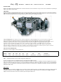
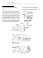
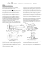
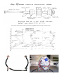
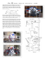
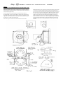
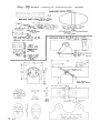
 SECTION
N II LYCO
OMING O 3
320 ENGIINE INSTALLLATION SN JOF
F-67
Enggine Insttallation
n Lyycomingg O‐320 into a Long‐EZ
SECTION
N II LYCO
OMING O 3
320 ENGIINE INSTALLLATION SN JOF
F-67
INTRODUCTIO
ON ection IIL pro
ovides engineering info
ormation an
nd documentation for the installation of any one of various modelss of the Lyco
oming O‐
Se
32
20 aircraft eengine into aa Long‐EZ. HE ENGINE TH
Ass you becom
me more kno
owledgeable about thee Lycoming O‐320 engiine, you`ll soon discove
er that therre are somee model variiations. Th
he commonality of all m
models and dash numb
bers, etc., th
hat makes itt possible to
o cover theiir installatio
on in one manual is thiss: all O‐
32
20's are dim
mensionally ssimilar; the cooling chaaracteristicss are similarr; the cowling fits them
m all; he Lycomingg O‐320 series engines are four‐cyylinder, dire
ect‐drive, ho
orizontally o
opposed, air‐cooled mo
odels. The ccylinders Th
are
e of conven
ntional air‐ccooled consttruction witth heads maade from an
n aluminum
m‐alloy casting and a fully machineed co
ombustion cchamber. Th
he cylinder barrels are machined ffrom chrom
me nickel mo
olybdenum steel forgin
ngs with deeep integral
co
ooling fins, gground and honed to a final speciffied finish. TThe O‐320 sseries engin
nes are equiipped with aa float‐typee carburetor. Particularly ggood distrib
bution of the fuel‐air m
mixture to eaach cylinderr is obtained
d through tthe center‐zzone duction systtem, which is integral w
with the oil sump and is submergeed in oil, en
nsuring a mo
ore uniform
m vaporization of ind
fue
el and aidin
ng in coolingg the oil in tthe sump. In
n addition, the IO‐320 has a fuel in
njector. The
e fuel‐injecttion system schedules
fue
el flow in prroportion to
o airflow. Fuel vaporizaation takes place at thee intake porrts. 20 CUBIC INCH ENGINEE SERIES 32
Acccording to specific enggine model configuratio
on H
HEIGHT WIDTH LENGTH DRY WT
T MODEL R
RATIO H
HP RPM TBO (IN) (IN) (IN) (LBS) REEMARKS O‐‐320‐A 7
7.00:1 15
50 2,700 2,000 2
22.99 32
2.24 2
29.05‐29.81 271‐27
79 Con
nical Mountts OTE: O‐320
0‐A1A Samee as O‐320, model designation chaange only.
NO
In most casess the O‐320 case will be
e machined to accept aa mechanicaal fuel pump. ne more con
nsideration is provision
n on the engine to be aable to instaall an oil coo
oler. A relattively small percentagee of these engines On
maay not be m
machined to
o accept oil ccoolers. Thee original Lo
ong‐EZ N79RA has a Lyycoming O‐2
235‐C2C enggine and is not equippe
ed with oill cooler. On a hot day d
during an exxtended full throttle climb the oil temperature is margin
nally accepttable. We do
o recomme
end the insstallation off oil cooler. MPORTANT IM
he scope of these installation draw
wings does n
not include educating aa home builder in all th
he disciplinees leaned by an A&P m
mechanic Th
to allow him tto work on aircraft enggine installaations. Thuss if you are n
not an A&P mechanic, you should have an A&
&P install yo
our ngine and acccessories o
or at least have an A&P
P inspect an
nd approve tthe work. en
SECTION II LYCOMING O 320 ENGINE INSTALLATION SN JOF-67
STEP 1 INSTALLING THE THROTTLE QUADRANT The throttle quadrant shown is an off‐the‐shelf unit developed and sold by Ken Brock Mfg. We have provided drawings for those of you wanting to homebuilt the Brock unit. Refer to sketches shown here and to page A1, Section I, and locate and mount the throttle quadrant to the instrument panel. Use your dremel to clear a hole through the front seat bulkhead and rear seat bulk head as required. Drill a ½” dia. hole in the firewall as shown on page 13. Run the cables along the left fuselage side at W.L. 11" as shown, routing them through the holes in the bulk heads and firewall. Be sure and deburr the hole in the firewall well. Organize the 3 cables to lay flat against the fuselage side and use short strips of grey tape to hold the cables temporarily in position. You can run the cables over the plywood blocks (L.B, 17 and PT1) that the landing brake and pitch trim handle mount to, or you can route out a groove in these two plywood blocks to get a lower profile and straighter cable run. Now use a small blob of dry micro to bond the cables to the fuselage side and layup one ply of BID over the dry micro and cables. Do this every eight inches or so. Pot the cables generously with RTV (silicone rubber) where they penetrate the firewall for chafe protection and to seal the firewall. Your cables will be too long still; coil them up and tape them to the firewall so they don't get damaged. Do not bend then too sharply. SECTION II LYCOMING O 320 ENGINE INSTALLATION SN JOF-67
STEP II INSTRUMENTATION AND WIRING In this step you will mount your engine instruments, switches and route all of the associated equipment to the firewall. All of the instrumentation called for in this step is available through a Long‐EZ distributor. Recommended Instrumentation: Option 1. Analogical Cylinder Head Temperature Rochester gauge #3070‐61 or VDO #310‐909 Sender #3080‐14 or VDO #323‐701 Oil Temperature Rochester gauge #3070‐62 or VDO #310‐014 Sender #3080‐37 or VDO #323‐057 0il Pressure Rochester gauge #3050‐54 or VDO #350‐044 Sender #3060‐18 or VDO #360‐004 Fuel Pressure Rochester gauge #3050‐58 or any direct Sender #3060‐17 reading pressure gauge Tachometer Carr 2 ¼” #CT42 DS Carr 3” #CT 43 DS First mount your engine instruments positioned as desired on the instrument panel. Any direct reading instruments must have lines at least 10 feet long. A mechanical tachometer is not really practical due to the long heavy cable required. The tachometer recommended above operates electrically through a small tach generator which screws directly to the tach cable mount on the accessory case of your engine. These Tachometers have proven to be reliable and reasonable accurate. A magneto‐powered tachometer can be used, but do be certain that there is no way that a magneto failure could fail one or both magnetos. If you have a starter a standard key‐type on‐left‐right‐both‐start switch works well. Without a starter, two miniature switches (micro 8A1011 or Alco MTF‐106N) mounted as shown on page A1 or where desired, are required. With all these mounted, take your dremel and clear holes through the instrument panel and front and back seat bulkheads (or use the holes cut In Step I). Now drill a ½” hole in the firewall directly below the hole drilled for the control cables (see page 13) and be sure to carefully deburr all sharp edges in the firewall so that they will not chafe your wiring. Now thread your instrumentation wiring, and direct reading lines (if used) through the instrument panel, both seat bulkheads and the firewall. Locate your wiring bundle against the left fuselage side making sure that there is no interference between the pitch trim cables, or the landing brake handle and associated cables. This may require routing the wire bundle through the instrument panel then down towards the floor until aft of the landing brake pivot. Use grey tape strips to temporarily hold the wiring bundle in place, then pot the wire bundle to the fuselage side every 8” or so with RTV (silicone). Do go ahead and include a couple of spare wires in your bundle this can save much grief later on should you decide to install a fuel flow indicator or whatever. Pot the wiring bundle generously with RTV in the firewall. Remember, the wiring bundle will vibrate with the engine and care should be taken to prevent any possibility of the wires being chafed where they come through the firewall. If you have a full electrical system, including starter and alternator you will have a large bundle of wires. It is of course permissible to split the bundle up into two or more, and run half of them down the right side. In this case be sure that there is no possibility of interference with the control system, and bond the wiring bundle to the right fuselage side, preferably in the bottom corner with the fuel lines, using RTV. All wiring should go through the firewall on the left side, so any wiring going down the right side, must be routed across the aft face of the rear seat bulkhead, (in such a way as to not interfere with rudder cables, and aileron torque tubes. Be sure and label each wire, then coil the excess length of the bundle and tape it to the firewall so that it won´t get damaged. If you solder any wires, (magneto switches) be sure and use good quality solder intended for electronics work. SECTION II LYCOMING O 320 ENGINE INSTALLATION SN JOF-67
Option II. Digital System. SkyView SV‐D1000 SkyView Displays utilize TFT active matrix LCD screens and LED backlighting technology for increased life span, more uniform brightness, and reduced power consumption. Buttons and Joysticks: The SkyView System is designed for ease of use while flying. The most used functions are accessed via two rotary/multi‐direction Joysticks, for fast intuitive commands. Almost all other in flight commands, using the widely spaced buttons, are only two button presses away. None or more than three button presses. Redundancy: If two displays are in the system, either one can act as the Primary Flight Display, Moving Map, and Engine Monitor. The unlikely loss of either display will not affect the functionality of the other. System Battery Backup: A system backup battery will provide over an hour of backup power to a Display and Modules. Each Display requires its own Backup Battery for redundancy. Connections: Each display contains: 1 ‐ 37‐Pin DIN Connector for the main wiring harness 2 ‐ 9‐Pin DIN Connector for the SkyView Networks 2 ‐ USB Connectors 1 ‐ Ethernet Connector (currently unused) DETAILED FEATURE LIST
HARDWARE
SV-D1000 10" Display
SV-D700 7" Display
Backup Battery (SV-BAT-320)
ADAHRS - First (SV-ADAHRS-200)
ADAHRS - Additional (SV-ADAHRS-201)
EMS Hardware/Module (SV-EMS-220)
GPS Receiver Puck (SV-GPS-250)
Autopilot Servos
SYSTEM SOFTWARE
Clock - Local
Clock - Zulu
Screen Dimming
Master Power Voltmeter
Internal Battery Voltmeter
Charging Status
Backup/Restore
Measurement Units Setting
Messaging/Alerts
Multiple ADAHRS - Manual Switchover
Multiple ADAHRS - Auto Switchover
EXTERNAL DATA INTERFACES
USB Thumb Drive Firmware Updates
Altitude Encoder
NMEA Input (position, time, speed)
PRIMARY FLIGHT DISPLAYS
Split Screens
Synthetic Vision - Land
Synthetic Vision - Oceans
Synthetic Vision - Lakes
On/Off Toggle (Synthetic Vision - Artificial Horizon)
Airspeed Indicator
Airspeed Trend
Vx/Vy Markers
Altimeter
Vertical Speed Indicator
Artificial Horizon (pitch lines, roll scale, chevrons)
Angle of Attack
Turn Rate
Ball
Compass/Heading
Compass Rose on Horizon
GPS Ground Track Pointer
Outside Air Temperature
True Airspeed
Density Altitude
Flight Path Indicator
ENGINE MONITORING
Flexible Gauge Layout (layout editor)
Flexible Pin Assignments
Tachometer
Manifold Pressure
Tachometer
EGTs
CHTs
GP thermocouple
14 Fully Configurable Thermocouples
Oil Temp
Oil Pressure
Coolant Temp
Coolant Pressure
Fuel Pressure
Ammeter
Voltmeter
Fuel Flow
Fuel Level
Trim Position
Flap Position
SECTION II LYCOMING O 320 ENGINE INSTALLATION SN JOF-67
STEP III INSTALLING THE ENGINE MOUNT Depending of the engine, we will require either a conical or dynafocal engine mount. Both of these are available as welded up, bolt on assembly from Ken Brock Mfg. or others. At this point we will assume we do not have our engine mount aluminum extrusions installed into the fuselage. Cut the “L” shaped holes through the firewall in the correct places. Drill a couple of holes and use a saber saw or a dremeI and pin router. Slide the four 8” long aluminum extrusions into place and verify that they are correctly located with respect to butt lines and water lines. Make the four wood wedges called out on page 14‐4 (section I). Now cut two pieces of the same aluminum extruded angle 1.6" long. Cut some 1/8” thick aluminum sheet into two pieces 1.6" x 2". Carefully examine the full size drawings on this page to familiarize yourself with how the top extrusion mount assembly goes together. You should bolt the 1/8” x 1.6” x 2” pieces of aluminum to the 8” long pieces of extruded angle, and the locate the 1.6” long pieces of extruded angle in the correct position and bolt them into place. You will now have 4 AN509‐10R8 screws bolted into each top engine mount extrusion which when viewed from aft, will look like an upside down 'T'. A 100º countersink is required. Now you are ready to install the extrusions into the fuselage. You should do this "dry" the first time, that is, using dry BID cloth where 10 plies are called for. Install all 4 extrusions and clamp your engine mount into place with "C" clamps. Check the fit of the extrusions and wedges to the longerons, and adjust the number of plies of BID t o obtain a good fit; add whatever plies are necessary, but do not end up with less than 7 plies under each extrusion. When you have an acceptable fit, dry, unclamp the engine mount, remove the top extrusions and dry glass and thoroughly sand the corners between the centersection spar and top longerons. Glue the wood edges in to position using wet flox. Layup the 10 plies of BID (or however many it takes) into each corner, sand the aluminum extrusion completely dull using 220 grit wet or dry. Paint pure epoxy on the extrusions and install them carefully so as not to disrupt the BID glass. Press them gently into place and clamp the engine mount back into position on the top extrusions. If you have done everything right, the top extrusions will now be held in position by the engine mount. Fill any voids under the extrusions, wood wedges, centersection spar, firewall or longerons with flox and allow the whole thing to cure undisturbed. After a minimum of 24 hours, flip the fuselage over and repeat the above for the lower engine mount extrusions, with the exception that the lower extrusions do not get the additional pieces of extruded aluminum angle etc. Allow the lower extrusions to cure with the engine mount clamped in place. This assures you of a perfect fit between the welded engine mount and the aluminum extrusions. Now while the fuselage is upside down, drill the ¼” holes through the extruded angle and center section spar, and short longeron. It is very handy here to have a right angle drill adapter, (the small aircraft type is best and is available from a distributor). A 10” long, ¼” drill bit is required to drill in the engine mount, and works well to reach in to drill through the extrusions and centersection spar. See section I page 14‐4 for bolt hole locations and bolt sizes. Flip the fuselage back cover and drill and bolt up the top engine mount extrusions per Section I page 14‐4. Now remove the engine mount and refer to Section I page 15‐2 Step 3. Note that the full size view AA is not representative and you should use the full size drawing on page 7 of this section. Make one left and one right hand CS73 bracket and install them on the lower engine mount extrusions using one AN509‐10R‐8 screw and one MS21042‐3 nut per bracket as show
SECTION II LYCOMING O 320 ENGINE INSTALLATION SN JOF-67
We are using a conical engine mount, because the Lycoming O320 used on this airplane, require a conical. SECTION
N II LYCO
OMING O 3
320 ENGIINE INSTALLLATION SN JOF
F-67
Insstall the BA b
brake arms onto the uppe
er engine mo
ount extrusions as sho
own. NOTE: tthe BA brakee arm has revversed from tthe original draawings show
w in section I because testting has show
wn considerably better brake efffectiveness tthis way. You
u will need to
o slightly alte
er your Brock BA brake arms tto conform to
o the full sizee pattern below. d of BA as recceived from B
Brock should
d be Alsso the ¼” holle in one end
driilled out to 5/16” dia. No
ow install you
u BA brake arrms on the in
nboard side o
of the upper
engine mount eextrusions. TThe pivot boltts will obviou
usly be too lo
ong at this point sin
nce the engin
ne mount is n
not in place. Temporarily use a sspacer or wasshers in ordeer to rig the b
brake arm, m
master cylinde
er and brake actu
uating cables.. Refer to Secction I page 1
16‐8. ow remove t he pivot boltts (AN4‐14A)) and brake aarms and pussh No
the
e mount into
o position on the aluminu
um extrusions. Space the ends of the mount tubes aft of th
he firewall ap
pproximatelyy 0 .030" and
d unt firmly into
o position on
n the aluminu
um extrusion
ns. claamp the mou
Usse the existing holes in the upper extrusions as drill guides to d
drill thrrough the steeel tubes. Bee very carefull here, it is veery easy to have the
e drill wandeer off and elo
ongate the ho
oles. Best pro
ocedure is to
o drill the
e holes undeersized, then drill or ream
m them up to size. Drill two ¼” ho
oles per extru
usion as show
wn. Use your long drill bitt to drill the ho
orizontal holees, due to drill motor cleaarance. Installl AN4‐14A bo
olts thrrough the up
pper extrusio
ons and brake
e arms (don'tt forget the C
CS75 ste
eel bushings)) use AN4‐13A bolts verticcally through
h both upperr and low
wer extrusion
ns and AN4‐ 12A horizonttally through
h the lower exttrusions. Usee AN960‐416
6 washers as required and
d MSS21042∙4 nuts. SECTION II LYCOMING O 320 ENGINE INSTALLATION SN JOF-67
STEP IV INSTALLING THE CARBURETOR AIR FILTER AND HEAT VALVE. Before proceeding with air filter installation, if you do not have the CS123 bushing and CS124 belhorn installed, you should install them now (section 1 page 16‐ 5). You can obtain an air filter from your local auto parts store. A Purolator #AFP‐117 or and A.C. 448C or similar filter will work fine. See page and locate your filter as low as far right as possible on the right side of the firewall. Be sure that there is no interference with brake lines or rudder cable or belcrank. Use a felt tip pen and mark around the filter then set it aside. Next fabricate the carb. heat and air valve shown below and on page 9. This part is available prefabricated from Ken Brock Mfg. Locate your air valve over the outline you marked of the air filter so that the four corners over hang it roughly equally. Mark the location of each corner on the firewall. Check again for possible interference with brake line or cables. Drill two small holes (1/16"dia.) through the firewall and make a loop of .0 41” stainless safety wire through the holes as shown, at each corner. Cut four lengths of 3/8” screen door spring and install the air filter and valve assembly with the springs holding the valve and air filter tightly against the firewall at all four corners. SECTION II LYCOMING O 320 ENGINE INSTALLATION SN JOF-67
SECTION II LYCOMING O 320 ENGINE INSTALLATION SN JOF-67
STEP V INSTALLING THE GASCOLATOR, ELECTRIC FUEL PUMP AND OPTIONAL CABIN HEAT VALVE. These two bolts will be accessible from inside the Carefully examine page 13. This drawing is not to scale but centersection spar box. Plumb the electric pump to the outlet clearly shows where to position the above parts on the of the gascolator with 3/8" dia soft aluminum tube. This tube firewall. Disregard the drawing showing position of must be bent such that it clears the aileron pushrod. It can gascolator, fuel pump and wire bundle on page 21‐8 Section 1, although the method of mounting the gascolator is the not pass between the aileron pushrod and the firewall, but rather should curve away from the firewall to pass aft of the same. aileron pushrod. Note: the EFP fuel pump is drilled and The gascolator is hung from the firewall such that you can tapped with a 1/8" pipe thread, as is the Bendix fuel pump, easily reaching through the cooling air scoop, and drain the and you will require two special elbows, AN822‐6‐2D which gascolator during pre‐flight inspection. The 3/8” dia. are available from a Long‐EZ distributor. Plumb from the aluminum fuel line from the center of your fuel valve, see electric boost pump to the mechanical pump on the engine section I page 21‐ 5, should come through the firewall, just to using aeroquip flexible hose. #303 hose #491 hose fittings are the right of the throttle, carb, heat and mixture cables. Drill a called out, but you can substitute aeroquip # 601 hose and ½” dia. Hole through the firewall, push the fuel line through. #816 fittings. Pot the fuel line generously into the ½” hole with RTV silicone rubber. Mount the gascolator as shown on page 13 using two At this time you can mount the optional cabin heat valve AN822‐6D elbows screwed into the gascolator, two clamps, available from Ken Brock Mfg. or you can easily build one yourself from the information on page 9. Be very careful not MS21919‐DG11, two AN3‐17A bolts with AN960‐10L washers to drill in to the lower centersection spar cap, when mounting and MS21042‐3 nuts and two 3/8 O.D. x 3/16” I.D. and 1” this valve. A good method of mounting the valve is to glue it long spacers. Be sure to orient the gascolator correctly for fuel flow (in vs. out). to the firewall with RTV silicone. If your engine has an MA3 carburetor it will not have a built in STEP VI MOUNTING THE ENGINE accelerator pump. The MA‐3 SPA carburetor has the pump. Without an accelerator pump, particularly in cold climates, With the exception of the hardware, mounting the conical or the engine can be very difficult to start. This can be remedied dynafocal engine is essentially the same. You will require an by installing a primer. The primer pump should be installed on the instrument panel if you intend to hand prop‐start. Fuel engine hoist, or a block and tackle from a rafter, or several for the primer should be taken from the top of the gascolator strong friends. using an AN816‐20. 1/8" dia. soft copper tube should be used and you should drill a ¼” dia. hole through the firewall and Load the front cockpit with ballast so that the airplane does pot the 1/ 8" copper line in RTV silicone rubber. not tip over when you mount the engine. Hoist the engine into position on the mount and hold it there. All four shock The electric boost pump is required on your Long‐EZ and mounts, bolts and nuts are now installed. Be careful not to should under no circumstances be omitted. Mount it where bash the engine or accessories against the mount, particularly shown on page 13 using two AN3‐10A bolts, AN960‐10L the mechanical fuel pump. As you fit the engine up to the washers and MS21042‐3 nuts. If you cut out the oval shape lightening hole in the plywood firewall bulkhead, you will mount support the engine weight until all four bolts and nuts need to position a small piece of plywood in the void in the are torqued up. Torque requirements are: area where these two bolts go to secure the electric fuel 3/8" ‐ 24 bolts (conical mount) 220 to 320 inch pounds. pump. Be careful not to drill trough the firewall into your 7/16” – 24 bolts (dynafocal mount) 430 to 580 inch pounds. centersection spar cap! That would spoil your entire day. Note: or you can substitute a Brock vely 13 FLANGECAUTION Make certain that the outer cord and inner wire are both trapped under worm gear clamp exactly as shown. If this is not done the wire can unwind and collapse resulting in engine failure.
SECTION II LYCOMING O 320 ENGINE INSTALLATION SN JOF-67
STEP VII AIR INDUCTION SYSTEM This page shows details on how to make the carburetor inlet elbow. This elbow will bolt to the inlet flange on the bottom of the carb. A gasket should be used, or sealant that is fuel proof (not RTV silicone). When you build the fiberglass elbow, be sure it is oriented correctly to point forward at the carb air/heat valve. Next mount a length of CAT‐10 (or SCAT‐10) to the elbow. Pay careful attention to the clamping details shown. Do not substitute ceet or sceet hose. Route the inlet hose to the bottom of the carb air/heat valve and clamp it in place. The inlet how should not be stretched tight. A little slack is required to allow for engine shake during operation. Drill a ¼” dia. Hole in the low point (nose gear retracted with no electric starter, and 3 point with a starter) of the air inlet how to allow excess fuel to drain for a flooded start. To make this: 1) Carve a urethane foam block in the correct shape with the sanded 2.5” tube stuck over one end. 2) Mount the block on a flat surface covered with duct tape (release). 3) Layup the 4 plies BID overall, over‐
lapping small pieces is ok. 4) After cure dig out the foam and drill 1/4” holes. SECTION II LYCOMING O 320 ENGINE INSTALLATION SN JOF-67
SECTION II LYCOMING O 320 ENGINE INSTALLATION SN JOF-67
STEP VII ENGINE WIRING AND CONTROLS It is helpful to have an assistant to verify control positions and travel in the cockpit, while you work on the engine. First make all the metal parts shown (page 16). Install the throttle/mixture bracket on carb studs. This bracket becomes a "gasket" between the carb and engine, and requires two normal gaskets (one each side), when installing the carb. The small tab on the aft end of the bracket should be bolted to a .063 x .6 alum strap. The strap should be bolted to an oil pan bolt. Apply additional damping by bonding the bracket to the oil pan with silicone rubber (RTV). Next run your mixture/throttle cable out and around to the right and mount to the bracket as shown. Be sure the clamps aim the cables directly at the actuated arm, with as little flexing as possible. The controls must work without the return springs. Check this before installing the springs. The springs take all of the "slop" out of the system for smooth throttle and mixture control, but do not depend on the springs. The springs will return the throttle to full open and mixture to full rich In the event of a cable failure. Mark the cable housing to be trimmed so that it protrudes about ½” beyond the housing t clamp. Before you try cutting the cable housing to final length try a practice cut way out on the end of the housing. The idea is to use your dremel (stone grinding wheel) to grind part way through the housing wire, not into the cable (see sketch), and then break the wire with a twist (using pliers). Don't damage the cable inside. With the housing cut to length you can use your dikes to cut the cable. Be sure you have enough extra cable to make a loop around the AN111‐4 thimble. Install the mixture arm bracket on the carburetor mixture as shown: Clamp the cable between your thumb and finger and verify that you have full mixture travel at the carburetor when the mixture control is cycled in the cockpit before you swage the sleeve. If you don't get it perfect an adjustment can be made at the housing clamp. Tighten the bolts on the cable housing clamp. Add a dab of silicone rubber over the cut end of the cable; it will save sane pain and expletives later. The throttle cable is installed in a fashion similar to t he mixture. A Centry Spring Corp. C‐161 spring is used to preload the throttle in the full (open) position (see photo). The throttle cable is swaged with an AN111‐4 cable bushing and 18‐
1‐C sleeve as s own. The cable is attached to the throttle arm with an AN3‐7A bolt 3/16 ID x ¼ OD X .25 long spacer, AN970‐3 washer, and MS21042‐3 nut as shown in the sketch. The AN111‐4 must rotate freely on tile spacer. Double check the throttle travel in the cockpit and at the carburetor before swaging. Dab the cut cable end with silicone rubber. The carburetor heat cable housing damp, cable, and return spring are installed as shown on page 8. Don't force the cable and housing around tight corners; leave enough slack for a gently loop to the cable housing clamp. Next attach each magneto ground to the electrical wires running forward to the mag switches. A schematic diagram is shown for the installation of mag wiring below, Connect the switches to the aircraft ground as shown. Connect the aircraft ground wire to one of the engine mount bolts. Install a short length of braded strap from the mount to a convenient stud on the engine . Install your CHT probe on the number 4 cylinder, top side. During your initial runs and initial flights you should move the probe to other cylinders. Once the hottest cylinder is determined, leave the probe in it. All cylinders on N79RA run within 20ºF of each other. If you have a wide variation the probable cause is mixture distribution. Follow your engine service manual and route the ignition wiring (spark plug leads) to each plug. Snug the plug caps (shielded harness only) using a ¾” wrench; don't over tighten. Be sure to guard the ignition wires against chaffing on the cylinder cooling baffles using rubber grommet as shown. The exhaust gas temp probe should be installed on number 4 cylinder exhaust pipe. SECTION II LYCOMING O 320 ENGINE INSTALLATION SN JOF-67
Oil pressure sender: Install as shown. The sender mounts to an engine mount tube using two Adel‐type clamps (MSS21919‐DG10), bolted together – one around mount tube and one around the AN910‐1D coupling. The orifice fitting is normally supplied with the engine. It has a tiny hole, which prevents massive oil loss in the event of hoze or sender failure. Photo of carb and carb controls bracket. View from aft, looking forward. Note: The throttle clamp block is too far to the left on this photo. Make yours exactly per page 16 to assure positive throttle actuation in the event of spring failure. Note: The black plastic does not go into the clamp blocks. STEP IX COWLING INSTALLATION Long‐EZ cowling halves are available from Long‐EZ distributor. These parts will require some additional work as part of the installation on your airplane. You will have to trim the outboard ends of the cowling halves to fit the wing roots; layup a closet rib in the trailing edge of the cowling; layup fiberglass attaching flange along the centersection spar, fuselage and wing roots and attach the ram air inlet to the lower cowl. You will also fabricate a sheet metal oil check door, and install the upper baffle ribs. The cowling is attached to the airplane with #10‐32 screws (AN507‐
1032R10), nut plates (K1000‐3) and countersunk washers (A3235‐
028‐24A). Camloc fasteners may be substituted as a quick disconnect feature along the wing roots, top, bottom and along the cowling trailing edges. Camlocs along the centersection spar and fuselage are not recommended due to the requirement to physically remove the camloc before the cowling can be pulled out from under the attach lip. Dzuz type fasteners should not be used as t hey do not provide adequate shear load‐carrying capability. The vendor supplied cowling halves are intentionally supplied a little too wide. Hold your cowling in position against the firewall aft edge of the center section spar and mark along the wing roots. It is much easier to install the cowling with both wings mounted on the aircraft and with the engine mounted and spinner at least located on the prop flange. Trim the cowl span wise to fit. Now sand the inside trailing edge of the top cowl half, and apply shiny surface grey duct tape on the inside trailing edge of the bottom cowl as shown. Jig your cowling on the floor, trailing edge down, with the trailing edge taped together with grey duct tape and the leading edges opened apart 8 ½” as shown. Cut 10 strips of 45º BID glass 4" wide x 15” long, and 2 strips of BID glass 3" wide X 15”" long. Now layup a 5 ply BID glass rib into the trailing edges of the Cowling. Allow this to cure, then drill 3 #30 dia holes evenly spaced along each trailing edge, through the bottom cowl, grey duct tape and cured trailing edge rib. These holes will be used to cleco the cowl valve s together when jigging the cowling to the fuselage. Later on they will be opened up for screws or camlocs. Now pop the two cowling halves apart and sand the 5 ply closeout rib and top of the top cowl and layup 1 ply of BID as shown. After cure, trim the closeout rib to 1.6 " as shown. Thoroughly sand the top and bottom aft edges of the centersection spar, also around t he aft edge of the fuselage. Sand inside the wing roots, top and bottom. Cut some short pieces of 2x2 lumber about 2 ½” long. Bond these to the aft face of the centersection spar, and fuselage both top and bottom edges as shown. Spacing should be the same as the screws or camlocs, approximately 9 blocks along the top cowl and 10 blocks along the bottom cowl. Position these blocks so that the cowl lip rests on the blocks, the lip is level with the spar or fuselage as shown. SECTION II LYCOMING O 320 ENGINE INSTALLATION SN JOF-67
Now lay up 5 ply BID flanges across the center section/fuselage as well as under the top cowl out board ends, into the wing roots. This last layup is an upside down operation, but is easy to do, particularly if you do the 5 ply layup off the airplane on a piece of visqueen (plastic) first, then while it is wet, lift the visqueen and 5 ply layup and place it in position under the cowl edge, lapping under the edge of the wing root. Squeegee it well through the visqueen and allow ure. The plastic will easily peel off later. Apply a strip of grey duct tape to the inside surface of the outboard edges of the top cowl. This will allow you to release the cowl edges from the glass attach flanges in the wing roots. Remove the exhaust system, if installed, and with the spinner in place, jig the cowling into position, such that the spinner roughly centered in the trailing edge opening. If you intend using starter the ring gear should be positioned so that you have no less than 0. 4" clearance between the top cowl and the teeth on the starter ring gear. The cowling trailing edges should match pretty close to the wing root trailing edges. The cowl leading edge lips should rest on your wood blocks. Drill #30 dia holes through the leading edge lip of the top cowl into the wood blocks. Space and position these holes so that they can later be enlarged and used for the 10‐ 32 screws to attach the cowling. Remove the bottom cowl, lift the top cowl and put a small blob of Bondo on each wood block and cleco the top cowl into position. When the Bondo hardens, remove the clecos, and apply a strip of grey duct tape to the leading edge lip of the cowling. This will allow you to release the cowl after you have layed up the cowl attach flange. Position the outboard edges of the top cowl so that they accurately follow the contour of the wing roots. Locate the top cowl edges in this position by glueing popsicle sticks across the wing root/ cowl joint with small dabs of Bondo.
When all top flanges are cured, drill 130 #holes through the flanges and cowling where you will later on install screws or camlocs. Thi s will allow you to cleco the top cowl back into exactly the position it is in now, after you have removed it. Knock the 2” x 2" wood blocks off the centersection and fuselage and remove the top cowl. Repeat all of the above and lay up the flanges around the bottom cowl. This entire operation can be done without turning the airplane over. If your work area does not allow you to install both wings at the same time, you can install one wing, lay up the wing root flanges for top and bottom cowls, remove that wing, then install the other wing and do the wing root flange layups on it. It is a big help to Bondo a rib to the aft face of the centersection spar, to define accurately, the wing root trailing edge, of the wing that will not be installed while you are installing the cowling. Be careful when you are removing the cowling halves, not to peel the flanges up off of the spar, fuselage or wing roots. With both cowl halves off the airplane you need to layup one ply of BID under each flange, laping down onto the spar or wing as shown. Of course you must thoroughly sand the shiny surface under the flanges and wipe a small amount of dry micro into the corners to give a smooth transition as shown (or better yet use peel ply before the 5‐ply layup). When everything has cured, trim all rough or sharp edges, and drill out the #30 holes to #10 for AN507 screws along the leading edges of the cowling and install K1000‐3 nut plate s on the inside of the cowling lips. Install screws or optional camloc along the outboard edges and trailing edges of the cowling. Camloc part numbers are as follows: Stud ‐ #4002‐6 or #4002‐7 (depends on thickness of your cowling lip and flange). Grommet #4002‐N, grommet retaining Snap ring #R4G, receptacle #214‐ 16N SECTION II LYCOMING O 320 ENGINE INSTALLATION SN JOF-67
Some builders may have a VariEze cowling or a real early production Long‐EZ cowling. If you do, it can be used on your Long‐EZ. The cowling on the prototype N79RA is a VariEze cowling. In order to find out which cowling you may have, measure the length of the top cowl along the centerline as show STEP X OIL CHECK DOOR You will need to fabricate a door from .032 thick 2024‐T3 aluminum sheet to fit into the recess provided in the distributor supplied cowling. This door is attached to the cowl along its lower edge with 3" long aluminum hinge. One half of the hinge should be reversed to make up the difference in thickness of the cowl and door as shown. Note that the supplied cowling is reinforced around the area for the oil check door. You will cut out the center of the recessed area leaving a ¼” lip all around, with the exception of the lower edge, where the ¼” lip must be removed locally to clear the hinge, a Dzus type fastener should be used to hold the door closed. The VariEze and early Long‐EZ cowl is 32". The new Long‐EZ cowl manufactured after December 20th, 1980 is 32.7". The VariEze cowl is also approximately 9" wider than it needs to be for a Long‐EZ, This means that it will be necessary to reinforce this area for screw or camloc mounting. Sand the inside face and layup 4 ply BID reinforcement on the inside of the cowling halves,2” wide and 4 places as shown. After this cure, trim approximately 9” excess off the outboard ends to fit your wing roots. With the old style shorter cowling it will be necessary to space the cowl halves 0.7” aft of the firewall and centersection spar. Use wood bloc k, Bondo' ed to the aircraft, t hick enough to extend aft far enough so that you can cleco the cowl to the aircraft, see photos on page 35. After the cowl is jigged and cleco´ed in to place, the 0.7" gap should be filled between the wood blocks with scraps of urethane foam. These can be jammed into the gap and sanded level with the cowl lip. Then cover the urethane foam and excess wood blocks with shiny grey duct tape for a good release. Now do the layups as called out above for the Long‐EZ cowl, including the inside lip t o centersection layup (Pg. 18 & 19) SECTION II LYCOMING O 320 ENGINE INSTALLATION SN JOF-67
STEP XI COOLING BAFFLES We have provided full size pattern drawings to assist you to make the baffles to direct cooling air to the cylinders on your engine. These drawings are on pages 22‐29. Note that for the forward and aft baffles, you will need to glue 3 pages together to get the full size baffle due to paper size. While it is possible to make these two baffles in one piece, you would find it much easier to fabricate them in 2 or 3 pieces. Join them at the narrowest point by a allowing some extra material (0.6"), overlapping and riveting them together with no prop rivets. The baffles are bolted to the engine wherever a hole is shown and further secured in place by applying a generous bead of RTV silicone (the red or silver high temp RTV is best and is generally available at auto parts stores) along the edges of the baffles wherever they touch the engine, or to seal imperfect fits, and as an anti‐chafing material. Fabricate all the baffles shown, using .025" thick 6061‐T6 aluminum sheet. The inter cylinder baffles are fitted into place and secures in addition to high temp RTV, by safety wiring them down to the stiff piece of music wire which is bent and fitted between cooling fins as shown. With all engine baffling in place, install the cowling one half at a time, and measure the distance from, the top of the aluminum baffles to the cowl. This dimension should be from ¼” to ¾” except along the cylinder head baffles where it should be ¾” to 1 ¼”. Make up neoprene asbestos strips as shown in the photos and rivet them to the aluminum baffles as shown. With the top cowl in place, mark the inside surface of the cowl adjacent to the outboard edge of the cylinder head baffles. This mark will help you locate the two glass "baffles" that have to be lay up into the top cowl. See page 22 for full size templates for these baffles. Lay these out on a piece of 1/8” plywood, or something similar, cut them out and stick grey duct tape to the out board faces of the plywood. Now Bondo these pieces into the top cowl, along your marks. When the Bondo is hard, trial fit the top cowl to be sure the neoprene asbestos cylinder head baffles rest nicely against the grey duct tape on the plywood. Remove the top cowl and sand the inside adjacent to the grey duct tape. Layup 2 plies of BID at 451 and allow to cure. Knife trim to the edge of the plywood at the appropriate time and allow to cure. Carefully remove the plywood pieces and sand the shiny surface of the glass rib, and adjacent to it on the cowling. Layup 2 plies of BID at 45°. Knife trim to the previous glass layup and cure. This gives you two permanent fiberglass “ribs” in the top cowl that the cylinder head baffles seal against, which allows you to remove the rocker covers for periodic maintenance, without disturbing the baffling. With all the baffling in place, carefully check for any potential leaks. Al l possible leaks should be sealed or you may have unacceptably high cylinder head temperatures.
Now install the exhaust system available from Ken Brock Mfg. and measure from the wing root trailing edge to the exhaust pipe each side. Transfer that to the bottom cowl and cut out a hole large enough to clear the exhaust with aluminum of ¼” around the pipe to allow for engine shake. STEP XII OIL COOLER The prototype N97RA does not have an oil cooler installed. During a full power climb to 12.000 ft the oil temperature will climb almost to the red line. During cruise flight oil temp runs between 200º and 220º which is marginally acceptable. A second Long‐EZ with a flush NACA inlet was found to be unacceptable for oil temp‐temperature, although cylinder head temperature was excellent. This air plane has been equipped with an oil cooler which is simply bolted to the lower cowling on the left side, and a 2 ½” dia. Hole was cut through the cowling directly under the oil cooler. This allows high pressure cooling air to escape through the oil cooler. A small reverse scoop, fabricated by laying up 3 plies of BID over a carved piece of urethane foam, is riveted to the bottom cowl. This system provides good oil cooling, (180º ‐ 200ºF) at cruise and 220º‐230ºF in a long climb. Of course the 2 ½” dia opening can be varied to suit. People living in extreme climates may need a large opening in summer, and smaller or completely sealed opening in winter. FINISHING UP Install your prop, 3" prop extension and spinner. Follow the instructions supplied by the manufacturer. Do not install a prop extension without drive lugs to locate in the forward face of the prop. Proper torquing of your prop bolts is important. The prop is driven mainly by the friction developed between the prop hub and the engine flange or prop extension. Extensive testing has shown that wood props generally should be compressed about 0 ,006" per inch of hub thickness. That is to say that a Long‐EZ prop, normally about 3 ¾” thick at the hub, should have the bolts torque up such that the wood in the hub is compressed 3.75” x .006” = .0225”. Since your prop bolts are 3/75" x 24 threads, you can readily figure that you must turn each bolt .54 of a turn after the front face plate, the prop hub and the prop extension flange are in contact. (.0225" x 24 = 0.54 turns) the difficulty here is in knowing exactly when the prop and flanges are in contact, particularly if you have bolts that are tight in their holes. Generally you can achieve the same prop hub compression, assuming your threads are clean, and dry, and in good condition, by torquing your 3/8” dia bolts to approximately 200 inch lbs. (± 25 inch lbs.) Caution: over‐tightening prop attaching bolts will cause the wood in the hub area to crush. This could crack the finish and allow moisture, to enter the wood and will reduce the drive‐torque capacity of the installation. Check “track” of the blade tips by rotating the prop past a fixed object mounted on the floor. Prop tips must track within 1/16” of each other when the installation is completed. Protect your prop by waxing with a good quality paste wax, and place prop in a horizontal position when parked. Inspect and check prop bolts for tightness at least every 100 hours or annually. More frequent inspection may be necessary when climate changes are extreme. Properly cared for, your wood propeller is a safe and reliable part of your airplane. SECTION II LYCOMING O 320 ENGINE INSTALLATION SN JOF-67
SECTION II LYCOMING O 320 ENGINE INSTALLATION SN JOF-67
SECTION II LYCOMING O 320 ENGINE INSTALLATION SN JOF-67
SECTION II LYCOMING O 320 ENGINE INSTALLATION SN JOF-67
SECTION II LYCOMING O 320 ENGINE INSTALLATION SN JOF-67
SECTION II LYCOMING O 320 ENGINE INSTALLATION SN JOF-67
SECTION II LYCOMING O 320 ENGINE INSTALLATION SN JOF-67
SECTION II LYCOMING O 320 ENGINE INSTALLATION SN JOF-67
SECTION II LYCOMING O 320 ENGINE INSTALLATION SN JOF-67
SECTION II LYCOMING O 320 ENGINE INSTALLATION SN JOF-67
The carb/cabin heat exchanger shown on pg. 33 is available as an integral part of your Long‐EZ exhaust system Ken Brock Mfg. sells these parts and they are welded up on the exhaust and pressure checked for leaks prior to being sold. If you intend using the heat exchanger to provide heat in the cockpit it is absolutely mandatory that you install a fresh air ram scoop in the lower right cowling and connect it to the aft 2"dia tube on the heat exchanger. This clean cold air then is heated up by the hot exhaust and is forced forward by ram pressure through a length of 'scat', red high temperature aero duct hose to the carb air/heat valve as shown. This is the source of carb heat if or when required. If you decide to install the optional cabin heat valve as shown on page 9, you should cut a 1 ½” dia hole in the carb air/heat valve and install a short 1 ½” dia tube, welded or sealed as shown. This is connected to the cabin heat valve with 'cat' black aero duct hose. Thus, you have a clean source of hot air for the cockpit. If you decide to home build this heat exchanger it is very important that no carbon monoxide can get into the cockpit. Fresh, clean air must be brought into the heat exchanger, do not use the high pressure cooling air in the cowling for cabin heat. This air could easily be contaminated by any small exhaust gasket leak or undetected exhaust leak. Because the possibility always exists of carbon monoxide getting into the system, it is highly recommended that you install a carbon monoxide indicator in the cockpit. Route a 1 ½” dia 'cat' aero duct hose from the cabin heat valve forward across the aft face of the back seat bulkhead to the right side of the fuselage. This hose should run forward along the fuselage side to the instrument panel. Be sure to secure the hose so that it does not interfere with the control sticks, pushrods, etc. Do not allow this hose to come into contact with the fuel lines, which also run up the right side. Allow a minimum of ½” clearance between the hose and the fuel lines. SECTION II LYCOMING O 320 ENGINE INSTALLATION SN JOF-67
SECTION II LYCOMING O 320 ENGINE INSTALLATION SN JOF-67
Baffles before installing neoprene lips. Note lip to seal around alternator and silicone sealant. Note Exhaust support attached to the baffle bolt. Breather: Bond a flattened ¾” alum tube to cowl stiffener. Attach a ¾” I.D. x 1/8 wall tygon plastic tube from it to the breather.
SECTION II LYCOMING O 320 ENGINE INSTALLATION SN JOF-67
Jigging cowl to fuselage and centersection spar, using clecos and wood blocks. If cowl does not fit satisfactorily it can generally be urged into place after application of heat from a hair dryer or industrial heat gun. Use these photos to determine spacing of screws and cowl flanges (approx. 16 top cowl and 24 bottom cowl), note the 4 screws and exit scoop for optional oil cooler installation. The oil cooler is held in place by 4 # 10 screws & nutplates. The exit scoop is held on the cowl with 4 pop rivets. This photo shows installation of mixture arm cable and return spring.
This photo shows installation of mixture arm cable and return spring, fiberglass carb inlet elbow and fuel pressure sender
Note sliced neoprene baffle lip, and carb heat hose routing. This hose is bound to the engine mount using a 1” wide strip of neoprene asbestos material to prevent the safety wire from cutting into the hose Oil cooler on left side. Note K‐1000‐32 nut plates installed with rivets. SECTION II LYCOMING O 320 ENGINE INSTALLATION SN JOF-67
SECTION II LYCOMING O 320 ENGINE INSTALLATION SN JOF-67
BILL OF MATERIALS 1 Micro switch type V3 or Radio Shack 275‐1102 6 AN3‐7A Bolts 2 AN3‐14A Bolts Engine Mount Hardware 2 AN4‐12A Bolts 4 AN4‐13A Bolts For Conical Mount: 2 AN4‐14A Bolts 4 AN6‐43A Bolts 18 MS21042‐ 3 Nuts 4 AN960‐616 washhers 8 MS21042‐3 Nuts 4 Lyc. # std 619 Washers 10 AN509‐10R8 Screws 4 AN363‐624 Nuts 2 AN111‐4 Cable bushings 8 #71032 Rubber Bushings. *3 AN818‐2D Nuts *3 AN819‐2D Sleeves OR 6 AN818‐6D Nuts 6 AN819‐6D Sleeves For Dynafocal Mount: *2 AN822‐2D Elbows 4 AN7‐35 A Bolts 4 AN822‐6D Elbows 8 AN960‐7616 Washers 2 AN822‐6‐2D Elbows 4 AN363‐720 Nuts **2 AN822‐6‐6D Elbows 8 Dynafocal Bushings *1 AN816‐2D Nipple (for 2 3/4" I.D. Retainer) 1 AN816‐4D Nipple 4 Steel Spacers. 2 ANB16‐60 Nipples 4 AN823‐6D Elbows Baffle Material 1 AN910‐1D Coupling 5" of 1/8" x 1" x 1 1/2" 2024 T3 Alum Angle 1 AN912‐1D Bushing 1 pc. .025 – 6061T6 Alum Sheet 30" x 48" 1 3600 x 4 Weather‐ Head Male Branch Tee. 2AC #6470069 Adapters 1 pc. 1/16" x 12" x 40" Neoprene ‐ Asbestos 2 Aeroquip491‐4 Fittings 200 Avex 1601‐0410 Pop rivets 4 Aeroquip 491‐6 Fittings (**8) 200 AN960‐4L Flat Washes. 33" Aeroquip 303‐6 Hose (**84”) 12 AN500‐A416‐10 Baffle Screws 6" Aeroquip 303‐4 Hose 12 AN936‐A416 Lock Washers 2 AN931‐6‐16 Rubber Grommets 4 Blow proof exhaust gaskets Lyc. #77611 48" of 2 1/2" dia. 'Scat' aeroduct 8 Lock Washers MS 35333‐41 12" of 2" dia. 'Scat' (optional cabin heat) 8 Exhaust Manifold Nuts Std. 1410 5116 ‐ 18 Lyc. 12" of 1 1/2" dia. 'Cat' (optional cabin heat) 18" ‐ 3/8" 0.D. x .035 wall 4130N steel tube. 4 Stainless worm clamps #136 ( 2 1/2" dia.) 18" ‐ 3/4" 1.D. x 1/8” wall tygon plastic tube. 6" ‐ 3/4" 0.D . x .049 wall 6061‐T6 alum. tube. 2 each #CS springs (1/2" long x .35" 0.D. x .06 wire compression). 8" ‐ 3/16" x 3/4 " 2024T3 alum. bar. 2 each Century #C‐161 Springs. 24 Nylon ty‐raps (6"long) TY‐525M 24 Nylon ty‐raps (12" long) TY‐528M 1 tube high temp RTV (silicone) (red or silver) Optional ** Only required if an oil cooler is used. *1 Essex Primer #K2404‐1/8" * Only required if a primer is used. ** 1 Harrison Oil Cooler P/N 8526250 Electrical Brock – Supplied Components Carb heat – mixture – throttle quadrant assy. Long‐EZ Spinner VESPI Prop Plate KM01068 3‐ inch Prop Extension KM06018 Exhaust System with heat muff BJX‐IHM Cabin heat valve (optional) Carb. heat valve assy. VECHVA Electric fuel pump EFP Carb. Heat flange (optional) VELY13 Long‐EZ Lyc. O‐320 Conical engine mount. 2 Steel Bushings LL‐3 2 Alum Bushings LL‐4