1
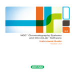
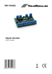
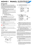
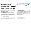
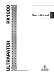
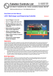
D-27
9/26/07
8:57 AM
Page 1
Bulletin D-27
Series WWDP Wet-to-Wet Differential Pressure Transducers
Specifications - Installation and Operating Instructions
6
[152.4]
2
[50.5]
5-9/16
[141.29]
R7/64
[R2.78]
4-39/64
[117.08]
11/32
[8.73]
4-53/64
[122.63]
4
[101.6]
2
[50.8]
1-15/64
[31.35]
1-43/64
[42.47]
5-11/64
[131.37]
1/8” NPTF
1-9/16
[39.69]
61/64
[24.21]
1/2” CONDUIT
OPENING
The Series WWDP Wet-to-Wet Differential Pressure Transducer
offers everything in one package by having 30 field selectable variations in
just 3 models. The WWDP provides field selectable unidirectional and
bidirectional pressure ranges, configurable 0-5, 1-5, 0-10 VDC, and 4 to
20 mA output. It also provides an auto-zero capability. The field selectable
port swap feature eliminates costly replumbing if the unit is improperly
installed or if the transducer is simply replaced. An optional LCD display is
available for on-site indication of line and differential pressure. The all cast
aluminum housing is rated NEMA 4 (IP66). These features make the
WWDP transducer an ideal instrument for measuring the flow of various
liquids and gases, pressure drop across filters, measurement of liquid level
or pressurized vessels, and for use in energy management and process
control systems.
INSTALLATION
The Series WWDP Wet-to-Wet Differential Pressure Transducer has 1/8”
NPTF internal fittings. The high pressure port and low pressure port are
located on the bottom of the unit, labeled “HI” and “LO”, respectively.
MOISTURE PRECAUTIONS
The Series WWDP is provided with a 0.875 DIA. conduit opening for
electrical termination, intended for a 1/2” I.D. conduit connection. This
opening must be sealed according to standard industry practices in order
to prevent moisture ingress into the Series WWDP.
MOUNTING
The Series WWDP can be easily mounted using the two mounting screws
located on the side of the unit.
INSTALLATION PROCEDURES
For differential pressure measurements at high line pressure, it is
recommended that the pressure sensor be installed with a valve in each
line, plus a shunt valve across the high and low (reference) pressure ports
as shown in Figure 1.
The remote zero is a normally open relay wired between COM and
REMOTE ZERO terminals. In order to initiate ZERO function, the relay
contact shall be closed.
Important: Do not exceed maximum range pressure with a total of
differential pressure and line pressure.
SPECIFICATIONS
Service: Gases or liquids compatible with 17-4 PH stainless steel.
Accuracy: All pressure ranges have ±1% full scale accuracy except the
lowest selectable range of each unit is ±2% full scale.
Stability: ±0.5% per year.
Temperature Limits: Compensated Temperature Range: 32 to 130˚F
(0 to 54˚C); Operating Temperature Range: -4 to 185˚F (-20 to 85˚C).
Pressure Limits: Max working pressure: WWDP-1: 50 PSI; WWDP-2:
100 PSI; WWDP-3: 250 PSI; Proof Pressure: 2.2X of full scale; Burst
Pressure: 40X of full scale.
Thermal Effect: 2% FS/100˚F (50˚C) includes zero and span.
Power Requirements: 12 to 30 VDC/18 to 28 VAC (Reverse Excitation
Protected). NOTE: 4-20 mA output cannot be powered with AC voltage.
Output Signal: Selectable 0-5, 0-10 and 1-5 VDC; 4 to 20 mA.
Zero & Span: Digital “re” zero button (should be used when changing
ranges). Span can be adjusted by changing between field selectable ranges.
Response Time: 1 to 5 sec (selectable).
Loop Resistance: 1000 ohms.
Current Consumption: VDC power: 0-5, 1-5 VDC output 4 mA (typ); 010 VDC output 5 mA (typ); 4-20 mA output 20 mA max. Current
Consumption will equal the transmitter output in current mode. VAC
power: 0-5, 1-5, 0-10 VDC output 40 mA (typ).
Electrical Connections: 1/2” Conduit.
Process Connections: 1/8” Female NPT Internal.
Enclosure Rating: Designed to meet NEMA 4 (IP66).
Mounting Orientation: Vertical; Mount the pressure ports down (keeps
debris from building up inside the pressure port).
Size: 4 x 6 x 2 in (102 x 152 x 51 mm).
Weight: 1.5 lb (680.4 gm).
Agency Approvals: CE.
Low
High
Valve B
Valve A
Valve C
ELECTRICAL INSTALLATION
To access the electrical connections, turn the screws on the top of the
case counter clockwise until the hinged cover can be flipped up. The
screws are captured and secured in the cover. Wiring is through the 1/2”
conduit opening. Both current and voltage outputs are reverse excitation
protected.
Low
High
Differential
Pressure Sensor
Valve A = High Side Valve
Value B = Low Side Valve
Valve C = Shunt Valve
Figure 1
DWYER INSTRUMENTS, INC.
P.O. BOX 373 • MICHIGAN CITY, INDIANA 46361, U.S.A.
Phone: 219/879-8000
Fax: 219/872-9057
www.dwyer-inst.com
e-mail: [email protected]
D-27
9/26/07
8:57 AM
Page 2
Installation of the Series WWDP is now complete.
ELECTRICAL TERMINATION
Wiring: 2-Wire - 4 to 20 mA (Current Output) and Remote Zero
The Series WWDP when configured as a current output transducer is a
true 2-wire, 4-20 mA current output device and delivers rated current into
any external load of 0-1000 ohms.
When configured as a 4-20 mA current output device, the current flow is
in one direction only. PLEASE OBSERVE POLARITY.
We suggest that an electrical cable shield be connected to the system’s
loop circuit ground to improve electrical noise rejection.
Min. Supply Voltage:
Max. Supply Voltage:
Important: Prior to putting the unit into service, press the “Zero”
button, then use the “Range Selection Switch” to select a range.
After selecting a range, press the “Zero” button again. For
instructions regarding operation of the Series WWDP, please refer
to the following, Operation.
OPERATION
Range Selection Switch
12 + .02 x (Resistance of receiver plus line)
30 + .004 x (Resistance of receiver plus line)
ZERO
A B C D
RANGES
A
WWDP-1 50
WWDP-2 100
WWDP-3 250
EXC.
B
C
D
25 10
50 20
125 50
5
10
25
OUTPUT
A
B
C
4-20
0-5
0-10
BAR
A.REV
SLOW
BI-DIR
SWAP
D
1-5
PSI
NORM
FAST
UNI-DIR
NORM
C
D
25
10
5
50
20
10
WWDP-3 250
125 50
25
OUT COM
Caution: Do Not Connect “+” exc to “+” out.
The Series WWDP can operate from 12-30 VDC (18-28 VAC) nominal
output power supply.
NOTE: The ZERO terminals, connected to digital output, provide a contact
closure relay for automatic reset to zero pressure by the monitoring
system. CAUTION: ZERO input is for dry contact, do not apply
voltage to ZERO Terminals.
D
A
B
WWDP-1 50 25
WWDP-2 100 50
WWDP-3 250 125
PSI
NORM
FAST
UNI-DIR
NORM
Figure 4
Figure 2
Wiring: 3-Wire, 0 to 5, 0 to 10, 1-5 VDC and Remote Zero
The Series WWDP when configured for voltage output is a 3-wire circuit
device with three terminals available for wiring. The -Excitation and -Output
are commoned on the circuit.
C
BAR
A.REV
SLOW
B
C
D
A
BI-DIR
4-20 0-5 0-10 1-5 SWAP
4-20 MA REMOTE ZERO
Relay
EXC.
B
A B C D
Configuration
Electrical Connections
Controller
Current
(4-20 mA)
B
A
WWDP-1 50
WWDP-2 100
Electrical Output
ETC. OUT COM
DC Power
Supply
A
ZERO
A B C D
Note: The Zero terminals, connected to digital output, provide contact closure
relay for automatic reset to zero pressure by the monitoring system. CAUTION:
ZERO input is for dry contact, do not apply voltage to ZERO Terminals.
A B C D
Auto Zero Button
A
C
10
20
50
D
5
10
25
A
4-20
B
B
0-5
C
D
C
D
0-10 1-5
BAR
A.REV
SLOW
BI-DIR
SWAP
PSI
NORM
FAST
UNI-DIR
NORM
OUT COM
Range Selection Switch: The unit is set to the highest range when
calibrated. To select the other ranges, slide the switch to the right.
Important: Push “zero” button after installing the Series WWDP,
and after changing range.
Auto Zero Button: Press and hold the “ZERO” push-button for 2 seconds
to automatically reset zero or provide contact closure on “Remote Zero”,
see Figure 2 and Figure 3.
Electrical Output: The unit is set to 4-20 mA. To select another output,
move the slide switch to the right.
Electrical Connections: Electrical termination for power supply, 3-wire voltage
output and 2-wire true 4-20 mA current output, and remote zero wiring.
A.Rev/NORM: A.REV: Analog Reverse: When in reverse mode, the output
increases when the differential pressure decreases and decreases as pressure
increases. NORM: When in Normal mode, output increases as pressure
increases and decreases as pressure decreases.
SLOW/FAST: When Slow mode is selected, 5-second averaging is provided
for surge damping.
BI-DIR/UNI-DIR: Select UNI-Directional or BI-Directional mode. Unidirectional
mode measures from 0 to full scale differential pressure. Bidirectional mode
measures pressure from minus 1/2 of full scale to plus 1/2 of full scale differential
pressure. Output will read 1/2 full scale when differential pressure is zero.
SWAP/NORM: Jumper selectable Port Swap feature eliminates costly
replumbing when incorrectly installed or replaced. Go from NORMAL to SWAP
and the jumper makes the “HI” Port “LO” and the “LO” Port “HI”.
RETURNING PRODUCTS FOR REPAIR
Please contact Dwyer Instruments, Inc. before returning unit for repair to review
information relative to your application. Many times only minor field adjustments
may be necessary. When returning a product to Dwyer Instruments, Inc., the
material should be carefully packaged and shipped.
Upon final installation of the Series WWDP Differential Pressure Transducer,
no routine maintenance is required. A periodic check of system calibration
is recommended. The Series WWDP is not field serviceable and should be
returned if repair is needed (field repair should not be attempted and may
void warranty). Be sure to include a brief description of the problem plus
any relevant application notes. Contact customer service to receive a
return goods authorization number before shipping.
Note: Please remove any pressure fittings and plumbing that you have installed
and enclose any required mating electrical connectors and wiring diagrams.
DC/AC
Power Supply
Controller
Voltage
Relay
Figure 3
©Copyright 2007 Dwyer Instruments, Inc.
Printed in U.S.A. 9/07
DWYER INSTRUMENTS, INC.
P.O. BOX 373 • MICHIGAN CITY, INDIANA 46361, U.S.A.
Phone: 219/879-8000
Fax: 219/872-9057
FR# R1-443565-00 Rev.1
www.dwyer-inst.com
e-mail: [email protected]