1
"TAMPERING WTTH NOISE CONTROL SYSTEM PROHIBITED"
Owners are •.•c+ec :
01
""'1e ow may prohibit:
The removo or rendering inoperative by any person other than for pur oses of maintenance, repair or replacement, of ony device
or element of design incorporated into any new vehicle for the purpose of noise control prior to its sale or delivery to the ultimate
purchaser or while it is in use;
b) and the use of the vehicle after such device or element of design has been removed or rendered inoperative by any person".
39.4.2 With every "Motor Cycle" the ·"Manufacturer" shall provide written instructions for the proper maintenance, use and repair of
the vehicle in order to provide reasonable assurance of the elimination or minimisation of the degradation of noise control equipment
throughout the ~fe of the "Motor Cycle".
u
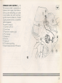
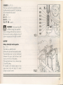
.SUPERSPORT
900 desmodue
Owne:r's manual
CR-SP
2
900 Supersport. Owner's Manual 1996@ by Ducati Motorcycles S.p.a.
=- edition, All rights reserved. Any reprinting or unauthorized use without the writlen permission of Ducati Motorcycles S.p.a. or Cagiva
America lnc. is expressly prohibited.
~-~-ed in Italy.
rn
-:od this owner manual corefully and poy special attention to statements preceded by the fallowing wards:
WARNING - Indicates a possibility of severe personal injury or loss af life if instructions are no fol
ed.
CAUTION - Indicates a possibility of personal injury or equipment damage if instructions are not fallowed.
NOTE: Gives helpful information.
CAa6VA
Trading SpA
Message must read: "If you belive that your vehicle has a defect which could cause a crash or could cause injury or death, you should
immediately inform the National Highway Traffic Safety Administration (NHTSA) in addition to notifying Cagiva North America. If
NHTSA receives sirnilor complaints, it may open an investigation, and if it finds that a safety defect exists in a group of vehicles, it may
order a recall and remedy campaign. However, NHTSA cannot become invalved in indivdual problems between you, your dealer,
or Cagiva North America. To contact NHTSA, you may either call the Auto Safety Hotline toll·free at 1·800-424-9393 (or 366-0123
in Washington D.C. area) or write to: NHTSA, U.S. Department of Transportation, Washington, D.C. 20590. You can also obtain
other information about motor vehicle safety from the Hotline".
3
m
IMPORTANT - READ BEFORERIDING
-
Welcome to the CAGIVA mo·orcycling Family! Your new Ducoti motorcycle is designed and manufactured to be the finest in the
field.
- Read this Owner's
n~c be10reriding so you will be thoroughly familiar with the proper operation of your motorcycle's controls,
its features, ccocoi ·';es::: a . 'rofions.
The purpose a! ""'£ - _"..c 's
·0 orovide instruction in all the thechniques and skills required to ride a motorcycle safety.
~ Your Docc" - c: -::: -::B 's en eXiremely high performance sport machine. Obtain proper instruction from on occredited motorcycle
insmxrio= o'2;:;-'=~cr oeiore riding your Ducati. Do not rely solely on the riding tips given in this manual.
This
'-::: "::.B 's ccoco e of eXiremely rapid acceleration and deceleration and very high speed. Improper use can lead to serious
occice=s. :X: -0· o'rcch a side car, trailer, or any other accessory to this motorcycle, Failure to heed this warning could result in
ass ~:
-x::''19 srablility and subsequent serious occident.
- -0 ensure 0 ong, trouble-free life for your motorcycle, give it the proper care and mointenance described in this owner's manual.
For more detailed information on your Ducati motorcycle, a Service Manual is availoble for purchase from any Cagiva/Ducati
dealer.
- When service is required, remember that your Cagiva/Ducati dealer knows what it takes to keep your Ducati in good condition.
- Due to improvements in design and performance during production, in some cases there may be minor changes between the actual
vehicle and the illustrations and text in this manual.
"0'
m
m
WARNING
-he maintenance and operation procedures outlined in this manual must be followed. Failure to perform the safety checks and
mointenonce operations listed can result in unsafe conditions which in turn can lead to serious accidents. Always wear a helmet and
prO:le' orotective gear when you ride. Obey all laws. Foilure to do so can seriously compromise your personal safety.
WARNING
This
surfaces,
4
=- c e is cesiqned ond intended for use on streetsand
5...c- .se coe a ead 0 upset or other accident.
other smooth, poved areas only. Do not use this motorcycle on unpaved
SAFETYWARNINGS
- _-ic Rulesvary fram jurisdiction to jurisdiction. Know the regulations in your jurisdiction before riding this matorcycle.
:;.:..50UNE IS HIGHLY FlAtvVV\ABLE
- . oys turn off the ignition when refueling.
=e extremely careful not to spill gasoline on the engine or exhaust system when refueling.
e er refuel while smoking or in the vicinity of an open flame.
- QU should swallow some gasoline, inhale a lot of gasoline vapor, or ollow some ga
~e to ge; in your eyes see your doctor
--nediately. If any gasoline spills on your skin or clothing, immediately wash i w' soap and water and change your clothes.
- Nays turn off the ignition and remove the key when you leave your motorcyc e u a-ended.
--e engine, exhaust pipes, and mufflers stay hot for a long time.
~ark the motorcycle where no one is likely to touch it.
)0 not park on a slope or soft ground, the motorcycle may fall over.
ever start or run the engine in a closed area. The exhaust fumes are paisonousand may cause loss of consciousness and death within
a short time. Always ensure adequate ventilation if you must run your motorcycle indoors.
eep your and your passanger's feet on the footrests whenever the motorcycle is in motion. Deep your hands on the handlebars at all
-·mes.
: you must transport your motorcycle in a truck or on a trailer, shut off the fuel petcock. This will prevent spillage from the carburetors
s ould the motorcycle lean over excessively.
NOISE EMISSION WARRANTY
Cagiva Commerciale S.r.l. warrants that this exhaust system, at the time of sale, meets all applicable U.S. EPAFederal noise standards.
This warranty extends to the first person who buys this exhaust system for purposes other than resale, and to all subsequent buyers.
Warranty cloims should be directed to Imanufacturer shall fill in his name, address and phone number).
5
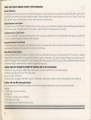
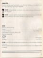
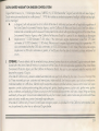
NOISE AND EXHAUST EMISSION CONTROL SYSTEM INFORMATION
Source of Emissions
The combustion process produces carbon monoxide and hydrocarbons. Control of hydrocarbons is very important because under certain conditions, they
react to farm photochemical smog when subjected to sunlight. Carbon monoxides does not react in the same way, but is toxic. Cagiva/Ducati
utilizes
lean carburetor settings and other systems to reduce carbon monoxide and hydrocarbons.
Exhaust Emission Control System
The Exhaust Emission Can 01 Sys'em is composed of lean carburetor settings, and no adjustments should be made except idle speed adjustments with
the throttle stop screw. Ire Exnous Emission Control System is seporate from the crankcase emission control system.
Crankcase Emission Control System
The engine is eculooed ".'~ c cosec crcnccose system to prevent discharging crankcase emissions into the atmasphere. Blow·by gas is returned ta the
combustion cha~oe'~'
~"+e c> cecoer a d the carburetor.
Evcporctive Emission Control System
California rJ1OiO(cyoeso'e ec 'ooeo w' 0 evooora'ive emission control system which consists of a charcoal canister and associated plumbing. This
system prevents -.,e escape 0; Cue vapors' om one carburetors and fuel tank.
Noise Emission Control System
Tampering with the Noise Control System is prohibited: Federal law prohibits the follOWing acts or the causing thereof: (11 The removal or rendering
inoperative by any person, other than for purposes of mainrenonce, repoir, or replocement, of any device or element of design incorporated into any new
vehicle for the purpose of noise control prior to its sole or delivery a the ultimate purchaser of while it is in use; or (21 The use of the vehicle after such device
or element of design has been removed or rendered inoperative by any person.
usrso
AMONG THOSE ACT PRESUMEDTO CONSllTUTE TAMPERING ARE THE ACTS
BELOW:
11 Removal of, or puncturing the muffler, baffles, header pipes or any other component wich conducts exhaust gases.
21 Removal or puncturing of any port of the intake system.
31 lock of proper maintenance.
41 Replacing any moving port of the vehicle, or ports of the exhaust or intake system, with parts ather than those specified by the manufacturer.
Problems with may affect motorcycle emissions
If you are aware of any of the following symptoms, have the vehicle inspected and repoired by your local Cagiva/Ducati
Symptoms:
11 Hard starting or stalling olter starting.
21 Rough idle.
31 Misfi·ng or backfiring during acceleration.
4) Aher-bum-ng (backfiring).
5) Poor pe.!()('Tl(loce (driveability) and poor economy.
6
dealer.
RIDING SAFETY
The points given below are applicable for every day motorcycle use and shoud be carefully observed for safe and effective vehicle
operation.
A motorcycle does not provide the impact protection of an automobile, so defensive riding in oddition to wearing protective apporel
is extremely important.
Do not let protective apparel give you a folse sense of security.
Before changing lanes, look over your shoulder to make sure the way is clear. Do not rely so e
a vehicle's distance and speed, or you may not see it at all.
When going up steep slopes, shift to 0 lower gear so that there is plenty of power
0
01'
e rea' iew mirror; you may misjudge
spare rather than over looding the engine.
When applying the brakes, use both the front ond rear brokes. Applying only one brake for sudden braking may cause the motorcycle
to skid and lose control.
When going down long slopes, control vehicle speed by closing the throttle. Use the front and rear brakes for auxiliary braking.
Riding at the proper rate of speed and avoiding unnecessarily fast occeleration are important not only for safety ond low fuel consumption
but also for long vehicle life and quieter operation.
When riding in wet conditions or an loose roodway surfoces, the ability to maneuver will be reduced. All of your actions should be
smooth under these conditions. Sudden acceleration, braking or turning may cause loss of control.
When the roadway is wet, rely more on the throttle to control vehicle speed and less on the front and rear brakes.
The throttle should also be used judiciously to avoid skidding the rear wheel from too rapid acceleration or deceleration.
On rough roods, exercise caution, slow down, and grip the fuel tank with the knees for better stability.
When quick acceleration is necessary as in passing, shift to a lower gear to obtain the necessary power.
7
Do not down shift at too high an r.p.m. to avoid damage to the engine from overreving.
Avoiding unnecessary weaving is important to the safety of both the rider and other motorists.
Do not exceed the legal speed limitor drive too fast for existing conditions. High speed increases the influence ofany condition affecting
stability and the loss of con rol.
Operate motorcycle on a' moderate speed and out of traffic until you have become throughly familiar with its operation and handling
charpcleristics under a concrions. This is a very high performance motorcycle, designed and intended for use by experienced careful
riders only!
A new moiorcvc.e -
•••
[lJ
":JE;
coexrec
occorong
to
0
special break-in procedure (see Running in recommendations) .
WARNING: Before siarting engine, chec for proper operation of brake, clutch, shlher, lhrottle controls, correct fuel and oil
supply.
Gasoline is extremely flammable and is explosive under certain conditions. Refuell in a well ventilated area with the engine stopped.
Do not smoke or allow open flames or sparks when refuelling or servicing the fuel system. Always close the fuel petcock when the engine
is not running to prevent flooding of the carburetor. Do not overfill fuel tank. Leave at least one inch oir space to allow for fuel expansion.
Motorcycle exhaust contains poisonous carbon monoxide gas.; Do not inhale exhaust gases and never runthe engine in a closer garage
or confined area.
Use only Coqivoz'Ducof
approved parts and accessories.
This motorcycle was not intended to be equipped with a sidecar or to be used to tow any trailer or other vehicle. Cogiva/Ducati does
not manufacture sidecars or trailers and cannot predict the effects of such accessories on handling or stabily, but can only warn that
the effecs "ill be adverse any damage to motorcycle components caused by the use of such accessories will not be remedied under
warrar' .
51 Uf
8
[]
!!rUM
•••
[lJ
WARNING: Do not ride the motorcycle with helmets a-c~-ec -c --:; -:x
e
+e -:; +e s co a couse on occident by distrocting
the operotor or interfering with normal vehicle operco-
PROTECTIVE APPAREL
Always wear a helmet. Most motorcycle accident fataliiies a"e c .e -c -:;c:: - -~For safety eye protection, gloves, and high top, sturdy boors s ~_ C C sc oe
The exhaust system becomes very hot during operotion, neve-:
- +s e -c_=· _ ·em. Wear clothing thot fullycovers your legs. Do
not wear loose clothing which could cotch on the contro e e-s ::x-~-s -ee s, or choin.
A passanger needs the same pro ection.
Any omount of alcohol will significantly interfere wi h your co'"
-:::s,:::-e- coero e your motorcycle. Don't drink ond ride.
LOADING AND ACCESSORIES
This motorcycle is designed to carry the operator and one ocsse-2ee er exceed the vehicle copacity bod os shown on the tire
informotion lobel.
The combined weight of the rider, passonger corgo ond oddr.occ accessories mustnot exceed 8821bs (400 Kgl. Cargo weightolone
should not exceed 44 Ibs (20 Kgl.
11 Load weight equally on both sides.
21 Keep cargo ond accessories weight low ond close 0 e ce-'e- o! the motorcycle.
31 Adjust rear suspension to suit load weight.
41 All cargo and accessaries must be secure for stable honoi g.
51 Do not attoch large heavy items to the hondlebars, front ~o <S 0" tender. Difficult handling moy result.
WARNING To prevent an accident, use extreme core when riding with accessories ond cargo.
Never ride
0
loaded motorcycle above 55 rn.p.h., a motarcycle's stobillrv and, performance con be reduced with the cargo.
9
xge
CONTENTS
Reporting of Safety Defects
.
Read before riding
.
.
Gasoline is highly fiammable
.
Noise emission warranty
.
Noise on exhaust emission control system
information
.
.
Riding safety
.
Loading and accessories
.
SPECIFICATION
Identification data - V.I.N. - Keys
Lobel location
Controls and instruments
Choke· Key switch ....
Electrical controls on the handlebar
Controls
TECHNICAL FEATURES
Engine.
.
.
Valve gear - Timing specifications
Fue ~eedsystem
.
lubr'ccio
Cooling
10
.
.
7
12
3
-5
.
16
17
.
.
18
19
..
.
20
2'
22
23
page
gn 'tion System
.
Hydraulic clutch control
.
3ra es .
.
.
ransmission
.
=rame - Seat - Wheels
.
-'res - Payload and tire pressure -'re 'nAation pressure - Tire wear, damage
v'in'mum tread dept.
Susoensions
.
:: ecmcol system
.
.
ecnicol system scheme legend
.
j: sebox - Battery
.
.
Borerv charging...
.
.
Overall dimensions - Weights .
Capacities - Tightening torque figures ....
tionol ports
.
c
o
,IDI G YOUR DUCATI
Breo -ln recommendations
Before starting the engine
Sorting the engine.............
.
iding the motorcycle
Bra ing - Stopping the motorcycle
25
26
28
29
-
30
31
35
36
37
38
39
40
41
.
42
44
.
.
45
46
47
.
.
24
page
Parking
.
Anti-Theft tips..
.
.
Additional considerations for high-speed
opemt~n
.
.
MAINTENANCE
Tool kit
Maintenance schedule
Periodic maintenance chart
Emission maintenance schedule
.
.
.
.
MAIN MAINTENANCE OPERATIONS
Engine oil and filter
.
Checking drive chain tension and chain
lubrication
.
Spark plugs - Air cleaner element
.
Carburetor idle speed adjustment
.
Front and rear brake - Clutch
.
To replace the bulbs
.
Headlight alignment.
Motorcycle care
.
Storage.
..
.
48
49
50
51
52
53
55
56
57
58
59
61
62
66
67
67
page
Consummer information
CAGIVA LIMITEDWARRANTY ON
EMISSION CONTROL SySTEM
MEMORANDUM ON ROUTINE
MAINTENA CE
.
68
.
69·
.
71
QUICK REFERECE INDEX
To renew a blown fuse .
Checking electrolyte level
............
Tightening torque figures
Checking engine oil level and changing
the oil ... .....................................
To adjust and lubricate the chain ..........
Checking the spark plugs ..... . . . . . . . . . . . .. .
Renewing the air cleaner element .......
Checking brake pads and brakes ond
clutch fluid level ...........
...............
Renewing the bulbs
Headlamp alignment
37
37
40
56
57
58
58
61
62
66
11
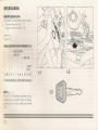
SPECIFICATION
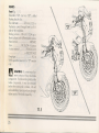
IDENTIFICATION
DATA
Your DUCATI is identified by two numbers:
• - frame number (see fig. 1. l)
- engine number (see fig. 1.2).
Frome No.
Engine No.
VEHICLE IDENTIFICA T10N NUMBER (V.I.N.)
,--
00. ESl6
Eli61 E TYPE
I
I
Z OM lC 0 F F H
no
rr----....
MODEl YfAR
r
*A
r='
B 01 2345
~U
1.2
1.1
* Varies-canbetluu9 orX (Check digitforfactoryuse)
KEYS (fig. 13)
Your DUCATI has been delivered with on
universal key (in double copy) for starting,
steering ex:k and for saddle and helmet
lex: .
12
1.3
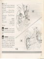
LABEL LOCATION
10
12
CAUTION
Never flit tank so teetrevet
rises into
filler neck. If tank is cverttned.tbeat
may cause fuel to expand and lIow
into Evaporative
Emission Cootro!
System resulting in hard starting and
engine hesitation.
W~1iG
YOUA OuO,Tl ••.•
OT~YClE
PEO WlTl-i A W~iNG
UGH1" FlASHING
SlOE STANO IS
coweaee
5
IS EO\.!IP·
WHEN
n.e
.ONe
...awE\IEA.
IT IS THE RIOER"S REsPONSlBlLIl''I'
tNSUAE ThAT
SIC€: ST.o.NO IS STO'o'r'EO
ne
TO
cc-.
~mL
Y &FORE
STARTlNG
OUT
FAILuRE
iO
06SER'vE
1l1IS YllAA:.lh(I COUlO
RESUl T IN AN
uPSET AH() CONSEOUENT SERtOuS BOOIly
~9
c-~_~
__'
O~~Ci~
111 M.,:t~~
o\\.q,t
t.LOM.lt
TkA.~ l~"
A.~PlAR.
~.
i'\b"\ ~cre
ma
I
9:XX)RPM
CtillllI;:
""""'."""'"
9208RPM
2
W,",/'ININO
OOHOTAffiMC'T!OlOOl(MOi.OITli!SfItJAI~7HI)IS/;Ol
A'NNDSltEl.D.BVTA"'AERODYtIA.'.ocFAIIJ~CH.Y.FAll.flt
~1,~~~~~T~i.Olll~,~
12
13
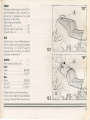
MarlJIactured by QGNA TRADINGS.p.A.
DATE.
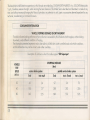
GVWR 7KO lb,/351 Kg
GAWR fronl. 286.6lbs-130
Kg wilh 120170 2R 17 lire, MT 3.50x17 RN 01 32.7 PSI cold.
GAWR reor. 487.4lbs-221
Kg wilh 170/60 ZR 17 lire, MT 5.50x17 RIM 01 36.9 PSI cold.
Tlis veh!cle coofcrms to cu CWXa.ble Federal Motor Veichle Sa.fety sto.t'O:lrds
it effect on the dote of rmruturte-e st'own above.
VEHICLE EMISSION CONTROlINFORMA TION
ITEM
Veticte LO. No. : &*$&WW§@$§X'}@@§@§R§0.§§OO
\
'tion f
2.lcIespe:eo!RPH::
Type c\o"if~alim
2
, Molorcycle
1 kle rrixture
~o..1)t:rI
Q.:sn;:J.02
SPARK PU.Xi: OiAt".PD:.2A6l-1(
R£L SP£CKAID.'S
Gasolile 1J"Cde: ~Res ecrch ();h!;ae: 9t
~
=r~
T
-m
&-gre
-[:'It:;
cL:
Sf
SA::
20 'vi SO
~tc::i.r-~
'"'Is~CD""':rcIstQllS.fPA
~s!,~systeotE.M.
~~~:~~
OQE ntE:-lP
\
"'ion r
2. k1.e speed {RPt1:
3. k1.e mixhre
4. Valve ctecrerce
(in 2. ex!
SPARKPlIJi: QiAWQaAUl(
FUl SP[(HA ~S
GasI1irle !TOile: re!1iW' a.eadetll
zesecxn Octane, <;1 mil.
MOTORCYCLE NOISE EMISSION CONTROL INFORMATION
THIS ~
MOOEL YEAR MOTORCYCLE.~
MEETS EPA NOISE EMiSSm REQUIREMENTS OF 80 dBA AT 3850 RPM
BY THE FEOERAL TEST PROCEDURE.MODIFK:ATIONS WHICH CAUSE THIS
MOTORCYCLE TO EXCEEO FEDERAL NOISE STANDARDS ARE PROHIBITED
BY FEDERAL LAW. SEE OWNER'S MANUAL.
SPARK"'1.JJj GAP L'tCIl: 0.6-0.7
no.E
1..l.SRI:A.'lT SilEIHATD/S
VEHICLEEMlSSONCONTROLLABEL
I
E.NCIl(FAJ,llT:PCG.'XIPOGtR •••
ras VOIClE CDIf'OIIIJSTOU.S. EP,l ANDc.tJ.J'DRtU REQ.lA TJ)HS
.lJlP\JCABlET0I'l94UOOElTEUt.(lItotOTORCTCLES.
OCtl£O'SP\.A((t.lENT:'J04cc
SPECHAID.'S 00 ADJ.IS1l£l(TS
S?£CHAIDlS
~
O' bTDC at i:!I.e speed
tb
taerr.s
uoo!. 50
Ib
tceres
No
trnen:s
~1!n:ngO.1Orul
ClQ5~ 0.02 mn
SPARKPU.J3GAP\IrmI: 0.&-0.7
ENIJK It..6RO.'lT SPECFO.TD6
~~p
I
I
[JAP~~:~~~~(w)[Ni02
~_IOlIoM.M.r:
CAcrv""RAIlOICS.p1.
Y"1OA..c..~tl.l
cOllZ8Cl.otNa
I
ITAll
MAIO\TA RITORI-l) CAENAGGIO
DELIVERY BACKFLOW DREINAGE
Ergn!! lit: SAE 20 'W 50
Type: SF
--",,:'0'(
(.IoJIS1'{t-
r;TtlIQ:2O(I"~~D
-Tlll'!l!iOtI?ll'aO
6
~~~C~A~G~IV~A~T~R~AD§IN~G~S~~~.~A.:-~8~0~LfOG=N=A=-=I=TA=L~Y======~~_4
~~~~~
~::w6~/#72
U.~~1I
•
14
7
only for California version
~~~~
WARNING
CIIHTAIHS
tllGNl Y COMPRESS[O
GIS.uSfOIClY
PERFECTLY
Dill
N1TROGEN
G'S. OTHER GASES MAY
ClUSE
fXPLOSIDN.OOHOI
INCIH£RHf. R(fER 10
OWNER'S
MANUAL
rOR
L-R_[G_U_I_"l_IH_G __ GI_S_.
WARNING, DO NOT ATTEMPT TO LIFT THE MOTORCYCLE
BY THESE HANDLES. THEY ARE PROVIDED ONLY AS A
HANDHOLD FOR THE PASSENGER. FAILURE TO OBSERVE
THIS WARNING COULD RESULT IN AN UPSET AND CONSEQUENT SERIOUS BODILY INJURY.
~-
9
8
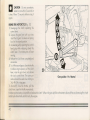
CONTROLS AND INSTRUMENTS
a
Instrumentcluster (fig. 2.1):
1) Speedometer (mph)
a) Trip counter
b) Odometer
c) Odometer zerosetting knob
d) Start limit of engine speed
D
2
3
4
8
CAUTION - This zone indicates
the maximum limits of engine
speed and running the engine in the red
zone will adversely affect its service life.
2) Tachometer.
3) Green wll = Gear selector is in neutral
position.
4) Yellow wll = Fuel reserve.
5) Blue wll = Headlamp high beam ON.
6) Green wll = Outer lighting ON.
7) Red wll = Insufficient oil pressure.
7
c
2.1
d
6
5
10
3
4
D
CAUTION - Running the engine
with insufficient oil pressure will
cause serious engine damage.
8) Green wll = Turn indicators.
9) Red wll = Battery charge warning
(light always on).
10) Redw II = Side stand emergency lights.
1 1) Oil temperature indicator (only for "SP"
version).
9
8
7
2.1
C
a
d
6
5
10
15
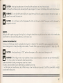
CHOKE (fig. 3.11
It is located on the left half-handlebar. Turn
it in a counterclockwise direction to activate
this device (BI.
"
When the motar is sufficiently
~
warm, return the choke control
device to the res posrion by turning it
clockwise.
"
~
Do '10'
s nor.
J5e
+e cno e -r 'he mo ar
KEY SWITCH {~ig. 3.2
It is located on he fork head and can
De
set on four positions:
cA. Run.
cB· Stop.
cC. Steering lock.
cD. Parking lights and steering lock.
3.1
B
IMPORTANT - When in position «B»,.C·
and -D- the key can be withdrawn.
"
CAUTION· Never leave the key
~
in «ON» position when engine is
off, in order to avoid damages to coils.
•••
W
WARNING - Never turn the key to
cLOCK·
is moving.
16
when
the motorcycle
3.2
ELECTRICALCONTROLS ON THE HANDLEBAR
Le~ (fig. 4.1)
Switch B, (LIGHTS), lights change aver,
two positions:
«LO. = Law beam
cHI· = High beam
Switch C, (TURN) three positions turn indicator:
Centre = OFF
.L. = Left turn
cR. = Right turn
Button D, (HORN) warning horn.
4.1
:====================
F
Right (fig. 42)
Switch F, three positions:
cOFF. (Ieft+right) stop
-RUN. (center) running
Button G, .START. starting.
4.2
L-L.
--'---
17
CONTROLS (fig. 51
A keyoperoted switch (11 is locoted at the
center olong with on onchoring lever (101
for the fuel tonk ond the fuelcop (81with key
•••
[lJ
WARNING - Gasoline is extremly
Aommoble and can be explosive
under certoin candi ions. Turn the ignition
switch off when refue· g.
- Do not smo e or a ov, crnes or sparks
in the oreaw ere' e"lO'orcyce'srefueled
or gasoline is sroreo.
- Do no; 0 et'
e 'an { ere s ooio be
no fuel in he filler nec J. Alier re el'ing
moke sure the tonk cop is closed securely,
On the right-hand side of the handlebar
a twisting grip (51 controlling the accelerator is placed beside the electrical controls.
In front of the knob the front broke pump
with tonk ond lever (31 is placed.
On the left-hand side of the handlebar a
pump is ploced with tank ond lever (61of
clutch control. Beside the electrical controls
there is the choke (71control lever.
On the right-hand side of the motorcycle
the pump and foot pedal (41of reor broke
ore placed,
The service rod (131 is located under the
fuel ton,
18
On the left-hand side of the motorcycle,
next to the footrest, the gear shift lever (21
and the loterol stond (91ore located.
•••
[lJ
WARNING- Failure to insure thot
stond is stowed completely could
result in an accident ond consequent serious bodily injury.
In addition, in the rear side it is possible to
reach the comportment under the soddle
by means of a lock (1 11. In this compartment there are also the two pins (1 21 to
secure the helmet lock otthe frome.
TECHNICAL FEATURES
ENGINE
Twin cylinder, 90° V twin, 4-stroke, mounted in a steel tubular double cradle shaped frame.
Bore, mm./in .
Stroke, mm./in.
Total displacement cm3 /in3
Compression ratio
Mox.cronkshoft power kW (HPI...............
..
at rpm .
Max engine speed rpm .
..
..
.
..
... 92/3.62
68/2.67
904/5514
1:9.2±0.5
59 (801
...7.250
9.000
WARNING - Under no circumstances must the max. engine speed must be exceeded 9.000 rpm. Thin can cause drastic
damage to the engine, which can in turn couse rear wheel locking and uspest!
19
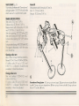
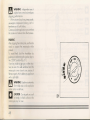
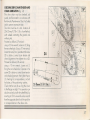
VALVE GEAR (fig 61
Valve
our motorcycle featuresthe "Desrnodrornic"
valve gear system.DUCATI is the only make
which uses such a sophisticated system.
Measurementswith a free play of: 0 mm/in.
Inlet: 11.76 mm/0.46 in.
Exhaust: 10.56 mm/0.41 in.
lift
TIMING SPECIFICATIONS
Inlet valve: 043 mm/1.69 in.
Exhaust valve: 0 38 mm/1.49 in.
Measurements with 0 tree olay of: 0,20
mm/0.0078
in.. , 1'1 '0.04 In.]
Inlet valve opening: L3° 200 De are TDC
Inlet valve closing: 8Y
a~e' BDC
Exhaust a e openi g: 82° 58° oerore
BDC
Exhaustvalve closing: 46° (20°) aLe' -roc
The tappet clearances, with the motor
cold, should be:
en
Opening
rocker arm
Inlet:0.10+0 12 mm/0.0039+0.0047
in.
Exhaust0.12+0. 15 mm/0.0047 +0.0059 in.
A working play (AI up to 0.05 mm/
0.0019 in. is allowed. Should this be
exceeded, it should be adjusted.
Closing rocker arm
Inlet and exhaust: 0.00+0.02
mm/
0.00+0.00078
in.
A working play (BI up to 0.20 mm/
0.0078 in. is allowed. Should this be
exceeded, it should be adjusted
20
6
Desmodromic Timing System· 1. Opening rocker orm (upper]. 2.Upper rocker arm odjuster. 3.Hole
rings. 4. Closing rocker orm odjustertlower]. S. Return spring of lower rocker. 6. Closing rocker arm
[lower]. 7. Camshaft. 8. Valve.
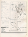
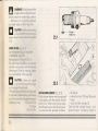
FUEL FEED SYSTEM (fig. 7.11
By means of electrical pump and filter.
Dryair inlet and cleaner, located under the
fuel tank.
The fuel feed system consist of:
11 Fuel filler cap;
21 Fuel level indicoting device;
31 Fuel hand cock for stopping the fuel
feed;
41 Fuel filter;
51 Electric pump;
61 Pump filter
71 Breather valve;
01 Feeding;
b] Return;
c] Cap breather pipe.
Provided with two carburetors: .. MIKUNI
Type
Carbo Main specifications
-
BDST 38 B 73
7
6
2
7.1~=======================_===============~
,~==========-
Choke mm/in
38/1.49
Main nozzle
140
Idling nozzle
37,5
Needle valve nozzle
Y-2
Starter nozzle
.70
Needle nozzle5C22 (1 pos. from top]
Evap. emission system consistsof (fig. 7.21:
11Canister;
21 Non return valve;
31 Fuel tank;
41 Induction monifold.
a -TO
HOT AIR INLET
HORIZONTAL
MANIFOLD
JET
7.2L-
a -
TO VERTICAL IrIANIFOLD
~
21
LUBRICATION (fig. 8)
Forced-feed gecr pump, oil filtering through
strainer; oil filter cartridge and low oil
pressure warning light on instrument cluster, lubricant cooling radiator.
1) Pipe union for oil sump breather gases
with recovery chamber.
2) Oil inlet plug.
3) Level indica Of.
4) Oil drain plug_
S) Net file'.
6) Oil fil'er cc+' ge.
7) Pre550sa .
8) Cooling radiator.
9) Oil temperature transmi ,er or ~ar'SP"
version).
It is possible to order at CAG . .:. JUCATI
"Spore parts Services' t e "Cc-ooretor
float chamber
hea··"g
cod.
699.2.037.
2
1A).
8
8
22
COOLING SYSTEM
Air cooling by natural heat dispersion through the large fin on both cylinders/heads
sent into them by external pipings. Engine oil cooling through radiator.
The cylinders are further caoled by the motor oil
WARNING - Avoid engine high speeds, when motorcycle is standing, to prevent undued engine overheating, because of no
air flow being present.
WARNING - Do not obstruct or deflect airflow through the radiator by installing unauthorized accessories in front of the radiator.
Interference with the radiator airflow can lead to overheating and consequent engine damage.
IGNITION
Electronic Iype with inductive discharge.
Trade-mark ..
Two-step automatic advance:
gradually increased up to 360 (1700 to 2600 rpm
(Check using a stroboscopic light)
.
KOKUSAN
...... 60 (up to 1700 rpm ± 200)
.
±
300)
Spark plugs
Trade-mark
Electrode gap.
.........................
.
CHAMPION RA6HC
..0.6 mm/0023
in.
CAUTION: In case of difficult ignition, deoxidote by meons of an odequate product, the contocts on the gearbox and the terminals
on the connector.
Periodically check that the carburetor vocuum signal pipe is correctly connected to the carburetor as well as to the gearbox, and that
it is not buckling.
v w
oN
AN
23
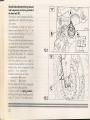
IGNITION SYSTEM (fig. 91
11 Ignition key switch located on the fork head.
21 Electronic ignition control units located on the filter box, under the tank.
31 HT coils located on the filter box, under the tank.
41 Electronic ignition pick-ups in oil sump leh side cover.
51 Vertical cylinder spark plug.
61 Horizontal cylinaer soork plug.
9
24
HYDRAULIC CLUTCH CONTROL Ifig. 101
The motorcycle clutch is operated by an
hydraulic control system, which ollows 0
more accurote and less tiring use. In order
to avoid sudden kicks, which could damage the transmission elements, a flexible
coupling has been inserted, so to soften the
clutch engagement.
The system consists of:
11 Clutch ~ump IPS131
21 Control lever
31 Pump-clutch conneciing pipe
41 Thrust plunger
51 Release rod
61 Pushdisc
71 Clutch bell
81 Oil breather pipe fitting
91 Separate reservoir lonlv for "SP'version].
10
25
BRAKES
Front (fig
1 1. 1)
Bimetallic ("CR') cast iran ("SP"I. drilled
flooting double disc.
Disc diameter
320 mm/12.6 in.
Hydraulic control hrough lever on R.H.
side of the handlebar.
Broking surface ... 88 CfTl2 • 13.64 sq.in.
Brake calipers w' d'!!eref'+ia'ed oistons.
Manufacturer
3 EMBO
Type
P4.30/3L. L pistons
Friction material
FREN{)() 222
.... or FERODO 450
Pump type
PS 16
With seporate reservoir for 'SP' version
only.
•••
W
WARNING· Do not let any oil co-
me in contact with any disc bra e
components. If oil should be spilled on the
brake components, it must be removed
before the mo orcycle is ridden. Oil Nill
reduce bro ing capocityand con damage
rubber ports of the bra e assembly.
26
Rear (fig. 112)
Fixed, drilled disc type. Anti-bouncing
device for rear wheel bracking (only for
'SP' version).
Disc diameter
245 mm/9.64 in.
Hydraulic control through pedal on R.H.
side.
Braking surface ..... 25 cm2/3.87 sq.in.
Brake calipers:
Manufacturer
BREMBO
Type.
. .. P2.105N
Friction material
.... FREN-DO 222
.....................
or FERODO 450
Pump type .
.
PS 1 1
•••
WARNING - To avoid a serious
~
burn, never touch a hot exhaust
pipe during inspectiong or replacing brake
pads .
•••
WARNING-Do not let any oil co~
me in contact with any disc brake
components. If oil should be spilled on the
brake components, it must be removed
before the motorcycle is ridden. Oil will
reduce braking capacity and can damage
rubber ports of the brake assembly.
27
TRANSMISSION
Clutch dry type, controlled through lever on the L.H. side of the hondlebor.
Engine-gearbox mainshaft transmission with straight toothed gears.
Ratio.
6-speed, constant-mesh geors, control foot pedal on L.H. side.
Total gear ratios
1st..
.
.
2nd
................................•..
3rd.
.
__
.
4th
.
5th
.
6th
.
Transmission between gearbox ana rear wheel, by chain:
Make.
Type..
..................•.....
Size
Final drive ratio (pinion/crownl.
.
31/62=1/0.5
.. 37/15=12.169
.30/17=8706
..27/20=6660
.24/22=5382
. 23/24=4727
.
24/28=4228
.
.
.
D.l.D.
520 VL4
links98,5/B"x1/4"
.
15/37
•••
WARNING - The above gear ra ios ore the homologated ones and under no circumstance they must be modified. However,
with a view to assistcustomerswishing to make their motorcycle suitable for closed course competitive racing, the Cagiva North
America. Inc. is always at their disooso 'or any information about ratios different from the standord ones, which may be requested
through the au horised DUCAn Dee ers.
t.1J
•••
t.1J
WARNING· For e reDiacemen of the reor crown wheel, contact the Authorized Dealer Assistance Service: the incorrect
replacement of thiscomponen could seriouslyendanger the safety of the rider, and cause irreporable damage to the motorcycle.
Such modified motorcycles are not covered by Cagiva/DUCATI Warranty and cannot be used on normal roads, since they are
not in compliance with Dept. of Transportation standards.
28
FRAME
The frame is trestle shaped, mode of Chromium-Molybdenum tubes, very sturdy in its
structure as a consequence of our great
know-how on the matter.
Tube inclination [motorbike
without pilot] .
.
25°
Steering angle Ifor each side]
2SO
Forward stroke, mm
103
"CR"
A
SEAT
Dual-seattype. To remove the seat presson
the rear end and, at the same time,release
the lock IA. fig 12.1). The "SP"version is
equipped with a cover B, fig. 12.2) for the
single-seat transformation.
WHEELS
Three spokes light-alloy rims.
Front
Make
Size...
BREMBO
3 .50x 17'
.
Rear
Make
Size ISP)
Size ICR).
.
...... BREMBO
...... 5.50x17"
.
4.50x17"
Wheels have hubs with removable pin.
The rear wheel is fitted with a special flexible
coupling. To remove it firsttokeout the chain.
29
TIRES
TYRE INFLATION PRESSURE
Front
Front ...
"tubeless" radial type.
Make (SPI.
.
MICHELIN A89X
Size (SPI.
. 120/70 - ZR17"
Make (CRI
DU LOP SPORTMAX
Size (CRI .
.
120/60 - VR17'
Rear.
Rear
"tubeless" radio type.
Make (SPI
_..
Size (SPI..................
Make (C I
DG
Size (CRI
' C::
89X
'70; 60 - Zl?l 7"
LOP SPO .'I/'IX
160/60 - J 7"
T
WARNING-Forkailleakagecan
cause loss of stability and so e
handling. Have any problem correcreo
before riding the motorcycle.
.
.
MINIMUM TREAD DEPT
2,1 bar; 2,14 kg/cm2
2,3 bar; 2,34 kg/cm2
NOTE - Measure the tire pressure when the
tires are cold (that is, when the motorcycle
has not been ridden more than a mile
during the past 3 hours].
- Tire pressure is affected by changes in
ambient temperature and altitude, and so
the tire pressure should be checked and
adjusted when your riding involves wide
variations in temperature or altitude .
PAYLOAD AND TIRE PRESSURE
Faillure to maintain proper inflation pressures or observe payload limits for your
tires may adversely affec handling ana
performance of rour motorcycle and carresult in loss 0 conlrol. The maximum
recommended load in oddion a vehicle
weight is 156 Kg (344lbsl including rider,
passenger and baggage.
- Check the tire pressure every time you
ride, using an accurate gauge.
2 mm (0.08 in.]
Rear
2 mm (0.08 in.]
- Visually inspect the tire for cracks and
cuts, replacing the tire in case of bad
damage. Swelling or high spats indicate
internal damage, requiring tire replacement.
- Remove any imbedded stones or other
foreign particles from the tread.
•••
[lJ
WARNING - Do not ride on a tire
with less than the minimum tread
depth or with any other defect.
•••
[lJ
Front
nREWEAR,D~GE
As the tire tread wears down, the lire
becomes more susceptible to puncture and
failure. An accepted estimate is that 90%
of all tire failures occur during the last 10%
of tread life 190% worn]. So it is false
economy and unsafe to use the tires until
they ore bald.
- In accordance with the Periodic Maintenance Chart, measure the dept of the
tread with a depth gauge, and replace
any tire that has worn down to the minimum
allowable tread depth.
••
CAUTION - Have the wheel bel•••
once inspected whenever a new
tire is installed.
•••
[lJ
WARNING - To ensure safe han-
dling and stability, use only the
recommended standard tire for replacement, inflated to the standard pressure.
Under no circumstances use a tube type
tyre. Failure to heed this warning will very
probably lead to sudden tire deflation and
subsequent serious accident.
30
~-------
~----
--
--'
NOTE: Tire pressure should be checked when the tires ore -cold-, before you ride.
WARNING - Maximum inflation pressure must not exceed specification located on tire side wall.
If a tire tread shows crosswise lines, it means that the tire is worn to its limit. Replace the tire immediately.
SUSPENSIONS
Front
Oleodynamic upside-down fork.
With outer system for rebound and compression adjustment and spring preload for 'SP' version.
SUSPENSIONS
Make
Type.
.
Borrel diameter
Travel on the legs axle
Oil quantity for each leg
Oil level to the borrel
Oil type
CR
_..........
.
SP
MARZOCCHI
.
SHOWA
.. 40 USD/E
.
SPECIALGD021
40 mm/1 .57 in.
.
41 mm/1 .61 in.
120 mm/4.72 in.
120 mm/4.72 in.
380 cc/23.18
cu. in.
.
440 cc/26.58
cu.in.
.
90 mm/354
in.
108 mm/4.25 in.
MARZOCCHI Art. 550009 or SAE 7,5 SHOWA S.S8 or AU. or SAE 1OW20'
31
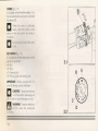
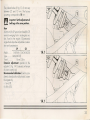
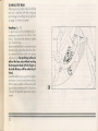
Idraulic brake adjustment during rebound
and compression and spring preload of
the front fork (SP).
The hydraulic braking degree of the fork is
adjustable both in rebound and compression actions.
The adjustment is made by means of
external screwadjus'ers (A in fig. 13.1 for
hydraulic rebound bro. ing, C in Fig. 13.2
for compression bra 'ng.
Whenyouroa:e
eo [usrmerrscrewvou
can hear various clic ,each one of em
corresponds to a bra ing position.
If you fully screw in the screw to loe 'you'll reach the position "0", corresponoing to the max. braking effect.
From this position you can rotate in
counterclockwise direction and count the
various clicks, which corresponds to the
positions 1, 2 etc. respectively.
Standard positions are as follows:
- compression: 6th position
- rebound:
411 oasi ion
The max. value is of 14 clicks. corresoonding to the min. bra ing posi ion,
In order to modify the spring preload of
each leg, tum the upper adjusting screw (B,
of fig. 13.1) wi h 022 mm allen wrench.
13.1
13.2
.=
32
iWI
The preload value (1 fig. 13.1) can very
between 25 and 10 mm. The factory
presetting corresponds to 18 mm.
•••
t...:.J
lmportont- set the adjustments of
both legs ot the same positions.
Rear
Aluminium (for SPversion) and steel (for CR
version) swinging fork in rectangular see
tion, fixed to the engine. Oilpneurnofic
single-shock absorber adjustable in extension and compression.
SP
CR
Make .
SHOW A SACHS BOGE
Type
GD022{)()lOX
Travel
65 mm/2.56 in.
Extensive adjustment: operate on the
adjuster (1, fig. 14.1) situated on the eye
of piston control rod.
Recommended calibration: from the completely closed position [clockwise], loosen
the register by:
-1 turn (SP);
6 clicks (CR).
14.1
»:
(. (
14.1
33
Compressive adjustment: operate on the
adjuster (2, fig. 14.2) situated at the
bottom of shock-absorber tonk.
Recommended calibration: from the completely closed position (clockwise), loosen
the register by:
-1 turn (SP);
25 clicks (CR).
Spring preload: 0 modi'
;he spring
preload it is necessary ooero:e op e ring
nut (3, fig. 14.2.
Recommended value:
(SP) 10 mm of pre lood.
(CR) 14 mm of pre-lood
34
C
CAUTION - The factory suspension selling is for rider only. If a passenger is to be carried the suspension must be adjusted.
Pressuresellings far rear shock absorbers: 10 bars/ 145 p.s.i. (SPI. 12+ 15 bars/174+217
m
p.s.i. (CRI.
WARNING - Only dry nitrogen may be used. Entrustthis operation to your Cagiva/Ducati
dealer.
•••
WARNING - Never disassemble the shock absorber. It contains highly compressed gas. Contact your au horized Cagiva/
~
Ducati dealer for such major service. Do not incinerate. Returnto Cagiva/Ducoti Dealer for proper disposol.
Do not drill the shock! Incineration or drilling could lead to explosion I
•••
WARNING - Modifications of the motorcycle, or removal of equipment may render the vehicle unsafe or illegal.
~
Obey
011
federal, state and local equipment regulations.
ELECTRICAL
SYSTEM
Independent circuits. Main components:
Headlamp - in rectangular shape, iodine, double filament, 12V-55/60W - H4 bulb.
Instrument cluster, 12V-l ,2W signal bulbs, 12V-3W instrument illumination bulbs.
Electrical controls on hondlebcr.
Direction indicator, 12V-l OW bulbs.
Horn.
Stop light switches,
Battery, 12V-16 Ah.
Alternator 12V-350W.
Electronic voltage regulator protected by a 30A fuse, located on the right side of the bonery support.
Starter motor 12V-o,7 kW.
Tail lamp unit, 12V-21 W bulb for stop light, 12V-5W bulb for number plate light
35
-
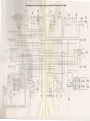
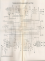
ELECTRICAL SYSTEM SCHEME LEGEND (see page 72)
1 Headlight
2 Front, right turn indicator
3 Front, left turn indicator
4
5
6
7
8
9
10
11
12
13
14
15
16
17
18
19
20
21
22
23
24
25
26
36
Horn
Revolution counter
Speedometer (m.p.h.)
Instrumentcluster warning lights
Regulator
Key switch
R.H. grip switch
L.H. grip switch
Front, stop light switch
Rear, stop light switch
Neutral worn. light switch
Oil pressure sender
Side stand switch
Fuel level gouge
Fuel pump
Relay
Turn Aashi'19
Alternoror
Ignition pic up
Ignition module
Taillight
Fuse holder 30A
Coil (horizontal cylinder)
27
28
29
30
31
32
33
34
35
36
37
Coil (vertical cylinder)
Spark plug (horizontal cylinder)
Spark plug (vertical cylinder)
Fuse box
Starter motor
Remote starting switch
Battery
Rear, right turn indicator
Rear, left turn indicator
Oil temperature indicator (only SP)
Oil temperature transmitter (only SP)
Wire color code
R
Red
G
Green
Y
Yellow
V
Violet
P
Pink
Lb
light blue
GR
Grey
BN
Brown
8K
Black
W-R
White-Red
G-W
Green-White
GR-R
Grey-Red
R-BK
Red-Block
O-W
Orange-White
Y-G
YellowGreen
Y -BK
Yellow-Block
GR-BK
Grey-Block
R-G
Red-Green
O-BK
Orange-Block
V-BK
Violet-Block
W-8
White-Blue
R-B
Red-Blue
G-BK
Green-Block
G-B
Green-Blue
Black color are alilarth cables
Th
oil temperature indicator (36) and the oil temperature transmitter (37) are only for "SP" model.
@
~--
-~
BN£C
h
®
@
~-~rCGW}-
(+-~-~~A-+rl
y
YB16AL -A2
18
@
0/8k
l ~~"'.
R
@
~
'-./
R
L-BN
RIB
~/B~@)
R/BK
O/BK
8
}r
+J::I::::::!=:+1==l:=+-U-------+-t----:=
~'~/BK
W/eN
'-'
LB
'-./
RIB
'-./
W/R
'-./
Y/BK
-e-
Y
--+----+-+++--+--H----l-++++---I----+--l-
LW/G
Y
0)
GR/R
••••/BK
r++-+++++-++----H-li---+++-H----+--++--
~W/B'
.:
GR
~
r
~~--<".'.K
n"' 0J
rr 8" ...
,,, \/
.11
Y/.
WIO
GR
V/BK
BN
Y
~
Y/O
U
v
U!
U!
'-------+---
L..-
Y
-----'
O/Bk ----
'-
RISK
I
ff!.
~1
U!
®
I~=========.------'
BN
B
R
~~GR
"/~@
.
l
IR
~W/BK
[--
W/6K
w
Y/G
~r!
~@
GR/R
-
~I
Ir~@j
E.
@
;
@
~'
I
~~@
~
v
@
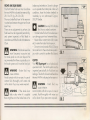
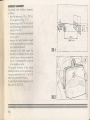
FUSEBOX (fig. 15 1)
The fuses used can be reached by remaving the protection cover (A). Only five fuses
are connected to the circuit:
A1
B2
Al = 30 A
B2- C3 = 15 A
04- E5 = 7,5 A
(F6 - G7 - H8 = spare)
C3
~
W ARNING- Never usea fusewith
F6
a different rating than specified.
Serious damage to the elctrical systemor a
fire may result;causing a dangerous lossof
lights ar engine power at night ar in traffic.
G7
H8
t.lJ
D4-----!--\t~1
E5
15.1
BATTERY
BaHery electrolyte level inspection
(fig. 152)
The bcttery is under the tank.
lift the tank and check the electrolyte level.
The electrolyte level must be maintained
between the upper and the lower level
marks on the front of the botterv.
If the electrolyte level is low, remove caps
11) and fill botterv.
Fill carefully with distilled water to the
upper level mark with help of a small
syringe or plastic funnel.
15.2
37
-••
CAUTION - add only distilled water to the battery. Ordinary tap water may shorten the life of the battery .
•••
- When adding distilled water, make sure the breather tube (2, fig. 15.2) is connected to the battery breather out let.
The battery breather tube must be routed so it is not bent or twisted. A bent or or kinked breather tube may pressurize the battery and
damages its case .
•••
WARNING - The ba ery contains sulfuric acid. Avoid contact with skin, eyes or clothing.
~
Antidote: OCER
- Flushwith water. INTERNAL - Drink large quantities of water or milk. Follow with milk of manesia, beaten
egg or vegetable ol _Co ohysician immediately. Eyes: Flushwith water for no less than 15 minutes and get prompt medical attention.
- DEEPOUT OF EAC- 0" C- cOREN_
- Batteries proouce ex
-ve gases_ Keep sparks flames and cigarettes away.
- Always pro-ec; eyes ,,~
,', -ng near batteries.
lottery charging
Remove the battery from the rno;orC'.~ iO ovoid electrolyte spill and the corrosion of frame or other parts of the motorcycle.
Check the electrolyte level in eac ce _ f he electrolyte level is low in any cell, fill to cover the lower level line but not to the upper level
line since the level rises during c -g-"9Remove the cops from all cells, a
coonect the battery charger leads to the battery terminals Ired to +, black to -I. Charge the battery
at a rate of 1.5 amps.
••
CAUTION - Do not use c -- n rate battery charger, as employed at automotive service stations, unless the charging rate can
•••
be reduced fa -he e:e 'ec.J-red for motorcycle batteries.
- Charging the OO-e", c: c -c-e n- ner than specified may ruin the battery.
After charging coecc -ne eIeG
e evel in each cell. If the level has fallen, add distilled water to bring it back up to the upper level
line. Insall the caps on e cess instoll the battery .
•••
WARNING - Batteries produce explosive gases, ventilate when charging or using in enclosed spoce.
~
- When using a battery charger, connect the battery to the charger before turning an the charger.
This procedure prevents sparks at the battery terminals which could ignite any battery gases.
38
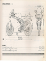
OVERALL DIMENSIONS mm (in)
730(28.74)
16
1410(55.51)
2030 (79.92)
WEIGHTS
Kerb weight (fuel tank empty)
Kerb weight (driver 70 Kg/ 154 Ib + full tank)
With driver and passenger (140 kg/308 Ib)
••
.
.
.
.
.. 186 Kg (410 lb]
.... 264 Kg (582 Ib)
334 Kg (7363 lb]
nr
39
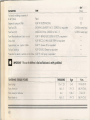
dm3
TYPE
[litres]
4 dm3 [litres)
Petrol
17,5
Engine oil sump and filter
AGIP 4T SUPERRACING
Front fork (SP)
SHOWA S.S8·AGIP F1-A.T.F. DEXRON or equivalent
3.5
0,44 (for every legs)
Front fork (CR)
Front/Rear broke and clutch circui s
MARZOCCHI Art. 550009
0,38 (for every legs)
CAPACITIES
Fuel tank, including a reserve of
or SAE 7,5
AGIP F1 BRAKEFLUIDSUPERHD DOT or equivalent
Drive chain
AGIP ROCOL CHAIN LUBESPRAYor equivalent
Speedometer, rev. counter cables
AGIP F1 Grease 30 or equivalent
Fork pin bearings
AGIP GR MU3 Grease or equivalent
Protection for electric contacts on "'le ~ame AGIP PI 160 Spray or equivalent
C
IMPORTANT - The use of additives in fuel and lubricants is strictly prohibited.
TIGHTENING TORQUE RGURES
Spark plugs
Front wheel pin
Front wheel pin setscrew
Rear wheel nut
THREADING
Kgm
N.m.
12 x 125
2+3
19.6+29.4
68.7+73.6
16x1.5
7+7.5
6x1
0.8+ 1
16x1.5
7+7.5
7.8+9.8
68.7+73.6
40
;l
OPTIONAL PARTS
At customer's request, DUCATI Motorcycles S.pA supplies a series of optional parts for this model. The table below listsa description
of available optional parts as well as the part no. for ardering them from our "Spare PartsService". Far fitting them on motorcycle, contact
our "Technical Service Department".
PART NO.
DESCRIPTION
69920491A
Kit for conversion to single-seat version
69920371A
Anti-icing kit for carburetor float chambers
4924008
1A
564 1013
1M
Front brake lIoating disc, cost iron
CR
•
•
•
•
•
•
•
•
•
•
Front mudguard, corbon
56510131A
Rear mudguard, carbon
243 1 021 1A
Carbon clutch cover, open
243 1 022 1A
Carbon clutch cover, closed
198 1 003
Lighter clutch case
lC
SP
•
••
I
41
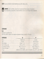
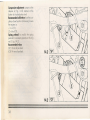
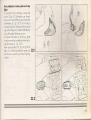
RIDING YOUR DUCATI
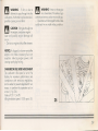
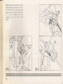
BREAK·IN RECOMMENDATIONS
First 500 km (325 miles)
Never exceed 55CJQ..-6000 rpm!
During the first hours o! service, we suggest changing engine load and speed periodicollv- do not maintain a steadly load and speed.
Under no circumstances must the engine be revved over 5500+6000
rpm.
From 500 to 1000 km (325 to 625 miles)
Avoid rapid accelerations or hig engine speeds, especially on uphills, or the mechanical components will not properly wear in with
consequent reduced Ii e.
Furthermore, inspect drive chain, lubrico:e "t and, if necessary tighten it, olten.
From 1000 to 2500 km (625 to 1550 miles)
You moy run the engine harder, being careful, however, not to exceed 7000 rpm during the 2500 km (1550 miles) break-in period.
If you hove not made several long trips (50 miles or morel, extend the 7000 rpm limit to 4000 km (2500 miles). The more carefully
you break in your 900 Superspart, the longer he life of the engine.
c
c
42
CAUTION - During break-in, maintenance operations must be scrupolously followed.
CAUTION - If you fail to follow break-in running and maintenance instructions, your Cagiva/Ducoti
any engine damage or life reduction which results.
warranty will not cover
••
CAUTION - Maximum speed in
~
any gear should be reached only
after a correct break-in period with the
motorcycle properly serviced .
•••
tl.J
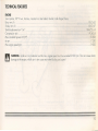
1
IMPORTANT - Never exceed
maximum engine speed in any
gear 19000 rpm). Your Cagiva/Ducati
warranty does not cover this abuse. Also,
you could cause engine failure which will
result in rear wheel lockup, or other accident.
4
17
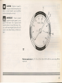
Maximum speed sectors (fig. 171-1. First 500 kin. 2. First 3000 km. 3.lVv:Jx. power roting. 4. Max.
engine rpm.
43
!$
BEFORESTARTINGTHEENGINE
(fig. 24)
1) Check fuel level in tank.
2) Check position of manual cock. The
cock shall be located on open position
(unscrew the knob) or an usual operation.
3) Sump oil leveL 0- eoe cc- oecrecsed
through ;he soecic ·"CCC'
ced
right side 0: ~e e~g·"e CO" ccse. his
level musrcome oe veen+e '
c o
MAX. notcnes prin ed on he 0 c-e nea'
the indicator.
4) Check tyre inflation pressure (Seec~ ~e
Inflation Pressures}.
5) Adjust rear and front brake cccorci g
to load and road conditions.
6) Starting switch key to "ON" posifio
(fig. 32)
•••
WARNING'
Failure 0 perfor~
hese chec, e ery aaf oe:ore
you ride may resu··n ser'ocs oo ncqe o-o
severe occioeor.
D
••
CAUTION - Do no' rur 'he motor•••
eye e un;i you now me mo oreycle has enougn engine oil.
44
18
STARTING THE ENGINE
Shih choke control lever over -A. (fig.
19.11. Moke sure thot the switch .B. (fig.
19.21 is on -RUN. position, then press the
start push-button «C. (START, fig. 19.21.
As soon as engine is started, do not
occelerate heavily to ensure an adeguote
oil warm-up and circulation in every lubricoting point.
Returnchoke lever to rest position.
In any case, ovoid harsh accelerotions .
•••
t.:.J
Let motor start spontoneously,
without octing on the throttle grip.
19.1
NOTE - No choke is needed when engine
is warm .
•••
WARNING - ever run the engine in 0 closed oreo. Theexhaust
contoins poisonous carbon monoxide gos.
t.:.J
••
CAUTION - The oil pressureworn•••
ing light should go off a few seconds aher the engine starts.
If the light stays on, stop the engine irnmediotely ond check engine oil level. Do
not operate the engine with insufficient oil
pressure.
19.2
45
••
CAUTION· Do not use electric
~
starter for more than 5 seconds at
a time. Allow 10 seconds before using it
again.
RIDING THE MOTORCYCLE Ifig. 20)
1) Desengage the ctuch operating he
control lever.
21 Depress the gea' e er 'i your oes
insert the 1 st gea' ne e.er '/ soring
back to is origino DOS' ion.
3) Accelerate gently operonnq : e COf1~o
hand grip while releasing slo
+e
clutch lever. The motorcycle wil s:a~
moving.
41 Release the clutch lever completely ana
accelerate.
51 To shift to second gear, close thethro e
to reduce engine speed, pull the clutch
lever, raise the gear lever and release
20
the clutch control lever. The same proGear position· N = Neutral
cedure should be used when shi ing to
3rd, 4th 5th or ·op gear.
To downshil], close e r01e au ille
clu ch Ie er, open the thror e rno en'ar"ly,
to ease syncnronization, downshi+ono release the clutch. When riding on uphill do not hesitate to downshih to avoid stressing the whole
motorcycle abnormally and not only the engine.
46
c
m
c
CAUTION - Avoid ropid occelerations which may flood the carburetors and stress the transmission.
Don't keep the clutch lever pulled unnecessarilywith a gear engaged. Thiscauses clutch heating, which resultsin abnormal wear.
WARNING - Do not downshift when travelling at a speed that would force the engine to overrev in the next lower gear, or
cause the rear wheel to lose traction.
CAUTION - Do not shift gears without disengaging the clutch and closing the thro·· e. "'he eng·ne cou d be damaged by
overspeed and shock.
BRAKING
Braking should be gentle using engine braking first, by closing the throttle, then using me
underinflated tires decreose braking efficiency, and increase wear.
"-C"- c-id
rear brakes. Also remember that
STOPPING THE MOTORCYCLE
By closing the throttle grip a smooth and gradual slowing down is obtained. Then downs":" ~e fiec's ~'og'ess-ve
0 neutral,
when brake application will stop the motorcycle completely. To switch off the engine turn +e e. . ocs -' ~.~
stool- (fig. 3.2).
c
m
CAUTION - Never leave the key in "ON" position when engine is off, in order
·0
avoid camage to coils.
WARNING - When riding in wet ar rainy conditions on loose surface, the ability to maneuver and stop will be reduced.
- All of your actions must be smooth under these conditions.
Sudden acceleration, braking or turning may cause loss of control.
Far safety, exercise extreme caution when braking, accelerating or turning.
- lock the brakes and cause the tires to skid. When turning a corner it is better not to brake at all, but if this is unavoidable, use light,
cooordinated braking action.
47
---
---
--------------
•••
t.!.J
WARNING - Independent use of
only thefront or reor broke reduces
stopping performances.
- When descending a long, steep grade,
use engine compression braking, with intermittent use of both brokes.
Continuous bra keopplico'ion con overheat
the brakes and reduce -reir e ectiveness.
PARKING
Alter stoopi g -'e
-o'C'\ _ e .;se +e side
stand 0 supoor +e ~o- C,'C€ v. e
par ed.
To avoid rheh, locc the hona eoc- 0pushing in and turning the ignitio
<ty iO
the "LOCK" position (fig. 211·
If parking inside a garoge or other srructure, be sure it is well ventilated and the
motorcycle is not close to any source af
flame or sporks; this includes any appliance
with a pilot light.
•••
t.!.J
WARNING-Gasoline isextremely
flammable and can be explosive
under certain conditions.
••
CAUTION - Do not pork on a salt
•••
or steeply inclined surface or the
motorcycle may fall over.
48
21
ANTI-THEFT TIPS
• Always lock the steering and never leave the key in the ignition switch.
• Be sure the registration information for your motorcycle is accurate and current.
• Park your motorcycle in a locked room whenever possible.
• Putyour name, address, and phone number in this Owner's Manual ond keep it on your motorcycle a all times.
NAME.
ADDRESS
PHONE NO
.
VEHICLE IDENTIFICATION NO.
WARRANTY START DATE ..
ENGINE DISPLACEMENT.
49
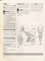
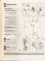
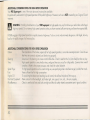
ADDITIONAL CONSIDERATIONS FOR HIGH-SPEED OPERATION
Your 900 Supers port is one of the most odvanced motorcycles available.
It is particularly well suited to high-speed operation off the public highways. However, such use is NOT covered by your Cagiva/Ducati
warranly.
•••
tl.J
WARNING - Handling characteristics of your 900 Supersport. at high speeds may vary from those you are familiar with at legal
highway speeds. Do not aHempt high speed operation unlessyou have received sufficient training and have the required skills.
NEVERengage in high-soeed operation on public streetsor highways. To do so is not only extremely dangerous, and illegal, but very
bad for the public 'rnoqe 0' a motarcyclists.
ADDITIONAL CONSIDERATIONS FOR HIGH SPEEDOPERATION
Brakes:
Steering:
Tires:
Spark Plugs
Fuel:
Engine Oil:
Electrical Equipment:
Miscellaneous:
lle impo a'lCe 0' he brakes, especially far high speed operation, cannot be overemphasized Check to see
hat they are correctly odiusted ond functioning properly.
Looseness in -'Ie s·eering can cause control difficulties. Check to see that the fork turns freely but has no play.
High speed opera ·on is very hard on tires, and good tires are crucial for riding safely. Exomine their overall
condition, inRa·e ·0 the proper pressure, and check the wheel balance.
Far high-speed operation such as rood rocing use, use spark plugs one ar two heat range [s] colder than stock.
Have sufficient fuel for high consumption.
To avoid engine seizure and resulting loss of control, the oil level must be all the way up.
Make certain that 'he heodlight, toil/broke light, turn signals, horn, etc., all work properly.
Check to see that all nuts and bolts are tight and that all safely related components are in good condition.
50
••
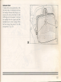
MAINTENANCE
TOOL KIT
The wrench and tool kit for normal maintenance and checks by the useriscontained
in a tool bog located in the comportment
under the seat.
To reach this compartment, the seat must
be removed as described on page 29.
The tool bag holds (fig. 221
11 Box spanner for spark plugs.
21 Tommy bar.
31 Screwdriver.
41 Operating instructions booklet.
Il
1
2
3
4
22
51
MAINTENANCE SCHEDULE
Good maintenance ensures long life to your motorcycle. The initial (1000 km/600 miles] maintenance is particularly important. Follow
these schedule and you will enjoy the moximum service life from your 900 Supersport. If your motorcycle is used mainly in city traffic
conditions, dusty territory, prevailing hilly roods, long motorway trips at high speed or under adverse climatic conditions, the operations
which ore due at normol intervals should be performed more frequently. All the operations required have been reported on the chart
of the following pages .
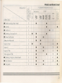
• This mark indicates that the operation should be entrusted to CAGIVA/DUCATI Service Network where high trained personnel
and special equipment are available.
~§2 .
a..
<Cu-~
""Z>-(/)
it'
~OPERATIONS
• Brake and clutch controls
Flexible control cables
OQ
C
C/l
Tyres: wear and pressures
C
• Steering bearings play
C
Drive chain .ension ond a'ig me...·
C
• Broce oods weor
• Wheel hub beorinqs
52
CIS
C
PERIODIC MAINTENANCE CHART
* ODOMETER READING Km (mil
EVERY
Aher the Iirsl
::::J
fLlJ
~
•
•
•
•
•
g8
~s
•
•
•
•
•
•
88
~~
•
•
•
•
~§
gO
N~
~s o~
88
.0
000
M=,
Refer
to
page
•
•
~5
:?:~
LlJ
30
•
Zo
OLlJ
f-
57
PERIODIC MAINTENANCE CHART
* ODOMETER READING Km [mil
.
~~~
""2>-
c./)
OQ
~OPERATIONS
• Flexible coupling
of rear wheel
P
• Fronl fork oil
S
• Tighlening
C
• General
of nuts and bolts
lubriticotion
l
Battery electrolyte level
C
Engine oil level
C
Engine oil
S
Engine oil filter
S
Intake engine oil filter
P
• Tightening
C
of engine cylinders heads
::J
IUJ
<Q
• Valve clearance
C
• Timing belts
C
Refer
o-18~
88
C!
...:.:2.
es
g8
...:s
•
C
• Fuel lank
EVERY
CL
«o::~
~
Aher the first
•
•
•
•
•
•
•
•
•
•
•
I
•
•
•
I
"'='
8°
08
•
•
•
~~
UJ
I
3i
•
I
37
~~
•
•
•
Zo
Q~
~::;
'0
ocge
0'"
n=.
~"
•
I
ci~
•
I
I
g8
I
5,0
56
•
56
41
20
•
•
•
•
•
•
•
53
ZQ~
-0
=<;co
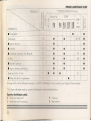
PERIODIC MAINTENANCE CHART
* ODOMETER READING Km (mil
~
::::)
<~~
f==r
w
;O::ZU) tIJ
8~
~
EVERY
88
~~
8
88 8° 8
88 ~~
dg
,..;.:9-
Spark plugs
~
~
• Ignition odvance
= --
• Fuel filter
::::,'=
• Corbureror: syncroniz. and idling odi.
~
~ ~
~
~
~
Air filter
• Engine oil pressure
-
• Engine cylinders compression
-
Brake and clutch oil level
-
• Brake and clutch oil replacement
0-
cc
=.,- -::
*: For higher odometer readings, repeat a' +e :"ec,,;:;-::
•
•
•
•
•
•
•
•
•
and cdjustrnent
L - lubrihcotion and/or greasing
54
N=:'
•
M=:'
•
•
•
•
•
•
•
--.,;--_ es-aolished here.
P - Cleaning
5 - eplacement
Refer
to
page
40- 58
59
58
61
•
--;;-:::'lCe is not covered by your Cagiva/Ducati
Operation identification symbol:
C - Chec
ci~
-
r.r
~ -
• Timing belts
Damage which can be atlributed to improper
Afler the first
o;
warranty.
Zo
Ow
~~
~~
w
•
•
•
•
•
•
•
•
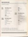
EMISSIONS
MAINTENANCE
SCHEDULE
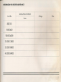
The following operations ot the following intervals mustbe carried out in order that your new Ducati motorcycle will remain in complionce
with applicable emission regulations:
500 Km
(310 mil
4.500 Km
(2.800 mil
Check and adjust as necessary:
valve tappet clecrance
timing belt tension
cylinder & head bolts & nuts torque
idle speed
carburetor synchronization
idle CO
Replace:
engine oil and filter.
Check and adjust as necessary:
valve toppet clearance
timing belt tension
cylinder & head bolts & nuts torque
idle speed
.
carburetor synchronization
idle CO
Replace:
engine oil and filter
Clean:
air filter
10.000 Km
(6.000 rni]
Check and adjust as necessary:
alve tappet clecrcnce
'iming belt tension
0. . der & head bolts & nuts torque
- s sceed
RepkKe:
e"9-~e
0
C':'C'-
'e'
c'''::'e''
spar plugs
Every 5.000 km (3000 miles! therecfter - repeat 4.500 km (2800 miles! service.
Every 10.000 km (6000 miles! thereafter - repeat 10000 km (6000 miles! service.
This is the schedule of maintenance you must follow in order to keep your emissions control system warranty in effect.
55
MAIN MAINTENANCE
OPERATIONS
ENGINE OIL AND FILTER(fig, 231
In order for the engine, trasmission, and
clutch to function properly main ain the
engine oil at the praper eve and charge
the oil and oil filter 'n cccorconce w"h the
Periodic Main enance C orr. 0' a
do
dirtandmetalparicesco
ectnne oi au'
the oil itself loses is lubricative quanti ,!
used too long,
Oil is replaced by discharging the usea
one from sump through plug (31, Then
clean gauze filter(41to removeany residue s
and refit plug tightening it deeply, Remove
the filter cartridge (51and replace it with a
new one, being careful to oil the seo..
Tighten cartridge in its seat, locking i by
hand, Undo plug (11 and refill with fresh oi
of the recommended rype (see'Capacities
toble], up 0 the indicotor eve (2 '
•••
t1.J
WARNING - Motorcycle opera-
tion with insufficient, deteriorated,
or contaminated engine oil will cause accelerated wear and may resultin engine or
trasmissian seizure, accident, and injury,
23
56
2
1
•••
CAUTION - Racing the engine
•••
before the oil recches every port
can cause engine seizure,
4
3
5
r
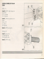
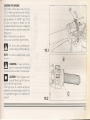
CHECKING DRIVE CHAIN TENSION AND
CHAIN LUBRICATION (fig. 24)
The drive chain must be checked, adjusted, and lubricated in accordance with
the Period ic Ma intena nce Chart, for Safety
and to prevent excessive wear.
The chain must be at a min. distance of
20+30 mm/0.78+ 1.18 in. from the fork,
with wheels contacting the ground and
without pilot
Proceed as follows (SPversion):
using a 22 mm wrench, loosen nut (1) fixing
the rear wheel axle. Using a 10 mmwrench,
loosen the nuts(2) and, operate on the screw
(3) to obtain a correct chain tension and
wheel alignement; then tighten the nut (2).
Proceed as follows (CR version):
using a 10 mm wrench, loosen nut (1)
fixing the rear wheel axle. Operate on the
screw (2) to obtain a correct chain tension
and wheel alignement; then tighten the nut
(1) checking for correspondence, on both
fork sides, of the positioning notches.
Check that the nuts (4) securing the crown
to the flange are tight This operotion can
also be carried out with the wheel fitted, by
inserting an 8 mm universal socket wrench
from the opposite side to hold the pins firm
in correspondance to the above nuts.
24
~
20"'30mm I0.1H.18in.)
57
•••
WARNING-Misalignementofthe
wheelwillresultinabnormalweor,
ond may resultin an unsaferiding condition.
- If the axle nut is not securely tightened,
an unsafe riding condition moy result.
W
••
CAUTION -Insufficien chain play
will overload the Transmissionand
engine; keep the ploy ·'')i'! - e soecdied
limits.
U
0.6mm
(0.023 in)
25.1
SPARK PLUGS (fig. 25.1)
Use the standard plug ar equivalenr:
CHAMPION - RA 6 HC
Electrode gap: 0,6 mm/O,023 in.
The spark plugs should be removed periodically in accordance with the Periodic
Maintenance Chart for cleaning, inspection, and resetting of the plug gap.
••
U
CAUTION - Never use a sparK
plug with an improper heat range,
or of improper thread length_
- Thespar plug mustbe secure ·gh-ened.
An improperly tightened plug can oecorne
very hot and possibly damage the engine.
Tigh ening torque:
19,6+ 29,4
m
2.,.3 g-m
14,5.,.22 ft-Ibs
58
25.2
AIR CLEANER ELEMENT (fig. 252)
The air cleaner element must be replaced
in accordance with the periodic Maintenance Chart. When riding in dusty areas,
more frequent service may be necessary.
To remove the filter, proceed as follows:
-
lift the tank
remove the cover (1) through the proper
hooks.
- extract the filter cartridge (2).
Clean the filter cartridge though a compressed air jet or, if necessory, replace it.
•••
WARNING - If dirt or dust is
allowed to pass through into the
carburetors, the ihronle may become stuck,
possibly causing an accident.
m
•••
m
•••
WARNING-Never runthe engine
in a closed area. The exhaust gas
contains poisonous carbon monoxide gas.
- Operation with damaged throftle cable
could result in an unsafe riding condition.
m
CAUTION -If dirt gets through into
the engine, excessive engine
wear and possibly engine damage will
occur.
- Do not run engine without filter element.
NOTICE: A clogged air cleaner restrictsthe
engine's air intake increasing fuel consumption, reducing engine power, and
causing spark plug fouling.
CARBURETOR IDLE SPEED ADJUSTMENT
The carburetor idle speed is set at the
factory for maximum performance and
compliance with emissions regulations,
and is sealed to prevent adjustment.lf necessary, to perform this operation act on
screw 11, fig. 261
Index of
1,5.,.2%
Idling revolution speed: 1300 rpm ± 50.
co:
26
59
The terminals of the accelerator and choke
cables must have a clearance af 1,5-~2,0
mm/0.06+0.08
in.; if necessary, use the
praper adjusters next to the control (2, fig.
27.1) on the handlebar and to the
carburetor (3, fig. 27.2 only for accelerator).
27.2
60
27.1
FRONT AND REARBRAKE
The front broke fluid level must be above
the mark «MIN· indicated on reservoir (fig.
28.1 for SP, fig. 28.2 for CR)
The rear broke fluid level in the reservoir
mustbe kept between the upper and lower
level lines.
There are no adjustments to perform, but
fluid level must be inspected periodically,
and system inspected or fluid leaks in
accordance with the PeriodicMaintenance
Chart.
••••
WARNING-If the brake lever free
travel becomes excessive and
the brake pads are not worn beyond the
recommended limit there is probably air in
the brake system and it must be bled out.
[1.J
••.•
WARNING - Brake fluid may
cause irritation.
Avoid contact with skin or eyes. In case of
contact flush thoroughly with water and
call a doctor if your eye were exposed.
[1.J
••.•
[1.J
WARNING - If the brake lever
feels mushy when it is applied
there might be air in the brake lines or the
brake may be defective. Since it is dangerous to operate the motorcycle under such
conditions, have the brake checked immediately by an authorized Cagiva/
DUCATI dealer.
CAUTION-UseonlyDOT4brake
fluid from a sealed container.
- Handle brake fluid with care because it
can damage point and instrument leses.
- Never allow contaminants (dirt, water
etc) to enter the brake fluid reservoir.
- Do not mix two brands of fluid. Change
the brake fluid in the entire brake system -,
you wish to switch to another fluid brand
[]
28.1
CLUTCH
Your 900 Supersport has a hydraulico
operated clutch. The clutch systemmust De
inspected periodically for fluid level a
leakage. The clutch oil level mustbeaoo e
the mark «MIN· indicated on the reserve!-
••.•
- Clutch fluid may
cause irritation .
Avoid contact with skin or eyes. In case of
contact, flush thoroughly with water and
call a doctor if you eyes were exposed.
[1.J
WARNING
61
TO REPLACE THE BULBS
When replacing a bulb, make sure that the
new one is identical with that it replaces
and voltage and wattage are as specified
on page 35, Electrical System.
Headlamp (fig. 29)
To gain access to the headligh bulb, if
necessary to operate in me interior a! t e
fairing. Disconnect 'he electrico cables
from the bulb base.
Rotate the bulb-holder in counierdoc
ise
direction and mo e it free from the reRector, remove the blown bulb and replace
witha newone. Be carefulto grip the new
bulb at the base only without touching
the transparent body with the fingers or
the bulb efficiency will be adversely affected.
Insertthe bulb locating lugs into the associated seats to have a correct beam oirninq.
Refit the spring retainer while pressing e
lugs and turndoc wise until i' is fully ho e_
Connect the terminals previou t isconnected.
62
29
Instrument
cluster
To replace the warning lights bulbs on the
instrumentcluster, it is necessary to remove
the headlight. Remove the fairing by unscrewing the screws which fasten it to the
half-fairings and to the support. To remove
the headlight from the support push the
headlight down in order to release it from
the three clamps, then extract it from the
springscrews (1, fig. 301.
30
63
Disconnect the feeding connector and
remove the closing cover on the cluster
bockside. Unscrew the two fastening screws
(2, fig. 31.1) and extract the panel containing the bulb-holders. Arronge replacement of the bulb, extrocfinq if from its bulbholder. Benehath every instrumem in he
cluster there is a bu D. To arrange its
replacement it is necesscry to extrac the
bulb-holder con aining it underneath the
instrument. Extract lamp (B, fig. 31.2) and
replace it with another of the same type.
Insertand rotate it inside the bulb-holder (A,
fig. 31 .2), then insert the assembly inside
the instrument seat.
64
Turns indicators, license plate and stop
lights
To reach the front indicators, loosen the
screw (1, fig. 32.1 )fixing the cup. Extract
the cup from the half-fairing and extract the
bulb-holder (2, fig 32.1) by turning it
counterclockwise Replace the bulb pushing and rotating it in itssaddle. Refitthe cup
using the proper fastening screws.
To renew the bulbs of remaining lights
simply remove the crosshead screws securing their lenses (1, fig. 322).
Then replace bulbs (2-3, fig. 32.2) (all of
them are of the bayonett-base type) and
refit the lens correctly with their fastening
2
32.1
~;;;:;;;:;;;;;;;;:;;;;=:;;;;;;;;;;:==~
~;:;;;:;;::::==;:;;;~~;;:;==~
screws.
65
HEADUGHT ALIGNMENT
Periodically check head lamp alignment,
as follows:
- bock the motorcycle 10m. (393 in.]
from a vertical wall (fig 33.1);
- ensure that ground is flat and optical
axis of head lamp is perpendicular with
respect to the wall;
- the motorcycle should reston both whee s
(not on stand);
- measure the centre headlamp height
from the ground and drawa cross at he
some height on the wall;
- switching on the traffic beam, the
boundary line between the dark zone
and the lit zone musthave an height not
over 9/1 0 of the height from the ground
of the headlomp centre;
The possible correction of the vertical
headlight direction can be performed by
turning the adjustment screw (1, fig.33.2)
after having removed the fairing.
To adjust the horizon a dlsplocernerr rurn
the screws (2, fig.33.2).
33.1
33.2
66
MOTORCYCLE CARE
Periodically, clean the motorcycle, keeping in mind the following:
- Clean the engine using a nonflammable solvent or 0 proprietary engine
cleaner, and dry with a clean cloth.
- Sponge down the painted parts of the
framewith water and drywith a chornois
or soft towel.
- Never use solvents, petrol, alcohol or
paraffin to avoid damaging
the
paintwork.
Be coreful not to wet electrical connections or control units and coils.
•••
m
WARNING- Braking performance
may be impaired Immediately
after washing the motorcycle.
- Never wax or lubricate the brake discs.
Lossof braking and an accident could
result.
- Clean the discs with an oil-less solvent
such as acetone or trichloroethylene.
•••
CAUTION - Do not use steel wool
•••
or a cleaner containing abrasives
or compounds to clean the wheels, as they
cause damage.
•••
m
WARNING - Many solvents and
•••
CAUTION - Avoid using any ol-
-
cleaners are highly flammable or
nisuly toxic. Always follow the manufacturer's instructions and cautions. Avoid
skincontact or breatnins vapors. Follow
instructions for gasoline on page 40.
e sure the igni-er +e engine is
•••
kaline or strong acid cleaner,
gasoline, brake fluid, or any other solven
on painted, plastic or rubber parts.
CAUTION - Excessive washi 9
•••
pressure may cause worer seeoage and contamination of whee oecings, front forks, brakes and trans ·SS-(Y
seals. Improper application of hig oressure washers has resulted in manyexpensive unnecessary repair bills. Avoid the
typ~ of pressure washer available in coinoperated car washers.
-es- +e ere -e
:: ...aoce" s and to
-c e -e - --=e.: ;::a::- -= --e ground.
De- _-05 -05 --es
•••
STORAGE
If the motorcycle is to remain inactive over
long periods it is advisable to carry out the
following operations:
- clean the motorcycle;
- empty the fuel tank;
remove the spark plugs and introduce a
few drops of engine oil in the cylinders,
then rotate the engine by hand, uSing
the rear wheel, to distribute a protective
film of oil on cylinder walls;
...--e -::--
•••
WARNING-Gasolineisextremely
flammable
and
IS explosive under certa in conditions. Do not smoke
or allow flames or sparks near the equipment while draining fuel.
m
67
The descriptions and illustrations appeariang in this Manual are not binding. CAGIVA NORTH AMERICA. Inc. & DUCATI Motorcycles
S.p.A., therefore, reserves the right - while retaining the basic features of the Model herein described and illustrated - to make at any
time, and without necessarily bringing this Manual up-ta-date, any alteration to units, parts or accessories deemed expedient for any
technical, manufacturing or commercial reason.
CONSUMMER INFORMATION
VEHICLE STOPPING DISTANCE ON DRY PAVEMENT
Thistable indicates bra ing performance that can be met or exceedec by the vehicles to which it applies, without locking
the wheels, under different conditions of loading.
The inlorrnotion presented represents resultsobtainable by skilled riders under controlled road and vehicle conditions,
and the information may not be correct under other conditions.
Descrip ion of ehicles to which this table applies: 900 Supersport
68
STOPPING DISTANCE
(feet)
VEHICLE
TEST
SPEED
M_P_H_
limit
test result
limit
test r. (front)
test r. (rear)
30
L3
24
97
54
70
60
185
127
388
282
326
80
345
225
689
553
605
service brake system
partial service brake system
CAGIVA UMITED WARRANTY ON EMISSION CONTROL SYSTEM
Cagiva North America, lnc., 5 Washington Avenue, FAIRFIELD,NJ 07004 (hereinaher "Ccqivo"] warrants that each new Cagiva/
Ducati motorcycle manufactured on or olter Jonuary 1, 1978, thot includes as standard equipment 0 headlight, taiHight and stoplight,
and is street legal:
A.
is designed, built and equipped so as to conform at the time of initiol retail purchose w"" a CD "CODeregulations of
the United States Environmental Protection Agency, and the Colitornio Air Resources Boc-o C'X: s :"'ee:"'o defects in
material and workmanship which cause such motorcycle to fail to conform with coo "co e 'SSv -.--.,,;:;
vn"'ee States
Environmental Protection Agency or the California Air Resources Boord for a oerioc ci..se ::eoer. -:;::;r -ne engine
B.
displacement,of 12"000 kilometers (7.456 miles], if the motorcycle's e g"-e cis ~:e-er
s jess
-" 70 cubic
centimeters; of 18.000 ilometers (11.185 miles], ifthe motorcycle's enq'ne c"s=ce-~
s =_::: _:, :;-5C""e'""'1On
170
cubic centimeters but less than 280 cubic centimeters; or of 30"000 "ome"e's - E v-"
c ce s engine
displocement is 280 cubic centimeters or greater; or five (51years fron' e ~~'e:::- - _
crever first
occurs.
-=
-= - __
=_ __-~
I.
-
COVERAGE. Warranty defects shall be remedied during customary business
- -' -- --located within the United States of Americc in compliance with the Clean Ai' r-« ~-- ccc ::.:;-oe e:. _ - _:- -e _- -eo Srotes
Environmental Protection Agency and the California Air Resources Bocrc. k :x;- ':X;-s e- J:-'='- - :. -'
become the property of Cagiva.
In the state of California only, emissions reloted worranted ports are speci'ico y definec
-" s
5 ::-"ss crs
C'Tar;y Po s
list. These warrantee parts are: carburetor and internal parts; intake mar"fod" fuel injection sys-e-: spork advance mechanism;
crankcase breather; air cutoff valves; fuel tank cap for evaporative emission controlled vehicles; pressure control valve; fuel/vapor
separator; canister; ignition points mounting plate; pulsing coils; igniters; breaker governors; ignition coils; ignition wires; ignition
points, condensers, and spark plugs il Ioilure occours prior to the first scheduled replacement, and hoses, clamps, fittings and tubing
used directly in these parts. Since emission related parts may vary from model to model, certain models may not contain all of these
parts and certain models may contain functionally equivalent parts.
In the state of California only, Emission Control System emergency repairs, os provided for in the California Administrative Code,
may be performed by other than an authorized Cagiva dealer.
~-=
69
II. LIMITATIONS. This Emission Control System Warranty shall not cover any of the following:
A.
Repair or replocement required as a result of III accident, 121misuse, 131lack of reosonable and proper maintenonce,
141repairs improperly performed or replacements improperly installed, 151use of replacement paris or accessories not
conforming to Cogiva specifications which odversely affect performance and/or 161use in competitive racing or related
events.
B.
Inspections, replacement of paris and other services and adjustments required for routine maintenance.
C.
Any motorcycle on which odometer mileage has been changed so that actual mileage cannot be readily determined.
III. LIMITED LIABILITY.
A.
The liability of Cagivo under this EmissionControl SystemsWarranty is limited solely to the remedying of defects in material
or workmanship by an authorized Cagiva motorcycle dealer at its place of business during customary business hours. This
warranty does not cover inconvenience or loss of use of the motorcycle or transportation of the motorcycle to or from the
Cagiva dealer. CAGIVA SHAtl OT BE LIABLEFOR ANY OTHER EXPENSE,LOSS OR DAMAGE, WHETHER DIRECT,
INCIDENTAL, CONSEQUE
OR EXEMPLARYARISI G I CONNECTION WITH THE SALE OR USE OF OR
INABILITYTO USE THE CAGt A/DUCATI MOTORCYClE FOR ANY PURPOSE.SOME STATESDO NOT ALLOW THE
EXClUSION OR LlMITATIO OC A Y INCIDENTAL OR CONSEQUENTIAL DAMAGES, SO THE ABOVE LIMITATION
OR EXClUSION MAY NO~ APPLYTO YOU.
B.
NO EXPRESSEMISSION CO ~ROLSYSTEMWARRANTY ISGIVEN BYCAGIVA EXCEPTAS SPECIFICALLYSETFORTH
HEREIN. ANY EMISSIO CO TROL SYSTEMS WARRANTY IMPLIEDBY LAW, INClUDING ANY WARRANTY OF
MERCHANTABILITY OR FIT ESS FOR A PARTICULARPURPOSE,IS LIMITEDTO THE EXPRESSEMISSION CONTROL
SYSTEMS WARRANTY TERMS STATEDIN THIS WARRANTY. THE FOREGOING STATEMENTS OF WARRANTY ARE
EXClUSIVE ID I LIEUOF ALLOTHER REMEDIES.SOME STATESDO NOT ALLOW LIMITATIONS ON HOW LONG
AN IMPLIEDWAf?RAi ;ry LASTSSO THE ABOVE LIMITATION MAY NOT APPLYTO YOU.
C.
No dealer is authorizeo 0 modify this Cagivo limited Emission Control Systems Warranty.
IV. LEGALRIGHTS. THIS WARRANTY GIVES YOU SPECIFICLEGALRIGHTS, AND YOU MAY ALSO HAVE OTHER RIGHTS WHICH
VARY FROM STATETO STATE.
V. THIS WARRANTY IS IN ADDITION TO THE CAGIVA LIMITED MOTORCYCLE WARRANTY.
70
MEMORANDUM ON ROUTINE MAINTENANCE
CAGIVA/DUCATI
SERVICE
km/miles
Doe
Mileage
Name
500/310
1.000/620
10.000/6000
20.000/12000
I
30.000/18000
40.000/24000
i
71
ElECTRICAL SYSTEM SCHEME
72
The oil temperature
indicator (36) and the oil temperature
(30)
o ~~~
It>
W/R
R
C/Bk
Y
CIA
o+-<l
OFF
ON
®9
RIB
Ti
W/G
-
®
[r';1 l-;-~f~-U ~ b~"-e
~f- ~wl
o-'
::t.,
I
~~
n/UI(-
••
I
jO
"'Cb
GIc=::JO
il
LBN-
W/R
HI
C';':::). B
'--
BN---+<>+--+-+-I-+-------,
~
O/Sk
IBK-+-O_+_+-i~--+--___,
0
IBK-+o-+--+-if------f-f----+-+-------'
IBN
-+-O--t--'
W
LB---+<>-+--~---_+_+------,
IB-+-c~------+-t---l-__+---.J
R
IR-+-c_+_-----+,
W
G
R/R-+O-+------..--+++-+---+---
-e-
®
-
,---R/B
R
v
IBK-+-o_+_-'-----,
IG-+-c~----+-_+_-++t---l-__+--+-<:>-+------+--+--H+-+---I-W
IB<+-O+-----+-+---+++-+---+---
".
--+------'
GR/R~
WIG
W
Y
~W/BK
OR/R
~
W/BK-----'
I~@
GR-+CH------,
Y
WIG
G
Y
W
W/BK
00
f"" ~
eJ'
r---q.'"
'!::
r,
GR-
~/BK-
I
~BK
W/G-
1
1
iII_~
8Ny-
e
1
o
I
=
IQ[QIQIID
J.
y
B
O/Sk
'T'NI ~
, 1'1'1." 'i"~
*BIBK
~I
o
~
YUASA
+--------f-o
B/8K
W~~'"
@IQlQIID
+
®
YB16AL -A2
~
R
@
QE:l
TI'1,'.i., .-.' u-
18~·~7
-
. .
@
Otl-
V/BK
•• ceo
(37) are only for "SP" model.
/01
I
<;>--1-0
transmitter
VlG-
II~
I
P
LB
iA;~u~m~
~"' ~.
(1~
OR/R
@
VI"
~
@
IG-+-O+---....,
'-----~-
BN
----,
<0
---'w
~
0
--L
:-J
G>
m-g
~a
~iS
o·
"'<...
-I»
...• '"
l'lc
",I»
n-<
=t'_
~l!!
c
D-
6"
9
0
I»
.~
"&
~5
«,
.,!1.
;;
g
;;;
9:
in
;;;
~
5
~
Uffici Commerciali Amministrativi:
BOLOGNA - VIA A. CAVALIERI DUCATI n. 3
Tel. 051/405049 - Telex 510492 DUCMEC
Telefax 051/406580