1
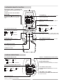
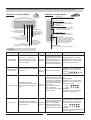
USER MANUAL CONTROL OLR-1X English/02-2005 TABLE OF CONTENTS CONTENTS PAGE 1 1 1 2 2 3 4 5 5 6 SYSTEM CONFIGURATION HOW TO INSERT BATTERIES HOW TO USE THE REMOTE CONTROL INFRARED REMOTE CONTROL DISPLAY INDICATORS OPERATION PROGRAMMING ADJUSTMENT RECEIVER INDICATORS ALARM UNIT PROTECTION DEVICES SYSTEM CONFIGURATION This control is valid for operating as a cooling only or heat pump application. The control for the indoor unit is the same for operating with outdoor units cooling only or heat pump. The indoor unit should be configured prior to making the electrical connections, by setting the switch for heat pump or for cooling only unit . For further details, follow the OPERATION AND SERVICE MANUAL in the indoor unit. HOW TO INSERT BATTERIES USE 2 AAA LR3 TYPE 1,5V ALKALINE BATTERIES. AUTO Push the cover of the wire less remote control and slide it to remove. Insert batteries in the compartment, paying special attention to the correct polarity indicated in the battery compartment. H M L °F °C Replace the cover. CAUTIONS Life of batteries is about 12 months under normal conditions. If the remote control does not work, or it only works near the unit, the batteries must be replaced. Never use used batteries. Always use the same type of battery. FAN MODE The batteries must be removed from the remote control if not used for a long period. Remove batteries if not used for long period HOW TO USE THE REMOTE CONTROL Direct the remote control transmitter towards the unit receiver window and enter choice on the controller. A "beep" will indicate that the signal has been received. The unit will not respond to the control signal if there is an object between the remote control and the unit. The maximum operating range for the remote control is approximately 7 meters. 1 INFRARED REMOTE CONTROL INFRARED SIGNAL TRANSMISSION Input signals to the air conditioner are sent from here. TEMPERATURE ADJUSTMENT BUTTONS Used to select the desired temperature. Pressing the or buttons will increase or decrease the required room temperature value. LCD DISPLAY AUTO H M It indicates operation modes, setting temperatures and time programming. L °F ON/OFF BUTTON °C Press the button to start the unit, press it again to switch it off. MODE BUTTON Press it to select the operating function: COOL, HEAT, DRY, FAN, AUTO. FAN SPEED SELECTION Select between ventilation speeds (high, medium, low, and automatic). HIGH H L FAN MODE FAN SWING SLEEP ON OFF CLR CLR MEDIUM M AUTO AUTOMATIC LOW COOL HEAT DRY AUTO SLEEP MODE Press it to activate the sleep or energy saving mode (Not available on fan mode operation and dry mode). SWING BUTTON OFF TIMER BUTTONS Press SWING button to activate the Air Sweep function. Used to program the switching OFF of the unit at a specified time. ON TIMER BUTTONS Used to program the switching ON of the unit at a specified time. TIMER BUTTONS Used to set clock. DISPLAY INDICATORS FAN SPEED INDICATOR SIGNAL TRANSMISSION INDICATOR It indicates the fan speed selection. It indicates that the selection made on the infrared control is being sent to the unit. HIGH H L LOW SLEEP INDICATOR AUTO M MEDIUM OPERATING MODE INDICATORS It indicates the operating mode of the unit. COOL HEAT FAN It indicates that the sleep mode has been activated. AUTOMATIC AUTO H M DRY AUTO L AIR SWEEP INDICATOR °F It indicates that the Air Sweep function has been activated. °C ON TIMER - OFF TIMER It indicates that the ON TIMER or OFF TIMER mode has been selected. TIME INDICATOR It indicates the actual time. While ON TIMER - OFF TIMER selection, it indicates the time selected. 2 OPERATION 1. HOW TO TURN ON/OFF THE UNIT Press ON/OFF button to start or stop the unit. When the unit is stopped, if you press this button, the unit will start and the POWER indicator will be on. When the unit is on, if you press this button, the unit will stop and the POWER indicator will be off. 2. SELECTING THE UNIT'S OPERATING MODE The operating mode is always indicated on the display. Pressing the button MODE you can change the unit operating mode, and choose the one desired: COOL HEAT DRY COOL FAN AUTO AUTO HEAT AUTO: The system switches automatically from cooling to heating mode, depending on the ambient and desired temperature. When the unit is working on cooling mode receiver COOL indicator is on and HEAT indicator blinks. On the other hand when the unit is working on heating mode receiver HEAT indicator is on and COOL indicator blinks. COOL: The unit is working on cooling mode to reach the temperature desired. Receiver COOL indicator is on. HEAT: The unit is working on heating mode to reach the temperature desired. Receiver HEAT indicator is on. FAN: The unit is working on fan operating mode. FAN DRY: The unit is working on dry operating mode. DRY 3. SELECTING DESIRED ROOM TEMPERATURE (SET-POINT) Pressing the buttons or allow to select the desired room temperature (set-point). The button allows the increase of the current set-point. The button allows the decrease of the current set-point. The temperature range is from 16ºC / 60ºF to 30ºC / 85ºF. To change from ºC to ºF or vice versa, press the buttons and at the same time. NOTE: if we have selected FAN as the unit operating mode, the set-point can not be modified. 4. SELECTING THE FAN OPERATING MODE Pressing the button you can change the desired fan speed, according to the following sequence: FAN AUTO HIGH NOTES: - If FAN mode is selected, the AUTO fan operating mode can not be selected. - If DRY mode is selected, the fan operating mode can not be changed. L M H MEDIUM LOW AUTOMATIC - Even though LOW speed has been selected on HEATING mode, the unit protects itself changing automatically the speed. 5. SLEEP FUNCTION Press the button SLEEP to activate this function; the symbol FIG. 1 COOLING MODE FIG. 2 HEATING MODE ºC Set Point+2ºC Set Point will be displayed on the remote control. 0.5 1 Set Point -0.5ºC Set Point+1ºC Set Point -1ºC 0.5 1 2 Hours Hours SLEEP FUNCTION ON Increase the set point temperature as the above drawing shows (FIG. 1). SLEEP FUNCTION ON Decrease the set point temperature as the above drawing shows (FIG. 2). Set Point+0.5ºC Set Point 2 Set Point -2ºC ºC 6. SWING FUNCTION Press the button SWING to activate this function; the symbol will be displayed on the remote control. 7. CONDENSATE PUMP The condensate pump starts automatically to work when the compressor is working on cooling mode or when the float switch indicates overflow. 3 PROGRAMMING ADJUSTMENT CLOCK Press AM or for 2 seconds to activate; current clock setting will decrease/increase at 1 minute interval upon each press or The speed of interval updating will increase after 4 second of continuous key press or . It will update at high speed after 6 second of continuous key press or ON OFF CLR CLR 1 PROGRAMMING START UP OF THE UNIT (ON TIMER) 2 AM ON AM ON To turn on the air conditioner unit if previous status is off. 1 Press symbol ON to activate ON TIMER. While programming process, the ON ON will flash on the display. 2 The first press of ON ON OFF ON OFF CLR CLR CLR CLR button will show the previous time setting. 3 Further pressing of the button will advance the time setting in 30 minutes interval. 3 AM 2 seconds after do not press ON button, the signal is sent to the unit. You can see the actual time and 4 Press CLR ON symbol remains on the display. to deactivate ON TIMER. The symbol ON will disappear. 4 ON AM ON OFF ON OFF CLR CLR CLR CLR 1 PROGRAMMING STOP OF THE UNIT (OFF TIMER) 2 AM 1 Press symbol OFF to activate OFF TIMER. While programming process, the OFF OFF will flash on the display. 2 The first press of OFF OFF ON OFF CLR CLR CLR CLR button will show the previous time setting. 3 4 Press CLR OFF symbol remains on the display. to deactivate OFF TIMER. The symbol OFF will disappear. 4 AM 2 seconds after do not press ON button, the signal is sent to the unit. You can see the actual time and OFF ON Further pressing of the button will advance the time setting in 30 minutes interval. 3 AM OFF To turn off the air conditioner unit if previous status is on. AM OFF ON OFF ON OFF CLR CLR CLR CLR The regular use is to combine ON TIMER and OFF TIMER. ON TIMER AND OFF TIMER functions remain stored until the cancellation keys are pressed, to profit from the programming for several days. 4 RECEIVER INDICATORS AND ON/OFF BUTTON SETTING IN THE INDOOR UNIT VERSION 1 (CASSETTE MODEL) VERSION 2 (CEILING MODEL) DRY indicator It indicates that the dry mode has been selected. COOL indicator It indicates that the cool mode or automatic mode operation has been selected. POWER indicator It indicates that the unit is on operation. If no more indicators are on, the unit is operating on fan mode. RECEIVER window Remote control signals are got by this receiver. COMPRESSOR indicator It indicates that the unit is working on cooling or heating mode according the selection. COOL indicator Cool mode or automatic mode operation has been selected. POWER indicator It indicates that the unit is on operation. If no more indicators are on, the unit is operating in ventilation mode. HEAT indicator It indicates that the heat mode is selected, or automatic mode operation. ON/OFF button If the remote control is not available, press this button to stop/start the unit. Also, pressing the button repeated times, the unit operating modes could be selected according to the following sequence: OFF-COOL-HEAT. HEAT indicator It indicates that heat mode or automatic mode operation has been selected. RECEIVER window Remote control signals are got by this receiver. ALARM DESCRIPTION ANTI-FREEZE PROTECTION The unit is working on cooling mode and the indoor unit coil temperature goes below a set value. EFFECTS ACTION The unit is working and the temperature in the indoor unit The unit coil is too low: Check the will stop. selected temperature . If the alarm doesn't disappear check the correct functioning. BROKEN SENSOR Ambient temperature regulation The unit Check sensor connection. probe error. DETECTION will stop INDICATION Ceiling model: No indication. Cassette: The compressor led blinks while the rest of the leds remain the way they were. Ceiling model: Sequence: The Power led is 4 seconds on and 3 seconds off . Power: Cassette: All leds are off. HEAT OVERLOAD OVERFLOW These protections are automatic reset for the first time. To reset for the second time press button "ON/OFF" until the alarm disappears. Compressor overload. If the alarm shows up again, During heating cycle the indoor The unit please check: coil temperature has been too will stop - Indoor coil temperature high. probe connections. - Indoor unit works properly - Clean air filters. Overflow of water condensing. The float switch, has detected water Overflow. These protections are automatic reset, the alarm resets automatically when The unit there is no more water. will stop If the alarm shows again: Check the water drain, and the float switch connections. 5 Ceiling model: Sequence: The Cool led blinks while the Power led blinks once every four seconds. Cool: Power: Cassette: Sequence: The Cool led blinks while the Power led is on. Ceiling model: Sequence: The cool led blinks 5 times, while the Power led is 3 seconds off and 2 seconds on. Cool: Power: Cassette: Sequence: The Cool led blinks while the Power led is on. UNIT PROTECTION DEVICES AGAINST FREQUENT COMPRESSOR CYCLING When COOL / HEAT / AUTOMATIC is selected, the start up of the unit will be delayed for 3 minutes, to protect the unit against frequent compressor cycling. AIR PREHEATING On heating mode, the indoor unit fan will not start or will start at low speed, to prevent from air cool feeling, until the indoor unit temperature reaches the set temperature; then the unit will operate to the selected temperature. DEFROST CYCLE When the unit is operating on heating mode, the unit will do defrost to eliminate the ice that will produce the outdoor unit; on this cycle, the indoor unit fan will switch off. AUTO RESTART If power failure occurs during operation, the unit will start (after power recovery) in the same operation mode as before. 6 www.lennoxeurope.com BELGIUM, LUXEMBOURG : CZECH REPUBLIC : FRANCE : GERMANY : IRELAND : NETHERLANDS : POLAND : PORTUGAL : RUSSIA : SLOVAKIA : SPAIN : UKRAINE : UNITED KINGDOM : OTHER COUNTRIES : COD: MUL31E-1003 02-2005 LENNOX BENELUX N.V./S.A. www.lennoxbelgium.com LENNOX JANKA a.s. www.janka.cz LENNOX FRANCE www.lennoxfrance.com LENNOX DEUTSCHLAND GmbH www.lennoxdeutschland.com LENNOX IRELAND www.lennoxireland.com LENNOX BENELUX B.V. www.lennoxbenelux.com LENNOX POLSKA Sp. z o. o. www.lennoxpolska.com LENNOX PORTUGAL Lda. www.lennoxportugal.com LENNOX DISTRIBUTION MOSCOW www.lennoxrussia.com LENNOX SLOVENSKO s.r.o. www.lennoxdistribution.com LENNOX REFAC S.A. www.lennox-refac.com LENNOX DISTRIBUTION KIEV www.lennoxrussia.com LENNOX UK www.lennoxuk.com LENNOX DISTRIBUTION www.lennoxdistribution.com Due to Lennox's ongoing commitment to quality, Specifications, Ratings and Dimensions subject to change without notice and without incurring liability. Improper installation, adjustment, alteration, service or maintenance can cause property damage or personal injury. Installation and service must be performed by a qualified installer and servicing agency.