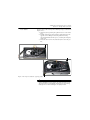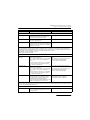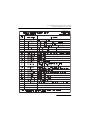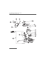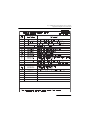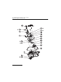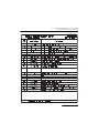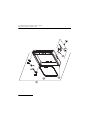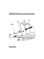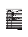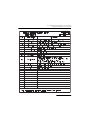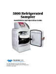
1
5800 Refrigerated Sampler Service Guide Part #69-5803-093 Copyright © 2013. All rights reserved, Teledyne Isco Revision C, April 2014 Isco 5800 Refrigerated Sampler Service Guide Safety Isco 5800 Refrigerated Sampler Service Guide Safety The Isco 5800 Refrigerated Sampler is a “definite purpose” device, intended for use only with compatible Isco equipment. Except as described in this manual, do not use this product with any other manufacturers’ equipment, or for any other purpose. Use for any purpose not described in this manual could cause personal injury or property damage. Electrical Safety The sampler requires a nominal 115V/60 Hz, or 230V/50Hz AC power. Refer to the nameplate and ratings label inside the refrigerator compartment. The power input is through the mains power cord at the back of the sampler. The sampler is protected by an internal thermal cut-out. Additionally, the sampler controller circuitry is protected by an internal fuse. WARNING Electrocution hazard. Never manipulate electrical switches or power connections with wet hands or when your feet are in contact with water. WARNING AC electrical power must meet the applicable electrical code requirements for your installation and must be provided with an earth ground connection. If necessary, consult with a certified electrician to ensure that AC power is provided in accordance with the local electrical code. The AC power cord of this device is equipped with a three-prong grounding plug designed to mate with a grounded power outlet. Grounding minimizes the possibility of electrical shock. It is the user’s responsibility to ensure that the AC power source is properly grounded. If in doubt, have the outlet checked by a qualified electrician. If the available AC power outlet only accepts two prongs, or if it is determined that the outlet is improperly grounded, the outlet must be replaced by a qualified electrician before attempting to power this device. WARNING If this device’s AC power cord is frayed or otherwise damaged, discontinue its use immediately. Never modify the power cord. A replacement power cord is available from Teledyne Isco; see Section 4.6 of this manual for more information. i Isco 5800 Refrigerated Sampler Service Guide Safety Servicing Modules Before attempting to remove and replace a module, observe the following precautions: WARNING Removing a module exposes you to electrical and mechanical hazards. Always disconnect the AC power cord before attempting to remove any module. Only trained service personnel may remove or replace these modules. CAUTION Removing the sealed modules will expose the internal components. Wet or corrosive atmospheres may attack the exposed refrigerator components. Always service modules in a dry, corrosion-free environment. CAUTION Modules contain circuit boards and sensitive electronics that can be damaged by a discharge of static electricity. Avoid touching the internal components. Only handle the module by the edges or exterior surfaces. CAUTION Electrical connectors and wires can be damaged if improperly handled. Electrical connectors must only be handled by the connector body. Never grasp the wires or use tools to disconnect a connector. Never allow a module to hang by its wiring. CAUTION Earth ground bonding conductor. Do not remove or disconnect. If this conductor must be disconnected to remove a module, it must be reconnected when installing the replacement module. General Warnings Before installing, operating, or maintaining this equipment, it is imperative that all hazards and preventive measures are fully understood. While specific hazards may vary according to location and application, take heed in the following general warnings: WARNING This instrument has not been certified for use in “hazardous locations” as defined by the National Electrical Code. ii Isco 5800 Refrigerated Sampler Service Guide Safety WARNING Avoid hazardous practices! If you use this instrument in any way not specified in this manual, the protection provided by the instrument may be impaired; this will increase your risk of injury. Additional safety information can be found in Appendix B. Hazard Severity Levels This manual applies Hazard Severity Levels to the safety alerts, These three levels are described in the sample alerts below. CAUTION Cautions identify a potential hazard, which if not avoided, may result in minor or moderate injury. This category can also warn you of unsafe practices, or conditions that may cause property damage. WARNING Warnings identify a potentially hazardous condition, which if not avoided, could result in death or serious injury. DANGER DANGER – limited to the most extreme situations to identify an imminent hazard, which if not avoided, will result in death or serious injury. iii Isco 5800 Refrigerated Sampler Service Guide Safety Hazard Symbols The equipment and this manual use symbols used to warn of hazards. The symbols are explained below. Hazard Symbols Warnings and Cautions The exclamation point within the triangle is a warning sign alerting you of important instructions in the instrument’s technical reference manual. The lightning flash and arrowhead within the triangle is a warning sign alerting you of “dangerous voltage” inside the product. Pinch point. These symbols warn you that your fingers or hands will be seriously injured if you place them between the moving parts of the mechanism near these symbols. Symboles de sécurité Ce symbole signale l’existence d’instructions importantes relatives au produit dans ce manuel. Ce symbole signale la présence d’un danger d’électocution. Risque de pincement. Ces symboles vous avertit que les mains ou les doigts seront blessés sérieusement si vous les mettez entre les éléments en mouvement du mécanisme près de ces symboles Warnungen und Vorsichtshinweise Das Ausrufezeichen in Dreieck ist ein Warnzeichen, das Sie darauf aufmerksam macht, daß wichtige Anleitungen zu diesem Handbuch gehören. Der gepfeilte Blitz im Dreieck ist ein Warnzeichen, das Sei vor “gefährlichen Spannungen” im Inneren des Produkts warnt. Vorsicht Quetschgefahr! Dieses Symbol warnt vor einer unmittelbar drohenden Verletzungsgefahr für Finger und Hände, wenn diese zwischen die beweglichen Teile des gekennzeichneten Gerätes geraten. Advertencias y Precauciones Esta señal le advierte sobre la importancia de las instrucciones del manual que acompañan a este producto. Esta señal alerta sobre la presencia de alto voltaje en el interior del producto. Punto del machacamiento. Sus dedos o manos seriusly serán dañados si usted los coloca entre las piezas móviles cerca de estos símbolos. iv 5800 Refrigerated Sampler Service Guide Table of Contents Section 1 Introduction and General Maintenance 1.1 1.2 1.3 1.4 1.5 1.6 1.7 1.8 About this Manual. . . . . . . . . . . . . . . . . . . . . . . . . . . . . . . . . . . . . . . . . . . . . . . . . . . 1-1 Technical Specifications . . . . . . . . . . . . . . . . . . . . . . . . . . . . . . . . . . . . . . . . . . . . . . 1-2 Connection to Other Devices . . . . . . . . . . . . . . . . . . . . . . . . . . . . . . . . . . . . . . . . . . 1-4 General Maintenance . . . . . . . . . . . . . . . . . . . . . . . . . . . . . . . . . . . . . . . . . . . . . . . . 1-5 1.4.1 Pump . . . . . . . . . . . . . . . . . . . . . . . . . . . . . . . . . . . . . . . . . . . . . . . . . . . . . . . 1-5 1.4.2 Pump Tube Replacement . . . . . . . . . . . . . . . . . . . . . . . . . . . . . . . . . . . . . . . . 1-7 1.4.3 Cleaning the Pump Rollers . . . . . . . . . . . . . . . . . . . . . . . . . . . . . . . . . . . . . . 1-9 1.4.4 Cleaning the Pump Housing . . . . . . . . . . . . . . . . . . . . . . . . . . . . . . . . . . . . 1-10 1.4.5 Cleaning or Replacing Wetted Parts . . . . . . . . . . . . . . . . . . . . . . . . . . . . . 1-10 1.4.6 Refrigerator Cleaning Guidelines . . . . . . . . . . . . . . . . . . . . . . . . . . . . . . . . 1-11 Software . . . . . . . . . . . . . . . . . . . . . . . . . . . . . . . . . . . . . . . . . . . . . . . . . . . . . . . . . . 1-11 1.5.1 Updating the Software . . . . . . . . . . . . . . . . . . . . . . . . . . . . . . . . . . . . . . . . 1-11 1.5.2 Software Reset . . . . . . . . . . . . . . . . . . . . . . . . . . . . . . . . . . . . . . . . . . . . . . . 1-12 1.5.3 System IDs . . . . . . . . . . . . . . . . . . . . . . . . . . . . . . . . . . . . . . . . . . . . . . . . . . 1-12 Major Assembly Removal and Replacement . . . . . . . . . . . . . . . . . . . . . . . . . . . . . 1-13 1.6.1 Removing a Module . . . . . . . . . . . . . . . . . . . . . . . . . . . . . . . . . . . . . . . . . . . 1-13 1.6.2 Replacing a Module . . . . . . . . . . . . . . . . . . . . . . . . . . . . . . . . . . . . . . . . . . . 1-13 1.6.3 Safety Precautions . . . . . . . . . . . . . . . . . . . . . . . . . . . . . . . . . . . . . . . . . . . . 1-13 1.6.4 Module Reassembly . . . . . . . . . . . . . . . . . . . . . . . . . . . . . . . . . . . . . . . . . . . 1-14 Accessing the Rear Components. . . . . . . . . . . . . . . . . . . . . . . . . . . . . . . . . . . . . . . 1-15 Closing the Rear Compartment . . . . . . . . . . . . . . . . . . . . . . . . . . . . . . . . . . . . . . . 1-17 Section 2 Sample Delivery System 2.1 Pump . . . . . . . . . . . . . . . . . . . . . . . . . . . . . . . . . . . . . . . . . . . . . . . . . . . . . . . . . . . . . 2-1 2.2 Pump Module Replacement . . . . . . . . . . . . . . . . . . . . . . . . . . . . . . . . . . . . . . . . . . . 2-2 2.2.1 Pump Tubing Removal . . . . . . . . . . . . . . . . . . . . . . . . . . . . . . . . . . . . . . . . . 2-3 2.2.2 Pump Module Removal . . . . . . . . . . . . . . . . . . . . . . . . . . . . . . . . . . . . . . . . . 2-3 2.2.3 Pump Module Installation . . . . . . . . . . . . . . . . . . . . . . . . . . . . . . . . . . . . . . . 2-3 2.3 Pump Disassembly and Parts Replacement . . . . . . . . . . . . . . . . . . . . . . . . . . . . . . 2-6 2.3.1 Pump Part Numbers . . . . . . . . . . . . . . . . . . . . . . . . . . . . . . . . . . . . . . . . . . . 2-6 2.3.2 Thumb Screw . . . . . . . . . . . . . . . . . . . . . . . . . . . . . . . . . . . . . . . . . . . . . . . . . 2-6 2.3.3 Pump Housing Cover and Band . . . . . . . . . . . . . . . . . . . . . . . . . . . . . . . . . . 2-7 2.3.4 Optical Disk & Sensor . . . . . . . . . . . . . . . . . . . . . . . . . . . . . . . . . . . . . . . . . . 2-9 2.3.5 Pump Motor and Wiring . . . . . . . . . . . . . . . . . . . . . . . . . . . . . . . . . . . . . . . 2-10 2.3.6 Motor Replacement . . . . . . . . . . . . . . . . . . . . . . . . . . . . . . . . . . . . . . . . . . . 2-11 2.3.7 Rotor . . . . . . . . . . . . . . . . . . . . . . . . . . . . . . . . . . . . . . . . . . . . . . . . . . . . . . . 2-12 2.3.8 Gasket . . . . . . . . . . . . . . . . . . . . . . . . . . . . . . . . . . . . . . . . . . . . . . . . . . . . . . 2-13 2.3.9 Detector Protective Barrier . . . . . . . . . . . . . . . . . . . . . . . . . . . . . . . . . . . . . 2-14 2.4 Optional Heater. . . . . . . . . . . . . . . . . . . . . . . . . . . . . . . . . . . . . . . . . . . . . . . . . . . . 2-16 2.4.1 Installation . . . . . . . . . . . . . . . . . . . . . . . . . . . . . . . . . . . . . . . . . . . . . . . . . . 2-16 2.5 Distributor . . . . . . . . . . . . . . . . . . . . . . . . . . . . . . . . . . . . . . . . . . . . . . . . . . . . . . . . 2-18 2.6 Distributor Module Replacement . . . . . . . . . . . . . . . . . . . . . . . . . . . . . . . . . . . . . . 2-19 v 5800 Refrigerated Sampler Service Guide Table of Contents 2.7 Disassembling the Distributor . . . . . . . . . . . . . . . . . . . . . . . . . . . . . . . . . . . . . . . . 2.8 Rebuilding the Distributor . . . . . . . . . . . . . . . . . . . . . . . . . . . . . . . . . . . . . . . . . . . 2.8.1 Gasket . . . . . . . . . . . . . . . . . . . . . . . . . . . . . . . . . . . . . . . . . . . . . . . . . . . . . . 2.8.2 Distributor Shaft . . . . . . . . . . . . . . . . . . . . . . . . . . . . . . . . . . . . . . . . . . . . . 2.8.3 Belt and Motor . . . . . . . . . . . . . . . . . . . . . . . . . . . . . . . . . . . . . . . . . . . . . . . 2.8.4 Optical Sensor . . . . . . . . . . . . . . . . . . . . . . . . . . . . . . . . . . . . . . . . . . . . . . . 2.8.5 Distributor Parts List . . . . . . . . . . . . . . . . . . . . . . . . . . . . . . . . . . . . . . . . . 2-21 2-22 2-22 2-23 2-24 2-26 2-26 Section 3 Refrigeration System 3.1 Overview . . . . . . . . . . . . . . . . . . . . . . . . . . . . . . . . . . . . . . . . . . . . . . . . . . . . . . . . . . 3-1 3.1.1 Tools . . . . . . . . . . . . . . . . . . . . . . . . . . . . . . . . . . . . . . . . . . . . . . . . . . . . . . . . 3-1 3.1.2 Parts . . . . . . . . . . . . . . . . . . . . . . . . . . . . . . . . . . . . . . . . . . . . . . . . . . . . . . . . 3-1 3.2 Door . . . . . . . . . . . . . . . . . . . . . . . . . . . . . . . . . . . . . . . . . . . . . . . . . . . . . . . . . . . . . . 3-2 3.3 Temperature Sensors . . . . . . . . . . . . . . . . . . . . . . . . . . . . . . . . . . . . . . . . . . . . . . . . 3-2 3.3.1 Temperature Sensor Cable Assembly . . . . . . . . . . . . . . . . . . . . . . . . . . . . . . 3-3 3.3.2 CPU Temperature Sensor . . . . . . . . . . . . . . . . . . . . . . . . . . . . . . . . . . . . . . . 3-7 3.3.3 Sample Compartment Thermometer (optional) . . . . . . . . . . . . . . . . . . . . . . 3-7 3.4 Refrigeration Module . . . . . . . . . . . . . . . . . . . . . . . . . . . . . . . . . . . . . . . . . . . . . . . . 3-9 3.4.1 Inspection, Troubleshooting, and Servicing . . . . . . . . . . . . . . . . . . . . . . . . 3-10 3.4.2 Inspection . . . . . . . . . . . . . . . . . . . . . . . . . . . . . . . . . . . . . . . . . . . . . . . . . . . 3-12 3.4.3 Refrigerant Charging . . . . . . . . . . . . . . . . . . . . . . . . . . . . . . . . . . . . . . . . . . 3-16 3.4.4 Condenser Fan . . . . . . . . . . . . . . . . . . . . . . . . . . . . . . . . . . . . . . . . . . . . . . . 3-17 3.4.5 Module Replacement . . . . . . . . . . . . . . . . . . . . . . . . . . . . . . . . . . . . . . . . . . 3-19 3.5 Refrigeration Cool Down Test . . . . . . . . . . . . . . . . . . . . . . . . . . . . . . . . . . . . . . . . 3-23 Section 4 CPU and Power Supply 4.1 5800 CPU Circuit Board Description . . . . . . . . . . . . . . . . . . . . . . . . . . . . . . . . . . . . 4-1 4.1.1 Processor – U11 . . . . . . . . . . . . . . . . . . . . . . . . . . . . . . . . . . . . . . . . . . . . . . . 4-1 4.1.2 Memory – U13, 14 . . . . . . . . . . . . . . . . . . . . . . . . . . . . . . . . . . . . . . . . . . . . . 4-2 4.1.3 I/O Ports – U26, 29 . . . . . . . . . . . . . . . . . . . . . . . . . . . . . . . . . . . . . . . . . . . . 4-2 4.1.4 Power Supplies – U9, 27, 28, VR1, P10 . . . . . . . . . . . . . . . . . . . . . . . . . . . . 4-2 4.1.5 Serial Port – U1 . . . . . . . . . . . . . . . . . . . . . . . . . . . . . . . . . . . . . . . . . . . . . . . 4-2 4.1.6 Flow Meter Interface – U25, 36, P12 . . . . . . . . . . . . . . . . . . . . . . . . . . . . . . 4-3 4.1.7 Liquid Detector – U4, 10, P2 . . . . . . . . . . . . . . . . . . . . . . . . . . . . . . . . . . . . . 4-3 4.1.8 Temperature Inputs – U12, P3 . . . . . . . . . . . . . . . . . . . . . . . . . . . . . . . . . . . 4-3 4.1.9 Microprocessor Supervision – U18 . . . . . . . . . . . . . . . . . . . . . . . . . . . . . . . . 4-3 4.1.10 Distributor Motor Drive – U40, P11/Rotation Sensor – P14, U32 . . . . . . 4-3 4.1.11 LCD – U2, 3, 5, 6, 8 . . . . . . . . . . . . . . . . . . . . . . . . . . . . . . . . . . . . . . . . . . . 4-4 4.1.12 Pump Drive – U20, 21, 22, 23, 24, 25, Q8, Q14, Q16, P8-10 . . . . . . . . . . . 4-4 4.1.13 Case Heater – U33 . . . . . . . . . . . . . . . . . . . . . . . . . . . . . . . . . . . . . . . . . . . . 4-4 4.1.14 General Outputs – U37, U39, P13 . . . . . . . . . . . . . . . . . . . . . . . . . . . . . . . 4-5 4.1.15 Analog Input – U7, 25, 34, 35, P13 . . . . . . . . . . . . . . . . . . . . . . . . . . . . . . . 4-5 4.1.16 Vref – U15 . . . . . . . . . . . . . . . . . . . . . . . . . . . . . . . . . . . . . . . . . . . . . . . . . . 4-5 4.2 Test Points . . . . . . . . . . . . . . . . . . . . . . . . . . . . . . . . . . . . . . . . . . . . . . . . . . . . . . . . . 4-6 4.3 CPU Board Tests . . . . . . . . . . . . . . . . . . . . . . . . . . . . . . . . . . . . . . . . . . . . . . . . . . . . 4-7 4.3.1 TIME-DATE Read/Write . . . . . . . . . . . . . . . . . . . . . . . . . . . . . . . . . . . . . . . . 4-7 4.3.2 Sampling Reports . . . . . . . . . . . . . . . . . . . . . . . . . . . . . . . . . . . . . . . . . . . . . 4-7 4.3.3 Functional Tests . . . . . . . . . . . . . . . . . . . . . . . . . . . . . . . . . . . . . . . . . . . . . . 4-7 4.4 Control Panel. . . . . . . . . . . . . . . . . . . . . . . . . . . . . . . . . . . . . . . . . . . . . . . . . . . . . . 4-11 4.4.1 Software Version . . . . . . . . . . . . . . . . . . . . . . . . . . . . . . . . . . . . . . . . . . . . . 4-11 4.4.2 Control Panel Removal . . . . . . . . . . . . . . . . . . . . . . . . . . . . . . . . . . . . . . . . 4-12 4.4.3 Control Panel Installation . . . . . . . . . . . . . . . . . . . . . . . . . . . . . . . . . . . . . . 4-12 4.4.4 Power Backup . . . . . . . . . . . . . . . . . . . . . . . . . . . . . . . . . . . . . . . . . . . . . . . 4-14 4.5 Power Supply. . . . . . . . . . . . . . . . . . . . . . . . . . . . . . . . . . . . . . . . . . . . . . . . . . . . . . 4-15 4.5.1 Power Supply Removal . . . . . . . . . . . . . . . . . . . . . . . . . . . . . . . . . . . . . . . . 4-15 4.5.2 Fuse . . . . . . . . . . . . . . . . . . . . . . . . . . . . . . . . . . . . . . . . . . . . . . . . . . . . . . . 4-20 vi 5800 Refrigerated Sampler Service Guide Table of Contents 4.5.3 Power Supply Replacement . . . . . . . . . . . . . . . . . . . . . . . . . . . . . . . . . . . . . 4.6 Line Cord . . . . . . . . . . . . . . . . . . . . . . . . . . . . . . . . . . . . . . . . . . . . . . . . . . . . . . . . . 4.6.1 Line Cord Removal . . . . . . . . . . . . . . . . . . . . . . . . . . . . . . . . . . . . . . . . . . . 4.6.2 Line Cord Replacement . . . . . . . . . . . . . . . . . . . . . . . . . . . . . . . . . . . . . . . . 4-20 4-22 4-22 4-25 Section 5 Electrical Troubleshooting and Diagnostics 5.1 5800 Diagnostics . . . . . . . . . . . . . . . . . . . . . . . . . . . . . . . . . . . . . . . . . . . . . . . . . . . . 5.1.1 Test ‘RAM’ . . . . . . . . . . . . . . . . . . . . . . . . . . . . . . . . . . . . . . . . . . . . . . . . . . . 5.1.2 Test ‘ROM’ . . . . . . . . . . . . . . . . . . . . . . . . . . . . . . . . . . . . . . . . . . . . . . . . . . . 5.1.3 Test Display . . . . . . . . . . . . . . . . . . . . . . . . . . . . . . . . . . . . . . . . . . . . . . . . . . 5.1.4 Test Keypad . . . . . . . . . . . . . . . . . . . . . . . . . . . . . . . . . . . . . . . . . . . . . . . . . . 5.1.5 Test Pump . . . . . . . . . . . . . . . . . . . . . . . . . . . . . . . . . . . . . . . . . . . . . . . . . . . 5.1.6 Test Distributor . . . . . . . . . . . . . . . . . . . . . . . . . . . . . . . . . . . . . . . . . . . . . . . 5.1.7 Test Flow Meter Port . . . . . . . . . . . . . . . . . . . . . . . . . . . . . . . . . . . . . . . . . . . 5.1.8 Refrig Temperature . . . . . . . . . . . . . . . . . . . . . . . . . . . . . . . . . . . . . . . . . . . . 5.1.9 PCB Temperature . . . . . . . . . . . . . . . . . . . . . . . . . . . . . . . . . . . . . . . . . . . . . 5.1.10 Input Voltage . . . . . . . . . . . . . . . . . . . . . . . . . . . . . . . . . . . . . . . . . . . . . . . . 5.1.11 Battery Voltage . . . . . . . . . . . . . . . . . . . . . . . . . . . . . . . . . . . . . . . . . . . . . . 5.1.12 Loaded Battery Voltage . . . . . . . . . . . . . . . . . . . . . . . . . . . . . . . . . . . . . . . . 5.1.13 Display Analog Input . . . . . . . . . . . . . . . . . . . . . . . . . . . . . . . . . . . . . . . . . . 5-1 5-2 5-2 5-2 5-3 5-3 5-4 5-6 5-6 5-7 5-7 5-7 5-8 5-8 Appendix A Electrical Diagrams Appendix B Replacement Parts List B.1 5800 Refrigerated Sampler . . . . . . . . . . . . . . . . . . . . . . . . . . . . . . . . . . . . . . . . . . . B-2 B.2 Bottle Configurations . . . . . . . . . . . . . . . . . . . . . . . . . . . . . . . . . . . . . . . . . . . . . . . B-32 List of Figures 1-1 16-pin rear connector . . . . . . . . . . . . . . . . . . . . . . . . . . . . . . . . . . . . . . . . . . . . . . . . 1-4 1-2 5800 Pump . . . . . . . . . . . . . . . . . . . . . . . . . . . . . . . . . . . . . . . . . . . . . . . . . . . . . . . . 1-6 1-3 Rollers (A) and guides (B) on the pump rotor . . . . . . . . . . . . . . . . . . . . . . . . . . . . . 1-7 1-4 Wetted parts . . . . . . . . . . . . . . . . . . . . . . . . . . . . . . . . . . . . . . . . . . . . . . . . . . . . . . 1-10 1-5 5800 Sampler to RS-232 serial communication cable . . . . . . . . . . . . . . . . . . . . . 1-11 1-6 Self-tapping screws: reinstallation . . . . . . . . . . . . . . . . . . . . . . . . . . . . . . . . . . . . 1-15 1-7 Remove back cover and insulation . . . . . . . . . . . . . . . . . . . . . . . . . . . . . . . . . . . . 1-15 1-8 Cut cable tie from line cord (Full line cord length not depicted) . . . . . . . . . . . . . 1-16 1-9 Remove the refrigeration module mounting screws . . . . . . . . . . . . . . . . . . . . . . . 1-16 1-10 Rear view with module removed (Adhesive strips, Permagum sealant, power cables) . . . . . . . . . . . . . . . . . . . . . . 1-17 1-11 Rear view of refrigeration module (Adhesive strip, Permagum sealant) . . . . . 1-18 1-12 Slide refrigeration module into place . . . . . . . . . . . . . . . . . . . . . . . . . . . . . . . . . 1-18 1-13 Secure AC Line Cord (Full length of line cord not depicted) . . . . . . . . . . . . . . . 1-19 2-1 5800 Pump . . . . . . . . . . . . . . . . . . . . . . . . . . . . . . . . . . . . . . . . . . . . . . . . . . . . . . . . 2-2 2-2 Pump module removal and replacement . . . . . . . . . . . . . . . . . . . . . . . . . . . . . . . . . 2-3 2-3 Pump board connections . . . . . . . . . . . . . . . . . . . . . . . . . . . . . . . . . . . . . . . . . . . . . 2-4 2-4 Installing the pump module . . . . . . . . . . . . . . . . . . . . . . . . . . . . . . . . . . . . . . . . . . . 2-4 2-5 Factory test port screw (do not remove) . . . . . . . . . . . . . . . . . . . . . . . . . . . . . . . . . 2-5 2-6 Thumb screw removal . . . . . . . . . . . . . . . . . . . . . . . . . . . . . . . . . . . . . . . . . . . . . . . 2-6 2-7 Opening the pump housing cover and latch . . . . . . . . . . . . . . . . . . . . . . . . . . . . . . 2-7 2-8 Top cover bushing . . . . . . . . . . . . . . . . . . . . . . . . . . . . . . . . . . . . . . . . . . . . . . . . . . . 2-8 2-9 Pump band removal . . . . . . . . . . . . . . . . . . . . . . . . . . . . . . . . . . . . . . . . . . . . . . . . . 2-8 2-10 Pump band latch . . . . . . . . . . . . . . . . . . . . . . . . . . . . . . . . . . . . . . . . . . . . . . . . . . 2-9 vii 5800 Refrigerated Sampler Service Guide Table of Contents 2-11 Optical disk and sensor removal . . . . . . . . . . . . . . . . . . . . . . . . . . . . . . . . . . . . . . 2-9 2-12 Removing pump motor assembly . . . . . . . . . . . . . . . . . . . . . . . . . . . . . . . . . . . . 2-10 2-13 Idler and drive gears . . . . . . . . . . . . . . . . . . . . . . . . . . . . . . . . . . . . . . . . . . . . . . 2-10 2-14 Pump motor plate . . . . . . . . . . . . . . . . . . . . . . . . . . . . . . . . . . . . . . . . . . . . . . . . 2-11 2-15 Pump motor wiring harness . . . . . . . . . . . . . . . . . . . . . . . . . . . . . . . . . . . . . . . . 2-12 2-16 Pump rotor and hardware . . . . . . . . . . . . . . . . . . . . . . . . . . . . . . . . . . . . . . . . . . 2-12 2-17 Proper installation of pump gasket . . . . . . . . . . . . . . . . . . . . . . . . . . . . . . . . . . 2-13 2-18 Improper installation of pump gasket . . . . . . . . . . . . . . . . . . . . . . . . . . . . . . . . 2-14 2-19 Removing the detector protective barrier . . . . . . . . . . . . . . . . . . . . . . . . . . . . . 2-15 2-20 Cut a notch in the top cover for the AC line cord to pass through . . . . . . . . . . 2-16 2-21 Install heat shield inside cover . . . . . . . . . . . . . . . . . . . . . . . . . . . . . . . . . . . . . . 2-17 2-22 Install heater under pump . . . . . . . . . . . . . . . . . . . . . . . . . . . . . . . . . . . . . . . . . . 2-17 2-23 Install line cord clip just inside the notch in the cover . . . . . . . . . . . . . . . . . . . 2-18 2-24 Distributor arm (A) and discharge tube (B) . . . . . . . . . . . . . . . . . . . . . . . . . . . . 2-19 2-25 Distributor module removal . . . . . . . . . . . . . . . . . . . . . . . . . . . . . . . . . . . . . . . . . 2-20 2-26 Removal of stepper motor and optical sensor . . . . . . . . . . . . . . . . . . . . . . . . . . 2-21 2-27 Distributor assembly, exploded view . . . . . . . . . . . . . . . . . . . . . . . . . . . . . . . . . 2-22 2-28 Distributor gasket replacement . . . . . . . . . . . . . . . . . . . . . . . . . . . . . . . . . . . . . 2-23 2-29 Reassembling the distributor shaft . . . . . . . . . . . . . . . . . . . . . . . . . . . . . . . . . . 2-24 2-30 Improperly positioned timing belt . . . . . . . . . . . . . . . . . . . . . . . . . . . . . . . . . . . 2-24 2-31 Installing the cover plate . . . . . . . . . . . . . . . . . . . . . . . . . . . . . . . . . . . . . . . . . . 2-25 2-32 Timing belt alignment . . . . . . . . . . . . . . . . . . . . . . . . . . . . . . . . . . . . . . . . . . . . . 2-25 2-33 Installing the optical sensor . . . . . . . . . . . . . . . . . . . . . . . . . . . . . . . . . . . . . . . . 2-26 3-1 Control panel module removal . . . . . . . . . . . . . . . . . . . . . . . . . . . . . . . . . . . . . . . . . 3-3 3-2 Ferrite bead on temperature sensor cable connector end . . . . . . . . . . . . . . . . . . . 3-4 3-3 Removing evaporator temp sensor: Cut cable ties . . . . . . . . . . . . . . . . . . . . . . . . . . . . . . . . . . . . . . . . . . . . . . . . . . . . . . 3-4 3-4 Removing rear wall sensor (Power supply plate not shown) . . . . . . . . . . . . . . . . . . . . . . . . . . . . . . . . . . . . . . . 3-5 3-5 Temperature sensor wiring entry at rear of cabinet . . . . . . . . . . . . . . . . . . . . . . . 3-6 3-6 Temperature verification with the 24-bottle rack . . . . . . . . . . . . . . . . . . . . . . . . . 3-8 3-7 Temperature verification with the bottle locating base . . . . . . . . . . . . . . . . . . . . . 3-8 3-8 Refrigeration service ports . . . . . . . . . . . . . . . . . . . . . . . . . . . . . . . . . . . . . . . . . . . 3-11 3-9 Piercing service port .312 O.D. tubing with a saddle tap tool . . . . . . . . . . . . . . . 3-11 3-10 Refrigerant dryer, before and after installation and coating . . . . . . . . . . . . . . . 3-13 3-11 Refrigeration module components (possible leak areas indicated by arrows) . 3-14 3-12 Protective coverings for suction line and service ports . . . . . . . . . . . . . . . . . . . 3-15 3-13 Terminal cover . . . . . . . . . . . . . . . . . . . . . . . . . . . . . . . . . . . . . . . . . . . . . . . . . . . 3-16 3-14 Condenser fan connections . . . . . . . . . . . . . . . . . . . . . . . . . . . . . . . . . . . . . . . . . 3-17 3-15 Removal/replacement of condenser fan . . . . . . . . . . . . . . . . . . . . . . . . . . . . . . . . 3-17 3-16 Cut cable tie to free power cord (Full power cord length not depicted) . . . . . . . 3-18 3-17 Removing 230V adaptor from AC power cord . . . . . . . . . . . . . . . . . . . . . . . . . . . 3-19 3-18 Remove power cord . . . . . . . . . . . . . . . . . . . . . . . . . . . . . . . . . . . . . . . . . . . . . . . . 3-19 3-19 Electrical connections on 115V compressor . . . . . . . . . . . . . . . . . . . . . . . . . . . . 3-19 3-20 Electrical connections on 230V compressor . . . . . . . . . . . . . . . . . . . . . . . . . . . . 3-20 3-21 Removing evaporator temp sensor (Cut cable ties) . . . . . . . . . . . . . . . . . . . . . . 3-20 3-22 Drain tube and drip pan . . . . . . . . . . . . . . . . . . . . . . . . . . . . . . . . . . . . . . . . . . . 3-21 4-1 Control panel module removal/replacement . . . . . . . . . . . . . . . . . . . . . . . . . . . . . 4-12 4-2 Control panel wiring connectors . . . . . . . . . . . . . . . . . . . . . . . . . . . . . . . . . . . . . . 4-13 4-3 5800 battery backup module . . . . . . . . . . . . . . . . . . . . . . . . . . . . . . . . . . . . . . . . . 4-15 4-4 Remove adapter from power cord . . . . . . . . . . . . . . . . . . . . . . . . . . . . . . . . . . . . . 4-16 4-5 Remove power cord . . . . . . . . . . . . . . . . . . . . . . . . . . . . . . . . . . . . . . . . . . . . . . . . . 4-16 4-6 Electrical connections on 115V compressor . . . . . . . . . . . . . . . . . . . . . . . . . . . . . 4-17 4-7 Electrical connections on 230V compressor . . . . . . . . . . . . . . . . . . . . . . . . . . . . . 4-17 4-8 Control panel removal /replacement . . . . . . . . . . . . . . . . . . . . . . . . . . . . . . . . . . . 4-17 4-9 Cord grip fitting on refrigerator wall . . . . . . . . . . . . . . . . . . . . . . . . . . . . . . . . . . 4-18 4-10 Remove fan mounting screws and disconnect cable (view from inside refrigerator) . . . . . . . . . . . . . . . . . . . . . . . . . . . . . . . . . . . . . . . 4-19 4-11 Power supply back plate . . . . . . . . . . . . . . . . . . . . . . . . . . . . . . . . . . . . . . . . . . . 4-20 viii 5800 Refrigerated Sampler Service Guide Table of Contents 4-12 Fast-blow fuse on the new power supply . . . . . . . . . . . . . . . . . . . . . . . . . . . . . . 4-20 4-13 Secure AC Power cord with bushing and cable tie (Full line cord length not depicted) . . . . . . . . . . . . . . . . . . . . . . . . . . . . . . . . . . . . 4-21 4-14 230V line cord plug adaptor . . . . . . . . . . . . . . . . . . . . . . . . . . . . . . . . . . . . . . . . . 4-21 4-15 Remove power supply cover . . . . . . . . . . . . . . . . . . . . . . . . . . . . . . . . . . . . . . . . . 4-23 4-16 Line cord connections . . . . . . . . . . . . . . . . . . . . . . . . . . . . . . . . . . . . . . . . . . . . . . 4-24 4-17 Removing the line cord from the mounting plate . . . . . . . . . . . . . . . . . . . . . . . . 4-24 5-1 Distributor arm (A), discharge tube (B), and stop (C) . . . . . . . . . . . . . . . . . . . . . . 5-4 5-2 Distributor arm positioning, discharge tube removed . . . . . . . . . . . . . . . . . . . . . . 5-5 A-1 Location of serial tag . . . . . . . . . . . . . . . . . . . . . . . . . . . . . . . . . . . . . . . . . . . . . . . . A-1 A-2 5800 wiring diagram - 115V . . . . . . . . . . . . . . . . . . . . . . . . . . . . . . . . . . . . . . . . . . A-3 A-3 5800 wiring diagram - 230V . . . . . . . . . . . . . . . . . . . . . . . . . . . . . . . . . . . . . . . . . . A-4 A-4 5800 CPU schematic diagram . . . . . . . . . . . . . . . . . . . . . . . . . . . . . . . . . . . . . . . . . A-5 List of Tables 1-1 1-2 1-3 2-1 2-2 3-1 3-2 4-1 4-2 4-3 5800 Technical Specifications . . . . . . . . . . . . . . . . . . . . . . . . . . . . . . . . . . . . . . . . . 1-2 Unterminated Connect Cable . . . . . . . . . . . . . . . . . . . . . . . . . . . . . . . . . . . . . . . . . 1-4 Replacement Pump Tubes . . . . . . . . . . . . . . . . . . . . . . . . . . . . . . . . . . . . . . . . . . . . 1-9 Pump Parts List . . . . . . . . . . . . . . . . . . . . . . . . . . . . . . . . . . . . . . . . . . . . . . . . . . . . 2-6 Distributor Parts List . . . . . . . . . . . . . . . . . . . . . . . . . . . . . . . . . . . . . . . . . . . . . . 2-26 Replacement Parts for 5800 Refrigerator . . . . . . . . . . . . . . . . . . . . . . . . . . . . . . . . 3-1 Refrigeration System Troubleshooting . . . . . . . . . . . . . . . . . . . . . . . . . . . . . . . . . 3-10 Test Point Functions and Values . . . . . . . . . . . . . . . . . . . . . . . . . . . . . . . . . . . . . . 4-6 CPU Board Functional Tests . . . . . . . . . . . . . . . . . . . . . . . . . . . . . . . . . . . . . . . . . . 4-8 Control Panel Identification and Wiring . . . . . . . . . . . . . . . . . . . . . . . . . . . . . . . . 4-14 ix 5800 Refrigerated Sampler Service Guide Table of Contents x 5800 Refrigerated Sampler Service Guide Section 1 Introduction and General Maintenance 1.1 About this Manual Teledyne Isco 4700 Superior St. Lincoln NE 68504 Phone: (800) 228-4373 or (402) 464-0231 Fax: (402) 465-3001 E-mail: [email protected] This manual contains servicing information for the model 5800 indoor/outdoor refrigerated sampler. The manual contains five sections and two appendices. Section 1, Introduction and General Maintenance, contains safety and technical information about the sampler. It also provides general information about upkeep and maintenance, procedures for removal/replacement of modular components, and procedures for opening and closing the refrigerator’s rear compartment. Section 2, Sample Delivery System, contains service and replacement information for the pump and distributor modules and their components. Section 3, Refrigeration System, provides instructions for troubleshooting, servicing, and replacing the temperature sensors and refrigeration system and its components. Section 4, CPU and Power Supply, contains a detailed description of the CPU board and test points, CPU board tests, and instructions for removal/replacement of the control panel, power supply, and line cord. Section 5, Electrical Troubleshooting and Diagnostics, contains diagnostic testing and troubleshooting steps. Appendix A, Electrical Diagrams, contains wiring and component diagrams and an electrical schematic, as well as instructions for accessing electrical schematics on the Teledyne Isco web site. Appendix B, Replacement Parts List, contains drawings and order numbers for all replaceable parts, as well as ordering information. Refer to this appendix for complete listings of all replaceable parts described in this manual. 1-1 5800 Refrigerated Sampler Service Guide Section 1 Introduction and General Maintenance 1.2 Technical Specifications Table 1-1 contains technical specifications for the 5800 sampler. Table 1-1 5800 Technical Specifications Size (HWD): 130 72 84 cm 52 29 33 in Weight (empty): 83.5 kg 184 lb Bottle Configurations: 13 configurations available: 24, 1-liter PP 24, 350-ml glass 4, 10-liter PE or glass 4, 20-liter PE 2, 10-liter PE or glass 1, 20-liter PE or glass 1, 10-liter PE or glass 24 ProPaks, 1-liter wedge 1 ProPak, 10-liter round Refrigerator Body: Linear low-density polyethylene (LLDPE) Power Requirements: 115 VAC ±10%, 60 Hz Sampler Running current 4 amperes Stopped current 22 amperes 230 VAC ±10%, 50 Hz Sampler Running current 2 amperes Stopped current 17 amperes Installation Category: II Pollution Degree: 3 Maximum Altitude a: 2,000 meters 6,562 feet Humidity: 0 to 100% Operational Temperature: –29 to 49 °C –20 to 120 °F Intake Suction Tubing Length: 1 to 30 m 3 to 99 feet Material: Vinyl or FEP-lined polyethylene Suction Line Inside Diameter: 9 mm Pump Tubing Life: Typically 1,000,000 pump counts. Maximum Suction Lift: 8.5 m Pump 3/8 inch 28 feet Typical Repeatability ±5ml or ±5% of the average volume in a set, whichever is greater, at lifts up to (Ability to repeat the delivered volume 25 feet. for a set of samples collected under the same conditions.): Typical Delivered Volume Accuracy: ±10ml or ±10% of programmed value, whichever is greater. Typical Line Velocity at Head Height: 0.9 m: 0.91 m/s 3.1 m: 0.87 m/s 4.6 m: 0.83 m/s 7.6 m: 0.67 m/s Speed: Approx. 300 RPM, depending on sampling conditions 1-2 3 ft: 3.0 ft/s 10 ft: 2.9 ft/s 15 ft: 2.7 ft/s 25 ft: 2.2 ft/s 5800 Refrigerated Sampler Service Guide Section 1 Introduction and General Maintenance Table 1-1 5800 Technical Specifications (Continued) Liquid Presence Detector: Non-wetted, non-conductive sensor detects when liquid sample reaches the pump to automatically compensate for changes in head heights. Controller Enclosure Rating: IP67 NEMA 4X, 6 Program Memory: Non-volatile ROM (Flash) Flow Meter Signal Inputs: 5 to 15 volt DC pulse or 25 millisecond isolated contact closure for Isco flow meters. 4-20 mA input for non-Isco flow meters. Digital Alarms: 4 programmable outputs; 5 VDC, 100 mA Number of Composite Samples: Programmable from 1 to 999 samples. Software Sample Frequency: 1 minute to 99 hours 59 minutes, in 1-minute increments. 1 to 9,999 flow pulses. Sampling Modes: • Constant Time, Constant Volume • Variable Time, Constant Volume • Constant Time, Variable Volume (Variable time and variable volume modes are controlled by an external flow meter signal) Programmable Sample Volumes: 10 to 9,990 ml in 1 ml increments. Sample Retries: If no sample is detected, up to 3 attempts; user selectable. Rinse Cycles: Automatic rinsing of suction line up to 3 rinses for each sample collection. Controller Diagnostics: Tests for RAM, ROM, pump, display, and electrical components. Refrigeration Temperature Accuracy ±1 °C from average temperature over a 48 hour period. Bottle configuration: 1 X 2.5 gal. polyethylene. Tested with setpoint 3°C, ambient temperature 20°C, in 30ml glycol bottle located on rack between rear rack locations 3 and 4 (see figure below). a. The maximum altitude rating is per European Norm 61010-1, which establishes safety requirements for electrical equipment. The rating pertains to electrical creepage and clearances. The rating is not applicable to pump performance. 1-3 5800 Refrigerated Sampler Service Guide Section 1 Introduction and General Maintenance 1.3 Connection to Other Devices Table 1-2 lists the pin functions of the sampler’s rear connector, for connection to external devices. Figure 1-1 16-pin rear connector Table 1-2 Unterminated Connect Cablea Pin Wire Colorb Signal Name Sampler Input/Output Parameters/Comments 1 Black 12 VDC Power Output +14.5 to +12.0 VDC, 0 to1 ampere maximum. Power for external devices. 2 White Ground N/A Common ground 3 Green Flow Pulse Input 25 millisecond (minimum) pulse, +5 to +15 VDC 4 Blue Serial Datac Output Bottle number output to Isco flow meter 5 Orange Event Mark Output 3 second, +12 VDC pulse at beginning of sample collection 6 Red Enable Pind Input Ground this input (short to pin 2) to disable sampler operation. Leave this input open (floating) to collect samples. 7 White/Black 12 VDC Output +14.5 to +12.0 VDC, 0 to1 ampere maximum. Power for external devices. 8 Red/Black Alarm 1e Output Alarm Off = 0 VDC, Alarm On = +5 VDC Red/White e Output Alarm Off = 0 VDC, Alarm On = +5 VDC 3e Output Alarm Off = 0 VDC, Alarm On = +5 VDC e Output Alarm Off = 0 VDC, Alarm On = +5 VDC 9 10 Orange/Black Alarm 2 Alarm 11 Green/Black Alarm 4 12 Green/White Analog 4-20 mA (+) Input Linear current loop signal representing minimum flow rate at 4 mA, maximum flow rate at 20 mA. This input is paired with pin 13. 13 Blue/White Analog 4-20 mA (–) Input See pin 12. 1-4 5800 Refrigerated Sampler Service Guide Section 1 Introduction and General Maintenance Table 1-2 Unterminated Connect Cablea Pin Wire Colorb Signal Name Sampler Input/Output Parameters/Comments 14 Blue/Black Ground N/A Common ground. Same as pin 2. 15 Black/White N/A N/A Not used 16 Bare N/A N/A Not used a. All voltage measurements are referenced to common ground on pins 2 and 14. b. For color pairs, the first named color is the predominant color; the second named color is the spiral stripe around it. c. This pin is also used as the Serial Data Output for use with PC connections. Optional serial cable recommended, available with either DB-9 or USB connector. d. This pin is also used as the Serial Data Input for use with PC connections. Optional serial cable recommended, available with either DB-9 or USB connector. e. Output from internal driver is current limited to 100 mA maximum. The output between the alarm pin and ground can drive low-power alarm devices rated for 5 VDC. Control higher-power (>100 mA) devices, or devices with different voltage requirements through a user-supplied relay. See section 3.3.9 to configure alarm conditions. 1.4 General Maintenance 1.4.1 Pump The following sections describe general inspection and maintenance tasks to be performed on the 5800. Inspect the pump before each use. Inspections are especially important when pumping large sample volumes over long distances or when the sample liquid contains a high percentage of suspended or abrasive solids. Pumps in need of service might experience performance problems such as: • Faulty liquid detection • Inaccurate sample volumes • No liquid pumped • Pump jams To inspect the pump: 1. Press the On/Off button to place the sampler controller in the Standby state. This ensures that the sampler will not attempt to operate the pump. You can also disconnect the power to the sampler. WARNING The sampler has a safety interlock that prevents the pump from operating when the pump housing band is open. DO NOT tamper with the pump housing and band. The pump is extremely powerful. The pump can injure you severely if the sampler activates the pump while you are working on it. Remove power from the sampler before opening the pump housing. 2. Refer to Figure 1-2. Release the latch (H) securing the metal pump housing band (K). 3. Swing the pump housing band away from the pump housing. 1-5 5800 Refrigerated Sampler Service Guide Section 1 Introduction and General Maintenance 4. Inspect the following: a. Pump tube – Look for excessive wear caused by the pump rollers and for cracks along the sides of the tube. Cracks might not be apparent unless you flex or squeeze the tubing. If cracks or excessive wear are evident, replace the pump tube (Section 1.4.2). G D F I J E A H C B Figure 1-2 5800 Pump A. Pump Tube F. Liquid Detector Cover B. Bulkhead Fitting G. Latch C. Tubing Coupler H. Knob D. Alignment Notches I. Pump Housing E. Alignment Collars J. Pump Housing Band CAUTION This sampler has a high performance pump. As with all such pumps, it relies upon liquid to cool working components. If the sampler is programmed to pump in the absence of liquid in excess of 5 minutes, excessive heat buildup may damage the paddles, rollers, and housing. Ensure that the liquid inlet is completely immersed. 1-6 5800 Refrigerated Sampler Service Guide Section 1 Introduction and General Maintenance A B B A Figure 1-3 Rollers (A) and guides (B) on the pump rotor b. Pump Rotor – Look for debris buildup on the pump roller or guide surfaces (Figure 1-3). Clean when needed (Section 1.4.3). c. Housing – Look for debris inside the pump housing. Clean as necessary (Section 1.4.4). Debris inside the housing is usually evidence that a pump tube failed. CAUTION Never use lubricants or solvents on the pump tube or rollers. Many chemicals they contain will attack the plastic and silicone, causing irreparable damage to the pump. 1.4.2 Pump Tube Replacement The correct sampler pump tubing is easily recognized by the blue alignment collars. Pump tubing from non-Isco vendors and tubes designed for other types of samplers should not be used. Incorrect pump tubing may result in poor pump performance or even cause parts to fail. Also note that the discharge tube is not the same as the pump tube. Refer to Figure 1-2 and the following steps to replace the pump tube. 1. Unplug the sampler to ensure that it will not attempt to operate the pump. 1-7 5800 Refrigerated Sampler Service Guide Section 1 Introduction and General Maintenance WARNING The sampler has a safety interlock that prevents the pump from operating when the pump housing band is open. DO NOT tamper with the pump housing and band. The pump is extremely powerful. The pump can injure you severely if the sampler activates the pump while you are working on it. Remove power from the sampler before opening the pump housing. 2. Loosen the Liquid Detector Cover (G) by unscrewing the large black knob (I). 3. Unlatch the Pump Housing Band (K). 4. Pull the tube (A) away from the bulkhead fitting (B) and disconnect the tubing coupler and suction line. (You may have to cut the pump tubing to release the coupler.) 5. Pull the old pump tube through the pump. 6. Thread the new pump tube through the pump. Note that the short end (inlet) should extend from the top opening. 7. Align the blue collars with the alignment notches. 8. Close the liquid detector cover and secure it tightly with the large knob. 9. Close the pump housing band and secure it with the latch. 10. Reset the pump-tube counter. (See the “Resetting the Pump Tube Alarm” example.) 11. Take a “dry” grab sample (Section 4.4) to test the new tube. 12. Reconnect the suction line. Pump Tube Life – Several factors shorten the pump tube life, including: • Incorrect installation • Abrasive materials suspended in sample liquid • Frequent line rinses • Long purge cycles, such as those used with long suction lines To extend the life of the pump tube: • Always use Isco pump tubes. • Install the tube properly, aligning the blue collars correctly in the notches. • Follow the natural curve of the tube when routing the tube around the pump rollers. • Minimize the line rinses and sampling retries in the sampling programs. • Use the shortest possible suction line. 1-8 5800 Refrigerated Sampler Service Guide Section 1 Introduction and General Maintenance Table 1-3 Replacement Pump Tubes Part Number Quantity 60-9004-157 1 68-6700-062 5 68-6700-044 10 68-6700-045 25 Example: Resetting the Pump Tube Alarm 1. From the Main Menu screen select CONFIGURE. PROGRAM CONFIGURE VIEW LOG 2. Step through the Configure options until you see the TUBING LIFE display. Press Enter SELECT OPTION: (<-->) TUBING LIFE 5. You can modify the pump tube alarm setting to tailor it to your needs. The factory default setting is 1,000,000 pump counts. However you may experience tube wear more or less frequently. Change the pump-count alarm setting by typing the first two digits of the new setting. The sampler accepts entries between 1 and 99. For example, to increase the count to 1,500,000, enter 15. __00000 PUMP COUNTS TO WARNING 3. The sampler briefly displays the current pump count information. Line one lists the pump counts since the last reset. Line two lists the current alarm setting. The screen will advance automatically. ___ PUMP COUNTS, WARNING AT __00000 A pump tube alarm should be set to notify you when the pump tube should be replaced. A pump tube should be replaced when it begins to show signs of wear, long before the tube wall fails. For more information, refer to section 1.4.1. 4. To reset the counter to zero, select YES. Always reset the counter after replacing a pump tube. Select NO when merely checking the current count. RESET PUMP COUNTER? YES NO 1.4.3 Cleaning the Pump Rollers Debris should be removed from the rollers and guides to keep the pump operating efficiently and to extend tubing life. Remove loose debris from the pump rollers and guides with a stiff nylon-bristle brush. If debris has built up and cannot be removed with the brush, scrape the rollers or guides with a plastic or wooden tool to loosen the debris. CAUTION Do not use a metal tool. This might damage the plastic rollers and guides. 1-9 5800 Refrigerated Sampler Service Guide Section 1 Introduction and General Maintenance CAUTION Never use lubricants or solvents on the pump tube or rollers. Many chemicals they contain will attack the plastic and silicone, causing irreparable damage to the pump. 1.4.4 Cleaning the Pump Housing Remove loose debris from the pump housing with a stiff nylon-bristle brush. If needed, flush debris from the housing with water. Do not spray with pressure. This might force water through the seals and bushings and damage internal components. 1.4.5 Cleaning or Replacing Wetted Parts For general cleaning, you can wash the strainer and sample bottles with a brush and soapy water, then rinse with clean water. You can clean the liquid path through the wetted parts (Figure 1-4) by placing the strainer in a cleaning solution and pumping it through the delivery system. Next, place the strainer in clean water and pump it through the delivery system to rinse it. If these items are severely contaminated, replace them. For application-specific requirements, consult with your laboratory to establish cleaning or replacement protocols. C D E B F G A Figure 1-4 1-10 Wetted parts A. Strainer (316 stainless steel, polypropylene, or CPVC) E. Bulkhead Fitting (316 stainless steel) B. Suction Line (vinyl) F. Discharge Tube (silicone) C. Tubing Coupler G. Bottle (glass, polypropylene, or polyethylene) D. Pump Tube (silicone) 5800 Refrigerated Sampler Service Guide Section 1 Introduction and General Maintenance 1.4.6 Refrigerator Cleaning Guidelines 1.5 Software 1.5.1 Updating the Software Keeping the sampler clean and protected from harsh elements may extend the usable life of the sampler. When necessary, clean the exterior and interior of the sampler with warm soapy water and brush, then rinse with water. Be sure to use a detergent that is compatible with low-density polyethylene and polystyrene. Avoid using strong solvents and acids. Some issues with the 5800 may be resolved by installing the latest software version or resetting the instrument. This section provides information related to the sampler’s software. The software update is stored as a zip file. CAUTION Updating the sampler’s software affects the program settings and may completely erase the stored data. Record program settings and collect all data from the sampler before proceeding. To update your sampler’s software: 1. Visit www.isco.com (or contact the factory to request the update be sent via e-mail) and click on Software/Firmware Updates: 2. Click on Automatic Water Samplers | 5800 Software. 3. Click the 5800V###.exe link and save the zipped file to the location of your choice. This zipped file contains two files: the 5800 software .bin file and a .pdf file documenting the history of all 5800 software updates to the present. Extract these two files. 4. With the 5800 turned on, connect it to your computer. To connect the sampler to a computer, use the optional serial communication cable, available with either DB-9 (69-5804-042) or USB (60-5804-177) connector. To sampler Figure 1-5 To computer 5800 Sampler to RS-232 serial communication cable 1-11 5800 Refrigerated Sampler Service Guide Section 1 Introduction and General Maintenance 5. Start Flowlink’s application Update Software. a. From the computer START menu, select PROGRAMS, and highlight Flowlink. b. Select Update Software. 6. Follow the update instructions in the Update Software Help menu. 1.5.2 Software Reset If the 5800 does not appear to be operating normally, you can restart the processor by turning the unit off, waiting a few minutes, and then turning the unit back on. If the problem recurs, you can reset the software. CAUTION This procedure will cause most programmed entries and accumulated data stored in the sampler to be lost, and the sampler will revert to factory default settings. If this operation is performed, it will be necessary for you to reprogram the unit to meet the specifications of your installation. Record your program settings and download any data before performing a software reset. To reset the software: 1. Disconnect power to the sampler. 2. Hold down the Stop and Enter buttons together and reconnect the power. 1.5.3 System IDs SELECT OPTION: (<-->) SYSTEM IDs 5800 Sampler ID: ___________ HARDWARE: ___ SOFTWARE: _._ 1-12 Select this option to view the system IDs. This function reports the unique ID for the sampler, and its hardware and software versions. These IDs are factory set. 1. Select the SYSTEM IDs option and press Enter. 2. The first line lists the model number. The second line lists the unique ID for the sampler. Press Enter to continue. This screen lists the version numbers of the installed hardware and software. Press Enter to return to the SELECT OPTION <– –> screen. 5800 Refrigerated Sampler Service Guide Section 1 Introduction and General Maintenance 1.6 Major Assembly Removal and Replacement Teledyne Isco designed the sampler for easy field replacement of its sub-assemblies. This expedites the repair and saves shipping costs. These sub-assembly modules should be replaced by trained personnel. The sub-assemblies are: • Pump Module (Section 2.2) • Distributor Module (Section 2.6) • Refrigeration Module (Section 3.4.5) • Control Panel Module with Main CPU board (Section 4.4) • Power Supply (Section 4.5) The removal and replacement instructions include general steps that apply to all modules, and detailed instructions for each module. Before proceeding with the detailed instructions in the following sections, familiarize yourself with these general steps for the removal and replacement of a module. 1.6.1 Removing a Module 1. Unplug the AC power cord. 2. Remove the mounting screws. 3. Carefully lift the module away from the refrigerator body. 4. Label the wires with the location of their connection, then disconnect the wiring connectors. 1.6.2 Replacing a Module 1. Ensure that the gasket seal is in place. The gasket surface must be smooth, clean, and free of nicks, cracks, etc. If any imperfections are visible, replace the seal. 2. Reconnect the wiring connectors, using care to correctly pair the connectors and to correctly align the keys and pins. 3. Ensuring that no wires are caught between the module and mounting surface, align the module over the mounting holes and secure it with the mounting screws. 4. Apply AC power and turn on the sampler. 5. After replacement, test the new module using the appropriate diagnostic tests in Section 5.1. 1.6.3 Safety Precautions There are several precautions you should observe before attempting to remove and replace a module: WARNING Removing a module exposes you to electrical and mechanical hazards. Always unplug the AC power cord before attempting to remove any module. Only trained service personnel may remove or replace these modules. 1-13 5800 Refrigerated Sampler Service Guide Section 1 Introduction and General Maintenance CAUTION Removing the sealed modules will expose the internal components. Wet or corrosive atmospheres may attack the exposed refrigerator components. Always service modules in a dry, corrosion-free environment. CAUTION Modules contain circuit boards and sensitive electronics that can be damaged by a discharge of static electricity. Avoid touching the internal components. Only handle the module by the edges or exterior surfaces. CAUTION Electrical connectors and wires can be damaged if improperly handled. Electrical connectors must only be handled by the connector body. Never grasp the wires or use tools to disconnect a connector. Never allow a module to hang by its wiring. CAUTION Earth ground bonding conductor. Do not remove or disconnect. If this conductor must be disconnected to remove a module, it must be reconnected when installing the replacement module. 1.6.4 Module Reassembly It may become necessary to service or replace module components. When rebuilding/reassembling a module, always observe the special instructions provided for each assembly, in order to preserve the life and integrity of each component. CAUTION When reinstalling all self-tapping screws, avoid destroying the plastic threads. First seat each screw in its hole and, without pressing down, rotate the screw counter-clockwise until it falls into its thread groove with a "click." Then tighten the screw. This precaution is not necessary with new, unthreaded holes. 1-14 5800 Refrigerated Sampler Service Guide Section 1 Introduction and General Maintenance * Wait for click Figure 1-6 Self-tapping screws: reinstallation 1.7 Accessing the Rear Components 1. Unplug the line cord to remove AC power. WARNING Removing the refrigeration module exposes you to electrical and mechanical hazards. Always disconnect from AC power before exposing the refrigeration module. Only trained service personnel may access these areas. 2. Remove the cover brace, back cover, and insulation panel (Figure 1-7). Refrigeration module Insulation panel Back Cover Cover brace Figure 1-7 Remove back cover and insulation 3. Cut the cable tie from the power cord that runs through the refrigeration assembly (Figure 1-8). 1-15 5800 Refrigerated Sampler Service Guide Section 1 Introduction and General Maintenance Cut cable tie Figure 1-8 Cut cable tie from line cord (Full line cord length not depicted) 4. Remove the refrigeration module mounting screws. Note that the refrigeration module has an adhesive strip just above the rear coils. The bottom center screw may be slightly hidden by this strip. 5. Carefully pull the module out and rotate clockwise to expose the wiring connectors (Figure 1-9). CAUTION During removal, keep the module as close to the refrigerator body as possible to avoid pulling the wiring taut and damaging the connectors. Turn module out and left Adhesive strip Figure 1-9 Remove the refrigeration module mounting screws 1-16 5800 Refrigerated Sampler Service Guide Section 1 Introduction and General Maintenance 1.8 Closing the Rear Compartment Ensure that the control wiring runs through the notches in the plastic refrigerator body. The refrigeration module and rear compartment of the cabinet have adhesive strips and Permagum1 (caulking cord sealant) protecting the components (Figures 1-11 and 1-10). Ensure that all adhesive strips and Permagum are still in place before reassembly. CAUTION The adhesive strips and Permagum are required to prevent air flow between the condenser coil and the evaporator plate. Without this protection, water condensation on the coil will cause ice build-up, resulting in poor refrigerator performance and inability to shut off. Note Two thick, black cables connect the power supply with the AC and compressor (see Figure 1-10). Ensure that these cables are side by side and not crossed during reassembly. Permagum sealant Power supply cables Adhesive strips Figure 1-10 Rear view with module removed (Adhesive strips, Permagum sealant, power cables) 1. Permagum is a registered trademark of the Presstite Engineering Company. 1-17 5800 Refrigerated Sampler Service Guide Section 1 Introduction and General Maintenance Adhesive strip Center screw Permagum sealant Figure 1-11 Rear view of refrigeration module (Adhesive strip, Permagum sealant) Reinstall the refrigeration module (tipping the top back while sliding the bottom forward), insulation, rear panel, and cover brace, reversing the steps in Section 1.7. When the bottom is in place, push the top into place. Push top in second. Push bottom in first. Figure 1-12 Slide refrigeration module into place CAUTION When reinstalling all self-tapping screws, avoid destroying the plastic threads. First seat each screw in its hole and, without pressing down, rotate the screw counter-clockwise until it falls into its thread groove with a "click." Then tighten the screw. Reinstall the refrigeration module mounting screws (8), insulation panel/back cover screws (5), and cover brace screws (2). Hold the line cord taut to remove any slack, and attach a cable tie 489-0110-00 (Figure 1-13). 1-18 5800 Refrigerated Sampler Service Guide Section 1 Introduction and General Maintenance CAUTION When installing/replacing the refrigeration unit, the line cord MUST be properly secured. This is to ensure that the cord cannot be pushed into the enclosure and caught in the fan. Cable Tie Bushing Figure 1-13 Secure AC Line Cord (Full length of line cord not depicted) 1-19 5800 Refrigerated Sampler Service Guide Section 1 Introduction and General Maintenance 1-20 5800 Refrigerated Sampler Service Guide Section 2 Sample Delivery System 2.1 Pump To produce accurate and repeatable samples, the pump uses a pump revolution counter and patented 1 non-contacting liquid detector. The 5800 uses a peristaltic pump housed in a separate, easily serviceable and fully replaceable module. CAUTION This sampler has a high performance pump. As with all such pumps, it relies upon liquid to cool working components. If the sampler is programmed to pump in the absence of liquid in excess of 5 minutes, excessive heat buildup may damage the paddles, rollers, and housing. Ensure that the liquid inlet is completely immersed. Functional testing and diags For functional CPU board testing through Hyper Terminal, see Section 4.3.3 Functional Tests. The tests are listed by category in Table 4-2. Refer to Section 5.1.5 for standard 5800 pump diagnostics. Test points For a complete list of 5800 test points and values, refer to Section 4.2. Test points are also highlighted in red on the CPU schematic in Figure A-4, Appendix A. Test Point 5, located on pin 5 of U4-A on the CPU, gives the filtered AC signal from the liquid detector. Liquid Present .75V Test Point 1 is the liquid detector rectified A to D signal, or the input to CR2. When liquid is present, this value should be greater than 0.75V, as shown at left. No Liquid Present 0V 1. United States patent 5,125,801 2-1 5800 Refrigerated Sampler Service Guide Section 2 Sample Delivery System 2.2 Pump Module Replacement The pump module is replaceable as a single unit. See Section 2.3.5 for detailed information about the pump. 60-5804-128 WARNING Remove power from the 5800 before opening the pump housing! The pump is extremely powerful. It can injure you severely if the sampler activates during servicing. WARNING Risk of injury or equipment damage. Familiarize yourself with the general instructions in Sections 1.6 and 1.6 before proceeding. G D F I J E A H C B Figure 2-1 5800 Pump 2-2 A. Pump Tube F. Liquid Detector Cover B. Bulkhead Fitting G. Latch C. Tubing Coupler H. Knob D. Alignment Notches I. Pump Housing E. Alignment Collars J. Pump Housing Band 5800 Refrigerated Sampler Service Guide Section 2 Sample Delivery System 2.2.1 Pump Tubing Removal If the pump tube will be used in the new pump, remove the tube before removing the pump module. 1. Disconnect power from the sampler to ensure that it will not attempt to operate the pump. 2. Loosen the Liquid Detector Cover (F) by unscrewing the large black knob (H). 3. Unlatch the Pump Housing Band (J). 4. Pull the tube (A) away from the bulkhead fitting (B) and disconnect the tubing coupler and suction line. 5. Pull the tube out through the pump. 2.2.2 Pump Module Removal 1. Beginning with the three bottom screws, remove the six mounting screws (see Figure 2-2), holding the module in place to avoid pull or strain on the wires. 2. Pull the module away from the refrigerator body and disconnect the four wiring connectors. Figure 2-2 Pump module removal and replacement 2.2.3 Pump Module Installation Clean the pump module mounting surface on the refrigerator body. This will help ensure that the gasket on the new module will seal the enclosure. 1. Attach the four wiring connectors from the new pump module to the pump interface board: a. Yellow P3 (pump band sensor) b. Red and black twisted P10 (pump motor) c. Red and black P8 (detector) d. Red, black, white, green P4 (optical sensor) 2-3 5800 Refrigerated Sampler Service Guide Section 2 Sample Delivery System Yel. G W B R R/B tw. B/R Figure 2-3 Pump board connections 2. Align the module over the mounting holes and secure it with the mounting screws, inserting the top three first. CAUTION Ensure that all wires are tucked into the pump module compartment and not caught between the gasket and mounting surface. Insert top row of screws first. Ensure that wires are not caught under gasket. Figure 2-4 Installing the pump module 3. After all six screws are inserted, torque the screws 1.8 to 2.0 Nm (16 to 18 in-lbs). 4. Install the pump tube. a. Loosen the Liquid Detector Cover (F) by unscrewing the large black knob (H). b. Unlatch the Pump Housing Band (J). c. Thread the pump tube through the pump. Note that the short end (inlet) should extend from the top opening. 2-4 5800 Refrigerated Sampler Service Guide Section 2 Sample Delivery System Note When the hinged portion of the pump module is opened, another large screw is revealed (Figure 2-5). This is a sealed port used solely for factory testing. Do not loosen or remove this screw. Blue collars & alignment notches Test port - Do not remove screw. Figure 2-5 Factory test port screw (do not remove) d. Align the blue collars with the alignment notches. e. Close the liquid detector cover and secure it tightly with the knob. 5. Reconnect power and perform all diagnostic tests. 2-5 5800 Refrigerated Sampler Service Guide Section 2 Sample Delivery System 2.3 Pump Disassembly and Parts Replacement 2.3.1 Pump Part Numbers For module removal and replacement steps, see Section 2.2. This section details the replacement steps for pump components. Table 2-1 contains a list of the pump’s components with part numbers. Table 2-1 Pump Parts List 2.3.2 Thumb Screw Part Number Thumb screw 60-4704-055 O-ring 202-5000-07 Gasket 60-3113-029 Pump shaft assembly 60-4708-002 Idler gear 60-4708-017 Motor plate 60-4708-018 Motor and gear assembly 60-4704-014 Motor wiring assembly 69-4704-027 Optical disk 60-9003-112 Pump band 60-4704-032 Pump housing cover 60-4704-036 Pump cover bushing 60-3703-278 Optical sensor wiring assembly 69-4704-025 Hold-down kit for detector barrier 68-4700-037 Pump base with detector 60-4704-141 Pump cover installation kit 68-4700-101 Pump heater kit 115 VAC 68-4700-104 If removal of the thumb screw is necessary, first unscrew the thumb screw and lift the hinged half of the pump cover. Pry the o-ring loose with a small flat screwdriver and then pull the shaft out of the pump cover. O-ring Figure 2-6 2-6 Thumb screw removal 5800 Refrigerated Sampler Service Guide Section 2 Sample Delivery System 2.3.3 Pump Housing Cover and Band To remove the pump housing cover and access the pump band, first release the pump band by opening the latch. Remove the four screws holding the cover in place. CAUTION The screw nearest the edge (Figure 2-7) must be reinstalled with great care, as it is possible to strip the plastic threads. This screw should always be the last to install. Pump latch 4th screw Figure 2-7 Key groove Opening the pump housing cover and latch CAUTION When reinstalling all self-tapping screws, avoid destroying the plastic threads. First, seat each screw in its hole and, without pressing down, rotate the screw counter-clockwise until it falls into its thread groove with a "click." Then tighten the screw. This precaution is not necessary with new, unthreaded holes. Tighten the screws to 20 - 28 in/lbs. Plastic bushing To remove the black plastic bushing in the cover, push it out with your thumb from the top (Figure 2-8). When replacing this bushing, align the key in the bushing with the groove in the cover (Figure 2-7). Press the bushing into the bottom side of the cover until it is flush against the cover. 2-7 5800 Refrigerated Sampler Service Guide Section 2 Sample Delivery System Bushing Press Figure 2-8 Top cover bushing Pump band Once the latch is open and the top cover removed, the metal pump band simply lifts away from the hinge pin. The magnet housed within the band is not removable. Hinge pin Figure 2-9 Latch 2-8 Pump band removal To replace the pump band latch, first unlatch it and open the pump band. The latch is attached to the base with two self-tapping screws. When replacing the latch, tighten the mounting screws to 7 - 10 in/lbs. 5800 Refrigerated Sampler Service Guide Section 2 Sample Delivery System Latch screws Figure 2-10 Pump band latch 2.3.4 Optical Disk & Sensor Tools Removal of the optical disk may become necessary, either for replacement of the disk and sensor, or in order to free the drive shaft. #2 Phillips screwdriver, 11/32" nut driver, 3/32" Allen wrench To remove the optical disk, grasp the pump rotor to hold the shaft in place and remove the mounting nut. Carefully tilt and slide the disk away from the sensor. If the optical sensor must be removed, remove the two Allen screws holding it in place. Remove nut Remove 2 Allen screws Figure 2-11 Optical disk and sensor removal CAUTION Do not allow the disk to scrape against the optical sensor during removal/replacement. The optical sensor is fragile. If it does not need to be replaced, set it aside so that it does not get broken. 2-9 5800 Refrigerated Sampler Service Guide Section 2 Sample Delivery System 2.3.5 Pump Motor and Wiring 1. Free the motor from the module’s wiring by cutting the plastic cable tie. 2. Remove the nut and optical disk from the pump shaft. 3. Remove the four large Phillips screws holding the motor plate on the base. Cut tie Remove screws (4) Figure 2-12 Removing pump motor assembly 4. Remove the four large Phillips screws that mount the motor to the plate. Do not remove the motor gear from the motor shaft. Replace as an assembly. The brass idler gear bushing engages with the idler gear shaft. When seating the idler gear, first lubricate its shaft with grease. The black plastic bushing (also known as the thrust bushing) normally rests on the shaft of the drive gear, acting as a spacer (Figure 2-13). If replacing one or both of the bushings, ensure that the bushing flanges rest on the motor gear side (bottom) of the plate (Figure 2-13). Idler gear Drive gear with thrust bushing Figure 2-13 Idler and drive gears 2-10 5800 Refrigerated Sampler Service Guide Section 2 Sample Delivery System 2.3.6 Motor Replacement When installing the motor and plate assembly, attach the plate to the base using the original four holes to insert the mounting screws (see Figures 2-12 and 2-14). The unused holes should only be used if the original threaded holes are damaged. Tighten the screws to 20 - 28 in/lbs. CAUTION When reinstalling all self-tapping screws, avoid destroying the plastic threads. First, seat each screw in its hole and, without pressing down, rotate the screw counter-clockwise until it falls into its thread groove with a "click." Then tighten the screw. This precaution is not necessary with new, unthreaded holes. Spare mounting holes (3) Original mounting holes Figure 2-14 Pump motor plate Wiring assembly The motor wiring harness is easily replaceable. 1. Un-solder the two wires from the motor terminals. 2. When installing the new harness, solder the red wire to the red terminal and the black wire to the black terminal. 3. Route the wires so that the ferrite bead is on top of the motor (refer to Figure 2-15). 4. Clamp all four wiring harnesses to the motor body with a cable tie. 2-11 5800 Refrigerated Sampler Service Guide Section 2 Sample Delivery System Ferrite bead Terminal connectors Cable tie Figure 2-15 Pump motor wiring harness CAUTION If the ferrite bead is not positioned as shown in Figure 2-15, the pump module will not fit into the 5800 cabinet properly, as shown in Figure 2-3, resulting in the gasket not sealing when the pump module is attached to the cabinet. 2.3.7 Rotor The pump rotor is attached to the gear shaft with a screw on the side with two posts, and a nut on the other side (Figure 2-16). Always make sure the screw and nut are on the correct sides. The rotor has no top or bottom; the two posts will always be positioned correctly, regardless of the rotor’s orientation. Screw on post side Figure 2-16 Pump rotor and hardware 2-12 Lock nut on opposite side 5800 Refrigerated Sampler Service Guide Section 2 Sample Delivery System 2.3.8 Gasket Replace the gasket using the following steps, as shown in Figure 2-17. 1. Always begin by pressing the gasket into one corner of the base. 2. Pull the gasket taut, then press the gasket down into the opposite corner. This prevents the gasket from being unevenly distributed in the groove, ensuring the integrity of the seal. 3. Press the other corners in, followed by the rest of the gasket. Figure 2-17 Proper installation of pump gasket Note Installing the gasket without following these steps will result in uneven distribution of the gasket, as shown in Figure 2-18. This will result in moisture/liquids entering the motor housing, leading in turn to internal damage to the pump module. 2-13 5800 Refrigerated Sampler Service Guide Section 2 Sample Delivery System Figure 2-18 Improper installation of pump gasket 2.3.9 Detector Protective Barrier The liquid detector’s protective fluoroglass barrier (Figure 2-19) can be removed for cleaning or replacement. It is anchored by a hold-down panel on either side. Note The piezo film liquid detector is permanently attached to the pump base. If it is damaged, the entire pump base must be replaced. Barrier removal and replacement 1. Remove the four self-tapping Phillips screws attaching the hold-down panels and pull them off. 2. Peel the barrier away from the detector. 3. Apply a thin layer of 737 RTV sealant (800-1002-03) to the outer edges of the mounting surface, taking care to avoid getting any in the tubing grooves. 4. Install the new barrier, fitting the four inside holes over the insert guides, as shown in Figure 2-19. 5. Reattach the two hold-down panels, pressing them down over the insert guides. Torque the self-tapping screws to 7 - 10 in/lbs. 2-14 5800 Refrigerated Sampler Service Guide Section 2 Sample Delivery System Tubing grooves (keep clean) Remove hold-down panels (2) Peel up fluoroglass barrier Apply silicone sealant Piezo film detector Figure 2-19 Removing the detector protective barrier 2-15 5800 Refrigerated Sampler Service Guide Section 2 Sample Delivery System 2.4 Optional Heater 68-4700-104 (115V Only) The heater prevents liquid from freezing inside the pump under extremely cold conditions. Note The heater prevents liquid from freezing only inside the pump housing cover. In extremely cold climates, you must also route the suction line correctly to prevent liquid from freezing in the suction line. The suction line must have a continuous slope. Do not allow loops or low spots in the line where liquid can remain between samples. (This general practice applies to all climates to prevent sample cross-contamination.) Tools and Supplies • Heater Installation Kit • #2 Phillips screwdriver • Hack saw • Fine sand paper or file 2.4.1 Installation The Heater Installation Kit contains a heater, a heat shield, self-tapping screws, and a clip to secure the AC line cord. To install the kit: 1. Refer to Figure 2-20 and cut a notch in the pump cover with a hack saw or similar tool. Use sand paper or a file to remove burrs and smooth the cut edge. 13 mm (1/2 in) Figure 2-20 Cut a notch in the top cover for the AC line cord to pass through 2. Fit the heat shield inside the pump cover as shown in Figure 2-21. Secure the shield with the four #6 3/8" self-tapping screws. 2-16 5800 Refrigerated Sampler Service Guide Section 2 Sample Delivery System Figure 2-21 Install heat shield inside cover 3. Temporarily close the pump cover to check the heat shield alignment. The hole in the shield must fit over the large knob on the pump assembly. If the shield hits the knob, loosen the four screws and adjust the shield. When the alignment is correct, tighten the screws. 4. Position the heater on the sampler as shown in Figure 2-22. Align the edges of the slot in the heater against the lower left corner of the pump assembly. Figure 2-22 Install heater under pump 5. Secure the heater in place with the two #142" self-tapping screws. Tighten the screws until fully seated. 6. Refer to Figure 2-23 and secure the AC line cord just inside the notch in the cover, with the clip and the #8 5/8" self-tapping screw. 2-17 5800 Refrigerated Sampler Service Guide Section 2 Sample Delivery System 3 mm (1/8 in) 30 mm (1.2 in) Figure 2-23 Install line cord clip just inside the notch in the cover 2.5 Distributor The distributor directs collected liquids to the bottles. Movement of the distributor is controlled by user-specified program settings. Drive circuitry For a description of distributor drive circuitry, refer to Section 4.1.10. Functional testing and diags For functional CPU board testing through HyperTerminal, see Section 4.3.3 Functional Tests. The tests are listed by category in Table 4-2. Refer to Section 5.1.6 for standard 5800 distributor diagnostics. Test points Test Point 15, located on pin 2 of U40 on the CPU (see Figure A-4 in Appendix A), gives the home output from the distributor stepper motor driver. This signal will be low when both phases are being driven at 70.7%. For a complete list of 5800 test points and values, refer to Section 4.2. Test points are also highlighted in red on the CPU schematic in Figure A-4, Appendix A. Tools required for service 2-18 5/16" nut driver, #1 and #2 Phillips screwdrivers 5800 Refrigerated Sampler Service Guide Section 2 Sample Delivery System 2.6 Distributor Module Replacement The distributor module can be replaced as a single unit. 68-4704-029 WARNING Risk of injury or equipment damage. Familiarize yourself with the general instructions in Section 1.6 before proceeding. 1. Remove the mounting screws that secure the control panel (see Figure 4-1). 2. Disconnect the two distributor cable connectors, P11 and P14 (see Figure 4-2). 3. Remove the distributor arm and discharge tube. a. Remove the knurled nut that secures the distributor arm, and pull the distributor arm downward to disengage its positioning key from the notch in the shaft. b. Pull the discharge tube off of the bulkhead fitting in the top-front corner of the refrigerator. B A Figure 2-24 Distributor arm (A) and discharge tube (B) 4. Remove the six mounting screws (see Figure 2-25). 5. Pull the module away from the refrigerator body. The wires will slide out through the hole. 2-19 5800 Refrigerated Sampler Service Guide Section 2 Sample Delivery System Figure 2-25 Distributor module removal 6. Clean the distributor module’s mounting surface inside the refrigerated compartment. This will help ensure that the gasket on the new module will seal to the enclosure. 7. Feed the wires from the replacement distributor through the hole to the control panel compartment. 8. Align the distributor module over the mounting holes and secure it with the mounting screws. Torque screws 16 to 18 in/lbs. 9. Attach the connectors P11 and P14 to the control panel. 10. Align the control panel module over the mounting holes and secure it with the mounting screws. Torque screws 16 to 18 in/lbs. 11. Align the key in the distributor arm with the notch in the distributor shaft. The arm should seat fully onto the shaft as shown in Figure 2-24, using only slight pressure. Reinstall the knurled nut and hand-tighten. Do not over-tighten. 12. Install the discharge tube into the arm, and connect the end to the bulkhead fitting. 13. Perform a distributor diagnostic test (Section 5.1.6). 2-20 5800 Refrigerated Sampler Service Guide Section 2 Sample Delivery System 2.7 Disassembling the Distributor Begin disassembly by removing the distributor module according to steps 1 through 5 in Section 2.6. 1. Remove the nut and washer holding the ferrite bead in place (Figure 2-26). 2. Remove the two screws and washers from the stepper motor mounting plate. 3. Slide the stepper motor assembly slightly toward the distributor shaft to disengage it from the timing belt and remove it. 4. Remove the two screws holding the optical sensor in place. 5. Slide the sensor away from the index disk and remove, taking care not to scrape it against the index disk. Stepper motor Ferrite bead Optical sensor Index disk Timing belt Figure 2-26 Removal of stepper motor and optical sensor Note The optical sensor is fragile. Set it aside so that it does not get broken. Inspect the sensor and replace if broken. 6. Remove the three large screws holding the cover plate in place. Remove the plate to expose the timing belt. 7. The timing belt, distributor shaft assembly, and band gasket simply lift out of the base. 2-21 5800 Refrigerated Sampler Service Guide Section 2 Sample Delivery System Gasket Cover plate Base Distributor shaft Timing belt Disk spacer Index disk Figure 2-27 Distributor assembly, exploded view 2.8 Rebuilding the Distributor 2.8.1 Gasket This section details the replacement steps for each of the distributor components. Replace the gasket using the following steps, as shown in Figure 2-28. 1. Always begin by pressing it into one corner of the base. 2. Pull the gasket taut, then press the gasket down into the opposite corner. This prevents the gasket from being unevenly distributed in the groove, ensuring the integrity of the seal. 3. Press the other corners in, followed by the rest of the gasket. 2-22 5800 Refrigerated Sampler Service Guide Section 2 Sample Delivery System 1. 3. 2. Figure 2-28 Distributor gasket replacement Note Installing the gasket without following these steps will result in uneven distribution of the gasket, as shown in Figure 2-18. This will result in moisture/liquids entering the motor housing, leading in turn to internal damage to the pump module. 2.8.2 Distributor Shaft To assemble the distributor shaft, refer to Figure 2-29 and do the following: 1. Place the disk spacer on the bottom side (shaft side) of the shaft gear, aligning the four pairs of holes. 2. Position the index disk so that the notch in the disk is visible and aligned with the notch in the distributor shaft. Replace the four screws. 3. Reinstall the distributor shaft in the brass bearing in the base. 2-23 5800 Refrigerated Sampler Service Guide Section 2 Sample Delivery System Disk spacer Align notches 1. 2. Figure 2-29 Reassembling the distributor shaft 2.8.3 Belt and Motor To replace the belt and motor: 1. Place the timing belt around the shaft gear as shown in Figure 2-30. Note When replacing the timing belt, ensure that the belt’s teeth are evenly engaged with those of the shaft gear. Notice the natural ga ps for med wh en the b elt is first in stalle d (refe r to Figure 2-30). The elimination of these gaps is explained in Steps 4 and 5. Gaps Figure 2-30 Improperly positioned timing belt 2-24 5800 Refrigerated Sampler Service Guide Section 2 Sample Delivery System 2. Place the stepper motor on the chassis without tightening the mounting screws, ensuring that the belt is around the motor gear. 3. Place the cover plate on top of the shaft and reattach with the three large self-tapping screws. Figure 2-31 Installing the cover plate 4. While maintaining the belt tension by pressing the motor away from the distributor shaft, slowly turn the large gear until you feel the belt jerk as the teeth fall into alignment (Figure 2-32). Turn the large gear at least one full revolution to ensure that all teeth have engaged between the pulley and the belt. This eliminates the gaps shown in Figure 2-30. 5. Still pressing back on the motor, tighten the two motor plate mounting screws. Press back Press & turn Press & turn Figure 2-32 Timing belt alignment 2-25 5800 Refrigerated Sampler Service Guide Section 2 Sample Delivery System 2.8.4 Optical Sensor 1. Slide the optical sensor into place, to position it with the optical disk between its upper and lower arms. The disk should never touch the sensor. 2. Attach the sensor and plate with the two self-tapping mounting screws. Tighten the screws to 10-14 in/lbs. * mounting screws (2) Figure 2-33 Installing the optical sensor 2.8.5 Distributor Parts List Table 2-2 contains a list of distributor components and part numbers. Table 2-2 Distributor Parts List 2-26 Band Gasket 60-3113-029 Index Disk 69-4703-018 Motor/Pulley Assembly 60-4708-010 Motor Mount Accessory Kit 60-4709-002 Optical Sensor & Harness 69-4704-026 Sensor Accessory Kit 60-4709-001 Distributor Base 60-4703-014 5800 Refrigerated Sampler Service Guide Section 3 Refrigeration System 3.1 Overview This section contains the following service information regarding the 5800 refrigeration system: • Temperature Sensors, page 3-2 • Refrigeration Module, page 3-9 • Refrigeration Cool Down Test, page 3-23 Only trained, licensed personnel may service the refrigeration module. Before performing any of the steps in this section, carefully review the important information in Sections 1.6 Major Assembly Removal and Replacement, 1.7 Accessing the Rear Components, and 1.8 Closing the Rear Compartment. 3.1.1 Tools Tools required for refrigeration system servicing include: #2 Phillips screwdriver, #3 Phillips screwdriver, wire cutters, 15/16" open-end wrench, clear silicone sealant. Additional tools and supplies specific to troubleshooting and servicing the refrigeration module are listed on page 3-10. 3.1.2 Parts U n l i k e t h e o t h e r m o d u l e s, t h e r e f r i ge r a t i o n m o d u l e i s voltage-specific. Be sure to order the replacement module and/ or appropriate components for your AC mains power. Table 3-1 contains part numbers for voltage-specific components, and for the refrigerator cabinet. For a complete listing of replacement parts, refer to Appendix B. Table 3-1 Replacement Parts for 5800 Refrigerator Refrigeration Module, 115V Entire Refrigeration Assembly 60-4704-028 Replacement Condenser Fan Assembly 60-4704-038 Capacitor/Relay Kit 60-4707-002 Overload, 13.9 A 210-0002-06 Compressor 210-0001-09 Refrigeration Module, 230V Entire Refrigeration Assembly 60-4704-052 Replacement Condenser Fan Assembly 60-4704-056 Capacitor/Relay Kit 60-4707-004 3-1 5800 Refrigerated Sampler Service Guide Section 3 Refrigeration System Table 3-1 Replacement Parts for 5800 Refrigerator (Continued) Overload, 6.8 A 210-0002-08 Compressor 210-0001-10 Other Module Parts and Supplies Dryer 209-0192-14 Shrink tubing for service ports 262-1225-16 Cork insulating tape 090-9020-13 Orifice 60-4704-093 Orifice bushing 60-4703-099 Refrigerator Cabinet Door Assembly 60-4704-047 Door Gasket 60-4703-070 Leveling Screws (Feet) - 3/8 16x2 Jam Nut 3/8 16x .56 thick Flat Washer .390 ID x .63 OD x .63 thick, SST 18-8 231-5159-64 232-1192-00 233-0190-41 (all x2) Hinges 60-4703-050 Door Latch Assembly 60-4704-021 Flip Cover 60-4704-020 12 VDC Axial Fan (in cabinet wall) 210-0004-01 3.2 Door The refrigerator door can be ordered as a replacement part with gasket and hardware already installed. Attach the new door to the cabinet using the four hinge screws provided. 3.3 Temperature Sensors The 5800 has two refrigeration temperature sensors, one attached to the evaporator coil to measure the evaporator temperature, and the other mounted on the refrigerator’s rear wall to measure the refrigeration air temperature. The two refrigeration temperature sensors are part of the temperature sensor cable assembly kit (see next section). Additionally, there is a temperature sensor located on the CPU board. Optionally, you can measure the cooling temperature of the sample compartment using a thermometer in liquid. See Table 4-2, Refrigeration/Temperatures and Sections 5.1.8 and 5.1.9 for instructions on how to view temperature readings. 3-2 5800 Refrigerated Sampler Service Guide Section 3 Refrigeration System 3.3.1 Temperature Sensor Cable Assembly Before accessing the temperature cable for replacement, ensure that all safety practices described in Section 1.6 are followed. Kit #69-5804-054 Required Parts and Tools • Replacement cable assembly kit • #2 Phillips screwdriver • #3 Phillips screwdriver • Wire cutters • 15/16" open wrench Accessing the Temperature Cable • Clear silicone sealant To begin removal/replacement of the cable, you must access the interior and remove the refrigeration module by following the instructions provided in Section 1.7 Accessing the Rear Components. Then: 1. Open the flip cover of the sampler and remove the control panel mounting screws. Figure 3-1 Control panel module removal Removing the Cable Assembly 2. Lift the control panel to expose the wiring connectors, taking care not to put strain on the wires. 3. Disconnect the temperature sensor cable from the control board and set the control panel back in place. CAUTION When disconnecting a cable connector, always grasp the connector itself and not the wires. CAUTION When connecting the temperature sensor cable to P3 on the control board, ensure that it is not reversed. The slots on the cable connector must be facing inward. 3-3 5800 Refrigerated Sampler Service Guide Section 3 Refrigeration System 4. Remove the large ferrite bead from the connector end of the cable (it snaps apart). Retain the ferrite bead for installation on the replacement cable assembly. Ferrite Bead Cable Connector Figure 3-2 Ferrite bead on temperature sensor cable connector end 5. The evaporator sensor is mounted on the sixth coil up on the evaporator. Cut the ties holding the evaporator sensor in place and move it out of the frame. Cable Ties Figure 3-3 Removing evaporator temp sensor: Cut cable ties 3-4 5800 Refrigerated Sampler Service Guide Section 3 Refrigeration System 6. Slide the rear wall sensor out of its plastic holder (located behind the power supply plate, as shown in Figure 3-4). Close-up of sensor in holder Figure 3-4 Removing rear wall sensor (Power supply plate not shown) 3-5 5800 Refrigerated Sampler Service Guide Section 3 Refrigeration System 7. The wiring assembly enters the rear of the refrigeration cabinet just above the upper left corner of the fan. Unscrew the black cord-grip fitting from the bulkhead fitting in the refrigerator’s rear wall. 8. Gently loosen the bulkhead fitting with the 15/16" open-end wrench and unscrew it from the refrigerator cabinet. Pull the cable connector out through the threaded opening. Cord grip fitting Bulk head fitting Temperature sensor cable Temp sensor cable connector Cord grip fitting 5800 rear wall Bulkhead fitting Figure 3-5 Temperature sensor wiring entry at rear of cabinet Installing the new cable assembly 1. Carefully feed the connector end of the new cable through the threaded opening from the rear of the cabinet. 2. Apply a coating of the clear silicone sealant (such as Dow Corning®1 737 RTV) to the threads of the cable’s bulkhead fitting. 3. Screw the bulkhead fitting into the cabinet wall until the threads bottom out. Smooth the excess silicon sealant around its base to seal the joint. 1. Dow Corning® is a registered trademark of Dow Corning Corporation. 3-6 5800 Refrigerated Sampler Service Guide Section 3 Refrigeration System 4. Tighten the black plastic cord-grip fitting over the bulkhead fitting. 5. Clean the control panel’s mounting surface on the face of the refrigerated compartment. This will help ensure that the gasket will seal the enclosure. 6. Install the ferrite bead 3/4" from the cable connector. Wrap the cable one complete turn around the bead and snap it closed (Figure 3-2). 7. Attach the new cable to P3 on the control board, ensuring that the connector is oriented correctly. 8. Align the control panel over the mounting holes and secure it with the mounting screws. Torque screws 1.8 to 2.0 Nm (16 to 18 in/lbs). 9. Using the two plastic cable ties, mount the black sensor on the sixth coil of the evaporator as shown in Figure 3-21. To operate correctly the sensor must be mounted in the exact position shown. Note When installing the black molded sensor, be careful not to overtighten the cable tie on the sensor body, as internal damage could occur. The sensor should be snug against the coil, but the rubber housing should not be visibly dented. 10. Gently press the metal sensor into the plastic holder behind the power supply plate until it snaps into place. 11. Replace the refrigeration module, insulation, rear panel, and cover brace, as detailed in Section 1.8 Closing the Rear Compartment. 3.3.2 CPU Temperature Sensor The electronics compartment is protected from moisture condensation by an internal heater on the main CPU board. If the 5800 has been connected to AC power for at least half an hour, the temperature within the electronics compartment should be greater than the ambient temperature. This temperature is measured by a sensor mounted on the board. See Section 5.1.9 for instructions on how to view the compartment temperature readings. 3.3.3 Sample Compartment Thermometer (optional) Should there be a need to verify the temperature readings displayed by the control panel, it is important to read the temperature as close as possible to the sensor inside the refrigerator. To verify the temperature without a 24-bottle rack or locating base, place a thermometer in a container of water in the right rear corner of the refrigerator. The thermometer should sit in front of the return air opening to the refrigeration system, but not obstruct the air flow. 3-7 5800 Refrigerated Sampler Service Guide Section 3 Refrigeration System To verify the temperature with the 24-bottle rack, place the refrigerator thermometer on the rack near bottles 20 and 21 (Figure 3-6). For samplers with the bottle locating base, place the refrigerator thermometer between bottles three and four (Figure 3-7). The refrigerated compartment thermometer can be read after 30 minutes and compared with the displayed refrigerated compartment temperature (Section 5.1.8). Figure 3-6 Temperature verification with the 24-bottle rack Figure 3-7 Temperature verification with the bottle locating base 3-8 5800 Refrigerated Sampler Service Guide Section 3 Refrigeration System 3.4 Refrigeration Module The following sections describe inspection and servicing procedures for the refrigeration module. WARNING The refrigeration system in the 5800 sampler is a finely tuned system. Any small changes will affect the operation of the unit and may compromise the ability of the sampler to meet cooling specifications. Teledyne Isco highly recommends replacing the entire refrigeration assembly rather than having the user attempt any repair of the refrigeration system. A replacement system comes fully charged and tested. It is ready for installation and does not require any further adjustments. IF user repairs are attempted, please keep the following points in mind: · · · · The amount of refrigerant required for the system to operate correctly is 5 oz. +/-.1. System performance will noticeably degrade with a change of as little as +/-.2 ounces. This small amount requires the use of a very accurate scale with resolution of no greater than .1 oz. When charging the system, the length of hoses used to connect the gauge set must be considered. The volume of the refrigerant in the hoses will vary depending on hose length and the given temperature. Care must be taken if the industry standard piercing saddle valves are used. These valves tend to leak and should never be left in the system. We recommend the installation of brazed in valves. Be sure no debris are introduced into the system.The valves and cylinder of the compressor are vulnerable to debris. Any particulates introduced on the low side will be ingested by the compressor and may cause failure. WARNING Risk of injury or equipment damage. Familiarize yourself with the general instructions on pages 1-13 and 1-13. CAUTION All exposed copper tubing MUST be coated with acrylic paint and then covered with shrink tubing to prevent corrosion. 3-9 5800 Refrigerated Sampler Service Guide Section 3 Refrigeration System All refrigeration module inspection and servicing procedures require opening the rear of the refrigerator. Refer to Section 1.7 for removal of the refrigeration module from the cabinet, and to Section 1.8 for closing the rear compartment. 3.4.1 Inspection, Troubleshooting, and Servicing Table 3-2 lists problems that can occur with the refrigeration system, and their possible causes. Refrigeration repairs are not performed by the factory, and on-site repairs are not recommended. Teledyne Isco recommends replacement of the refrigeration module in the event of component failure. If it is still deemed more practical to repair the system, on-site repairs must be performed by licensed service personnel only. Consult your local laws regarding refrigeration repair. Tools and supplies Copper Tubing Tubing must be cleaned and capped copper, refrigeration-grade. DO NOT use general purpose tubing. Tubing sizes:.250 O.D. x .190 I.D. .312 O.D. x .280 I.D. Saddle Tap Tool For .312 O.D. service ports. Silver Solder Solder must be refrigeration-grade silver. DO NOT use general purpose solder. Lacquer Paint Heat-Shrink Tubing Brazing and all exposed metal must be coated with lacquer paint to prevent corrosion. Table 3-2 Refrigeration System Troubleshooting Symptom Cause Compressor tries to start, then stops, has excessive current draw Plugged orifice Compressor failure Compressor runs hot, trips thermal breaker Action Replace refrigeration module (recommended) Refrigerant leak Outer coil does not heat up while unit is running Compressor does not start at all Relay or capacitor failure Replace component (see Table 3-1) Refrigerant overfill Higher than normal pressure on one or both service ports Poor performance, compressor running constantly 3-10 Drain and recharge the system Water inside the tubing, forming ice (see Section 3.4.3). Dented, pinched, or bent tubing Repair or replace damaged tubing. Air leak Ensure that all adhesive and Permagum sealants are properly placed on and behind refrigeration module. See Figures .1-10 and 1-11. 5800 Refrigerated Sampler Service Guide Section 3 Refrigeration System Table 3-2 Refrigeration System Troubleshooting (Continued) Symptom Poor performance even if running normally Cause Action Air leak Inspect the door gasket and the cork tape insulation on the compressor suction line. Sampler sitting in direct sunlight or Improve the installation conditions if posin high ambient temperatures sible. High ambient humidity Clanging fan Blades bent or blocked by debris Straighten blades by hand, clear out debris, secure mounting hardware Fan motor failure Replace fan Fan not running 3-11 5800 Refrigerated Sampler Service Guide Section 3 Refrigeration System 3.4.2 Inspection 1. Using saddle tap tools (Figure 3-9), place pressure gauges on both service ports (Figure 3-8). Service Port (high pressure) Service Port (low pressure) Figure 3-8 Refrigeration service ports Figure 3-9 Piercing service port .312 O.D. tubing with a saddle tap tool 2. Reconnect line power and allow the refrigerator to run, observing the pressure gauges. Pressure on the high port should be around 150 psi; pressure on the low port should be around 10 psi. CAUTION All exposed copper tubing MUST be coated with acrylic paint and then covered with shrink tubing to prevent corrosion. 3. Compare the temperature readings of the inlet and outlet coils; the difference should be around 10°F. 4. A visible coating of frost should form just above the orifice (see Figure 3-11). 3-12 5800 Refrigerated Sampler Service Guide Section 3 Refrigeration System 5. Inspect as described in Table 3-2 and the paragraphs that follow. 6. When you are finished checking the line pressure, remove AC power from the sampler. 7. Crimp the tubing shut behind the saddle tap. Remove the saddle tap, cut off the tubing end, and braze with silver solder to seal it. 8. Coat all brazed areas and exposed metal with lacquer paint and cover with heat-shrink tubing. CAUTION Do not leave a saddle tap installed after use. It will cause leakage within a short time. Tubing Inspect all tubing for dents, bends, and cracks in the paint. The tubing can be damaged if struck by a hard object, such as a tool or a fan blade. Tubing must be refrigeration-grade copper tubing, and must be protected at all times from exposure to gases and other corrosive elements. Gases can eat through the copper, making it porous and prone to leaks and/or oxidized material clogging the line. All brazed areas and exposed metal must be coated with lacquer paint and then covered with shrink tubing. 3-13 5800 Refrigerated Sampler Service Guide Section 3 Refrigeration System Refrigerant dryer If a leak is repaired, replacement of the dryer is recommended. Figure 3-10 Refrigerant dryer, before and after installation and coating Orifice The precision orifice through which liquid refrigerant changes temperature and pressure before entering the evaporator coil is a very delicate device, and is easily clogged. It is therefore critical to prevent anything other than refrigerant from entering the system, such as solder flux particles, water, or oxidized copper. If the orifice becomes clogged or otherwise damaged, replacement of the refrigeration module is recommended, due to the likelihood of a new orifice becoming clogged with flux during the brazing process. Refrigerant leaks Leaks are most likely to occur in the locations indicated by arrows in Figure 3-11. A leak near the dryer or orifice is likely to be caused by a drastic difference in temperature and pressure on either side of the orifice. Other leaks may have been caused during shipping or other physical shock. Repair leaks with refrigeration-grade copper tubing, brazing the ends with silver solder and properly covering all joints and exposed metal from corrosive elements. WARNING Do not run the compressor during evacuation, leak testing, or charging. 3-14 5800 Refrigerated Sampler Service Guide Section 3 Refrigeration System Orifice Dryer Relay & Overload (115V box shown) Figure 3-11 Refrigeration module components (possible leak areas indicated by arrows) CAUTION All exposed copper tubing MUST be coated with acrylic paint and then covered with shrink tubing to prevent corrosion. 3-15 5800 Refrigerated Sampler Service Guide Section 3 Refrigeration System 3.4.3 Refrigerant Charging On-site charging must be performed by licensed service personnel only. Consult local laws regarding refrigeration repair. WARNING Do not run the compressor during evacuation, leak testing, or charging. 1. Through the low pressure service port, evacuate the system to 150 microns or less. 2. Through the high pressure service port, pressurize the system with dry nitrogen before charging to ensure that there are no leaks. If there is a leak in the refrigeration system, replacement is recommended. See the procedure in Section 3.4.5 for details about system replacement. 3. Through the high pressure service port, charge with 5.50 ± 0.10 oz. of refrigerant HFC-R134a. CAUTION The correct amount of refrigerant is critical to proper operation of the 5800. 4. When charging is complete, crimp the high pressure service port near the joint, and the extension close to the tee. 5. Braze the ends of the service port tubes with silver solder to seal. 6. Coat any exposed copper tubing with acrylic paint. CAUTION All exposed copper tubing MUST be coated with acrylic paint and then covered with shrink tubing to prevent corrosion. 7. Slide the 3" shrink tubing over the joints and shrink-seal to protect the metal. All bare metal must be covered. 8. Apply 15" of cork insulating tape to the suction line, beginning at the compressor and ending even with the bottom of the metal tab on the frame. Suction line wrapped in cork tape High-pressure service port, covered with heat-shrink Figure 3-12 Protective coverings for suction line and service ports 3-16 5800 Refrigerated Sampler Service Guide Section 3 Refrigeration System 3.4.4 Condenser Fan The condenser fan rarely needs replacement. A bent fan blade, debris blockage, or loose connection can often be corrected by hand. In the rare case of fan motor failure, replace the fan. Service check If the fan does not run when powered, it will need to be replaced. To verify motor failure, disconnect the fan from the compressor and measure the resistance across its two connectors. Normal resistance is between 50 and 150 ohms. If the motor has burned out, the resistance will be very high (open). Tools Multimeter, 5/16" nut driver, #2 Phillips screwdriver Removal/replacement 1. Pull the plastic terminal cover away from the compressor. The cover is sometimes difficult to loosen; be careful not to break it. 115V 230V Figure 3-13 Terminal cover 2. The fan harness has two thick, black wires, one smooth and one ribbed, ending in one female flag terminal and one female spade terminal (115V), or two female spade terminals (230V). Disconnect the wires from the relay (Figure 3-14). 3-17 5800 Refrigerated Sampler Service Guide Section 3 Refrigeration System a. For 230V units, loosen the screw on the top hold-down tab to free the harness. 115V Top hold-down tab 230V Smooth Ribbed Ribbed Smooth Figure 3-14 Condenser fan connections 3. Remove the three lock nuts holding the fan assembly in place. Remove the fan assembly and vibration cushion. Fan Lock nuts (3) Drip tray Vibration cushion Figure 3-15 Removal/replacement of condenser fan 4. Place the new vibration cushion and fan assembly on the floor of the refrigeration module, aligning the holes in the base over the threaded mounting studs, and secure with the three lock nuts. 5. Route the fan harness around the drip tray and connect to the relay, taking care to connect the ribbed and smooth wires correctly, as shown in Figure 3-14. a. For 230V units, also route the harness wires around the right side of the terminal box and under the top hold-down tab. Tighten the screw. 6. Replace the terminal cover, taking care not to pinch or bind any of the wires. 3-18 5800 Refrigerated Sampler Service Guide Section 3 Refrigeration System 3.4.5 Module Replacement The refrigeration module is designed to be replaced as a complete unit. U n l i k e t h e o t h e r m o d u l e s, t h e r e f r i ge r a t i o n m o d u l e i s voltage-specific. Be sure to order the replacement module and/or appropriate components for your AC mains power. Table 3-1 on page 3-1 contains part numbers for the refrigeration system and its components. For a complete listing of replacement parts, refer to Appendix B. Required Parts and Tools • Replacement refrigeration module • Nylon cable tie 489-0110-00 (For best results, soak in water for 1 hour prior to use.) • #2 & #3 Phillips screwdrivers • 15/16" open wrench • 11/32" open wrench • Wire cutters CAUTION Replacement of individual components may compromise the closed refrigerant system and the protective coatings. Removal 1. Cut the cable tie holding the power cord that runs through the refrigeration assembly. Cut cable tie Figure 3-16 Cut cable tie to free power cord (Full power cord length not depicted) 2. Remove the power cord from the refrigeration assembly. a. Slide the bushing sideways away from the refrigeration module until it is free. Use care to avoid bending the refrigeration tubing. b. Pull the power cord through the module. c. 230V/50 Hz Systems Only — Remove the AC Plug adapter from the end of the power cord by first cutting away the plastic heat shrink tubing. Then pull the adapter off, leaving just the North American 115V plug. 3-19 5800 Refrigerated Sampler Service Guide Section 3 Refrigeration System Figure 3-17 Removing 230V adaptor from AC power cord Bushing Figure 3-18 Remove power cord 3. Gently remove the terminal cover of the compressor. Prying the top edge off with a screwdriver will release the cover. 4. Disconnect the solid brown wire from the compressor terminals. Disconnect the blue wire from the other blue wire. 5. With the 11/32" wrench, remove the nut holding the green and yellow ground wire on the module chassis • For 115V systems, refer to Figure 3-19. • For 230V systems, refer to Figure 3-20. 115V Brown Blue Green/ Yellow Figure 3-19 Electrical connections on 115V compressor 3-20 5800 Refrigerated Sampler Service Guide Section 3 Refrigeration System Figure 3-20 Electrical connections on 230V compressor 6. The evaporator sensor is mounted on the sixth coil up on the evaporator. Cut the ties holding the evaporator sensor in place and move it out of the frame. Figure 3-21 Removing evaporator temp sensor (Cut cable ties) Module installation 7. Slide the refrigeration module out of the way and move the replacement module into its place. 8. Install the evaporator temperature sensor at the top of the sixth coil, using the cable ties provided. To operate correctly the sensor must be mounted in the exact position illustrated in Figure 3-21. Note Be careful not to overtighten the cable tie on the sensor body, as internal dam age cou ld occu r. Th e sensor should be snug against the coil, but the rubber housing should not be visibly dented. 3-21 5800 Refrigerated Sampler Service Guide Section 3 Refrigeration System 9. Connect the wires to the compressor and replace the cover. CAUTION Earth ground bonding conductor. Ensure that the green/yellow wire is reconnected to this terminal. 10. Route the AC power cord through the refrigeration module. Secure it in place with the bushing (Figure 3-18). 11. 230V/50 Hz Systems Only — Attach the 230V plug adapter to the end of the power cord. Slide the piece of plastic heat shrink tubing over the plugs. Then apply a heat source of at least 80°C (176°F) to shrink the tubing. 12. Move the refrigeration module up to the rear of the refrigerator and replace the drain tube in the drip pan on the module. Figure 3-22 Drain tube and drip pan 13. When reinstalling the refrigeration module, use caution not to pinch the sensor wiring. 14. Following the steps in Section 1.8, close the rear compartment. Restore AC power. 15. After 30 minutes, perform the refrigerator temperature diagnostic test (Section 5.1.8). As the refrigerator cycles off and on, the reported temperature will rise above and below the set temperature. However, the average reported temperature should be the same as the configured temperature. 3-22 5800 Refrigerated Sampler Service Guide Section 3 Refrigeration System 3.5 Refrigeration Cool Down Test Before beginning the cool down test, look inside the refrigerator to ensure that the evaporator fan is running. For the cool down test to pass, the temperature inside the refrigerator must drop at an average rate of at least 0.5 degrees per minute for 20 minutes. This test is accessed through the serial port (interrogator port) with a terminal emulation program such as Tera Term. To connect the sampler to a computer, use the optional serial communication cable, available with either DB-9 (69-5804-042) or USB (60-5804-177) connector. 1. Configure your communications software for: · a baud rate no higher than 38,400 · 8 data bits · no parity · 1 stop bit · No flow control · Auto Detect or VT100 terminal emulation. 2. Using your communications software, connect to the sampler. Repeatedly type “?” (Shift + ?) using the computer keyboard until the sampler returns its banner string. The banner string lists the model number and unique ID of the sampler. A “>” prompt will appear on the screen when it is ready to accept commands. 3. At the prompt, enter the command COOL<CR>. This test sequence takes 20 minutes to complete. Following the command, it will generally take 1 to 2 minutes for the compressor to start. At this time, the starting temperatures of the refrigerator and evaporator are sent to the computer, along with a header row for four tabular columns. Every minute, a row will be added to the table with the run time, current temperature, difference between the current and start temperature, and average rate of change. At the end of the test, if the rate of change was within the acceptable range, the message COOLDOWN TEST PASSED! will appear. If not, the message COOLDOWN TEST FAIL! will appear. 3-23 5800 Refrigerated Sampler Service Guide Section 3 Refrigeration System 3-24 5800 Refrigerated Sampler Service Guide Section 4 CPU and Power Supply This section contains circuit descriptions of the 5800’s CPU and power supply, as well as functional CPU board testing. Schematics can be found at the end of the section. 4.1 5800 CPU Circuit Board Description The following section describes the operation of the CPU components. 4.1.1 Processor – U11 Various peripherals are built into the processor. Features include: • 10 bit analog to digital (a-to-d) converter • 8 to 1 multiplexer which allows 8 external analog inputs to be converted one at a time • clock circuitry that allows the processor to run at different speeds • an internal real-time clock that can run on battery • two crystals: a 16 MHz for the processor clocks, and a 32.768 KHz for the real time clock • 2 UARTS for serial communication • counter/timers that can count pulses from external sources • large number of parallel input/output ports • internal chip select circuitry • internal RAM • operates on 3.3 volts • has 24 address lines allowing it to address 16 M bytes • 16-bit data bus • 2 digital to analog converters (d-to-a) The processor has a 16-bit data bus so that two bytes at a time are handled between the CPU and memory. Eight bits of the data bus also go to the LCD display. The logic for address decoding is built into the CPU, so there is no external logic to generate the chip selects to the memories and display. Three temperatures, 2 voltages, and an analog signal from the liquid detector go into the a-to-d inputs. Likewise, the serial signals to/from the internal UART go to an RS-232 d-to-a converter chip. Approximately 28 digital I/O lines come directly from the CPU. Additional I/O lines are provided by the I/O expanders. 4-1 5800 Refrigerated Sampler Service Guide Section 4 CPU and Power Supply These chips communicate with the CPU over an SPI bus (serial peripheral interface). The lines SPCK, MOSI, and MISO provide the data path for this communication. The CPU contains an internal watchdog circuit, but this is not being used. The CPU has built-in RAM for some special functions, such as reprogramming the FLASH, but is not used for normal operation, such as storing variables. 4.1.2 Memory – U13, 14 U14 is the flash memory that contains the boot code and application code, and the text strings for all languages that may be available. It has a capacity of 4 Mb. At present, the application code is about 180 K, which is less than 5% of the total flash. U13 is the RAM memory. It is static RAM and contains 512 K bytes. It is backed up by an on-board lithium battery. 4.1.3 I/O Ports – U26, 29 These are I/O expander chips that communicate serially with the CPU over the SPI bus. U26 provides 6 outputs that are column drivers for the keypad, which is arranged in a 4-by-6 matrix. The 4 row signals come back directly to the CPU. The keypad is not continuously scanned. Normally the column lines are pulled low by the port and the row lines are pulled high by pull-up resistors. If a switch is pushed, one of the row lines goes low. The 4 row inputs are programmed in the CPU to generate an interrupt that then scans the columns by taking them low one at a time. U29 provides outputs for the distributor motor and refrigeration controls. 4.1.4 Power Supplies – U9, 27, 28, VR1, P10 Twelve-volt power comes into the board on P10. The current goes through PTC R120 and then to protection in the form of a transzorb and capacitors. The 12 volts goes through a voltage divider (R37-40) to an a-to-d input so the diagnostics can monitor the input voltage. The 12 volts is split into 3 paths with various degrees of filtering. The lightly filtered +12V goes to the pump drive circuitry, beeper, and case heater. +VIN goes to the 5-volt switching regulator. Vp, with the most filtering, goes to the 3.3V regulator and the 5V linear regulator. U28 is a switching regulator that operates from Vp. The 3.3 volts from this regulator supplies the CPU, memory, and most of the other ICs. 3.3 volts also goes through an LC filter (L1-C9) to power the analog 3.3V circuits. U27 is another switching regulator that produces 5 volts. This voltage is used by the display backlight and the general outputs. Vp goes through a linear regulator (VR1) to become 5 volts for the circuitry of the LCD display and its associated circuitry. U9 converts the analog 3.3 volts into –3.3 volts for use by the analog circuitry of the liquid detector. 4.1.5 Serial Port – U1 4-2 The serial data is handled by the UARTs built into the CPU. The Tx and Rx lines go through U1, which converts between logic level and RS232 voltage levels. This chip generates its own neg- 5800 Refrigerated Sampler Service Guide Section 4 CPU and Power Supply ative voltage to supply the negative levels needed for RS232. Channel 0 goes through the flow meter connector P12. The receive line shares the inhibit input from the flow meter. Channel 1 is not used at this time, but is brought to TP1 and TP2. 4.1.6 Flow Meter Interface – U25, 36, P12 The flow meter connections come in through P12. All of the 4 signal lines are protected by transzorbs and filter capacitors. Flow pulses and Inhibit from the flow meter go through Schmidt triggers in U25. Serial input (RS232) shares the Inhibit line. The Event Mark signal comes from the port on the CPU to U36, which is a solid-state relay that outputs as a 12V signal. 4.1.7 Liquid Detector – U4, 10, P2 The voltage generated by the piezoelectric film liquid detector comes in on P2. Op amp U10 acts as a high impedance load for the detector and buffers the signal delivered to the discrete multistage RC filter. This filter removes the higher frequency components of the signal. U4-A is a buffer after the filter. U4-B and the diode on its output rectify the AC signal to a positive DC signal that goes to an a-to-d input on the CPU. 4.1.8 Temperature Inputs – U12, P3 U12 measures the temperature in the electronics compartment and outputs a voltage proportional to the temperature. This voltage goes into one of the a-to-d inputs on the CPU. The refrigeration air temperature sensor, which is an NTC thermistor, connects to P3. It is fed a constant voltage of 2.5 volts as Vref. The voltage appearing across resistor R36 (6.26K) goes into one of the a-to-d inputs on the CPU. This is a non-linear function, so the software must linearize and compute the temperature. The evaporator temperature sensor circuit is identical to the air temperature circuit. The sensor also connects through P3. 4.1.9 Microprocessor Supervision – U18 U18 is a supervision circuit. It monitors the 12 volt power on pin PFI. When this pin gets down to 1.3 volts, the power fail output goes to the CPU to start the power-down sequence. This is when the 12 volt supply falls to about 8 volts. Also, when the 3.3V supply falls to 2.9 volts, this chip issues the Reset signal that stops the processor. This chip also does the switchover to battery power for the RAM when the 3.3V supply falls below the battery voltage. The battery supply is from the on-board lithium battery. The voltage of this battery can be monitored by the CPU through the resistor divider network R41 & 68. The CPU can load the battery by turning on FET Q3 for testing the battery. This chip also has an unused watchdog function. 4.1.10 Distributor Motor Drive – U40, P11/Rotation Sensor – P14, U32 U40 is the stepper motor driver for the distributor motor, which connects to P11. The CPU sends step commands to this chip to move the distributor. When the distributor is to move, the encoder drive is also turned on by the CPU. This turns on the 4-3 5800 Refrigerated Sampler Service Guide Section 4 CPU and Power Supply LED in the distributor opto. As the encoding wheel moves, pulses are sent back through Schmidt trigger U32-C, so that the CPU can count the pulses and determine the distributor position. 4.1.11 LCD – U2, 3, 5, 6, 8 The LCD display operates on 5 volts. The rest of the circuitry on the board operates on 3.3 volts. Therefore, the signals going to the display must be converted to 5V signals. This task is handled by level translators U2 and U8. The control signals for the display go through U2 and the data bus through U8. The read, write, and display chip select signals from the processor are combined by U5, U6, and U3 to become the Enable signal to the display (J1-8). The contrast control voltage comes from a d-to-a output from the CPU directly to J1-5. The backlight control signal goes through FET Q1 to switch the backlight on and off. Power is supplied to the display from linear 5V regulator VR1. 4.1.12 Pump Drive – U20, 21, 22, 23, 24, 25, Q8, Q14, Q16, P8-10 The pump motor connects to P7 and the interlock switch in the pump connects to P8. If the pump band is in place and latched, the magnet in the band activates the reed switch in the pump housing and closes the circuit for the interlock. There are redundant interlock circuits operating from the interlock switch. One circuit takes the signal from the switch through Schmidt triggers U32-F and U32-E to the AND gates U20 and U21. With this signal present at the AND gates, the Pump Forward or Pump Reverse drive signals can get through to the opto-isolators. The other lockout circuit takes the signal from the switch through Schmidt triggers U25-F and U25-E. These drive opto-isolator U24, which produces a low signal to the gate of Q10. Q10 turns on and drives the gate of Q8 high, turning it on. Q8 is then the path to ground for the motor current when the H-bridge is active to drive the motor. For the motor to be driven forward, the forward drive signal from the CPU goes through AND gate U20 and opto-isolator U22. The low signal from U22 then turns on Q14, one leg of the H-bridge, which sources current to the motor on P7-1. The low signal from U22 also turns on Q11, which inverts the signal and provides a high drive to Q9, another leg of the H-bridge, which sinks the motor current from P7-2. The current from Q9 then flows through the interlock FET Q8 to ground. The reverse circuit is similar, with the Pump Reverse signal going through gate U21, opto U23, and on to drive Q16 and Q12, which are the other two legs of the H-bridge. When the pump is called into operation, the Pump Encoder Drive signal goes out through U31 to P9, thus turning on the LED in the pump opto. Pump pulses come back in as the pump turns, go through Schmidt trigger U32-d, and into the CPU. 4.1.13 Case Heater – U33 4-4 The compartment containing the CPU is heated to keep water from condensing on the board and eliminate the need for desiccant in this area. The heater is R133, which is a 20 ohm, 10 watt resistor. It is driven by U33, a solid-state relay. It is on 20% of the time and delivers about 1.5 W of heat. 5800 Refrigerated Sampler Service Guide Section 4 CPU and Power Supply 4.1.14 General Outputs – U37, U39, P13 There are four programmable outputs that come out on P13. These outputs provide logic signals at 0 or 5 volts. U37 and U39 provide one of these two levels, depending on the signal input to them. The signals go through current limiting PTCs R118, 119, 121, and 122, and protection circuits. 4.1.15 Analog Input – U7, 25, 34, 35, P13 P13 also has the analog input (4-20 mA) which can come from a flow meter and provide flow data for flow proportional sampling. This input is electrically isolated from the other circuitry on the CPU. The current coming in flows through zener diode CR28 and the 10 ohm resistor R98. The zener drops 4.7 volts to provide a local power source for the isolated circuitry. The rest of the voltage drops across R98, which is the sensing element. U35 is a voltage-to-frequency converter that runs on the isolated 4.7 volts and outputs an AC signal based on the voltage across R98. The pulses from U35 go through opto-isolator U34, which delivers them to Schmidt trigger U25-B and the U7. The pulses are then counted by the CPU. 4.1.16 Vref – U15 U15 is a 2.5 volt reference. It provides Vref to the CPU for the a-to-d converter. It also provides power to the two refrigerator temperature sensors. 4-5 5800 Refrigerated Sampler Service Guide Section 4 CPU and Power Supply 4.2 Test Points Test points and their values for the 5800 CPU are listed below in Table 4-1. See the schematic diagram in Figure A-4, Appendix A, which shows their board connections in red for easier viewing. Table 4-1 Test Point Functions and Values Test Point Function Value TP10 2.5V reference voltage 2.462 to 2.538 volts (1.5% accuracy) TP15 Home output from distributor stepper motor driver Goes low when both phases are being driven at 70.7%. TP5 Liquid Detect after filter This is the filtered AC signal from the liquid detector. TP14 MCKO (Master Clock Output): This output is enabled when in the CPU board test mode (TEST command through the serial port). See Section 4.3. 8 MHz signal (125 nsec period) TP11 +VB – power to RAM About 2.7V on battery, 3.3V on AC power 2.5V minimum. TP9 Battery current minus TP8 Load current on lithium battery. Should be less than 3µA. Best measured with 12V power completely disconnected. Reading may depend on meter used. TP7 Power Fail input to CPU Goes low when 12V power to board falls to about 8 volts. TP6 RS232 Invalid output If a valid RS232 signal is present on any receiver input, this output will be high. TP4 Analog input pulses About 1200 Hz (0.8 ms period) at 10 mA input. TP3 Ground. Return for TP4. 4-6 5800 Refrigerated Sampler Service Guide Section 4 CPU and Power Supply 4.3 CPU Board Tests The tests described in this section are accessed through the serial port (interrogator port) with a terminal emulation program such as Tera Term. To connect the sampler to a computer, use the optional serial communication cable, available with either DB-9 (69-5804-042) or USB (60-5804-177) connector. 1. Configure your communications software for: · a baud rate no higher than 38,400 · 8 data bits · no parity · 1 stop bit · No flow control · Auto Detect or VT100 terminal emulation. 2. Using your communications software, connect to the sampler. Repeatedly type “?” (Shift + ?) using the computer keyboard until the sampler returns its banner string. The banner string lists the model number and unique ID of the sampler. A “>” prompt will appear on the screen when it is ready to accept commands. From this menu, you can access time-date read/write and functional tests. 4.3.1 TIME-DATE Read/Write TIME_DATE <CR> – This command will return the current time and date set in the real-time clock chip in the format of HH:MM:SS DD-MM-YY. TIME_DATE = HH:MM:SS DD-MM-YY <CR> – U s e this command to adjust the time and date in the real-time clock chip. Note that the format must be followed exactly with one space before and after the equal sign, colons between time elements, one space between time and date, and dashes between date elements. 4.3.2 Sampling Reports To retrieve a report of the sampler’s program settings, type SETTINGS<CR>. The sampler records the sample and bottle number at the time of each sample event. A sampling results report can be obtained by typing RESULTS<CR>. The RESULTS report contains data from the most recently run program only. For a report containing both settings and results, type REPORT<CR>. 4.3.3 Functional Tests To begin functional testing, type TEST<CR>. This command activates test mode. The display will be blank and unlit. As each test is performed, related text will appear on the screen. As most actual test results will appear on your computer screen, the text displayed on the 5800 can be ignored, except in the case of the display tests. 4-7 5800 Refrigerated Sampler Service Guide Section 4 CPU and Power Supply Each test is independently accessed by sending a command starting with T and then a two-digit number so that tests do not have to be done in a particular order, and can be skipped or repeated. When each test is done, a string is returned to indicate the results. These strings will typically return OK if the test passed and NOT_OK if the test failed. In some cases, OK will be returned to indicate the end of the test even though the software cannot determine the results of the test (as in the display test). Table 4-2 provides an explanation of each functional test. For wiring diagrams, refer to the figures in Appendix A. To exit the test mode, type Q<CR>. Remote menu access time-out will also exit the test mode. Table 4-2 CPU Board Functional Tests Function Command Results Inputs/Communication/Interface Test serial port T01 Returns SERIAL PORT OK Calibrate analog input T04 at 4mA Apply 4mA to pins 8 (+) and 9 (-) of connector P13 before entering this command (see Appendix A. Returns the number of counts for this current, then OK to indicate completion. Calibrate analog input T09 at 9mA Apply 9mA to pins 8 (+) and 9 (-) of connector P13 before entering this command. Returns the number of counts for this current, then OK to indicate completion. Calibrate analog input T20 at 20mA Apply 20mA to pins 8 (+) and 9 (-) of connector P13 before entering this command (see Appendix A. Returns the number of counts for this current, then OK to indicate completion. The calibrated value will be saved in flash memory when you enter the save command T99 at the end of the test sequence. The calibrated value will be saved in flash memory when you enter the save command T99 at the end of the test sequence. The calibrated value will be saved in flash memory when you enter the save command T99 at the end of the test sequence. Test flow meter input T31 Returns OK or NOT_OK and output (flow pulse This test requires an external connection and event mark) between the event mark output (P12-6) and the flow pulse input (P12-4). High and low signals are transmitted from the event mark output. Test external interface T32 outputs This test takes all 4 external interface outputs low. Then each line outputs a 100 ms high signal, followed by a 100 ms low signal, in the following order: P13-2, P13-3, P13-6, and P13-7. The lines are left in the low state. 4-8 Returns OK to indicate completion 5800 Refrigerated Sampler Service Guide Section 4 CPU and Power Supply Table 4-2 CPU Board Functional Tests (Continued) Function Command Results Electronics Test RAM T22 Returns OK or NOT_OK Loads and reads back the four 16-bit words FFFF, 0000, a5a5, and 5a5a in RAM. Test ROM T23 Returns OK or NOT_OK Performs a Checksum test. Test display T24 Returns OK to indicate completion Solid boxes march across screen, then alphabet characters on each line. Observe the display to determine pass or fail. Additional testing: Clock Speed In the test mode, the master clock output pin is enabled to allow measurement of the clock frequency. Exiting test mode disables this pin. Additionally, the duty-cycled pulses to the heater resistor essentially stop (reduced to 0.01%) during TEST mode. These pulses also are restored when TEST mode is exited. Measure the clock speed MCKO on TP14. 8 MHz signal (125 nsec period). Pump Test pump drive forward T26 Optical sensor connections: P9-1 = +power to LED, P9-2 = –power to LED, P9-3 = +3.3V to sensor, P9-4 = signal from sensor. On/off ratio should be between 0.8 and 1.25. If the optical sensor sees motion, the test returns On/Off ratio and then OK; If not, the test returns NOT_OK Connect either the actual motor or a simulator at (P7-1(+) and P7-2(-)). Activate the pump drive output in forward mode. Test pump drive reverse T27 Optical sensor connections: P9-1 = +power to LED, P9-2 = –power to LED, P9-3 = +3.3V to sensor, P9-4 = signal from sensor. On/off ratio should be between 0.8 and 1.25. If the optical sensor sees motion, the test returns On/Off ratio and then OK; If not, the test returns NOT_OK Connect either the actual motor or a simulator at (P7-1(+) and P7-2(-)). Activate the pump drive output in forward mode. Test liquid detector T29 The test will return 20 readings of the analog voltage on P2-2 (750mV). This test requires a resistor divider network powered by the 3.3V analog voltage of the Returns OK to indicate completion board and grounded at analog ground (P2-3).The network should be divided to provide 750mV to the liquid detector input (P2-2). Additional testing: Pump interlock Close the pump interlock input by shorting P8-1 and P8-3. Perform tests T26 and T27; the pump should pass. Open the short. The pump should fail the tests. Distributor Test distributor drive T28 Returns OK or NOT_OK The test commands the distributor to move to bottle position 24. 4-9 5800 Refrigerated Sampler Service Guide Section 4 CPU and Power Supply Table 4-2 CPU Board Functional Tests (Continued) Function Command Results Refrigeration/Temperatures Test refrigeration control input and outputs T30 This test outputs two 100ms pulses on each of the four refrigeration control outputs. A pulse is output first on the compressor output (5V on P1-1), then the refrigerator fan (5V on P1-3), then the cabinet heater (5V on P1-2). There is a 100ms pause between each pulse. Returns OK to indicate completion Display refrigerator temperature T33 Display PCB temperature T34 Display compressor duty cycle T50 Returns OK to indicate completion This test reads the resistance on the refrigeration air temperature input (P3-5 and P3-6) and returns it as a temperature in degrees C. It then reads the refrigeration evaporator temperature input (P3-1 and P3-3), and returns it as a temperature in degrees C on a new line. Returns OK to indicate completion This test reads the temperature from the on-board temperature sensor and returns this value in degrees C. Returns duty cycle as a percent of ON time for the compressor over the last 4 hours. The duty cycle is computed from the state of the Returns OK to indicate completion compressor; this data is stored at one-minute intervals. Power Display input voltage T35 Returns OK to indicate completion This test measures and returns the nominal 12V input voltage to the board. Additional input power testing: Reduce power input at P10. Power Fail alert measured at TP7. Goes low when 12V power to board falls to about 8 volts. Measure the current draw of the board from the 12V supply (Power In at U11). Measure the 5V power at W18 to DGND (W17). Measure the 3.3V power at P5-1 to DGND (W17). Measure the -3.3VA power at W9 to AGND (W10). Display battery voltage T36 Returns OK to indicate completion This test measures and returns the voltage of the lithium battery. Display loaded battery T37 Returns the battery voltage at one second voltage intervals for 15 seconds. This test measures and returns the voltage of Returns OK to indicate completion the lithium battery with the 20K resistor loading the battery. Additional battery testing: Measure the standby current draw from the battery. Remove the 12V power from the board to perform this test. Using a meter that can read down to 0.01 millivolt, measure this current by measuring the voltage between TP8+ and TP90-. The voltage should be less than 4mV. 4-10 5800 Refrigerated Sampler Service Guide Section 4 CPU and Power Supply Table 4-2 CPU Board Functional Tests (Continued) Function Command Results Display flash memory T38 serial number This test returns the serial number of the flash memory chip. Each flash chip has a unique 16-character serial number in hexadecimal format. Returns OK on a new line after the serial number line when done. Turn off backlight T39 Turns off the backlight for the LCD module. Returns OK to indicate completion Turn on backlight T40 Turns on the backlight for the LCD module. Returns OK to indicate completion Turn on CPU heater T41 Returns OK to indicate completion This test applies full power (100%) to the heater resistor on the CPU board. This will last for 10 seconds and then the power will be turned off. Test Data Save data in flash memory T99 Retrieve time of CPU test T98 Returns OK to indicate completion This command saves the calibration values for the analog input measured in tests T04, T09, and T20. It also saves the current real-time clock time and date as the time the board was tested. Therefore, the real-time clock should be set before issuing this command. Returns: CPU TEST = HH:MM DD-MON-YY This command displays the time and date of the OK CPU test as saved from the T99 command, (A time/date of 00:00 1-JAN-77 means the thereby serving as verification for the T99 test. time/date has not been saved.) 4.4 Control Panel 60-5804-031 60-5804-152 (Chinese) 4.4.1 Software Version Some issues involving the 5800 control panel may indicate that a software update is required. Verify that the sampler has the latest software version before replacing the control panel. Select SYSTEM IDS to view the sampler’s software version. SELECT OPTION: (<-->) SYSTEM IDs Select the SYSTEM IDs option and press Enter twice. HARDWARE: ___ SOFTWARE: _._ This screen lists the version numbers of the installed hardware and software. Press Enter to return to the SELECT OPTION <– – > screen. To update the sampler’s software, refer to Section 1.5 Software. 4-11 5800 Refrigerated Sampler Service Guide Section 4 CPU and Power Supply CAUTION Updating the sampler’s software affects the program settings and may completely erase the stored data. Record program settings and collect all data from the sampler before proceeding. 4.4.2 Control Panel Removal WARNING Always disconnect the 5800 sampler from AC power before performing service and repairs. 1. Open the top cover of the sampler. 2. Remove the mounting screws (see Figure 4-1). 3. Carefully lift the module away from the refrigerator body to expose the wiring connectors. 4. Referring to Figure 4-2 on the following page, label the wiring harnesses with the circuit board locations for ease of reconnection to the new panel. 5. Disconnect the wiring harnesses from the old panel. Figure 4-1 Control panel module removal/replacement 4.4.3 Control Panel Installation Installation: Clean the control panel module’s mounting surface on the face of the refrigerated compartment. This will help ensure that the gasket on the new module will seal the enclosure. Ensure that the gasket seal is in place. The gasket surface must be smooth, clean, and free of nicks or cracks. If any imperfections are visible, replace the gasket (Isco part #60-3113-028). 1. Attach the wiring connectors to the new module. 2. Ensuring that no wires are caught between the module and mounting surface, align the module over the mounting holes. 4-12 5800 Refrigerated Sampler Service Guide Section 4 CPU and Power Supply 3. Reinstall the control panel screws and tighten down uniformly and snugly (16 to 18 in/lbs). 4. Reconnect power and perform all diagnostic tests. Figure 4-2 Control panel wiring connectors 4-13 5800 Refrigerated Sampler Service Guide Section 4 CPU and Power Supply Table 4-3 Control Panel Identification and Wiring Pump Latch 1 2 3 4 5 Pump Liquid Detector P9 Pump Rotation Sensor 2 3 White White Blk 1 3 5 6 P10 Not Used p11 Blk Power Controller Wht Red Yel Orn Blu P4 Temperature Sensors 3 1 2 3 4 Blk P3 1 Grn Wht Blk Red Blk Red P2 Yel P8 Yel Grn Refrigeration Control Blu Red Brn P1 Distributor Motor 1 P13 P14 Distributor Sensor 4 5 6 7 1 2 3 6 7 8 9 10 1 4.4.4 Power Backup 60-5314-696 Blk Grn Wht Blk Red External Device Interface 1 2 Wht-Violet Wht-Blue Wht-Green Wht-Yellow Wht-Orange (Ribbon Cable) External Device Interface Red Brn Blu Grn Pump Motor P12 Red P7 Keypad Blk Wht Wht-Red Wht-Brown Wht-Black P6 Door Open (SPA only) Wht Blk P5 2 3 4 3 4 5 The 5800 is capable of switching the sampler controller to backup power from an Isco power supply in the event of AC power loss. Note This provides backup power to the sampler controller only; not to the refrigerator. To enable power backup, connect the module to the 16-pin connector on the back of the sampler. Connect an Isco Lead-Acid Battery (sold separately) to the 2-pin amphenol connector on the module. The module duplicates the 16-pin connector to allow connection to other devices. 4-14 5800 Refrigerated Sampler Service Guide Section 4 CPU and Power Supply 16-pin connector Connect Isco power supply here Figure 4-3 5800 battery backup module 4.5 Power Supply 115V 60-4704-165 230V 60-4704-166 • Nylon cable tie 489-0110-00 (For best results, soak in water for one hour prior to use.) • #2 & #3 Phillips screwdrivers • 15/16" open wrench • 11/32" open wrench • Wire cutters 4.5.1 Power Supply Removal Removal/replacement of the power supply requires accessing the rear interior of the refrigerator. Follow the instructions provided in Section 1.7 Accessing the Rear Components and then do the following: 1. Remove the power cord, following substeps a, b, and c. a. 230 VAC Models Only – Remove the AC Plug adapter from the end of the power cord by first cutting away the plastic heat shrink tubing. Then pull the adapter off, leaving just the North American 115 VAC plug (Figure 4-4). 4-15 5800 Refrigerated Sampler Service Guide Section 4 CPU and Power Supply Figure 4-4 Remove adapter from power cord b. Slide the bushing sideways away from the refrigeration module until it is free (Figure 4-5). Use care to avoid bending the refrigeration tubing. Figure 4-5 Remove power cord c. Pull the power cord through the refrigeration module. 2. Remove the electrical cover on the side of the compressor. Disconnect the blue and brown wires from the spade connections on the side of the compressor, and the green and yellow ground wire from the module chassis. (These three wires are from the Power Supply module.) · For 115 VAC systems, refer to Figure 4-6. · For 230 VAC systems, refer to Figure 4-7. 3. Open the top cover of the sampler and remove the control panel mounting screws (see Figure 4-8). 4. Lift the control panel away from the refrigerator body to expose the wiring connectors. 5. Disconnect wiring connectors P1 and P10. 6. Place the control panel back on the refrigerator body and start at least two screws to temporarily hold the panel until the new harness is in place. 4-16 5800 Refrigerated Sampler Service Guide Section 4 CPU and Power Supply Brown Capacitor and relay Disconnect wires Blue Green/ yellow Figure 4-6 Electrical connections on 115V compressor Capacitor and relay Figure 4-7 Electrical connections on 230V compressor Figure 4-8 Control panel removal /replacement 4-17 5800 Refrigerated Sampler Service Guide Section 4 CPU and Power Supply 7. Unscrew the black cord-grip fitting from the bulkhead fitting in the rear wall above the upper right corner of the fan. With #2 Phillips, remove the nylon cable clip. Pull the control panel power cable out through the threaded opening. Note Turn the connector sideways to fit through the opening. CPU CBA power cable cord-grip fitting CPU CBA Connectors 5800 Rear Wall Cord Grip Fitting Bulkhead Fitting Figure 4-9 Cord grip fitting on refrigerator wall 4-18 5800 Refrigerated Sampler Service Guide Section 4 CPU and Power Supply 8. From the front interior of the refrigerator, remove the two Phillips screws holding the fan in place and remove the fan’s power cable by disconnecting the red (+) and black (-) wires. Cable connector Fan power cable Enlarged view of fan power terminals Figure 4-10 Remove fan mounting screws and disconnect cable (view from inside refrigerator) 9. Inserting the screwdriver through the holes in the heater plate, remove the two Phillips screws from the power supply back plate and remove the power supply (Figure 4-11). 4-19 5800 Refrigerated Sampler Service Guide Section 4 CPU and Power Supply . Figure 4-11 Power supply back plate 4.5.2 Fuse The power supply has a fast blow, 4A/250V, 5mm x 20mm glass fuse to protect the sampler controller. This replaceable fuse is located on the converter board, behind the white AC connector (you may need to disconnect this connector to access the fuse). Fast-blow fuse Figure 4-12 Fast-blow fuse on the new power supply 4.5.3 Power Supply Replacement 1. Mount the replacement power supply with the two large Phillips screws. 2. Reconnect the wires to the compressor and replace its cover. CAUTION Earth ground bonding conductor. Ensure that the green/yellow wire is reconnected to this terminal. 4-20 5800 Refrigerated Sampler Service Guide Section 4 CPU and Power Supply 3. Route the line cord through the refrigeration module and secure it in place with the bushing. Hold the line cord taut to remove any slack, and attach the cable tie, as shown in Figure 4-13. Cable Tie Bushing Figure 4-13 Secure AC Power cord with bushing and cable tie (Full line cord length not depicted) a. 230V/50 Hz Systems Only — Attach the 230V plug adapter to the end of the power cord. Slide the piece of plastic heat shrink tubing over the plugs. Then apply heat of at least 80°C (176°F) to shrink the tubing. Figure 4-14 230V line cord plug adaptor 4. Reconnect the cable connectors of the replacement power supply to the fan, and reinstall the fan with its two mounting screws. Note When reinstalling the fan, ensure that the red power connector goes to the red wire terminal and the black power connector goes to the black wire terminal (see Figure 4-10). 5. Route the CPU CBA connector cable up through the refrigerator and into the top compartment. Connect the harnesses to P1 and P10 on the back of the control panel (refer to Figure 4-2). 6. Coat the threads of the black bulkhead connector with 737 RTV sealant (800-1002-03). Screw the bulkhead connector 4-21 5800 Refrigerated Sampler Service Guide Section 4 CPU and Power Supply into the refrigerator cabinet by hand until the threads bottom out. Smooth the RTV out to cover the joint. 7. Hand-tighten the cord grip fitting onto the bulkhead fitting. 8. Close the rear compartment (see Section 1.8 Closing the Rear Compartment). 4.6 Line Cord 68-4700-050 Tools 4.6.1 Line Cord Removal Although the line cord comes attached as part of the power supply assembly, it is possible to replace the line cord only if it becomes damaged. T-15 torx screwdriver, 5/16 " nut driver, 1" open-end wrench (approximate size; may vary slightly) To access the line cord connections, you must first remove the power supply from the sampler. Follow the removal instructions in Section 4.5, observing all warnings and cautions. 1. Remove the eight self-tapping torx screws holding the back cover on the mounting plate, and remove the back cover (Figure 4-15). CAUTION Do not remove the Phillips screw in the center of the back cover. This is for testing purposes only, and must remain in place to keep the unit sealed. 4-22 5800 Refrigerated Sampler Service Guide Section 4 CPU and Power Supply Torx Screws (8) Do NOT loosen this screw. Figure 4-15 Remove power supply cover 2. Remove the lock nut holding the line cord ground connector on the mounting plate (Figure 4-16). 3. Disconnect the blue (-) wire from W3 on the power board, and the brown (+) wire from W4 on the power board (Figure 4-16). 4-23 5800 Refrigerated Sampler Service Guide Section 4 CPU and Power Supply Note These two connectors may be difficult to remove. Never pull the wires. You may need to ease them up from the board with a flat screwdriver. Use care not to damage the board. Ground wire W3 W4 +/- wires Figure 4-16 Line cord connections 4. Using the open-end wrench, unscrew the black plastic nut from the line cord bulkhead fitting and pull the old cord out through the hole in the mounting plate (Figure 4-17). Figure 4-17 Removing the line cord from the mounting plate 4-24 5800 Refrigerated Sampler Service Guide Section 4 CPU and Power Supply 4.6.2 Line Cord Replacement 1. Feed the new line cord through the front of the mounting plate and tighten the black plastic nut onto the bulkhead fitting until both are flush against the plate. (The bulkhead fitting has a rubber ring that seals the box and prevents the fitting from coming loose.) 2. Attach the ground wire to the mounting plate with the lock nut, and attach the blue and brown wires to their respective terminals (Figure 4-16). Note Before connecting, route these wires under those of the compressor cord, as shown in Figure 4-16, to prevent them from being caught under the edge of the protective cover. 3. Ensure that the gasket in the cover is evenly seated in its groove. Align the cover over the eight mounting holes and reattach it with the self-tapping torx screws. CAUTION When reinstalling all self-tapping screws, avoid destroying the plastic threads. First seat each screw in its hole and, without pressing down, rotate the screw counter-clockwise until it falls into its thread groove with a "click." Then tighten the screw. 4. Reinstall the power supply, following the instructions in Section 4.5.3. 5. Close the rear compartment (see Section 1.8 Closing the Rear Compartment). 4-25 5800 Refrigerated Sampler Service Guide Section 4 CPU and Power Supply 4-26 5800 Refrigerated Sampler Service Guide Section 5 Electrical Troubleshooting and Diagnostics 5.1 5800 Diagnostics The sampler has built-in diagnostics routines that trained service technicians use to confirm that all sampler subsystems are working correctly or to locate faults. Many of the diagnostic routines also can be run in the field. In many cases the sampler will determine if the test passes or fails. • If a test passes, the sampler displays a message showing the test passed and emits a short beep. • If a test fails, the sampler displays a message with some detail about the failure. The unit will emit a wavering tone for five seconds. In a few cases, the service technician must determine if the test passed or failed based on a sampler function that must be observed. The sampler automatically reverts to the SELECT DIAG menu after displaying the test results or when the test is complete or expired. To start the diagnostics from the standby screen: PROGRAM CONFIGURE VIEW LOG SELECT OPTION: (<-->) RUN DIAGNOSTICS SELECT DIAG: (<-->) TEST 'RAM' 1. Select the CONFIGURE option and press Enter. 2. Press the Previous button until the RUN DIAGNOSTICS option is displayed. Press Enter. 3. The sampler displays a diagnostic option. Press Enter to start the test or press the Next or Previous buttons to scroll through the diagnostic options. Refer to the following sections for specific information about each test. 5-1 5800 Refrigerated Sampler Service Guide Section 5 Electrical Troubleshooting and Diagnostics 5.1.1 Test ‘RAM’ The TEST ‘RAM’ diagnostic tests the sampler’s memory that is used dynamically by the sampler’s processor and holds program settings and sample event data. This test loads 16-bit words into memory and reads it back to confirm that the memory is working correctly. To run the test: SELECT DIAG: (<-->) TEST 'RAM' ...TESTING 'RAM' 'RAM' PASSED 5.1.2 Test ‘ROM’ 1. Select the TEST ‘RAM’ option and press Enter. 2. Wait for the sampler to complete the test. 3. When finished, the sampler displays the test results. If the sampler reports ‘RAM’ FAILED contact your authorized Isco service facility or the Teledyne Isco factory. The TEST ‘ROM’ diagnostic tests the sampler’s Read-Only Memory which holds the sampler software. It calculates a checksum total of the data held in this memory and compares it with a known value. If the checksum matches, the ROM test passes. To run the test: SELECT DIAG: (<-->) TEST 'ROM' ...TESTING 'ROM' 'ROM' PASSED 1. Select the TEST ‘ROM’ option and press Enter. 2. Wait for the sampler to complete the test. 3. When finished, the sampler displays the test results. If the sampler reports ‘ROM’ FAILED contact your authorized Isco service facility or the Teledyne Isco factory. English-language only samplers do not include the known value. For these samplers, the test will report NO CHECKSUM. This result does not indicate a pass or fail state, only that the ROM test is not valid for this particular sampler. 5.1.3 Test Display The TEST DISPLAY diagnostic tests the sampler’s LCD display. It cycles blocks of pixels on and off, then displays characters on the screen. There is no pass or fail message. The technician must watch the display to determine if it is faulty. To run the test: SELECT DIAG: (<-->) TEST DISPLAY ABCDEFGHIJKLMNOPQRST ABCDEFGHIJKLMNOPQRST 1. Select the TEST DISPLAY option and press Enter. 2. The sampler marches solid boxes across the display, followed by characters. Observe the display. Evidence of a faulty display may include: · pixels that never turn on · pixels that always stay on · garbled text 5-2 5800 Refrigerated Sampler Service Guide Section 5 Electrical Troubleshooting and Diagnostics · poor contrast If any of these or other faulty display conditions exist, contact your authorized Isco service facility or the Teledyne Isco factory. 5.1.4 Test Keypad The TEST KEYPAD diagnostic tests the sampler’s keypad. While the test is active, the display reports the button name of any button you press. There is no pass or fail message. The technician must watch the display to determine if the sampler reports the correct button when it is pressed. To run the test: SELECT DIAG: (<-->) TEST KEYPAD PRESS ANY KEY WATCH DISPLAY ENTER 1. Select the TEST KEYPAD option and press Enter. 2. The sampler displays the test instructions. 3. Press any buttons on the keypad in any order; the display should report the button name as it is pressed. For example, press the Enter button. The display reports ENTER. After 20 keystrokes, the sampler reverts to the SELECT DIAG menu. Note Pressing the red Stop button twice consecutively will exit the test regardless of the number of strokes. If the display does not report the button name when you press it, the keypad could be faulty. Contact your authorized Isco service facility or the Teledyne Isco factory. 5.1.5 Test Pump The TEST PUMP diagnostic tests the sampler’s pump assembly. The sampler operates the pump in each direction and reports an ON/OFF ratio. This ratio is an indication of the pump’s mechanical and electronic performance. To run the test: SELECT DIAG: (<-->) TEST PUMP 1. Select the TEST PUMP option and press Enter. The sampler starts the test and continues without intervention. To cancel the test you can press the Stop button. PUMPING... PUMPING... ON/OFF RATIO = ___ 2. The sampler displays the On/Off ratio. To pass, the number must be between 0.8 and 1.25. The test continues by operating the pump in reverse (purge). PURGING... PURGING... ON/OFF RATIO = ___ 3. The sampler displays the On/Off ratio. To pass, the number must be between 0.8 and 1.25. 5-3 5800 Refrigerated Sampler Service Guide Section 5 Electrical Troubleshooting and Diagnostics If the sampler displays PUMP FAILURE or BAD ON/OFF RATIO, turn off the sampler by pressing the Off button. Then, refer to Section 1.4.1 and perform a pump inspection. Clear any obstructions from the pump housing and pump tube, verify that the pump rotor turns, then perform the TEST PUMP diagnostic again. If you don’t find obstructions to pump rotor movement but the pump still fails, contact your authorized Isco service facility or the Teledyne Isco factory. 5.1.6 Test Distributor The TEST DISTRIBUTOR diagnostic calibrates the sampler’s distributor alignment. You specify the bottle position to which the sampler should move the arm. You can then verify the correct positioning of the arm. Note This test is not applicable for samplers configured for operation with a single 20 liter bottle. To run the test: 1. Remove the discharge tube from the distributor arm. This removes tension from the arm for better visual verification. C B A Figure 5-1 Distributor arm (A), discharge tube (B), and stop (C) SELECT DIAG: (<-->) TEST DISTRIBUTOR 2. Go to the RUN DIAGNOSTICS menu as usual and select the TEST DISTRIBUTOR option. 3. Open the refrigerated compartment and manually move the distributor arm to its “home” position against the front of the stop on the distributor module (Figure 5-2). 5-4 5800 Refrigerated Sampler Service Guide Section 5 Electrical Troubleshooting and Diagnostics Figure 5-2 Distributor arm positioning, discharge tube removed GO TO BOTTLE ___ (1-max) 4. Press the Calibrate button. This saves the current distributor arm position as “home.” Note The arm must be at the stop when the Calibrate button is pressed. The calibrate function always saves the arm’s current position as "home." 5. Enter the bottle number to which the sampler should move the arm. Press Enter and the distributor will run. MOVING TO BOTTLE ___ NOW AT BOTTLE ___ 6. The sampler reports the new distributor arm position. Verify that the arm is aligned over the correct bottle. GO TO BOTTLE ___ (1-max) 7. The sampler then asks for the next bottle position. Enter a bottle number and press Enter, or press the Stop button to exit the test. If the sampler displays DISTRIBUTOR JAMMED, DISTRIBUTOR ERROR, SLOT CODE ERROR, DISK ERROR, or BELT TOO LOOSE, verify that the arm movement is not obstructed. Clear any obstructions such as bottles not fully seated in the rack or an incorrectly installed discharge tube, then perform the TEST DISTRIBUTOR diagnostic again from step 1. If you don’t find obstructions to the distributor arm movement, contact your authorized Isco service facility or the Teledyne Isco factory. 5-5 5800 Refrigerated Sampler Service Guide Section 5 Electrical Troubleshooting and Diagnostics 5.1.7 Test Flow Meter Port The TEST FLOWMETER PORT diagnostic tests the sampler’s ability to send event marks, and receive an enable pin signal and flow pacing pulses. Note This diagnostic routine is not for field use. This test requires a test plug which is inserted into the External Device connector. If you have checked all the connections with the external flow meter and still suspect a fault with the event mark or flow pacing signals, contact your authorized Isco service facility or the Teledyne Isco factory. They will be able to assist you with obtaining a test plug or making the necessary jumper connections to run the test. To run the test: SELECT DIAG: (<-->) TEST FLOWMETER PORT 1. Select the TEST FLOWMETER PORT option and press Enter. INSTALL TEST PLUG PRESS WHEN READY! 2. Insert a Flow Meter Port Test Plug into the Flow Meter connector. FLOWMETER PORT TEST: ...TESTING 3. The sampler tests the send and receive circuits for the event marks, sampler enable pin (inhibit), and flow pulses. If the sampler displays FAILED: EM->FP or FAILED: INHIBIT, verify that test plug is correctly inserted. Then, perform the TEST FLOWMETER PORT diagnostic again from step 1. If the test still fails, contact your authorized Isco service facility or the Teledyne Isco factory. 5.1.8 Refrig Temperature The REFRIG TEMPERATURE diagnostic displays the temperature of the refrigerated compartment. When this test is started, the sampler should display the temperature until you press the Stop or Enter button. There is no pass or fail. This test simply provides continuous temperature monitoring. If the screen displays an asterisk (*) or inaccurate temperature reading, the temperature sensor cable may be malfunctioning. See Section 3.3.1 for replacement procedures. To display the refrigerator temperature: SELECT DIAG: (<-->) REFRIG TEMPERATURE REFRIG TEMPERATURE: AIR=__C EVAP=__C 5-6 1. Select the REFRIG TEMPERATURE option and press Enter. 2. The display shows the temperature until you press the Stop or Enter button. 5800 Refrigerated Sampler Service Guide Section 5 Electrical Troubleshooting and Diagnostics 5.1.9 PCB Temperature The TEST PCB TEMPERATURE diagnostic displays the temperature of the Main CPU Printed Circuit Board (PCB). When this test is started, the sampler will display the temperature until you press the Stop or Enter button. The Main CPU board has a heater that prevents condensation from forming inside the electronics compartment. If the sampler has been connected to AC power for at least 30 minutes, the PCB temperature should be greater than the ambient temperature. To display the PCB temperature: SELECT DIAG: (<-->) PCB TEMPERATURE PCB TEMPERATURE: __._ C 5.1.10 Input Voltage 1. Select the PCB TEMPERATURE option and press Enter. 2. The display shows the temperature until you press the Stop or Enter button. If you suspect that the internal heater is not working, contact your authorized Isco service facility or the Teledyne Isco factory. The INPUT VOLTAGE diagnostic displays the Main CPU board’s DC voltage supplied by the power module. When this test is started, the sampler will display the input power until you press the Stop or Enter button. To display the input voltage: SELECT DIAG: (<-->) INPUT VOLTAGE INPUT VOLTAGE: __._ V 5.1.11 Battery Voltage 1. Select the INPUT VOLTAGE option and press Enter. 2. The display shows the voltage. The normal voltage range is between 12.3 and 12.7 VDC. If the voltage is outside of this range, the power supply module is suspect. Contact your authorized Isco service facility or the Teledyne Isco factory for further troubleshooting assistance. The Main CPU board has an internal battery that provides back-up power for the sampler memory while the system is not powered. The battery life is typically longer than five years. The BATTERY VOLTAGE diagnostic displays no-load DC voltage supplied by the internal battery. When this test is started, the sampler will display the voltage until you press the Stop or Enter button. To display the no-load battery voltage: SELECT DIAG: (<-->) BATTERY VOLTAGE BATTERY VOLTAGE: __._ V 1. Select the BATTERY VOLTAGE option and press Enter. 2. The voltage is displayed. The voltage reading is normally between 2.8 and 3.1 VDC. If the voltage is below 2.8 VDC, the internal battery should be replaced. Contact your authorized Isco service facility or the Teledyne Isco factory for assistance. 5-7 5800 Refrigerated Sampler Service Guide Section 5 Electrical Troubleshooting and Diagnostics Note Should there be a loss of AC power and the internal battery’s no-load voltage is below 2.8 VDC, the sampler might lose data and settings from its memory. It is recommended that you retrieve the data and record the program and configuration settings in case of memory loss. 5.1.12 Loaded Battery Voltage The LOADED BATTERY VOLTS diagnostic displays the loaded DC voltage supplied by the Main CPU board’s internal battery. A loaded test provides a better indication of battery performance. When this test is started, the sampler will display the voltage with a 20K load at one second intervals. The test continues for 15 seconds or until you press the Enter button to abort the test. Note Repeated use of the Loaded Battery Volts diagnostic will shorten the battery life. To display the loaded battery voltage: SELECT DIAG: (<-->) LOADED BATTERY VOLTS LOADED BATTERY VOLTS __._ V 1. Select the LOADED BATTERY VOLTS option and press Enter. 2. The display shows the voltage at 1 second intervals for 15 seconds. You can abort the test by pressing the Enter button. The voltage reading is normally between 2.4 and 3.1 VDC. If the voltage is below 2.4 VDC, the internal battery should be replaced. Contact your authorized Isco service facility or the Teledyne Isco factory for assistance. Note Should there be a loss of AC power and the internal battery’s loaded voltage is below 2.4 VDC, the sampler might lose data and settings from its memory. It is recommended that you retrieve the data and record the program and configuration settings in case of memory loss. 5.1.13 Display Analog Input The ANALOG INPUT diagnostic displays the 4-20 mA current loop input to the sampler. This diagnostic tool is helpful when troubleshooting an analog input from a flow measurement device. When you start this test, the sampler will display the current reading until you press the Stop or Enter button. There is no pass or fail. 5-8 5800 Refrigerated Sampler Service Guide Section 5 Electrical Troubleshooting and Diagnostics To display the analog input current: SELECT DIAG: (<-->) ANALOG INPUT ANALOG CURRENT: __._ mA 1. Select the ANALOG INPUT option and press Enter. 2. The display shows the current reading until you press the Stop or Enter button. The display can include currents above 20 mA and below 4 mA, and updates every 10 seconds. The reading should be within half a milliamp of the actual current input. 5-9 5800 Refrigerated Sampler Service Guide Section 5 Electrical Troubleshooting and Diagnostics 5-10 5800 Refrigerated Sampler Service Guide Appendix A Electrical Diagrams Electrical wiring diagrams for 115V and 230V models can be found in Figures A-2 and A-3, respectively. See Figure A-4 for a schematic diagram of the 5800 CPU CBA. The schematic shown is for the current version with battery backup capability. Note that this manual does not contain all versions of electrical diagrams. To access electronic copies of schematics, visit http://www.isco.com/support/schematics.asp and enter the serial number for the correct schematic version for your sampler. The serial tag is located on the interior wall beneath the fan (Figure A-1). Serial Tag Figure A-1 Location of serial tag A-1 5800 Refrigerated Sampler Service Guide Appendix A Electrical Diagrams A-2 5800 Refrigerated Sampler Electrical Wiring 5800 Refrigerated Sampler Electrical Wiring Figure A-2 5800 wiring diagram - 115V A-3 5800 Refrigerated Sampler Electrical Wiring Figure A-3 5800 wiring diagram - 230V A-4 5800 Refrigerated Sampler Electrical Wiring Figure A-4 5800 CPU schematic diagram A-5 5800 Refrigerated Sampler Electrical Wiring A-6 Isco 5800 Refrigerated Sampler Service Guide Appendix B Replacement Parts List Replacement parts are called out in the following pages. Refer to the call-out in the adjacent table to determine the part number for the item. Replacement parts can be purchased by contacting Teledyne Isco’s Customer Service Department. Teledyne Isco Customer Service Department P.O. Box 82531 Lincoln, NE 68501 USA Phone: (800) 228-4373 (402) 464-0231 FAX:(402) 465-3022 E-mail:[email protected] WARNING Servicing of this product without proper training and qualifications can potentially expose you to electrical and mechanical hazards that can result in serious or fatal injury. Servicing must be performed only by trained and qualified personnel. WARNING Removing a module exposes you to electrical and mechanical hazards. Always disconnect from AC power before attempting to remove any module. Only trained service personnel may remove or replace these modules. WARNING The sampler has a safety interlock that prevents the pump from operating when the pump housing band is open. The pump is extremely powerful and can injure you severely if the sampler activates the pump during maintenance/servicing. Remove power from the sampler before opening the pump housing. B-1 Isco 5800 Refrigerated Sampler Service Guide Appendix B Replacement Parts List B.1 5800 Refrigerated Sampler B-2 Isco 5800 Refrigerated Sampler Service Guide Appendix B Replacement Parts List D B-3 Isco 5800 Refrigerated Sampler Service Guide Appendix B Replacement Parts List B-4 Isco 5800 Refrigerated Sampler Service Guide Appendix B Replacement Parts List D B-5 Isco 5800 Refrigerated Sampler Service Guide Appendix B Replacement Parts List B-6 Isco 5800 Refrigerated Sampler Service Guide Appendix B Replacement Parts List D B-7 Isco 5800 Refrigerated Sampler Service Guide Appendix B Replacement Parts List B-8 Isco 5800 Refrigerated Sampler Service Guide Appendix B Replacement Parts List D B-9 Isco 5800 Refrigerated Sampler Service Guide Appendix B Replacement Parts List B-10 Isco 5800 Refrigerated Sampler Service Guide Appendix B Replacement Parts List D B-11 Isco 5800 Refrigerated Sampler Service Guide Appendix B Replacement Parts List B-12 Isco 5800 Refrigerated Sampler Service Guide Appendix B Replacement Parts List D B-13 Isco 5800 Refrigerated Sampler Service Guide Appendix B Replacement Parts List B-14 Isco 5800 Refrigerated Sampler Service Guide Appendix B Replacement Parts List D B-15 Isco 5800 Refrigerated Sampler Service Guide Appendix B Replacement Parts List B-16 Isco 5800 Refrigerated Sampler Service Guide Appendix B Replacement Parts List B-17 Isco 5800 Refrigerated Sampler Service Guide Appendix B Replacement Parts List CAUTION When installing/replacing the refrigeration unit, the line cord MUST be properly secured. Hold the line cord taut to remove any slack, and attach a cable tie, as shown. This is to ensure that the cord cannot be pushed into the enclosure and be caught in the fan. B-18 Isco 5800 Refrigerated Sampler Service Guide Appendix B Replacement Parts List D B-19 Isco 5800 Refrigerated Sampler Service Guide Appendix B Replacement Parts List B-20 Isco 5800 Refrigerated Sampler Service Guide Appendix B Replacement Parts List D B-21 Isco 5800 Refrigerated Sampler Service Guide Appendix B Replacement Parts List CAUTION When installing/replacing the refrigeration unit, the line cord MUST be properly secured. Hold the line cord taut to remove any slack, and attach a cable tie, as shown. This is to ensure that the cord cannot be pushed into the enclosure and be caught in the fan. B-22 Isco 5800 Refrigerated Sampler Service Guide Appendix B Replacement Parts List D B-23 Isco 5800 Refrigerated Sampler Service Guide Appendix B Replacement Parts List B-24 Isco 5800 Refrigerated Sampler Service Guide Appendix B Replacement Parts List D B-25 Isco 5800 Refrigerated Sampler Service Guide Appendix B Replacement Parts List B-26 Isco 5800 Refrigerated Sampler Service Guide Appendix B Replacement Parts List D B-27 Isco 5800 Refrigerated Sampler Service Guide Appendix B Replacement Parts List B-28 Isco 5800 Refrigerated Sampler Service Guide Appendix B Replacement Parts List D B-29 Isco 5800 Refrigerated Sampler Service Guide Appendix B Replacement Parts List B-30 Isco 5800 Refrigerated Sampler Service Guide Appendix B Replacement Parts List D B-31 Isco 5800 Refrigerated Sampler Service Guide Appendix B Replacement Parts List B.2 Bottle Configurations B-32 Isco 5800 Refrigerated Sampler Service Guide Appendix B Replacement Parts List B-33 Isco 5800 Refrigerated Sampler Service Guide Appendix B Replacement Parts List B-34 Isco 5800 Refrigerated Sampler Service Guide Appendix B Replacement Parts List B-35 Isco 5800 Refrigerated Sampler Service Guide Appendix B Replacement Parts List B-36 Isco 5800 Refrigerated Sampler Service Guide Appendix B Replacement Parts List B-37 Isco 5800 Refrigerated Sampler Service Guide Appendix B Replacement Parts List B-38 Isco 5800 Refrigerated Sampler Service Guide Appendix B Replacement Parts List B-39 Isco 5800 Refrigerated Sampler Service Guide Appendix B Replacement Parts List B-40 Isco 5800 Refrigerated Sampler Service Guide Appendix B Replacement Parts List B-41 Isco 5800 Refrigerated Sampler Service Guide Appendix B Replacement Parts List B-42 Isco 5800 Refrigerated Sampler Service Guide Appendix B Replacement Parts List B-43 Isco 5800 Refrigerated Sampler Service Guide Appendix B Replacement Parts List B-44 Isco 5800 Refrigerated Sampler Service Guide Appendix B Replacement Parts List B-45 Isco 5800 Refrigerated Sampler Service Guide Appendix B Replacement Parts List B-46 5800 Refrigerated Sampler Service Guide Index B fuse, 4-20 bottle configurations, 1-2 H C cleaning pump, 1-9 refrigerator, 1-11 sampler, 1-11 wetted parts, 1-10 communication, 3-23 compressor 100V / 115V, 3-20 230V, 3-21 charging, 3-16 connecting external devices, 1-4 contact Teledyne Isco, 1-1, B-1 control panel, 4-11 cool down test, 3-23 D date and time, 4-7 diagnostics, 5-1 diagrams, A-1 distributor, 2-18 alignment, 5-4 belt and motor, 2-24 components, 2-21 gasket, 2-22 module replacement, 2-19 optics, 2-26 part numbers, 2-26 rebuilding, 2-22 shaft, 2-23 door, 3-2 E electrical system diagrams, A-1 electronics control panel, 4-11 CPU board tests, 4-7 CPU circuit board description, 4-1 test points, 4-6 F fan, 3-17 hardware version, 1-12 heater, 2-16 I I/O, 1-4 L line cord, 4-22 liquid detector, 2-14 M module replacement, 1-13 P parts, B-1 distributor, 2-26 pump, 2-6 refrigerator, 3-1 power, 1-2 power backup, 4-14 power supply, 4-15 fuse, 4-20 line cord, 4-22 removal, 4-15 replacement, 4-20 pump, 2-1 cleaning, 1-9 components, 1-6 gasket, 2-13 heater, 2-16 housing cover and band, 2-7 inspection, 1-5 liquid detector, 2-14 module replacement, 2-2, 2-6 motor, 2-10, 2-11 optics, 2-9 part numbers, 2-6 rotor, 1-7, 2-12 servicing, 2-6 specifications, 1-2 thumb screw, 2-6 tube alarm, 1-9 Index-1 5800 Refrigerated Sampler Service Guide Index tubing replacement, 1-7 wetted parts, 1-10 R rear compartment closing, 1-17 opening, 1-15 refrigerant, 3-16 refrigeration module condenser fan, 3-17 dryer, 3-14 leaks, 3-14 orifice, 3-14 refrigerant, 3-16 removal and replacement, 3-19 troubleshooting, 3-13 tubing, 3-13 refrigerator door, 3-2 overview, 3-1 parts, 3-1 refrigeration module, 3-9 temperature sensors, 3-2 tools and supplies, 3-1, 3-10 removal/replacement, 1-13 repairs, 1-13 replacement parts list, B-1 reports, 4-7 reset sampler, 1-12 RS-232, 1-4 S safety, intro-i, 1-13 screws, self-tapping, 1-14 serial communication, 3-23 serial data, 1-4 serial port connection, 4-7 serial tag location, A-1 servicing, 1-13 software reset, 1-12 updates, 1-11 version, 1-12, 4-11 specifications, 1-2 system IDs, 1-12 T technical specifications, 1-2 temperature sensors, 3-2 cable kit, 3-3 CPU electronics, 3-7 refrigeration, 3-3 removal, 3-3 sample compartment, 3-7 testing cool down, 3-23 CPU board, 4-7 diagnostic routines, 5-1 Index-2 functional tests, 4-7 test points, 4-6 time and date, 4-7 troubleshooting, 5-1 W wetted parts, 1-10