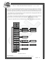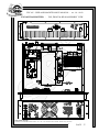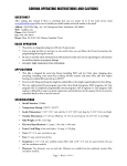
1
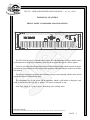
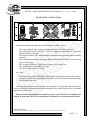
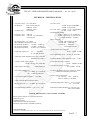
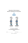
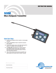
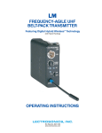
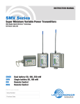
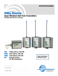
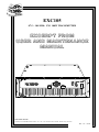
EXC105
87.5 ÷ 108 MHz FM 100W TRANSMITTER
EXCERPT FROM
USER AND MAINTENANCE
MANUAL
SIEL Sistemi elettronici
Via Bari, 26 - 20143 MILANO - ITALY - tel. +39 - 2 - 89 150 150 - fax 81 36 038 - Email: siel @ siel.com
Rev. 1.0 - 01/02
EXC105 - USER AND MAINTENANCE MANUAL - rev.1.0 - 01/02
CONTENTS
1
INTRODUCTION ................................................................................................... 3
2
GENERAL DESCRIPTION ................................................................................... 4
3
TECHNICAL FEATURES ..................................................................................... 5
4
TECHNICAL SPECIFICATIONS ....................................................................... 7
5
INSTALLATION AND USE .................................................................................. 8
5.1 FOREWORD TO INSTALLATION .......................................................... 8
5.2 SYSTEM CONNECTION ............................................................................ 8
5.3 LF CONNECTION AND PRESETS .......................................................... 10
5.4 OPERATION ................................................................................................ 15
6
COMMANDS AND PROGRAMMING ............................................................. 18
6.1 PASSWORD ORGANISATION ................................................................. 18
6.2 FACTORY DEFAULT PASSWORDS ........................................................ 19
6.3 MENU AND COMMANDS DESCRIPTION ........................................... 19
7
SERVICE AND MAINTENANCE ....................................................................... 30
8
GUARANTEE ......................................................................................................... 30
9
SERVICE MANUAL ............................................................................................. 31
9.1 INTERNAL DESCRIPTION ...................................................................... 31
A.1
A.2
DRAWINGS
EXC105, top, front & rear assembly view
EXC105, general electric diagram (E0901)
SEXC25CON, cpu controller and display board (E0838)
SEXC25MB, lf and rf control mainboard (E0837)
SEXC25MOD FM exciter board (E0839)
ASEXC101AMP FM 100W power amplifier (E0514A)
SEXC23COD2 stereo encoder board (E0868)
ASEXC105AL power supply regulator assembly (E0913)
SIEL Sistemi elettronici
Via Bari, 26 - 20143 MILANO - ITALY - tel. +39 - 2 - 89 150 150 - fax 81 36 038 - Email: siel @ siel.com
PAGE 2
EXC105 - USER AND MAINTENANCE MANUAL - rev.1.0 - 01/02
EXC 105
87.5 ÷ 108 MHz FM 100W TRANSMITTER
INTRODUCTION
The EXC105 series transmitters are the result of experience gained by SIEL during years of
producing FM broadcast equipment, transmitters, stl and stereo encoders.
These transmitters were specifically designed to comply with the latest international standards and
the requirements of advanced broadcasters, meeting tighter specifications than usually required, at an
affordable cost.
Great care went into producing a Hi-Fi-quality modulated signal, with low residual noise and
distortion. The RF signal is also free from spurious and harmonic components to a higher degree than
required by CCIR, European, USA and most other national standards.
To obtain this outstanding performance, SIEL strongly recommend to rely on qualified personnel
to install and verify the equipment which makes up the radio station, i.e. the transmitter, the possible
stl and power amplifier, the corresponding antennas, cables and connectors. This will assure to achieve
the best performance and stability in time.
To this aim, SIEL especially recommend that their equipment should not be tampered with by
unskilled personnel and its after-sale service is available to customers for any technical problem.
Before proceeding to installation, please carefully read at least the general installation part of this manual,
to gain confidence with the equipment.
The transmitters are very stable and changes to the internal pre-setting other than frequency and few
other options are not usually required but, if they are, once again they must be done by skilled personnel,
with proper instrumentation and service documentation. Improperly tampering with the settings may
harm the apparatus or jeopardize the guaranteed performance.
THIS EQUIPMENT COMPLIES WITH ALL RELEVANT
EMI/EMC AND SAFETY
REQUIREMENTS, ETSI EN300384, ETS300447 AND EN60215 STANDARDS.
NO INTERNAL ADJUSTMENT OR PRESETTING IS REQUIRED DURING NORMAL
OPERATIONS. THE APPARATUS SHALL BE PROPERLY EARTHED AND BE
OPERATED WITH ALL THE COVERS CLOSED TO PREVENT ELECTRICAL
HAZARDS AND COMPLY WITH EMC STANDARDS.
——— MAINS VOLTAGE MAY KILL ———
SIEL Sistemi elettronici
Via Bari, 26 - 20143 MILANO - ITALY - tel. +39 - 2 - 89 150 150 - fax 81 36 038 - Email: siel @ siel.com
PAGE 3
EXC105 - USER AND MAINTENANCE MANUAL - rev.1.0 - 01/02
GENERAL DESCRIPTION
The EXC105 is a 100W rated, direct-synthesis, FM-modulated transmitter. Being digitally
controlled, it is extensively on field programmable by front panel or remotely in every respect: frequency,
power, channel sensitivity, preemphasis, functioning mode (mono, stereo, external mpx), clock and
date and many other parameters without adjusting or substituting any part. A powerful 3-levels
password management permits a very high degree of security and privacy as may be required in different
situations. The apparatus requires little o no maintenance and its simple modular layout facilitates stage
testing and servicing.
As imposed by various national standards, these transmitters incorporate sophisticated low-pass
audio filters on mono and stereo channels, and a sharp acting modulation limiter, which is usually set
at a peak deviation slightly higher than 75 kHz. Its intervention may nevertheless be avoided, if required,
pre-setting its threshold at a deviation higher than 150 kHz.
Output frequency is phase-locked to a temperature-compensated crystal oscillator, which
ensures superior precision and stability. A very low noise, low distortion VCO produces a
harmonic-free, spurious-free signal. A lock control circuit inhibits the presence of power on the
output until the apparatus is on the right frequency, when turning on.
To lower the noise threshold further, the low-frequency inputs are fitted with balanced input circuitry.
The input level is precisely adjustable over a broad range, by means of a 0.5dB stepwise variable
attenuators. The transmitter has an auxiliary input, specifically designed for RDS and SCA encoders.
A modulation output permits to control other transmitters or STL's with the same internally processed
high-quality mpx signal.
The alphanumeric display permits easy and accurate metering, adjustment and continuous
monitoring of modulation levels, power, operation and internal parameters. All these information may
be externally available on the same RS232 I/O port that may be used to remotely control the transmitter.
In addition to the serial I/O, some signals (RF power, On the air state, Disable line) are available on
a parallel I/O socket for easy interfacing with others analog controllers or supervisory systems.
A top-quality stereo encoder may be factory installed as option and even retrofitted in the field
in a second time, requiring minimum technical skill. The powerful internal software and monitoring
functions recognise its presence and enable its functions.
The RF power amplifier employs a broadband design and has plenty of reserve: the output power
is feedback controlled for increased stability till higher than nominal level. High reflected power is limited
to prevent output stage degradation; direct power is accordingly continuously reduced so as not to
exceed the reflected power safety level. A sturdy telecom-grade high efficiency switch-mode power
supply permits operation in a very wide and noisy mains environment.
The temperature alarm circuitry reduce the output power in case of high internal or ambient
temperature, trying to continue to stay on the air in spite of the adverse conditions.
SIEL Sistemi elettronici
Via Bari, 26 - 20143 MILANO - ITALY - tel. +39 - 2 - 89 150 150 - fax 81 36 038 - Email: siel @ siel.com
PAGE 4
EXC105 - USER AND MAINTENANCE MANUAL - rev.1.0 - 01/02
TECHNICAL FEATURES
FRONT PANEL COMMANDS AND SIGNALLING
The EXC105 front panel is clean and easy to control. The wide alphanumeric display and the control
keyboard permit a simple self-explanatory menu-driven navigation through the various options.
Great care was taken in the design of the software to allow natural feeling with the controls to permit
operation and programming in every respect of the apparatus without needing to extensively read the
user-manual.
The password management, hides some functions and prevents tampering with the most critical
options and data to unauthorised people.
The on/stand-by key do not power off the apparatus, which is still locked on frequency and
ready to transmit as soon the key is pushed or a remote command is sent.
Some leds signal at a glance proper functioning and warning states.
SIEL Sistemi elettronici
Via Bari, 26 - 20143 MILANO - ITALY - tel. +39 - 2 - 89 150 150 - fax 81 36 038 - Email: siel @ siel.com
PAGE 5
EXC105 - USER AND MAINTENANCE MANUAL - rev.1.0 - 01/02
REAR PANEL CONNECTORS
All transmitter inputs and outputs are allocated on the rear panel. They are:
- The audio channels input sockets on balanced female XLR-type connectors
- The wide-band external processed / stereo or composite signal input on a grounded
unbalanced BNC connector
- The frequency limited (20k÷ 100kHz) auxiliary channel input on a grounded, unbalanced BNC
connector
- The lf modulation output for monitoring, RDS external synchronisation or re-broadcasting
purpose, BNC-type
- The inverted wired RS232 DB9 female remote serial control port
- The parallel control port, DB9 male type
- The RF antenna connector, N-type
Note that:
- The hot centre-pin on the "EXTERNAL" BNC input is physically in parallel with the signal +
input (pin 3) on the mono/right channel XLR socket. For this reason both connectors cannot
be used at the same time.
On the left side of the panel it is located the mains supply IEC320-type outlet and an earth screw
for system earthing in addition to the ground pin on mains socket. On the same socket it is located the
mains switch and the fuses.
Please note that the transmitter is usually factory pre-set for 220-240 Vac nominal mains
voltage. If requested, 110-120 Vac range must be internally set on the mains tranformer.
SIEL Sistemi elettronici
Via Bari, 26 - 20143 MILANO - ITALY - tel. +39 - 2 - 89 150 150 - fax 81 36 038 - Email: siel @ siel.com
PAGE 6
EXC105 - USER AND MAINTENANCE MANUAL - rev.1.0 - 01/02
TECHNICAL SPECIFICATIONS
- Frequency range: 87.5÷108 MHz
- Modulation:
FM, 75 kHz peak dev.
180kF3E mono
256kF3E stereo
- Synthesis step:
10/100 kHz
- Frequency error:
- Frequency drift:
-
<200 Hz
<250 Hz over temperature
<100 Hz/year
RF output power: 10 ÷ 100W
Max allowable reflected power: 10W
RF harmonic products:
<-67 dBc, -72 dBc typ.
RF spurious products:
<-85 dBc, -95 dBc typ.
RF output impedance:
50 ohm on N connector
- Audio/mpx input level:
-3.5 ÷ +12.5 dBm
@ ±75 kHz deviation
- S/N ratio, mono:
≥76 dB 86 typ.(30÷20000Hz)
≥75 dB 81 typ.(CCIR)
- S/N ratio, stereo: ≥72 dB 77 typ. (30÷20000Hz)
≥68 dB 72 typ. CCIR
- Modulation distortion:
<0.05% 0.02% typ. @ 75 kHz dev.
<0.2% ≤0.05% typ. @ 150 kHz dev.
(limiter threshold > 150 kHz)
- Stereo crosstalk:
<-50 dB with external encoder
<-60 dB (100 ÷ 5000 Hz)
<-50 dB (30 ÷ 15000 Hz)
with internal encoder
- Audio channel freq. response:
30 Hz ÷ 15 kHz ±0.1dB
- Out of band filter reject.: >50 dB @ F≥19 kHz
- Audio/mpx input impedance:10 k ohm / 600 ohm
bal/unbalanced, select.
- Common mode input rejection:
>50 dB >60 typ. (20 ÷ 15000 Hz)
- Audio input connectors:
female XLR type
- Aux channel input level:
-12.5 ÷ +3.5 dBm @ ±7.5 kHz dev.
-24 ÷ -8 dBm @ ±2 kHz dev.
- Aux channel input impedance:
10 k ohm
- Deviation limiter: adjust. between 0 and > +7 dB
- Composite input freq. response:
10 Hz ÷ 100 kHz ±0.1dB
- Aux input frequency response:
10 ÷ 100 kHz ±0.2 dB
- I/O lines: RF disable, Direct pw, On the air, Alarm
RS232 for monitoring and control
- Mains supply requirements:
115 / 230 Vac ±15% 50/60 Hz
320 VA / 220W @ 100 Wout
- Linear and aux input connectors: BNC
- Mpx output level: 0 ÷ +10 dBm @ ±75 kHz dev.
- Preemphasis time constant: 0 / 50 / 75 µs ±2%
- Operating temperature range: 0 ÷ 35 °C recomm.
-10 ÷ 45 °C max
- Dimensions without handles: 19" 3 un. std. rack
483 x 132.5 x 360mm
CHECK, PROTECTION AND CONTROL SYSTEMS
Block against emission on spurious frequencies
Reflected power
Modulation limiter
High internal or external temperature
Real-time clock and date, with battery back-up
SIEL Sistemi elettronici
Via Bari, 26 - 20143 MILANO - ITALY - tel. +39 - 2 - 89 150 150 - fax 81 36 038 - Email: siel @ siel.com
PAGE 7
EXC105 - USER AND MAINTENANCE MANUAL - rev.1.0 - 01/02
COMMANDS AND PROGRAMMING
The transmitter permits exhaustive control of all transmission parameters and complete programmability
and monitoring facilities through the various software controls via the front panel keyboard and display.
The same functions are remotely addressable with proper software, which is not included as a standard
option other than some simple demo programs.
For a description of remote capability see the proper section on the manual. In this section we will
examine the front panel menu-driven operational capability.
PASSWORD ORGANISATION
The password organisation is set in 3 security levels, each with its own password. A higher level
permits to change the lower levels authorisations and passwords.
The password is composed by 4 alphanumeric characters, including extended capital and lower
case ones and several special symbols. We suggest using a wide range of characters as the security level
raises, to increase the possible combinations. No password is ever shown: it is always masked by
dummy characters as "...." or "****". Nevertheless it may be always changed with the higher level
authorisation. Here is the purpose of each level:
Level 1:Lower security level. It is needed to access to most of the monitoring and control menu
fields, not permitting to alter or programming any operating parameter. It is set to "off" state
as default, permitting to anybody to navigate freely through transmitter's monitoring menu
information. SIEL suggests leaving it in this state if a high privacy level is not needed.
If set to "on" it will show the default menu field #00 (c.r. menu tree), requiring password for
any other information or pre-set. Failure to insert a correct password of any level will impede
any other access to the commands for the time-out length (usually 3 minutes).
No change to the functioning mode is done in case of incorrect password input. No
information is available on the display regarding the transmitter functioning.
Level 2:Service level. This password is needed for any functioning set-up as frequency and power,
sensitivities, clock and date etc. Its use is reserved to service technicians who need wide
access to the transmitter presets and functions.
While the default factory state is "off", SIEL suggests changing the default state and
password immediately at the first power on, to prevent to unauthorised people to tamper
with transmitter commands, if the default word is known or the state is set to "off".
Level 3:Highest security level. It is always "on" by default and reset anyway to "on" after the display
time-out, for security purpose. Its knowledge is deserved only tovery fewpeople and must
be immediately registered after setup and kept in a secure place: there is no way to read
it after you have setup and confirmed on the transmitter.
This password must be immediately changed at the first pre-set of the apparatus: if any
SIEL Sistemi elettronici
Via Bari, 26 - 20143 MILANO - ITALY - tel. +39 - 2 - 89 150 150 - fax 81 36 038 - Email: siel @ siel.com
PAGE 18
EXC105 - USER AND MAINTENANCE MANUAL - rev.1.0 - 01/02
unauthorised people tampers with it or you loose it, there is no way to change it if you do
not know the correct word for security reasons and the apparatus may become unmanageable.
Gaining again access to the apparatus will require factory reprogramming or
changing the internal CPU.
For practically any parameters that may require some setting in the field, the 2nd level
password is enough and may be used for any standard service requirement. The main
purpose of the existence of the 3rd level is a security assurance for the user if he looses
control on the lower password levels.
Only very few critical parameters, like limiter permission or control require this password,
as in some countries this functions are not allowed to be freely chosen.
FACTORY DEFAULT PASSWORDS
These are the factory default password:
Level 1:
XXXX
Level 2:
YYYY
Level 3:
ZZZZ
For what previously said, be sure to change at least the 3rd and possibly the 2nd level as soon as
you receive and turn on the apparatus.
For security purpose the 3rd level password may be factory changed from the default value before
the transmitter is shipped, in consequence of a specific final customer request.
MENU AND COMMANDS DESCRIPTION
The hierarchical tree of the menu is depicted in the following table, with a small number near the left
side of each field for easy reference. In the following pages we will examine each menu field and option.
All of the first column fields require the first level password authorisation to be navigated. Similarly
practically all the second column fields require the second level authorisation, as some in the third
column. The third level is required only by some functions in this last column.
Navigation through the menu fields is quite straightforward and natural, with the direction key. "Up"
and "down" key vertically scroll the fields, while the "left" and "right" key horizzontally scroll the menu.
Moving to the right may be impeded by the password permission, while returning to left is always
possible.
The "enter" key changes from scrolling to programming mode, if allowed in the field. Another push
SIEL Sistemi elettronici
Via Bari, 26 - 20143 MILANO - ITALY - tel. +39 - 2 - 89 150 150 - fax 81 36 038 - Email: siel @ siel.com
PAGE 19
EXC105 - USER AND MAINTENANCE MANUAL - rev.1.0 - 01/02
on the "enter" key will confirm the input data. When in program mode, the up and down keys will change
the character, while the left and right key will move the cursor on the field. Pushing on the "escape" key
will abort the input while repeated escape commands will reset the menu field to the default one (#00).
A local input time-out will automatically escape the command mode resetting input data if this is not
confirmed in 60 seconds after the last variation.
Few minutes of experiments will enable most users to gain confidence with control keys and menu
and to be able to access all main features of the transmitter, without any previous training.
Anyway it is impossible to discover hidden functions without the proper password permission.
X25 S/W
Vers. 1.0
11
ENTER PASSWORD
CODE
00
SIEL - MILANO - ITALY
Vers. 1.0
01
DIR POWER 25W
REF POWER 0.0W
21
02
MPX 75KHz +7.1dB
######### 0 |
22
03
LEFT level
RIGHT level
04
L######## 0 |
R######## 0
|
05
AUX
#########
06
07
AUX
00.0
L
0.0
MAX REFL POWER
AUTOCONTROL
SET MPX GAIN
32
MPX LIMIT LEVEL
AUTOCONTROL
-3.0dB
-4.0dB
-11.0dB
|
25
SET AUX GAIN
R
MPX
0.0
0.0
M= MONO PR= OFF
FM 100.0 MHz
08
VS2
Vs+
Vs28V +12.5V -12.7V
09
T=+25°C
01 JAN 01
17:22
12
31
SET DIR POWER
27
29
SET MODE, PREENF.
& FREQ.
SET DATA & TIME
37
FREQUENCY MODE
39
AUTO POWER DOWN?
23:00-06:00 P=50%
ELAPSED TIME
13
SET PASSWORD
LEV.1
14
EXEC SW RESET?
YES/NO
23
CONF. PASSWORD
****
Hierarchical menu tree
SIEL Sistemi elettronici
Via Bari, 26 - 20143 MILANO - ITALY - tel. +39 - 2 - 89 150 150 - fax 81 36 038 - Email: siel @ siel.com
PAGE 20
EXC105 - USER AND MAINTENANCE MANUAL - rev.1.0 - 01/02
EXC105 TRANSMITTER - TOP, FRONT & REAR ASSEMBLY VIEW
SIEL Sistemi elettronici
Via Bari, 26 - 20143 MILANO - ITALY - tel. +39 - 2 - 89 150 150 - fax 81 36 038 - Email: siel @ siel.com
PAGE 37
EXC105 - USER AND MAINTENANCE MANUAL - rev.1.0 - 01/02
EXC105 TRANSMITTER - TOP, FRONT & REAR ASSEMBLY VIEW
SIEL Sistemi elettronici
Via Bari, 26 - 20143 MILANO - ITALY - tel. +39 - 2 - 89 150 150 - fax 81 36 038 - Email: siel @ siel.com
PAGE 37