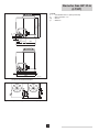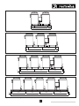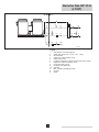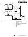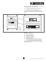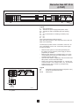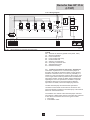
1
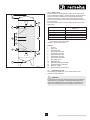
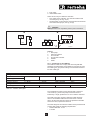
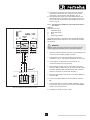
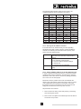
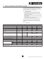
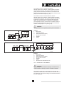
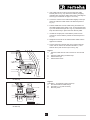
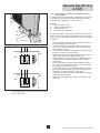
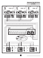
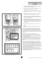
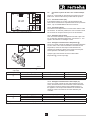
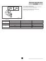
United Kingdom
EN
Gas Absorption Heat pump
Gas HP 35 A (LT/HT)
After Sales
Service guide
renewable technologies
Remeha Gas HP 35 A
(LT/HT)
CONTENTS
1INTRODUCTION
1.1Symbols
1.2 Terms and abbreviations
1.3Liability
1.3.1 Manufacturer's liability
1.3.2 Installer's responsibility
1.3.3 User's responsibility
1.4 Supplementary guidelines
4
4
4
4
4
5
5
5
2 SAFETY INSTRUCTIONS AND RECOMMENDATIONS
2.1 Safety instructions
2.2Recommendations
6
6
6
3 TECHNICAL DESCRIPTION
7
4 THERMAL DESIGN
4.1 Control design
4.2 Hydraulic design
4.2.1 Buffer vessel
4.3 Hydraulic diagrams 8
8
8
9
9
5 GENERAL INSTALLATION
5.1 Installation instructions
5.2 Important points to consider
5.3 Noise and vibrations
5.3.1Noise
5.3.2Vibrations
5.4 Frost protection
5.4.1 Defrosting cycle 5.5 Water treatment
11
11
11
11
11
12
12
12
13
6 INSTALLING A SINGLE HEAT PUMP
6.1 Scope of delivery
6.2 Hydraulic installation
6.2.1 Hydraulic connections
6.2.2 Gas connections
6.2.3 Connecting the condensate drain pipe
6.3 Electrical connections and control - general
6.3.1 Connecting to the main power supply
6.3.2 Controlling the heat pumps via a 0-10 V signal 6.3.3 Controlling the heat pumps via an On/Off signal 6.3.4 Connecting a water circulation pump
6.4 Electrical connections and control - OpenTherm
6.4.1 Introduction to the CAN-bus
6.4.2 Connecting the CAN-bus to the Gas HP heat pump
6.4.3 Connecting the CAN-bus to the CAN-OT interface - two nodes
6.4.4 Connecting the CAN-bus to the CAN-OT interface - several nodes
6.4.5 LED signals for CAN-OT interface
6.4.6 Setting CAN-bus address on the Gas HP heat pump
6.4.7 Connecting the Remeha OpenTherm controller
14
14
14
14
14
14
14
14
14
14
14
14
15
16
17
18
19
19
20
7 INSTALLING SEVERAL HEAT PUMPS ON A SKID 7.1 Scope of delivery
7.2 Technical data
7.3 Hydraulic installation
7.3.1 General installation instructions
7.3.2 Positioning the system 7.3.3 Hydraulic connections
7.3.4 Gas connections
7.3.5 Connecting the condensate drain pipe
7.4 Electrical connections and control - general
7.4.1 Connecting to the main power supply
21
21
21
24
24
24
26
30
30
31
31
2
7.4.2 Connecting the secondary circuit pump
33
7.4.3 Controlling the heat pumps via an On/Off signal
33
7.4.4 Wiring diagram 34
7.5 Electrical connections and control - OpenTherm
34
7.5.1 Introduction to the CAN-bus
35
7.5.2 Connecting the CAN-bus to the GEP connectors - single skid
36
7.5.3 Connecting the CAN-bus to the GEP connectors - several skids
38
7.5.4 Connecting the CAN-bus to the CAN-OT interfaces
39
7.5.5 LED signals for CAN-OT interface
41
7.5.6 Setting CAN-bus address on the heat pump
41
7.5.7 Connecting the Remeha OpenTherm controller
42
7.5.8 Connecting a water circulation pump
42
7.5.9 Controlling the heat pumps via a 0-10 V signal
42
7.6 Connection options for the 0-10 V control PCB (IF-01)
43
7.6.1 Connection status (Nc)
43
7.6.2 Connection (OTm)
43
7.6.3 Analogue input (0-10 V)
43
7.6.4 Analogue control based on temperature (*)43
7.6.5 Analogue control based on heat output (%)
43
7.6.6 Analogue output (0-10 V)
44
8 COMMISSIONING AND LEGISLATION
8.1Introduction
8.2 Regulations and application 8.3 Points to consider regarding the configuration
8.3.1General
8.3.2 Outside configuration
8.3.3 Version and scope of delivery of heat pump
8.4 Points to consider when operating the system
8.5Other
45
45
45
45
45
46
46
46
46
9 INSPECTION AND MAINTENANCE
47
3
Remeha Gas HP 35 A
(LT/HT)
1 INTRODUCTION
This manual is a supplement to the Installation and service
manual for the Remeha Gas HP 35 A gas absorption heat
pump. The manual contains extra information on the design,
installation and maintenance of the heat pump system.
¯ WARNING
For instructions regarding installation and use of the
device, please see the installation, user and maintenance
documentation supplied with the device.
1.1 Symbols
This manual uses various danger levels to draw attention to
the special instructions. We do this to increase the safety of the
user, to prevent problems and to ensure the technical reliability
of the device.
¯ DANGER
Risk of dangerous situations resulting in serious personal
injury.
¯ WARNING
Risk of dangerous situations resulting in minor personal injury.
¯ CAUTION
Risk of material damage.
± Please note, important information
1.2 Terms and abbreviations
•• GEP: switch box for the appliance (marked with MAIN
where necessary).
•• SWW: domestic hot water
•• Skid: heating unit consisting of one general switch box
(GEP) and two to five individual gas absorption heat pumps
that are connected to one another beforehand for gas,
central heating and electricity and linked to one another by
supporting beams.
1.3
Liability
1.3.1 Manufacturer's liability
Our products are manufactured in accordance with the various
guidelines that apply and are therefore supplied with the CE
symbol and all required documents.
Due to our permanent focus on the quality of our products, we
are constantly looking for ways to improve them. We therefore
retain the right to change the specifications mentioned in this
document.
The manufacturer cannot be held liable in the following cases:
•• Failure to observe the user instructions for the appliance.
•• Overdue or inadequate maintenance of the appliance.
•• Failure to observe the installation instructions for the
appliance.
4
The manufacturer will perform the initial commissioning of the
heat pump system.
1.3.2 Installer's responsibility
The installer is responsible for the installation and the initial
commissioning of the appliance. The installer must observe the
following instructions:
•• Read and observe the instructions for the appliance found
in the accompanying manuals.
•• Install the device in accordance with current legislation and
standards.
•• Perform all necessary checks.
•• Explain the installation to the user.
•• If maintenance is required, alert the user to the inspection
and maintenance obligations relating to the appliance.
•• Hand over all manuals to the user.
1.3.3 User's responsibility
In order to guarantee optimum functioning of the installation,
you must observe the following instructions:
•• Read and observe the instructions for the appliance found
in the accompanying manuals.
•• Request the assistance of a qualified installer for the
installation.
•• Ask Remeha to perform initial commissioning of the
appliance.
•• Ask the installer to explain the installation.
•• Ensure that the necessary checks and maintenance work
are carried out.
•• Keep the manuals in good condition and near to the
appliance.
This appliance must not be used by people (and children)
with a physical, sensory or mental disability, or by people with
a lack of technical experience, unless they are supervised
by someone who can assure their safety, or they have been
instructed in the correct use of the appliance. Do not allow
children to play with the appliance.
1.4 Supplementary guidelines
In addition to the legal requirements and guidelines, the
supplementary guidelines in this manual must also be followed.
Supplements or subsequent regulations and guidelines that are
valid at the time of installation shall apply to all regulations and
guidelines specified in this manual.
5
Remeha Gas HP 35 A
(LT/HT)
2 SAFETY INSTRUCTIONS AND RECOMMENDATIONS
2.1
Safety instructions
¯ DANGER
If you smell gas:
1. Do not use naked flames, do not smoke and do not operate
electrical contacts or switches (doorbell, lighting, motor, lift
etc).
2. Shut off the gas supply.
3. Trace possible leaks and seal them off immediately.
4. If the leak is upstream of the gas meter, notify the gas
company.
¯ DANGER
If you smell flue gases:
1. Turn off the device.
2. Trace possible leaks and seal them off immediately.
¯ DANGER
The heat pump has a closed cooling circuit with an ammonia/
water mixture under overpressure:
1. Avoid contact with skin and do not inhale or swallow the
ammonia mixture.
2. Do not carry out any work on the closed cooling circuit or
on the valves.
¯ DANGER
If you smell ammonia:
1. Turn off the device.
2. Keep your distance and avoid inhaling ammonia fumes.
3. Do not carry out any work on the closed cooling circuit
yourself, but leave this to a qualified installer.
2.2
Recommendations
¯ WARNING
•• Installation and maintenance of the appliance must be
carried out by a qualified installer in accordance with local
and national regulations.
•• When performing work on the appliance, always disconnect
it from the power supply and close the main gas valve.
•• Check the entire system for leaks after maintenance and
servicing work.
Casing panels
Casing panels may only be removed for maintenance and
servicing purposes. Refit all panels when maintenance work
and servicing are complete.
6
3 TECHNICAL DESCRIPTION
The technical data for the heat pump can be found in the
Installation and service manual for the heat pump.
7
Remeha Gas HP 35 A
(LT/HT)
4 THERMAL DESIGN
Gas absorption heat pumps are very efficient heating
appliances, but it is essential that they are integrated correctly
in the heating system in order to obtain maximum output. The
thermal characteristics of the system need to be designed
correctly in order to achieve maximum efficiency of the heat
pumps.
4.1 Control design
•• A continuous on/off cycle (hunting) has a significant
adverse impact on total seasonal efficiency. If the system
has a low thermal capacity on the user side, adding a buffer
vessel will considerably increase total seasonal efficiency.
•• The efficiency of the heat pumps is increased when the
outgoing water temperature is decreased.
•• The system must be designed so that the return
temperature is kept as low as possible, for example by
using modulating system pumps (the heat pump switches
off if the maximum return temperature is exceeded).
4.2 Hydraulic design
•• The choice between the HT and LT versions of the heat
pump depends on the type and design of the distribution
system (underfloor heating, ventilation units, radiators etc).
The HT version has a maximum return temperature of 55°C
(65°C flow), while the LT version has a maximum of 45°C
(55°C flow). Only the LT version is suitable for prolonged
operation at return temperatures below 25°C.
•• When the design return temperature of the system is
lower than 55°C, back-up boilers are not needed for low
outside temperatures. The output ratio between the heat
pumps and the extra boilers can be determined based on
the limiting investment on the one hand and the average
efficiencies on the other.
•• When the design return temperature of the system is higher
than 55°C, back-up boilers are needed for low outside
temperatures. The output of these boilers (excluding the
heat pump output) must be sufficient for the system's heat
demand at the design temperature.
•• The system's design flow temperature can be selected
above the maximum temperature of the heat pump when
the extra boilers are hydraulically connected to the heat
pumps in series (see also Fig. 02 and Fig. 03).
•• The gas absorption heat pump is not the most suitable
method of producing domestic hot water. The heat pump
can be used, however, to pre-heat domestic hot water
where a more complex and more expensive hydraulic
design is acceptable.
•• The outer section of the system can be filled with a glycol
mixture to protect the heat exchanger from freezing.
Unfortunately, the temperature difference across the heat
exchanger will lower the efficiency of the heat pump.
¯ CAUTION
It is important for both the central heating boilers and the heat
pumps that the configuration of the heat transfer element is
part of the hydraulic design, since efficiency increases if the
system is set correctly for both the hydraulics and controls.
8
4.2.1 Buffer vessel
A buffer vessel is not specifically required. If the system does
not have sufficient capacity, a buffer vessel can be built into the
system. The buffer vessel acts as a thermal energy battery,
reducing the number of starts for the heat pumps. Too many
starts in a short period of time reduce the average efficiency of
the heat pumps.
The volume of the buffer vessel (in litres) can be found in the
table below.
1
2
12
11
3
Number of Gas HP units
1
2
3
4
5
4
8
5
13
6
* Effective volume = volume between flow and return
connections on the buffer vessel
Table 01 Buffer vessel volume
7
9
Legend
1
Air vent
2
Lifting eye
3
Heat pump flow
4
Temperature recorder
5
Temperature recorder
6
Temperature recorder
7
Temperature recorder
8
Temperature recorders
9
Heat pump return
10 Draining outlet
11 Separation plate (perforated)
12 Central heating system flow
13 Effective volume
14 Central heating system return
11
14
10
T003992-A
Fig. 01
Effective volume* of buffer
vessel in l
300
500
800
1000
1000
Schematic drawing of the buffer vessel
4.3 Hydraulic diagrams
The following examples only give a broad outline of the
principle of heat production.
¯ CAUTION
It is important for both the central heating boilers and the heat
pumps that the configuration of the heat transfer element is
part of the hydraulic design, since efficiency increases if the
system is set correctly for both the hydraulics and controls.
9
Remeha Gas HP 35 A
(LT/HT)
T004284-A
Fig. 02
Hydraulic diagram with Quinta Pro boilers
T004285-B
Fig. 03
Hydraulic diagram with Gas 310 boilers
10
5 GENERAL INSTALLATION
5.1
Installation instructions
¯ WARNING
The appliance must be installed by a qualified installer in
accordance with local and national regulations.
5.2 Important points to consider
•• The temperature curve for the heat production section must
be within the range of the heat pumps (over a long period).
•• The buffer vessel must not be brought up to temperature
regularly by groups heated to high temperatures where the
temperature curve greatly exceeds the temperature curve
for the heat pumps, such as a boiler group. This means that
these groups must not be present or must be disconnected.
•• The heat pumps must be supported on the main supporting
structure. It is advisable to consult a structural engineer
about this. The structural engineer can also advise on
how to prevent contact noise to the homes involved. To
ensure there is sufficient rigidity, both the supporting beams
and stands under the frame must be at least HEB 160.
The profile can be heavier if this is indicated by the load
capacity calculation. This depends on the model.
•• The heat pumps must be connected with flexible
connections. This applies to both the gas pipe and the
central heating pipes.
•• The heat pumps can be controlled on and off or modulated
with a 0-10 signal (option). OpenTherm control is possible
under certain conditions. Contact our Sales Support
department about this.
•• If filler other than a glycol mixture is used, the installer
himself must provide (better) insulation and an electric frost
protection cable. This also includes the pipe work supplied
with the skid.
•• The pipe work on the accompanying skid has limited
insulation; it is up to the installer to provide better insulation.
•• Evaluation of the complete hydraulic system and
corresponding control engineering should be part of the
inventory. In order to achieve the desired savings and
efficiencies, the system must be configured correctly for
both the hydraulics and controls.
•• Proper monitoring must to be carried out to monitor
the above point. This includes regular evaluation of the
temperature curve and release of the heat-producing
components (heat pumps and boilers). A low supply water
temperature has a positive effect on the operating time
of the heat pump. A low return water temperature has the
same effect and increases efficiency.
5.3
Noise and vibrations
5.3.1 Noise
Noise production of Remeha Gas HP heat pumps
Principles relating to the numbers in Table 02:
•• This refers to a point source of sound, placed on a
reflective surface, as considered from the front.
•• The amount of nuisance for the surrounding area is
also determined by the installation site. This means the
distance and any vertical outer walls in the vicinity will be of
influence.
11
Remeha Gas HP 35 A
(LT/HT)
Distance
Noise capacity
Noise pressure
Gas HP 35 A
73 dB(A)
5m
6m
7m
8m
9m
10 m
11 m
12 m
13 m
14 m
15 m
51 dB(A)
49 dB(A)
48 dB(A)
47 dB(A)
46 dB(A)
45 dB(A)
44 dB(A)
43 dB(A)
43 dB(A)
42 dB(A)
41 dB(A)
Table 02 Noise pollution related to the distance from the heat
pump (1 unit)
Positioning the heat pumps
Preferably install the heat pump on the roof and maintain the
following distances, if possible:
•• At least 4 m from the roof edge to prevent downward
radiation.
•• At least 1.5 m away from any rising outer wall to avoid
amplification of the noise through reflection.
A noise specialist can determine whether the noise pressure
complies with the norms for factors such as the outer walls of
adjacent homes or at the edges of the property line. Additional
noise reduction measures can be taken, if necessary, such as
the installation of noise barriers.
5.3.2 Vibrations
•• The heat pumps must be supported on the main supporting
structure. Ask a structural engineer for advice. He will also
be able to give advice on how to prevent structure-borne
noise being carried to any living areas.
•• Vibration dampers must be fitted between the heat
pumps and the support construction. Standard dampers
are available as an option. Any customised work must
be carried out in consultation with a (noise) expert. The
underlying structure must be sufficiently rigid.
•• The heat pumps must be connected with flexible antivibration connections. This applies to both the gas and
central heating pipes.
5.4 Frost protection
•• Every heat pump has an antifreeze function that can be
activated; see the Installation and service manual for the
heat pump.
•• The extra frost protection measures for a heat pump
system on a skid are explained in section 7.3.3.
•• The use of glycol is dealt with in detail in chapter 4.5 of the
Installation and service manual .
5.4.1 Defrosting cycle
If the heat pump is operating with outside temperatures at
around freezing point or below, the water vapour from the
intake air can freeze on the evaporator fins.
If the automatic antifreeze function is activated, the heat
pump will continue to supply heat to the system and start
12
up a defrosting cycle. This means that the evaporation and
condensation process does not need to be reversed.
During the defrosting cycle, some of the ammonia flow is
fed from the generator (with a temperature of approx. 80°C)
directly to the evaporator, quickly getting rid of ice on the
evaporator. In the meantime, the main ammonia flow continues
to supply heat to the central heating water.
Experience has shown that no more than 50 defrosting
cycles are needed during a normal winter. A cycle only lasts
an average of 3 minutes thanks to the high condensation
temperature of the ammonia flow. As a result, the defrosting
cycle has no measurable effect on the efficiency of the
Remeha heat pump.
5.5 Water treatment
See the Installation and service manual for the heat pump.
13
Remeha Gas HP 35 A
(LT/HT)
6 INSTALLING A SINGLE HEAT PUMP
The installation of the heat pump is described in the
accompanying Installation and service manual. This chapter
provides additional information about possible connections.
6.1 Scope of delivery
See the Installation and service manual for the heat pump.
6.2
Hydraulic installation
6.2.1 Hydraulic connections
See the Installation and service manual for the heat pump.
6.2.2 Gas connections
See the Installation and service manual for the heat pump.
6.2.3 Connecting the condensate drain pipe
See the Installation and service manual for the heat pump.
6.3
Electrical connections and control - general
6.3.1 Connecting to the main power supply
See chapter 5 of the Installation and service manual for the
heat pump.
A
6.3.2 Controlling the heat pumps via a 0-10 V signal
The heat pumps can be controlled via a 0-10 V signal, which
allows the pumps to be modulated between 50 and 100%
output. Each unit is connected separately to a 0-10 V signal.
The 0-10 V control is an expansion of the OpenTherm control.
An OT-0-10V interface must be connected to each CAN-OT
interface. This OT-0-10V interface is available as an accessory
and must be built into a switch box (to be supplied by a
third party). See section 7.5.9 for an explanation of how the
interface works.
B
1234
Off On
Status
Nc C No
0-10 0-10
OTm 0 +
0 +
(A)
On/off
OT
CAN
H L 0 S
Mains
N L
6.3.3 Controlling the heat pumps via an On/Off signal
The heat pumps can be controlled via one On/Off signal per
unit. See the Installation and service manual for the heat pump
for the correct connections
6.3.4 Connecting a water circulation pump
Each heat pump unit can control its own circulation pump. See
the Installation and service manual for the heat pump for the
connections.
If a Rematic MC controller is used in a system with several
heat pumps, a secondary circulation pump (230 V, max. 400
VA) can be controlled on/off.
T003998-B
Fig. 04
OT-0-10V interface (A) and CAN-OT interface (B)
without cover plate
6.4 Electrical connections and control - OpenTherm
This section describes the connection of one or more heat
pumps on a CAN-OT interface. For specific information about
how to use and program a Remeha OpenTherm controller, see
the accompanying manuals.
The Remeha Gas HP heat pump and the Remeha OpenTherm
controllers communicate via the CAN-OT connection. Each
heat pump requires one CAN-OT interface that needs to be
built into a switch box supplied by a third party.
The CAN-bus is a network of Gas HP heat pumps and CANOT interfaces, called nodes, that are connected via a protected
3-wire cable. The network can have two types of nodes:
14
1. End nodes
2. Intermediate nodes
There are two ways to create the CAN-bus:
•• Two nodes on the CAN-bus, one CAN-OT interface and
one heat pump, see Fig. 05 (A).
•• Several nodes on the CAN-bus, several CAN-OT interfaces
and several heat pumps, see Fig. 05 (B)
¯ CAUTION
The OpenTherm bus only allows point-to-point connections.
A
B
3
4
2
CAN
CAN
CAN
OT
OT
OT
2
2
2
OT
1
1
1
1
5
6
T004289-B
Fig. 05
CAN-bus with two nodes (A) and several nodes (B)
Legend
1
Heat pump
2
CAN-OT interface
3
OT controller
4
OT cascade controller
5Outside
6Inside
6.4.1 Introduction to the CAN-bus
The CAN-bus cable must comply with the Honeywell SDS
standard. The table below shows details for a number of CANbus cable types, grouped according to the maximum distance
for each cable type.
CABLE NAME
SIGNAL/COLOUR*
Honeywell SDS 1620 standard
BELDEN 3086A
H = BLACK
TURCK type 530
DevideNet Mid Cable
TURCK type 5711
H = BLUE
Honeywell SDS 2022 standard
TURCK type 531
H = BLUE
MAX. LENGTH
L = WHITE
GND = BROWN
450 m
L = WHITE
GND = BROWN
450 m
L = WHITE
GND = BROWN
200 m
* In all cases: do not use the fourth wire.
Table 03 CAN-bus cable types
For total distances ≤ 200 m and networks with a maximum
of six nodes (e.g. three heat pumps and three CAN-OT
interfaces), a single, protected 3 x 0.75 mm cable is sufficient.
The CAN-connection requires a CAN-bus cable with three
wires. If the available cable has more than three coloured
wires, use the wires with the colours as specified in the table
and cut the other, superfluous wires off.
The entire length of the CAN-bus cable must be protected with
a casing that meets the following requirements:
•• Nominal diameter 17 mm
•• T-section
15
Remeha Gas HP 35 A
(LT/HT)
•• Operating temperature 105°C
•• Flame retardant
•• Resistant to acid, oil, solvents and fuels
The TEAFLEX PAS T 17S casing meets these requirements.
6.4.2 Connecting the CAN-bus to the Gas HP heat pump
The CAN-bus cable must be connected to the special
connector that is located on the internal control unit for the heat
pump.
Legend
A
Insulation tape to protect the controller
B
CAN-bus cable casing (pre-wired from the penultimate
heat pump)
C
Bracket to secure the CAN-bus cable
D
Connector to connect the CAN-bus cables (see Fig. 07
and Fig. 08)
E
Wires (3) for the CAN-bus cable
F
Bracket to secure the CAN-bus cable to the next heat
pump (intermediate node)
E
A B
F
C
D
T003995-A
Fig. 06
CAN-bus cable connection (end node) on the
printed circuit board for the Gas HP heat pump
¯ WARNING
Make sure the heat pump has been disconnected from the
power supply before starting work on the electrical panel.
1. Cut off a piece of cable that is long enough for the
connection without any loops forming.
2. Remove approximately 70-80 mm of the cable casing
and the wires within it. Make sure you do not damage the
shield.
3. If the cable used is too thin to be secured in the cable
bracket (see C in Fig. 06), thicken the cable by wrapping
insulation tape around the cable casing next to the stripped
section (up to a diameter of approx. 12-13 mm).
4. Pull the shield back over the cable casing and use
insulation tape to fasten the end of the shield that has been
pulled back (see Fig. 06 (A)).
5. If the heat pump is an end node in the network, connect the
three coloured wires to the orange connector as shown for
D in Fig. 06. Connect the correct colours to the L, H and
GND connections as indicated in Table 03 and Fig. 07.
6. If the heat pump is an intermediate node, repeat steps 2
to 5 for a different piece of cable so that two cables are
available with the cable casing removed at one end. Always
plait the two wires with the same colour together and then
connect them to the orange connector as shown for D in
Fig. 06 and in Fig. 08.
7. Use the cable bracket to secure the CAN-bus cable(s) to
the top part of the inside of the electrical panel in such a
way that the cable casing that is folded back is in close
contact with the metal bracket (see Fig. 06 C and F). The
bracket must keep the cables in place firmly when the
cables are pulled.
The jumper settings on the control unit depend on the node
type:
16
A. If the Gas HP heat pump is an end node in the network
(three wires connected to the orange connector on the
control unit), set the jumper as illustrated in Fig. 07.
B. If the Gas HP heat pump is an intermediate node in the
network (six wires connected to the orange connector on
the control unit), set the jumper as illustrated for devices 1
and 2 in Fig. 08.
6.4.3 Connecting the CAN-bus to the CAN-OT interface two nodes
Legend
GNDCommon data
L
LOW data signal
H
HIGH data signal
0Zero
S
SHIELD (protection)
(A)
CAN / OT
X2
On/off
OT
OT
Jumper
CN3
X1
The CAN-bus cable is connected to the special yellow/green
HL0S connector that is fitted in the X2 connector of the CANOT interface.
Mains
CAN
H L 0 S
H L 0 S
¯ WARNING
Make sure the heat pump has been disconnected from the
power supply before starting work on the electrical panel.
N L
N L
1. Open the CAN-OT interface from above by pressing the top
of the cover and carefully pulling it forward.
2. The jumpers on the CAN-OT interface must be set as
indicated in Fig. 07. The CAN/OT interface is an end node.
3. Cut off a piece of cable that is long enough for the
connection without any loops forming.
S61
H
P8
5. Disconnect the cable connector from connection HL0S on
connector X2.
Jumper J1
GND L
4. Remove approximately 20 mm of the cable casing and
the wires within it. Make sure you do not cut into the cable
protection (plaited metal or aluminium foil and, if present,
the bare connection in contact with the plait).
6. Connect the cable's shield to connection S on connector
X2.
7. Connect the cable to connector X2 as indicated in Fig. 07.
Pay attention to the marks on the connector where GND
needs to be connected to O.
T003993-B
Fig. 07
Connections on the CAN-OpenTherm interface and
Gas HP printed circuit board (two nodes)
8. Refasten the cable connector on X2.
17
Remeha Gas HP 35 A
(LT/HT)
6.4.4 Connecting the CAN-bus to the CAN-OT interface several nodes
2
(A)
1
(A)
CAN / OT
X2
On/off
OT
OT
CAN / OT
X2
X1
Mains
CAN
H L 0 S
H L 0 S
On/off
N L
N L
OT
OT
GND L H
S61
2
X2
Mains
H L 0 S
H L 0 S
GND L
P8
CAN / OT
X1
CAN
On/off
N L
N L
OT
OT
H
S61
0
(A)
X1
H L 0 S
H L 0 S
GND L
P8
1
Mains
CAN
S61
N L
N L
H
P8
0
T003991-C
Fig. 08
Connections on the CAN-OpenTherm interface and Gas HP printed circuit board (several nodes)
Legend
S61
CAN/OT
J1
CN3
A
P8
CAN
Heat pump printed circuit board
CAN/OT interface
CAN-bus jumper
CAN-bus jumper
Addressing jumper interface
CAN-connector
CAN-connector
CAN-OT interfaces 1 + 2 and heat pumps 1 + 2 are
intermediate nodes
CAN-OT interface 0 and heat pump 0 are end nodes
18
The following table indicates which jumpers need to be
configured together with the address in the device.
Unit
address
0
1
2
3
4
5
6
7
8
9
10
11
12
13
14
15
Jumper 1
position
OFF
OFF
OFF
OFF
OFF
OFF
OFF
OFF
ON
ON
ON
ON
ON
ON
ON
ON
Jumper 2
position
OFF
OFF
OFF
OFF
ON
ON
ON
ON
OFF
OFF
OFF
OFF
ON
ON
ON
ON
Jumper 3
position
OFF
OFF
ON
ON
OFF
OFF
ON
ON
OFF
OFF
ON
ON
OFF
OFF
ON
ON
Jumper 4
position
OFF
ON
OFF
ON
OFF
ON
OFF
ON
OFF
ON
OFF
ON
OFF
ON
OFF
ON
Table 04 Address table
6.4.5 LED signals for CAN-OT interface
If several faults occur simultaneously, the LED signalling
will display each fault in order of priority, until the problem is
resolved. The following list shows the order of priority. LED
status 0 has the highest priority.
LED on
LED flashes
LED off
No errors
OpenTherm and CAN-bus communication
working
2x: No OpenTherm communication
3x: No CAN-bus communication
4x: Incorrect CAN-bus address settings
5x: Internal error
6x: CAN device is not supported
No voltage
Faulty
Table 05 LED signals for CAN-OT interface
6.4.6 Setting CAN-bus address on the Gas HP heat pump
In order to operate several heat pumps in a CAN-bus network
combined with CAN-OT interfaces, each heat pump must be
allocated a clear code. This can be done by setting parameter
40 in menu 5 for the heat pumps.
Parameter 40 is the printed circuit code and identifies the
device in the CAN network. Each heat pump is given a unique
code, independent of its position in the system. The value
that needs to be set for parameter 40 is the numerical code
assigned to the device and can vary from 0 to 478.
Set parameter 40 as follows:
1. Remove the front casing of the heat pump by unscrewing
and removing the screws.
2. Remove the cover plate of the electrical panel to be able to
access the set-up button.
19
Remeha Gas HP 35 A
(LT/HT)
3. Insert the supplied key in the set-up button to access the
control menus and the parameters.
4. Press the button once to display the available menus; the
display shows the first menu as "0" (menu 0).
5. Rotate the button clockwise to display the other menus; the
display then shows "1", "2", "3", "4", "5", "6", "7", "8" and
"E".
6. Rotate the button to menu 5 to set the CAN-bus address.
Press the button to make a selection or to confirm.
7. Use access code 2222 to access menu 5. Rotate the
button to 2 and press to confirm. Repeat this until you have
entered the full access code.
8. Rotate the button to parameter 40 and press to confirm.
Now enter the CAN-bus address for the heat pump. Rotate
the button to the number to be entered and press to
confirm. Repeat this action until the complete address has
been entered.
9. Go to menu E and press the button to leave the control
menus.
10.Replace the cover plate for the switch box and the front
casing.
6.4.7 Connecting the Remeha OpenTherm controller
Use two-wire cables to connect each CAN-OT interface to
the OpenTherm (cascade) controller. A simple 2 x 0.5 mm
unprotected cable can be used. OpenTherm is not susceptible
to polarity, so the wires can be swapped.
20
7 INSTALLING SEVERAL HEAT PUMPS ON A SKID
This chapter describes the installation of a group of heat
pumps on a skid. See the Installation and service manual for
the Gas HP heat pump for the commissioning, gas changes,
service and maintenance of the heat pumps.
7.1 Scope of delivery
•• Frame consisting of thermally galvanised steel beams.
•• Stainless steel main pipes and distribution manifolds,
insulated by an insulation cover with an aluminium finish.
•• Galvanised steel gas pipes
•• Flexible couplings for connecting the individual heat pumps
to the manifolds
•• Independent modulating circulation pump (per heat pump)
•• External switch box with automatic fuses
•• Central condensate drain with internal trace heating
See the Installation and service manual for the technical
specifications, control and safety components of the heat
pumps.
7.2
Installation data
Unit
Number of Gas HP pumps
Output (A7/W50)
Load (Hi)
Gas consumption (G25)
Nominal rate of flow (∆T 10 K)
Residual lift
(∆T 10 K)
Water content
Supply voltage (voltage, type - frequency)
n.
kW
kW
m3/h
m3/h
Max. electricity consumption
Electrical protection index
Gas connection ∅ (2)
Water connection (flow/return) ∅ (2)
Condensate drain ∅ (2)
Noise level (max.) at 10 m (3)
Dimensions
Width
Depth
Height
Weight
(2)
For details, see Fig. 17 and Fig. 18
(3)
Free field, frontal
kPa
l
W
Technical data
Data per skid
2
70
51.4
6.32
6
3
105
77.1
9.48
9
15.5
230 V - 50 Hz
or
400 V 3 + N 50 Hz
2640
23.7
4
140
102.8
12.64
12
5
175
128.5
15.80
15
32.2
41.5
20
400 V 3 + N - 50 Hz
3960
5280
6600
53
4940
54
6490
1920
2395
IP X5D
1 ½” F
2” M
1” F
“
“
“
dB(A)
mm
mm
mm
kg
50
2320
52
3610
1245
1650
970
Table 06 Technical data for Remeha Gas HP 35 A units on a skid
21
1425
Remeha Gas HP 35 A
(LT/HT)
1650
132
92
1400
Legend:
C
= Condensate drain 1" (clamp-mounted)
G = Gas connection 1 ½"
Up = Flow 2"
Ip = Return 2"
133
100
255
378
G Up
Ip
245
1245
1045
622
100
1245
T004109-A
Fig. 09
Connection side of the configuration, with mounting
points for the vibration dampers
Fig. 10
Top of the configuration with two heat pumps
T004110-A
22
380
1554
380
2314
T004286-A
Fig. 11
Front of the configuration with two heat pumps
251
1554
1554
251
3610
Fig. 12
T004106-A
Front of the configuration with three heat pumps
137
1554
1554
1554
137
4936
Fig. 13
137
T004107-A
Front of the configuration with four heat pumps
1554
1554
1554
1554
137
6490
T004108-A
Fig. 14
Front of the configuration with five heat pumps
23
Remeha Gas HP 35 A
(LT/HT)
7.3
Hydraulic installation
7.3.1 General installation instructions
•• Thoroughly clean the inside of all pipes and all parts to be
used in the system before starting the installation.
•• Check whether the gas supply complies with the
specifications of the system's manufacturer. See the
accompanying manuals.
•• The system must be installed on the outside of the
building, in an area with natural air circulation and sufficient
protection from the weather.
•• The system can be installed on the ground floor or on a
terrace or roof, if the terrace or roof is suitable for the size
and weight of the system.
¯ WARNING
The system must not be installed in a closed room.
¯ CAUTION
The system must be installed in an area that is always
accessible.
•• The fan discharge opening at the top of the appliance must
not be obstructed or covered by overhanging constructions
(protruding roofs, roof edges, balconies, ledges or trees).
•• Do not place the system in the immediate vicinity of gas
outlets, chimneys or similar objects, in order to prevent hot
or polluted air from being sucked in by the fan.
•• If the system has to be installed near other buildings, make
sure there is no risk of water leaking onto it from dripping
gutters etc.
•• A gas cock and flexible coupling are needed to connect the
gas supply.
•• Use flexible connections (anti-vibration connecting pieces)
between the heat pump system and the hydraulic and gas
supply pipes.
•• See the Installation and service manual for the heat pump
for specific instructions regarding the installation of the heat
pump.
7.3.2 Positioning the system
Lifting instructions
The heat pump system must remain in its original packaging
during positioning.
¯ CAUTION
Only remove the factory packaging once the system is
definitely in place.
If the system needs to be lifted, secure two hoisting belts or
cables to the openings provided at the bottom of the system.
Use spacer bars to prevent the cables from damaging the
panels during lifting when the system is moved. (See Fig. 15).
24
¯ WARNING
•• The crane and all required accessories (belts, cables, bars
etc.) must be strong enough for the load to be lifted.
•• The manufacturer cannot be held liable for any damage
that occurs during the positioning and installation of the
heat pump system.
See section 7.2 for the system's weight
A
B
T004102-A
Fig. 15
Moving the system
Legend
A
Front view
B
Side view
Surface
¯ CAUTION
Place the system level on a flat, horizontal surface made
from fire-resistant material that is suitable for supporting the
system's weight.
Installation on the ground floor
If no horizontal surface is available, a flat concrete base must
be created that is at least 100-150 mm larger on all sides than
the dimensions of the bottom of the heat pump system. See
section 7.2 for the system's dimensions.
Installation on a terrace or roof
The structure of the building must be able to support the weight
of the heat pump system and the supporting base. See section
7.2 for the system's weight.
Do not position the heat pump system directly above rooms
where silence is required, such as bedrooms, meeting rooms
etc.
Support and levelling
The heat pump system must be levelled using a spirit level
on the top part of the system. If necessary, the system can be
levelled using metal shim plates. Take the system's support
legs into account when inserting the shim plates. The skid
25
Remeha Gas HP 35 A
(LT/HT)
must be secured (separated acoustically) to the lower frame to
provide sufficient resistance to the weather.
¯ CAUTION
Do not use wooden shims as these are quickly affected by
moisture.
Free space
Position the heat pump system so that there is sufficient
distance from combustible surfaces, walls or other appliances.
Maintain the minimum distance as indicated in Fig. 16.
800
600
A minimum amount of free space is needed in order to perform
maintenance on the system and to guarantee sufficient air
supply for the fans in the heat pumps. Create a gangway
around the system, if necessary.
450
450
T004103-A
Fig. 16
Minimum amount of free space around the heat pump system
7.3.3 Hydraulic connections
General guidelines
•• Use pipes made from stainless steel, steel, copper or
cross-linked polyethylene that is suitable for this purpose.
All water pipes and connections must be sufficiently
insulated, in accordance with current standards, in order to
prevent loss of heat and the development of condensation.
¯ WARNING
Do not use galvanised pipes or connections when using a
glycol mixture as the antifreeze agent. This is because of the
risk of corrosion.
•• Use anti-vibration connecting pieces to prevent vibrations
when rigid pipes are used for the system's water supply
and discharge.
26
•• See the Installation and service manual for the heat pump
for the required water quality.
Frost protection
To limit the risk of the system freezing, the heat pumps are
equipped with an antifreeze function. When the antifreeze
function is activated, the external water circulation pump and, if
necessary, the correct burner will be started.
See the Installation and service manual for the heat pump on
how to switch on the antifreeze function.
It is important to ensure there is a continuous supply of gas
and electricity to the system during the entire winter period.
If a continuous supply cannot be guaranteed, the following
measures must be taken:
1. Fit all the outdoor pipe work (including the part delivered
with the skid) with a suitable frost protection cable system
and improved insulation. The frost protection cable system
can, preferably, be fitted with its own separate power
supply.
2. Use monoethylene glycol as an antifreeze. See Installation
and service manual for the required glycol quality. When
using antifreeze, you will need to install an extra plate heat
exchanger between the outer and inner parts of the system.
Even using an oversized heat exchanger may result in
extra loss of efficiency due to the extra temperature step
in the heat exchange. The dimensions of the pipes and
the pump must be adequate for a nominal water flow that
is sufficient for the system to function correctly. Take into
account the internal pressure drop in the system.
¯ CAUTION
•• A glycol and water mixture has a different viscosity and
heat capacity from water.
•• The glycol and water mixture needs to be checked and
replaced periodically.
Fig. 17 and Fig. 18 show the hydraulic fittings needed to
connect one or more heat pumps.
27
Remeha Gas HP 35 A
(LT/HT)
B
C
A
5
1
6
3
3
4
1
1
7
2
9
3
3
3 8
3
Gas
Gaz
T004104-C
Fig. 17
Hydraulic connection of one skid
Legend
1
Anti-vibration connecting pieces
2
Water filter (mesh min. 0.7 mm - max. 1 mm)
3
Shut-off valve
4
Expansion vessel primary circuit
5
Safety valve 3 bar
6
Hydraulic separation or buffer vessel (with vent and tap)
7
Expansion vessel secondary circuit
8
Pump secondary circuit
9
Controller (via interfaces)
10 Gas filter
A
Max. useable residual lift 20 kPa
BOutside
CInside
28
B
C
A
5
1
1
4
2
9
1
1
1
3
5
1
4
3
6
Gas
Gaz
3
2
9
6
3
3
3
6
3
7
Gas
Gaz
3 8
3
A
T004301-C
Fig. 18
Hydraulic connection of two skids
Legend
1
Anti-vibration connecting pieces
2
Water filter (mesh min. 0,7 mm - max. 1 mm)
3
Shut-off valve
4
Expansion vessel primary circuit
5
Safety valve 3 bar
6
Hydraulic separation or buffer vessel (with vent and tap)
7
Expansion vessel secondary circuit
8
Pump secondary circuit
9
Controller (via interfaces)
10 Gas filter
A
Max. useable residual lift 20 kPa
BOutside
CInside
29
Remeha Gas HP 35 A
(LT/HT)
Circulation pump
1400
H (mbar)
1200
Legend
HLift
Q Rate of water flow
N
Nominal rate of flow
1000
800
600
¯ CAUTION
The Wilo Stratos Para circulation pump has its own control,
which can temporarily block or permanently lock the pump
if there is air or pollution in the pipes. In certain situations,
this can conflict with the control for the heat pump, creating a
flow fault in the heat pump. If the circulation pump is locked,
perform a reset by temporarily disconnecting the power supply
to the pump (> 30 s).
400
200
0
0
1
2
3
4
N
5
6
7
8
9
10
11
12
Q (m³/h)
T004358-A
Fig. 19
Pump characteristic of the WILO Stratos Para 30/111 pump
7.3.4 Gas connections
See the Installation and service manual for the heat pump for
the required inlet gas pressure and connection details.
¯ WARNING
•• An excessively high inlet gas pressure can damage the gas
valve.
•• Connect the main gas valve before starting work on the gas
pipes.
•• Before installing, check that the gas meter has sufficient
capacity. Take into account the consumption of all
appliances.
•• Notify your local energy company if the gas meter has
insufficient or too much capacity.
¯ CAUTION
•• The gas pipe must be connected in accordance with the
applicable regulations.
•• Fit a gas shut-off valve.
7.3.5 Connecting the condensate drain pipe
The main condensate pipe is on the right-hand side of the
system (see Fig. 09).
Connect a condensate drain pipe to this.
¯ CAUTION
•• The pipes must be able to withstand an acidity level of pH
3-5.
•• The drain pipe must slope down at least 10 mm per metre.
•• Make sure the slope is correct when choosing the
connection-side condensate drain.
•• Condensed water must not be discharged into a gutter.
•• The condensate drain pipe must be connected in
accordance with the applicable regulations.
If it is not possible for the drain pipe to have the required
slope, a condensate pump must be installed near the drain.
Install the condensate pump so that it cannot become frozen
under operating conditions. Neutralise the pH value of the
condensate as much as possible, for example, by mixing it
with domestic waste water with an alkaline pH (from washing
machines, dishwashers etc). Do not drain the condensate via
30
the rain water drainage system because of the risk of freezing
and possible corrosion of the materials used.
7.4
Electrical connections and control - general
7.4.1 Connecting to the main power supply
The connection to the main power supply is made inside
the general switch box (GEP). The GEP is divided into three
panels.
IG
PS
TR
M2M1M9 I1 I2 I3 I4 I5
A
T004105-A
Fig. 20
The general switch box (GEP)
Legend
IG Circuit breaker (GEP)
TR 230/24 V AC transformer
M1 Transformer main fuse
M2 Service power socket fuse
M9 Transformer secondary fuse
A
Closed panel (see Fig. 21)
PS Service power socket
I1 Thermal circuit breaker for appliance with address 0
I2 Thermal circuit breaker for appliance with address 1
I3 Thermal circuit breaker for appliance with address 2
Note: the order or position of the components in the GEP can
differ from the drawing.
31
Remeha Gas HP 35 A
(LT/HT)
A
R S T N
R H
K K
P P
AE
1 2
T T
M
CAN
T003990-A
Fig. 21
Terminals in the closed panel
Legend
A
GEP closed panel
AE Terminals for power supply (three-phase, earth)
RH Terminals for main condensate pipe trace heating
KKn/a
PP 24 V AV terminals for controlling circulation pump
1-2n/a
T-Tn/a
Mn/a
CAN 3-pole terminal for CAN connection
Note: the order or position of the components in the GEP can
differ from the drawing.
The heat pump system must be connected to a 400 3N - 50
Hz or, alternatively, a 230 V 1N - 50 Hz main power supply.
Proceed as follows:
•• Make sure the system is connected hydraulically and
the switch box from which the power supply is drawn is
prepared by an installer.
•• Make sure this switch box is equipped with a 2 or 4-pole
circuit breaker with a minimum contact distance of 3 mm
and fitted with the right fuses.
•• Open the GEP with the supplied key and remove the lower
blind panel to access the terminal strips.
•• Find the AE connector (with terminals R, S, T and N) and
connect the 400 V 3 N - 50 HZ or 230 V 1 N - 50 Hz power
supply as shown in Fig. 22 and Fig. 23respectively.
•• Close the blind panel.
AE
M
Legend
AE
Terminals for electricity (RSTN: three-phase, zero)
IR
4-pole circuit breaker with fuses
RSTNPhases/zero
CAN
RS TN
IR
RS TN
Fig. 22
T003988-A
Wiring diagram for the three-phase 400 V 3 N - 50
Hz system
32
AE
M
Legend
AE
Terminals for electricity (LN: phase, earth)
IR
2-pole circuit breaker with fuses
RSTNPhases/zero
CAN
RS TN
¯ CAUTION
•• Installing relays or other electrical components in the
general electrical panel is not permitted.
•• An incorrect electrical connection or disruption to the
system's proper functioning can cause damage to the
system's electrical components.
•• Do not switch on the heat pump if the hydraulic system has
not yet been filled.
•• Only use the external circuit breaker to switch off the power
supply to the system after the complete shut down cycle
(via the control) has been completed.
•• Make sure the earth wire is longer than the phase wires.
This ensures that the earth wire is the last to be pulled
loose if the cables are accidentally tugged.
•• Do not use any gas pipes to ground the electrical
installation.
IR
L N
Fig. 23
T003989-A
Wiring diagram for the 1-phase 230 V 1 N - 50 Hz
systems
7.4.2 Connecting the secondary circuit pump
•• Remeha strongly recommends regulating the speed of the
secondary circuit pump so that the return temperature of
the secondary circuit is always as low as possible.
•• The secondary circuit pump must be controlled via the
system's control (building management system).
•• The electrical components needed for the connection
(relays, fuses, switches etc.) must be fitted in an external
switch box.
•• The secondary circuit pump may be connected to the
terminals of a Rematic MC. The pump can then be
controlled on and off. For more information, see the
documentation for the Rematic MC.
7.4.3 Controlling the heat pumps via an On/Off signal
The heat pumps can be controlled via one On/Off signal per
unit. As the units on a skid are pre-wired for the CAN-bus, this
cabling must be adapted by the installer. There is room in the
GEP on the skid for extra connectors if the CAN-bus terminal
is removed from the DIN rail. See the Installation and service
manual for the heat pumps for the correct connections.
33
Remeha Gas HP 35 A
(LT/HT)
7.4.4 Wiring diagram
230Vac
TR
M2
24Vac
6A
M1
R
S
R
I1
N
T
I2
I3
I4
1A
I5
M9
PS
N
TN
SN
RN
TN
SN
2A
AT
IG
AE
R
S
T
N
R
H
M
CAN
T004302-A
Fig. 24
Wiring diagram for skid with five heat pumps
Legend
AE Terminals for electricity (RSTN: three-phase, earth)
IG QEG circuit breaker
M2 Power socket fuse
PS Power socket (230 V AC)
M1 Phase/neutral fuse
TR 230/24 V AC transformer
M9 Secondary transformer fuse
AT Antifreeze thermostat
RH Resistance heating
7.5 Electrical connections and control - OpenTherm
This section explains how to connect the heat pumps on
the skid to the CAN-OT interface modules. Fit the CAN/OT
interfaces in the boiler room, not in the unit; preferably in a
switch box. This is because the CAN-bus cable can be used
over a longer distance without problems than the individual
OpenTherm cables. Consult the Sales Support department
regarding the use of an OpenTherm controller. For specific
information about how to use and program a Remeha
OpenTherm controller, see the accompanying manuals.
The Gas HP heat pump and the Remeha OpenTherm
controllers communicate via the CAN-OT connection. One
CAN-OT interface is needed for each heat pump. This must be
fitted in an external switch box.
The CAN-bus is a network of Gas HP heat pumps and CANOT interfaces, called nodes, that are connected via a protected
3-wire cable. The network can have two types of nodes:
1. End nodes
2. Intermediate nodes
34
The CAN-bus route on one skid is as follows:
Several nodes on the CAN-bus, several CAN-OT interfaces
and several heat pumps. The CAN-bus cables for the heat
pumps and for the CAN-OT interfaces are connected in the
general electrical panel (GEP). The maximum number of heat
pumps on one skid is five (see Fig. 25).
The CAN-bus route for several skids is as follows:
Several nodes on the CAN-bus, several CAN-OT interfaces
and several heat pumps. The CAN-bus cable for the CAN-OT
interfaces is connected to the first general electrical panel
(GEP). The last heat pump on a skid (this is configured as
an intermediate node) is connected with a CAN-bus cable to
the general electrical panel for the next skid. The maximum
number of heat pumps is 16. (See Fig. 26).
¯ CAUTION
The OpenTherm bus only allows point-to-point connections.
Legend
1
Heat pump
2
CAN-OT Interface
3
General switch box (GEP)
4
OT cascade controller
5Outside
6Inside
4
CAN
1
3
CAN
OT
OT
2
2
2
CAN
1
1
OT
5
CAN
CAN
6
T004287-B
Fig. 25
CAN-bus with one skid
4
CAN
3
CAN
CAN
3
CAN
u
1
1
1
1
1
OT
OT
OT
OT
OT
OT
2
2
2
2
2
2
CAN
CAN
CAN
CAN
1
5
CAN
6
T004288-B
Fig. 26
CAN-bus with several skids
Legend
1
Heat pump
2
CAN-OT Interface
3
General switch box (GEP)
4
OT cascade controller
5Outside
6Inside
u
Unit becomes intermediate node
7.5.1 Introduction to the CAN-bus
¯ CAUTION
The heat pumps on the skids are already connected to the
CAN-bus cable on delivery and have a CAN-bus address.
The CAN-bus cable must comply with the Honeywell SDS
standard. The table below shows details for a number of CANbus cable types, grouped according to the maximum distance
for each cable type.
35
Remeha Gas HP 35 A
(LT/HT)
CABLE NAME
SIGNAL/COLOUR*
Honeywell SDS 1620 standard
BELDEN 3086A
H = BLACK
TURCK type 530
DevideNet Mid Cable
TURCK type 5711
H = BLUE
Honeywell SDS 2022 standard
TURCK type 531
H = BLUE
MAX. LENGTH
L = WHITE
GND = BROWN
450 m
L = WHITE
GND = BROWN
450 m
L = WHITE
GND = BROWN
200 m
* In all cases: do not use the fourth wire.
Table 07 CAN-bus cable types
•• The lengths shown in the table include the pre-wired CANbus cable parts in the skid.
The lengths of the pre-wired parts on the skid are as
follows:
•• 12 m for a skid with two units
•• 18 m for a skid with three units
•• 24 m for a skid with four units
•• 30 m for a skid with five units
•• For total distances ≤ 200 m and networks with a maximum
of six nodes (e.g. three GAS HP units and three CANOpenTherm interfaces), a single, protected 3 x 0.75 mm
cable is sufficient.
•• The CAN-connection requires a CAN-bus cable with three
wires. If the available cable has more than three coloured
wires, use the wires with the colours as specified in the
table and cut the other, superfluous wires off.
The entire length of the CAN-bus cable must be protected with
a casing that meets the following requirements:
•• Nominal diameter 17 mm
•• T-section
•• Max. operating temperature 105°C
•• Flame retardant
•• Resistant to acid, oil, solvents and fuels
The TEAFLEX PAS T 17S casing meets these requirements.
7.5.2 Connecting the CAN-bus to the GEP connectors single skid
The CAN-bus cable must be connected to the special
connectors that are located on the general switch box (GEP).
Proceed as follows:
¯ WARNING
Make sure the skid has been disconnected from the power
supply before starting work on the electrical panel.
1. Open the GEP with the supplied key and remove the closed
panel (A) by unscrewing the four screws (see Fig. 20).
2. Cut off a piece of cable that is long enough for the
connection without any loops forming.
3. Remove approximately 70-80 mm of the cable casing and
the wires within it. Make sure you do not cut into the cable
protection (plaited metal or aluminium foil and, if present,
the bare connection in contact with the plait).
36
4. If the cable used is too thin to be secured in the cable
bracket (see D in Fig. 27), thicken the cable by wrapping
insulation tape around the cable casing next to the stripped
section (up to a diameter of approx. 12-13 mm).
5. Loosen the screws for the cable bracket slightly at the spot
where the CAN-bus cable needs to be fastened (see E in
Fig. 27).
6. Pull the shield back over the cable casing and fasten it to
the cable bracket (see D and E in Fig. 27) through the other
eye of the bracket itself (see D in Fig. 27). The bracket must
keep the cable firmly in place when the cable is pulled.
7. Insulate the surplus part of the shield to prevent it from
coming into contact with the printed circuit board (see C in
Fig. 27).
8. Retighten the screws for the cable bracket. Make sure the
appliance is earthed.
9. Connect the three coloured wires in accordance with the
colour code in Table 07 to the three terminals H, L and
GND for the 3-pole connector (see A in Fig. 28).
Legend
A
CAN-bus cable wires to CAN connector on front of DIN
rail
C
CAN-bus cable casing insulation tape
D
Cable bracket eye
E
Cable bracket screw
A
D
E
C
T003986-A
Fig. 27
CAN-bus cable connection on the GEP (rear view of
the DIN rail)
Legend
CAN GND, L, H terminals (3-pole connector)
A
Pre-wired CAN-bus cable clamps
M Terminals 1, 2 (2-pole connector)
N
Electricity wires
N
A
M
CAN
GND L
H
T003987-B
Fig. 28
CAN-bus cable connection on the GEP (front view of
the DIN rail)
37
Remeha Gas HP 35 A
(LT/HT)
7.5.3 Connecting the CAN-bus to the GEP connectors several skids
The last heat pump on each skid is configured as an end node
in the factory and is ready to be connected with a CAN-bus
cable to the next skid (see Fig. 29 and Fig. 30).
Legend
A
CAN-bus cable casing
B
CAN-bus cable casing cap
D
Skid support beam
E
Last heat pump of the skid
E
The last heat pump on the first skid must be connected to the
GEP for the next skid and is changed from an end node (see A
in Fig. 30) to an intermediate node (see B in Fig. 30). Proceed
as follows:
B
A
D
•• Remove the front casing and open the electrical panel for
the last heat pump on the first skid.
•• Under the heat pump, behind the support beam (see E in
Fig. 29), you will find the CAN-bus cable casing with cap
(see A and B in Fig. 29).
•• Cut off a piece of CAN-bus cable that is long enough for the
connection without any loops forming.
•• Open the cap of the cable casing and secure the CAN-bus
cable to the puller wire located under the cap.
•• Use the puller wire to pull the CAN-bus cable through until
at least 50-60 cm protrudes above the other end of the
cable casing.
•• Remove the puller wire and secure the CAN-bus cable to
the control unit as described in Section 6.4.2 "Connecting
the CAN-bus to the GAS HP pump".
•• Connect the other end of the CAN-bus cable to the GEP of
the next skid as described in the section "Connecting the
CAN-bus to the GEP connectors - single skid".
•• If there are more than two skids, repeat the procedure until
all the skids are connected.
•• Close the electrical panel and refit the front casing for the
heat pump.
T003996-A
CAN-bus cable casing and puller wire
H
P8
S61
GND
S61
L
A
Jumper J1
GND L
H
P8
B
Jumper J1
Fig. 29
T003994-C
Fig. 30
CAN-bus cable connection (end node and
intermediate node) on the printed circuit board of the
Gas HP heat pump
38
7.5.4 Connecting the CAN-bus to the CAN-OT interfaces
Fit the CAN-OT interfaces in the boiler room, not in the unit;
preferably in a switch box. This is because the CAN-bus
cable can be used over a longer distance without problems
than the individual OpenTherm cables. The CAN-bus cable is
connected to the special yellow/green HL0S connector that is
fitted in the X2 connector of the CAN-OT interface.
¯ WARNING
Make sure the skid has been disconnected from the power
supply before starting work on the electrical panel.
1. Open the CAN-OT interface from above by pressing the top
of the cover and carefully pulling it forward.
2. The jumpers on the CAN-OT interface must be set
as indicated in Table 08. The CAN/OT interface is an
intermediate node or end node.
3. Cut off a piece of cable that is long enough for the
connection without any loops forming.
4. Remove approximately 20 mm of the cable casing and
the wires within it. Make sure you do not cut into the cable
protection (plaited metal or aluminium foil and, if present,
the bare connection in contact with the plait).
5. Disconnect the cable connector from connection HL0S on
connector X2.
6. Connect the cable's shield to connection S on connector
X2.
7. CAN/OT is an end node. Connect the cable to connector
X2 as indicated for the interface with address 0 in Fig. 31.
Pay attention to the marks on the connector where GND
needs to be connected to 0 .
8. The CAN/OT interface is an intermediate node. The HL0S
connections will all have two wires connected; one wire for
the incoming signal and one wire with the same colour for
the outgoing signal (see the interfaces with addresses 1
and 2 in Fig. 31).
9. Refasten the cable connector on X2.
39
Remeha Gas HP 35 A
(LT/HT)
2
(A)
1
(A)
CAN / OT
X2
On/off
OT
OT
CAN / OT
X1
X2
Mains
CAN
H L 0 S
H L 0 S
0
(A)
On/off
N L
N L
OT
OT
CAN / OT
X1
X2
Mains
CAN
H L 0 S
H L 0 S
X1
On/off
N L
N L
OT
OT
Mains
CAN
H L 0 S
H L 0 S
N L
N L
GEP
R
S
T
M
N
K
GND L
S61
2
H
GND L
P8
K
P
P
H
GND L
P8
S61
1
CAN
S61
H
P8
0
T003997-C
Fig. 31
Example of a one skid CAN-bus configuration
40
The following table indicates which jumpers need to be
configured together with the address in the device.
Unit
address
0
1
2
3
4
5
6
7
8
9
10
11
12
13
14
15
Jumper 1
position
OFF
OFF
OFF
OFF
OFF
OFF
OFF
OFF
ON
ON
ON
ON
ON
ON
ON
ON
Jumper 2
position
OFF
OFF
OFF
OFF
ON
ON
ON
ON
OFF
OFF
OFF
OFF
ON
ON
ON
ON
Jumper 3
position
OFF
OFF
ON
ON
OFF
OFF
ON
ON
OFF
OFF
ON
ON
OFF
OFF
ON
ON
Jumper 4
position
OFF
ON
OFF
ON
OFF
ON
OFF
ON
OFF
ON
OFF
ON
OFF
ON
OFF
ON
Table 08 Address table
7.5.5 LED signals for CAN-OT interface
If several faults occur simultaneously, the LED signalling
will display each fault in order of priority, until the problem is
resolved. The following list shows the order of priority. LED
status 0 has the highest priority.
LED on
LED flashes
LED off
No errors
OpenTherm and CAN-bus communication
working
2x: No OpenTherm communication
3x: No CAN-bus communication
4x: Incorrect CAN-bus address settings
5x: Internal error
6x: CAN device is not supported
No voltage
Faulty
Table 09 LED signals for CAN-OT interface
7.5.6 Setting CAN-bus address on the heat pump
In order to operate several heat pumps in a CAN-bus network
combined with CAN-OT interfaces, each heat pump must be
allocated a clear code. This can be done by setting parameter
40 in menu 5 for the heat pumps.
Parameter 40 is the printed circuit code and identifies the
device in the CAN network. Each heat pump is given a unique
code, independent of its position in the system. The value
that needs to be set for parameter 40 is the numerical code
assigned to the device and can vary from 0 to 478.
Set parameter 40 as follows:
1. Remove the front casing of the heat pump by unscrewing
and removing the screws.
2. Remove the cover plate of the electrical panel to be able to
access the set-up button.
41
Remeha Gas HP 35 A
(LT/HT)
3. Insert the supplied key in the set-up button to access the
control menus and the parameters.
4. Press the button once to display the available menus; the
display shows the first menu as "0" (menu 0).
5. Rotate the button clockwise to display the other menus; the
display then shows "1", "2", "3", "4", "5", "6", "7", "8" and
"E".
A
B
6. Rotate the button to menu 5 to set the CAN-bus address.
Press the button to make a selection or to confirm.
7. Enter access code 2222 to access menu 5. Rotate the
button to 2 and press to confirm. Repeat this until you have
entered the full access code.
1234
Off On
Status
Nc C No
CAN
On/off
0-10 0-10
OTm 0 +
(A)
0 +
OT
H L 0 S
8. Rotate the button to parameter 40 and press to confirm.
Now enter the CAN-bus address for the heat pump. Rotate
the button to the number to be entered and press to
confirm. Repeat this action until the complete address has
been entered.
Mains
N L
9. Go to menu E and press the button to leave the control
menus.
T003998-B
Fig. 32
10.Replace the cover plate for the switch box and the front
casing.
OT-0-10V interface and CAN-OT interface without
cover plate
7.5.7 Connecting the Remeha OpenTherm controller
Use two-wire cables to connect each CAN-OT interface to
the corresponding terminals of the OpenTherm (cascade)
controller. A simple 2 x 0.5 mm unprotected cable can be used.
OpenTherm is not susceptible to polarity, so the wires can be
swapped.
CAN/
OT
OT
0-10V
CAN/
OT
OT
0-10V
CAN/
OT
OT
0-10V
CAN/
OT
OT
0-10V
CAN/
OT
OT
0-10V
CAN/
OT
OT
0-10V
CAN/
OT
OT
0-10V
CAN/
OT
OT
0-10V
CAN/
OT
CAN/
OT
7.5.8 Connecting a water circulation pump
Each heat pump unit on the skid controls its own circulation
pump. See the Installation and service manual for the heat
pump for the connections.
If a Rematic MC controller is used, a secondary system pump
can be controlled on and off (230 V, max. 400 VA). If no
Rematic MC is used, then a system controller from another
manufacturer must be used to control the secondary system
pump.
OT
0-10V
7.5.9 Controlling the heat pumps via a 0-10 V signal
The heat pumps can be controlled via a 0-10 V signal, which
allows the heat pumps to be modulated between 50 and 100%
output. Each unit is connected separately to a 0-10 V signal.
The 0-10 V control is an expansion of the OpenTherm control.
An OT-0-10V interface is connected to each CAN-OT interface.
This OT-0-10V interface is available as an accessory; for the
connection options see section 7.6.
Fit the interfaces in pairs in the boiler room, not in the unit;
preferably in a switch box. This is because the CAN-bus cable
can be used over a longer distance without problems than the
individual OpenTherm cables.
OT
0-10V
T003999-B
Fig. 33
Example of five CAN-bus/OT and five OT/0-10 V
interfaces in an external switch box
42
Fig. 34
X4
Connection options for the 0-10 V control PCB (IF01)
The IF-01 control PCB can be built into the switch box in the
boiler room. See the instructions provided with the product.
0 +
0 +
OTm
X1
Status
IF-01
Nc C No
X5
0-10 0-10
%
OTm 0 + 0 +
2
7.6
Nc C No
1
The 0-10 V control PCB (IF-01)
7.6.1 Connection status (Nc)
If the appliance locks out, a relay is de-energised and the
alarm can be transmitted via a potential-free contact (maximum
230 V, 1 A) on terminals Nc and C of the connector.
7.6.2 Connection (OTm)
The interface uses OpenTherm to communicate with the CAN/
OT interface. To make this possible, the OTm connection must
be connected to the OpenTherm input OT of this interface.
T000784-A
7.6.3 Analogue input (0-10 V)
This control can be based on temperature or heat output. The
two controls are described briefly below. Connect the 0 - 10 V
signal to the interface for analogue control.
2
7.6.4 Analogue control based on temperature (*)
The 0-10 V signal controls the boiler flow temperature between
0°C and 100°C. This control modulates on the basis of flow
temperature, where the heat output varies between the
minimum and maximum values on the basis of the set point
flow temperature calculated by the controller.
2
A jumper (2) on the interface is used to select either
temperature (*) or heat output (%).
1
2%
T000785-A
Fig. 35
Setting control based on temperature (*) or heat
output (%)
Jumper 2
*
Input signal (V)
0 - 1.5
1.5 - 1.8
1.8 - 10
Temperature (°C)
0 - 15
15 - 18
18 - 100
Description
Boiler off
Hysteresis
Desired temperature
7.6.5 Analogue control based on heat output (%)
The 0-10 V signal controls the unit output between 0% and
100%, where the minimum and maximum values are limited.
The minimum output is linked to the modulation depth of
the appliance. The output varies between the minimum and
maximum value on the basis of the value defined by the
controller.
Jumper 2
Input signal (V)
0 - 2.0(1)
*
2.0 - 2.2(1)
2.0 - 10(1)
(1)
Depends on the minimum modulation depth (standard 50%)
Heat output (%)
0 - 20
20 - 22
20 - 100
43
Description
Boiler off
Hysteresis
Desired heat output
Remeha Gas HP 35 A
(LT/HT)
1
7.6.6 Analogue output (0-10 V)
This feedback can be based on temperature or heat output.
The two controls are described briefly below.
1
A jumper (1) on the interface is used to select either
temperature (*) or heat output (%).
1
2%
T000800-A
Fig. 36
Setting feedback based on temperature (*) or heat
output (%)
Jumper 1
*
Output signal (V)
0.5
1 - 10
Jumper 1
Output signal (V)
0
*
0.5
5.0 - 10(1)
(1)
Depends on the minimum modulation depth (standard 50%)
Temperature (°C)
10 - 100
Description
Alarm
Supplied temperature
Temperature (°C)
Description
Boiler off
Alarm
Supplied heat output
50 - 100
44
8 COMMISSIONING AND LEGISLATION
8.1 Introduction
The Remeha Gas HP heat pump is subject to the legislation
and regulations for both gas-fired systems and refrigeration
systems. The latter is due to the ammonia/water solution that
is used as a coolant. This chapter sets out the main points to
consider when commissioning the heat pump system.
8.2 Regulations and application
In addition to the legislation and regulations for gas-fired
systems, the following regulations regarding refrigeration
systems are applicable:
•• Pressure Equipment Directive (97/23/EG)
•• EN 378
•• Commodities Act, Pressure Equipment (Commodities Act)
Decree and corresponding regulations
•• Publication Series on Dangerous Substances: Ammonia as
refrigerant in refrigeration systems and heat pumps (PGS
13; 2009)
•• Working Conditions Act, Working Conditions Decree and
regulations
•• Building Decree
•• Environmental Management Act
Remeha has attempted to translate this specific, and
sometimes contradictory, legislation into practical points to
consider:
¯ WARNING
Remeha is not responsible for differences in interpretation with
the competent authority.
•• EBI and PI inspections are necessary if the output of the
complete system is > 100 kW. The reinspection interval is in
accordance with the prescribed methods (SCIOS)
•• A commissioning inspection (IGK) is mandatory according
to the Commodities Act.
•• Reinspection IGK every four years. When the Gas HP heat
pump is used on or in a residential or utility building, its
installation falls under the rules for a type B company. This
entails an obligation to report the matter to the competent
authority (municipal environmental department).
•• In the PGS 13: 2009, page 21 of chapter 5 sets out the
reasons why the principle of equality applies to the Remeha
Gas HP heat pumps.
•• The ADR (European Agreement concerning the
International Carriage of Dangerous Goods by Road) does
not apply when using road transport for a system containing
a dangerous substance.
•• When storing several heat pumps, there must never be
more than 1000 kg ammonia/water mixture present in one
location.
8.3
Points to consider regarding the configuration
8.3.1 General
•• A log book must be available during the technical
installation of the system. The log book of the Netherlands
Association of Refrigeration Engineering and Air Treatment
Companies (NvKL) meets the legal requirements, provided
that the safety document referred to in 2.5 is added.
45
Remeha Gas HP 35 A
(LT/HT)
8.3.2 Outside configuration
•• The area in which the system is located must not be freely
accessible.
•• In the event of leakage of the ammonia and water mixture,
it must not be possible for the vapour to be spread (e.g. by
other fans).
8.3.3 Version and scope of delivery of heat pump
•• The heat pump is equipped with double spring-loaded
pressure relief valves, including shut-off valves. The original
test certificates for the pressure relief valves must also be
supplied.
•• The outside of the heat pump carries a warning about toxic
danger.
•• The installer must fit the heat pump with a maintenance
switch.
•• Operating and maintenance instructions must be provided
in the correct language.
•• A CE-certificate with all relevant modules in accordance
with PED (class 3) is supplied.
8.4 Points to consider when operating the system
•• An annual inspection and service is mandatory (EN 378)
•• The engineers must have proven knowledge of how to
handle ammonia mixtures, including in the event of an
emergency.
•• The actions must be recorded in a log book kept in the
machine room.
•• Work instructions must also be provided, including
instructions on how to act in the event of an emergency.
•• Sufficient personal protective equipment must be provided
to protect engineers from contact with ammonia. This
includes masks with filter cartridges suitable for ammonia
and protective gloves.
•• The engineers or the machine room must be equipped with
an eyewash.
8.5 Other
•• When a Commissioning Inspection based on the
Commodities Act is carried out, a PGS 13 inspection must
also take place. The AKII can then provide a draft text for
the general safety document.
•• The obligations of the user must be stated during the sales
process and must be specified in the system's user manual
(by the installer). These obligations are as follows:
•• To submit a report to the competent authority within the
context of the Activities Decree.
•• To draw up a general explosion protection document.
•• The system is subject to reinspections on the basis of
the Pressure Equipment (Commodities Act) Decree.
46
9 INSPECTION AND MAINTENANCE
See the Installation and service manual for the heat pump.
Condensation/absorption interchangeable
battery
Oil in hydraulic pump
Belts and pulley for hydraulic pump
Flue gas condensate siphon
Flue gas discharge pipes
Burner
Burner sealing
Ignition electrode
Flame sensor
Combustion chamber and generator fins
Condenser or hydraulic pump
Safety valve for ammonia/water circuit
* Whichever occurs first
(1)
by a certified body
After every 6000
operating hours or every
year*
Clean
After every 12,000
operating hours or every
four years*
-
After every 24,000
operating hours or every
eight years*
-
Check oil level
Check tension (manually)
Check and clean
Check
-
Replace
Replace
Check and clean
Replace
Check
Check
Check
Replace(1)
Check and clean
Replace
Table 10 Maintenance programme
47
© Copyright
All technical and technological information contained in these technical instructions, as well
as any drawings and technical descriptions supplied, remain our property and shall not be
multiplied without our prior consent in writing.
230112
Our policy is one of continuous development, therefore we reserve the right to alter
specifications without prior notification.
Remeha Commercial
Remeha House
Molly Millars Lane
Wokingham
Berkshire
RG41 2QP
Tel: 0118 9783434
Fax: 0118 9786977
renewable technologies