1
Units
The basic units as well as the derived units used throughout the
Service Manual are in accordance with the SI system.
As a supplement to these, a number of other units are specified
within brackets.
The following symbols for the various units have been used in this
issue:
SI unit
Supplementary unit
unit
mm
kg
N
Nm
bar
1
°C
in
Ib
Ibf
Ibfft
psi
qt(US)
°F
Conversion factors
1 in = 25,4mm
1 Ibf = 4,45 N
1 lbf ft=1,36 Nm
1psi = 0,07 bar
1qt= 0,95l
1 mm = 0.039 in
1 N = 0,23 Ibf
1 Nm = 0,74 lbf ft
1bar= 14, 5 psi
1l = 1,05 qt
Codes for different markets
The specified codes refer to the market variants of the cars
AT
AU
BE
CA
CH
DE
DK
ES
EU
FE
Fl
Austria
Australia
Belgium
Canada
Switzerland
Germany
Denmark
Spain
Europe
Far East
Finland
FR
GB
GR
IS
JP
IT
ME
NL
NO
SE
US
France
Great Britain
Greece
Iceland
Japan
Italy
Middle East
Holland
Norway
Sweden
U.S.A.
Technical data
CO values and engine speeds
(applicable to engines at normal running temperature).
As from 1981 models with Sweden specifications and 1983 models with Switzerland specifications, the CO checks should be carried out at
an engine speed of 2000 r/min with the hoses to
the vacuum control unit, the crankcase ventilation and the EGR system (where applicable) disconnected. On all other cars, the check should
be carried out at 850 r/min.
Engine
Specification C0%
Engine CO
speed
value
Idlingspeed,
idling speed r/min, 50
1,5-2,0
0,5-2,5
1,5-2,0
1,4-2,0
0,2-1,0
1,4-2,0
2000
850
2000
2000
850
2000
4,5% max.
-
198419841985-
Sweden
Europe
Switzerland
Switzerland
Europe
Sweden
1981-1982
19831983-84
Sweden
Europe
Switzerland
Europe
0,75-1,25
0,5-2,5
0,75-1,25
0,2-1,0
2000
850
2000
850
4,5% max.
3,5% max.
-
Model
year
Single carbure- 1981ttor (CM, CA)
-1983
1983
Twin carburettors (TM,TA)
Note
1983 models onwards: The secondary CO adjusting screw on Stromberg carburettors must be
screwed fully home before any adjustment of the
CO value is made.
0,4-1,6%
0,4-1,6%
0,4-1,6%
Temperature compensator
Opening at room temperature
(20°C/68°F)
mm (in)
0,1-0,3(0.004-0.012)
Fuel pump
Fuel pressure at starter
motor speed
Quantity of fuel
remaining when
fuel warning light
comes on, approx: 7 I (1.85 USgal)
bar(psi)
0,17-0,25(2.5-3.6)
850
850
850
850
850
850
Carburettor
Carburettor type
Single carburettor
(CM, CA): -1984
(CM, CA): 1985(CM,CA):1987-
175 CD
175CDSEVX
175CDUS
Twin carburettors
(TM,TA).-1984
150 CD
Fuel needle designation
B1DS
B5EQ
CM.CA
TM.TA
Stromberg
Float valve
Fast idling speed, cam
CM 1981-82
CM 1983
CA. CM 1984TM,TA 1981-84
1100±50r/mm A6
1350±50r/min AS
1350±50r/mm AS
1100±50r/mm A5
Idling speed 850 ± 50 r/min
Ø2
Ø1,5mm
mm 175
150CD
CD
Plerburg
Special tools
8393035 Adjusting toot, for metering needle
{Stromberg)
83 93 365 Key for fuel gauge sensor unit
8392789 Drift for installation of fuel jet
(Stromberg)
Technical description
General
Single carburettor (Stromberg)
Twin carburettors
Single carburettor (Pierburg)
Float system
Cold-start device
Fast idling
Idling (Stromberg)
Acceleration (Stromberg)
Normal driving (Stromberg)
Idling (Pierburg)
Acceleration (Pierburg)
Normal driving (Pierburg)
200-1
200-1
200-3
200-3
200-6
200-8
200-11
200-11
200-12
200-12
200-13
200-14
200-14
Full-load operation (Pierburg)
Engine overrun
Idling shut-off valve
Air cleaner
Preheating
Fuel pump
Fuel tank
Fuel tank venting and
overfill protection
Fuel supply and
fuel return line
Roll-over valve
General
The engine is equipped with one or two Stromberg horizontal carburettors.
As from 1987 models, the engine is equipped
with a Pierburg carburettor.
Single carburettor (Stromberg)
The carburettor, made of light alloy metal, comprises three main sections: the vacuum
chamber, the carburettor body (casting) and the
float chamber.
The vacuum chamber, which is the top part of the
carburettor, has a diaphragm at the bottom, to
which a piston is attached, and communicates
with the inlet port of the carburettor through two
drillings in the piston.
The fuel jet is press-fitted in the carburettor
body, which isthe middle section of the carburettor. The cross-sectional area of fuel flow inside
the jet orifice is varied by a moving tapered
needle, attached to a piston whose position is
varied by variations in the depression inside the
carburettor body. The piston also regulates the
cross-sectional area of the flow of induction air.
Thus, the engine always receives the correct
amount of fuel and air under all load conditions.
The bottom section of the carburettor, the float
chamber, houses a float which opens and closes
the float valve by means of a tab on the float arm.
Twin carburettors
200-15
200-15
200-17
200-20
200-20
200-21
200-22
200-22
200-22
200-24
Carburettor (Stromberg)
1 Damper and oil cap assembly
Vacuum chamber cover
Spring
Retaining ring for diaphragm
Diaghragm
6 Retaining clip
2
3
4
5
7 Adjusting screw
8 Metering needle
9 Vacuum piston
10 Setscrew with spring loaded plunger
11 Jet
14
15
16
17
18
19
20
Float and arm
Float chamber
Throttle cam lever
Deceleration valve (not Sweden spec.)
Temperature compensator
Cold start device with cam lever
Arm, float chamber ventilation
21 Idling adjusting screw
22 Adjusting screw, float chamber ventilation
12 Carburettor body
23 Spindle
24 Spacer (single carburettors only)
25 CO adjusting screw
13 Float valve
26 Deceleration valve (1985 models onwards)
Twin carburettors
The carburettors used on twin-carburettor engines are similar in principle to those on singlecarburettor engines.
Located in front of the two carburettors is an air
box, which serves both carburettors and is connected to the air cleaner by means of a hose. The
inlet manifold passages from the rear carburettor go to number 1 and 2 cylinders and from the
front carburettor to cylinders number 3 and 4. A
connecting passage links the two manifolds and
this serves to correct any minor variations in the
fuel/air mixture from the two carburettors.
Twin carburettors
Pierburg 175 CDUS carburettor
The 175 CDUS carburettor is a horizontal, constant-depression (CD) carburettor with a mixing
chamber diameter of 45 mm f!3/4").
In a constant-depression (CD) carburettor, the
vacuum is the mixing chamber does not vary, i.e.
the pressure of the air stream is practically constant, regardless of the engine speed or load.
The piston and thus the jet are controlled by a
vacuum, which varies with the throttle opening,
the engine speed and the engine load. The interaction of these factors and the atomization of
the fuel (due to the nearly constant vacuum resulting from a constant air speed at the jet) cornprise the basic principle of a constant-depression (CD) carburettor The combination of a variable jet system and an air-controlled vacuum
piston provides stepless adjustment of the fuel/
air mixture supplied to the engine, from idling to
full load.
,4s from 1987 models, the engine is equipped
with a Pierburg carburettor.
*
Because of the central location of the jet system,
the carburettor can be installed horizontally, or
inclined at the angle of up to 26°.
The fuel supply to the jet is regulated by the
double float, and is kept at a constant level, so
that centrifugal, braking and acceleration forces
will not affect the fuel/air mixture.
The CDUS carburettor is equipped with a choke
disc controlled by a manual choke control, a deceleration valve (overrun braking valve), which
reduces exhaust emissions during overrun braking and gear-changing and a device which allows
the idling mixture to bypass the throttle.
1 Carburettor body
2 Float chamber cover
3 Carburettor top cover
4 Choke disc
5
6
11
12
Cover
Oil filler plug
Throttle spindle
Throttle butterfly
At idling speed, the mixture bypasses the almost
closed throttle, via the idling shut-off valve, and
flows direct to the inlet manifold. This provides a
higher effective cacuum for delivery of the mixture and thus guarantees smooth idling.
Another feature of this carburettor is the temperature compensation function of the main jet. The
jet holder contains bi-metal washers, which
move the jet axially when the temperature
changes. This, in turn, changes the flow area of
the jet. The fuel flow is thus adjusted to suit the
prevailing operating temperature.
13 Throttle lever
14 Choke lever
16 Choke cable guide
26 Deceleration valve
27 CO adjusting screw
29 Plug (connection for idling speea adjustment
valve for cars equipped with AC)
30 Spigot for vacuum line to distributor
Carburettor design
The carburettor consists of four main parts, held
together by screws:
Carburettor body
Float chamber cover
Carburettor top cover
Choke mechanism
1 Carburettor body
17 Modulator valve (lean-mixture valve)
2 Float chamber cover
3 Carburettor top cover
18
19
20
21
22
23
24
25
26
27
28
29
4 Choke disc
5 Cover
6 Damper piston and oil cap assembly
7 Piston diaphragm
8 Damper piston
9 Vacuum piston
10 Vacuum piston spring
11 Throttle spindle
12 Throttle butterfly
13 Throttle lever
14 Choke lever
15 Fast idling adjusting screw
16 Choke cable guide
Float
Float valve
Jet
Jet holder
Needle
Bi-metal washers
Springs
Idling by-pass passage
Deceleration valve
CO adjusting screw
Damper oil
Plug (connection for idling speed adjustment
valve for cars equipped with AC)
30 Spigot for vacuum line to distributor
Auxiliary devices
Shut-off valve for idling mixture
The induction system incorporates a shut-off
valve for the idling mixture to prevent the engine
running on after the Ignition has been switched
off. The valve, a solenoid valve, fitted in the
underside of the inlet manifold, opens when the
ignition is switched on.
Idling control valve
On cars with AC, the carburettor is equipped with
an idling control valve instead of plug 29. This
valve opens when the AC compressor cuts in,
thereby enriching the mixture and preventing a
decrease in the engine speed.
Float system
Stromberg
Fuel enters the float chamber through the float
valve. The float, which is double, is mounted on
the float chamber by an arm and spindle, which
fits into two retaining clips. As the fuel level
rises, the float rises with it, and when the correct
level is reached, the float valve is closed by a
tongue on the float arm. Fuel is also drawn Into
the jet, where the level will be the same as in the
float chamber (engine at standstill).
Float chamber ventilation, twin carburettors
1
2
3
4
5
Throttle stop and fast idle lever
Throttle relay lever and idle adjust screw
Ventilation valve
Ventilation outlet, throttle shut
Ventilation outlet, throttle open
The carburettors are fitted with a special float
chamber vent valve. When the throttle valve is
closed, a iris expelled directly through a venthole
in the carburettor. When the throttle valve is
opened, ventilation of the float chamber will be
by means of the air cleaner connection.
Pierburg
The float system controls the fuel flow by means
of the float, which operates the float valve via the
float arm, thereby keeping the fuel level in the
float chamber constant under all conditions.
The fuel supplied by the fuel pump flows through
the supply tube and the open float valve in the
float chamber. As the fuel level rises, the float
also rises, pressing the float valve needle
against its seat. When the preset fuel level has
been reached, the float valve closes and will not
reopen until the fuel level in the float chamber
hasagain fallen.
Float chamber ventilation
1 Ventilation through air cleaner
2 Direct atmospheric ventilation
When the engine is running, the float chamber is
vented via the valve in the chamber to the air filter (internal venting).
With the engine at a standstill, venting is via the
valve in the float chamber to the engine compartment {external venting).
The valve is located in the air inlet flange
When the engine is running, this valve is closed,
and the internal vent passage open. When the ig-
nition is switched off and the engine has stopped, the electrical supply to the valve is cut off,
causing the passage for internal venting to close
and the passage for external venting to open.
Float chamber vent valve
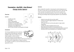
Cold-start device (choke)
The carburettor is equipped with a cold-start device to assist starting and running the engine
from cold.
As the engine warms up, the choke control is
pushed in to maintain the correct fuel/air mixture
as the fast-idling speed decreases.
Stromberg
When the choke control is pulled out, a disc (4) is
rotated and fuel flows from the float chamber
through one, two, three or four of the holes in the
disc. The fuel flow through the disc is determined
by the number of the holes that are not blanked
off. Additional airtothe disc is drawn in through
air jet (3), to form an emulsion with the fuel. The
additional fuel/air mixture then flows into the
mixing chamber through passage (6a).
(Refer to Fig. A.)
To enable the engine to run smoothly under all
driving conditions, the quantity of choke fuel is
optimized to meet the requirement during acceleration or at full throttle (Fig. A). This quantity of
fuel is much greater than that needed when the
car is travelling at a constant speed.
A leaner mixture is obtained as follows (Fig. B).
At constant speed (constantthrottle opening), a
depression is present in the inlet manifold. Via
connecting passage (8) the depression acts on
the diaphragm (1), once the force of the spring
(2) has been overcome, allowing air to be drawn
through passage (9) into the fuel inlet passage
(5). The fuel/air mixture flows through the disc
(4), where additional air is drawn in through air
jet (3). This lean mixture (6b) then flows into the
mixing chamber, providing additional fuel/air.
On renewed acceleration (opening of the throttle), the mixture is automatically enriched (loadsensing choke), since there is a reduction in the
depression in the inlet manifold, which allows
the spring loading on the diaphram to close the
air-bleed port.
Cold-start device (Stromberg)
Operating principle of the cold-start device
(Stromberg)
B
A
At constant speed
On starting, during acceleration and at full
throttle
= Fuel
= Air (at atmospheric pressure)
— Strong depression
- Weak depression
= Fuel/air mixture
1 Diaphragm
2 Diaphragm spring
3 Air jet
4 Disc
5 Fuel inlet passage (from float chamber)
6 a Fuel/air passage (rich mixture to mixing
chamber)
6 b Fuel/air passage (lean mixture to mixing
chamber)
7
8
9
10
11
Air inlet from atmosphere (as from 1984 models)
Passage to inlet manifold
Air-bleed passage
Air-bleed passage inlet from atmosphere
Fast-idiingcam
Pierburg
rhe choke disc, which is controlled by the choke
control, permits reliable starting and warm-up of
the engine, regardless of the ambient temperature. When a car is started from cold, a rich fuel/
air mixture is required at first. When the choke
control is withdrawn, the throttle (12) is partially
opened (fast idling) and the choke disc (4) is
turned to a position in which the fuel apertures
are opened.
4 Choke disc
12 Throttle butterfly
17 Modulator (lean-mixture) valve
During starting, fuel is metered from the float
chamber (A) via the fuel apertures in the choke
disc (4).
Cold starting
A Fuel supply from float chamber
Immediately after the engine has started, the
modulator valve (lean-mixture valve) (17) opens
in the inlet manifold. Thus, the air required for a
leaner mixture flows through a passage (B), from
the clean-air side of the air cleaner.
Warm starting
B Air supply
Fast idling
When the choke control is pulled out, a cam,
which acts on the throttle, is rotated. The further
the choke control is withdrawn, the faster will be
the fast idling speed.
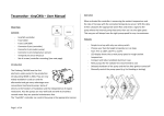
Idling (Stromberg)
The carburettor does not have a separate idling
system. At idling speed there is a depression in
the vacuum chamber. In this position the
thickest section of the tapered metering needle
is in the jet orifice and only a small quantity of
fuel, sufficient for idling, is inducted into the
cylinders. The air/fuel mixture should be set
while the engine is idling by adjusting the relationship between the metering needle and the
jet aperture. This is effected by altering the
orifice adjusting screw which raises or lowers the
tapered metering needle and it is this setting
which then covers the entire range of engine
speeds. The idling speed is changed by adjusting the setting of the throttle stop screw (idle-adjust screw). On twin-carburettor engines the
throttles can be synchronized by adjusting the
clamping bolt on the coupling assembly between
the two throttle spindles. The carburettor is
equipped with a temperature compensator to
maintain a constant fuel/air mixture regardless
of engine temperature. The temperature compensator consists of an atmospheric valve controlled by a bi-metallic strip. The valve starts to
open when the temperature of the air at the
temperature compensator reaches 68°F (20°C)
approx. Additional air is introduced through a
vent which discharges behind the airvalve shaft.
Carburettor with throttle closed (Stromberg)
1 Damper piston and oil cap assembly
2 Diaphragm
3 Compensating aperture
4 Damper piston
5
6
7
8
9
10
11
Float chamber vent.
Floatvalve
Float
Vacuum piston
Starting-fuel aperture
Throttle butterfly
Vacuum aperture
12 Needle
13 Jet orifice
14 Float chamber
15 Constant-depression chamber (CD chamber)
16 Aperture for additional air (temperature compensation)
Acceleration (Stromberg)
A damper piston is provided in the centre of the
air valve in order to provide a richer mixture when
the throttle is opened rapidly (acceleration). The
damper consists of a piston, which runs in oil, attached to a rod. When the throttle is opened
quickly the depression in the vacuum chamber
increases rapidly. When the air valve rises the
piston damper is forced against its seat preventing the oil from flowing past which retards the
movement of the air valve. This causes a temporary increase in the depression above the jet
orifice and the air/fuel mixture is enriched. The
downward movement of the air valve is springassisted.
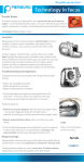
Carburettor with throttle open (Stromberg)
1 Damper piston and oil cap assembly
2 Diaphragm
3 Compensating aperture
4 Damper piston
5 Float chambervent.
6 Valve
7 Float
8 Vacuum piston
9 Starting-fuel aperture
10 Throttle butterfly
11 Vacuum aperture
12 Jet orifice
13 Needle
14 Float chamber
15 Constant-depression chamber (CD chamber)
16 Aperture for additional air (temperature compen-
sation)
Normal driving (Stromberg)
When the throttle is opened, the pressure in the
vacuum chamber, which is in communication
with the top of the diaphragm, falls, causing the
piston to rise to a new position, stabilizing the
depression in the vacuum chamber. As the
needle rises with the piston, the flow of fuel is
adjusted to the flow of air.
Idling (Pierburg)
This carburettor is not equipped with a separate
idling system. Instead, the idling mixture depends on the position of the throttle butterfly
(12), the vacuum piston (9) and the taper needle
(22) in the jet, which controls the fuel flow.
Turning the adjusting screw (27), which is in contact with the jet holder (21), alters the position of
the jet (20), thus also changing the annular gap
between the jet and the needle.
When the adjusting screw is turned clockwise,
the annular gap is reduced, thus providing a
leaner idling mixture. Turning the screw anti-
clockwise has the opposite effect.
When the engine is running, the resulting
vacuum causes fuel to be drawn into the mixing
chamber, where it is mexed with the air flowing
past the top of the jet.
The carburettor is equipped with a by-pass device for the idling mixture. Most of the idling mixture flows from the mixing chamber, past the
throttle-which is set to a minimum opening-and
into the inlet manifold. The rest of the idling mixture flows through the throttle gap, into the engine.
The bi-metal washers (23), located below the jet,
contract when the temperature of the fuel and
the surrounding metal is low.
As the temperature increases, the bi-metal
washers expand axially in the jet holder, causing
the annular gap between the jet and the taper
needle to decrease. This results in a leaner mixture at higher temperatures and a richer mixture
at lower temperatures.
This temperature compensation helps to ensure
that the optimum fuel/air ratio will be maintained, regardless of the viscosity of the fuel.
Idling
9
12
19
20
21
22
23
Vacuum piston
Throttle butterfly
Float valve
Jet
Jet holder
Needle
Bi-metal washers
27 Adjusting screw
Acceleration (Pierburg)
When the accelerator is suddenly depressed, a
richer fuel/air mixture is required briefly. This
temperary enrichment of the mixture is achieved
by means of vacuum piston spring (10) and
damper piston (8) in the damper oil (28).
When the throttle is suddenly opened, the
damper piston prevents an immediate upward
movement of the vacuum piston (9). The vacuum
of the jet (20) briefly increases, thus enriching
the fuel mixture.
Acceleration
3 Carburettor cover
7
8
9
10
20
28
Normal driving (Pierburg)
When the throttle is opened the vacuum acts on
a chamber in the carburettor cover (3), through
the compensating passages in the bottom of the
vacuum piston, and thus also on the diaphragm
(7) on the vacuum piston (9). Due to the difference between the vacuum in the chamber and
the atmospheric pressure on the underside of
the diaphragm, the piston is raised by an amount
proportional to the air flowing past the throttle,
and the cross-sectional area of the intake is increased. The air velocity and the vacuum at the
jet (20) thus remain practically constant, and
provide reliable atomization of the fuel atall engine speeds.
Diaphragm
Damper piston
Vacuum piston
Vacuum piston sprinj
Jet
Damper oil
Full-load operation (Pierburg)
The more air drawn through the carburettor, the
higher position of the vacuum piston (9) and the
needle (22). The piston reaches its highest
position at full load and maximum engine speed
and the proportional increase of the annular gap
at the jet (20) matches the fuel supply to the
amount of air being drawn in. The shape of the
needle ensures that the fuel/air ration is steplessly adjusted to the correct value under all
operating conditions.
Full-load operation
9 Vacuum piston
20 Jet
22 Needle
Engine overrun
Sweden specification
A mechanical dashpot delays the closure of the
throttle when the accelerator is released.
Sweden specification 1984 and earlier models
Europe specification (1984 and earlier
models)
The carburettor is equipped with a diaphragm
valve which is affected by the manifold depression during overrun, thereby opening the throttle
by-pass and permitting the correct air/fuel mixture to reach the engine.
Deceleration valve, normal driving
1Adjusting screw
2 Rubber ring
3
4
5
6
Cover
Nut
Spring
Passage to diaphragm upper side
Deceleration valve, engine overrun
7 Diaphragm
8
9
10
11
Valve
Throttle
Air/fuel mixture inlet passage
Air/fuel mixture outlet passage
1985 models onwards
A poppet valve is incorporated in the throttle butterfly. On engine overrun, the valve opens a port
in the butterfly, allowing the correct mixture of
fuel and air to be admitted to the engine.
Deceleration valve, normal driving
Deceleration valve, engine overrun
1 Poppet valve
2 Spring seat
3 Spring
4 Spring seat
Idling shut-off valve
Carburettor engines are equipped with an idling
shut-off valve to eliminate the engine running on
after the ignition has been switched off.
Single carburettor engines obtain their air/fuel
mixture at idling speed through a small aperture
in the throttle butterfly and through a throttle bypass passage. When the ignition isturned off the
by-pass passage is blocked by a spring-loaded
solenoid which is then deprived of its electric
current. The air/fuel mixture can now only pass
through the aperture in the throttle butterfly,
which is insufficient to keep the engine running,
which therefore stops.
Idling shut-off valve, single carburettor
Twin carburettor engines incorporate a solenoid
valve which regulates communication between
the section of the float chamber above the fuel
level and the constant-depression (CD)
chamber. When the ignition is switched off, a
time relay closes a circuit which causes the solenoid valve to open the connection to the float
chamber, giving rise to a depression above the
fuel level. This eliminates the pressure difference, needed for fuel to be drawn through the
needle valve, and the engine therefore stops.
Current to the solenoid flows for a limited time
only; after six seconds, therefore, with the engine-idle, the relay will be de-energized.
Idling shut-off valve, twin-carburettors
Stromberg carburettors (as from 1984
models)
Preheated air for cold-start device (choke)
As from 1984 models, the induction air for the
cold-start device is preheated. The preheated air
enters the air intake hose to the carburettor and
flows through a hose to the cold-start device.
When the air is preheated, condensation is reduced, with a consequent reduction in the risk of
moisture freezing in the system.
Outlet for EGR valve
In conjunction with the introduction of the EGR
system, the carburettor has been equipped with
two vacuum outlets. The outlet marked 'E' is connected to the pressure upstream of the throttle
butterfly. This outlet is for control of the EGR
valve. The other outlet is in communication with
the pressure downstream of the throttle butterfly
and is connected to the vacuum control unit on
the distributor.
Stromberg
1 Outlet for EGR valve
2 Vacuum control unit (distributor)
Pierburg
1 Outlet for EGR valve
2 Vacuum control unit (distributor)
Air cleaner
The air cleaner is positioned at the front of the
left wheel housing and is connected to the carburettor by means of a hose. Its purpose is
twofold: to clean the air inducted into the engine
and to reduce the noise caused by the induction
system. The air cleaner element, which is made
of a special grade of paper, must not be washed
or wetted, but should be replaced at the
specified service interval.
Air preheating
A thermostatic valve, situated in the air cleaner
intake, regulates the temperature of the induction air.
There are two air intakes in the valve housing:
one for cold air and one for heated air. The
heated air is drawn in through an insulated hose
from a hot spot on the exhaust manifold.
On 1985 and earlier carburettor engines, the
valve is activated by a thermostat in front of the
carburettor. The thermostat senses the temperature of the pre-mixed induction air and maintains
it at 23-37°C (73-98°F) by means of a cable. In
operation the valve therefore alternates between
the non-preheated and preheated position.
As from 1986 models, the valve butterfly in carburettor engines is controlled not only by a thermostat but also by a bimetallic strip in the air induction hose upstream of the carburettor. The
bimetallic strip senses the temperature of the induction air and uses the depression in the inlet
manifold to operate the valve butterfly. When the
engine is under full load, and the depression in
the inlet manifold is weaker, the butterfly is controlled by the thermostat. This system ensures
that the induction air to the engine is always at
the correct temperature of 25 ± 5°C {77 ± 15°F).
1 Valve housing
2 Cold-air intake
3 Preheated air intake
4 Valve butterfly
Fuel pump
The fuel pump is a diaphragm pump, driven by a
push-rod from an eccentric on the camshaft.
Apart from the filter, which can be removed for
cleaning (up to engine No. D 052892), the pump
cannot be dismantled for overhaul or repair.
1 Fuel pump body
2 Adaptor
5
6
7
8
9
Thermostat body
Bimetallic strip
Inlet manifold
Carburettor
Crankcase ventilation
3 Push-rod
4 Seal
5 Filter
6 Cover
Fuel tank
The fuel tank, made of injection-moulded plas-
tic, houses the fuel gauge sender unit, the pump
inlet line and a connection for the fuel return
line.
The tank is equipped with a breather system and
overfill protection, which allows for expansion of
the fuel inside the tank.
Fuel tank venting and overfill
protection
When fuel is added to the tank air is evacuated
partially through breather pipe 3. An air cushion
is formed at the top of the tank when the level of
fuel reaches the lower opening of the breather
pipe (3), owing to the action of a restriction (5)
positioned in the breather hose for the upper
section of the tank (4). The restriction hinders
rapid changes in volume when the car is being refuelled but does not affect gradual changes in
volume occasioned by temperature changes or
movement of the car.
The tank is vented externally through the vent
hose (6) which runs from the filler pipe up the
rear corner pillar and along the roof (above the
headlining) down through the left front corner
pillar and opening into the engine compartment.
In cars produced as from the latter half of the
1985 model year, the vent hose is connected to
a spigot on the outer end of the filler pipe.
Under normal conditions, the filler cap makes a
tight seal with the filler pipe. However, the cap
incorporates a vacuum valve which will prevent
the fuel tank from collapsing as a result of the
pressure difference that could arise if the ventilation system should become blocked.
Fuel lines
The fuel system includes both plastic and rubber
fuel lines. Plastic pipes are used for runs through
the body, and rubber hoses for connections to
the fuel tank, fuel pump and carburettor.
The fuel supply and fuel return lines, which run
together between the fuel tank and fuel pump,
are routed along the rear-seat member and LH
side member.
Body lead-throughs are sited to the left in the
bulkhead panel and to the right in the floor-pan
pressing for the rear axle. The lines enter the engine compartment through the LH wheel-arch
bracket.
Return fuel
Surplus fuel is returned to the fuel tank via the
fuel return line, which is connected to a restriction-type branch connector between the fuel
pump and the carburettor. As from 1986 models,
the fuel return line is connected to the fuelreturn outlet on the vapour trap.
Fuel tank ventilation and breather system
1 Fuel tank
2 Filler pipe
3 Breather pipe
4 Breather hose
5 Restriction
6 Vent hose
7 Filler cap
8 Vacuum valve
9 Expansion space
10 Fuel return line
Roll-over valve
1984 model cars onwards are equipped with a
roll-over valve. The valve is connected to the vent
hose for the fuel tank and prevents petrol escaping in the event of the car being involved in a collision.
The valve is located on the right-hand side in the
luggage compartment, mounted on the reinforcement panels inside the rear wing.
Location of the roll-over valve
1 Fuel tank
2 Roll-over valve
Carburettor
Single carburettor (Stromberg)
Removal
Dismantling
Cleaning
Assembly
Refitting
Twin carburettors (Stromberg)
Removal
Dismantling
Cleaning and assembly
Refitting
Single carburettor (Pierburg)
Removal
Dismantling
Cleaning
Assembly
Refitting
231-1
231-2
231-3
231-4
231-7
231-8
231-9
231-11
231-12
231-27
Float chamber vent valve
231-28
Idlingshut-off
231-30
Engine run-on
231-31
Checking and adjusting
Choke (twin carburettors)
Choke control (Pierburg)
Fast idling (Pierburg)
Choke (Pierburg)
231-31
231-32
231-33
231-33
Basic setting of
231-13
231-15
231-16
231-16
231-19
Changing the adjusting screw in
the vacuum piston (Stromberg)
231-20
Checking and replenishing
damper oil
231-22
Changing the jet
231-23
Basic setting of metering
needle
231-24
Temperature compensator
(Stromberg)
231-25
Choke modulator (Stromberg)
231-27
Single-carburettor (Stromberg)
Removal
1 Disconnect the inlet hose from the carburettor.
2 Disconnect the fuel line, throttle and choke
control cables and vacuum hose to the distributor.
3 Remove the screw for the dipstick tube.
4 Back off the four retaining nuts and lift off
the carburettor.
Checking the modulator
valve and hose (Pierburg)
needle (Stromberg)
Checking the needle
(Pierburg)
Synchronization of
twin carburettors
231-34
231-35
231-35
CO setting (Stromberg)
231-36
CO setting (Pierburg)
231-40
Fault diagnosis-high CO
value
231-43
Adjustingscrews (twin
carburettors)
231-44
Choke
231-45
Vapour trap
231-47
Dismantling
Tools: Adjusting tool 8393035
1 Remove the vacuum chamber cover (1) and
spring (2).
2 Remove the piston (6) with the diaphragm
(5).
Carburettor
1 Vacuum chamber cover
2 Spring
3
4
5
6
Metal retaining ring
Plastic washer
Diaphragm
Vacuum piston
7 Metering needle
3 Remove the needle as follows:
a Slacken the setscrew.
b Turn the adjusting screw counterclockwise, using tool 83 93 035, until the
needle is free. Backoff the setscrew until
it is clear of the needle shoulder, then remove the needle.
4 Remove the screws, retaining ring (3), plastic washer (4) and diaphragm (5).
Carburettor
1Vacuum chamber cover
2 Spring
3 Metal retaining ring
4 Plastic washer
5 Diaphragm
6 Vacuum piston
7 Metering needle
5 Remove the float chamber (8).
6 Carefully disengage the float spindle from
the retaining clips and remove the float (9).
7 Remove the float valve (10) and washer.
8 Remove the cold start mechanism (11).
9 Remove the temperature compensator (13)
and the rubber gaskets (14).
8
9
10
11
Float chamber
Float
Float valve
Cold start assembly
12 Carburettor body
13 Temperature compensator
14 Rubber gaskets
Cleaning
Wash the carburettor parts in paraffin.
Caution
The diaphragm should only be cleaned with
paraffin.
Avoid using volatile cleaning agents such as
trichloroethylene.
Check that the diaphragm is in good condition. If
the diaphragm is cracked, it should be replaced.
Check the needle for wear; bent or worn needles
should be replaced. Check that the contact and
sealing surfaces are not damaged. Clean the
hole in the choke valve disc by means of compressed air. Clean the temperature compensator
and check that the valve moves freely.
Refer to the separate sections on the needleadjusting screw, jet, temperature compensator
and float-chamber ventilation.
Assembly
Tools: Adjusting tool 83 93 035
Vernier calliper
1 Fit the diaphragm on the vacuum piston so
that the inner locating tab engages the corresponding slot in the piston (A).
Note
If, after having been allowed to dry for a while,
the diaphragm is still so distended that it will not
fit into the piston, renew it. A distended diaphragm will usually revert to its original form
after a while.
Place the plastic washer (4) and retaining
ring (3) carefully in position, lining up the
screw holes with those in the piston and
diaphragm, without turning the ring, and
match ing the notches in the ring with the tab
on the diaphragm.
A Inner tab and matching slot in vacuum piston
B Outer tab to match slot in carburettor body.
2 Fit the needle as follows:
a Insert the spring housing of the needle
into the vacuum piston. Screw in the
setscrew until the spring-loaded pin
drops into the groove in the side of the
spring housing.
b Screw the spring housing onto the adjuster by turning the adjuster with Alien-key
tool 83 93035.
c Adjust the position of the needle, which is
correct when the needle shoulder is flush
with the bottom of the piston.
d Tighten the setscrew.
This position Is the basic setting for subsequent
CO adjustment.
Needle shoulder flush with bottom of piston
3 Install the piston complete with diaphragm
and spring in the carburettor body. Make
sure that the outer tab on the diaphragm engages the matching slot in the carburettor
body. Place the vacuum chamber cover carefully in position, aligning the marks. The
groove and locating rim should be a good fit;
if not fit a new part. Tighten the screws.
4 Fit the float valve and washer, and assemble
the float and spindle. The flat side of the
float faces away from the carburettor body.
5 Check the float level as follows:
a To check the float level the carburettor
must be removed from the engine and in-
verted with the float chamber and gasket
off.
b For the level to be correct the highest
point of the float should be 16-17 mm
{0.63-0.67 in) above the flange of the
carburettor body (gasket removed) when
the float valve is closed. If the level is not
correct, adjust by bending the end tab at
the float valve.
Note
Do not bend the arm between the float and the
spindle.
6 Fit a new gasket and the float chamber. First
insert all screws and give them a few turns,
then push down the float chamber until it
butts firmly and tighten the screws.
7 Fit the cold start mechanism. If the
mechanism has been dismantled, fit the
choke disc, spindle and cam lever as illustrated. The calibrated holes should face
away from the cable linkage.
8 Check the setting of the temperature compensator and that it operates freely (see
section "temperature compensator") and
mount it together with the rubber gaskets.
To refit
1 Fit the inlet manifold gasket.
2 Fit the carburettor into the inlet manifold.
3 Connect the fuel line, throttle cable and
choke cable, and the vacuum hose to the
distributor.
4 Fit the dipstick tube mounting bolts.
5 Connect the inlet hose to the carburettor.
6 Fill the damper cylinder with oil: the oil level
should be within 10mm (0.394 in) of the top
of the damper cylinder.
7 Set the idling speed and CO content
Twin-carburettors (Stromberg)
To remove
1 a Up to and incl. 1982 models:
Unclip the four wire clips holding the air
box cover, loosen the air cleaner hose clip
and remove the cover together with the intake hose.
b As from 1983 models:
Remove the air box cover retaining
screws and the cover on the dipstick tube.
Lift up the toggle fastener for the dipstick
tube. Slacken the hose clip at the air
cleaner and remove the cover complete
with intake hose.
2 Disconnect the throttle and choke cables
from the carburettors.
3 Remove the clips from the choke linkage and
remove the linkage from the operating rod.
4 Remove the air box retaining screws and remove the box, the throttle cable bracket, the
choke lever and the gaskets.
5 a Undo the clips and disconnect the fuel
pipe.
b Remove the suction hoses from the carburettors.
6 Remove the carburettor retaining nuts and
lift out both carburettors simultaneously.
Dismantling
Tools: Needle adjusting tool 83 93 035
1 Remove the vacuum chamber cover (2) and
spring (3).
2 Remove the vacuum piston (6) and diaphragm (5).
Carburettor
1 Damper and oil cap assembly
2
3
4
5
6
7
Vacuum chamber cover
Spring
Retaining ring
Diaphragm
Piston
Metering needle
3 Remove the metering needle as follows:
a Back off the setscrew.
b Turn the adjusting screw inside the
damper counter-clockwise using adjusting tool 8393035 until the needle is
free.
Back off the setscrew until it is clear of
the needle shoulder, then remove the
needle.
4 Remove the screws, aluminium retaining
ring (4) and diaphragm (5).
Exploded view of twin carburettors (A)
1 Damper and oil cap assembly
2 Vacuum chamber cover
3 Spring
4 Retaining ring
5 Diaphragm
6 Piston
7 Metering needle
5 Remove the float chamber (9).
6 Carefully separate the float spindle from the
retaining clips and remove the float (8).
7 Remove the float valve and washer.
8 Remove the cold start mechanism (10).
9 Remove the temperature compensator (11).
Save both rubber gaskets (12).
Exploded view of twin carburettors (B)
8 Float
9 Float chamber
Cold start mechanism
Temperature compensator
Rubber seals
Idling speed adjusting screw
10
11
12
13
Cleaning and assembly
The procedure for cleaning and assembly of the
carburettors is the same as for the single carburettor (see page 231-3)
Idling adjustment screw Europe specification as
from year model 1984
To refit
1 Fit the two gaskets with the insulation between them to each of the inlet manifold
flanges (as shown).
2 Mount the two carburettors simultaneously
and secure by means of the nuts and
washers. Ensure that the springwhich keeps
the rear carburettor arm and adjusting screw
in contact with the arm of the front carburettor is fitted.
3 a Connectthefuel line andfitthe clips,
b Connect the vacuum hose.
4 Fit the gaskets, bracket, air box and flange
washers to the carburettors.
5 Fit the choke links to the connecting rods
andfitthe clips.
6 Connect the throttle and choke cables.
Single carburettor (Pierburg)
To remove
Disconnect the positive {+) lead from the battery.
1 Disconnect the hoses to the EGR valve and
distributor.
2 Disconnect the earth lead from the top of the
carburettor.
3 Disconnect the electrical lead from the float
chamber ventilation shuft-off valve.
4 Disconnect the accelerator and choke
cables.
5 Disconnect the inlet hose from the carburettor flange.
6 Remove the flange and the gaskets.
7 Remove the fuel hose from the carburettor,
complete with vapour trap and clamp.
8 Unbolt the carburettor from the flange on the
inlet manifold.
To dismantle
1 Remove the damper piston (1) and the cover
(2).
2 Remove the carburettor cover (3) and the
spring (4).
3 Remove the vacuum piston (8) and diaphragm (7).
4 Release the setscrew and remove the
needle (9) from the piston.
5 Remove the diaphragm (7) from the piston
(8) by removing the screws, the retaining
ring (5) and the plastic washer (6).
Carburettor
1 Damper piston
2 Cover
3 Carburettor cover
4 Spring
5 Metal retaining ring
6 Plastic washer
7 Diaphragm
8 Piston
9 Needle
A Passage under vacuum piston
B Float chamber vent passage
6 Remove the float chamber cover (10).
7 Remove the jet (15) and the spring (16).
8 Remove the plastic bracket (17) for the
float, and then remove the float (11).
9 Remove the float valve (12) and the washer.
10 Remove the choke (13).
11 Remove the modulator valve (18).
10
11
12
13
Float chamber cover
Float
Float valve
Choke mechanism
14 Carburettor body
C
D
E
F
15 Jet
16 Jet spring
17 Plastic bracket
18 Modulator valve
Signal outlet for distributor
Signal outlet for EGR
Fuel inlet spigot
Modulator valve spigot
To clean
Wash the carburettor components in paraffin
{kerosine).
Note
Clean the diaphragm in paraffin (kerosine) only.
Do not use highly-volatile cleaning agents such
astrichlorethylene.
Check that the diaphragm is in good condition. If
it has split, fit a new one.
Check the needle for wear and replace it if it is
bent or worn. Check that all contact and sealing
surfaces are undamaged.
Check that the choke disc and corresponding
sealing surface on the carburettor body are not
scratched. Clean the holes in the choke disc with
compressed air.
To assemble
1 Fit the diaphragm on the vacuum piston so
that the inner locating tab (A) engages the
corresponding slot in the piston.
Note
If, after drying for a while, the diaphragm is still
so distended that it will not fit into the slot, renew
it. A distended diaphragm will usually revert to its
normal shape after being allowed to dry for a
while.
Place the plastic washer and metal retaining
ring in position so that the screw holes are in
line with those in the piston and diaphragm,
without twisting the ring, and with the notch
matching the tab on the diaphragm. Fit and
tighten the screws.
A Innertaband matching slot in vacuum piston
B Outer tab to match slot in carburettor body
2 Fit the needle as follows:
a Insert the spring housing of the needle
into the vacuum piston, with the flat surface facing the setscrew.
b Adjust the needle so that the shoulder is
flush with the bottom of the piston.
Needle should flush with bottom of piston
c Tighten the setscrew.
Fit the float valve and washer and the float
and spindle. Make sure that the adjusting
tab on the float is inserted under the locking
needle of the float valve. Fit the plastic bracket.
4 Check/adjust the float level
Press down on the plastic bracket to position
the float correctly. Tilt the carburettor (approx. 10°) until the float arm just touches the
ball on the needle valve.
Note
The ball must not be pressed home.
Measure the float height to the gasket face.
Adjust the height, as necessary, to the correct value of 8 ± 1mm by bending the tab at
the needle valve.
5 Fit the jet spring and the jet.
6 Fit the float chamber cover.
7 Carry out basic setting of the fuel jet.
Adjust the height by means of the adjusting
screw on the float chamber cover. The jet should
be 2,5 mm (0.098 in) below the face of the jet
bridge (at 20°C;68°F).
Note
Take care not to press down on the spring-loaded
jet with the calliper, as this will affect the readins.
8 Fit the piston, with the diaphragm and
spring, into the carburettor body. Make sure
that the tab on the diaphragm fits into the
corresponding slot in the carburettor body.
Fit the carburettor cover in position as indicated by the marks, and tighten it.
9 Fit the cover and the damper piston.
10 Fit the modulator valve.
11 Fit the choke.
To refit
1 Fit the carburettor to the rubber of the inlet
manifold.
2 Connect the fuel hose to the carburettor and
fit the vapour trap and clamp.
3 Fit the flange to the carburettor.
4 Connect the inlet hose to the carburettor.
5 Fit the throttle and choke cables.
6 Connect the electrical lead to the float
chamber ventilation shut-off valve.
7 Fit the earth lead to the top of the carburettor.
8 Connect the hoses for the EGR valve and distributor.
9 Fill the damper cylinderwith oil.
10 Run the engine until it reaches normal
operating temperature and then adjust the
CO setting, idling speed and fast idling
speed.
Changing the adjusting screw
in the vacuum piston
(Stromberg)
Removal (vacuum piston with needle
removed)
1 Using a drift, press out the adjusting screw
until it protrudes a few centimetres (an inch
or so) beyond the bottom of the piston.
2 Press in the adjusting screw again.
3 Rock the retaining washer to loosen it and
then remove it by means of a bent piece of
wire. The adjusting screw can now be removed.
Refining
1 Using a drift, press the adjusting screw with
'0' ring into the piston.
NOTE
Grease the '0' ring with Vaseline or the equivalent to prevent the ring from being damaged on
fitting by any scoring on the cylinder bore.
2 Press a new retaining washer into the
damper cylinder using a drift.
Saah QIWI
To check and top up the oil in
the damper cylinder
Check the oil level, which should be 10 mm (0.04
in) below the top of the cylinder. Top up, as
necessary, using automatic transmission oil.
Pierburg carburettor
To check the damper piston
Check for damage and wear.
Check the axial play of the damper piston, which
should be between 0.5 mm and 1,5 mm (0.02 0.06 in).
In case of any defect, replace the entire damper
piston and oil cap assembly.
Check that the vent hole in the oil cap is open.
Changing the jet
Stromberg
Tools:
Drift 83 92 789
The jet is press-fitted in the carburettor body and
should not be moved from the specified position.
However, the jet can be changed using tool
83 92 789 as follows.
1 Remove the carburettor and then take off the
vacuum chamber cover and remove the vacuum piston and float chamber cover. ,
2 Tap out the jet using tool 83 92 789.
3 Using the tool, tap in the new jet from the
float chamber side, using drift 8392789,
until the distance of the jet below the level of
the bridge in the carburettor body is as follows:
Single carburettors: 2,5 ±0,1 mm
(0.0984 ±0.0039 in)
Twin carburettors: 2,3 ±0,1 mm
{0.0906 ±0.0039 in)
If you happen to tap the jet in too far, it can
be tapped back from above using the same
tool.
Caution
Avoid resting any type of measuring tool against
the upper, inner surface of the jet when tapping
it into position. Even the si ightest deformation in
the surface can affect the jet orifice.
Plerburg
To remove
1 Remove the carburettor from the car and
then remove the damper piston and carburettor cover.
2 Empty all fuel from the carburettor.
3 Remove the float chamber cover.
4 Remove the jet and the return spring.
Tom
1 Fit the return spring and the new jet.
2 Refit the float chamber cover complete with
gasket.
3 Adjust the height of the jet (see below).
4 Fit the carburettor cover and damper piston.
5 Refit the carburettor.
Basic fuel-jet setting (Pierburg)
When measuring, remember that the jet is
spring-loaded.
Adjust the height by means of the adjusting
screw in the float chamber cover.
The jet should be set 2,5 mm (0.098 in) below
the face of the bridge in the carburettor body.
Temperature
(Stromberg)
compensator
The temperature compensator serves to maintain a constant fuel/air mixture, regardless of the
ambient carburettor temperature. The temperature compensator valve is governed by a bi-
metallic strip which, on heating, opens an air
passage past the vacuum piston. The valve
opens at around 20°C (68°F).
In the event of the idling speed dropping rapidly
after prolonged idling, particularly in warm
weather, check the operation of the temperature
compensator by removing the plastic cover and
pressing in the valve, whereupon the tickover
should become less smooth. If the valve is stiff
or sticks it can be adjusted, provided that it is not
scratched or coated with deposits. Should this
prove to be the case, fit a new valve.
Adjustment
Note
The temperature compensator is adjusted at the
factory and should therefore not be tampered
with unless absolutely necessary.
Back off the bi-metallic strip retaining screw
slightly and centre the valve by pressing it to-
wards its seating. Retighten the screw.
Setting
At 20°C (68°F) the valve should have opened 0,1-
0,3 mm (0.004-0.012 in). To check the setting,
the temperature compensator should be removed from the carburettor and kept at a temperature of 20°C (68°F) until it has acquired this temperature. Setting is by means of the bi-metallic
strip adjusting nut.
Temperature compensator
1
2
3
4
5
6
7
Changing
Change the temperature compensator as a
complete unit. To remove it, undo the two slotted
screws.
Note
Both the outer and inner rubber gaskets must be
exchanged.
Air passage
Valve
Bi-metallic strip
Adjusting nut
Bi-metallic strip retaining screw
Seal
Jet bridge
Choke modulator (Stromberg)
To check
1 Connect exhaust extraction equipment and
a CO meter.
2 Start the engine and run it up to normal
operating temperature.
3 Pull the choke control out to about one-third
of its travel.
4 Use a finger or a piece of fabric tape to seal
off the filter orifice in the choke modulator.
Note
The filter orifice must be tightly sealed. If the
choke modulator is working properly, the CO
value will increase markedly.
To check the modulator valve
and hose (Pierburg)
Suck at the valve and check that it opens and
closes.
Check that the hose is intact and that it is still
flexible and soft.
The valve can also be checked as follows when
the CO content is checked.
Run the eingine at fast idling speed.
Disconnect the hose from the valve and plug it,
whereupon the CO valve should increase. Reconnect the hose, whereupon the CO valve should
fall.
If there is no change in the CO content, fit a new
valve or remove the valve and blow clean the passages with compressed air.
Float chamber vent valve
Checking and setting
Stromberg
The valve should be set so that atmospheric air is
drawn in through the connection to the air
cleaner.
1 Connect a hose to the mouth of the atmospheric air pipe.
2 Blow down the hose. If the fuel pipe is notfitted and connected to the pump, the fuel
inlet connection must be sealed off.
a With the throttle fully closed it should not
be possible to blow through the connection {as the float chamber is an enclosed
space).
Throttle valve fully closed
1 Airfrom air cleaner
2 Atmospheric air
b If the throttle is opened 2-3 mm (0.080.112 in) (at the throttle stop) a passage
will be opened for internal air flow, making it possible to blow through the connection.
Throttle valve open 2-3 mm (0.08 - 0.112 in)
c If the throttle is opened a fraction more,
the passage should close again.
Throttle valve open a fraction more,
3 Release the locknut and adjust the valve by
rotating the setting screw. Use the procedure outlined in steps 2a and 2b.
4 The idling speed, CO setting and synchronization (twin carburettors only) must be
checked following the above adjustments
and reset if necessary.
Plerburg
Switch on the ignition and pull off the plug on the
electrical connector to the valve, which should
cause a clicking sound to be heard.
Idling shut-off
To check single carburettor engines
1 Connect a tachometer and let the engine run
at idling speed.
2 Temporarily disconnect the lead from the
shut-off valve and check that the idling
speed drops by at least 200 r/min.
Note
The engine will run on after the ignition has been
turned off if the idling speed is too high.
To check twin-carburettor engines
Disconnect the standard and blow into the connections for the float chamber vent valves:
a With the ignition turned on, or about 6
seconds after the igni tion has been
switched off, the float chambervent valve
should allow the entry of air from the atmosphere.
b The
connection
between
the
float
chamber and the passage to the vacuum
chamber should open within approx. 6
seconds of the ignition being turned off.
Engine runs on
The likely causes of the engine running on are as
follows:
• Idling speed settoo high.
• Ignition timing too far advanced.
• Mixture in carburettor too weak (idling).
These three factors tend to produce a wider
opening of the throttle butterfly.
• Carbon deposits in combustion chamber
(caused by prolonged use of choke and engine
failing to reach normal running temperature).
• Grade of fuel too low - higher octane rating
needed.
• Float chamberventilation incorrectly adjusted
(twin carburettors only).
Checking and adjustment
Choke Control (Twin carburettors)
Check that both choke controls strike their stops
at the same time. If necessary, adjust the control
spindle linkages.
Fast idling (Stromberg)
Check the fast id I ing speed with the engine warm
as follows:
(Vacuum line to distributor plugged.)
a Place an 8 mm (0.315in) dia. spacer
(drill bit) between the notch in the cam
lever and the stop on the choke housing.
b Check that the fast idling speed is correct.
Adjust the stop screw on the throttle lever
if required.
Code on
r/min
CM 81-82
CM 83
CA.CM84-
1100 ± 50
1350 ± 50
1350 ± 50
1100 ± 50
fast-idling
cam
TMJA81-84
"A6"
"A8"
"ASA"
"A5"
Note
If the code on the cam differs from that shown for
a given engine variant, follow the setting applicable to the cam code.
Choke control (Pierburg)
Make sure the lever deflects fully when the choke
is pulled out.
Push in the choke. Make sure the lever is at the
lower limit of its travel and that the fast idling
screw is not touching the lever.
Adjust as necessary.
Fast idling (Pierburg)
Note
Disconnect the vacuum line to the distributor
and run the engine to normal operating temperature.
Pull out the choke until the mark on the choke
lever is in line with the fast idling screw.
Adjust the engine speed to 1350 ± 50 r/min by
means of the fast idling screw.
Choke (Pierburg)
Make sure the choke does not bind.
Check the valve disc and the corresponding sealing surface on the carburettor body.
Remove any minor scratches using fine emery
cloth and lapping paste.
Basic setting of metering needle (Stromberg)
Tools: Needle adjusting tool 83 93 035
As regards twin carburettors, the basic setting
must be adjusted on both. The jet is fixed in the
carburettor and the height of the needle must
therefore be adjusted to effect the basic setting.
Proceed as follows.
1 Remove the damper and oil cap assembly.
2 Remove the.vacuum chamber cover and the
return spring.
3 Withdraw the piston and diaphragm together.
4 Using tool 83 93 035, bring the should of the
needle in line with the lower edge of the vacuum piston.
Needle should flush with bottom of piston
5 Fit the piston and diaphragm complete in the
carburettor, making sure that the outer tab
on the diaphragm engages the matching
slot in the carburettor body.
6 Fit the spring and vacuum chamber cover,
making sure that the marks coincide, and
then fit and tighten the screws.
7 Check and if necessary fill oil in the damper
cylinder and fit the damper piston.
Fine adjustment of the setting is effected in conjunction with the subsequent CO check.
To check the needle (Pierburg)
Check the needle for signs of wear or damage
and also the needle setting.
Release the setscrew to adjust the height of or to
replace the needle.
Make sure that the flat in the needle shoulder is
towards the setscrew.
The needle designation is stamped on the
needle and can be seen after the needle has
been withdrawn from the socket (needle shoulder).
To synchronize twin carburettors
1 Run the engine to normal operating temperature and then let it idle. The idling speed
adjusting screw serves both carburettors
and is located on the front carburettor. Location of idling speed adjusting screw, 1984
Europe spec, models onwards.
Placement of adjusting screw, Europe specification, as from year model 1984
Synchronize the carburettors by means of
the adjusting screw on the linkage between
the two carburettors. Compare the air flow
through the carburettors by means of a synchro-tester. The adjusting screw should be
locked by means of the locknut after setting.
CO-setting (Stromberg)
Before adjusting the CO setting:
lChange the engine oil.
2 Check the condition of the spark plugs.
3 Check the HT leads.
4 Check the valve clearance.
5 Check the position of the camshaft (timing) .
6 Check the ignition timing.
7 Check the idling speed.
8 Check the float chamber ventilation.
9 Checktheoil level inthecarburettordashpot
damper.
10 Check the air preheater/air cleaner.
11 Check the delay valve.
12 Check the radiator fan.
13 Check the fuel shut-off valve.
14 Check the fast-idling speed (engine at normal running temperature).
15 Check the operation of the choke modulator
by blanking off the filter aperture.
16 Check that the secondary CO adjusting
screw is screwed fully home.
Note
To minimize the possible effect on the readings
caused by various engine and exhaust emission
control components, the CO setting on cars with
Sweden specifications (and Switzerland, as from
1983 models) should be carried out at an engine
speed of 2000 r/min. On Europe spec, cars, the
setting should be made at idling speed.
CO-setting at 2 000 r/mln
1 Run the engine to normal temperature, con-
nect a tachometer and set the speed to
2000r/min.
2 Disconnect the crankcase ventilation as follows:
A Disconnect the hose from the valve cover.
B Plug the end of the small-bore hose.
C Connect the evacuation hose to the valve
cover.
Evacuate the crankcase gases from the outlet in the valve cover by connecting the other
end of the hose to the evacuation hose of the
building's extraction system, at a point
downstream of the CO-meter probe, to ensure that the readings will not be affected.
Note
When connecting exhaust extraction equipment
in conjunction with running the engine inside the
workshop, avoid excessive depressurization of
the exhaust system, as this may affect readings,
e.g. of the CO content.
To prevent excessive extraction pressure, use an
extraction hose with an open coupling.
Secondary CO adjusting screw (single carb.)
Carburettors equipped with a secondary CO adjusting screw for use at idling speed are fitted to
single-carburettor cars as from engine no.
18191, Conventional adjustment of the CO content should be carried out as before at 2,000
r/min.
Note
In its normal setting, the secondary adjusting
screw should be screwed right home, to the end
of its travel. If during subsequent checking of the
CO value at idling speed the value exceeds the
specified maximum(4.5%), the CO content can
be reduced using the secondary adjusting screw.
3 Disconnect the vacuum line from the distributor and blank off the end of the hose.
4 Plug the end of the vacuum hose to the EGR
valve (where applicable).
5 Connect the CO meter and tachometer.
6 Switch on the daylight driving lights.
7 Read the CO value immediately after the
radiator fan cuts in. If the reading is within
the specified limits, reset the idlingspeed to
850 r/min.
Idling adjustment screw Europe specification as
from year model 1984
CO-setting at 2 000 r/min
(Hoses to vacuum control unit, crankcase
ventilation and EGR valve disconnected.)
Single carburettor:
1.75 ±0.25%
Twin carburettors:
1.010.25%
For adjustment, remove the dashpot damper
pistons and then turn needle adjusting
screwsby means of tool 8393035. Support
the vacuum piston by means of the sleeve of
the tool to prevent the rubber diaphragm
from being damaged.
Rotate clockwise to Increase CO-value
(needle raised).
Rotate counter-clockwise to reduce COvalue (needle lowered).
8 Remove the plugs and connect the crankcase ventilation, the EGR hose and the vacuum hose to the distributor.
9 Set the idling speed to 850 ± 50 r/min and
check the CO-value.
Maximum CO reading at idling speed
Sweden 4.5%
Europe 3.5%
CO setting at 850 r/min (Idling speed)
1 Run the engine until it reaches its normal
running temperature, so that the CO reading
can be made just after the fan has cut in. The
reading must be made with the headlights
switched off.
Connect the CO meter and tachometer.
2 Check the idling speed, adjust as necessary
and then read off the CO value.
Refer to the 'Technical data' section for the
correct CO reading at 850 r/mln
Toadjust: Remove the damper piston (orpistons) and then use tool 83 93 035 to turn the
needle adjusting screw. Use the sleeve of
the tool to support the vacuum piston, to
prevent damage to the diaphragm.
Turn the screw clockwise to increase the
reading (needle raised).
Turn the screw counter-clockwise to red uce
the reading (needle lowered).
3 Disconnect the CO meter and tachometer.
CO setting
Before adjusting the CO setting:
lChange the engine oil.
2 Check the spark plugs.
3 Check the HT leads.
4 Check the valve clearances.
5 Check the position of the camshaft (timing).
6 Check the ignition timing.
7 Check the float chamber ventilation.
8 Check the oil level in the damper cylinder.
9 Check the air preheater/air cleaner.
10 Check the delay valve (for vacuum control
unit on distributor)
11 Check the radiator fan.
12 Check the fuel shut-off valve.
If the car has been taken into the workshop after
having been outdoors at ambient temperatures
below -10 C (14 F) and the fuel is thus cold, proceed as follows:
• Pinch closed the fuel return line at the carburettor until adjustment of the CO emission
has been completed.
• Run the engine with the bonnet (hood) closed
until the radiator fan has cut in.
To check
1 Run the engine to normal temperature and
connect a tachometer.
2 Disconnect the crankcase ventilation as follows:
a Disconnect the nipple from the valve
cover.
b Plug the small-bore hose.
c Connect an evacuation hose to the valve
cover.
Evacuate the crankcase gases by connecting a hose from the opening in the valve
cover to the evacuation hose of the building's extraction system, at a point
downstream of the CO meter sensor.
Note
When connecting exhaust extraction equipment
for running the engine in the workshop, make
sure that the resultant depression in the exhaust
system is not too high, as this may affect the
readings of the CO content.
To prevent excessive suction, use an extraction
hose with an open coupling.
3 Disconnect the vacuum hose from the EGR
valve and plug the hose.
4 Disconnect the vacuum hose from the vac-
uum control unit on the distributor and plug
the hose.
5 Connect the CO meter.
6 Adjust the engine speed to 2 000 r/min.
7 Ensure that the choke control is pushed in.
8 Read the CO value immediately after the
radiator fan cuts in.
CO setting value at 2 000 r/min: 1.7 ±0.3%
To adjust the CO setting
Adjust the CO emission by means of the adjusting screw on the float chamber cover.
The screw is sealed with a plastic plug. Prise out
the plug with a screwdriver and fit a new plug
after making the adjustment.
• Turn the screw clockwise (in) to reduce the CO
content.
• Turn the screw anti-clockwise (out) to increase the CO content.
Use an 8-mm socket.
Caution
Do not use uninsulated tools, as there is a
risk of short-circuiting unprotected electrical connections on the alternator and starter motor.
After adjusting the CO value
1 Adjust the idling speed to 850 ± 50 r/min.
2 Adjust the fast idling speed (at normal temperature) to 1350 ± 50 r/min.
Fault tracing when CO reading
toohigh
1 Check the calibration of the CO meter.
2 With the engine at idling speed, disconnect
the crankcase ventilation hose. If a lower CO
reading is now obtained, this will be because of fuel in the engine oil. Change the
oil and read off the CO content again.
3 Adjust the basic setting by removing the vacuum piston (orpistons) and makingsurethat
the needle shoulder is level with the bottom
of the vacuum piston.
Before refitting the components, clean the
piston and carburettor. Read off the CO content again.
4 Check the setting of the air preheater valve
(see section 232).
5 Check that items 2 to 6 inclusive under "Before adjusting the CO setting" have been carried out correctly; if not, run through the procedure again.
Note
Do not take CO readings when the engine temp-
erature is above normal, as this will result in
faulty readings.
Adjusting screws (twin carburettors)
1 Vent valve, float chamber, front carburettor
The setting is fixed and adjustment is not
normally necessary. In the event of any adjustment being made, this will affect the settings of adjusting screws 2, 3 and 4. These
must therefore be readjusted in the given
order.
2 Synchronizing the throttle valves
This is carried out in conjunction with checking the idling speed and CO-setting. Any adjustment will affect the settings of adjusting
screws 3 and 4, which must also subsequently be readjusted in the given order.
Adjusting screws, 1983 models and earlier
1 Vent valve, float chamber, front carburettor
2 Synchronizing the throttle valves
3 Idling setting
4 Vent valve, float chamber, rear carburettor
3 Idling setting
If any adjustment is made it wilt affect the
setting of adjusting screw 4, which should
also be checked.
4 Vent valve, float chamber, rear carburettor
Adjust if adjusting screw 1, 2 or 3 has been
altered.
Europe specification cars as from 1984 models
1 Synchronizing the throttle valves
2 Idling setting
3 Vent valve, float chamber, rear carburettor
Choke cable
Removal of choke cable, earlier models
1 Detach the choke cable and the sheath from
thecarburettor(s). Note the run of the cable.
Free the cable from the clips in the engine
compartment.
Note
The end of the cable is covered by a rubber protective piece to prevent injury to hands when
working with the controls.
2 Loosen and lift up the gear lever cover and
then disconnect the cable and sheath from
the gear lever housing.
3 Withdraw the cable from the bulkhead grommet and then remove it.
Refit in the reverse order.
Removal of choke cable, later models
1 Disconnect the cable and sheath at the carburettor {or carburettors). Note the cable
run. Free the cable from its clips in the engine compartment.
2 Unscrew the choke control handle.
Choke control as from 1982 models.
3 Slacken the screws in the cover of the gear
lever housing and raise it so that the cable
and sheath can be disconnected from the
housing.
4 Disconnect the wiring.
5 Free the cable atthe bulkhead grommet and
withdraw it.
Refit in the reverse order.
Vapour trap
Vappor trap 1986
Because of the increasing proportion of volatile
substances in the fuel, there is now a greater
likelihood of vapour locks occurring in the fuel
system, resulting in erratic performance of the
engine immediately after starting and at high
ambient temperatures.
To overcome this problem, a vapour trap has
been fitted in the line between the fuel pump and
carburettor. Any bubbles in the fuel rise to the
top of the vapour trap and then flow through a return line back to the fuel tank.
Operating principle of vapour trap
Single carburettors
Twin carburettors
Vapour trap 1987 models onwards
A modified vapour trap, on which the fuel outlet
is on the opposite side, is fitted to cars as from
1987 models.
Induction system
Checking the preheater
butterfly (-1985)
Checking the preheating
system (1986-)
Changing the bimetallic valve
232-1
232-3
Checking the preheater butterfly (-1985)
A rough check of the valve operation can be
made by noting its movement when the cold air
intake is removed.
A more accurate check can be made by removing
the valve body with the cable and the thermostat
and immersing it in hot or cold water and checking the position of the valve from the figures
below.
23°C (73°F) - preheated air only
37°C(99°F)-cold air only
Note
When performing this check the cable should
adopt approximately the same position as it has
in the car.
Checking the fit of the thermostat
A check should be made of the fit of the thermostat in all 1982 model cars with single or twin
carburettors and 1983 model cars with chassis
nos. up to and including AD 1013633,
AD 20 05225 and AD 60 01036.
If the thermostat body can be rotated easily by
hand, adjust it so that the distance between the
plastic sleeve and the thermostat body is
9± 1mm (0.35 ±0.04 in). Lock the thread with
Loctite IS496, Saab part nr. 83 43 808.
232-3
Even if no adjustment is made to the thermostat,
apply Loctite to the thread.
Note
After the valve and thermostat have been adjusted, check the carburet tor setting.
To fit
Fit the thermostat first. Check that the valve
closes the cold air intake at 20°C (68°F). If the
valve is open, slacken the plastic nut for the
cable sheatrrand turn it through 180°, in the di-
rection it will go, to select a new position for fitting. This changes the direction in which the
cable-tension acts, exerting a force on the valve
in the direction of the cold air intake.
Note
When fitting a new preheater valve body assembly, make sure that the thermostat is securely fitted.
Checking the preheating system (1986 models onwards)
1 Detach the preheater valve body from the air
cleaner so that the butterfly can be observed.
2 Detach the air intake hose from the carburettor to expose the bimetallic valve.
3 Start the engine and allow air at a minimum
temperature of SOT (86°F) to be drawn
through the bimetallic valve. Observe the
butterfly and check that it closes the port for
preheated air. Next allow air at a temperature below 20°C (68°F) to be drawn in
through the bimetallic valve and this time
make sure that the butterfly closes the coldair port.
To change the bimetallic valve
1 Detach the vacuum lines from the underside
of the air intake hose at the carburettor.
2 Snip off the retaining clip for the bimetallic
valve and remove the valve from the hose.
Note
When fitting a new valve, always use a new clip.
Fuel system
Removal
Refitting
233-1
233-1
To remove
Disconnect the fuel hoses from the pump. Remove the fixing bolts and washers, and then remove the pump and gasket. The pump cannot be
dismantled and consequently cannot be overhauled in the event of damage to the diaphragm
or valves; the entire unit must then be replaced.
Up to and including engine no. D052892:
The filter can be removed for cleaning or replacement with the pump in situ.
Remove the cover retaining screw and lift off the
cover.
To refit
Always fit a new gasket. If the fuel pump has
been removed with the valve cover in situ, refitas
follows.
1 Fit together the pump body and adaptor.
2 Apply sealant to the cylinder head flange
and then fit a new gasket.
3 Guide the push-rod into the groove in the
camshaft. Twist the push-rod to ensure that
is has engaged in the groove.
Cleaning the fuel filter
233-2
4 Use a small screwdriver to hold the push-rod
in position and guide the end of the pump
link rod into the collar of the push-rod.
Press the pump against the flange and hold
it there while fitting and tightening the three
fixing bolts.
Cleaning the filter
Remove the screw in the centre of the pump
cover, liftoff the cover and remove the filter and
seal. Clean the filter and cover.
Reassemble.
As from engine no. D052893, the filter is an in-
tegral part of the fuel pump and therefore cannot
be dismantled for cleaning.
Fuel tank and fuel lines
Removal o f tank . . . . . . . . . . .
Refitting of tank . . . . . . . . . . .
Fuel lines . . . . . . . . . . . . . .
234-1
234-2
234-3
Fuel tank
To remove
1 Disconnect the earth lead from the battery.
2 Jack up the rear of the car.
3 Drain the fuel tank. To prevent the emission
of hydrocarbons into the workshop, drain the
tank by means of a closed system.
Connect an electric fuel pump (designed for
injection engines) to the inlet line of the fuel
tank and pump the fuel through a hose into a
container. The work should be done with the
car jacked up.
4 Remove the rear floor panel in the luggage
compartment.
5 Remove the fuel gauge sender unit plate.
6 Disconnect all electrical connections from
the tank.
Replacing fuel lines inside car . . . .
Fuel gauge sender unit . . . . . . .
Replacing the roll-over valve . . . . .
234-4
234-5
234-6
7 Disconnect the filler pipe and ventilation
hoses from the fuel pump.
Disconnect the fuel line from the tank.
8 Remove the securing strap nuts under the
tank.
9 Lower the tank.
To fit
Check that the rubber seals are undamaged
and that they are correctly fitted round the
opening for the fuel gauge sender unit.
2 Check that the straps are properly mounted,
and cover the filler and vent hose openings
with masking tape.
3 Lift the tank into position and suspend it in
the two straps.
4 Centre the tank and tighten the nuts. Re-
move the masking tape from the filler pipe
and vent hose.
5 Connect the fuel line and the hose to the fil-
ler pipe. Make sure that the rubber grommet
is in place.
6 Connect the vent hoses between the upper
filler pipe section and top of the tank. Connect the cables to the fuel gauge sender unit
and replace the access panel. Replace the
floor panel and rear floor cover in the luggage compartment.
7 Lower the rear of the car.
8 Connect the battery earth lead.
Fuel pipes
Fuel pipe runs
Fuel pipes should not come into contact with any
object that could result in wear through chafing.
The risk of wear from chafing is particularly great
from contact with plastic components subjected
to engine vibrations (e.g. other fuel pipes, the
dipstick pipe, throttle cable, etc.).
It is therefore of special importance when working in the engine compartment that all fuel pipes
are run clear of such equipment. Sheath the
pipes with PVC sleeves if contact is unavoidable.
Checking fuel pipes
Follow the pipes and check to see if there is any
evidence of wear through chafing.
Special care should be taken when checking
pipes that touch or are run near plastic components.
Re-route the pipes and fit PVC sleeves if chafing
is detected. If the wear is greater than half of the
thickness of the pipe wall then the fuel pipe
should be replaced.
Checking pipe connections
Check fuel pipe connections for leaks.
Replacing fuel lines inside the
car
The fuel line from the tank to the engine compartment runs through the passenger compartmeiit along the left-hand sill beam.
To remove
lRemove the kick plate and turn back the carpet from the sill beam.
2 Remove the tape holding the fuel line.
3 Remove the insulation felt from the bulk-
head.
4 Disconnect the fuel line in the engine com-
partment.
Disconnect the connection at the fuel pump.
5 Undo the clip and disconnect the fuel line
from the fuel tank.
To fit
1 Clean the fuel line by blowing through with
compressed air. Close the ends with masking tape.
2 Push the fuel line through the hole in the
bulkhead and the spring link bracket and
connect the line in the engine compartment.
3 Insert the rubber grommets in the hole in the
bulkhead panel and in the front hole in the
spring link bracket.
4 Push the fuel line into position and connect
it at the rear where it passes through the
body. Secure the line with tape in two places
along the sill beam.
5 Fit the insulation felt to the bulkhead panel.
Replace the carpet and kick plate.