1
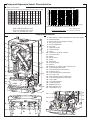
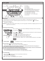
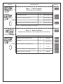
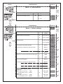
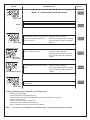
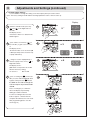
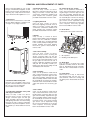
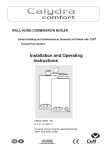
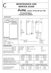
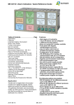
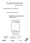
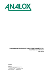
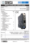
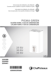
c
MAINTENANCE AND
SERVICE GUIDE
Fanned Flue Condensing Central
Heating System Boiler 24 and 30
Dimensions
Outer case dimensions :
440 (minimum space required 450)
- Width :
850
- Height :
- Depth :
380 (24kW) - 405 (30 kW)
360
360
50
50
212
212
67
67
737
850
737
850
235
232
L
NJ
32
24380
: 380
30 : 405
Flue types:
C 13: C 33: C 53:
I
J
L
N
Safety valve outlet
Heating flow
Gas supply
Heating return
Safety valve
center line
108 108 88
J
L
N
I
All dimensions in mm
Technical Data
24 kW
30 kW
Heat gross input C/H maxi ............................ 9.2-27.8 kW 10.4-31.6 kW
Heat output C/H 50°/30° maxi .......................
9-26 kW
10-30kW
Heat output C/H 80°/60° maxi .......................
8-24 kW
9-28 kW
80°C max
80°C max
C/H operating temperature............................
0.7 bar
0.7 bar
C/H circuit pressures Min operating ..............
C/H circuit pressures Max operating .............
2.5 bar
2.5 barr
3 bar
3 bar
Safety discharge ...........................................
Expansion vessel - Pre-charge pressure ......
0,7 bar
0.7 bar
Net capacity at 3 bar in liter...........................
5.44
5,44
Supply ...........................................................
230 v
230 v
Consumption .................................................
150 w
150 w
Protection ......................................................
IP 44
IP 44
Fuse F1/F2/F3/F4 ......................................... 2 A/1.25 A/0.315 A/0.250 A
24 v
24 v
External controls ...........................................
24 kW
30 kW
Natural gas G20
Gas rate C/H max ................... 2.64 m3/h
Gas rate C/H mini.................... 0.87 m3/h
Gas valve restrictor diameter .. without
3.01 m3/h
1 m3/h
without
Propane L.P.G G31
Gas rate C/H max. .................. 1.94 kg/h
Gas rate C/H mini.................... 0.64 kg/h
Gas valve restrictor diameter .. 4.40 mm
2.21 kg/h
0.73 kg/h
4.80 mm
Pump and Expansion Vessel Characteristics
Pump head available
Pf Pression
froid pourinitial
le circuit
chauffage
(en bar)
Centralàheating
pressure
when
cold (in bar)
Hauteur manométrique
mCE
6
2,0
Minimum
flow(robinets
rate (with
all heating thermostatic
valves closed)
Débit mini
thermostatiques
fermés)
1,9
1,8
1,7
5
GV
F
4
3
GVO
2
40°C
1,6
1,5
1,4
50°C
1,3
1,2
PV
F
60°C
70°C
1,1
PVO
1
0
100
200
300
400
500
600
700
800
900
1000
1100
1,0
0,9
0,8
0,7
l/h
80°C
C liter
20
40
60
80
100
120 140
160
180 200
220
240 260
Capacité
System capacity
chartmaximale de l'installation (en litres)
GV F= high speed by-pass closed
GVO = high speed by-pass open
PV F= low speed by-pass closed
PVO = low speed by-pass open
Note : The system initial pressure should be over the following value :
System static height (in metre) + 0.7 = Initial pressure (in bar)
10
Components Location
1.- Steel chassis complete with expansion vessel (not visible)
2.- Sealed chamber
3.- Burner and heat exchanger assembly
4.- Air / gas connection
5.- 24 V modulating fan
6.- Gas valve
7.- Ignition electrode
8.- Ionisation probe
9.- Ignitor
10.- Combustion products manifold
11.- 24 V transformer
12.- Siphon
13.- Electrical box
14.- Pump
15.- Shunt plate
16.- Pressure gauge
17.- Silencer
18.- Automatic air separator and automatic vent
19 - Central heating flowswitch
21.- Central heating control thermistor
23.- Overheat sensor
37.- Central heating flow isolating valve
39.- Gas service tap
41.- Central heating return isolating valve
43.- Central heating pressure relief valve
46.- User’s guide
47.- Connecting tails (x3)
48.- Condensate drain
49.- Adjustable by-pass
50.- Right hydraulic assy
51.- Left hydraulic assy
10
11
7
1
2
9
3
8
4
12
5
6
17
23
48
15
13
14
16
23
18
19
1
3
0
21
4
bar
50
51
46
47
49
37
39
41
43
2
FUNCTIONING
Control Panel
33
34
35
36
24.- Display
27.- Setting key
28.- Setting key
29.- Central Heating switch
30.- Green indicator – Central Heating mode ON
31.- Central Heating temperature reducing key
32.- Central Heating temperature increasing key
33.- Green indicator – Power ON
34.- Orange indicator - Burner ON
35.- Red indicator - Lock out / flame failure
36.- Reset key
32
31
29
30 24
27
28
Switching on
1. Check that pressure in central heating system is above 0.7 bar and below 1.5 bar with the pressure gauge 16.
2. Check that the gas service tap is opened at the gasmeter and main power is on. Green indicator
Power ON 33.
3. Open the gas tap 39 (fig.21).
The boiler is now ready to use.
Attention ! If the boiler stays a long time without working, some air in the gas pipe can hinder the first lightings. (please refer to paragraph 19 Incorrect Function)
Switching on Central heating
Press on key 29
, the green indicator 30 will light and the display will show the Heating
flow temperature.
Keys 31
and 32
allow to adjust the temperature required in the Central Heating system
regarding the weather conditions.
• press
to increase temperature when weather is cold
• press
to reduce temperature when weather is fair
During the temperature setting operation the display will flash.
If the room thermostat is calling for heat, a dot will be displayed at the bottom of the 3rd digit
Stand by mode
A fixed digit at the centre of the display and the green indicator 33 on
Putting the boiler in stand by mode and anti freeze system. :
Press on key 29
, to switch off CH mode. The green indicators 30 will stop.
During the all duration of the stand by mode, an automatic anti-sticking system will switch on the pump for 1
minute and make a movement of the 3 way valve each 23 hours.
The stand by mode will disable the anti-freeze function of the room thermostat (if fitted). To leave the room thermostat
anti freeze system operative, please let the Central Heating mode on.
The boiler is equipped with an automatic anti freeze system which permanently on.
If the Central Heating temperature decrease bellow 7°C, the pump will start.
If the Central Heating temperature decrease bellow 4°C, the pump and the burner will start.
Turn off the boiler
- Press on key 29
, to switch off CH mode. The green indicators 30 will stop
- Switch off the main electrical supply
- Shut off the gas service tap 39 (fig. 21)
Note : In this conditions, the anti-freeze system is inoperative
3
Central Heating Mode
To be able to supply heating, the mode should be switched ON. Press on key 29
, the green indicator 30 will light, and the
display will show the Heating Flow temperature.
Keys 31
and 32
allow to adjust the temperature required for Central Heating system regarding the weather conditions.
During the setting operation, the display will flash.
When there is a demand for heating, (either from the room thermostat or the clock) the pump starts. If the boiler temperature control
is calling for heat and the primary flow rate over 4 lt./min., the central heating flow switch operates, allowing the ignition sequence to
begin. The fan on the gas valve assembly starts and when the lighting speed is reached (detected by a hall effect sensor) the
2 safety solenoids open together to allow gas to the burner. The ignition sequence begins and a continuous high speed spark ignites
the gas. As soon as a flame is detected, the orange indicator led 34 will light and the regulation system will be able to adjust the gas
rate regarding the heat load. If a flame is not detected, after 10 seconds, the security solenoids close together and shut off the gas.
The red lockout indicator led 35 will light. Press the reset button to re-light the burner.
The central heating flow temperature is controlled by the central heating control thermistor 21. The boiler has been designed to
minimise cycling and will not attempt to re-light for at least 3 min. after the boiler thermostat has been satisfied. When the room
thermostat is satisfied , the burner will switch off and the pump will remain running for a further 3 minutes before it too stops.
Note
It is possible to override the 3 minute delay by pressing the Reset key 36
Lockout procedure
Flame disappearance :
When the ionisation electrode 8 does not detect flame presence. The orange indicator led 34 extinguishes. A lighting cycle starts. If
a flame is not detected, before 10 seconds, the safety solenoids will close. The lockout red indicator 35 lights and the display shows
the error code. The pump continues to run. After a few seconds, it will become possible to reset the boiler by pressing the reset
key 36.
Overheat detection :
If an overheat (over 100°C) is detected in the primary circuit by the sensor 23, the safety solenoids close and the fan stops. The
orange led 34 extinguishes and the pump remains running for 3 minutes. The reset will be possible when the primary temperature
will decrease under 76°C.
4
CENTORA GREEN FUNCTIONAL DIAGRAM
3
7
8
5
6
12
23
48
13
21
19 16 18
14
49
37
39
41
ELECTRICAL WIRING
DIAGRAM
5
43
ACTION
DISPLAY
CONFIGURATION
Menu - 1 - Default register
Record the last 10 defaults
5”
Section
x times
Digit 1
Digit 2 and 3
Last default occured
0•
code from 01 to 99
Last but one default occurred
1•
code from 01 to 99
...
...
code from 01 to 99
Last default occurred before the previous one
9•
code from 01 to 99
Note -- is displayed if no default is recorded.
Menu - 2 - Boiler conditions
Indicates the conditions or the configurations of the boiler
once
x times
Section
Digit 1
Digit 2 and 3
Software version of display PCB
0•
10 to 99
Flue type
2•
1 : FF
variable speed
Room thermostat is calling for heat
3•
0 : no
3•
1 : yes
CH flow temperature in Celsius degrees
7•
from 00 to 99
Software version of main PCB
9•
10 to 99
6
ACTION
DISPLAY
CONFIGURATION
once
Digit 1
Section
Under floor heating system
0
Factory
setting
Menu - 3 - Boiler options
Digit 2 and 3
0 : no
1 : yes
x times
DISPLAY
CONFIGURATION
Menu - 4 - Boiler settings
Section
Digit
1
Digit
2 and 3
0
0 : Burner only
0
1 : Burner and pump
1
0 : High speed
1
1 : Low speed
Pump post circulation duration
2
0.0 min
From 0 to 5 minutes by step of 0.5 min.
2
0.5 min
2
1.0 min
2
5.0 min
4
50°C
4
80°C
CH anti cycling delay
8
0.0 min
From 0 to 7 minutes by step of 0.5 min.
8
0.5 min
8
2.5 min
8
5.0 min
9
Value from
0 to 10
9
Value from
0 to 10
once
Room thermostat operation
x times
Pump speed
Maximum Central Heating flow temperature
CH maximum output limitation
Model 24
From step 0 (P. min.)
8 kW
to step 10 (P. max.) 24 kW
Model 30
From step 0 (P. min.)
9 kW
to step 10 (P. max.) 28 kW
7
Factory
setting
ACTION
ACTION
DISPLAY
CONFIGURATION
Menu - 5 - Combustion rate control mode
press once
Display
Effect
wait 5 ”
Combustion rate control mode OFF
Switching on the combustion rate
control mode. Central heating output
reach the maximum power set in
menu 4 section 9.
Central heating temperature is displayed in celsius degrees.
The 3 dots indicate that the combustion rate control is ON at maximum
output.
XX
Switching the combustion rate
down to minimum power.
Central heating temperature is displayed in celsius degrees.
The dot indicates that the combustion rate control is ON at minimum
output.
XX
press once
press once
press once
Switching on the combustion rate to Central heating temperature is dismaximum output set in menu 4 secplayed in celsius degrees.
tion 9.
The 3 dots indicate that the combustion rate control is ON at maximum
output.
Switching off the combustion rate
control mode.
press once
Locking conditions of the combustion rate control mode :
- boiler in stand by mode
- room thermostat is not calling for heat
- room thermostat is calling for heat but the maximum temperature is reached
- boiler in lockout mode
- after a reset or if the main supply fails
- end of the mode if operator leave menu 5
- after 15 minutes if there is no actions on keyboard
Nota :
As soon as the combustion rate control mode is on, Central Heating key is inactive.
8
XX
Adjustments and Settings (continued)
9
CH heat output setting :
If you would like to change the setting of C/H heat output, please proceed as follow :
(note : the factory setting is 18 kW and the following explanation refer to menu 4 section 9)
Display
1
1
- Switch to installer mode, press key
and
5”
on the Right side for 5
seconds.
The display shows :
-1- then 0•-- if there is no default in the
default register.
2
- press 3 times on menu key
(on
2
x3
the Left side ) to gain access to menu 4-,
The display shows :
-4- then the value set for section 0 ( 00
or
or 01 respectively Action on burner only
or pump and burner)
3
- change for section 9 (Adjustment of
CH heat output). Press on key
on
3
x9
Right side 9 times.
The display shows :
(906 which corresponds to the 18 kW
which is the factory setting)
9 = section 9
4
06 = 18 kW
- press on setting key
(on the Left
side) once, the 2nd and 3rd digits flash
4
together. Then press the
key on
the DHW or CH side to change the
C/H heat output steps between 00
and 10.
Press on setting key to confirm the
value. The display stops flashing.
Setting procedure is finished.
To exit from setting mode, leave the
boiler for approx. 1 minute then the
computer will switch back to user mode.
After programming please close the
door P (fig. 18)
9
REGULATION
FLOW SWITCHES
Temperature regulation for C/H circuit is controlled by 1 thermistor. The C/H
knob allows the adjustment of temperature between 35 and 85°C.
Resistance value are
- 5000 Ω at
- 2631 Ω at
- 620 Ω at
- 255 Ω at
25 °C
40°C
80°C
110°C
Flow in Heating circuit is detected by 1
flow switche. A piston with a magnet at
the top operates a REED switch. The
piston is lifted by flow rates listed below :
Flow rate threshold :
C/H 250 l/h ±20 l/h
ROUTINE SERVICING
To ensure continued efficient operation of the appliance, it is recommended that it is checked and serviced as necessary at regulars intervals. The frequency of servicing will depend upon the particular installation condition and usage, but in general, once
a year should be adequate.
It is the law that any service work must be carried out by a competent person such as your local Chaffoteaux Service Centre,
British Gas or other CORGI registered personnel in accordance with the current Gas Safety (Installation and Use) regulation.
Attention ! the air/gas connection pipe between the gas valve and the burner should never open. The seal can be checked only
in the factory.
The service schedule should include the following operations :
- Check the pressure in the system
- Check the correct operation of the appliance
- Check the correct operation of the gas controls
- Check the functions of safety controls
- Clean the electronic board of the fan located on the gas valve assembly and the different transformers in the sealed chamber.
- Check combustion chamber insulation panels for damage
- Check the lighting and ionisation electrodes condition
- Clean the burner (Never use metallic brush which can damage the stainless steel)
- Clean the heat exchanger (Never use metallic brush which can damage the stainless steel)
- Clean the siphon and pay attention to the acidity of its contents
- Check the correct seal of the drain system
- Clean gas and water filters
- Check expansion vessel charge pressure
- Clean an check operation of safety valve
- Check the correct seal of the flue system.
Additional procedures that may be necessary :
- Check the burner pressure and the gas flow rates
- Check, clean or replace components as necessary
- Carry out combustion test utilising the test points in the flue turret
Suggested sequence for servicing :
Before disconnecting or removing any part, isolate the gas and electricity supplies. Ensure that the appliance is cool, and take
care about the condensats products content in the siphon which are acid.
(For detail, please see section on Parts Removal and Replacement)
Preliminary checks
- Remove outer case
- Check the system pressure is at least 0.7 bar cold
- Check that the burner is extinguished fully when both solenoids are closed and fan is off.
- Test ionisation functions and check that lockout occurs by turning off gas tap.
- Whilst boiler is operating, check operation of the primary flow switch by closing heating flow valve and by pass screw (turn
clockwise ) noting the number of turns so that it may be reset correctly.
- Control the correct flood of condensats in the siphon which is transparent.
10
REMOVAL AND REPLACEMENT OF PARTS
Before removing appliance case, isolate
the gas and electrical supplies. Isolate
boiler from the system and drain before
removing any component in the waterways. Ensure that the appliance is cool.
1. Outer Case
Remove four screws in base of case and
lift free. When replacing, carefully locate
on lugs T on top edge of chassis.
4. Ionisation electrode
Carry out step 1 and 2 as above.
Disconnect ionisation electrode from its
wiring. Loosen the 2 screws and pull it
out from the combustion chamber front
panel. Replace the ionisation gasket
provided. Reassemble in reverse order
5. Lighting electrode
Carry out step 1 and 2 as above.
Disconnect lighting electrode from its
wiring. Loosen the 2 screws and pull it
out from the combustion chamber front
panel. Replace the ionisation gasket
provided. Reassemble in reverse order.
10. Venturi in the gas section
Carry out all operations mentioned in
step 7. Unscrew the three screws securing the air/gas connection pipe onto the
gas valve assembly. Separate the gas
valve assembly and the venturi from the
fan assembly by loosen the two hexagonal head screws. The venturi and the
gas section can be separated loosing
the 2 screw located at the top of the gas
valve. Replace necessary gaskets
before reassemble in reverse order.
11. Drain down
2 drain points are located on the boiler
.
1
A A
A
A
T
6. Burner
Carry out step 1, 2 and 3 as above.
Remove the 4 Philips screw retaining the
burner onto the combustion chamber.
Pull it out with care to avoid any damage
to the ceramic panel protecting the combustion chamber front panel. Replace
the burner gasket. Reassemble in
reverse order.
T
1
2
2. Sealed chamber front panel
Unscrew four self taping screws securing the sealed chamber front panel and
lift over top corner locating lugs.
Reassemble in reverse order.
3. Combustion Chamber front panel
and air/gas connection
Carry out step 1 and 2 as above.
Unscrew three screws securing the
air/gas connection pipe onto the gas
valve assembly. Disconnect Ionisation
and lighting electrodes from their wiring.
Unscrew six nuts to release combustion
chamber front panel and pull the assembly towards you. Reassemble in reverse
order.
7. Gas vale assembly
Carry out step 1 and 2 as above.
Unscrew three screws securing the
air/gas connection pipe onto the gas
valve assembly. Disconnect the connectors from gas solenoids and fan. Loosen
the gas pipe nut. Unscrew six nuts to
release combustion chamber front panel
and pull the assembly towards you.
Replace gas filter before fitting the full
assembly back in the boiler.
8. Fan assembly
Carry out all operations mentioned in
step 7. Unscrew the three screws securing the air/gas connection pipe onto the
gas valve assembly. Separate the gas
valve assembly and the venturi from the
fan assembly by loosen the two hexagonal head screws. Reassemble in reverse
order and replace the necessary gaskets.
9. Gas section
Carry out all operations mentioned in
step 7. Unscrew the three screws securing the air/gas connection pipe onto the
gas valve assembly. Separate the gas
valve assembly and the venturi from the
fan assembly by loosen the two hexagonal head screws. The venturi and the
gas section can be separated loosing
the 2 screw located at the top of the gas
valve. Replace necessary gaskets
before reassemble in reverse order.
11
2
1 = Air separator
2 = Heating circuit drain point
12. Water filter
The C/H filter is located in the right
hydraulic assembly. Remove the return
pipe as described previously and withdraw the filter. Reassemble in reverse
order.
13. Flow switch
Drain boiler as in step 11. Disconnect
the electrical plug, turn the top cover
anti-clockwise, remove the O-ring and
the brass piston. Reassemble in reverse
order.
16. Main heat exchanger
Carry out step 1 and 2 as above. Drain
down the boiler as in step 11. Unscrew
three screws securing the air/gas connection pipe onto the gas valve assembly. Disconnect Ionisation and lighting
electrodes from their wiring. Unscrew six
nuts to release combustion chamber
front panel and pull the assembly
towards you. Undo the two clips of the
pipes to the main exchanger and pull
down the pipes. Unscrew the three
screws located at the bottom, top left
and at the right with the retaining system
to be able to pull the main heat exchanger towards you.
Reassemble in reverse order taking care
about the location of the gasket on the
fumes collector and replace the necessary gaskets.
19. Thermistor
Drain the boiler as step 11. Disconnect
the plug, remove the retaining clip pull
the thermistor out. Reassemble in
reverse order.
21
21 = Heating thermistor
20. Safety thermostat
Remove the casing as step 1 and hinge
down the electrical box as step 5.
Disconnect the 2 cables, pull out the
sensor with the clip (23). Reassemble in
reverse order.
G
F
18. Pressure relief valve
The pressure relief valve can be serviced from the front of the appliance.
Drain the boiler first, undo the retaining
screw
and
pull
out
the
valve.Reassemble in reverse order.
24. Expansion vessel
Remove the casing as step 1 and drain
the boiler as step 12 above. Unscrew the
connecting tails nuts and lift out the boiler from the wall. Place it on a side on the
floor. Remove the expansion vessel
bracket retaining screws, disconnect the
pipe from the vessel and pull it toward
you. Reassemble in reverse order.
25. Pressure gauge
Carry out step 1 as above and drain the
boiler as step 12. Hinge down electrical
box by pressing the retaining tabs P on
either sides. Press on the clip to remove
it and pull it out. Remove the clip which
hold the connection of the capillary on
the pump hose. Hang out the pressure
gauge with its capillary. Reassemble in
reverse order.
23
17. Pump
Drain boiler as in step 11. Pivot the electical box downwards. Open the electrical
box cover removing the 2 screws.
Remove the pump plug from the power
board and earth plug from earth socket.
Unscrew the nut F of the return pipe
from the volute. Remove the clip G on
the pump volute and pull the pump
toward you. Reassemble in reverse
order.
23. Display PCB
Carry out step 1 as above and hinge
down electrical box by pressing the
retaining tabs P on either sides. Remove
the pressure gauge clip. Rotate the electrical box back in upper position. Undo
the 2 screws retaining the front panel,
put your two hands at the bottom of the
front panel and pull it down to release it
from the 2 clips. Hinge down again the
electrical box. Undo the 4 screws of the
electrical rear panel and remove it.
Unplug the display board cables from
the main PCB. Reassemble in reverse
order.
21. Spark generator
Carry out step 1 and 2 as above. Unplug
the connector from the spark generator
located on the right hand side of the
main heat exchanger. Loosen the two
screws to remove the igniter.
Reassemble in reverse order.
22. Main control board
Carry out step 1 as above and hinge
down electrical box by pressing the
retaining tabs P on either sides. Remove
wiring cover C. Undo the 4 screws of the
electrical rear panel and remove it.
Unplug all cables from the PCB, remove
earth plug from earth socket. Hang out
the main PCB. Reassemble in reverse
order.
P
P
C
12
13
Release pump rotor
Replace control PCB or
display PCB
No
- Check mains electrical
connection
- Check internal fuses
- Check connection between
the 2 PCBs
No
No
Ok
Yes
Yes
Replace control PCB
Replace pump
Ok
Check that the pump
spins freely
Ok
Check voltage in the
pump electrical box
Please refer to the list of error
codes and solve the problem
Press the reset button
Does the green LED
alight ?
Switch on the main electrical supply
No
Ok
No
Yes
Does the pump run ?
Switch heating ON
No
Does the display
show a - XX code ?
No
-11
Replace fan assembly
-12
Replace heating thermistor
-7
- Check heating flow switch
- Check the main heat exchanger.
They could be fully scaled.
Does the red LED
light ?
-7
Ok
Ok
No
No
Yes
Check the 24 V at the
transformer
No
Check voltage on the
fan
Ok
Check heating
thermistor
Ok
Ok
Check heating flow rate in
the circuit
No
Does the fan run ?
error code displayed
means a group of actions
means an action
means a test or a choice
FAULT FINDING CHART Part 1
No
Yes
Wait for 4 seconds
Replace transformer or the relevant fuse
-3
Replace spark generator or
ignition electrods assembly
-24
Yes
Yes
Replace control PCB
No
Does the spark
generator energize ?
No
Does the -24 error
display ?
No
Could you see the
spark generation?
Description
Overheating LockOut
No flame detection
Anti-frost mode on
Anti-frost mode on
No water circulation
Faulty water circulation in the primary circuit
Central heating thermistor faulty, Opened circuit
Central heating thermistor faulty, Short circuit
Ignition test
Faulty connexion
Low speed fan
Faulty control functionning fan
Error communication with EEPROM
Error communication with the main PCB
Wait for 1 minute if the error
code 24 still display.
- check the connection fan or
replace the fan
Error code
1
3
5
6
7
8
11
12
18
20
23
24
31
32
PLEASE CHECK THE FOLLOWING POINTS CAREFULLY BEFORE
GOING THROUGH THE FAULT FINDING CHART
-Gas pressure
-Electric mains
-Minimum water pressure in the heating circuit (over 0.8 bar)
-All isolating valves have been opened
-Boiler air vented
-Check that the heating filter is clear.
- Remove the front panel of the sealed chamber
Yes
14
Check that air inlet pipe, venturi, fan, air/gas pipe or burner
are free of dust and not blocked
Replace control PCB
No
No
Replace gas section assembly
Yes
Do you feel air drawing in at the air inlet ?
Yes
Do the gas
solenoïds energise ?
Purge the gas pipe and press
on reset button
No
Can you see the
flame on the burner ?
Yes
The heating outlet
pipe temperature rises
Yes
Does the orange
LED light ?
No
-3
Replace control PCB
Ok
Check ionisation
probe
No
Is the combution
chamber full of condensates ?
Yes
Does the red LED
light and -3 displayed ?
No
Does the burner still
alight ?
FAULT FINDING CHART Part 2
No
Yes
No
Yes
Replace control PCB
Replace the ionisation probe
Drain and clean combustion chamber, siphon and drain pipes
Replace display PCB or control the
connection between the 2 PCBs
Replace display PCB or control the
connection between the 2 PCBs
Yes
The boiler is OK
No
Does the orange
LED light ?
Wait until the return pipe
become hot then reduce CH
temperature to minimum
SHORT LIST
507
510
640
805
110
938
607
401
RL1A
P1
P2
P3
P4
D14
RL1
R9
R8
C25
D16
R30 C38
8
VD
M/A
1
C79
D1
R111
R116
D39
1
D36A
D42
R113
R108R107
C76U9
D41
R128
T11
C74
D36
R105
R129
D2
R106
C80
C75
D5
R7
R115
VITESSE
J3
RL8
D3
C77
RL9
R112
T12
C24
R119
R114
K Z4A
R110
R118
R3
Z5
K Z5A
R5
R117
U10
R122
R121
R4
T1
FT1A
FT1
Z4
C9
R120
R1
R2
C23
Z3
C10
C11
E
E-1
R29
R79
R11
R18
R12
R14
C21
R100
R22
R98 R99
R16
D43
D4
D38
D37
R47
TERR
D30
C81
D44
R130
RL10
+
C7
C5
R109
R26
R27
R20
C30
EXT
Z7A Z7
Z8A
R21
C6
C4
Z1
F2
F2A
C22
CTP1
R48
TA
C63
C62
R69
R68
R72
R74
C36
R132
P1
TR1
Z2
D11
TERR
R46
J2
R6
R24
D9
D7
D6
K
PROG
1
R131
T14
TH2
J8
1
RL12 J4
T13
C82
C8
D45
R34
D13
C12
F3
F3A
C13
R28
1
+
R73
R13
5
R38
R42
D18
C15 C16
C37
P2
R45
K
1
RL11
J5
T6
T6A
RAD1
R44
RL3A R49
C32
BUS
C53
C52
R43
KCD
R75
RL7
C14
230V
R70
R76
Z6A
Z6
C31
560
C67
C66
C65
C64
Z10
C44
R50
+
C34
R23
T10
+
D40
DL1
R71
+
R54
C83
RL7A
K
C41
C51
ST1
+
C42
D20
J9
+
1
1
ST2
REP
R102
C18
R25
C47
TH1
TH1A
RL3
R52
COM
R37
J6
D32
RL6
R55
T3
Z9
Z9A
C43
R127
TR
J7
D31
C46
+
D19
D26
C78
R15
+5V
R39
R77
R67
U3
D22
D23 C35
J10A
C29
C61
U5
R53
RL2A
R31
R19
R35
C56
C19
R92
D27
D28
R65
R66
C45
1
C54
U6
Z11A
Z11
R51
R13
C28
R93
C68
R87
R88
T4
R57
C48
C27
L1
C55
C26
C60
C20
C72
C71
R94
R95
D33
D24
Z10A
R64
R58
R59 R90
K
D29
C50
D21
C70
T7 C69
C49
R91
D25
T8
T5
RL5
RL5A
R62
RL4
RL4A
Q1
R89
407
U7
R10
C59
R78
D15
4
3
2
1
U4
C33
C17
D34
R97
R96
D17
N
R32
R33
SW1
0
T2
C39
D12
R101
R41
532
MOV1
J1
C3
C1
C2
F1A
615
572
627
628
629
Key N°
Description
G.C N° Manf. Pt. N°
Type
Ce
nto
ra
gre
en
sy
ste
m
630
Manf. date
from
FF
110
401
407
507
510
532
560
572
607
615
627
628
629
630
640
805
938
ELECTRODE KIT
GAS VALVE
(24 kW)
GAS VALVE
(30 kW)
FAN ASSY
OVERHEAT THERMOSTAT 100°C
THERMISTOR
WATER THROTTLE
AIR SEPARATOR HEAD ASSEMBLY
PUMP UP 15/50 230V
IGNITER
PRINTED CIRCUIT BOARD
FUSE 250V 2A - TEMPORIZED
FUSE 250V 1A - TEMPORIZED
FUSE 250V 1.25A - TEMPORIZED
FUSE 250V 0.315A - TEMPORIZED
TRANSFORMER
PRESSURE GAUGE
PRESSURE RELIEF VALVE
1309624
1307584
1310129
1307585
1010572
1000733
81471
1002653
1010612
1002105.20
1310357
1003456
1003634
1003635
1307845
1308149
1303158
1020933
.
.
.
.
.
.
.
.
.
.
.
.
.
.
.
.
.
.
15
to
This appliance is suitable for Natural gas or LPG. A gas conversion must be made by a competent person.
Manufacturer:
Chaffoteaux & Maury - France
Commercial subsidiary:
MTS (GB) Limited
MTS Building
Hughenden Avenue
High Wycombe
Bucks HP13 5FT
Telephone:
Fax:
Internet:
E-mail:
(01494) 755600
(01494) 459775
www.chaffoteaux.co.uk
[email protected]
Technical Support Help Line:
Customer Service Help Desk:
0870 241 8180
0870 600 9888
1310558d - 12/2002
Chaffoteaux & Maury are continuously improving their products and therefore reserve the right to change specifications without prior
notice and accepts no liability for any errors or omission in the information contained in this document.