1
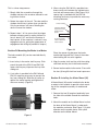
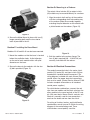
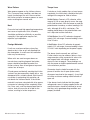
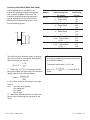
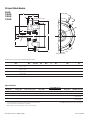
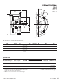
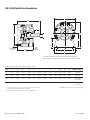
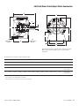
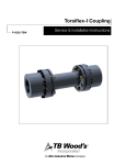
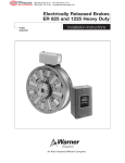
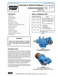
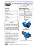
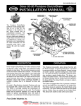
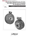
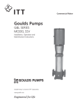
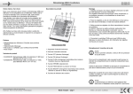
Electro-Module EM-50,
EM-100, EM-180, EM-210, EM-215
Service & Installation Instructions
P-213-WE
819-0303
An Altra Industrial Motion Company
Contents
Pre-Installation Instructions
Pre-Installation Instructions . . . . . . . . . . . . . . . .2
Installation Instructions . . . . . . . . . . . . . . . . . . .4
Setting Airgap . . . . . . . . . . . . . . . . . . . . . . . . . .5
Electrical Coil Data . . . . . . . . . . . . . . . . . . . . . .8
Burnishing . . . . . . . . . . . . . . . . . . . . . . . . . . . . .9
Troubleshooting . . . . . . . . . . . . . . . . . . . . . . . . .9
Maintenance . . . . . . . . . . . . . . . . . . . . . . . . . . .9
Overhung Load Data . . . . . . . . . . . . . . . . . . . .11
Dimensions and Specifications
EM-50-10 . . . . . . . . . . . . . . . . . . . . . . . . . .12
EM-100-10 . . . . . . . . . . . . . . . . . . . . . . . . .12
EM-180-10 . . . . . . . . . . . . . . . . . . . . . . . . .12
EM-210-10 . . . . . . . . . . . . . . . . . . . . . . . . .12
EM-50-20 . . . . . . . . . . . . . . . . . . . . . . . . . .13
EM-100-20 . . . . . . . . . . . . . . . . . . . . . . . . .13
EM-180-20 . . . . . . . . . . . . . . . . . . . . . . . . .13
EM-210-20 . . . . . . . . . . . . . . . . . . . . . . . . .13
EM-215-20 . . . . . . . . . . . . . . . . . . . . . . . . .13
EM-50-30 . . . . . . . . . . . . . . . . . . . . . . . . . .14
EM-100-30 . . . . . . . . . . . . . . . . . . . . . . . . .14
EM-180-30 . . . . . . . . . . . . . . . . . . . . . . . . .14
EM-210-30 . . . . . . . . . . . . . . . . . . . . . . . . .14
EM-50-40 . . . . . . . . . . . . . . . . . . . . . . . . . .15
EM-100-40 . . . . . . . . . . . . . . . . . . . . . . . . .15
EM-180-40 . . . . . . . . . . . . . . . . . . . . . . . . .15
EM-210-40 . . . . . . . . . . . . . . . . . . . . . . . . .15
EM-10-20 . . . . . . . . . . . . . . . . . . . . . . . . . .16
EM-10-40 . . . . . . . . . . . . . . . . . . . . . . . . . .17
EM-20-30 . . . . . . . . . . . . . . . . . . . . . . . . . .18
EM-30-40 . . . . . . . . . . . . . . . . . . . . . . . . .19
NEMA Frame Standards . . . . . . . . . . . . . .20
Warranty . . . . . . . . . . . . . . . . . . . .Back Page
A. Before installing the Electro-Module to a
motor or reducer, make certain that the EM
size and NEMA frame dimensions match
according to Table 1.
EM
Size
50
100
180
210
215
Corresponding
NEMA
Frame Sizes
48Y/56C
48Y/56C
143TC/145TC
182TC/213TC
213TC/215TC
Shaft
Dia.
5/8
5/8
7/8
1-1/8
1-3/8
C-Face
Pilot Dia.
4-1/2
4-1/2
4-1/2
8-1/2
8 1/2
Table 1
B. Check the motor for shaft endplay. If the
shaft can be moved axially .030” or more, the
module should not be installed since excessive thrust may occur between the rotor and
field. The motor should not be used unless
the endplay can be reduced.
C. Install your specific modular combination
according to the installation steps specified
in Table 2. Use only those steps indicated for
each combination.
Failure to follow these instructions may result in product damage, equipment
damage, serious or fatal injury to personnel.
2
Warner Electric • 800-825-9050
P-213 • 819-0303
For these EM combinations:
Use sections:
Electro Module Clutch-Brake Between
C-Face Motor and Reducer – 10-20
A, B, C, G, H, I
Electro Module Clutch Between
Motor and Reducer – 10-40
A, B, C, G, H, I
Electro Module Clutch Brake – 20-30
B, C, G, H, I
Electro Module Clutch – 30-40
B, C, G, H, I
Electro Module Brake
on C-Face Motor – 20
D, C, G, H, I
Motor Mount Electro Module
Clutch-Brake on C-Face Motor – 20-M
C, E, H, I
Motor Mount Electro Module ClutchBrake on C-Face Motor – 10-20-M
A, B, C, E, H, I
Motor Mount Electro Module Clutch
on C-Face Motor – 10-40-M
A, B, C, E, H, I
Base-Mounted
Electro Module Clutch-Brake – 20-30-B
B, C, F, H, I
Base-Mounted
Electro Module Clutch – 30-40-B
B, C, F, H, I
Table 2
Warner Electric • 800-825-9050
P-213 • 819-0303
3
Installation Instructions
Section A: Mounting the Motor Clutch Module
(10 Module)
1. Examine the clutch adapter. Note that there
are gaps between the housing fins on roughly
half of the circumference of the unit. Mount
the clutch adapter with the open gaps down.
This will keep contaminants from falling into
the unit. There are four screws and washers.
These will be bolted through the adapter onto
the four holes in the face of the motor (See
Figure 1).
3. Slide the rotor onto the motor shaft. (See
Figure 3) Make sure the rotor hub slides
easily onto the shaft. If the fit is too tight,
polish the shaft with emery paper so the hub
will slide on easily. Do not use a hammer or
force the rotor hub onto the shaft. Slide the
rotor back off the shaft.
Figure 3
Figure 1
2. Look at the back side of the rotor and note
there are cardboard spacer buttons as
depicted in figure 2.
4. Insert key onto the shaft. Prick punch the
motor shaft keyway at the end of the key to
prevent the key from sliding out. Slide the
rotor onto the motor shaft until it bottoms
against the field.
5. Using an Allen Wrench securely tighten the
two setscrews in the rotor hub. (See Figure 4)
When the motor is turned on, the spacer buttons will quickly wear away and provide the
proper gap between the field and rotor. The
setscrews are accessible from the front of the
rotor on sizes 100, 180, 210, and from behind
the rotor on size 50 units.
Figure 2
Figure 4
4
Warner Electric • 800-825-9050
P-213 • 819-0303
Section B: Bolting Two Modules Together
The brake module (20) and/or output clutch
module (40) may be assembled to the mounted
motor clutch module (10) or the input clutch (30).
1. Position the modules so that, in the usual
horizontal position, the ventilation holes are
down to prevent foreign matter from falling
into the units.
2. Bolt the modules together with the long hex
head bolts that are provided, see figure 5.
Mating pilot diameters assure proper alignment between module assemblies.
Figure 6
3. Proceed to Section C
Figure 7
Figure 5
If the armature for either the clutch or the brake
is too far away from its mating friction surface, it
is possible to move this back into adjustment
using a flat blade screwdriver between the two
armatures. See figure 8.
Section C: Adjusting Airgap
For new installations it is necessary to adjust the
airgap between the friction faces of the clutch
and/or brake.
To set the airgap for an Electro-Module (EM) you
will need to access the armatures. On an EM
there are gaps between the fins on the housing
on 1/2 of the unit circumference. When looking
through this gap, you will see the fan on the
clutch rotor. In that fan there is a 1/2 x 1 inch
window. It is possible to look inside the unit and
see the armatures by looking through this window. When looking through this window you will
be looking between the two armatures of a
clutch/brake unit as shown in figures 6 and 7.
Warner Electric • 800-825-9050
Figure 8
P-213 • 819-0303
5
This is a three step process.
1. Simply slide the screwdriver through the
window and press the armature toward its mating friction surface.
2. Rotate the output of the unit. The rotor and the
window should stay in place when you do this.
Only the armatures will move. Rotating the
rotor will move the window.
3. Repeat steps 1 & 2 to ensure that the airgap
between armature and its mating friction surface is about 1/32” and that the armature is
kept square. (If the armature is cocked, it may
engage on one rim, giving the appearance of
engagement but failing to provide full torque.)
Section D: Mounting the Brake to a Motor
The brake module (20) can be mounted directly
to a motor.
1. Insert a key in the motor shaft keyway. Prick
punch the end of the (EM-50 and EM-100)
motor shaft keyway to prevent the key from
sliding out.
2. A set collar is provided in the EM-180 and
EM-210 mounting accessory to prevent the
key from sliding out. Slide the set collar up
against the motor bearing and tighten the
setscrew securely. (Figure 9)
3. When using the EM-180-20 a possible interference may exist between the splined armature hub and some motors. (See Figure 10) A
spacer ring is provided with the EM-180
mounting accessory to provide the necessary
running clearance.
C-face mounting
If this boss extends
beyond the C-face
surface use the
spacer.
Do not use spacer
if boss is below the
C-face surface.
Figure 10
Place the spacer ring between the brake
module housing and the C-face of the motor
when bolting the two units together.
4. Align the motor shaft and key with the mating
shaft hole and key slot in the brake module.
5. Secure brake module to the motor C-face with
the four (4) long 3/8-inch hex head capscrews.
Section E: Installing the Motor Mount (M)
A Motor Mount (M) can be installed to the brake
or output clutch module to provide a foot mounting for the complete assembly of module and
motor.
1. Remove the two (2) long hex head bolts from
the side of the module toward the ventilation
holes.
2. Mount the module on the Motor Mount so that
the base of the Motor Mount is underneath
the modules and motor. (See Figure 11) A pilot
diameter on the module mates with a pilot
diameter on the Motor Mount.
Figure 9
6
Warner Electric • 800-825-9050
P-213 • 819-0303
Section G: Mounting to a Reducer
The output side of a brake (20) or output clutch
(40) module may be mounted directly to a reducer.
1. Align the output shaft and key of the modules
with the corresponding shaft hole and keyway
of the reducer. Slide the assembly together,
matching the pilot diameter on the module with
a pilot diameter on the reducer. (Figure 13)
Figure 11
3. Secure the Motor Mount in place with two (2)
longer mounting bolts and the two shorter
bolts all provided in the kit.
Section F: Installing the Base Mount
Modules 20-30 and 30-40 can be base-mounted.
Figure 13
1. Mount the modules so that the base is located
below the ventilation holes. A pilot diameter
on the end of each module mates with pilot
diameters on the base.
2. Bolt the module to the reducer flange. The
four (4) bolts required (3/8 - 16 UNC-2A) are
normally furnished with the reducer.
2. Secure the base to the modules with the four
(4) bolts provided. (Figure 12)
Section H: Electrical Connections
The conduit connection hole in the motor clutch
module (10), brake (20), and input clutch (30) are
threaded for standard conduit connectors. The
wiring diagram, included with each Warner Electric
control shows the proper electrical connections
that must be made. (Control Service Manual P-239
includes complete information on all standard
control power supplies.)
Figure 12
For clutch/brake combinations, connect the red
wire from one module and the black wire from the
other module to the same terminal of the DC supply. With most basic Warner Electric controls, one
terminal is normally used for two connections –
one from the brake and one from the clutch.
For wiring of clutches, brakes, and clutch/brake
combinations consult manual P-239 for the wiring
diagram of the control being used. These
clutch/brakes are not polarity sensitive.
Warner Electric • 800-825-9050
P-213 • 819-0303
7
Electrical Coil Data
EM - 50 - 100 - 180 - 210 - 215
Voltage – D.C.
90
24
Clutch
Brake
Clutch
Brake
Clutch
Brake
Resistance
EM-50
452
452
1.86
1.86
31.8
31.8
@ 20˚ C - 0hms
EM-100
392
392
1.8
1.8
26.7
26.7
EM-180
392
392
1.8
1.8
26.7
26.7
EM-210
248
248
1.22
1.22
17.9
17.9
EM-215
Amperes
248
EM-50
.199
.199
3.23
3.23
.755
.755
EM-100
.23
.23
3.31
3.31
.896
.896
EM-180
.23
.23
3.31
3.31
.896
.896
EM-210
.363
.363
4.9
4.9
1.34
1.34
EM-215
Watts
.363
EM-50
18
18
19
19
18
18
EM-100
21
21
20
20
21.5
21.5
EM-180
21
21
20
20
21.5
21.5
EM-210
33
33
30
30
32
32
EM-215
Build-up – milliseconds
33
EM-50
52
53
52
53
52
53
EM-100
72
75
72
70
72
75
EM-180
72
75
72
70
72
75
EM-210
120
100
110
100
120
100
EM-215
Decay – milliseconds
Warner Electric • 800-825-9050
100
EM-50
6.2
5.0
6.5
5.0
6.2
5.0
EM-100
12
10
12
10
12
10
EM-180
12
10
12
10
12
10
EM-210
20
10
20
10
20
10
EM-215
8
6
10
P-213 • 819-0303
Section I: Burnishing
Intimate metal to metal contact is essential
between the armature and the metal rings (poles)
of the magnet or rotor. Warner Electric clutches
and brakes leave the factory with the friction
material slightly undercut to assure good initial
contact.
Normally, the desired wearing-in process occurs
naturally as the surfaces slip upon engagement.
The time for wear-in, which is necessary to
obtain the ultimate torque of the unit, will vary
depending on speed, load, and duty cycle.
If maximum torque is required immediately after
installation, the unit should be burnished by slipping the friction surfaces together at reduced
voltage. It is recommended that the burnishing
be done right on the application, if at all possible.
A. Visually inspect to ensure that the lead wires
are not split or cut.
B. Using a voltmeter confirms that DC voltage is
reaching the lead wires when it should be
and that the coil resistance is correct.
Mechanical - A likely mechanical cause for a
clutch or brake not engaging when DC power is
applied is that the airgap between the friction
faces is too large. When power is applied to an
Electro-magnetic clutch/brake, the unit magnetically clamps the friction faces together. An airgap that is too large can keep the unit from
clamping together. If the airgap is too small the
faces will rub all of the time.
To adjust the airgap, see Section C on page 5.
Maintenance
Burnishing at high speed will result in a smoother
wear-in pattern and reduce the time for burnishing. The voltage should be set at approximately
30% or 40% of the rated value.
The unit should be cycled on and off to allow
sufficient time between slip cycles to prevent
overheating.
When a Warner Electric brake or clutch is
properly assembled and installed, no further
servicing, lubrication, or maintenance should
be required throughout the life of the unit.
Troubleshooting
As with any friction-type device, some initial
concern should be given to wear rate, as minor
adjustments in actuation time can sometimes
extend the life of the unit.
For clutch modules, the control potentiometer
should be set high to reduce the actuation time.
For brakes, the setting can be reduced to
extend the braking time and thereby extend the
life. Once the best actuation time has been
established, precautions should be taken to prevent machine operators, or other personnel not
familiar with wear characteristics, from changing
the potentiometer setting arbitrarily for affecting
minor operating changes.
If an Electro-Module fails to engage, there are
several possible causes. These can be broken
down into two sub-headings: Electrical and
Mechanical.
Electrical - If a clutch or brake or clutch/brake
will not engage, review the wiring, switching and
connections.
Warner Electric • 800-825-9050
P-213 • 819-0303
9
Wear Pattern
Torque Loss
Wear grooves appear on the friction surfaces.
This is a normal wear condition, and does not
impair functioning of the unit. Never machine
the friction surfaces to remove grooves or score
marks resulting from normal wear.
If a brake or clutch module slips or loses torque
completely, the initial check should be the input
voltage to the magnet or field as follows:
Heat
Excessive heat and high operating temperatures
are causes of rapid wear. Units, therefore,
should be ventilated as efficiently as possible,
especially if the application requires fast,
repetitive cycle operation.
Foreign Materials
If units are used on machinery where fine,
abrasive dust, chips or grit are dispelled into
the atmosphere, a screen over the ventilation
holes may be necessary.
Where units are used near gear boxes or
transmissions requiring frequent lubrication,
means should be provided to protect the
friction surfaces from oil and grease to prevent
serious loss of torque.
Oil and grease accidentally reaching the friction
surfaces may be removed by wiping with a rag
dampened with a suitable cleaner, which leaves
no residue. In performing this operation, do
not drench the friction material. If the friction
materials have been saturated with oil or grease,
no amount of cleaning will be completely effective. Once such a unit has been placed back in
service, heat will cause the oil to boil to the
surface, resulting in further torque loss.
10
Warner Electric • 800-825-9050
90-Volt Series: Connect a DC voltmeter with a
range of 0-100 or more directly across the magnet or field terminals. With the power on and the
potentiometer turned up, a normal reading is 90
volts, although 85 to 95 is satisfactory. The
reading should drop as the potentiometer control is adjusted counter-clockwise.
24 Volt Series: Use a DC voltmeter of approximately 0-40 volt range. A normal reading is from
23 to 25 volts.
6-Volt Series: Use a DC voltmeter of approximately 0-15 volt range. A normal reading is from
5.5 to 6.5 volts depending on the power supply.
The above checks normally are sufficient.
Further checks may be made as follows: a low
range ammeter, when connected in series with
one magnet lead, will indicate amperes as
shown in chart on page 8. These readings are
with the power on and the potentiometer control
in the maximum position.
Ohmmeter checks should be made with the
power off and the circuit open (to be certain,
disconnect one lead to the magnet). A very high
or infinite resistance reading would indicate an
open coil.
If the above checks indicate that the proper
voltage and current is being supplied to the coil
mechanical parts should be checked to assure
that they are in good operating condition and
properly installed.
P-213 • 819-0303
Overhung Load Data (Shaft Side Load)
Overhung load data is provided in this
manual for the design engineer concerned
with a specific problem in this area. The
maximum allowable overhung load which
can be applied to the shaft of an ElectroModule may be determined by the use of
the accompanying chart.
A
R
The minimum pitch diameter pulley or sprocket
that can be used, for satisfactory bearing life, is
determined from the formula:
2TK
Min. P. D. = ––––––
R
T - Torque, (lbs. in.). This is the torque actually
being transmitted, not necessarily the maximum
torque capacity of the Electro-Module.
ElectroModule
Distance Load Applied
from Housing Face
“A” Inches
EM-50
1" - Center of Shaft
2" - End of Shaft
3"
EM-100
1" - Center of Shaft
2" - End of Shaft
3"
EM-180
1" - Center of Shaft
2" - End of Shaft
3"
EM-210
1-3/8" - Center of Shaft
2-3/4" - End of Shaft
4-1/8"
EM-215
1-3/8" - Center of Shaft
2-3/4" - End of Shaft
4-1/8"
Based on B10 Life at 3600 RPM
Maximum
Load Rating
“R” Lbs.
177
123
95
192
134
104
192
134
104
386
271
208
386
271
208
Example: What is the minimum V-belt pulley
that can be applied to the center of the shaft
of an EM-50 module?
The torque requirement is 112 in. lbs.
2 x 112 x 2
Min. P. D. = –––––––––– = 2" minimum P. D.
224
pulley
63025 x HP
Torque = –––––––––––
RPM
K - the safety factor for the tension in the type
of drive.
Use: 1 for chain and sprocket
1 for timing belt
2 for V-belt
3 for flat belt
R - Radial load allowable (values at various distances from the housing face are given in the
chart).
Warner Electric • 800-825-9050
P-213 • 819-0303
11
10 Motor Clutch Module
50-10
100-10
180-10
E
F
210-10
AA
1/2" NPT
BB
DD
D
B
A
1/2" NPT
CC
Electrical
Connection
C
Typical End View
All dimensions are nominal, unless otherwise noted.
Size
A Pilot Dia.
B Dia.
C
D Dia.
E Max.
F Max.
AA
BB Min.
CC
DD Key
50
4.500
.625
.813
6.750
.599
1.563
30°
36
45°
3/16 x 3/16
100
4.500
.625
.813
6.750
.599
1.563
30°
36
45°
3/16 x 3/16
180
4.500
.875
.813
6.750
.599
1.563
30°
36
45°
3/16 x 3/16
210
8.500
1.125
.703
9.250
.625
1.313
25°
36
45°
1/4 x 1/4
Specifications
Model Size
Voltage DC
Static Torque (lb. ft.)
Max. RPM
Inertia–WR2 (lb.ft.2)
Weight (lbs)
NEMA Frame Size
50
100
180
6, 24, 90
6, 24, 90
6, 24, 90
16
30
30
3600
3600
3600
.020
.046
.046
3.4
5.1
5.1
210
6, 24, 90
95
3600
.188
9.1
56C/48Y*
56C/48Y**
182C/143TC
184C/145TC
213C/182TC
215C/184TC
*
For 56C/48Y Frame motors 3/4 HP and smaller the EM-100 size
may be used where extended life is desirable.
** EM-100 size is recommended for motors 1 HP and larger.
12
Warner Electric • 800-825-9050
For NEMA Standard frame sizes, see page 20.
P-213 • 819-0303
AA
A
B
Electrical
Connection
C
D
20 Brake Module
50-20
100-20
180-20
210-20
215-20
E
1/2" NPT
BB
F
DD
J
I
H
L
See Note A
G
K
See
Note B
Notes:
A. Same overall dimensions apply
to Motor Brakes. 20MB Module
does not have an output shaft.
B. Clutch armature only applies
to EM-20.
CC
Typical End View
All dimensions are nominal, unless otherwise noted.
Size
50
A
Max.
5.188
B
3.125
C
D
E
Max.
Max.
.500 1.000 .156
100
5.188
3.125
.500
1.000
.156
180
5.266
3.125
.500
1.000
.156
210
7.578
4.609
.594
1.500
.313
215
8.078
4.609
.594
1.500
.313
F
3/8-16 UNC-2A
Equally Spaced
(4) on 5.875 D.
3/8-16 UNC-2A
Equally Spaced
(4) on 5.875 D.
3/8-16 UNC-2A
Equally Spaced
(4) on 5.875 D.
1/2-16 UNC-2A
Equally Spaced
(4) on 7.250 D.
1/2-16 UNC-2A
Equally Spaced
(4) on 7.250 D.
G
Dia.
6.688
6.688
6.688
9.344
9.344
H
I
J
K
L
Dia. Keyway Min. Pilot Dia. Dia.
.625 3/16 X 1.813 4.500 .625
3/16 x
1-3/8
.625 3/16 X 1.813 4.500 .625
3/16 x
1-3/8
.875 3/16 X 1.891 4.500 .875
3/16 x
1-3/8
1.125 1/4 X 2.500 8.500 1.125
1/4 x
2
1.375 1/4 X 3.000 8.500 1.375
1/4 x
2
AA
30°
BB
Min.
36
DD
CC
Key
45° 3/16 x 3/16
30°
36
45° 3/16 x 3/16
30°
36
45° 3/16 x 3/16
25°
36
45°
25°
36
45° 5/16 x 5/16
1/4 x 1/4
Specifications
Model Size Voltage DC
50
6, 24, 90
100
6, 24, 90
180
6, 24, 90
Static Torque (lb. ft.)
16
30
30
Max. RPM
3600
3600
3600
Armatures
.014
.036
.036
Inertia–WR2 (lb.ft.2)
Arm. Hub
Shaft
.002
.001
.003
.002
.003
.002
Weight (lbs)
6.6
8.1
8.1
210
6, 24, 90
95
3600
.162
.021
.017
21.5
215
90
95
3600
.162
.021
.019
22
*
For 56C/48Y Frame motors 3/4 HP and smaller the EM-100 size
may be used where extended life is desirable.
** EM-100 size is recommended for motors 1 HP and larger.
*** For 7-1/2 HP max.
Warner Electric • 800-825-9050
NEMA Frame Size
56C/48Y*
56C/48Y**
182C/143TC
184C/145TC
213C/182TC
215C/184TC
213TC/215TC***
For NEMA standard frame sizes, see page 20.
P-213 • 819-0303
13
30 Input Clutch Module
50-30
100-30
180-30
210-30
G
B
A
H
AA
1/2" NPT
Electrical Connection
BB
DD
D
I
F
E
C
CC
Typical End View
All dimensions are nominal, unless otherwise noted.
Size
A
50
1.000
B
Max.
1.56
100
1.000
1.56
180
1.000
1.56
210
1.500
.312
C
3/16 x
3/16 x 1-3/8
3/16 x
3/16 x 1-3/8
3/16 x
3/16 x 1-3/8
1/4 x 1/4
D
Min.
1.813
E
Pilot Dia.
4.500
F
Dia.
.625
G
Max.
4.328
H
2.266
I
Dia.
6.688
1.813
4.500
.625
4.328
2.266
1.891
4.500
.875
4.391
2.500
8.500
1.125
5.391
AA
30°
BB
Min.
36
CC
45°
DD`
Key
3/16 x 3/16
6.688
30°
36
45°
3/16 x 3/16
2.266
6.688
30°
36
45°
3/16 x 3/16
2.438
9.219
25°
36
45°
1/4 x 1/4
Specifications
Model Size
50
100
180
210
Voltage DC
6, 24, 90
6, 24, 90
6, 24, 90
Static Torque (lb. ft.)
16
30
30
Max. RPM
3600
3600
3600
6, 24, 90
95
3600
*
For 56C/48Y Frame motors 3/4 HP and smaller the EM-100 size
may be used where extended life is desirable.
** EM-100 size is recommended for motors 1 HP and larger.
14
Warner Electric • 800-825-9050
Inertia–WR2 (lb. ft.)
Rotor
Shaft
.020
.001
.046
.002
.046
.002
.188
.017
Weight (lbs)
6.4
8.4
8.4
19.8
NEMA Frame Size
56C/48Y*
56C/48Y**
182C/143TC
184C/145TC
213C/182TC
215C/184TC
For NEMA standard frame sizes, see page 20.
P-213 • 819-0303
40 Output Clutch Module
50-40
100-40
AA
180-40
210-40
1/2" NPT
A
B
C
BB
DD
F
D
H
E
G
CC
Typical End View
All dimensions are nominal, unless otherwise noted.
Size
50
A
Max.
5.188
100
B
3.125
C
Max.
.156
D
Dia.
6.687
5.188
3.125
.156
6.687
180
5.266
3.125
.313
6.687
210
7.578
4.609
.313
9.344
E
3/16 x
3/16 x 1-3/8
3/16 x
3/16 x 1-3/8
3/16 x
3/16 x 1-3/8
1/4 x
1/4 x 2
F
Min.
1.813
G
Pilot Dia.
4.500
H
Dia.
.625
1.813
4.500
1.891
2.500
AA
30°
BB
Min.
36
CC
45°
DD
Key
3/16 x 3/16
.625
30°
36
45°
3/16 x 3/16
4.500
.875
30°
36
45°
3/16 x 3/16
8.500
1.125
25°
36
45°
1/4 x 1/4
Specifications
Model Size Voltage DC
50
6, 24, 90
100
6, 24, 90
180
6, 24, 90
210
Static Torque lb. ft.
16
30
30
Max. RPM
3600
3600
3600
Armatures
.007
.018
.018
95
3600
.181
6, 24, 90
*
For 56C/48Y Frame motors 3/4 HP and smaller the EM-100 size
may be used where extended life is desirable.
** EM-100 size is recommended for motors 1 HP and larger.
Warner Electric • 800-825-9050
Inertia–WR2 (lb. ft.)
Arm. Hub
Shaft
.002
.001
.003
.002
.003
.002
.021
.017
Weight (lbs)
4.9
5.2
5.2
15.2
NEMA Frame Size
56C/48Y*
56C/48Y**
182C/143TC
184C/145TC
213C/182TC
215C/184TC
For NEMA standard frame sizes, see page 20.
P-213 • 819-0303
15
EM-10/20 Clutch/Brake Combination
I
A
C
D
K
E
J
L
10
Motor Clutch
Module
20
Brake
Module
B
N
O
N
M
Note: Mounting base is optional and is ordered separately.
Motor Clutch (10) and Output Clutch (20) are ordered separately.
All dimensions are nominal, unless otherwise noted.
Size
A
B
C
D
E
I
J
K
L
M
N
O
NEMA Frame Size
50
6.750
4.844
1.813
6.750
.625
6.688
3.500
6.844
2.000
6.000
.500
5.000
56C/48Y*
100
6.750
4.844
1.813
6.750
.625
6.688
3.500
6.844
2.000
6.000
.500
5.000
56C/48Y**
180
6.828
4.844
1.891
6.750
.875
6.688
4.500
7.844
3.000
6.625
.813
5.000
182C/143TC
184C/145TC
210
8.891
5.922
2.500
9.250
1.125
9.688
5.250
9.906
3.375
9.000
.625
7.750
213C/182TC
215C/184TC
*
For 56C/48Y Frame motors 3/4 HP and smaller the EM-100 size
may be used where extended life is desirable.
** EM-100 size is recommended for motors 1 HP and larger.
16
Warner Electric • 800-825-9050
For NEMA standard frame sizes, see page 20.
P-213 • 819-0303
EM-10/40 Motor Clutch/Output Clutch Combination
A
I
C
D
E
K
J
L
10
Motor Clutch
Module
40
Output Clutch
Module
B
N
O
N
M
Note: Mounting base is optional and is ordered separately.
Motor Clutch (10) and Output Clutch (40) are ordered
separately.
All dimensions are nominal, unless otherwise noted.
Size
A
B
C
D
E
I
J
K
L
M
N
O
NEMA Frame Size
50
6.750
4.844
1.813
6.750
.625
6.688
3.500
6.844
2.000
6.000
.500
5.000
56C/48Y*
100
6.750
4.844
1.813
6.750
.625
6.688
3.500
6.844
2.000
6.000
.500
5.000
56C/48Y**
180
6.828
4.844
1.891
6.750
.875
6.688
4.500
7.844
3.000
6.625
.813
5.000
182C/143TC
184C/145TC
210
8.891
5.922
2.500
9.250
1.125
9.688
5.250
9.906
3.375
9.000
.625
7.750
213C/182TC
215C/184TC
*
For 56C/48Y Frame motors 3/4 HP and smaller the EM-100 size
may be used where extended life is desirable.
** EM-100 size is recommended for motors 1 HP and larger.
Warner Electric • 800-825-9050
For NEMA standard frame sizes, see page 20.
P-213 • 819-0303
17
EM-20/30 Brake/Input Clutch Combination
EM-20/30-B Brake/Input Clutch Combination – Base Mounted
B
I
A
C
C
D
D
30
Input Clutch
Module
K
20
Brake
Module
H
F
G
E
L
H
F
J
N
O
N
M
Note: Mounting base is optional and is ordered separately.
Input Clutch (30) module and Brake Module (20) are
ordered separately.
All dimensions are nominal, unless otherwise noted.
Size
A
B
C Min.
D
E
F
G
H
I
J
K
L
M
N
O
50
5.719
9.516
1.813
.625
5.672
.844
4.000
.344
6.688
3.500
6.844
2.000
6.000
.500
5.000
100
5.719
9.516
1.813
.625
5.672
.844
4.000
.344
6.688
3.500
6.844
2.000
6.000
.500
5.000
180
5.719
9.656
1.891
.875
5.672
.844
4.000
.344
6.688
4.500
7.844
3.000
6.625
.813
5.000
210
7.719
12.969
2.500
1.125
8.203
1.094
6.000
.438
9.688
5.250
9.906
3.375
9.000
.625
7.750
18
Warner Electric • 800-825-9050
P-213 • 819-0303
EM-30/40 Input Clutch/Output Clutch Combination
EM-30/40 Input Clutch/Output Clutch Combination – Base Mounted
B
I
A
C
C
D
D
30
Input Clutch
Module
K
40
Output
Clutch
H
F
G
E
L
H
F
J
N
O
N
M
Note: Mounting base is optional and is ordered separately.
Input Clutch (30) module and Output Clutch (40) are
ordered separately.
All dimensions are nominal, unless otherwise noted.
Size
A
B
C Min.
D
E
F
G
H
I
J
K
L
M
N
O
50
5.719
9.516
1.813
.625
5.672
.844
4.000
.344
6.688
3.500
6.844
2.000
6.000
.500
5.000
100
5.719
9.516
1.813
.625
5.672
.844
4.000
.344
6.688
3.500
6.844
2.000
6.000
.500
5.000
180
5.719
9.656
1.891
.875
5.672
.844
4.000
.344
6.688
4.500
7.844
3.000
6.625
.813
5.000
210
7.719
12.969
2.500
1.125
8.203
1.094
6.000
.438
9.688
5.250
9.906
3.375
9.000
.625
7.750
Electro-Modules are individual clutch or brake
units which are assembled together to comprise
a clutch, a brake or a clutch/brake combination.
Electro-Modules are designed for use with Cface motors and reducers. Some versions can
be base mounted as well.
Prior to assembly ensure that the components
you have will create the unit you need.
Warner Electric • 800-825-9050
The 10 Motor Clutch Module is designed to
mount on the face of the NEMA C-Face motor.
The rotor assembly has a hollow bore and is
mounted onto the shaft of the motor. The 10
Module cannot be used alone, it must be used
with either the 40 Module to create a clutch
combination or a 20 Module to create a
clutch/brake combination.
P-213 • 819-0303
19
The 20 Brake Module is designed to mount on
the face of the NEMA C-face motor or in
combination with other modules. The 20 can be
used alone when mounted on the output of a
motor. In this mode it is a brake only. When
combined with the 10 Module, it becomes a
clutch/brake for mounting on a motor shaft.
When combined with a 30 Module it becomes a
clutch/brake for base mounting.
with the 40 Module to create a clutch
combination or it can be used with a 20 Brake
Module to create a clutch/brake combination.
An optional base is commonly used with these
combinations to provide a foot mounting capability.
The 40 Output Module is used with either the 10
or the 30 Modules. It cannot be used alone.
When combined with a 10 Module or the 30
Module it completes a clutch combination.
The 30 Input Clutch Module is designed for
applications where the unit is coupled to the
motor or where sprocket or pulley is mounted
on the input shaft of the 30 Clutch module. The
30 Module cannot be used alone. It can be used
Note: This manual addresses only ElectroModules with power engaged components.
S
NEMA Frame Standards
R
AH
BF
AJ
ES
U
AK
T
BF
BB
Specifications
AH
Shaft
Length
2.06
AJ
Mtg. Bolt
Center Dia.
5.875
AK
Mtg. Flange
Pilot Dia.
4.500
BB
Pilot
Depth
5/32
100
2.06
5.875
4.500
5/32
180
2.04
5.875
4.500
5/32
210
2.56
7.250
8.500
5/16
215
3.12
7.250
8.500
5/16
Module Size
50
BF
Mtg. Bolt
Size, Qty.
3/8-16 UNC
4 @ 90°
3/8-16 UNC
4 @ 90°
3/8-16 UNC
4 @ 90°
1/2-13 UNC
4 @ 90°
1/2-13 UNC
4 @ 90°
ES
Keyway
Length
1-1/4
R
Depth Over
Keyway
.517
S
Keyway
Width
3/16
T
Mtg. Bolt
Ref.
45°
U
Shaft
Dia.
.625
1-1/4
.517
3/16
45°
.625
1-1/4
.771
3/16
45°
.875
2
.986
1/4
45°
1.125
2
1.201
5/16
45°
1.375
Note: Warner Modules are designed to comply with the NEMA frame standards of mounting. Reference for each particular frame size
is given at individual selection tables for each type Warner module.
20
Warner Electric • 800-825-9050
P-213 • 819-0303
NOTES
Warner Electric • 800-825-9050
P-213
P-213• •819-0303
819-0303 21
3
Warranty
Warner Electric LLC warrants that it will repair or replace (whichever it deems advisable) any product
manufactured and sold by it which proves to be defective in material or workmanship within a period of one (1)
year from the date of original purchase for consumer, commercial or industrial use.
This warranty extends only to the original purchaser and is not transferable or assignable without Warner Electric
LLC’s prior consent.
Warranty service can be obtained in the U.S.A. by returning any defective product, transportation charges
prepaid, to the appropriate Warner Electric LLC factory. Additional warranty information may be obtained by
writing the Customer Satisfaction Department, Warner Electric LLC, 449 Gardner Street, South Beloit, Illinois
61080, or by calling 815-389-3771.
A purchase receipt or other proof of original purchase will be required before warranty service is rendered. If
found defective under the terms of this warranty, repair or replacement will be made, without charge, together
with a refund for transportation costs. If found not to be defective, you will be notified and, with your consent, the
item will be repaired or replaced and returned to you at your expense.
This warranty covers normal use and does not cover damage or defect which results from alteration, accident,
neglect, or improper installation, operation, or maintenance.
Some states do not allow limitation on how long an implied warranty lasts, so the above limitation may not apply
to you.
Warner Electric LLC’s obligation under this warranty is limited to the repair or replacement of the defective
product and in no event shall Warner Electric LLC be liable for consequential, indirect, or incidental damages of
any kind incurred by reason of the manufacture, sale or use of any defective product. Warner Electric LLC neither
assumes nor authorizes any other person to give any other warranty or to assume any other obligation or liability
on its behalf.
WITH RESPECT TO CONSUMER USE OF THE PRODUCT, ANY IMPLIED WARRANTIES WHICH THE
CONSUMER MAY HAVE ARE LIMITED IN DURATION TO ONE YEAR FROM THE DATE OF ORIGINAL
CONSUMER PURCHASE. WITH RESPECT TO COMMERCIAL AND INDUSTRIAL USES OF THE PRODUCT,
THE FOREGOING WARRANTY IS IN LIEU OF AND EXCLUDES ALL OTHER WARRANTIES, WHETHER
EXPRESSED OR IMPLIED BY OPERATION OF LAW OR OTHERWISE, INCLUDING, BUT NOT LIMITED TO,
ANY IMPLIED WARRANTIES OF MERCHANTABILITY OR FITNESS.
Some states do not allow the exclusion or limitation of incidental or consequential damages, so the above
limitation or exclusion may not apply to you. This warranty gives you specific legal rights and you may also have
other rights which vary from state to state.
Changes in Dimensions and Specifications
All dimensions and specifications shown in Warner Electric catalogs are subject to change without notice.
Weights do not include weight of boxing for shipment. Certified prints will be furnished without charge on request
to Warner Electric.
An Altra Industrial Motion Company
www.warnerelectric.com
31 Industrial Park Road
New Hartford, CT 06057
815-389-3771
Fax: 815-389-2582
P-213-WE
819-0303
www.altramotion.com
2/14
Printed in USA