1
FTIZ^SOOM
Mil-Spec 2-m FM Tkansceiver
Technical Supplement
YAESU MUSEN CO., LTD.
C.P.O. Box 1500, Tokyo, Japan
YAESU U.S.A.
17210 Edwards Rd., Cerritos, California 90203
U.S.A.
YAESU EUROPE B.V.
Snipweg 3. U18DN Schiphol, The Netherlands
YAESU UK LTD.
Unit 2, Maple Grove Business Centre
Lawrence Rd., Hounslow, Middlesex TW4 6DR, UK
n
Contents
I. General Information
Introduction
Specifications
ChipComponentlnformation
CircuitDescription
Block Diagram
InterconnectionDiagram
ExplodedView&MiscellaneousParts
. .1,-l
. . . . .].-2
....L-3
.,.
.'1,-7
.1_-11
...1-13
...L-15
II. Servicing
Case Disassembly & PCB Access
LCD & Control Unit Access
..
.2-'1,
2-l
Lithium Backup Battery Replacement
2-'t
Panel Lamp Replacement
2-1.
,-1
Modification
Channel Display-Only Mode
9600 Baud Packet
2-4
Alignment..
.....2-5
PLL & Transmitter
2-6
Voltage)
PLLReferenceFrequency
TrqnsmitterOutput
TiansmitterDeai.ation
Receiver
InterstageTransformers
S-MeterCalibration
ScannerCenterStop.
Squelch
. . . 2-6
. . . . .2-7
PLL VCV (Varactor Control
..2-7
. . . . . .2-7
2-g
......2-8
. .2-B
......2-B
....2-B
III. Board Units (Schematics, Layout & Parts List)
VCOUnit.
MAINUnit.
...3A-L
. .38-L
MIC Unit
.
DISPLAYUnit.
CNTLUnit
..3D-L
....3E-1,
IV. Optional Board Units (Schematics, Layout & Parts)
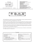
Unit
FRC-5 DTMF Paging
FTS-L7A CTCSS Tone Squelch
.
llv{IJ-z7 AsI Microphone
Unit
MH-26csyMicrophone .
Cut out the label at the right and place
it behind the clear plastic window in
the spine of the manual binder.
. . 4A-'t_
. . . .48-1. .4C
. . 4D-7
FT-2500M
Technical Supplement
V'
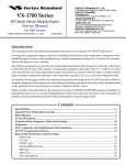
Introduction
The FT-2500M is Yaesu's new successor to the
famous FT-2400H, the industry's first amateur
transceiver designed to meet rugged U'S' military specifications for shock and vibration (MILSPEC 810-C). The FT-2500M is upgraded with a
new front panel and control knob layout, and
additional operator features.
Selectable power output of 5,25 or 50 watts
without the need of forced air cooling is possible
due to the large heatsink surface area of the compartmentalized one-piece diecast chassis. Backlighting for the large LCD (display) and knobs is
m-anually adjustable, or automatically controlled
by a photosensor, and the less-used buttons have
a flip-down protective cover. The thirty-one tunable memories can each be programmed with a
4-character channel name, which can thenbe displayed in place of frequency, as desired.
Each memory offers complete programmabil-
ity and scanning functions, such as independent
tx/ rx frequencies, independent repeater offset
and CTCSS tone, prografiunable scan limits, selectable scan resume modes and memorY skiP,
priority monitoring and a l-touch instant-recall
CALL channel. Channel steps are user-selectable
from 5 to 50 kHz, and Automatic Repeater Shift
can set standard repeater shifts when you tune to
a repeater subband. A1750-Hz tone generator is
included in European versions. A 39-tone Pro-
grammable CTCSS encoder is built in as standard, and the FTS-17ACTCSS unit canbe installed
to provide tone squelched private channels and a
CTCSS paging bell feature to sound a paging
alert tone when the tone squelch opens.
DTMF (Dual-Tone, Multi-Frequency) -based
selective calling and private paging capabilities
can be easily added with the optional FRC-6,
controlled entirely from the front panel. You can
select any of 999 3-digit ID codes for your transceiver, and then have your receiver stay quiet
until your code is received (frorn any standard
DTMF-equipped transceiver). When a call is received, the FT-2500M displays the caller's code,
and a pagingbeeper canbe set to sound and even
to respond to the call automatically. Seven DTMF
code memories store your ID plus those of six
other frequently-called stations or grouPs you
wish to monitor.
1-1
FT-2500M Technical Supplement
Specifications
General
Range:
Channel Steps:
Frequency Stability:
Mode of Emission:
Antenna Impedance:
Supply voltage:
Frequency
Current Consumption
(typical):
Range:
Case Size (WHD):
Weight:
Operating T"*p.
t44-146 or 148 MHz T>; or 144-146 MHz or 1.40-174MHz
5,10,L2.5,I5,20,25 &
< +10
ppm
50
Rx
kHz
(-20" to +60'C)
G3E (F3)
50 ohms, unbalanced
13.8
VDC
+10"/", negative ground
Rx: 600 mA, Tx
hr/mid/low:12/9/5A
-20o to +60" C
160 x 50 x 180
1.5
mm (w/o knobs)
kg (3.31b.)
\-/
Transmitter
OutputPower (high/mid
/\ow):
Type:
MaximumDeviation:
Spurious Radiation:
Microphone Impedance:
Modulation
,_____,
50/25/5W
Variable Reactance
t5 kHz
less than -60 dB
2kQ
\v
Receiver
Circuit
Type:
Double Conversion Superheterodyne
IFs:
21.4}l4'}lz & 455 kHz
Sensitivity (for 12dB SINAD): better than 0.2 pV
Selectivity (-6/-60
dB):
Rejection:
Image Rejection:
Maximum AF Output:
IF
12/30kHz
better than 70 dB
better than 70 dB
3.5
W into 4 ohms @10% THD
Specifications are subject to change without notice or obligation.
1-2
t-
FT-2500M Technical Supplement
r
p Component Information
The diagrams below indicate some of the
distinguishing features of common chip components.
Capacitors
(Unit I
>.1l\\
mm)
Type
L
w
T
3216
3.2
t.6
0.45-0.60
2125
2.0
1.25
0.35-0.50
608
t.6
0.8
0.65-0.95
r
Tantalum Capacitors
-@
Q
Type
RMC 1/10W 1/16W
Marking* I00,222,47 3""
Resistors
L
/t0
2.0
1.25
0
.45
0
0
r0"
/16
t.6
0.8
0.45
I
1
l0'
2
2
3
3
4
4
td
td
t0
5
5
10'
6
6
td
7
7
10'
B
B
tCI
1
INDICATED LETTERS
12 tl
t0
T
ll
Type
t
55
w
t--l
Ten unit
"
!a
TO
o
One
I
I
Examples
i
100
222
473
:
:
td
10O
2.2kO
:47kQ
1-3
FT-2500M Technical Supplement
\-------_
Chip Component Information
Replacing Chip Comp onents
Chip components are installed at the factory
by a series of robots. The first one places a spot
of adhesive resin at the location where each
part is to be installed, and later robots handle
and place parts using vacutun suction.
For single-sided boards, solder paste is applied and the board is then baked to harden the
resin and flow the solder. For double-sided
boards, no solder paste is applied, but the
board is baked (or exposed to ultra-violet light)
to cure the resin before dip soldering.
Precautions for Chip Replacement
X Do not disconnect a chip forcefully, or the
foil pattern may peel off the board.
X Never re-use a chip component. Dispose of
all removed chip components immediately
to avoid mixing with new parts.
X Limit soldering time to 3 seconds or less to
avoid damaging the component and board.
Remouing Chrp Comp onents
3
a time, using solder wick whetted with
non-acidic flux as shown below. Avoid applying pressure, and do not attempt to remove the tinning from the chip's electrode.
In our laboratories and service shops, small
quantities of chip components are mounted
manually by applying a spot of resin, placing
them with tweezers, and then soldering by
very small dual streams of hot air (without
physical contact during soldering). We remove
parts by first removing solder using a vacuurn
suction iron, which applies a light, steady vacuum at the iron tip, and then breaking the
adhesive with tweezers.
The special vacuum soldering/desoldering
equipment is recommended if you expect to do
a lot of chip replacements. Otherwise, it is
usually possible to remove and replace chip
components with only a tapered, temperaturecontrolled soldering iron, a set of tweezers and
Remove the solder at each joint, one joint at
tr
Grasp the chip on both sides with tweezers,
and gently twist the tweezers back and
forth (to break the adhesive bond) while
alternately heating each electrode. Be careful to avoid peeling the foil traces from the
board. Dispose of the chip when removed.
D
After removing the chip, use the copper
braid and soldering iron to which away any
excess solder and smooth the land for installation of the replacement part.
braided copper solder wick. Soldering iron
temperature should be less than 280'C (536
"F).
1-4
FT-2500M Technical Supplement
Chip Component Information
Install
\__
a Replacement Chip
As thevalue of some chip components is not
indicated on the body of the chip, be careful to
get the right part for replacement.
D Apply a small amount of solder to the land
on one side where the chip is to be installed.
Avoid too much solder, which may cause
bridging (shorting to other parts).
\=\
fl
Hold the chip with tweezers in the desired
position, and apply the soldering iron with
a motion line that indicated by the arrow in
the diagram below. Do not apply heat for
more than 3 seconds.
tl
Remove the tweezers and solder the electrode on the other side in the manner just
described.
1-5
FT-2500M Technical Supplement
Notes
1-6
FT-2500M Technical Supplement
Circuit Descripton
Receioe Signal Path
Incoming RF from the antenna jack is delivered to the Main Unit and passed through a low-
pass filter and a I/+-wave antenna switching
network consisting of coils L1003 & Ll-004, capacitors C1003 & C1004, and diodes D1001 &
D1025. Signals within the frequency range of the
transceiver are then passed through a varactortuned bandpass filter consisting of T1001/T1002
before RF amplification by Q1001 (3SK131). The
amplified RF is then bandpass filtered again by
varactor-tuned resonators T1,003/T1004, to en-
sure pure in-band input to 1st mixer
Q1002/Q1003 (2SK302GR x 2).
Buffered output from the VCO Unit is amplified by Q1005 (25C2759) and lowpass filtered by
LL009 and C1.042/C1043, to provide a pure 1st
local signal between LL8.6 and 152.6MH.2 to the
1st mixer. The 21.4-MHz 'l.st mixer product is
passed through dual monolithic crystal filter
XF1001 & XF1002 (t7.5 kHz BW) to strip away all
but the desired signal, which is then amplified by
Q1004 (25C2714Y).
The amplified 1st IF signal is applied to FM IF
subsystem IC Q1008 (MC3372ML), which contains the 2nd mixer, 2nd local oscillator, limiter
amplifier, noise amplifie1, S-meter amplifier and
squelch gates. A 2nd local signal is generated
from 21.855 MHz crystal XL001, which produces
the 455 kHz 2nd IF when mixed with the 1st IF
signal within Q1008. The 2nd IF is passed
through ceramic filter CF1001 to strip away unwanted mixer products, and then applied to the
limiter amp in Q1008, which removes amplitude
variations in the 455 kHz IF before detection of
the speechby ceramic discriminator CD1001.
Detected audio is delivered from Q1008 to the
CNTL Unit, where it passes through buffer amplifier Q2018 (2sc2712cR) and audio gateQ2002
(DTC114EK) before de-emphasis, and high-pass
filtering by Q2001-2 (NJM29O2Mj/4). Another
audio muting gate, Q2003 (DTC114EK), passes
the signal, which is then combined with beeper
audio originating from the microprocessor
through Beeper volume trimrner VR2001. The
level of the combined receiver and beeper audio
on the CNTL Unit is set by VOL potentiometer
VR3002 on the DISP Unit and is then retumed the
Main Unit for amplification by Q1023
(TDA2003H) up to 2 watts for the optional headphone jack or 8-ohm loudspeaker.
Squelch Control
The squelch circuit consists of noise amplifier
Q1007 (2S'C2712GR) and a highpass filter and
squelch trigger within Q1008 on the MAIN Unit,
and control circuitry within microprocessor
Q2006 (SC418082CFU) on the CNTL Unit.
When no carrier is received, noise at the output of the detector stage in Q1008 is amplifiedby
Q1007 and highpass filtered by the noise amp
section of Q1008, and then rectified by D1012 to
provide a DC control voltage for the squelch
switching section within Q1008. With no carrier,
pin 14 of Q1008 is high. This signal is inverted by
Q1006 (lMHs) and delivered to BUSY pin 15 of
main microprocessor Q2006 on the CNTLUnit as
the Scan Stop signal, which causes the BUSY indication on the display when the squelch is open.
This signal also causes the microprocessor to cut
receiver audio in two places on the CNTL Unit
mentioned already: opening audio mute gate
Q2002, and pulling the audio line to ground just
before the audio amplifier at Q2003, thus silencing the receiver while no signal is being received,
and during transmission.
When a carrier appears at the discriminator,
noise is removed from the output, causing pin 1,4
of Q1008 to go low. This signals the microprocessor to activate the BUSY indicator through LCD
driver Q3001 (LC7582E). The microprocessor
then checks for CTCSS tone detection from the
FTS-17A Tone Squelch Unit (if installed), and for
Digital Code Squelch information (if the FRC-6
Pager Unit is installed). If not transmitting and
tone squelch is not activated, or if the received
tone mitches that programmed, the microprocessor switches Q2002 and Q2003 to allow audio to
pass to the amplifier and loudspeaker.
Center-Stop Scanning
To ensure that scanning stops at the center of a
detected signal, discriminator output from pin 9
of Q1008 is also delivered to comparator circuit
Q2001 (NJM2902-3/+ & -a/+) on the CNTL Unit,
which compares the discrirninator output to a
preset DC level. The output of the comparator
connects to the Scan Stop line, preventing the
received signal from signalling the microprocessor to stop scanning until the signal has been
1-7
FT-2500M Technical Supplement
Circuit Description
tuned to its peak level, preset by Center-Stop
trimmer VR2007.
Transmit Signal Path
Speech input from the microphone is delivered via the Mic (]ack) Unit and DISPLAY Unit to
the CNTL Unit, where it passed through Mic
Mute switch D2003 (DAP202K) for amplification
and pre-emphasis by Q2007-1 (NJM2902M-1/4).
To prevent over-deviation, the audio is processed
by IDC (instantaneous deviation control) stage
Q2007-2/a, and then lowpass filtered by Q2007-3/t
&. -41+(N,naz9o2M) before delivery to the modulator on the VCO Unit.
If a CTCSS tone is enabled for transmission,
the subaudible tone from microprocessor Q2006
on the CNTL Unit is lowpass filtered by Q2001,-t
and mixed with the IDC-processed speech audio.
Also, DTMF tones generated by the FRC-6 option(if installed) or directly from the microprocessoq, are applied to the transmit audio chain at the
input of the IDC stage. The microprocessor also
disables microphone at Mic Mute switch D2003.
The modulating audio is delivered to diode
D305 (1SV214) on the VCO Unit, frequency
modulating the PLL carrier up to + 5 kHz from
the unmodulated carrier at the transmitting frequency. The modulated signal from transmitter
VCO Q303 (2SC3356) is buffered by Q305
(2SC2759) and delivered to the Main Unit for
amplification by Q1.01.2 (2SC2759), Q1011
(MMBR951L) and Q1010 (2SC20s3). The low
level transmit signal is then finally amplified by
PA module Q1009 (M67781L) up to 50 watts.
Harmonic spurious radiation in the final output
is suppressed by a 3-pole lowpass filter on the
Main Unit, and the transmit signal then passes
through 1/+-w av e antenna switch D1 0 1 6 ( U M 94 1 5)
before delivery to the antenna.
Spurious Suppression
Generation of spurious products by the transmitter is minimized by the fundamental carrier
frequency being equal to the final transmitting
frequency, modulated directly in the transmit
VCO. Additional harmonic suppression is provided by a 3-pole lowpass filter consisting of
LL002, LL013, LL01,4 and C1002, CL061, C1.063,
C1065-C1067, and C1I64, resulting in more than
50 dB harmonic suppression (for transmitting
frequencies in the amateur band) prior to delivery to the antenna.
PLL Erequency Synthesizer
PLL circuitry on the Main Unit consists of
prescaler Q1025 (MC12O22SLAD) and PLL subsystem IC Q1024 (MC1451 s9F2),which contains
a reference oscillator / divider, serial-to-parallel
data latch, programmable divider and a phase
comparator. Stability is obtained by a regulated
5-V supply to Q1024 and temperature compensating capacitors associated with L2.8-MHz frequency reference crystal X1002.
Receiver VCO Q301 (2SC3356) on the VCO
Unit oscillates between 118.6 and 152.6 according
to the programmed receiving frequency. The
VCO ouput is buffered by Q305 (2SC2759) on
the VCO Unit, and then retumed to the MAIN
Unit where a sample of the output is buffered by
Q1028 (2S,C2714Y) for application to prescaler/swallow counter Q1025. There the VCO signal is
divided by 64 or 65, according to a control signal
from the data latch section of Q1024,before being
applied to the programmable divider section of
the PLL chip.
Power Controller Q1019 (2581143S) which
The data latch section of Q1024 also receives
serial dividing data from microprocessor Q2006
on the CNTL Unit, which causes the predivided
VCO signal to be further divided by 23,720
30,520 in the programmable divider section, depending upon the desired receive frequency, so
as to produce a S-kHz or 6.25-kHz derivative of
the current VCO frequency. Meanwhile, the reference divider section of Q1024 divides the 12.8MHz crystal reference by 2560 (or 2048) to
produce the S-kHz (or 6.25-kHz) loop reference
(respectively).
high, medium or.low output power under varying antenna loading conditions.
The 5-kHz (or 6.25-kHz) signal from the programmable divider (derived from the VCO) and
that derived from the crystal are applied to the
Automatic Tiansmit Power Control
RF power output from the final amplifier is
by CL064 and rectified by DL01.7
(1SS97). The resulting DC is passedbyhigh/medium/low power controller Q1017 (FMS1) and
transmit inhibit gate Q1018 (lMX1) to Automatic
sampled
regulates supply voltage to transmitter RF amplifiers Q1009 and Q1010, so as to maintain stable
1-8
FT-2500M Technical Supplement
t Description
phase detector section of Q1.024, which produces
a dual 5-V pulsed output with pulse duration
depending on the phase difference between the
input signals. This pulse train is converted to DC
by charge pump Q1026/QI027 (lMXs /lMZ2),
lowpass filtered, and then fed back to varactors
D301 and D302 (1T363 x 2) on the VCO Unit.
Changes in the level of the DC voltage applied
to D30L/D302 affect the reactance in the tank
circuit of VCO Q301, changing the oscillating frequency according to the phase difference between the signals derived from the VCO and the
crystal reference oscillator. The VCO is thus
phase-locked to the crystal reference oscillator.
The output of receiver VCO Q301, after buffer-
irg by Q305, is delivered to the Main Unit for
amplification by Q1005 before application to the
1st mixer, as described previously.
Transmitter VCO Q303 (2SC3356) oscillates
between 140 and 174MHz according to the programmed transmit frequency. The remainder of
the PLL circuitry is shared with the receiver.
However, the dividing data from the microprocessor is such that the VCO frequency is at the
actual transmit frequency (rather than offset for
IFs, as in the receiving case). Also, the transmitter
VCO is modulated by the filtered speech audio
applied to modulating varactor D305, as described previously.
Transmit Inhibit
When the transmit PLL is unlocked pin 7 of
PLL chip Q1024 goes to a logic low, tuming on
Q1020 (DTA143EK) and tuming off half of Q1018.
This unlock signal produces a low impedance at
the base of the other half of Q1018, which then
turns off Automatic Power Controller Q1019 to
disable the supply voltage to transmitter RF am-
plifiers Q1009 and Q1010, disabling the transmitter.
Mis cell ane ous Cir cuits
Power-On Sequencing
I
Panel Lamps
Pressing the POWER switch on the DISP Unit
turns onQ2017 (DTC114EK) on the CNTL Unit,
applying 5 volts from regulator Q2012 (L7805)
via 9-volt regulator Q1013 (AN6541 ) and the 13.8V supply line to the base of Q2016 (2581140S).
This pulls RESET pn75 of microprocessor Q2006
low, causing PO pin 66 to go high. The PO line
then pulls the base of Q2017 (DTC114EK) low,
lighting the pilot lamps via Q2005 (25C2712GR)
and Q2004 (2SB1143S). Lamp brightness is controlled by CdS photosensor CS3001, which provides an input to microprocessor Q2006, pn 49.
An pulsed DC ouput is then applied to the integrator circuit formedby C2015 and M021, which
produces a DC bias proportional to the pulse
train input, which is then applied to the base of
Q200s (2S,C2712GR), and Q2004 (2SB1143S),
controlling voltage to the panel and display
lamps.
P u sh-Tb
-Talk Tr an s mit Ac t ia at i o n
The PTT switch on the microphone is connecpn 44 of microprocessor Q2006, so that
when the switch is closed pn69 (tx/rx) goes low.
This signal is delivered to power bus controller
Q1021 (lMHs) on the MAIN Unit, which then
disables the receiver by disabling the 9-V supply
bus at QI022 (DTA143EK) to the front end, IF,
discriminator and receiver VCO circuitry. At the
same time, Q1015 (2581143S) activates the
transmit 9-V supply line to enable the transmit-
ted to
ter.
1-9
FT-2500M Technical Supplement
Notes
1-10
FT-2500M Technical Supplement
tI
uM94
1
5
T/R ANT
SW
Qro05
2SC2759
BUFF
01 028
cFt001
25C27 1 LY
cF\v455E
455KHz
BUFF
01025
MC
1
2022SLAD
PRE SCALER IC
VCO_UN I T
[_
F3152101A
MArN-UNtT 73427000
+--!----------
TX
RX
COMMON
FT-2500M Technical Supplement
8201
1
I MH5
PO ADJ
--1
l;;l
2SC3356
I
RFpRrvE
F---1
I
l.*"1 l;;l
MMBRgsit
I
RFAMP
t ---{
I
BUFF rI
RX
I
22.6-
TY
I
44.0*i
1
26
j
41004
zsc27 i /*\
2sc27se
I
IF
SW
ttt"tttt'"-tl i'
Ljf'
AMP
- - - Jg[E-
I
.6ltqz
48.OMHz
01008
IF IC
i
I
MC3372M
OSC, FM MOD)
END MIX,
I
01028
RESET
cF1001
cFw4s5E
25C27 1 1Y
BUFF
45sKHz
l-.r*t-
4302
07c1zLEk
T,/R SW
|
1-'t'#5
01021
I
MH5
T,/R
I
il--
VCO_UN
IT
F3152101A
SW
il
I
l
2SC
Q2oo6, 9, 1 0.
1
623-L5, RHSVA4sAA,
CNTL.UN
I
T
s.
D200
'34261C1
0S300
TX
I
DTC I 1 4Et
RESET CIRCUI
1
FT0-1 0262A8 (gP-28)
LCD
RX
D
COMMON
IAL
j j orrr- rueur
trl+
---1:---] '
l*,
l-
Block Diagram
2
21M1sBU
I . I'MHz
CLON E
I
02001
DATA
MCF
-3. -4
NJM2902Mx 2
CTR STOP
1r004
F
AMP
01008
C
PAGER_UN I T
MC3372M
OND MIX, OSC. FM
FRC-6
(oPT
MOD)
r
0N)
01007
FIL
Ii
AMP
i_i
I I
-i-J
ll
It-Jl
ntooT-L
rruzgozv
I
ru*'*t
surr
I
lr-i -.t
LPF li
I
il
lL
NJM2302M
I
r,lrc uure
i
F-r-
I
0r021
02003
MH5
T,/R
I
DTC
AF
SW
02006, 9, 1 0,
1
I
s,
02004, 5, 8,
I
623-L5, RHsVA4sAA, OTCl 14EK, FMAl,
RESET CIRCUIT
cNTL-UN
I
T
1 1
4EK
MUTE
DAP2O2KX4
a34261C1
rD
IAL
DATA
I
ttti
I nrAr
t\
IV
l___i
rNPlir
)
l-"
KEY
rl/1
I NPUT
1+
MIC
'----l---\_l
DISP_UNIT
'34261
g'J
1-11
l--;^-*;-;;;il--l
ffi+
J1003
S-IlETER
P0003
:
I
I
F--"1
LlH
IIOISE
t3.8V
GND
SOL
VR
DISC
OUT
oUT
NOISE
wtl/L
H,/v/L
gWED
13.8V
INPUT
SWED
t-
l------'
ii PAGER-U|
(OPT 0r
I
VCO-UN I T
F3152101A
lD-tS:€vl
F
SCAN STOP
VR
INPUT
13.8V
T
S-METER
SCAN STOP
DISC
I
J2007 Pl090838
POO90833
SOL
T9zo6o87
wtRE assY
CNTL-UN
r
I
r__________i
t_______
t*-----'
I
I
GND
T0NE SaL(0PT t0t
GND
9V
9V
AF
AF
T/R
T/R
Nq
NC
6ND
GND
PSTB
PSTB
DATA
DATA
CLOCK
CLOCK
GND
GND
MOD
MOO
5v
SP
AF
GND
r3.8V
J1 004
AF
SP
J1002 P0090787
J2008
I
I
I
t-----
FT-2500M Technical Supplement
SP
13.8V
I
J
I
I
t-----
P10SO83S
l--;;*;;-;;;;;--l
MAIN_UNIT F3427OOO
J200s
GND
JI003
P0090833
S-METER
$CAN STOP
SOL
DISC
t{O
ISE
VR
OUT
J2007 Pt090838
S-METER
SCAN STT]P
0t8c
INPUT
NOISE
vl/L
H/M./L
r3.8V
SVED
13.8V
r---------l
! t.ls2r01A
vco-ururr
ir-_________i
DATA
DAiF'
l---------l
I
!rl
I
I
I
i
pnorn-uNrr
topr
rou
I
I
ISP-UN
CE
INH
CLOCK
DATA
POTVER
o/vR
F/il
F/\t
REV
REV
MHz
MHz
,l
LO}Y
L0v'
I
RPT
RPT
{
r__________i
TgNE
PAOE
PAGE
r---------l
r T0NE
T
torr
rou
ir__________i
CALL
CALL
D(
OIMC
DIMC
JP3O
SQL-UN
I
!
i
UP
DOWN
GND
UP
DOIYN
GND
PTT
PTT
SV
SV
ACC
ACC
AF
AF
DIM
DIM
T/R
GND
GNO
T/R
NC
SF
EP
GND
5V
5V
PSTB
PSTB
5V
DATA
DATA
GND
NC
GND
5V
GI{D
CLOCK
soL
I
SqL I
GND
GND
s0L2
s0L2
MOD
MOD
CND
CLOCK
AF
5v
5V
SP
AF
r3.8V
J1002 P0090787
AF
GND
AF
SP
utc
13.8V
AF2
AF2
GND
GND
\,2008
F3/*2610
TONE
I
IP
IT
GND
OIALl
POWER
SWEo
D
\,3001
DIALl
CLOCK
INPUT
I
DIAL2
INH
ouT
A0651
r
DIAL2
CE
SOL VR
T9206352A
WIRE ASSY
P1
090839
D IMC
J2006
Mrc
D IMC
J3002
Interconnection Diagram
NtT F3425101
I
J2005
\,300.|
GND
DIAL2
DIALI
DIALI
INH
CLOCK
OATA
PgWER
D/MR
\GER_UN
I
T
oN)
____-__t
(oPT
r
|
I
CE
INH
CLOCK
FOWER
D/IIR
F/\t
ACC
REV
REV
SP
MHz
MHz
PTT
PTT
Lolv
L0w
Mtc
Mrc
RPT
RPT
GND
TONE
PAGE
PAGE
UP
CALL
CALL
DOWN
D IMC
DIMC
SQL-UN I T
(0PT t0N)
UP
DOWN
UP
DOWN
PTT
PTT
ACC
ACC
DIM
DIM
GND
GND
SF
8P
5V
5V
sv
5V
GND
SQL
1
saL2
GND
AF
Mtc
I
5V
TONE
E
I
MIC_UNIT
F3426 1 03
DATA
/'ll
F
I
GNB
DIAL2
CE
'------t
t--;;;;-,;;;;l
GND
SOL
GND
AF
Mtc
AF2
AF2
GND
GND
D IMC
J2006
1
saL2
D IMC
J3002
JP3001
ACC
SP
GND
5V
UP
DOWN
JPl 501
@)(
Screw List
RE
F.
YAESU P,/N
otv.
Descr i otion
O
u00306001
PAN HEAD SCREW M3X6
i
@
u06408007
SCREW OM4 X BB
2
@
u20206001
BIND]NG HEAD SCREW M2.6
@
u20306001
BINDiNG HEAD SCREW M3
X6
o
u20306002
BINDING HEAD SCREW M3
X
6Ni
2
@
u20306007
X
68
8
o
u20308001
BINDING HEAD SCBEW M3
BINDING HEAD SCREW M3
@
u20308002
BINDING HEAD SCREW M3
X
o
u30206001
FLAT HEAD SCREW M2.6 X 6
o
@
u30306007
FLATHEAD SCREW M3X68
1
o
u43206001
CA
u43306001
TAPTITE SCREW M2.6 X 6
TAPTITE SCREW M3X6
4
@
u51425007
HEX SOCKET HEAD BOLT I,t4 X 25B
2
X6
2
1
X8
CNTL Unit
2
I
8Ni
1
TS206352A
WIRE ASS'Y (2Pcs)
Basic Accessories
YAESU P,/N
Descr i ption
Otv.
Q0000008
FUSE 15A
2
r9018615A
DC CABLE
I
806517500
OPERATING MANUAL
1
DISPLAY Unit
P1
090677
R3520140
RU BBER
R35201 808
RUBBER KNOB
R35201 708
RUBBER KNOB
R3520200A
PANEL
WINDOW
R3520
1
R3520
20
SPEAKER
RUBBER KNOB
RUBBER KNOB ASS'Y
R3520
1
RUBBER KNOB
RUBBER KNOB ASS'Y
€)@\
6\
FT-2500M Technical Supplement
Exploded
\
R3806750
CASE TO;
CNTL Uni
T9206352A
WIRE ASS'Y (2pcs)
DISPLAY Unit
R3520140
RU BBER
R35201 808
RUBBER KNOB
rti
r9206000c
R3520
RUBBER KNOB
T9206082
WIRE ASS'Y
R3520
ASS'Y (2pcs)
M
1
R3520
1
RUBBER KNOB
R3520100
RUBBER KNOB ASS'Y
4090067
SPEAKER
RUBBER KNOB
WIRE ASS'Y
Exploded View & Miscellaneous Parts
P
1
090352
CONNECTOR
R490081 1
CHASSI S
P
1
090654
CONNECTOR
Jvatt'r unir
IVCO Unit
T
WIRE ASS'Y
R3806730
,CASE
BOTTOM
Non-designated parts are available
only as part of a designated assembly.
Case Disassembly and PCB Access
LCD
3
€s
Control Unit Access
To access the Control Unit and Display Unit
first remove the VOL, SQL and dial knobs by
gently pulling them outward.
Lithium Backup Battery Replacement
The lithiumbackup battery should not require
servicing for a period of several years, howeveq,
to replace the cell, order Yaesu P/N Q9000552.
O First note the location and tab polarity of
8T2001, mounted over the CNTL Unit microprocessor. To remove the old cell, carefully
unsolder each terminal from the CNTL Unit
PCB and lift it free.
a
Next remove two screws from each side of the
top cover and one from the rear. Tilt the rear of
the cover upward, then slide it out from the
chassis. Note that the single rear screw is different from the other four, be sure to reinstall it
in the correct location. Be careful not to lose the
plastic plug covering the cable entrance cutout
in the chassis.
lithium batteries according to regulations in your area, and ensure small children cannot play with or accidentally ingest thebattery.
Dispose of
O Mount the replacement cell similarly, observing proper polarity when installing it. Next,
place the plastic insulating seal (P/N
cellbypeelingbackthe
cover to expose the adhesive backing, then
pressing it in place.
R8118690) on top of the
o
Remove the two hex bolts from the front panel
using a 3.5 mm hexagonal driver, then gently
loosen the front panel.
tr
Remove the two flat ribbon cables by using a
small screwdriver or fingemail to slide the
release clamps forward on both sides of the
cable connector. After releasing both cables,
gently separate the front panel from the main
chassis and place it on a soft surface to prevent
the clear display from marring.
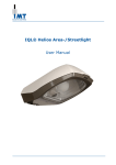
Panel Lamp Replacement
The LCD and controls are illuminatedby four
10-V incandescent miniature lamps. If these require replacement, they canbe ordered fromyour
Yaesu dealer (P/N Q1000083).
fl
First remove the front panel as previously described. Note the location of the four lamps, as
indicated below.
f:
i:
fl
W/Spacer
W/O
Spacer
To remove a failed lamp, use a low wattage
soldering iron and forceps to unsolder and
free each lead, then gently lift the bulb out of
the hole.
2-1
FT-2500M Technical Supplement
Modification for 9600-Baud Packet
No/e: The two lamps on either side of the LCD
use plastic spacers, be careful not to lose these
when removing the bulb, and insert them again
when instailing a new bulb.
fl
Install replacement bulbs in the reverse manthen reassemble the transceiver case.
ne4,
Modification for 9600-Baud Packet
Operation at high data rates requires special
interfacing since the FT-2500M bandwidth and
pre- and de-emphasis circuitry are not optimized
for this mode of operation.
If you want to use your FT-2500M with a9600baud Packet TNC, the following modification
should enable better performance at this higher
data rate. Howeveq, throughput performance at
9600 baud is not guaranteed.
Part
QTY.
2 pc. 0-O chip resistor
1
pc.
2
pc.
2
pc.
1O-kA chip
resistor
lengths of
wire
1-pF tantalum
chip capacitor
Fig.
2
RX Audio Component Location
If you arenot confident at surfacemount soldering,
do not attempt the modification, and contact your
for assistance.
Remove the top cover as described on the previous page to expose the CNTL Unit. Refer to
Fig. 1 to familiarize yourself with the part locations.
Yaesu dealer
fl
Comments
*Read notice at below right.
You may have to experiment
with this value for optimum
audio input level.
Use stranded #22 AWG,
approx. 5 cm in length.
lf your TNC model does not
have a capacitive-coupled audio
inpuVoutput, see the notice be-
low
Fig.
If you choose to perform this modification,
you will need a low-wattage soldering iron,
tweezers and the following components:
J
3
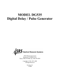
TX Audio Component Location
Locate the unused pad beneath connector
J2004, labeled C (Fig. 2). Install a 0-O chip
resistor* across at this location, and a wire to
the pad just to the left labeled DISC. This
makes the connection for de-emphasized discriminator audio output for decoding.
N'6iiCeL.
Fig.
1 Modification Component Location
2-2
FT-2500M Technical Supplement
Modification for 9600-Baud Packet
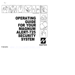
D Next locate the set of pads labeled MOD (c &
D
R), above connector J2008 (fig. 3). Solder a
10-kO chip resistor across pad R, and a 0-Q
chip resistor* across pad C, and a wire lead to
the adjacent pad. Pre-emphasized audio is fed
to the transmitter here.
Note the small plastic plug in the chassis cutout at the rear left corner of the CNTL Unit
compartment. Remove this plug, then run the
leads from your TNC through this cut-out and
solder them to the appropriate leads on the
CNTL Unit. Be sure to insulate any spliced
leads with heat-shrink tubing or electrical
tape.
0 After checking all connections for integrity,
replace the top cover and tighten all screws.
This completes the modification.
While this modification should work with most
units, experimentation with audio input and output leoel may be necessary before optimum performance is obtained.
03022
Fig.
4 TNC DATA IN/OUT
Lead Connections
2-3
Ff-2500M Technical Supplement
Channel Display-Only Mode
Channel Display-Only Mode
You can use this feature when you need very simple operation: only stored memories can be
selected, and are displayed as "!1.!-1. l, .-t,..." instead of the channel frequency or alphanumeric
name display. L:rdicators for preoiously stored settings such as repeater shift and tone squelch are
still displayed, although they cannot be changed. Only the settings listed below can be changed
as described
X High/Mi d./Low TX power and locking function: ,tt" ffil t@=@l to toggle
X Volume & Squelch: same as before
X Channel Selection: DIAL knob or microphone UP/DWN keys
X Paging function selection: toggle @ ,o select paging mode
X Paging code memory selection: press @= @ and rotate DIAL knob to select
X CALL channel instant recall: pt"tt 6tlD to toggle
X Priority channel recall:press (EHfl to toggle
After programming memories, you can activate Channel Display-Only operation by turning
the trans'ceirier off, thin pressing ind holding th" @ & gg, keys together-while powering on
again. Repeat this step to return the transceiver to normal.
2-4
FT-2500M Technical Supplement
Alignment
The FT-2500M has been carefully aligned at
the factory for the specified performance across
the amateur band. Realignment should therefore
not be necessary except in the event of a component failure. A11 component replacement and
service should be performed only by an authoized Yaesu representative, or the warranty policy maybe voided.
equipped for repair and alignment. Therefore, if
a fault is suspected, contact the dealer from
whom the transceiver was purchased for instructions regarding repair. Authorized Yaesu service
technicians realign all circuits and make complete performance checks to ensure compliance
with factory specifications after replacing any
faulty components.
The following procedures cover the sometimes critical and tedious adjustments that are
not normally required once the transceiver has
left the factory. However, if damage occurs and
Those who do undertake any of the following
alignments are cautioned to proceed at their own
risk. Problems caused by unauthorized attempts
at realignment are not covered by the warranty
policy. Also, Yaesu must reserve the right to
change circuits and alignment procedures in the
interest of improved performance, without notifyit g owners.
some parts are replaced, realignment may be required. If a sudden problem occurs during nor-
it is likely
due to component
failure; realignment should not be done until after the faulty component has been replaced.
mal operation,
We recommend that servicing be performed
only by authorized Yaesu service technicians
who are experienced with the circuitry and fully
Under no circumstances should any alignment be attempted unless the normal function
and operation of the transceiver are clearly understood, the cause of the malfunction has been
Case Disassembly
n
Make sure the transceiver is off. Remove the
two screws from each side of the top and bottom covers, then loosen the two rear screws.
Next remove the top and bottom covers, the
CNTL Unit is now accessible from the top of
the chassis.
D To expose the Main Unit PCB on the bottom of
the transceiver chassis, remove the 5 screws
affixing the shield cover plate, and remove the
cover.
MAIN Unit
VCO Unit
CNTL
Unit_
DISPLAY Unit
MIC Unit
2-5
FT-2500M Technical Supplement
clearly pinpointed and any faulty components
replaced, and the need for realignment determined to be absolutely necessary.
Correct alignment requires that the ambient
temperaturebe the same as that of the transceiver
and test equipment, and that this temperature be
held constant between 20o and 30' C (68' - 86 'F).
When the transceiver is brought into the shop
from hot or cold air it should be allowed some
time for thermal equalization with the environment before alignment.
The following test equipment (and thorough
familiarity with its correct use) is necessary for
complete realignment. Correction of problems
caused by misalignment resulting from use of
improper test equipment is not covered under
the warranty policy. While most steps do not
require all of the equipment listed, the interac-
If possible, alignments should be made with
oscillator shields and circuit boards firmly affixed in place. Also, the test equipment must be
thoroughly warmed up before beginning.
Note: Signal levels in dB referred to in this proce-
tions of some adjustments may require that more
complex adjustments be performed afterwards.
Do not attempt to perform only a single step
unless it is clearly isolated electrically from all
other steps. Have all test equipment ready before
beginning, and follow all of the steps in a section
in the order presented.
Re
tr
D
D
D
D
D
n
D
quir e d T e st E quipment
RF Signal Generator with calibrated output
level at 200MHz
Deviation Meter (linear detector)
AF Millivoltmeter
SINAD Meter
Inline Wattmeter with 5% accuracy at 200
MHz
Regulated DC Power Supply: adjustable from
10 to 17 VDC, 15A
50-C) RF Dummy Load: 100W at 200 MHz
Frequency Counter: + 0.1ppm accuracy at 200
MHz
O AF Signal Generator
tr DC Voltmeter: high impedance
D VHF Sampling Coupler
D AF Dummy Load: 8 Q,5W
dure are based on 0 dBp = 0.5 pV(closed circuit).
PLL E Transmitter
Set up the test equipment as shown for transmitter alignment. Maintain the supply voltage at
13.8V DC for allsteps.
PLL & Tlansmitter Alignment Setup
Sampl ing
Coupler
,
PLL VCV (Varactor Control Voltage)
D Connect the positive lead of the DC voltmeter
to the test point VCV on the Main Unit, as
indicated in the figure, and the negative lead
to chassis ground.
Alignment Prep ar ation €s Pre c autions
A 50-O dummy load and inline wattmeter
must be connected to the main antenna jack in all
procedures that call for transmission, except
where specified otherwise. Correct alignment is
not possible with an antenna.
VCV Test Point
After completing one step, read the following
step to determine whether the same test equipment will be required. If not, remove the test
equipment (except dummy load and wattmete{,
if connected) before proceeding.
2-6
FT-2500M Technical Supplement
v
Alignment
PLL & tansmitter Alignment Points
D
Set the transceiver to the 174.000 MHz*, and
adjust coilL303 on the VCO Unit for 7.5 V on
the voltmeter.
*For transceiaer aersions without extended receiae
capability, tune to 146.000 MHz and adjust L303
for 1.8 V on the aoltmeter.
D
Panel Power
Selection
Adjustment
Power Output
High
vR2005
50+5W
Mid
vR2003
25+1W
Low
vR2004
5+1W
Next tune to 146.000 M}{4key the transmittet
and adjust L304 for 1.8 V on the voltmeter.
Transmitter Deaiation
PLL Reference
F re
quency
D With the wattmeter, dummy load and frequency counter connected to the antenna jack,
and while tuned to 146.000 MH4 key the
transmitter and adjust TC1001 on the Main
Unit, if necessary, so the counter frequency is
within 100 Hz of 146.000 MHz.
D \tVhile tuned to
146.000 MHz, adjust the AF
generator level for 50 mV output @ l kHz to
the MtC jack.
O Key the transmitter and adjust VR2002 on the
CNTL Unit for + 4.5kHz deviation on the deviation meter (within 100 Hz),
Tiansmitter Output
D Preset trimmer potentiometers VR2003,
VR2004 and VR2005 fully clockwise.
O Vfhile tuned to 146.000 MHz, press the LoW
button on the panel to select high, mid- and
then low power while adjusting the corresponding trimpot for the transmitter Power
output levels listed in the table:
2-7
FT-2500M Technical Supplement
r
Receiaer
S-Meter Calibration
up the test equipment as shown below for
receiver alignment.
D \tVhile tuned to 146.000 MHz,inject a +25 dBp
RF signal modulated with 13.5 kHz deviation
of a L-kHz tone, and adjust VR2006 on the
CNTL Unit so that all S-meter segments are
Set
Receiver Alignment Setup
just on.
Scanner Center Stop
I
tr
Connect the DC voltmeter (3-V range) between TP2002 (+) and TP2001(-) on the CNTL
Unit.
Withboth the transceiver and signal generator
tune to 146.000 MH4 set the SQL control fully
counter-clockwise (the "ausy" indicator
should be on). Lrject 20 dBp RF modulated
with t3.5 kHz deviation of al-kHz tone, and
adjust VM007 on the CNTL Unit for 0 V on the
voltmeter.
Squelch
D
Int er st ag e Tr ansfo r mer s
D Connect the DC voltmeter between
7 and chassis ground.
J1003
pin
O Modulate the RF signal generator with t3.5
kHz deviation of a 1-kHz tone.
tr
Adjust T1001 - TL004, & T1006 on the Main
Unit for maximum voltage on the meter, then
once again for optimum SINAD (at least -7
dBp for 12 dB SINAD).
Preset the SQL control to the L0 o'clock position. At the center of the band, tune the RF
signal generator to the same frequency, and set
the generator level to -L2 dBp.
fl
Tum VR1001 clockwise until the squelch just
closes, and then counter-clockwise very
slightly so that it just opens.
Receiver Alignment Points
T1001
T1002
T1003
r1004
r1 006
J1003 PinT
vR 1001
vR2007
-
)
rP2002 ( +
)
rP2001
(
vR2006
2-8
FT-2500M Technical Supplement
VCO Unit
chiponly side
component side
Emitter
Basel I
1
'"fr'"'
eritt"r2
lrfi.-l
1"'.*
,
L*--J
I-il----ilI zzk I
Collstorl I
I
I
tlt
tr-{
t-t
llll
L']t.]
I
Collector2
Base 2
rvus
(Hs)
(os04)
DTCI24EK (25)
(0302)
2sc2759 (u22)
(0305)
2sc3356 (R24)
(o301.303)
NOTE:
VCO_UNIT F3152101A
BESISTOR VALUES AFE !N
CAPACIToF VALUES AFE lN
O.
INDUCIOR VALUES A8E ]N
H
!/IOW
rF. sov
;
:
O CAPACITOR VALUES ARE TANTALUU
UNLESS OTHEFVISE
To MAIN Unit
(Ss
Prg6
N''ED.
;
3&1)
3A-1
FT-2500M Technical Supplement
VCO lJnit
REF.
VALUE
DESCRI PT I ON
***
PCB
t.Iith
I'lV
VCO UNIT
TOL.
l'lF'GR'S DESIG
F3152101A
SpF 50V
10pF 50V
18pF 50V
15pF 50V
50V
lpF
47uF 16V
0.001uF 50V
50V
lpF
6pF 50V
15pF 50V
18pF 50V
22pF 50V
0.001uF
0.001uF
50V
50V
50V
2pF
0.001uF 50V
10pF 50V
0.001uF 50V
4pF 50V
0.001uF
0.001uF
0.001uF
50V
50V
50V
K22170206
CH
GRI'{4OCHO5OC5OPT
CH
GRll4OCHlOODSOPT
K22I7OZII
CH
GRl'{4OCHlBOJsOPT
K22170217
CH
GRl.,l4OCHl5OJ5OPT
CK
GRl'{4OCKOlOCSOPT
KZ2I70215
KZZ|T0202
B
GRM4OBlO2l'lSOPT
CK
GBl'l4OCKOlOCSOPT
CH
GRM4OCHO6ODsOPT
CH
GRl'{4OCHl5OJ5OPT
CH
GRl'l4OCHlSOJ5OPT
K22t70Zt5
KZ2t10Zt7
CH
GRM4OCH2ZOJSOPT
K22t702ts
B
GRM4OBlO2l'lSOPT
B
GAl'{4OBlO2l'lSOPT
K22170805
K22170805
CK
GRl',l4OCKO2OC5OPT
B
GRI'14OBlOzMSOPT
K22170243
K22i70805
CH
GRM4OCHlOODsOPT
KZ2r702tl
B
GRM4OBlOzMSOPT
K22170805
CH
GRl'{4OCHO4OCSOPT
B
GRM4OBlO2llSOPT
K22r70205
K22r70805
B
GRI.{4OBlO2l'{5OPT
B
GRI.14OBlO2l.l5OPT
16V470l',16X7TR2
K46120006
K22170805
K22170202
K22t70207
K22170805
K22170805
G2070rr4
DIODE
1T363-01-T084
1T363-01-T084
1T363-01-T084
1T363-01-T084
DIODE
1SVZ14 TPH
G2070356
LALO3NA4RTK
L1
LALO3NA4RTK
L1
s7-T2 R12-K868C
s?-T2 812-K8688
10190 168
FLC3ZT-2R2K
FLC3?T-2ft2K
11690207
11690207
TRANSISTOR
2SC3356-T2B H24
G3333567D
TRANSISTOR
DTC124EK T97
G3070034
TRANSISTOE
2SC3356-T2B R24
Il'{H5 T1O8
25C2759-T2B U22
G3333567D
5%
RMC1/1OT 273J
5%
5%
RMCl/1OT 273J
HMCI/TOT 222J
Rl{Cl/1OT 1OlJ
RMC1/1OT 273J
RI'{C1/lOT 273J
J24205273
J24205273
J24205222
J24205101
J24205273
J24205273
5%
RMC1/1OT 1O2J
J24205t02
D O3O1
D O3OZ
D O3O3
D O3O4
D O3O5
DIODE
L
L
L
L
L
L
O3O1
O3O2
M. RFC
0303
C0rL
0305
0306
M. R['C
Q
Q
Q
Q
Q
O3O1
O3O2
O3O3
O3O4
O3O5
R
R
R
R
R
R
R
O3O1
O3O2
O3O3
O3O4
O3O5
CHIP
RES.
CHIP
RES.
27K
27K
unl,/
t/r}w
CHIP
CHIP
CHIP
BES.
2.2K
1/10W
5%
BES.
100
r/llvt
5%
RES.
1/10W
5%
0306
CHIP
RES.
27K
27K
O3O7 CHIP
RES.
1K
DIODE
DIODE
4.?uH
4.?uH
M. RFC
O3O4 COIL
2.ZuH
2.ZuH
l'l. RFC
VERS.
c41305001
Board
CAP.
CAP.
CAP.
CAP.
CAP.
CAP.
CAP.
CAP.
CAP.
CAP.
0AP.
CAP.
CAP.
CAP.
CAP.
CAP.
CAP.
CAP.
CAP.
CAP.
CAP.
CAP.
C 0301 CHIP
C 0302 CHIP
C 0303 CHIP
C 0304 CHIP
C 0305 CHIP
C 0306 AL. ELECTR0.
C 0307 CHIP
C 0308 CHIP
C 0309 CHIP
C 0310 CHIP
C 0311 CHIP
C 0312 CHIP
C 0313 CHIP
C 0314 CHIP
C 0315 CHIP
C 0316 CHIP
C 0317 CHIP
C 0318 CHIP
C 0319 CHIP
C 0320 CHIP
C 0321 CHIP
C 0322 CHIP
P/N
*xx
Components
Printed Circuit
YAESU
TRANSISTOR
TRANSISTOR
r/tlw
ur}lil
G2070n4
G2070fi4
G2070n4
L0
190203
190203
1
90 169
G3070027
G332?597B
3A-3
FT-2500M Technical Supplement
VCO Unit
RBF.
R
R
R
R
R
DESCRIPTION
O3O8 CHIP RES.
O3O9,CHIP
CHIP RES.
O31O
0311
0312
TOL.
r/nw 5%
10K
L/t}lw
RES.
RES.
zZK
5%
r/nw 5%
vnl!/-
r/nw
5%
5%
I'IFGR'S DESIG
Rl'{Cl/1OT 332J
RMCl/1OT 1O3J
HMCT/IOT 22IJ
RMC1/1OT 152J
RMC1/1OT Z23J
l',lK-i0160
TPO301 TP-H
TPO3O2 TP-H
TPO3O3 TP_H
TPO3O4 TP_H
TPO305 TP-H
SHIELD
lllv
3.3K
220
1.5K
RES.
CHIP
CHIP
VALUE
l'{K-10160
MK-10160
},tK-10160
l'{K-10160
CASE
YAESU
P/N
VERS.
J24205332
J24245r03
J2420522t
J24205t52
JZ4Z05ZZ3
Q5000037
Q5000037
85000037
Q5000037
Q5000037
R01362408
3A-4
FT-2500M Technical Supplement
\/V-,:
O1008 Pin
Rl\::;
O1008 Pin
7
455kHz
MAIN-UNIT
2
01008 Pin 8 455kHz
01024 Pin
-0v
1
v
\r_
2.gv
\/V::
O1024 Pin
,9.0V
0v (7.0V)
2
Tn_;"'"
Hzooss"
l2ptSec
A1024 Pin
-
01008 Pin 11
ru:i
F*Fl
l88gSec
Lrol3
Loo22l30
3.0V
lkHz
3.8V
9.0d8lr
\/V,;:
\/V,,:
I
-
12v
D1016
uts4ls
01008 Pin
F3/-27OOO
01024 Pin 15,
16
12
t8t;;16-
+ +"
.t
E'?3,
,+
4.8v
-
Jrmi
POi9!TBT
---
Ff-2500M Technical Supplement
I
ai
I
1cr
MAIN_UNIT
-9.0d8!
12V
J:-
-11
olol6
uu9415
0dBm
-
13.odBm
Lr0l3
L0022130
T3T
t9
+
ct0a0
6q)
4
:l
i
HJ
ilI-
0.
c1042
22e
RJ05A
CH
1AO
a
(6.0v)
(5
i
4v) '
0v (8.0v)
0.5V: PLL UNLOCK
9.ov
lvco
ov (7.0v)
uN rT
099
a.2K
Rr
n! 100
9.2K
+':
I
b1022
To CNTL Unit J2008
(Soe Page 3D-l )
84va---1
--1
-9
To CNTL Unit J2007
(See Pase 3D-1)
MAIN Unit
-9 0dB!
l2v
4.9v
r r006
II LAO221
1 t
kl
YI
3.8v:soL cLosE
SOL OPEN
1
-
;
13.odBm
c
0.
I
LI
020
c'0s2
C1077
Zze
R1
l5-.r
ht
-tF
;d
L10
LOO2I
$
054.
100,
CH
o23
I5
_13
|.,
E
i
l5
l5
I
+
(e.4v)
-;l
3i*
a
1
SSt A4
a.v
u"tt3a?%L
l.+v
0V: PLL LOCK
3-7V: PLL UNLocK
DTAI 43EK
-26
8.4v (0v)
(1.5v: pLL
odBm
(-13.0d8m)
2.4v
,t
I
01
*!
::
:
i
!cl
41024
a5t 5aF2
0
cli3,
0?E
B
?t-.tl
.l
,I Byt
I
;T
.,"t,
T:''
.il
T:N
t:
:dl
,),
I
I'
'=
L+-!+
Dto22
155272
dl
*
T
Frl
8.4v
i
ot o28
25C271
1\
I
3+#
+"+
u:
115 mMHz, 10dss (MoD f=1kHz, oEV=3.5kHz)
TX: 145.mMHz, mW (conneaeu o s SQ dummy to6d)
RX
N0TEI
FESIST0n
VALUE9 ARE lN
CAPACITOR VALUES FE IN
0 CAPIC|TOR VTLUES ARE
INDUCTOR VALUES ANE IN
UNLEAS OTHERryIGE NOTEO.
i
-i
(rx)
!. l/lOW I
IF. 6OV I
TIXIALUI
!
H
f-oo
To GNTL Unit J2008
(See Pase 3D-1)
-9
To CNTL Unit J2007
(See Page 3D-l)
3B-1
M67781 L
(o1009)
a
V4
t(.,,,
lnput
AN6541
(o10 r3)
ffi
Y'\\,.,*",
\
|
co,,..ro,
Base
2s81143S
(o1orb.ior9)
FT-2500M Technical Supplement
,(o1010)
arou,
4
1
(
I
ll
l\
output
crornd
t'c13)
:,
Em
tttet
' lo lector
,t1Fa
rc10)
:,.,'il. ::-11.
. '];
.-,-rn.
::,1,
,r'i.1
+
,
t-'
'ir,
'?.
. ..i.. .ir:--i .i!:.i.r::
:.,)tt.t
.: :\,."
:
MAIN lJnit
'- -- *:i
rlrill:l
r.
;t::.1
ira..:
1.,i.-lii: irr
J
rif
-i
fl,.
::!i'.
component side
3B-3
MAIN ljnit
ri,
.!i= r'.:.:i: l:-:::
ti-r:: h::_; rll
tirl-1::1i::::.1-
*5-o
rEd:z
4
o
Z
2sAzE=i
tsod+dcr'J
To CNTL Unit J2007
(See Page 3D-3)
3B-4
z\
e6,
_o
To CNTL Unit J2008
(See Page 3D-3)
(\
l'*
r:=
Pin 16
I
-
-\Kd
a"
--
tarrri
(o1oo
I:F
l=
lFl:
MC145'
(o102
2
Gate I
Drain
Source
Gate
I
;!
t
-)FIE:"d",-+:
'"ft
l
g: s ;= H
E 8.,0,,il
ttttt.:,,l,..'..i.:.,.t
r\.
NO
3sK131 (v12)
(o1001)
E
.:
l; ,l
;:,
R'o4e
ctl
m
rc:
o
cr
I
[
I
I
,
jnr*r3l
3 ;'T:.F,fi
-,...;T
H:lH
=E.pT ffi.roer
:::
ros
^'iod"
.S;E
.,
ITT
L I
lJrq
,,,
,,
,,,,,,,
I
Ll1 t]
L-]
Cott"
|
Bas9
I
rMXl (x1)
,!
ttlnrogz
-+
tr
*c1082
E H"
oJgT
fl-llRloss
Il,;sf,a ^l*n
cH3 E
nTr*,*,
*,or=
3
LL--JI Ll:=J IE
O]nnf
lft
rr-n
:
T-17
e.''
|
Emitter
3n'ro'1'ffi
16/,
Base 2
1
Collecto.
L,
ozs I
'q:;T
::ffi-fl"-H
fi=
tr
.
IJ'l
1c1077
-E
J]
11
atott
F
EilEi !l ;E lL
(o1o
t
B)
Emifter Common
1
B6se
I
8"."
atl
*.-H*ffi;-ffi,*,ro
Coilsror
r
FMsl (s1)
\ti,::,i
n
(o1017)
ii,:nF'
fln
IltI
IlL]
Anode
1
1
LAnod€
ss272 (A'1
o1072)
)
C6thodo
ft
ll
*r
F-
chip-only side
Fd
ox=
t33o>i
id@tdi6i
To CNTL Unit J2007
(See Pase 3D-3)
;;@N90
To CNTL Unit J2008
(See Page 3D-3)
t.t
IA
L
I
Anode
t_.1
N.C.
o2cz5.'1Y (5.1
( D 1014)
Pin 16
-,:
\r'n8
\pin4
Pin
\Pinl
1
MC3372ML
(oi oo8)
MC1451 58F2L
(o 1 024)
MC'I2022SLADR2
(o1025)
Emitter
Gate
Gate 2
Bme|
1
1
r.itt"r2
|
tLt
lrlil
l-l
L-I
Drain
U
Source
Collectorl I
Cott"ctor2
Base 2
3sKr31 (v12)
25K3O2GR (TG)
(o1002,1 oo3)
(o1001)
Base 2
Collactor I
Emitterl I
Basa
(o 006,1 021 )
1
Base 2
Emittsr
I
tMH5 (H5)
2
Cottector2
1
Basel
Collectorl I
Emitter
tMXl (xl)
Base 2
eriner2
I
Collector2
Beel
Coll€ctorl I
Collectd2
Emitter
1
tMXs (X5)
(o1018)
erittu.2
I
1
tMzz Q2)
(o1026)
@1027)
Emifter Common
I
Base2
Basol
Cor*ror
r
uorrocor
FMSl (S1)
(o1 01 7)
2
Bass
Emitter
DTAl43EK (3C)
(or 02o, r 022)
Bas6
Emitter
2sc2712GR (LG)
(o1007)
2sc27l4Y (oY)
(o
1
004.1 028)
2sc275S (u22)
(oroob.r o12)
MMBR951 (72)
(orol
r
Cathode
Anode
tss272 (A1)
1
Anode 2
1SS184 (83)
(f_1022)
(D1020)
)
l.Arcde 2
1
Cathode
155226 (C3)
Anode
(D
2
1012)
C6thode
III
ttt
chip-only side
n
t+
ttt
I
L]U
Anods
N.C.
02c25.1Y (5.1)
(otot+)
FT-2500M Technical Supplement
MAIN Unit
REF.
VALUE
DESCRI PT I ON
I,{V
{.*{. MAIN UNIT
PCB
t{ith
C
1O1B
c 1019
c 1020
c 1021
c 1023
c 1025
c 1028
c 1029
c 1030
c 1031
c 1032
c 1033
c 1034
c 1035
c 1036
c 1037
c 1038
c 1039
c 1040
c 1041
c t042
c 1043
c 1045
c 1046
c 1047
C
1O4B
c 1049
c 1050
c 1051
c 1053
c 1054
c 1055
c 1056
CHIP
CHIP
CHIP
CHIP
CHIP
CAP.
CAP.
CAP.
CAP.
CAP.
CHIP
CHIP
CAP.
CHIP
CHIP
CAP.
CAP.
CAP.
CHIP
CHIP
CHIP
CHIP
CHIP
CHIP
CHIP
CHIP
CHIP
CHIP
CHIP
CAP.
CHIP
CAP.
CHIP
CHIP
CHIP
CHIP
CHIP
CHIP
CAP.
CHIP
CAP.
0.00luF
0.001uF
0.00luF
0.00luF
CAP.
0.001uF
CAP.
CAP.
CAP.
CAP.
CAP.
CAP.
0.00luF
lpF
0.001uF
ZpF
4pF
0.001uF
0.00luF
CAP.
0.01uF
0.01uF
CAP.
0.001uF
CAP.
CAP.
CAP.
CAP.
CAP.
CHIP
CAP.
CHIP
CHIP
CHIP
CHIP
CHIP
CAP.
CAP.
CAP.
CAP.
CAP.
CAP.
CAP.
TANTALU}'I CHIP CAP.
AL. ELECTRO. CAP.
CAP.
10pF
10pF
8pF
0.01uF
0.01uF
0.01uF
0.001uF
0.001uF
0.001uF
CAP.
CAP.
0.0022uF
CAP.
CAP.
CAP.
CAP.
CAP.
0.00luF
VERS.
cP479200r
K22275809
K222752t7
lll5R
GRM42-zli5R1O2K5OOPT
CH
GRM42-ZCH 1 SOJSOOPT
CH
GRM4OCH2TOJ5OPT
CH
GRM4OCHlOODsOPT
K22r7022t
K22t102n
B
GRl''l4OBlOZl'1SOPT
K22170805
CJ
GRM4OCJO3OC5OPT
K22170204
B
GRl,l4OBlO2l',lsOPT
K22170805
CH
GR|'14OCHO4OC5OPT
clI
GRM4OCH22OJsOPT
K22t70205
K22r702rg
50V
B
GRM4OBlO2l'l5OPT
50V
50V
50V
50V
50V
50V
50V
50V
50V
50V
50V
50V
50V
50V
B
GRM4OBlO2M5OPT
K22170805
K22170805
B
GRl"l4OBlOz}lsOPT
K22170805
B
GRM4OBlOzMSOPT
K22r70805
B
GRll4OBlO2l',l5OPT
B
GRM4OBlO2l',lSOPT
K22170805
K22170805
B
GRM4OBlO2l'lSOPT
CK
GRM4OCKO2OCSOPT
K22t70805
K22t70203
B
GRl'l4OBlO2MSOPT
K22170805
CK
GRl'{4OCKO2OCSOPT
K22t70203
CH
GRl'{4OCHO4OCSOPT
K22fi4205
B
GRl'{4OBlO2M5OPT
B
GRl'l4OBlO2},l5OPT
K22170805
K22170805
B
GRM4OBlO3l45OPT
K22I70Bt7
B
GRI{4OBlO3MSOPT
K22t70817
B
GR}'l4OBlOzl''lSOPT
K22170805
CH
GRM4OCHlOOD5OPT
CH
GRl.,t4OCHlOODSOPT
K22t702rr
K22r702fi
CH
GRM4OCHOSOD5OPT
K22170209
B
GRl',l4OBlO3MSOPT
B
ORM4OBlO3l'15OPT
K22t70Bt7
K2Zt708t7
B
GRl'{4OBlO3l',lSOPT
500V
50V
50V
50V
50V
50V
50V
50V
50V
50V
50V
50V
50V
50V
50V
47pF
0.001uF
27pF
10pF
0" 22uF 35V
10uF 16V
25U
0. iuF
0.01uF
0.01uF
AL. ELECTRO. CAP.
CHIP
CHIP
0.001uF
P/N
F3427000
15pF 500V
27pF 50V
10pF 50V
0.00luF 50V
3pP 50V
0.00luF 50V
4pF 50V
22pF 50V
CAP.
CAP.
CHIP
CHIP
CHIP
CHIP
CHIP
CHIP
CHIP
CHIP
CHIP
0.00luF
YAESU
*{*
Board
CAP.
CHIP
MFGR'S DESIG
Components (I,{/VCO UNIT, }tl/0 IC M677B1L)
Printed Circuit
c 1001
c 1002
c 1003
c 1004
c 1005
c 1006
c 1007
c 1008
c 1010
c 1011
c 1012
c 1013
c i014
c 1015
c 1016
c 1017
TOL.
50V
50V
50V
50V
50V
39pF
10uF 16V
6BpF 50V
0.1uF 25U
B
GR}l4OBlOzl'lSOPT
B
GRl'l4OBlOZ},lSOPT
B
GRl44OBlO2MSOPT
CH
GRM4OCH4TOJsOPT
B
GRl,l40BlO2M5OPT
K22I7OBT7
K22170805
K22170805
K22170805
K22170227
K22170805
CH
GRM4OCH2TOJSOPT
K22r70221
GRM4OCHlOOD5OPT
K22t702ll
TBSVA1V224M1-BR
16V100M4X?TR2
CH
B
GRM4OB1O4ll25PT
K78160027
K46 1 20004
K221408 I 1
B
GRM4OBlO3l,l5OPT
K22I70Bt7
B
GRM4OBlO3l,l5OPT
KZ2I7ABI7
B
GRM4OB222M5OPT
B
GR}'l4OBlO2l'1SOPT
K22170809
K22170805
CH
GRM4OCH39OJsOPT
K22170225
16V100l'14X7TR2
K46 1 20004
CH
GR}{4OCH6SOJ5OPT
B
GRl''l4OB1O4|125PT
K22t7023r
K22I4OBII
3B-5
FT-2500M Technical Supplement
MAIN Unit
REF.
DESCRIPTION
C 1057 CHIP CAP.
C 1O5B CHIP CAP.
C 1059 CHIP CAP.
C 1060 CHIP CAP.
C 1061 CHIP CAP.
C 1063 CHIP CAP.
C 1064 CHIP CAP.
C 1065 CHIP CAP.
C 1066 CHIP CAP.
C 1067 CHIP CAP.
C 1068 CHIP CAP.
C 1069 AL. ELECTRO. CAP.
C 1O7O CHIP CAP.
C iO71 AL. ELECTBO. CAP.
C IO72 CHIP CAP.
C 1074 CHIP CAP.
C 1075 CHIP CAP.
C 1076 CHIP CAP.
C TO77 CHIP CAP.
C 1O7B CHIP CAP.
C 1O8O CHIP CAP.
C 1081 CHIP CAP.
C 1OB2 CHIP CAP.
C 1083 CHIP CAP.
C 1OB4 AL. ELECTRO. CAP.
C 1085 CHIP CAP.
C 1086 CHIP CAP.
C 1087 CHIP CAP.
C 1089 CHIP CAP.
C 1O9O CHIP CAP.
C 1091 TANTALU}{ CAP.
C 1092 CHIP CAP.
C 1093 CHIP CAP.
C 1094 AL. ELECTRO. CAP.
C 1095 CHIP CAP.
C 1096 AL. ELECTRO. CAP.
C 1097 CHIP CAP.
C 1098 TANTALUM CAP.
C 1099 CHIP CAP.
C 11OO CHIP CAP.
C 1101 AL. ELECTRO. CAP.
C 1105 CHIP CAP.
C 1106 CHIP CAP.
C 1107 AL. ELECTRO. CAP.
C 11OB TANTALUI"I CAP.
C 1109 CHIP CAP.
C 1110 CHIP CAP.
C 1111 CHIP CAP.
C 1112 CHIP CAP.
C 1113 AL. ELECTRO. CAP.
C 1114 CHIP CAP.
C 1115 CHIP CAP.
C 1116 CHIP CAP.
C 1117 AL. ELECTRO. CAP.
C 1118 AL. ELECTRO. CAP.
VALUE
0. lut'
BZpF
0.0luF
0. 00luF
33pF
}l|V
25V
sOV
sOV
sOV
TOL.
l'lFGR'S DESIG
YAESU
P/N
B
GRM4OB1O4l'{z5PT
KzzI4OBTI
CH
GRl'l4OCHB2OJ5OPT
K22170233
B
GRM4OBlO3l'{SOPT
B
GRM4OBlOzMSOPT
K22I7OBT7
K22170805
CH
GRll42-2CH33OJ5OOPT
K22275225
tspF
5OOV
SOOV
CH
GRl.,l42-zCH15OJ5OOPT
K22275217
lpF
sOV
CK
GRI',|4OCKOlOC5OPT
K22170242
22pF
sOOV
CH
GHM42-2CH220J500PT
7pF
sOV
CH
GRl',l4OCHOTODSOPT
K2227522r
K22t70208
1OpF
SOOV
CH
GRl'142-zCH lOOD5OOPT
K22Z75ZI3
0. 00luF
5OV B
GRl',l4OBlO2M5OPT
16V100M4X7TR2
10uF
16V
0. 00luF
sOV
1OuF
16V
0. 00luF
sOV B
5OV CH
sOV B
sOV CH
sOV CH
5OV B
5OV CH
sOV CH
sOV CH
5OV B
1ZPF
0. 00luF
33pF
1ZpF
0.00luF
47pF
i00pF
22pF
0. 00luF
1000uF
0. 01uF
0. 00luF
0. 001uF
0.00luF
0.00luF
B
16V100M4X7TR2
K22170805
K46120004
K22170805
K46120004
GRl',l4OBlOzMSOPT
K22170805
GRM4OCHl20JSOPT
K22r70213
GRM4OBlO2l'{SOPT
K22170805
GRl'{4OCH33OJ5OPT
K22t70223
GRl'{4OCHl2OJSOPT
K22r702t3
GRI'|4OBlO2MSOPT
GEM4OCH4TOJ5OPT
K22170805
K22170227
GRl'l4OCHlOlJSOPT
K22170235
GB}{4OCH22OJSOPT
K22r702t9
GRl,l4OBlO2l'{5OPT
GRM4OBlO2M5OPT
16V
RE3-16V1Ozl'{S
K22170805
K40 129067
5OV B
GRM4OBlO3l'{SOPT
K22t708t7
GRM4OBlO2MSOPT
K22170805
B
GRM4OBlO2M5OPT
K22170805
B
GRM4OBlO2MSOPT
B
GRM4OBlO2l'l5OPT
K22170805
K22170805
50v B
5OV
5OV
5OV
10uF
16V
0.00luF
0.00luF
sOV
sOV
I
TPDNlClOOl'{SS
K76 1200
B
GRM4OBlO2l'lSOPT
K22170805
B
GRM4OBlO2M5OPT
K22170805
K46 120004
16V100M4X7TR2
1
1OuF
16V
0.00luF
sOV
GRM4OBlO2l{SOPT
K22170805
10uF
16V
16V100M4X7TR2
K46 120004
0.00iuF
5OV B
GRM4OBlO2l'lSOPT
K22t70805
0. 47uF
35V
TPDNlVR4Tl'{BS
K76 160019
0.0luF
0.0luF
sOV
5OV
B
GRl"l4OBlO3M5OPT
KZ2I70817
B
GRM4OBlO3MSOPT
K22t70Br7
10\/101l'lsx1 1TR5
K46100004
B
GRl',l4OBlO3MsOPT
KZ2l70Br7
B
GRM4OBlO3l'15OPT
K2217OBIT
B
10OuF
10v
0. 0luF
0. 0luF
sOV
sOV
2.ZuF
50v
5OV2R2M4X7TR2
K46 1 7003
1uF
25U
TPDNlEO iOI'IBS
K76 140013
0.00luF
sOV
sOV
B
GRl',l4OBlO2MSOPT
CH
B
GRM4OCHlOlJ5OPT
GRM4OBlO4t',t25PT
K22t70805
K22t70235
B
GRM4OBlOZl',tSOPT
10OpF
1uF
25V
0.00luF
5OV
0.
47uF
0. 00luF
0.00luF
0.
1uF
470uF
1000uF
25y
16V
16V
1
B
GRl'l4OBlO2M5OPT
K2214081 I
K22170805
K46120010
K22170805
B
GRM4OBlO2M5OPT
K22170805
B,
GRlt4OBlO4}'l25PT
K22I408tI
RE2-16V471l'|
RE3-16V10zl'ts
K40 1 29049
RC2-16V470M-T34
16V
sOV
5OV
VERS.
K40 I 29067
38-6
fT-2500M Technical Supplement
MAIN Unit
REF.
DESCRI PTION
C 1119 CHIP CAP.
C 1120 CHIP CAP.
C TI2I CHIP CAP.
C IT\Z CHIP CAP.
C 1123 AL. ELECTRO. CAP.
C 1125 CHIP CAP.
C 1126 CHIP CAP.
C 1128 CHIP CAP.
C 1129 CHIP CAP.
C 1130 CHIP CAP.
C 1131 CHIP CAP.
C 1132 CHIP CAP.
C 1133 CHIP CAP.
C 1134 CHIP CAP.
C 1i35 CHIP CAP.
C 1136 AL. ELECTRO. CAP.
C 1137 CHIP CAP.
C 1138 CHIP CAP.
C 1139 CERAMIC CAP.
C 1140 CHIP CAP.
C 1141 TANTALUM CAP.
C IT42 CERAI,|IC CAP.
C 1143 CERAMIC CAP.
C TI44 CHIP CAP.
C 1145 CHIP CAP.
C 1146 CHIP CAP.
C 1150 CHIP CAP.
C 1155 CHIP CAP.
C 1157 CHIP CAP.
C 1158 CHIP CAP.
C 1159 CHIP CAP.
C 1160 CHIP CAP.
C 1161 AL. ELECTRO. CAP.
C 1164 CHIP CAP.
C 1165 CHIP CAP.
C 1166 CHIP CAP.
C 1170 CHIP CAP.
C 1171 CHIP CAP.
C TT72 CHIP CAP.
VALUE
0.0luF
0. luF
0. 01uF
0. 022uF
47uF
33pF
39pF
0. 01uF
0. 00luF
0. 01uF
0. luF
10pF
0.00luF
0. 00luF
0. 01uF
lllv
sOV
z'u
16V
0. 047uF
0. 001uF
2.ZuF
16V
0. 022uF
0. 01SuF
P/N
GRM4OBlO3M5OPT
K22r70Bt7
GRM4OB1O4M25PT
K2214081
GR},{4OBlO3MSOPT
K22t70Bt7
GRl'{4OB223l'l5()PT
K22t70BZr
16V
25U
25V
25U
sOV
YAESU
B
5OV CH
5OV CH
5OV B
sOV B
5OV B
25U B
sOV CH
sOV B
sOV B
5OV B
1OuF
MFGR'S DESIG
B
sOV B
5OV B
0. luF
0. luF
TOL.
I
16V470}'16X7TR2
K46 1 20006
GRl''l4OCH33OJSOPT
K22r70223
GRM4OCH39OJ5OPT
K22170225
GRM4OBlO3M5OPT
K22t70Br7
GRl'{4OBlO2l'lSOPT
K22170805
GRM4OBlO3l-{SOPT
GRl''l4OB1O4t'l25PT
K22I7OBI7
K22I4OBTI
GRM4OCHlOOD5OPT
K2ZL702tl
GRM4OBlO2M5OPT
16V100l''l4X7TR2
K22170805
K22170805
K22I7OBT7
K46120004
B
GRl'l4OB1O4l{25PT
K22r40Bn
B
GRM4OB1O4M25PT
K221408
X
UATO8X473K-L45AE
B
GRM4OBlO2I,l5OPT
UATO6X223K-L45AE
K19149021
K22170805
K76120015
K19 149017
153K-L45AE
K19 1490 15
GRI'{4OBlO2MSOPT
GRl'l4OBlO3l',lSOPT
TPDNlC2R2l48S
25U X
25V X
sOV B
sOV B
sOV CH
sOV CH
5OV B
sOV CH
25V B
25V B
UATO6X
1
i
GRl'l4OBlO2},lSOPT
K22t70805
GRM4OBlO2l45OPT
K22170805
GRM4OCH22OJSOPT
K22170219
GRl,l4OCH33OJ5OPT
K22r70223
GRI'l4OBlOzM5OPT
K22170805
GR}{4OCHlBOJSOPT
K22t702t7
GRM4OB333t'l25PT
K221408 10
GRl'{4OB1O4l'l25PT
K22t40BlI
GR}44OB1O4l',I25PT
K221408
5OVR4?M5X1 1TR5
K46 170016
GRt'{42-2CHO4OC5OOPT
K22275207
GRM4OCHl2OJ5()PT
GRll4OCH6SOJSOPT
K22r702t3
K22t70204
K22t70231
GRl'l4OBlO2llSOPT
K22170805
GRl"l4OBlO3l'tS()PT
K22t70Bt7
CDlOO1 CERAMIC DISC
CDB455C7
H7900 180
CF1OOl CERAMIC FILTER
cF l,ll455E
H3900200
D 1OO1 DIODE
D 1OO2 DIODE
D 1OO3 DIODE
D 1OO4 DIODE
D 1OO5 DIODE
D 1006 DIODE
D 1OO7 DIODE
D 1OO8 DIODE
D 1OO9 DIODE
D 1O1O DIODE
D 1012 DIODE
t"lI3O8
G2090337
G2090033
G2070356
G2070356
G2070356
G2070356
G2070356
G2070356
G2070356
G2070356
G2070003
0.00luF
0.00luF
22pF
33pF
0.00luF
18pF
0.033uF
0. luF
0. luF
0. 47uF
4pF
12pF
3pF
6BpF
0.00luF
0.0luF
25V B
50v
SOOV
CH
sOV CH
sOV CJ
5OV CH
sOV B
50v
B
GRl'l4OCJO3OCSOPT
l'lI301
1SV214 TPH
1SV214 TPH
1SV214 TPH
1SV214 TPH
1SV214 TPH
1SV214 TPH
1SVz14 TPH
1SV214 TPH
155226 TE85R
VERS.
11
3B-7
FT-2500M Technical Supplement
DBSCRIPTION
BEF"
D 1014
D 1015
D 1016
D 1017
D 1O1B
D 1019
D 1020
D t022
D 1025
J 1001
J 1002
J 1003
J 1004
VALUE
}llv
}'IFGR'S DESIG
TOL.
DIODE
O2CZ5,lY
SURGE ABSORBER
P6KE1B
DIODO
DIODE
u}'lg415
1SS97
1SS27OTJ
DIODE
1SS27OTJ
DIODE
DIODE
1SS184 TEB5R
1SS272 TEBSR
DIODE
MI 3OB
CONNECTOR
B3B-EH
CONNECTOR
r
DIODE
YAESU
P/N
G2070062
TEBSR
Q9000534
G2090425
G20901 1B
G2060004
G2060004
G2070009
G2070048
G2090337
MsA-1068-142040
1068-072040
P0090667
P0090787
P0090833
P0090621
CONNECTOR
I MSA-
CONNECTOR
SC25-Ozl{S
L 1002
L 1003
L 1004
L 1005
L 1006
L 1OOB
L 1009
L 1010
L TOI?
L 1013
L 1014
L 1015
L 1016
L 1018
L 1019
L 1020
L 1021
L IO22
L 1023
L IO24
COI L
2.5T5.5D1.2U8l{
R
L0022129
COI L
1.5T3.5DO.6UEI'\I
R
10021359A
COIL
3.5T3.sDO.6UEll{
R
100218184
Q 1001
Q 1002
Q 1003
Q 1004
Q 1005
Q 1006
Q 1007
Q 1008
Q 1009
Q i010
Q 1011
Q 1012
Q 1013
Q 1015
Q 1017
Q 1018
Q 1019
Q i020
Q 1021
l'{. RFC
0. 33uH
COI L
M. RFC
0.47uH
L1 190354
LALO2KBR33K
5.5T3.sDO.6UEl.l
R
10021705A
L1 190352
R
100217054
LALO2KRR4Tl'1
5.5T3.5DO.6UEl{
COIL
M. RFC
1mH
LALO3KHlO2K
L1
190390
l'1. RFC
4.7uH
LALO4NA4RTK
L1
i90095
COI L
3.5T5. ODl.zuEl'l
2.5T5. ODl.zUEW
COI L
B.5T4.
COI L
8.5T4.0D0. BUElll
R
100207514
100207514
COI L
COIL
COIL
COI L
COIL
COI L
0.22uH
0.22uH
R
10022130
R
L0022r3r
ODO. BUEl'il R
1.5T3.sDO.6UEW
R
10021359A
4.5T3.5DO.BuBlll
2.5T3. ODO.6uEvll
4.5T3.sDO.6UE}{
B
100206794
R
R
1002181 1A
10020679A
3.5T3.sDO.6UEI1I
R
LOO21B1BA
190342
LALO2KRR22l'|
L1
LALO2NAR22}4
Lt190275
FET
3SK131-T2B V12
G48013178
FET
2SK3O2GR TEBsR
FET
2SK3OzGR TEB5R
zSC2714YTEB5R
G3803027G
G3803027G
M. RF'C
l'l. RFC
TRANS I STOR
G3327r47Y
TRANSISTOR
25C2759-T2B U22
Il',lHs T1OB
TRANS I STOR
2SC27T\GR TEBsR
c3327r27G
IC
l'1C3372}4L
G1091108
IC
}'1677B1L
G109 1642
TRANSI STOR
ZSC2053
TRANSISTOR
l'{MBRg51LT1
G3320530
G3070056
G33275978
TRANSISTOR
TRANS I STOR
25C2759-r2B U22
IC
TRANSISTOR
4N6541
2SB1 143S
F'l',lsl T14B
TRANSISTOR
IMXl T110
TRANSISTOR
TRANSISTOR
2SB1 143S
TRANS I STOR
DTA143EK T146
IMHS T1O8
TRANSISTOR
VERS.
G3327597B
G3070027
G1091 146
G321 14305
G3070008
G3070024
G321 14305
G3070010
G3070027
3B-8
FT-2500M Technical Supplement
MAIN Unit
DESCRI PT I ON
REF.
VALUE
liv
TOL.
MFGR'S DESIG
YAESU
P/N
Q 1022
Q 1023
Q 1024
Q 1025
Q 1026
Q 1027
Q 1028
TRANSISTOR
DTA143EK T146
G3070010
IC
TDA2OO3H
IC
MC145158F21
l'{C120225LADR2
G10908 15
G109 I 105
G1091 103
R 1001
R 1002
R 1003
R 1004
R 1005
R 1006
R 1007
B 1OOB
R 1009
R 1010
R 1011
R 1012
B 1014
R 1015
R 1016
R 1017
R iOlB
R 1019
R 1020
R 1021
R" t022
R 1023
t" t0z4
R 1025
R 1026
H t0z7
R 1028
R 1030
R 1031
R 1032
R 1033
R 1034
R 1035
R 1036
R 1037
R 1038
R 1039
R 1040
R 1041
R 1042
R 1043
R 1044
R 1045
CHIP
CHIP
RBS.
2.2!1
RES.
2.2M
1/10W
1/10W
5%
RMCl/1OT 225J
RI'{C1/lOT 225J
CHIP
RES.
150K
vt}ld
5%
RMCl/10T 154J
RES.
22K
1/10W
5%
Rl'lCl/10T 223J
r/r}l'/r
5%
1/10W
5%
RMCl/1OT 1B3J
RMCl/1OT 223J
1/10W
5%
RMC1/1OT 47OJ
5%
RI-{CI/IOT 471J
RMCl/1OT lOlJ
RI'{CI/IOT 225J
RMC1/1OT 225J
Rl'{Cl/1OT 47OJ
Rl'{Cl/1OT lOZJ
5%
RI'{CI/IOT
1OOJ
J24205 I 00
J24205000
J24205821
IC
TRANSI STOR
IllXS TlOB
IMZz TlOB
TRANS I STOR
zSC2714YTEB5R
TBANS I STOR
CHIP
5%
CHIP
BES.
CHIP
CHIP
RES.
CHIP
ROS.
lBK
22K
47
470
1/10W
5%
CHIP
RES.
100
unlw
5%
CHIP
CHIP
BES.
2.2M
1/10W
5%
RES.
2.2|1
r/t}ld
5%
CHIP
RES.
47
1/10W
5%
CHIP
CHIP
CHIP
BES.
1K
RES.
10
r/l}vt
unl[.
RES.
0
unl./.
5%
Rl',lCl/10T 000J
CHIP
RES.
820
ut}lvJ
5%
RMC1/1OT B21J
CHIP
CHIP
RES.
100K
RES.
CHIP
RES.
CHIP
CHIP
RES.
t/l}vt 5%
Rl'{Cl/1OT
220
220
t/r}vt
5%
ftMCr/r}T 22tJ
1/10W
5%
RES.
iK
RES.
100
t/t}vt 5%
ut}lil 5%
vt}l[' 5%
r/l}w 5%
r/t}vt 5%
CHIP
CHIP
RES.
15
BOS.
1K
CHIP
CHIP
RES.
4.7K
RES.
27
CHIP
RES.
470
CHIP
RES.
100K
CHIP
CHIP
CHIP
RES.
4.1K
RES.
470K
RES.
B2OK
CHIP
ROS.
470K
CHIP
RES.
4.7K
CHIP
CHIP
CHIP
CHIP
CHIP
RES.
390K
BES.
CHIP
CHIP
r/wt
1O4J
4.7K
RES.
10K
r/t}ltl/,
5%
RES.
4.7K
unlw
5%
RMCl/1OT 824J
RMC1/1OT 474J
Rl'lCl/lOT 472J
RMC1/1OT 394J
ftMCI/IOT 472J
RMCl/1OT 1O3J
ftMct/r0T 472J
RES.
B. 2K
1. BK
1/10W
5%
Rl'lCl/lOT B22J
RES.
vnlyi,
5%
RES.
220
1/10W
5%
RMCl/1OT 182J
RMCl/1OT 22iJ
METAL FILM RES.
82
ll{
5%
ERG- 1SJ82OP
CHIP
RES.
1K
r/rllyi,
5%
Rl',lCl/1OT 1OzJ
CHIP
CHIP
BES.
10K
1/10W
5%
1K
1/i0l.l
5%
Rl'{Cl/1OT 1O3J
RMCl/10T 102J
3.3K
1/10W
1/10W
5%
1/10W
5%
330
T.2K
100
5%
r/nw 5%
J24205t04
J2420522r
J24205t50
ut}l'i'
vt}lf. 5%
ul}If' 5%
t/nv{ 5%
unltt 5%
r/t}w 5%
RES.
J24205t02
RMCl/1OT 15OJ
RMCl/1OT 1OzJ
RMC1/1OT 472J
RMC1/1OT 474J
E 1046 CHIP RES.
R 1O4B CHIP RES.
R 1049 CHIP RES.
R 1050 CHIP RES.
J24205223
J24205470
J24205471
J24205101
J24205225
J24205225
J24205470
J24205
Rtrcl/r0T 47zJ
5%
J24205t83
Rl',lCl/10T 101J
5%
vnlil
5%
J24205225
J24205225
J24205154
J24205223
J24205221
5%
5%
G3070028
G3070060
G33Z7t47Y
RMCl/1OT 221J
RMCl/1OT 1OzJ
RMC1/1OT ZTOJ
RMC1/1OT 471J
RMC1/1OT 1O4J
r/nw
r/rlld
VERS.
J24205t02
1
01
J24205102
J24205472
J24205270
J2420547r
J24205t04
J24205472
J24205474
J24205824
J24205474
J24205472
J24205394
J24205472
J24205t03
J24205472
J24205822
J24205182
J24205221
J22309029
J24205102
J24205103
J24205t02
RMCl/1OT 332J
RMC1/1OT 331J
J?,4205332
J24205331
RI'{CI/IOT 122J
Rl'{Cl/10T 101J
J24205t22
J24205r0t
3B-9
FT-2500M Technical Supplement
REF.
DESCRI PTION
R 1051 CHIP RES.
R 1052 CHIP RES.
R 1053 CHIP RES.
R 1054 CHIP RES.
R 1055 CHIP RES.
R 1056 CHIP RES.
R 1057 CHIP RES.
B 1O5B CHIP RES.
R 1059 CHIP RES.
R 1061 CHIP RES.
R 1062 CHIP RES.
R 1064 CHIP RES.
R 1067 CHIP RES.
R iO6B CHIP RES.
R 1069 CHIP RES.
R 1O7O CHIP ftES.
R 1071 CHIP RES.
R,
IO72
CHIP
RES.
R 1073 CHIP RES.
R 1074 CHIP RES.
R 1075 CHIP RES.
R 1076 CHIP BES.
E TO77 CHIP RES.
R 1082 CHIP BES.
R 1083 CHIP RES.
R 1OB4 CHIP RES.
R 1OB5 CHIP RES.
R 1086 CHIP RES.
R 1087 CHIP RES.
R 1OBB CHIP RES.
R 1089 CHIP RES.
R 1O9O CHIP RES.
R 1091 CHIP RES.
R 1092 CHIP RBS.
R 1093 CHIP RES.
R 1094 CHIP RES.
R 1095 CHIP BES.
R 1096 CHIP RES.
R 1097 CHIP RES.
R 1098 CHIP RES.
R 1099 CHIP RES.
R 11OO CHIP RES.
R 1101 CHIP RES.
R 1102 CHIP RES.
R 1103 CHIP RES.
R 1104 CHIP RES.
R 1105 CHIP BES.
R 1106 CHIP RES.
R 1110 CHIP RES.
R 1111 CHIP RES.
R 1112 CHIP ROS.
R 1115 CHIP RES.
R 1117 CHIP RES.
R 1118 CHIP RES.
R 1120 CHIP RES.
VALUB
220
2.2K
470
56
tllv
TOL.
r/nw 5%
vt}ld 5%
urll'/.
4.7K
r/nw
unlfl
5%
5%
5%
1K
r/r1vt
5%
220
r/t}vt
5%
100
unlil 5%
vnl[- 5%
220
22K
2.2K
100K
330
1/10W
5%
ut}l',l,
ut}l'{i,
5%
2.2K
vnlil
22K
unlvi,
ur}ltft
1. BK
1.5K
2.2
1
560
10
5%
r/4w 5%
t/t}vt
ll{
5%
5%
5%
5%
5%
r/nw 5%
r/nw ffi
un:[. 5%
ll{
5%
47
47
unl[. 5%
vnl[. 5%
r/t}w 5%
4.7K
r/tllfi,
5%
10K
utlvt
5%
1
10K
15K
ut}l'/t
5%
4.7K
1/10W
5%
10
r/nw 5%
220
1K
560
560
560
vr}:N
5%
r/r}ld
5%
r/tll,/.
5%
1/10W
5%
unl'd
t/l}lw
5%
MFGR'S DESIG
YAESU
P/N
RMC1/10T 221J
J2420522t
HMCT/IOT ZZ\J
Rl,lCl/10T 471J
Rl''lCl/10T 560J
RMCI/L}T 472J
J24205222
J24205560
J24205472
Rl'{Cl/1OT 1OzJ
Rr{c1l10T 221J
RI'{CI/IOT lOlJ
HMCI/IOT 22TJ
J24205r02
J2420522t
J24205r01
J2420522t
RMC1/10T 223J
RMCt/t}r 222J
RMCl/1OT 1O4J
J24205223
J24205222
HMCI/4 331JATP
RMCI/IOT 222J
JZ424533r
J24205222
J24205223
RMC1/1OT 223J
RMCl/1OT 1BzJ
Rl'{Cl/1OT 152J
Rl'{Cl zRzJTE
BMCl/1OT 1ROJ
Rl'{Cl/1OT 56lJ
RMC1/1OT 1OOJ
RMCl 1ROJTE
RI'{CI/IOT 1O3J
RMCl/10T 470J
RMCl/10T 470J
RMCI/IOT 472J
R},lCl/10T 103J
Rl'{Cl/1OT 153J
J2420547r
J24205r04
J24205r82
J24205t52
J24305229
J24205010
J2420556t
J24205100
J24305010
J24205103
J24205470
J24205470
J24205472
J24205103
J24205t53
HMCI/TOT 472J
RMC1/10T 100J
J24205472
J24205100
RMCI/IOT 22IJ
Rl'lCl/1OT 1O2J
RI'{CI/IOT 561J
J2420522r
J24205r02
56lJ
56lJ
J2420556t
J2420556t
J24205472
J24205nZ
Rl',tCl/1OT
RMC1/1OT
J24205561
560
r/nvt
5%
2.2M
ul1ltt
5%
RMCT/IOT 472J
RMC1/1OT 561J
nMu/I}T 225J
56
ut}lil 5%
r/nw 5%
RI'{Cl/lOT 102J
Rl"lCl/10T 560J
B.2K
vn1,/
J24205560
J24205822
J24205822
4.7K
1K
5"/,
J2420556r
J24205225
5%
RMC1/1OT B22J
RMC1/1OT 822J
470
unl'i.
5%
RMCl/1OT 471J
J2420547r
100
vnl,rr
5%
EMCl/l0T 101J
J24Z05nt
J24205103
J24205222
8.2K
vn:il
5%
10K
unl'/
5%
RMCl/1OT 1O3J
2.2K
vr}1il
5%
100
vnl[-
5%
HMCr/rlT 2Z2J
Rl'lCl/10T 101J
15
unl'i-
5%
VERS.
J2420510r
47
vl}:il
5%
Rl',lCl/10T 150J
Rl'{Cl/10T 470J
150
1/10W
5%
RMC1/1OT 151J
J2420515t
J24205n2
J24205150
J24205470
1K
ur}lw
5%
22K
1,/nw
5%
RMCl/1OT 1OzJ
RI'{CI/IOT 223J
100
r/t}ld
5%
RMCl/10T 101J
J24205t0r
680
1. 8K
1/10W
5%
J24205681
unlvJ
5%
RMC1/1OT 681J
RMCl/1OT 1BzJ
J24205223
J24205t82
3B-10
FT-2500M Technical Supplement
MAIN Unit
REF.
R 1121
H TI22
R 1123
H II24
R 1126
R 1128
B 1129
R 1130
VALUE
DBSCRI PT I ON
CHIP
CHIP
CHIP
RES.
47K
RES.
zZK
RDS.
0
l,llv
r/r}w
r/t}ld
vrllil
unlil
TOL.
l'lFGR'S DESIG
YAESU
P/N
5%
RI{C1/lOT 473J
5%
5%
RMCl/1OT 223J
RMCl/10T 000J
RMCl/10T 470J
J24205473
J24205223
J24205000
J24205470
5%
Rl'lCl/1OT
1OSJ
J24205t03
5%
RMCl/1OT 1OzJ
5%
CHIP RES.
CHIP BES.
47
CHIP
CHIP
CHIP
RES.
1K
RES.
6.8
r/t}l[J
5%
Rl',lCl/lOT 6RBJ
J24205102
J24205689
RES.
680
r/r}w
5%
RMC1/10T 681J
J2420568
160l'{
160M
R12-K905X
R12-K907X
i60l'l R12*K908X
160t'l R12-K906X
456DB-1007
10022053
10022055
2r.4t1
L002znr
10K
T 1OO1 COIL
T 1OO2 COIL
T 1OO3 COIL
T 1004 COrL
T 1OO5 COIL
T 1006 COIL
r/nw
vt}ltt
1
L0022054
10022056
L0 190173
TClOOl
TRIl',ll'{EB CAP.
20pF
TZO3R2OOER
K91000071
VR1OO1
POT.
50K
EVN-DXAAO3B54
J5 1 783503
X
1OO1 XTAL
X
1002
XTAL
XFlOO1
XTAL
SHIELD CASE
LEAF SPRING
XTAL H0LDER (Zpcs)
21. 855MHz
12. 800MHz
VERS.
H0
1030 15
H0102801
21l'l1sBU
H1
102095
R0135790A
B0 137
1
60
R3129530
I
I
3B-11
FT-2500M Technical Supplement
Notes
3B-12
FT-2500M Technical Supplement
MIC lJnit
To DISPLAY Unit JP3001
(See Page 3E-3)
z
e.a='gl-g
O-+O>do<
dl@6+aiciJ
chiponly side
connector side
r
Mrc-uNtT
F3426103
P
!-s0!p9"
ctt
C1502.Jo0p
cH
J1501
090577
1
NOTE
r
VALIJES AFE I}I 9.1,/1CW I
CAPACITOR VALUES ARE lN !F. sOV I
(T) CAPACITOR VALUES AFE TANTALUM I
INDUCTOR VALUES ARE ]N H
UNLESS OTHEF\YISE NETED.
RESISTO|I
JPI 501
T920535 i A
zL>
=rq)
o
o
z
O
J
OFLO
>L
To DISPLAY Unit JP3001
(See Pago 3E-1 )
REF.
DESCRIPTION
VALUE
***
PCB
lrlith
C
C
C
C
C
C
C
C
1501 CHIP CAP.
1502 CHIP CAP.
i5O3 CHIP CAP.
1504 CHIP CAP.
1505 CHIP CAP.
1506 CHIP CAP.
1507 CHIP CAP.
15OB CHIP
CAP.
J 1501 CONNECTOR
JP15O1 }.|IRE
l"lIC UNIT
Components (1trl/0 WIRE
Printed Circuit
ASSY
l'llv TOL.
I''IFGR'S DESIG
F3426
50\/
10OpF
50v
10OpF
50\/
10OpF
50v
50v
50v
50v
50v
t00pF
t00pF
VERS.
cs1368001
ASSY)
100pF
P/N
t({<*
Board
100pF
100pF
YAESU
CH
CH
CH
CH
CH
CH
CH
CH
i03
GRl'l3gCH1OlJsOPT
K22174235
K22174235
K22174235
GRl'{3gCH1O1JsOPT
K22t74235
GR},l3gCH1OlJ5OPT
KZZ|T4235
GRl'{3gCH1OlJsOPT
K22t74235
GRl'{3gCH1O1JsOPT
K22174235
GRM3gCH1O1J5OPT
K22r74235
R41-2736H
P1090677
GRl'l3gCH1O1JsOPT
GRM3gCH1O1JsOPT
T9206351
3C
FT-2500M Teehnical Supplement
4.4v
4.2V
-
2.8v
-
02001 Pin 3
\/V,,: \,/vi*.,
02001 Pin
r-rF_l
t____l-
02006 Pin 74 9.6MHz
7
E# E+
g
ll.-trL
I
pl
--d.!--i,i,Ei
38,
5.0V
5.0V
?I:
lld'
-
-
-
2.2v
-
2.4v
l.!
;'.:i
+il
4.2v
3.3V
DO
D LHC
-
-
m
-
3.6v
r------lt-
*+i
ffisi
1t
iJ
\/V,,: W,,:
J2006 Pin
O2018 Emitter
1
1
-
#T
0.6v
7.Sv
\/V,,: W,,:
J2007 Pin 4
DIM
D'M
J2008 Pin
tf
slll_fr--
ll-
1
02006 Pin
1
1
:J"
5ov
22
6li"iE:*:)H*3e633)
:::::::::::::::::
;d
d
dd5;n6-6s64d
To DISPLAY Unit J3001
(See Pago 3e-1)
FT-2500M Technical Supplement
q=r:=es;;?r19
I
To DISPLAY Unit J3l
(so€ Pag6 3El )
CNTL-'uN iT
I
ffi
v00
6[0
VM
6V
sal
"'r+
.::
-!:E:
-eaio
'.o;
::3::::::::=:::=:
6d
d:;.dod-sdod
o-9
';
To DISPLAY Unit J3001
(See Page 3e-1 )
To DISPLAY Unit J3002
(Seo Pqe 3E-1)
To MAIN Unit J1003
(See Page 3B-1)
CNTL Unit
cNTL-Ui\tT
F3426101
il
E
i+ fr ,)
. \5/
'
'1-r-
,-ts
?:
orot"
2SC27I:GR
ilH -;l
Y
B
Tx5
S,l
-t
U;
E==-
.roo.
a,0r3,.?5v
a
1
+$:
'l:t
-i-t
,;i
#l
---"llE5-F
I
F
*
I
I
.*l
:ls4
.js+
Y Unit
r 3E-1 )
I
To MAIN Unit J1003
J3002
(See Pqe 3&1)
To MAIN Unit J1002
(Ses Page 3e-1 )
ii
I
lE
=t
=t
--d>---)
(---€<
-"=$*-Em,tter
\ cott".,o,
I
@,
einl=ffirin6o
lF
=l
tE
Pin2o=hffif=
Pin4l
\1,'x/-
"
[ll{.-.;;
lnput
G
sc41 8082cFU
l40s
(o2016)
2sB1 143S
L7805
(02012)
(o2006)
2sB1
(02004)
Grourd
Ground
lBc
Ll
\pin4
\r,n1
I
t_l LlOutput
lnput GrouM
NJM2g02M
(0200 1,2007)
Emittor
Basel
RH5VA4sAA (D5)
(0200e)
NJMTSLOSUA (8C)
(o2013)
1
I
Emitter2
Colloctor
n
tLt
l'** L*-J
'd-----
I I
Colloctor
'l
I
Collector 2
Colloctor
1
(o201 1,20r4)
Col
FMA1 (A1)
(o201 5)
lsctor
Ilr-Il
Lt
;:ft,,,ff;
(02008)
2sc2712cR (LG)
(02005.20
Cathode
1
Cathodg 2
DAP2O2K (P)
( D2oo
1 ,2003,2004,2005
2006,2008,2009)
1
8)
Cathodo 1,2
Anode 1, 2
Arcde
1
Anods 2
1SS321 (F9)
(D2002)
FT-2500M Technical Supplement
I
z
I
,r.,;:.
,,0,"'*'"'
(a2002.2003,20 0,20
1
Collector
n
I
Collector 2
Basa 2
tMHs (Hb)
1ok I
17
)
;;o=!xp:;4+arF*3
: PPF
Aidi +ri @ F di oiP : l9
To DISPLAY Unit J3001
(See Page 3E-3)
-J
-N-
'-\s-Emitrer
\ cottu.to,
I
,rr,,;j
(o2016)
2sB1'143S
(
02o04)
Ground
Output
\478105UA (BC)
3)
120
1
'4EK (24)
_
_12,2003,2010,2017)
m
j
t-.il)
ltN
6}
iff5
HO
I5t lr:!
.. o
*{
t--o
IN
c193fr
F--10
-$
r] HS
ffi+o
ll fl
6,
\tl= --J.o
ol tF-1o
c49j€
tl
ELJ
ll
l!_^,
tS
f")
U-J \tf- fi:
n-n RU UE
Utr
c?95€
-FR
[TTlR2o22
tl,," il E t_l(r
ErI-nL]I
F- oR
Hp FrP
4
.-.N
tttt
--
1*
ol
NH
u3
I
I
fic\rs
Fi{czo+s
E{J
ll ll
E4
cr-m6
E
I.mR20t7
lU
nH
fmR2o18
N -x"
lt Il -----o
n49QP
"6* qflR
q=r=$di
I lH IX
EliHu
fF-fF2006 F?fl
0a-
azo17
r-ti
F=@'
I
tN
I:l tt
azET rd I
lo
ttu
tq
sr+ ..;.
.:O.
'r{\lrt:':..'.:i:
I
Bt_I'T$l=H
Bc.r*FEUF
ot
b llc.l
"'Y"t2Q27
I.LIJ
,:'ffi,'BnH
N
c2uoos alpJf I
.-o r-+, Fcaov
H l[.Il
^^^^-m
(r).\tm
*co-6
HcfjoF-lo
-{o
l1-l
I
Ol5v' Sooz
:'. "..
'' :'
. .:. ''..
NJ
6U
._...1r...,..
EiC
I
-[l-T1.
C206i]l
...:'.
. .:r': ..'
:
.
rJs=]prJs
o
ttN
EE
ll
-tt
9!o)0)
=Lt-i$
9to0
N
!J
'.J
DCE
CNTL {.lnit
component side
o)
Fio
ttN
*
T--EF
-J--l-- fffi-I
=tr
$ .Nr..
N'{vJ:'
NN
UE
:o
do=
__l o
N- L_
K: =[ d('tr
NJ ErU JL_
.I
_N
I l\
NH
^:3
-
.'H
HO
ttlN
iEru
--:
:2'137
-
:::.,rr:'
tr
q^F
1-l
#
D2006
'Tf
ffill$
rL
2co6
?:Q
"d
l\ r.il il--o
-F:d:E
Ficr-jo*
u$$
ffi''
gnzoos
16
ll-1l
].UJ
C2009
8_c20o?
R!
tr-N
R
or-
-1c2052
tJ tl il
IIIIY
-*
[l.ffi
SzUoE'
nnn
r=+f
nzosr
[I*Jl 6
_
s
fR
lxi
lil!-I-'l
ol
ts -F=tr:
ttr{
Ft(
NJ
Gu I
*E^-
,m
EFzosz
pSzose
ro
s
R
I
162015
rtftYJU
-\+-\t
nzoas[Il nRnR
Ri I RiPS"-s
*14
. c206t
lll'.........ffi
"-tttt
n Lll_I
= uts
t:,,,:,..
Hl
Rzol4
tFr
s**
uK
n4PQF
EXn
Ft# .,
hiE
& F15
[tr
c2or4
CJ LJN
F _Qrd
ffiffizos+tlEE
_Bi1_llR2oss
i
_3
IIN
ns
w\60oo
=o)ONN\Jdoooo
:JNNNNN
+ddEEV
nnnn.n
tl
tld tl
t= lJ u
.H--'*
trnffis,
d't
.N.
lE.
chip.only side
3D-3
CNTL Unit
REF.
VALUE
DESCRIPTION
x*x
PCB ltlith
PCB l,|ith
PCB lrlith
PCB l'{ith
PCB }{ith
8T2001
LITHIUM BATTERY
c 2002
c 2003
c 2004
c 2005
c 2006
c 2007
CHIP
2OOB
c 2009
c 2010
c 2011
c 20t2
c 2013
c 2ar4
c 2015
c 2016
c 2017
c 2018
c 2019
c 2020
c z\zt
c 2022,
c 2023
c z0z4
c 2025
c 2026
c 2027
c 2028
c 2029
c 2030
c 2032
c 2033
c 2034
c 2035
c 2036
c 2037
c 2038
c 2039
c 2040
c 204r
c 2043
c 2044
c 2045
c 2046
CNTL UNIT
TOL.
I'{FGR'S DESIO
P/N
CA125BOO1
CA1258OO2
CA125BOO3
CA125BOO4
CA125BOO5
VERS.
TYP A2
TYP A3
TYP 81
TYP 82
TYP 83
F3426101
Board
0.01uF
CAP.
0.033uF
CHIP CAP.
0.033uF
CHIP CAP.
0.033uF
CHIP CAP.
0.033uF
CHIP CAP.
0.1uF
CHIP CAP.
0.1uF
TANTALUM CAP.
0.033uF
CHIP CAP.
0.0082uF
CHIP CAP.
0.1uF
CHIP CAP.
AL. ELECTR0. CAP. 3.3uF
0.1uF
CHIP CAP.
0.1uF
CHIP CAP.
0.1uF
CHIP CAP.
AL. ELECTR0. CAP. 3.3uF
0.001uF
CHIP CAP.
0.001uF
CHIP CAP.
AL. ELECTR0. CAP. 10uF
0.001uF
CHIP CAP.
3.3uF
TANTALUM CAP.
0.01uF
CHIP CAP.
6BpF
CHIP CAP.
10pF
CHIP CAP.
AL. ELECTR0. CAP. 10uF
39pF
CHIP CAP.
0.0047uF
CHIP CAP.
0.01uF
CHIP CAP.
39pF
CHIP CAP.
0.033uF
CAP.
CHIP
0.luF
CHIP CAP.
6B0pF
CHIP CAP.
0.1uF
CHIP CAP.
0.1uF
CHIP CAP.
TANTALU},I CHIP CAP. 3.3uF
0.0022uF
CHIP CAP.
TANTALUM CHIP CAP. Z,ZUF
AL. ELECTRO. CAP. 100uF
0.001uF
CHIP CAP.
CHIP CAP.
0.001uF
0.01uF
CHIP CAP.
47uF
AL. ELECTR0. CAP.
AL. ELECTR0. CAP. 47uF
0.01uF
CHIP CAP.
YAESU
***
Components
Components
Components
Components
Components
Printed Circuit
C
}llv
CRzO
sOV
B
25V B
25V B
Z\Y
25U
25U
6-TS
1
Q9000552
GRM4OBlO3l"lSOPT
K2Zt708t7
GBl'l4OB333M25PT
B
GRl'l4OB333}{25PT
K221408 10
K221408 10
K221408 10
B
GRl'{4OB333M25PT
K22i40810
B
GBM4OB1O4M25PT
K22r408It
DNlVORlMlS
K70167104
GRl'l4OB333l'l25PT
35V
25V
1
GRM4OB333}'l25PT
5OV B
25U B
GRM4OB822l'l5OPT
K221408 10
K221708 16
GR144OB1O4l'{25PT
K22t408fi
50v
50v3R3M4X7TR2
K46 1 70032
B
GRI{4OBlO4M25PT
K22t408tr
B
GRM4OBlO4Mz5PT
K22t4}8lr
B
GRl,l4OBlO4M25PT
25U
25U
25V
B
TPDNlA3R3MBS
K2214081 1
K46170032
K22170805
K22170805
K46120004
K22170805
K76 1 00003
B
GRM4OBlO3l'{5OPT
K22t70Bt7
CH
GRM4OCH6BOJsOPT
CH
GRM4OCHIOdDSOPT
K22t7023r
KZ2r702tr
16V100l44X7TR2
K46 120004
CH
GRl',l4OCH39OJSOPT
K22r70225
B
GRM4OB472l'15OPT
K2Zt70Bt3
B
GR},{4OBlO3MSOPT
K22t70817
CH
GRM4OCH39OJ5OPT
K22t70225
B
GRM4OB333M25PT
Kz?I4OBIO
B
GRM4OB1O4M25PT
K22I4OBII
sOV
B
GR},l4O86B 1l{5OPT
25IV
B
GR},l4OB1O4l'l25PT
K22170803
K22140811
GRM4OB1O4M25PT
K22I4O8IT
TESVAOJ335l.'11-8R
50v
5OV3R3l,l4X7TR2
5OV B
sOV B
GEl'{4OBlO2M5OPT
16V
16V100M4X?TR2
sOV
B
10v
sOV
sOV
5OV
16V
sOV
sOV
sOV
sOV
25U
25Y
25V
B
B
GRI,I4OBlO2MSOPT
B
GRl'{4OBlO2l',lSOPT
B
GRl',l4OBlO3M5OPT
K22I70Bt7
RC2-6V470l,l-T34
RC2-16V470M-T34
K46080005
K46120010
GRl'l4OBlO3M5OPT
K22r70Bt7
B
16V101M6X7TR2
16V
6. 3V
16V
sOV
GR144OB222M5OPT
TESVAOJ225M1_8R
6. 3V
sOV
5OV
sOV
GR}44OBlO2l.{SOPT
K78080021
K22170809
K78080009
K46120007
K22170805
K22170805
6.3V
sOV
GRI'|4OBlO2MSOPT
B
3D-5
FT-2500M Technical Supplement
CNTL Unit
REF.
C 2047
C 2048
C 2049
C ZO5O
C 2051
C 2052
C 2053
C 2054
C 2055
c 2056
DESCRIPTION
J 2001
J 2002
J 2003
J 2004
J 2005
J 2006
J 2007
J 2OOB
0. 022uF
CAP.
0.
CHIP
CAP.
0. 00luF
sOV
AL. ELECTRO. CAP.
AL. ELECTRO. CAP.
10uF
10uF
16V
CHIP
1uF
TOL.
B
25V B
B
16V
0.001uF
sOV
10uF
16V
CHIP
CAP.
CHIP
CHrP
CHIP
CHIP
CHIP
CHIP
CHIP
CAP.
0.001uF
0. 00luF
5OV B
sOV B
5OV B
sOV B
sOV B
5OV B
5OV B
sOV B
25U B
5OV CH
CAP.
CAP.
0. 0022uF
0. 0luF
0.0068uF
0. 001ut'
0. 001uF
0. 0luF
l'lFGR'S DESIG
YAESU
B
P/N
GRM4OB2z3l'15OPT
K22I7OB2I
GRM4OB1O4l'{25PT
KZzt40Bn
GRM4OBlOzMSOPT
GRM4OBlOzMSOPT
K22170805
K46 1 20004
K46120004
K22170805
K46120004
K22170805
K22170805
GRl'l4OB222M5OPT
K22r70809
GRM4OBlO3MSOPT
K22170817
KZ2I7OBT5
K22170805
16V100}44X7TR2
16V100l.{4X7TR2
AL. ELECTRO. CAP.
GRl',14OBlOzt'lsOPT
16V100M4X7TR2
GRt,{4OBlOzl',lsOPT
GRl'l4OB6B2l'15OPT
GRM4OBlO2MSOPT
GRl'{4OB1O4I'{25PT
K22t70805
KZ2I708t7
K22T4O8II
GRI',|4OCHIOiJSOPT
K22170235
CSAg.83MT
H7900620
DIODE
DAP2O2K T146
DIODE
1SS321 TEBsR
DIODE
DIODE
DAPzOzK T146
DAP2O2K T146
DAPzOzK T146
DAPzOzK T146
1081
DAPzOzK T146
DAPzO2K T146
G2070180
G2070076
G2070180
G2070180
CONNECTOB
92308- 1-072003-T
0. luF
10OpF
OSC
DIODE
DIODE
DIODE
DIODE
DIODE
CONNECTOR
CONNECTOR
CONNECTOR
CONNECTOR
CONNECTOB
RES.
RES.
JP\OOL CHIP EES.
JP\OOZ CHIP RES.
JPZOO3 CHIP
RES.
JPzOO3
JP2OO6
JP2OO6
JPzOO7
JPZOOT
CHIP
RES.
CHIP
CHIP
CHIP
CHIP
RES.
RES.
RES.
RES.
GRM4OBlO3l,1SOPT
G2070 180
G2070180
G2090306
G2070180
G2070180
P0090857
P0090857
92308- 1-052003-T
P0090856
92308- 1-052003-T
P0090856
00 6200 187 032 800 P1090653
00 6200 187 032 800 P1090653
91335-07A
P1090838
9133S-14A
P1090839
CONNECTOR
JPzOOl CHIP
GRI'{4OBlO2MSOPT
VERS.
9230B- 1-072003-T
CONNECTOR
JPZOO1 CHIP
Q
Q
Q
Q
Q
5OV
CAP.
COZOO1 CERAI'IIC
D .2005
D 2006
D 2007
D 2008
D 2009
WV
CHIP
CHIP
C 2057
CAP.
C 2058
CAP.
C 2059
CAP.
C 2060
CAP.
C 2061
CAP.
C 2062 CHIP CAP.
C 2063 CHIP CAP.
D 2001
D 2002
D 2003
D 2004
VALUE
r/r6w
r/r6w
r/16l[.
5%
RMC1/16
OOOJATP
5%
RMCl/16
OOOJATP
5%
RI',ICl/16
RMC1/16
RMC1/16
OOOJATP
Rl'{Cl/16
OOOJATP
RMC1/16
OOOJATP
Rl'lC1/16
OOOJATP
RMC1/16
RMC1/16
OOOJATP
r/t6ld 5%
r/r6w 5%
r/16l[ 5%
t/r6vt 5%
r/r6w 5%
r/r6w 5%
t/r6w 5%
OOOJATP
OOOJATP
OOOJATP
2001
IC
NJI'129O2M-T2
2002
TRANSISTOR
DTCl14EK T96
2003
2004
2005
TRANSISTOR
DTCll4EK T96
TRANS I STOR
2SB1 143S
TRANSISTOR
?SC?TIaGF" TE85R
J241B5OOO TYP A2
J241B5OOO TYP A3
J24185000 TYP A2
J24185000 TYP A3
J241B5OOO TYP 81
J24185000 TYP 83
J241B5OOO TYP 81
J241B5OOO TYP 83
J24185000 TYP A2
J241B5OOO TYP A3
G1090908
G3070002
G3070002
G321 14305
G33Z7I27G
3D-6
FT-2500M Technical Supplement
---l
CNTL Unit
REF.
DESCRI PT I ON
VALUE
}llv
TOL.
Q 2006 IC
Q 2OO7 IC
Q 2OO8 TRANSISTOR
Q 2009 rc
Q 2O1O TRANSISTOR
Q 2011 TRANSISTOR
Q 2OI2 IC
Q 2013 IC
Q 2014 TRANSISTOR
Q 2015 TRANSISTOR
Q 2016 TRANSISTOR
Q ZOIT TRANSISTOR
Q 2018 TRANSISTOR
MFGR'S DESIG
sc418082CFU
NJl'l29O2l'|-T2
zSC1623-T2BL5
RH5VA45AA-T1
DTC1l4EK T96
Il'{HS T1O8
17805
I}4HS TlOB
FMA1 T14B
2SB1 140S
G321 1400S
DTC114EK T96
2SC27T2GR TE85R
G3070002
G3327r27G
5%
RMC1/10T 333J
J24205333
5%
JZ4205IB4
5%
RMCl/1OT 1B4J
RMCr/t}T 224J
Rl'lCl/lOT 225J
RES.
220K
CHIP
CHIP
CHIP
RES.
2.atr
r/nw
t/nw
r/nw
unl.i
RES.
10K
1/10W
5%
Rl'{Cl/1OT 1O3J
RES.
10K
ut}l[/,
5%
Rl'lCl/10T 103J
CHIP
CHIP
CHIP
EES.
10K
5%
RES.
220K
RES.
4.7K
r/r}:t',
unlyl,
RMCl/1OT 1O3J
HMCt/t}r 224J
HVCI"/L}r 472J
CHIP
RES.
15K
1/10W
5%
CHIP
RES.
100K
r/t}w
5%
Rl'lCl/lOT 153J
RMCl/10T 104J
CHIP
CHIP
RES.
4.7K
unl,/.
5%
RMC1/1OT 472J
RES.
10K
1/10W
5%
Rl'{Cl/1OT
CHIP
CHIP
CHIP
CHIP
CHIP
RES.
4.7K
vrll{J
5%
RES.
100K
5%
RES.
1K
urlly',
ulllyi,
KMCT/IOT 472J
Rl-{Cl/1OT 1O4J
5'/,
Rl'{Cl/1OT 1OzJ
RES.
1K
10K
CHIP
CHIP
CHIP
H ZO23 CHIP
R 2OZ5 CHIP
R 2026 CHIP
RES.
470
unl'i 5%
r/nw 5%
unlil 5%
RMCl/1OT 1OzJ
RES.
RES.
10K
RES.
1K
r/tll-i.
unl,i.
RES.
T.2K
ur1lyJ
RES.
680
RES.
180K
100K
560K
RES.
ft ZO\O
H 2O2I
N 2022
R"
2028
R"
2O2g CHIP RES.
R 2O3O
R 2O3i
R 2032
R 2033
R 2034
B 2036
R 2037
R 2O3B
R 2039
R 2O4O
R 2O4T
R 2042
R 2043
H 2044
R 2045
R 2046
CHIP
RES.
CHIP
CHIP
CHIP
RES.
4.7K
RES.
t/nw
5%
5%
5%
1O3J
RMCl/10T 103J
J24205224
JZ4Z052Z5
J24205103
J24205103
J24205t03
J24205224
J24205472
J24205153
J24205104
J24205472
J24205103
J24205472
J24205t04
J24205t02
J24205r02
J24205r03
5%
Rl'lCl/lOT 471J
Rl{Cl/1OT 1O3J
5%
RMCl/1OT 1OzJ
J24205471
J24205103
J24205102
5%
RMCI/IOT I22J
J24245r22
5%
5%
RMC1/1OT 681J
RMC1/1OT 184J
r/nw 5%
r/nw 5%
r/nw 5%
r/t}N 5%
RMCl/1OT 1O4J
RI'{CI/IOT 564J
Rt(Cr/r0r 472J
RMC1/1OT 564J
urll'/t
unl[/,
5%
Rl',lCl/10T 155J
5%
5%
R}'|Cl/1OT 154J
RI-,ICI/IOT 1O5J
J24205681
J24205184
J24205104
J24205564
J24205472
J24205564
J24205155
J24205154
5%
Rl,lCl/1OT 1O3J
urllili,
r/r}w
CHIP
RES.
560K
1. 5l'1
150K
CHIP
CHIP
CHIP
CHIP
RES.
1M
RES.
10K
RES.
r/r}w
r/nw 5%
HMCt/t}T 472J
RES.
4.7K
l5K
J24205103
J24205472
Rl.,tCl/1OT 153J
J24205 1 53
CHIP
CHIP
CHIP
RES.
220K
t/r}:fl
5%
RMCI,/L}T 224J
RES.
2.2K
unlyl,
5%
RMCt/t}T 222J
RES.
5%
Rt"lCl/lOT 223J
RES.
1/10W
5%
Rl'lCl/lOT 223J
t/nw
5%
RMC1/1OT 223J
CHIP
RBS.
zzK
22K
22K
2.2M
l/l}ttl
CHIP
CHIP
1/10W
5%
Rl',lCl/lOT 225J
CHIP
CHIP
RES.
B. 2K
vwl1i.
5%
RES.
10K
Rl,lCl/lOT 82ZJ
RMCl/10T 103J
J24205224
J24205222
J24205223
J24205223
J24205223
J24205225
J24205822
RES.
RES.
vt}lyi,
vl}lyd
5%
r/nw 5%
VERS.
G1091866
G1090908
G33162378
G1090966
G3070002
G3070027
G1091325
G3070027
G3070089
33K
180K
CHIP
CHIP
CHIP
P/N
Gi090776
NJMTSLOsUA TE2
RES.
R 2OO2
R 2OO3
R 2OO4
R 2OO5
R 2006
R 2OO7
R 2OO8
R 2OO9
R 2O1O
R 2011
R ZOT2
R 2013
B 2014
R 2015
R 2016
R 2OT7
R ZO18
R ZO19
YAESU
J24205t05
J24205 1 03
3D-7
FT-2500M Technical Supplement
CNTL Unit
REF.
DESCRIPTION
VALUE
lllv
TOL.
MFGR'S DESIG
R 2048
CHIP RES.
zzK
t/t}w 5'/,
RI{C1/1OT 2Z3J
n
CHIP
39K
r/r}lw
5%
RMCl/10T 393J
B2K
t/t}w 5%
r/rllil 5%
El'lCl/lOT 332J
RI,{CI/IOT 823J
47K
vnlvJ
5%
Rl'lC1/1OT 473J
2049
R 2050
R 2051
R 2052
R 2053
R 2054
R 2055
R 2056
RES.
CHIP RES.
CHIP RES.
CHIP RES.
CHIP RES.
CHIP RES.
CHIP RES.
CHIP RES.
n 2057 CHIP RES.
R 2066 CHIP RES.
R 2068 CHIP RES.
R 2069 CHIP RES.
R 2070 CHIP RES.
H Z07t CHIP RES.
R 2072 CHIP RES.
R 2073
H 2074
n
2075
R 2076
F" 2077
R 2078
R 2079
R 2080
R 2081
R 2082
R 2OB3
R 2084
R 2OB5
R 2086
R 2OB7
R 2088
R 2OB9
R 2090
R 2091
F" 2092
R 2093
R 2094
R 2095
R 2096
R 2O9B
R 2099
CHIP
RES.
CHIP RES.
CHIP RES.
CHIP RES.
CHIP RES.
CHIP RES.
CHIP RES.
CHIP RES.
3.3K
100K
zZK
r/t}vt
5%
Rl'{Cl/lClT
1/10W
5%
RMC1/10T 223J
22K
22K
1/10W
5%
ut}l'/t
5%
z\K
t/r}vt
RMC1/10T 223J
RMC1/1OT 223J
Rl'{Cl/1OT 223J
1K
10K
1K
27K
1.8K
5%
ur}vl
5%
5%
4.7K
r/t}lyl,
5%
RMCl/1OT 1O3J
Rl'{Cl/10T 102J
RI'{CI/IOT 273J
RMCl/10T 182J
J24205t02
J24205273
J24205lB2
J24205t03
5%
RMCT/z 471JCTP
J24205333
J24205472
J24275471
t/nvt 5%
1110W
5%
33K
vnl'/{
5%
J24205472
J24205473
J24205t82
470
vnltt
r/zw
10K
1/10W
5%
R}{Cl/1OT
1O3J
J242051Q3
10K
1/10ll|
5%
Rl-{Cl/1OT 1O3J
J24205103
5%
J24205 1 03
5%
Rl'{Cl/10T 103J
Rl'{Cl/10T 103J
RMCl/10T 102J
5%
RMCl/1OT 1OzJ
J24205r02
Rl'lCl/1OT 1OzJ
R}'{Cl/10T 473J
RMCl/10T 103J
J24205102
J24205413
RMC1/10T 332J
J24205332
J24205682
RMCl/1OT 1OzJ
J24205r02
Rl,lCl/10T 103J
RMCl/10T 103J
J24205103
J24205103
Rt'{Ci/1OT 1OzJ
RMC1/10T 102J
J24205r02
J24205r02
RMC1/1OT 1O2J
Rltlcl/10T 102J
J24205102
t/t}til 5%
J24205103
J24205000
4.7K
10K
1K
r/nw
r/nvt
r/rllN
ur}vt
5%
CHIP
CHIP
RES.
RES.
47K
r/tlllt 5%
r/nw 5%
CHIP
RES.
10K
unlvd
CHIP
CHIP
CHIP
RES.
3.3K
RES.
6. 8K
vnllt 5%
r/nw 5%
RES.
1K
ur1l'i.
1K
5%
5%
CHIP RES.
10K
vnllt
5%
CHIP
ROS.
10K
1/10W
5%
CHIP
RES.
1K
vnl{i,
5%
CH]P
CHIP
CHIP
RES.
1K
unl,li,
5%
RES.
1K
RES.
1K
r/nw 5%
RMCl/10T 682J
RES.
10K
1/10W
5%
RMCl/1OT 1O3J
RES.
0
r/t1w
5%
Rl'lCl/lOT
TP2001
rp-s/
TP2002
rp-B/
\/Rz001
POT.
50K
VRzOOZ
POT.
\/R2003
vR2004
vR2005
vR2006
\/R2007
OOOJ
J24205t03
J24205102
J24205r03
J24205t02
MS-60124
MS-60124
Q5000016
Q5000016
EVN-DXAAO3B54
EVN_DXAAO3B14
J51783503
10K
POT.
10K
BVN-DXAAO3B14
J51783103
POT.
2K
EVN-DXAAO3B23
J5r783202
POT.
10K
EVN-DXAAO3B14
POT.
50K
20K
EVN-DXAAO3B54
J51783103
J51783503
J51783203
POT.
RUBBER SPONGE
SEAL
EVN-DXAAO3824
VERS.
J24205223
J24205393
J24205332
J24205823
J24205413
J24205104
J24205223
J24205223
J24205223
J24205223
J24205102
J24205103
5%
47K
CHIP
CHIP
CHIP
Rl'lCl/1OT 1OzJ
P/N
RI'{Cl/1OT 1O3J
ny]lu/t}r 472J
Rl'{Cl/lOT 473J
RMCl/1OT 182J
R['{Cl/1OT 333J
BMCl/1OT 472J
1.8K
1K
RES.
1/10W
vtllil
10K
CHIP
vnl'i' 5%
r/nvt 5%
r/nw 5%
10K
CHIP RES.
CHIP RES.
RES.
5%
1O4J
YAESU
J5 1783103
R7139760
RB 1 1 8690
3D-8
FT-2500M Technical Supplement
60
ii
Pin
ii
4s
Pin 32
=HruruzuryE
=E
=L
=l
=t
=
=
E
einor=ffiEeinrr
F:
-@
d
LC7582E
(0300 1 )
LCD Segmentation Circuit Diagram
FT-2500M Technical Supplement
LCD Backplane Circuit Diagram
CiJ:3.iJr
)
1
,,t----''\
t.
iLn:
':.
N
r-o
ltc)
ilt
l.
:.'1.:
F5,
l-r'
$tr..
s:rR301
qrciCI.l
E:r:"9:d9
oe<><aqaa;;9,6oX[3 e=c*i
:
dir@rt+oi6i;ci
I
J3002
To CNTL Unit J2006
(See Pase 3D-3)
\
D.DE II
--I
{4,---_,
-ll
MF
it/l
-*l
:ol
dE
LCD Backplane Circuit Diagram
;
- <<1
9m
To
CN
t See
DISPLAY Unit
i
i
display side
l'
{ull:
-:.,l{'Ll:F:i=
UEl
h':
o
o
'm;
('l
&.
Fffi
Hc3m3iliar:i:i
:. ri:
tj::,
l
rir:::ii:i trri
.. o >
6"
lYzsLo
<@iL>9flo
z
=
Jdd<ddr<i
J P300
1
To MIC Unit JP1501
(See Pase 3C)
.:,;:
chip side
o^
>!
o9
::Y,,
o''1'lo
-i^2
u=O-3
1:ta;;6;;s6;?hB
9P:P:=9didi"radqri6;
J3002
To CNTL Unit J2006
(See Page 3D-3)
z
iHarEia.=sE;E:?
ocFEr2Er;HAd=Uoo
F@ndai6iJo'
J300
6$ON
1
To CNTL Unit J2005
(See Pase 3D-3)
lonF
ill
ffi
3E-3
!
lrtrtrf II
03001 Pin
55
To CNTL Unit J2005
(See Pase 3D-1)
57kHz
-J10\\Ur6[O<<\
ooou-ooLaIG>JEFcu<
A,/N
CALL
PAGE
TONE
RPT
L0w
MHz
REV
F/W
D./MR
POWER
FT-2500M Teehnical Supplement
To CNTL Unit J2005
(See Page 3D-l )
To CNTL
(ser
|-
VE
-oF>==>r>FzoJz
=-.uzJ4d\\uaoco<<\
dofD
fo[<ocoo@
A,/N
CALL
PAGE
TONE
RPT
t0w
MHz
REV
F/W
.@ .r8.
olz
J
o
>t-
>
- f
D,/MR
POWER
DISP-UNIT F3426102
3BE9E;g=
tt
To MIC Unit JPl50l
(See Pasp 3C)
i
Ps
DISPLAY Unit
To CNTL Unit J2006
(see Pag€ go-t)
=*"=.
&oFU-ZL>>zOg2L-LZ-
o
@
o
ululz
>t-
.t5.
-".9
o
J
>
mTE!
RESISTffi VILUES ARE lt{ o.l/10Y i
cfAc tTm Y[uEs ffiE tN rF. 50V i
mctPAClToR VALUES AFE TAITILUX r
lxBucTm vtluEs IRE tx
ULESE OTHEilIEE MTED.
znl.
tl
To MIC Unit JP150l
(See Pag€ 3C)
H
DISPLAY Unit
REF.
DESCRI PTiON
VALUE
***
PCB
3OO1
3OO2
3OO3
3OO5
3013
3014
l'lFGR'S DESIG
TOL.
P/N
NYL0N RIVET)
Board
0.0luF
0.0luF
0. luF
F3426102
GR}'14OBlO3l'1SOPT
K22170817
GB},14OBlO3M5OPT
K2ZI70Bt7
25U
GRM4OB1O4}125PT
K2214081
CAP. 3.3uF
16V
TEMSVAlC335l'{-BR
K7Bl2002l
CAP.
6B0pF
50v
GRl,l39B68 lt'l5OPT
K22t74807
CAP.
0. luF
25y
GRl'l4OBlO4t'l25PT
K22t408rr
CAP.
CHIP
CAP.
CAP.
TANTALUM CHIP
1
CS3OO1
CDS
P2137-01
G9090056
DS3OO1
LCD
FTD_10262A8 (SP-28)
G6090086A
CONNECTOR
00 6200 187 032
00 6200 187 032
J
J
3OO1
3OO2
CONNECTOR
PL3OO1 LAMP
PL3OO2 LAMP
PL3OO3 LAllP
PL3OO4 LAMP
10-60T3F
10-60T3F
10\/
10-60T3F
10-60T3F
Q1000083
Q1000083
Q1000083
Q1000083
LC75B2E
G1091496
RMC1/1OT 1O4J
J24205104
RMCl/1OT 1O4J
J2420st04
10v
3OO1
3OO2
3OO3
3OO4
3OO5
CHIP
RES.
CHIP
CHIP
CHIP
CHIP
RES.
100K
100K
RES.
10K
RES.
10K
RES.
2.2t4
3006
CHIP
RES.
15
3OO7 CHIP
3OO8 CHIP
3OO9 CHIP
RES.
t5
vnlf/,
r/r}ld
RES.
JJ
un:ff
RES.
56
3015
CHIP
RES.
47K
3OO1
3OO2
3OO3
3OO4
3OO5
TACT S!\IITCH
TACT SI\IITCH
TACT SI'.IITCH
3006
3OO7
3OO8
3OO9
3O1O
3011
3012
VR3OOl
VR3O02
BOTARY CODE
TACT
TACT
TACT
TACT
TACT
TACT
TACT
TACT
oo
800 P1090653
800 P1090653
10v
10v
Q 3OO1 IC
R
R
R
R
R
R
R
B
R
R
1/10W
5%
r/tllil 5%
unlil 5%
unlfi 5%
r/nw 5%
unlil
r/r6lil
5%
Rl'lCl/1OT 1O3J
Rl'lCl/1OT 1O3J
RI'{CI/IOT 225J
Rl,lCl/1OT 1sOJ
5%
RMC1/1OT 15OJ
J24205 150
5%
RMCl/1OT 33OJ
RMCl/10T 560J
RMC1/16 473JATP
J24205330
J24205560
J24185473
SKHHDU
N5090080
N5090080
N5090080
5'/"
5%
SKHHDU
SKHHDU
EVQ-lllP9F 1524B
J24205103
J24205 103
J24205225
J24205150
Sl,\lITCH
SKHHDU
SlrllTCH
SKHHDU
SI1IITCH
SKHHDU
Sl\lITCH
SKHHAP
SIIIITCH
SKHHAP
Sl,\IITCH
SKHHDU
SllllTCH
SKHHDU
Sl1lITCH
SKHHDU
Q9000626
N5090080
N5090080
N5090080
N5090062
N5090062
N5090080
N5090080
N5090080
EVU-F2JFK1B24
EVU-P2JFKlA24
J60800202
J60800201
Sl,ll
POT.
20K
B
POT.
20K
A
LAl',lP GUIDE
VERS.
cs1367001
50v
50v
CHIP
CHIP
CHIP
CHIP
YAESU
DISPLAY UNIT **.1.
}rlith Components (W/O t lCHf GUIDE(Zpcs),
Printed Circuit
C
C
C
C
C
C
l\lv
R3516440
3E-5
FT-2500M Technical Supplement
DISPLAY Unit
REF.
DESCRIPTION VALUD
l{V TOL.
MT'GR'S
DESIG
LIGHT GUIDE
LIGHT GUIDE
REFLECTOR
SHEET (A)
SHEET
LED SPACER
NYLON RIVET
P/N
VERS.
R35164504
R3520070
R3520080
R71396704
R7140070
R7149850
LCD HOLDER
LED SPACER (Zpcs)
YAESU
LH-5-3
LH-5-9
NRP-380
56000236
56000242
56000314
3E-6
FT-2500M Technical Supplement
FRC-6 DTMF Paging
\._.
lJnit (option)
i.ouT
3. cs
5.
7.
02
D0
9.D2
I].
13.
GND
tN
solder side
connector side
Pin
20\
cM8880srT-2
(o101)
E
qB
:N
ci
-tl
oo
FO
l":
lo
GF
'tt6
il{
NoTE I
RESISTER VALUES ARE
CAPACITOR VALUES ARE
I
I
L_____
N.C
OND
+5V
D2
o3
DO
BI
D2
TH-ozcp
ES
RS0
OUT
R/T
lI o.l./10Y I
lll rF. SoV :
O}CAPACITOA VALUES ARE TANTALUU
INDIJCTOR VALUES ARE IN H
;
lllltFss oTH€RU|SE
nTHFRftsF NoTEO.
NnTFnUNLESS
I
____J
4A-1
FT-2500M Technical Supplement
FRC-6 DTMF Paging Unit (option)
REF.
VALUE
DBSCRI PT I ON
xx*
Printed Circuit
l'lv TOL.
CHIP
P O1O1
CONNECTOR
GR[,{4OBlO3l'{SOPT
K221708t7
K22141005
K22141005
F'
GRt'{4OF 1O4225PT
GR}{4OF 1 O4225PT
GRll4OFlO4Z25PT
CH
GRl'14OCH33OJsOPT
CH
GRl'l4OCH33OJ5OPT
K22r70223
K22r70223
TEl'lSVAlA33511-8R
K78100015
CH
GRl',l4OCHlOlJSOPT
K22t70235
CH
GRl',l4OCHlOlJ5OPT
CH
GRM4OCHlO
K22170235
K22170235
CH
GRl'{4OCHlOlJSOPT
K22r70235
52022-t4t0
P1090705
F
F
O1O1 CHIP RES.
O1O2 CHIP RES.
O1O4 CHIP RES.
0106 CHIP RES.
O1O7 CHIP RES.
VRO101
POT.
X O1O1
XTAL
RUBBBR SPONGE
Cl'{888OSI
100K
100K
100K
3.3K
10K
47K
P/N
VERS.
F32ZB101A
Board
Q O1O1 IC
R
R
R
R
R
YAESU
FRC-6 xl.x
5OV B
0.01uF
CAP.
25U
0.1uF
CHIP CAP.
25U
0.1uF
CHIP CAP.
25y
0.1uF
CHIP CAP.
5OV
33pF
CHIP CAP.
5OV
33pF
CHIP CAP.
10v
TANTALUI'I CHIP CAP. 3.3uF
100pF
5OV
CHIP CAP.
100pF
sOV
CHIP CAP.
100pF
5OV
CHIP CAP.
sOV
100pF
CHIP CAP.
C 0101
C 0102
C 0103
C 0104
C 0105
C 0106
C 0107
C 0108
C 0109
C 0110
C 0111
l',lFGR'S DESIG.
K?Zr41005
lJ5OPT
T-2
G1091344
1/10l\I
RMCl/1OT 1O4J
J24205r04
1/10l\l
1/10l'l
1/10l.l
1/1Oli
Rl4Cl/10T 104J
J24205104
J24205104
J24205332
J24205103
RMCl/1OT 1O4J
RMCl/1OT 332J
Rl'lCl/1OT
1O3J
EVt'|- 1 USX3OBQ447KB
J5 1 789473
3. 579545MH2
H0
1
03055
R7139760
4A-2
FT-2500M Technical Supplement
FTS-l7A CTCSS Tone Squelch Unit (option)
F
t,t
L.
aW
26-66
OFFFF
"j *-Ym
solder side
connector side
=
2 qf b;
o ooF o
ON
Pin4
Pin
ii
ii
-.!J-{j-!A.
{
lf
ltE
'.t
Cathode 1,2
ein
rt
'i
'i
lE
lr
g 1-l/r
'.mrrrf
Pin
Anode
i;ii
(D1ol )
)
R103
106
9 CPUS
7 TSTB
r,x36sLH
5 0TA
I CABt (
4
DtOt
330K lSS30t
4.7 6.3Y
c
I-a
Anode 2
tss3ol (83)
MX365LH
(otot
1
TOIIE
lo
TSOI
8
T5
6
3 CLOCT( TOET
1
I
2
ONO
lur
T 3R'Tls,
+
+u^
NOTE
I
RESISTER VALUES ARE ll{ o.l/l6v I
CAPACITOR VALUES ARE IN TF. sOV :
ff)CAPACIToR VALUES ARE TANTALUI
I
UNLESS OTHERWISE NOTEO.
L
4B-1
FT-2500M Technical Supplement
FTS-l7A CTCSS Tone Squelch Unit (option)
DESCRIPTION
REF.
VALUE
***
Printed Circuit
C
C
C
C
C
C
C
C
CAP.
CHIP CAP.
0i03 CHIP CAP.
0101
0102
0104
0105
0106
0107
0108
CHIP
TANTALUI'I CHIP
TANTALUM CHIP
TANTALUI4 CHIP
CHIP
CHIP
CAP.
CAP.
COO1Ol CERAI'IIC
WV
MF'GR'S DESIG.
TOL.
YAESU
P/N
F3220
0
FTS_ITA *cxx
Board
GRl''14OBlO4l'l25PT
16V
F95 1C I 05MftAAF 1Q2
K78 120013
25U
F
6.3V
F95OJ475MSAAF 1Q2
K78080002
50v
50v
B
GR}{39B221l'l5OPT
B
GRl'l39B221M5OPT
0.1uF
25U
B
0.001uF
0.1uF
95IE4?4I'{RAAF1Q2
K7B 1400
1
2
50v
B
GRl'l39B1O2M5OPT
K22t74809
25Y
B
GRM4OB1O4l'l25PT
K22I4OBTT
CSB1OOOJ2zlT
H7900550
lI'lHz
OSC
I
K2Zt7480I
KZ2t74B0t
K221408fi
220pF
220pF
CAP. luF
CAP. 0.47uF
CAP. 4.?uF
1
D O1O1
DIODE
1SS3O1 TE85R
G2070086
P O1O1
CONNOCTOR
52022-nn
P1090624
l'lx365LH
G1090897
J24185105
J24185225
J24185334
J24185822
Q
0101 rc
R OiOl CHIP
R O1O2 CHIP
R O1O3 CHIP
R O1O4 CHIP
VROlO1
RES.
1M
RES.
1/16lrl
1/16l'{
RMC1/16 1O5JATP
2.2t1
BES.
330K
1/16l{
Rl',lC1/16 334JATP
RES.
8. 2K
1/16l\l
RMC1/16 BZzJATP
POT.
SPONGE
47K
VERS.
EVM-
1
USX3OBQ44ZKB
J51789473
R7130200
49,-2
FT-2500M Technical Supplement
MH-26c8J Microphone (accessory)
\
s8100367
cURL CORD W,/PLUG
Specifications
Micropone Impedance: 2.0kQ
Operating Temperature Range: -10CVoltage Requirement: 1.1V- 10V
0. 068
MIC
+60C
l/
I
1. Call Button
L-
2. N.C.
3. PTT Button
4. Mic Tx Audio
SI
5. GND
I ET,D
6. +5v Dc
7. Up Button
8. Down Button
REF.
DESCRI PT I ON
VALUE l.lv
x**
MIC
ELEMENT
TACT S}rlITCH (3pcs)
TOL.
l.,lF'GR'S DESIG
YAESU P/N
VERS.
MH-26GBJ {,x(*
El'1-78
SKHHLN
M3290007
N5090036
I
4C
FT-2500M Technical Supplement
MH-27A8J Microphone (accessory)
.=-,
t^5su
@I@
@@
@@
@@
/--].i.;i;-\
[4,
--,A
@__a_9(9
@o
s8100227
hJ-
cURL coRD w/PLUG
Specifications
Micropone Impedance: 1.5kO
Operating Temperatwe Range: -10CVoltage Requirement: 4.8V- 5.2V
+60C
1.D/MR&PButton
ililll[illll"lll
12345678
=
c2
33p
E
2. N.C.
3. PTT Buttm
4. MicTx Ar.dio
5. GND
6. +5v
DC
7. Up Button
8. Doln Button
c3
xl
c10 cl I
1000p
x4
4D-1
FT-2500M Technical Supplement
MH-27A8J Microphone (accessory)
DESCR I PT ION
REF.
VALUE
***
D
D
D
D
D
D
}IV
MH-Z7ABJ
TOL.
l',tFGR'S DESIG
LED
SELl 123R
OOO4
OOO5
LED
SLM-13Dl{
SLM-13Dl{
LED
SLM_13Dl'|
0006
LED
SLM-13DI{
SLI'{-13DI'|
OOOT LED
I,{AIN UNIT ASS'Y
KEYBOARD UNIT ASS'Y
SWITCH UNIT ASS'Y
l.,tIC ELEMENT
P/N
VERS.
***
OOOS LED
OOO1
YAESU
G2090576
G2070326
G2070326
G2070326
G2070326
G2070326
8761 19G1
s8100307
s8100308
s8100309
T006P70F0001
M3290021
876 1 18G1
876120Y1
4D-2
FT-2500M Technical Supplement
, \:...I
I
UFi
YAE! SfI
Performance without compromise.sM
No portion of this manual
may be reproduced
without the permission of
Yaesu Musen Co., Ltd.
Copyright C),1994
Yaesu Musen Co., Ltd.
All right
reserved.
Printed in Japan.
E06519000 (408o-AY)
U