1
User’s Manual Model PH450G [Style: S2] pH and ORP Converter IM 12B07C05-01E 4th Edition Note This page may be referred to when reading pages where subsequent submenu screens are shown in the text. Connection to the relevant submenu screen is indicated by a doted line with an arrow. Note that screens in the text are typical examples and actual screens may differ depending on the set parameters. Commissioning Connection to the relevant submenu screen is indicated by a doted line with an arrow. PREFACE Electrostatic discharge The EXAxt converter contains devices that can be damaged by electrostatic discharge. When servicing this equipment, please observe proper procedures to prevent such damage. Replacement components should be shipped in conductive packaging. Repair work should be done at grounded workstations using grounded soldering irons and wrist straps to avoid electrostatic discharge. DANGER Installation and wiring The EXAxt converter should only be used with equipment that meets the relevant IEC, American or Canadian standards. Yokogawa accepts no responsibility for the misuse of this unit. CAUTION The Instrument is packed carefully with shock absorbing materials, nevertheless, the instrument may be damaged or broken if subjected to strong shock, such as if the instrument is dropped. Handle with care. WARNING • Do not use an abrasive or organic solvent in cleaning the instrument. • Do not modify the PH450 converter. • Substitution of components may impair suitability for Division 2. Do not remove or replace while circuit is live unless area is know to be non-hazardous. Explosion Hazard – Do not disconnect equipment unless area is known to be nonhazardous. Do not reset circuit breaker unless power has been removed from the equipment or the area is known to be non-hazardous. Notice • This manual should be passed on to the end user. • The contents of this manual are subject to change without prior notice. • The contents of this manual shall not be reproduced or copied, in part or in whole, without permission. • This manual explains the functions contained in this product, but does not warrant that they are suitable the particular purpose of the user. • Every effort has been made to ensure accuracy in the preparation of this manual. However, when you realize mistaken expressions or omissions, please contact the nearest Yokogawa Electric representative or sales office. • This manual does not cover the special specifications. This manual may be left unchanged on any change of specification, construction or parts when the change does not affect the functions or performance of the product. • If the product is not used in a manner specified in this manual, the safety of this product may be impaired. Yokogawa is not responsible for damage to the instrument, poor performance of the instrument or losses resulting from such, if the problems are caused by: • Improper operation by the user. • Use of the instrument in improper applications • Use of the instrument in an improper environment or improper utility program • Repair or modification of the related instrument by an engineer not authorized by Yokogawa. Safety and Modification Precautions • Follow the safety precautions in this manual when using the product to ensure protection and safety of the human body, the product and the system containing the product. How to dispose the batteries: This is an explanation about the new EU Battery Directive (DIRECTIVE 2006/66/EC). This directive is only valid in the EU. Batteries are included in this product. Batteries incorporated into this product cannot be removed by yourself. Dispose them together with this product. When you dispose this product in the EU, contact your local Yokogawa Europe B.V.office. Do not dispose them as domestic household waste. Battery type: silver oxide battery Notice: The symbol (see above) means they shall be sorted out and collected as ordained in ANNEX II in DIRECTIVE 2006/66/EC. ii The following safety symbols are used on the product as well as in this manual. DANGER This symbol indicates that an operator must follow the instructions laid out in this manual in order to avoid the risks, for the human body, of injury, electric shock, or fatalities. The manual describes what special care the operator must take to avoid such risks. WARNING This symbol indicates that the operator must refer to the instructions in this manual in order to prevent the instrument (hardware) or software from being damaged, or a system failure from occurring. CAUTION This symbol gives information essential for understanding the operations and functions. Note! This symbol indicates information that complements the present topic. This symbol indicates Protective Ground Terminal This symbol indicates Function Ground Terminal (Do not use this terminal as the protective ground terminal.) This symbol indicates Alternating current. This symbol indicates Direct current. Warranty and service Yokogawa products and parts are guaranteed free from defects in workmanship and material under normal use and service for a period of (typically) 12 months from the date of shipment from the manufacturer. Individual sales organisations can deviate from the typical warranty period, and the conditions of sale relating to the original purchase order should be consulted. Damage caused by wear and tear, inadequate maintenance, corrosion, or by the effects of chemical processes are excluded from this warranty coverage. In the event of warranty claim, the defective goods should be sent (freight paid) to the service department of the relevant sales organisation for repair or replacement (at Yokogawa discretion). The following information must be included in the letter accompanying the returned goods: • Part number, model code and serial number • Original purchase order and date • Length of time in service and a description of the process • Description of the fault, and the circumstances of failure • Process/environmental conditions that may be related to the failure of the device. • A statement whether warranty or nonwarranty service is requested • Complete shipping and billing instructions for return of material, plus the name and phone number of a contact person who can be reached for further information. Returned goods that have been in contact with process fluids must be decontaminated/disinfected before shipment. Goods should carry a certificate to this effect, for the health and safety of our employees. Material safety data sheets should also be included for all components of the processes to which the equipment has been exposed. iii TABLE OF CONTENTS PREFACE 1. INTRODUCTION AND GENERAL DESCRIPTION......................................................1 1-1. Instrument check....................................................................................................1 1-2. Application..............................................................................................................1 2. GENERAL SPECIFICATIONS OF EXAxt PH450G......................................................2 3. INSTALLATION AND WIRING......................................................................................5 3-1. Installation and dimensions....................................................................................5 3-1-1. Installation site...........................................................................................5 3-1-2. Mounting methods......................................................................................5 3-2. Wiring.....................................................................................................................7 3-2-1. Preparation.................................................................................................7 3-2-2. Cables, Terminals and glands...................................................................8 3-3. Wiring the power supply.........................................................................................9 3-3-1. General precautions...................................................................................9 3-3-2. Access to terminal and cable entry..........................................................10 3-3-3. AC power.................................................................................................10 3-3-4. DC power.................................................................................................10 3-3-5. Grounding the housing.............................................................................11 3-3-6. Switching on the instrument.....................................................................11 3-4. Wiring the contact signals....................................................................................12 3-4-1. General precautions.................................................................................12 3-4-2. Contact outputs........................................................................................12 3-4-3. Contact intput...........................................................................................12 3-5. Wiring the mA-output signals......................................................................12 3-5-1. General precautions.................................................................................12 3-5-2. Analog output signals...............................................................................12 3-6. Wiring the sensor system.....................................................................................13 3-6-1. Impedance measurement jumper settings..................................................... 13 3-7. Sensor wiring........................................................................................................13 3-7-1. Connection cable.....................................................................................13 3-7-2. Sensor cable connection with special grommet (450G-□-A version)......16 3-7-3. Sensor cable connections using junction box (BA10) and extension cable (WF10).............................................................................................17 4. OPERATION OF EXAxt PH450G...............................................................................19 4-1. Main display functions..........................................................................................19 4-2. Trending graphics.................................................................................................19 4-3. Zoom in on details................................................................................................19 4-3-1. Actual mA1...............................................................................................19 4-3-2. Actual mA2...............................................................................................19 4-3-3. Zero..........................................................................................................19 4-3-4. Slope........................................................................................................20 IM 12B07C05-01E 4th Edition: Mar. 2012(YK) All Rights Reserved, Copyright © 2007, Yokogawa Electric Corporation IM 12B07C05-01E iv 4-3-5. Sensor mV...............................................................................................20 4-3-6. Reference impedance..............................................................................20 4-3-7. Last calibrated .........................................................................................20 4-3-8. Calibration due.........................................................................................20 4-3-9. Projected calibration.................................................................................20 4-3-10. Projected replacement...........................................................................20 4-3-11. Serial number.........................................................................................21 4-3-12. Software revision....................................................................................21 4-3-13. HART Device revision............................................................................21 4-3-14. Logbook.................................................................................................21 4-4. Information function..............................................................................................21 4-5. Setup-calibration & commissioning......................................................................21 4-6. Secondary-primary value display switch..............................................................21 4-7. Navigation of the menu structure.........................................................................22 4-8. Setup Concentration mode...................................................................................22 5. MENU STRUCTURE COMMISSIONING....................................................................24 5-1. Sensor setup........................................................................................................24 5-2. Measurement setup..............................................................................................24 5-3. Temperature setting..............................................................................................24 5-4. Temperature compensation..................................................................................24 5-5. Calibration settings...............................................................................................26 5-6. Impedance setting................................................................................................26 5-7. mA output setup...................................................................................................28 5-8. Contact output setup............................................................................................30 5-9. Fail........................................................................................................................32 5-10. Simulate.............................................................................................................32 5-11. Error configuration..............................................................................................34 5-12. Logbook configuration........................................................................................34 5-13. Advanced setup..................................................................................................36 5-14. Display setup......................................................................................................38 6. CALIBRATION............................................................................................................40 6-1. Calibration check with buffer solutions.................................................................40 6-2. Manual calibration mode .....................................................................................40 6-3. Automatic calibration mode..................................................................................40 6-4. Sample calibration mode......................................................................................41 6-5. Temperature calibration........................................................................................41 6-6. ORP & rH calibration............................................................................................41 6-7. Operation of hold function during calibration........................................................41 6-8. Contact output setup ...........................................................................................41 7. MAINTENANCE..........................................................................................................43 7-1. Periodic maintenance ..........................................................................................43 7-2. Periodic maintenance of the sensor.....................................................................43 7-3. LCD adjustment....................................................................................................44 IM 12B07C05-01E v 8. TROUBLESHOOTING................................................................................................45 8-1. General ................................................................................................................45 8-2. Calibration check..................................................................................................45 8-3. Predictive maintenance........................................................................................45 8-4. Error displays and actions....................................................................................45 9. QUALITY INSPECTION..............................................................................................46 10. SPARE PARTS.........................................................................................................50 APPENDICES.................................................................................................................51 Appendix 1, Buffer tables.............................................................................................51 Appendix 2, HART HHT (275/375) menu structure.....................................................52 Appendix 3, Temperature compensation matrix..........................................................56 Appendix 4, Control drawing for FM approval.............................................................57 Customer Maintenance Parts List (for Style: S2)........................CMPL 12B07C05-02E Revision Record...............................................................................................................i IM 12B07C05-01E vi 1 The Yokogawa EXAxt PH450G is a converter designed for industrial process monitoring, measurement and control applications. This instruction manual contains the information needed to install, set up, operate and maintain the unit correctly. This manual also includes a basic troubleshooting guide to answer typical user questions. Yokogawa can not be responsible for the performance of the EXAxt converter if these instructions are not followed. 1-1. Instrument check Upon delivery, unpack the instrument carefully and inspect it to ensure that it was not damaged during shipment. If damage is found, retain the original packing materials (including the outer box) and then immediately notify the carrier and the relevant Yokogawa sales office. Make sure the model number on the nameplate affixed to the side of the instrument agrees with your order. Example of the nameplate is shown below. KCC-REMYHQ-EEN257 PH/ORP TRANSMITTER PH450G MODEL SUFFIX SUPPLY OUTPUTS AMB. TEMP. STYLE NO. 4-20mA(mA1: +HART) R US Sensors should normally be mounted close to the converter in order to ensure easy calibration and peak performance. If the unit must be mounted remotely from the sensors, WF10 extension cable can be used, up to a maximum of 60 meters (150 feet), with a BA10 junction box, and up 10 meters standard sensor cable. The EXAxt is delivered with a general purpose default setting for programmable items (see Chapter 5). While this initial configuration allows easy start-up, the configuration should be adjusted to suit each particular application. An example of an adjustable item is the type of temperature sensor used. The EXAxt can be adjusted for a number of different types of temperature sensors. -20 to +55°C NI CL I, DIV 2, GROUPS ABCD T6 FOR Ta -20 to +55°C SEE INSTRUCTION MANUAL TYPE 4X SEE CONTROL DRAWING NFM016-A9 P.1 C 1-2. Application The EXAxt converter is intended to be used for continuous on-line measurement of pH and/or Redox in industrial installations. The unit combines simple operation and microprocessor-based performance with advanced self-diagnostics and enhanced communications capability to meet the most advanced requirements. The measurement can be used as part of an automated process control system. It can also be used to indicate operating limits of a process, to monitor product quality, or to function as a controller for a dosing/neutralisation system. Made in Japan N200 Figure 1-1. Nameplate Note! The nameplate will also contain the serial number and any relevant certification marks. Be sure to apply correct power to the unit, as detailed on the nameplate. Details provided in this instruction manual are sufficient to operate the EXAxt with all Yokogawa sensor systems and a wide range of third-party commercially available probes. For best results, read this manual in conjunction with the corresponding sensor instruction manual. Yokogawa designed the EXAxt converter to withstand industrial environments. It meets all the CE regulatory standards. The unit meets or exceeds stringent requirements (see section 2) without compromise, to assure the user of continued accurate performance in even the most demanding industrial installations. IM 12B07C05-01E 1 INTRODUCTION AND GENERAL DESCRIPTION 1. INTRODUCTION AND GENERAL DESCRIPTION 2 2. GENERAL SPECIFICATIONS OF EXAxt PH450G A) Inputs specs : Dual high impedance input (≥ 1012Ω) (under referance conditions) B)Input ranges pH : -2 to 16 pH ORP : -1500 to 1500 mV rH : 0 to 100 rH Temperature - Pt1000 : -30 to 140ºC - Pt100 : -30 to 140ºC - 350Ω (DKK) : -30 to 140ºC - 5k1 : -30 to 140ºC - 6k8 : -30 to 140ºC - PTC10k : -30 to 140ºC - NTC 8k55 : -10 to 120ºC - 3kBalco : -30 to 140ºC C)Accuracy pH input : ≤ 0.01 pH ORP input : ≤ 1 mV Temperature : ≤ 0.3 ºC (≤ 0.4 ºC for Pt100) Step response : < 4 sec for 90% (pH 7 - pH 4) Note on performance specifications The following tolerance is added to above performance. mA output tolerance: ±0.02 mA of “4-20 mA“ D) Transmission signals General : Two isolated outputs of 4-20 mA. DC with common negative. Maximum load 600Ω. Bi-directional HART® digital communication, superimposed on mA1 (4-20 mA) signal Output functions : Linear or Non linear (21-step table) output for pH, temperature, ORP or rH Control function : PID control Burnout function : Burn up (21.0 mA) or burn down (3.6 mA) to signal failure acc. NAMUR NE43 Adjustable damping. Expire time Hold : The mA-outputs are frozen to the last/fixed value during calibration/ commissioning E) Contact outputs General : Four SPDT relay contacts with display indicators Switch capacity : Maximum values 100 VA, 250 VAC, 5 Amps.(*) Maximum values 50 Watts, 250 VDC, 5 Amps.(*) Status : High/Low process alarms, selected from pH, ORP, rH and temperature Configurable delay time and hysteresis Failure annunciation Control function : On/Off, PID duty cycle or pulsed frequency control Wash : Contact can be used to start manual- or interval time wash cycles Hold : Contact can be used to signal the Hold situation. Fail : Contact S4 is programmed as fail-safe contact (*) Note: When contact output current is more than 4 Amps. ambient temperature should be less than 40ºC. IM 12B07C05-01E 3 2 GENERAL SPECIFICATIONS F) Contact input : Remote wash cycle start. G) Temperature compensation Function : Automatic or manual Compensation to Nernst equation Process compensation by configurable temperature coefficient, NEN6411 for water or strong acids/bases or programmable matrix H)Calibration : Semi-automatic 1 or 2 point calibration using pre-configured NIST, US, DIN buffer tables 4, 7 & 9, or with user defined buffer tables, with automatic stability check Manual adjustment to grab sample I)Logbook : Software record of important events and diagnostic data readily available in the display or through HART®. J)Display : Graphical Quarter VGA (320 x 240 pixels) LCD with LED backlight and touchscreen. Plain language messages in English, German, French, Spanish, Italian, Swedish ,Portuguese and Japanese. K) Shipping details Package size : 290 x 300 x 290 mm (L x W x D) (11.5 x 11.8 x 11.5 inch) Package weight : app. 2.5 kg (5.5 lbs) Converter weight : app. 1.5 kg L)Housing : Cast aluminum housing with chemically resistant coating; Polycarbonate cover with Polycarbonate flexible window : Protection IP66 / NEMA 4X / CSA Type 3S Colour : Silver grey PH450G-A(D)-A : IP66 cable glands are supplied with the unit PH450G-A(D)-U : NEMA 4X close up plugs are mounted in the unused cable entry holes and can be replaced by conduit fittings as required Pipe, Panel or Wall mounting using optional hardware Optional conduit adapter G1/2, 1/2NPT or M20 female M) Power supply PH450G-A : Ratings; 100-240 V AC Acceptable range; 90 to 264 V AC Ratings; 50/60 Hz Acceptable range; 50 Hz ±5%, 60 Hz ±5% Power Consumption; 15 VA PH450G-D : Ratings; 12-24 V DC Acceptable range; 10.8 to 26.4 V DC Power Consumption; 10 W N) Safety and EMC conforming standards , Safety : EN 61010-1 CSA C22.2 No.61010-1 UL 61010-1 FM3611 Class I, Div.2, Group ABCD,T6 for Ta -20 to 55ºC EMC : EN 61326-1 Class A, Table 2 (For use in industrial locations) EN 61326-2-3 EN 61000-3-2 Class A EN 61000-3-3 Korea Electromagnetic Conformity Standard Installation altitude: 2000 m or less Category based on IEC 61010: II (Note) Pollution degree based on IEC 61010: 2 (Note) Note: Installation category, called over-voltage category, specifies impulse withstand voltage. Category II is for electrical equipment. Pollution degree indicates the degree of existence of solid, liquid, gas or other inclusions which may reduce dielectric strength. Degree 2 is the normal indoor environment. IM 12B07C05-01E 4 CAUTION This instrument is a Class A product, and it is designed for use in the industrial environment. Please use this instrument in the industrial environment only. O) Environment and operational conditions Ambient temperature: -20 to +55 ºC (-5 - 130 ºF) Storage temperature: -30 to +70 ºC (-20 - 160 ºF) Humidity : 10 to 90% at 40 ºC (100 ºF) RH (non-condensing) Data protection : EEPROM for configuration data and logbook. Lithium cell for clock Watchdog timer : Checks microprocessor Power down : Reset to measurement Automatic safeguard:Auto return to measuring mode when touchscreen is untouched for 10 min Model and Suffix Codes Model Suffix code [Style: S2] Option code Description PH450G ----------------- ----------------- pH / ORP Converter Power -A -D --------------------------------- AC version (100…240 VAC) DC version (12…24 VDC) --------------------------------- General purpose version FM version Type -A -U Mounting Hardware Hood Conduit adapter Tag Plate /UM /U /PM /H5 /AFTG /ANSI /AM20 /SCT Universal mounting kit (panel, pipe, wall) Pipe and wall mounting hardware (*2) Panel mounting hardware (*2) Awning hood (stainless steel) (*2) G1/2 (*2) 1/2NPT (*2) M20 (*2) Stainless steel tag plate (*1) Notes: *1 If the tag number is predefined with the purchase, Yokogawa will inscript the tag plate with the specified tag number, and program the tag number in the converter. *2 Option codes /U, /PM, /H5, /AFTG, /ANSI and /AM20 are not specified for FM version (-U). IM 12B07C05-01E 5 3. INSTALLATION AND WIRING 3-1-2. Mounting methods Refer to figures 3-2 and 3-3. Note that the EXAxt converter has universal mounting capabilities: • P anel mounting using optional brackets • Surface mounting on a plate (using bolts from the back) • Wall mounting on a bracket (for example, on a solid wall) • Pipe mounting using a bracket on a horizontal or vertical pipe Size nominal 50A Unit: mm (inch) Hood (Option code: /H5, some cutout on the left side cover) 184(7.2") 220(8.66") 144(5.67") 72(2.8") 24.5(1") 144(5.67") 20 (0.79") M20 cable gland (When shipped, not installed) 20 (0.79") 121.5(4.78") A D B C E F Adapter for Coduit Work (optional) (option code : / AFTG, / ANSI, / AM20) A : For output signal Adapter B : For contact input C : For sensor cable D : For contact output (S1 and S2) E : For contact output (S3 and S4) F : For power supply Grounding terminal (M4 screw) Approx. 49 (1.93") 55(2.2") G1/2 screw (/AFTG), 1/2 NPT screw (/ANSI) M20 screw (/AM20) Figure 3-1. Housing dimensions and layout of glands IM 12B07C05-01E 3 INSTALLATION AND WIRING 3-1. Installation and dimensions 3-1-1. Installation site The EXAxt 450 converter is weatherproof and can be installed inside or outside. It should, however, be installed as close as possible to the sensor to avoid long cable runs between sensor and converter. In any case, the cable length should not exceed 50 metres (162 feet). Select an installation site where: • Mechanical vibrations and shocks are negligible • No relay/power switches are in the direct environment • Access is possible to the cable glands (see figure 3-1) • The converter is not mounted in direct sunlight or severe weather conditions • Maintenance procedures are possible (avoiding corrosive environments) The ambient temperature and humidity of the installation environment must be within the limits of the instrument specifications. (See chapter 2). 6 Unit: mm (inch) +1 138 0 (5.43") min.195(7.75") min.185 (7.25") +1 138 0 (5.43") 138(5.43") M6 138 (5.43") M5 M6 Figure 3-2. Option /PM: panel mounting diagram (Note) When option code "/UM" is specified, universal pipe/wall/pannel mounting kit are supplied--same as option code "/U" and "/PM" both specified. wall mounting 13 (0.51") 80 (3.15") pipe mounting (vertical) pipe mounting (horizontal) 2x Ф6.5 (0.26") 200 (7.87") 4x Ф10 (0.4") 35 (1.38") 15 (0.6") 70 (2.75") 154.5 (6.08") 2" ND. pipe Figure 3-3. Option /U: wall and pipe mounting diagram IM 12B07C05-01E 7 WARNING This connector for software must be used only by Yokogawa’s service personnel. connector for (future) software input terminal block potentiomerter LCD bracket protective shield bracket 6 X M20 glands Note: PH450G-A(D)-U The enclosure is provided with stoppers in stead of M20 cable glands for the unused holes. These stoppers must be removed and replaced by FM approved conduit fittings in accordance with good installation practice. Also see Appedix 4, Control drawing for FM approval. Figure 3-4. Internal view of EXAxt wiring compartment 3-2. Wiring 3-2-1. Preparation Refer to figure 3-4. The relay contact terminals and power supply connections are under the screening (shielding) plate. These should be connected first. Connect the sensor, outputs and HART® communication connections last. To open the EXAxt 450 for wiring: 1.Loosen the four frontplate screws and swing open the cover. 2.The upper terminal strip is now visible. 3.Remove the screen (shield) plate covering the lower terminal strip. 4.Connect the power supply and contact outputs. Use the three glands at the back for these cables. DANGER • Cables that withstand temperatures of at least 70 °C should be used for wiring. • Wiring work should be performed to meet IP66 or higher requirements. Tighten four frontplate screws to 1.5 N·m torque. WARNING Always place the screen plate over the power supply and contact terminals for safety reasons and to avoid interference. 5.Put back (replace) the screen (shield) plate over the lower terminals. 6.Connect the analog output(s), the sensor inputs, and, if necessary, the HART® wiring and input contact. 7.Use the front three glands for analog output, sensor inputs, contact input and HART® wiring (see figure 3-5). 8.Swing back the cover and secure it with the four screws. 9.Switch on the power. Commission the instrument as required or use the default settings. CAUTION Do not turn on power with the touchcsreen pressed, otherwise inaccurate screen positioning will occur. If it occurs, leave the touchscreen unpressed, turn off power then on again. The screen positioning will be accurate. IM 12B07C05-01E 3 INSTALLATION AND WIRING output terminal block 8 3-2-2. Cables, Terminals, glands and conduit adapter PH450G-A(D)-A The PH450 is supplied with terminals suitable for the connection of finished wires in the size range of 0.13 to 2.5 sq.mm. ( 26 to 14 AWG). The cable glands supplied will form a tight seal on cables with an outside diameter of 6 to 12 mm (0.24 to 0.47 inches). Unused cable entry holes must be sealed with cable glands including the close up plugs supplied. PH450G-A(D)-U The PH450 is supplied with terminals suitable for the connection of finished wires in the size range of 14- 26 AWG. The cable entry holes are sealed with FM certified plugs. Prior to cable entry the plugs can be removed with allen key size 3/8” The cable conduit fittings can be mounted in the holes of the housing as required. The cable glands supplied with the unit will give a tight seal on cables with outside diameter of 0.24 to 0.47 inches. High voltage section Contact (S1, S2) output cables mA cables Contact (S3, S4) output cables Input contact Power cable Sensor Cables Suitable for cables with an outside diameter between 6 - 12 mm (0.24 - 0.47”) Figure 3-5a. Cable glands diagram Gland nut Contents: 6 X Gland M20 6 X Close up plug 6 X Gland nut M20 6 X O-ring 17.12 X 2.62 EPDM 70° sh. O-ring NOTE: The glands must be installed properly to meet IP66 and NEMA 4X rating. Use close up plug for unused glands. Gland Close up plug Figure 3-5b. How to install cable glands IM 12B07C05-01E NOTE: Moisturize O-ring before assembling. 9 Adapter for conduit work When protect the cable with a conduit, replace the M20 cable gland with a cable gland of optional conduit adapter, and set the adapter shown as Figure 3-5c. Unit: mm(inch) Nut Packing G1/2 screw (/AFTG), 1/2 NPT screw (/ANSI) M20 screw (/AM20) Adapter Figure 3-5c. Conduit adapter FRONT GLANDS REAR GLANDS Sensor output signals mA1 HART Power Contact output S1 S2 mA2 Contact output S3 S4 Contact input Figure 3-6. System configuration 3-3. Wiring the power supply 3-3-1. General precautions Make sure the power supply is switched off. Also, make sure that the power supply is correct for the specifications of the EXAxt and that the supply agrees with the voltage specified on the textplate. DANGER 1. Install an external switch or circuit breaker to the power supply of the converter. 2. Use an external switch or circuit breaker rated 5A and conforming to IEC 60947-1 or IEC 60947-3. 3. It is recommended that the external switch or circuit breaker be installed in the same room as the converter. 4. The external switch or circuit breaker should be installed within reach of the operator and identified with marking as a power supply switch to the converter. 5. Power lines such as power cables and contact outputs should be fixed securely onto a wall or construction using cable racks, conduit tubing, nylon bands or other appropriate ways. Accidental removal from terminals by pulling may result in electric shock. Local health and safety regulations may require an external circuit breaker to be installed. The instrument is protected internally by a fuse. The fuse rating is dependent on the supply to the instrument. The 250 VAC fuses should be of the “time-lag” type, conforming to IEC127. IM 12B07C05-01E 3 INSTALLATION AND WIRING Approx. 55(2.2") 49 (1.93") 10 WARNING Fuse replacement should be performed only by a qualified service personnel. See Sec.7. MAINTENANCE, Fuse. Fuse ratings: Power supply Fuse type 12-24 VDC, 10W max 2A/250V, Slow 100-240 VAC, 15VA max 0.5A/250V, Slow 3-3-2. Access to terminal and cable entry Terminals 1 and 2 are used for the power supply. Guide the power cables through the gland closed to the power supply terminals. The terminals will accept wires of 2.5 mm2 (14 AWG). Always use cable finishings if possible. 3-3-3. AC power Connect terminal L to the phase line of the AC power and terminal N to the zero line. See figure 3-8 for the power ground. This is separated from input ground by a galvanic isolation. 3-3-4. DC power Connect terminal 1 to the positive outlet and terminal 2 to the negative outlet. This is separated from input ground by a galvanic isolation. The size of conductors should be at least 1.25 mm2. The overall cable diameter should be between 6 & 12 mm. 2 - 1 2 + N POWER 1 L POWER 12-24 V /10 W FUSE: 2A/250 VAC/T 100-240 VAC/15 VA/ 50/60Hz FUSE: 500 mA/250 VAC/T DC AC Figure 3-7. Input and output connections 3-3-5. Grounding the housing For the safety of the user and to protect the instrument against interference, the housing must always be connected to ground. This has to be done by a large area conductor. This cable can be fixed to the rear of the housing or by using the internal ground connections using a braided wire cable. See figure 3-8. DANGER The minimum cross sectional area of the protective grounding wire should be 0.75 mm2. IM 12B07C05-01E 3-3-6. Switching on the instrument After all connections are made and checked, the power can be switched on from the power supply. Make sure the LCD display comes on. After a brief interval, the display will change to the measured value. If errors are displayed or a valid measured value is not shown, consult the troubleshooting section (Chapter 8) before calling Yokogawa. 11 (M4 screw) 2 L POWER 100-240 VAC/15 VA/ 50/60Hz FUSE: 500 mA/250 VAC/T AC (M4 screw) Figure 3-8-a. External grounding 3-4. Wiring the contact signals 3-4-1. General precautions The contact output signals consist of voltage-free relay contacts for switching electrical appliances (SPDT). They can also be used as digital outputs to signal processing equipment (such as a controller or PLC). It is possible to use multi-core cables for the contact in and output signals and shielded multi-core cable for the analog signals. 3-4-2. Contact outputs The EXAxt 450 unit’s four contacts (switches) that can be wired and configured to suit user requirements. Contact S4 is programmed as a fail-safe contact. Please refer to section 5-8, Contact output setup for functionality description. Alarm (limits monitoring) Contacts configured as “ALARM” can be energized when limits are crossed. Fail Contacts configured as “FAIL” will be energized when a fail situation occurs. Some fail situations are automatically signaled by the internal diagnostics (electronics) of the converter. Others can be configured by the user (see section 5-11 Error Configuration). By pressing the “INFO” button on the main screen the user is given an explanation as well as a remedy for the current fail situation. Always connect the fail contact to an alarm device such as a warning light, alarm bell or displayed on an annunciator. Figure 3-8-b. Internal grounding “ALARM” Contact “FAIL” Contact Power Off NC NC Power On NC NC Alarm NO NC Fail NC NO Fail and Alarm NC* NO HOLD** NC NC * W hen a fail situation occurs which is related to the parameter associated with the contact (pH, ORP, rH or temperature) the contact will go to NC. When the fail situation is not related to the parameter associated with the contact the contact will remain in the state it is currently in. **Wash cycles do not influence other contacts. When HOLD is enabled during wash, it is HOLD that will set all contacts to NC. 3-4-3. Contact input It is necessary to use screening/shielding on the input signal cables. Terminal 63 is used to connect the shielding. 3-5. Wiring the mA-output signals 3-5-1. General precautions The analog output signals of the EXAxt transmit low power standard industry signals to peripherals like control systems or strip-chart recorders (Figure 3-6). 3-5-2. Analog output signals The output signals consist of active current signals of 4-20 mA. The maximum load can be 600 ohms on each. It is necessary to use screening/shielding on the output signal cables. Terminal 63 is used to connect the shielding. IM 12B07C05-01E 3 INSTALLATION AND WIRING N 1 12 3-6. Wiring the sensor system 3-6-1. Impedance measurement jumper settings Impedance measurement is a powerful diagnostic tool. In order to perform impedance measurements it is important to have a good jumper setting. The table and figure below will guide you to make the right setting. Note! It is important to decide first which application and which settings are appropriate for the installation. This decision is best done before the jumpers are installed, because the cables will rest on top of the jumpers in their installed positions. Figure 3-9a. shows the jumper positions related to the types of measurement stated in Table 3-1. For Low impedance the Low should be shorted by a jumper. See drawing below. When shipped, two jumpers are placed in a plastic bag and supplied with the product. Typical setting for pH measurement, 13 is shorted to become a low impedance input. Unused jumpers should be stored in jumper holders in the cover, as shown in Figure 3-9b. Table 3-1. Impedance measuring jumpers Jumper Settings Application & Sensor Connections Normal pH sensors (including FU20). Glass sensor on Input 1. Reference sensor on Input 2. 13 17 Special electrodes using 2 glass sensors. (e.g. Pfaudler) 15 16 ORP (Redox measurement). Metal sensor on Input 1. Normal reference on Input 2. ORP (pH compensated) or rH measurement Metal sensor on Input 1. pH glass (as reference) on Input 2. 63 66 65 62 61 22 21 11 12 14 13 p. Im W LO IN 17 15 p. Im W LO IN 16 Figure 3-9a. Jumper placement for low impedance setting IM 12B07C05-01E Figure 3-9b. Jumper holders in cover 13 3-7. Sensor wiring Refer to figure 3-10, which includes drawings that outline sensor wiring. 3-7-1. Connection cable The coaxial cable has two connections. red blue To connect sensors with fixed cables, simply match the terminal numbers in the instrument with the identification numbers on the cable ends. The separate sensors and cables are not numbered, but instead use a color-coding system. The electrodes have a colored band incorporated in the label on the connection cap: red The recommended procedure is to color-code each end of the cables to match the sensors with the color strips provided with each cable. This provides a quick way to identify the ends of the cables belonging to a particular sensor when they are installed. Terminal Coaxial • Red • Blue to measuring element to screen (shield) The triaxial cable has three connections, (it has an extra white wire termination) these wires are connected: red blue white core blue electrodes for measuring (both pH shield and ORP) • Yellow for reference electrodes • Blue for combined sensors with both Coaxial measuring and reference elements in the same body • Green for temperature sensors • Red core shield Triaxial • Red to measuring element • Blue to reference • White to screen (shield) To connect the other sensor systems, follow the general pattern of the terminal connections as listed below: Single Measurement (pH or Redox) Combined measurement (pH and Redox) pH pH and ORP ORP pH and rH 11 Temperature 1 – Temperature 1 Temperature 1 12 Temperature 2 – Temperature 2 Temperature 2 13 Reference Reference Reference Reference 14 Liquid Earth Liquid Earth ORP ORP 15 pH ORP pH pH 16 Shield of no. 15 Shield of no. 15 Shield of no. 15 Shield of no. 15 17 Shield of no. 13 Shield of no. 13 Shield of no. 13 Shield of no. 13 Note! • Secondary value is always temperature. For combined pH and Redox measurement, pH is the primary value and Redox the tertiary value. • For ORP measurement, temperature is not required for automatic temperature compensation IM 12B07C05-01E 3 INSTALLATION AND WIRING The EXAxt 450 can be used with a wide range of commercially available sensor types, both from Yokogawa and other manufacturers. The sensor systems from Yokogawa fall into two categories; the ones that use a fixed cable and the ones with separate cables. 14 PH pH transmitter Green Red * * Red * Red Black Red Blue Blue * 11 12 13 14 15 16 11 Temperature Blue Yellow 12 Temperature 13 Reference 14 Solution ground 15 Glass (measure) 16 Shield 17 Shield Red * Blue Blue Black Red * Blue White * 12 Temperature 13 Reference 14 Solution ground 15 Glass (measure) 16 Shield 17 Cable markers Separate electrodes for pH measurement Green 11 Temperature FU20 four-in one sensor for pH measurement Note: Connect cables to similaly marked terminals: 11 to 11, 12 to 12, etc. This configuration also enables combined pH+ORP measurements red 11 Temperature blue black 12 Temperature 13 Reference yellow 14 Solution ground 15 Glass (measure) transparent black (coax) 16 Shield 11 Temperature 12 Temperature 13 Reference 14 Solution ground 15 Glass (measure) 16 Shield 17 17 Shield Cable markers Retractable sensor assembly PR20 (Also PD20, PF20 & PS20) Combined glass/reference electrode for pH measurement Note: Connect cables to similaly marked terminals: 11 to 11, 12 to 12, etc. Figure 3-10.a. Sensor wiring for pH measurement PH + ORP - similaly Figure 3-10.b. Sensor wiring for combined (pH + Redox) measurement TC IM 12B07C05-01E REF Liquid Earth PH Comb PH/REF ORP Comb Comb ORP/REF PH/ORP 15 ORP Green* RED 11 TEMPERATURE BLUE Yellow * RED Blue* 12 TEMPERATURE 13 REFERENCE 14 SOLUTION GROUND 15 METAL (MEASURE) 16 SHIELD WHITE 17 SHIELD 17 SHIELD * Cable Markers * Cable Markers Separate electrodes for ORP measurements Combined metal/reference electrode for ORP measurement 11 11 TEMPERATURE 11 TEMPERATURE 12 12 TEMPERATURE 12 TEMPERATURE 15 13 REFERENCE 14 SOLUTION GROUND (ORP) 13 REFERENCE 14 SOLUTION GROUND (ORP) 14 15 METAL 16 SHIELD 15 METAL 16 SHIELD 16 17 16 RED 11 TEMPERATURE 17 SHIELD 15 FU20 four-in-one sensor for ORP measurement FU20 four-in-one sensor for ORP measurement Green* RED Yellow * Red* BLUE RED BLACK RED BLUE BLUE 11 TEMPERATURE Green* RED BLUE 12 TEMPERATURE BLUE 13 GLASS 14 SOLUTION GROUND 15 METAL Blue* BLACK RED 16 SHIELD 17 SHIELD 11 TEMPERATURE 12 TEMPERATURE 13 GLASS 14 SOLUTION GROUND 15 METAL 16 SHIELD WHITE 17 SHIELD * Cable Markers * Cable Markers Single electrodes for rH measurement Combined metal/glass electrode for sensor pH compensated Redox (ORP/rH) measurement Figure 3-10.c. Sensor wiring for redox measurement IM 12B07C05-01E 3 INSTALLATION AND WIRING 14 BLACK 16 SHIELD BLUE 13 BLUE 15 METAL (MEASURE) BLUE 12 BLUE 14 SOLUTION GROUND RED 11 RED 13 REFERENCE BLACK Red* Green* 12 TEMPERATURE 16 3-7-2. Sensor cable connection with special grommet (450G-□-A version) In order to seal multiple sensor cables into EXAxt 450, a special grommet is provided that is designed to accommodate one, two or three sensor cables (5 mm dia.) plus a liquid earth cable (2.5 mm dia.). In the pack with the grommet are blanking pieces to close any unused holes. When correctly assembled, the grommet maintains the IP66 and NEMA 4X rating of the EXAxt 450 housing. Note! The special grommet is intended to be used to seal the multiple cables from the Yokogawa flow fittings such as FF20. The designated cables are WU20 sensor cables, which are approximately 5 mm (0.2“) in diameter, and K1500FV liquid earth cables, which are approximately 2.5 mm (0.1“) in diameter. For sensor systems using a single cable, like the FU20 and the PR20, PD20, PF20 and PS20, the standard gland will accommodate the cable adequately. Single cables between approximately 6 mm and 12 mm (0.24 “ and 0.47 “) can be sealed properly with these glands and the standard tule. Remove standard tule Figure 3.11.a. Grommet set use Figure 3.11.b. Content of grommet set IM 12B07C05-01E 17 16 15 14 14 17 13 12 11 15 16 14 14 WF10 11 12 13 17 BA10 the specifications of the system can be met. The total cable length should not exceed 60 metres (e.g. 5 m fixed cable and 55 m extension cable). In case of systems using dual high impedance sensors (e.g. Pfaudler 18), then the cable length is restricted to 20 metres (fixed cable only, no extension with WF10). EXA pH TRANSMITTER / CONVERTER 15 Core 16 Screen White Co-axial cable 11 11 12 12 13 13 14 14 15 15 16 16 17 17 14 Overall Screen 13 Core 17 Screen Brown Co-axial Cable 11 Red 12 Blue 12 (blue) 14 (overall screen) 13 (core) 15 (core) Co-axial cable (white) 17 (screen) 16 (screen) Co-axial cable (brown) 11 (red) Figure 3-12. Connection of WF10 extension cable and BA10 junction box IM 12B07C05-01E 3 INSTALLATION AND WIRING 3-7-3. Sensor cable connections using junction box (BA10) and extension cable (WF10) Where a convenient installation is not possible using the standard cables between sensors and converter, a junction box and extension cable may be used. The Yokogawa BA10 junction box and the WF10 extension cable should be used. These items are manufactured to a very high standard and are necessary to ensure that 18 Extension cable may be purchased in bulk quantities or in pre-finished lengths. In the case of bulk quantities cut to length, then it is necessary to terminate the cable as shown below. Termination procedure for WF10 cable. 1. Slide 3 cm of heat shrink tube (9 x 1.5) over the cable end to be terminated. 2. Strip 9 cm of the outer (black) insulating material, taking care not to cut or damage internal cores. 3.Remove loose copper screening, and cut off the cotton packing threads as short as possible. 3 cm heat shrink 4. Strip insulation from the last 3 cm of the brown, and the white coaxial cores. 5.Extract the coaxial cores from the braid, and trim off the black (low-noise) screening material as short as possible. 6.Insulate the overall screen and the 2 coaxial screens with suitable plastic tubing. 7. Strip and terminate all ends with suitable (crimp) terminals and identify with numbers as shown. 8. Finally shrink the overall heat shrink tube into position. 9 cm remove insulation Figure 3-13.a. Figure 3-13.b. 11 12 17 15 16 13 14 Figure 3-13.c. IM 12B07C05-01E 19 4. OPERATION OF EXAxt PH450G 4-1. Main display functions Tag:EXAxt PH450 Go to trend screen Go to zoom screen 25.0 236.0 mV Go to status screen WASH HOLD 4-3. Zoom in on details This button gives access to the diagnostic information of the converter. The following messages will appear under normal (default) conditions: Go to maintenance screen S1 S2 S3 S4 - Home key back to mainscreen. - One level up. Figure 4-1. Main Display pH Minimum --> Live reading Maximum 4 9.10 pH T --> Maximum Average Minimum Figure 4-2. Trend screen - Enter selected data or choice. Next Next Next First zoom screen gives you inside into the parameters involving current measurement. All following zoom screens give additional information about the device and lead to logbook data. Figure 4-3. Detail screen 4-3-1. Actual mA1 = the current output in mA of the first current output, which is defined as mA1. The range and function of this mA output can be set in Commissioning >> Output setup>> mA1 4-3-2. Actual mA2 = the current output in mA of the second current output, which is defined as mA2. The range and function of this mA output can be set in Commissioning >> output setup >> mA2 4-3-3. Zero = calibrated sensor offset in mV. Theoretically the sensor reads 0 mV in a buffer solution with the same pH value as the Isopotential pH value IM 12B07C05-01E OPERATION OF EXAxt PH450G 4-2. Trending graphics Pressing the button changes the display into a graphical mode in which the average measured value is shown on a time scale. The “Live” value is also digitally displayed in a text box. The time scale ( X-axis) and the primary value scale (Y-axis) are set in the “DISPLAY SETUP” menu. The full screen displays a trend of 51 points that represent the average of the selected time interval. The converter samples the measurement every second. The trending graphic also shows the maximum and minimum measured value in that interval. For example if the time scale is set to 4 hours, then the trend is shown for 4 hours prior to the actual measurement. Each point on the trend line represents the average over 4*60*60/51 = 282 measurements (seconds). Next - Scroll choices (grey means deactivated). 4 A heart “ ” mark is lit on the right-upper corner of the screen when HART communication is active. An “Χ” mark is lit when HART communication is abnormal. Nothing appears when HART communication is not used. Note that the “Χ” mark may appear due to output signal noise or the like even when HART communication is not used. There is not problem when HART communication is not used. Continue operation while ignoring the mark. 20 of the sensor (default 7.00 pH). The ZERO value indicates the condition of the sensor. If the value exceeds +/- 120 mV (or user defined limits) an error message is displayed after calibration and the calibration is rejected. The trend of ZERO drift during the lifetime of the sensor is used to predict the lifetime of the sensor. ZERO can also be displayed in pH units and then it represents the pH value where the sensor output is 0 mV at 25 ºC. Go to: Commissioning >> Measurement >> Calibration Settings >> Zero and Slope Units 4-3-4. Slope = calibrated efficiency of the sensor unit in percentage of theoretical slope of the sensor unit. The theoretical slope follows the NERNST equation and is 59.16 mV/pH. The SLOPE can be calibrated only after a two-point calibration in buffer solutions with a different pH value. A low slope indicates that the sensor is not clean or it indicates a bad sensor. If the calibrated slope exceeds the range 70-110% (or user defined limits) then the calibration is rejected and a error message is shown. The SLOPE can also be displayed as mV/pH value at 25 ºC if the user has defined this variable as mV/pH in Commissioning >> Measurement >> Calibration Settings >> Zero and Slope Units 4-3-7. Last calibrated = the date on which the last sensor calibration is done. The displayed value of the ZERO is the result of this calibration. The displayed value of Slope is not necessarily calibrated on this date: only if the last calibration was a 2-point calibration. 4-3-8. Calibration due = the date when the calibration must be done according to the settings of the maintenance timer. This is based on scheduled maintenance procedures. The maintenance intervals are set in menu: setup>> Commissioning>> measurement setup>> calibration settings >> limits and timing 4-3-9. Projected calibration = the date when the predictive maintenance function expects that recalibration of the sensor unit is necessary for good measurement accuracy. The converter checks the reference impedance every hour. The user is notified when maintenance should take place. Prior to calibration the sensor should be well cleaned and rinsed. 4-3-5. Sensor mV = the output of the sensor unit prior to calibration and temperature compensation. This value is important for trouble shooting. 4-3-6. Reference impedance = the electrical resistance of the liquid junction. The liquid junction forms the electolytical contact between the reference element and the measuring electrode, so it must be kept clean and filled with conductive electrolyte. Otherwise the measurement will suffer from instability, drift and measuring errors. The electrical impedance is one of the most important diagnostic tools for keeping the measurement in good condition. If the value exceeds a user defined limit (1000Ω - 1000kΩ) an error message will be displayed. IM 12B07C05-01E 4-3-10. Projected replacement = the date when the predictive maintenance function expects that replacement of the sensor is necessary for good measurement accuracy. After each calibration the slope, zero and reference impedance are logged. Aging of the sensor can be detected from this data. The observed trend is extrapolated and the trend predicts when max deviations will be exceeded. Good predictions are only achieved with good calibration data. Prior to calibration the sensor should always be well cleaned and rinsed and the calibration procedures strictly observed. 21 4-3-11. HART ID = a part of the HART device ID (descriptor) 4-3-12. Software revision = the revision level of the software in the instrument 4-3-14. Logbook The EXAxt contains several logbooks to store history information on events, changed settings and calibrations. The logbooks have been categorized to simplify the retrieval of this information. Calibration will give information of previous calibrations. This logbook is useful as one now can 1) Monitor the sensor performance over time. 2) Monitor the sensor(s) lifetime. Sensor will give all history information on parameter settings concerning the sensor(s). The events logged in this logbook are user definable. This is done in Commissioning >> Configure Logbook >> Sensor Logbook. Predictive maintenance. If the sensor diagnostics of the EXAxt are enabled, the diagnostics are saved into this logbook. For the EXAxt PH450G, the reference impedance (measured between the Liquid earth and mA1/mA2 shows all (dynamic) events concerning the analog outputs S1/S2/S3/S4 shows all (dynamic) events concerning the contacts. Each HMI screen can contain up to 5 events. As the logbook can contain 50, one can access previous events by selecting events page 1 to 10. OPERATION OF EXAxt PH450G 4-3-13. HART Device revision Sometimes the firmware of a device is updated in a way that the communication file (HART DD) need revision too. In this case the revision level is increased by one. The revision level of the HART DD must match the revision level of the Firmware. The revision level is expressed by the first two characters of the filename. The following files should be used when the HART Device revision level is 2. (0201.aot, 0201.fms, 0201.imp, 0201.sym) Settings will give all history information on parameter settings concerning the analog outputs (mA1/mA2) and contact (S1…S4). This logbook is useful to trace back differences in performance due to changed settings. The events logged in this logbook are user definable. This is done in Commissioning >> Configure Logbook >> Settings Logbook – mA and/or Settings Logbook – contact 4 TROUBLE SHOOTING If you contact the local sales/ service organization the serial number and software revision is necessary information. Without that information it is impossible to help you. It is also very useful to report all the information that you find on the zoom-in display. the reference electrode) is stored every hour. This information can be used for (predictive) maintenance schedules as the impedance is a measure of fouling and the sensor should be kept clean for best results. 4-4. Information function In this field an information sign , a warning sign or a fail sign can appear. Pushing this button, the user gets detailed information about the status of the sensor or the instrument if applicable. See troubleshooting (chapter 8) for further details. 4-5. Setup-calibration & commissioning By pressing the setup key, you get access to the operating system of the converter based on menus and submenus. Browse through the list using the key till you find the required menu and press the key to enter this menu. It is also possible to press on the or symbol found beside the menu item. 4-6. S econdary-primary value display switch Pressing on this text block automatically switches the secondary value to the main display (Large font size). IM 12B07C05-01E 25.0 22 4-8. Setup Concentration mode 4-7. Navigation of the menu structure Primary setup display Instrument in HOLD “RETURN KEY” exit to previous display Main display The concentration mode allows the user to generate an analog output signal that is linear to concentration units and to read the concentration on the LCD in the units %, mg/l or ppt. Example: PH450 is used as ORP analyser and the output is linear to mg/l Free Chlorine. Commisioning menu “HOME KEY” return to main display As first step the table for mA1 must be filled in. Then the concentration menu is opened: and begin and end value of the scale are entered Setup is completed. The measured concentration is now displayed on the top line of the LCD. IM 12B07C05-01E 23 4 OPERATION OF EXAxt PH450G IM 12B07C05-01E 24 5. MENU STRUCTURE COMMISSIONING 5-1. Sensor setup Sensor type: The sensor connection to the terminals is determining the setting of this parameter. Three selections can be made here. pH: Only pH needs to be measured. The glass electrode is connected to terminal 15 and the reference is connected to terminal 13. ORP: Only Redox needs to be measured. The metal is connected to terminal 15 and the reference (or glass) is connected to terminal 13. pH+ORP:When pH and ORP are measured simultaneously the glass electrode is connected to terminal 15 and the reference is connected to terminal 13. The metal electrode is connected to terminal 14. In this setup it is also possible to measure rH. Note! F or best results a Liquid Earth is connected to terminal 14. If there is no LE terminal 13 and 14 are shortcutted and no sensor diagnostics are possible. This setting determines the menu structure thoughout the instrument 5-2. Measurement setup Measurement which process values. This setting determines will be available for monitoring and control. 5-3. Temperature setting Temperature Element Selection of the temperature sensor used for compensation. The default selection is the Pt1000 Ohm sensor, which gives excellent precision with the two wire connections used. The other options give the flexibility to use a very wide range of other sensors. Unit Celcius or Fahrenheit temperature scales can be selected to suit the user’s preference. Manual temp., reference temp., temp. coefficient and temp. ranges in the matrix are recalculated automatically to the new unit. IM 12B07C05-01E 5-4. Temperature compensation Two types of methods can be used here. Automatic when a temperature element is used. Select one of the Temp. elements used. The other is a manual set temperature, which represent the temperature of the process. The latter is used when temperature measurement is difficult and temperatures do not vary much. Reference Temperature Choose a temperature to which the measured pH value must be compensated. Normally 25°C is used, therefore this temperature is chosen as default value. Process Temperature Compensation TC It is possible to adjust the compensation factor directly. If the compensation factor of the sample liquid is known from laboratory experiments or has been previously determined, it can be introduced here. Adjust the value between -0.1 to 0.1 pH/ºC. In combination with the reference temperature setting a linear compensation function is obtained, suitable for all kinds of chemical solutions. Matrix The EXAxt is equipped with a matrix type algorithm for accurate temperature compensation in various applications. Select the range as close as possible to the actual temperature/pH range. The EXAxt will compensate by interpolation and extrapolation. Consequently, there is no need for a 100% coverage. See Appendix 3 for matrix interpolation. NEN6411 This is a NEN standard and applicable for many applications. It’s used for pH compensation in water applications using a glass electrode. The calculation is base on Ultra Pure Water (UPW) and is also valid for all strong acids and strong bases. The main application is in demiwater and boiler feed water/condensate. 25 5 Menu ParameterDefault Range values min. max. Manual Temp. comp. Temp. Coef Temp. Coef Manual Temp. 25ºC, 77ºF -30ºC, -22ºF 139ºC, 284ºF Reference Temp. 25ºC, 77ºF 0ºC, 32ºF 100ºC, 211ºF T.C. pH T.C. ORP 0.0 pH/ºC, 0.0 pH/ºF 0.0 mV/ºC, 0.0 mV/ºF -0.1 pH/ºC, -0.06 pH/ºF -10 mV/ºC, -6 mV/ºF 0.1 pH/ºC, 0.06 pH/ºF 10 mV/ºC, 6 mV/ºF Matrix Temp. Ranges – -30ºC, -22ºF 139ºC, 284ºF Matrix pH Ranges – -1.99 pH 16 pH IM 12B07C05-01E MENU STRUCTURE COMMISSIONING Note! ‘Sensor type’ and ‘Measurement’ determine the rest of the HMI menu structure. 26 5-5. Calibration settings Calibration settings for a pH converter involve slope (sensitivity), zero (aspot) and ITP (iso thermal point). The following figure shows the pH value to the mV output of the sensor. Characteristic for pH measurement is an offset also known as aspot [mV] or zero [pH] and a Slope [mV/pH]. For an ideal sensor the theoretical slope is 59.16 mV/pH at 25ºC. Slope can be entered in mV/pH or a percentage of the theoretical slope (100% corresponds to 59.16 mV/pH). ITP is where the output of the sensor does not change with temperature. Note that slope and zero are defined at 25ºC. 500 pH mV mV 0 - 200 0 mV ITP As pot 0 7 ITP Zero pH 14 Figure 5-1. Calibration parameters Units Zero (aspot) unit. Zero is an alternative to Asymmetry Potential. This method conforms to the DIN standard for instruments IEC 60146-2. Zero is defined in pH or mV. Slope (sensitivity) unit Slope can be defined in mV/pH or defined as percentage of theoretical slope at 25ºC. Limits and timing Zero (aspot) High, Low. During calibration the new zero is checked for exceeding these low and high limits. Narrowing the band will prevent bad calibration procedures and calibration of bad sensors, which results in higher accuracy. The default values should be adjusted to suit the application and the “users” criterion. Slope (sensitivity) high, low During calibration the new slope is checked for exceeding these low and high limits. Narrowing the band will prevent bad calibration procedures and calibration of bad sensors, which results in higher accuracy. The default values should be adjusted to suit the application and the “users” criterion. IM 12B07C05-01E Stabilization time During calibration, the value should be stable within 0.01 pH over this stabilization time period. When the pH value is not stable within 10 minutes, calibration is aborted. Calibration interval The interval in which a new calibration must take place. If the interval is exceeded the instrument will give a warning or a fail (user definable in error configuration 2/3) Buffers Calibration is done using standard calibration buffers. Our preference goes to NIST buffers for highest accuracy, but the user is free to select US, DIN or define his own. The standard buffers can be found in Appendix 1. Zero (aspot)/slope (sensitivity)/ITP Zero (aspot), Slope (sensitivity), ITP values can be entered directly in this section. These data can be provided by the manufacturer of the probe, or by the users laboratory etc. They are determined independently of the measuring loop. Note! it is not necessary to enter this data. In most cases as the EXAxt automatically does this while performing a calibration. The feature is used in the case of special electrode systems and where calibration in the process environment is not possible. See chapter 6. 5-6. Impedance setting Reference impedance High, Low. The EXAxt has an impedance check, capable of monitoring the impedance of all sorts of sensor systems. In order to “fine tune” this diagnostic tool it is necessary to set it up to match the sensors used. The system is set to measure the impedance of Glass (high) and reference (low) electrodes. In applications that have a tendency to leave deposits on the electrodes and to clog the reference sensor junction there is the possibility to use the impedance check (set error configuration) on the reference sensor to initiate an alarm, or to initiate the wash cleaning process, when one of the limits is exceeded. 27 5 MENU STRUCTURE COMMISSIONING Menu ParameterDefault Range values min. Limits and timing Zero high 120 mV 0 mV (relative to I.T.P.) 2.03 pH 0 pH Limits and timing. Zero low -120 mV -532.4 mV (relative to I.T.P.) -2.03 pH 9 pH Limits and timing Slope high 110% 100% Limits and timing Slope low 70% 70% Limits and timing Stabilization time 5 sec. 2 sec. Limits and timing Calib. interval 250 days 1 day Buffers Buffer table 1, 2, 3 NIST/DIN 19266 See appendix 1 Zero/Slope/ITP Zero 0 mV Zero low 7 pH Zero low Zero/Slope/ITP Slope 100% Slope low 59.16 mV/pH Slope low Zero/Slope/ITP ITP 7 pH 0 pH Input 1(or 2) Impedance High limit 200000 Ω 1000 Ω Input 1(or 2) Impedance Low limit 1000 Ω 1000 Ω max. 532.4 mV 9 pH 0 mV 0 pH 110% 100% 30 sec. 250 days Zero high Zero high Slope high Slope high 14 pH 1000000 Ω 1000000 Ω IM 12B07C05-01E 28 5-7. mA output setup The general procedure is to first define the function (control, output, simulate, off) of the output and second the process parameter associated to the output. Available process parameters depend on selected “sensor type” and “measurement setup”. Off : When an output is set off the output is not used and will give an output of 4 mA Control : A selection of P- PI- or PID control Manual : Static output required to maintain reset equilibrium state with setpoint Direction : Direct. If the process variable is too high relative to the SP, the output of the controller is increased (direct action). : Reverse. If the process variable is too high relative to the SP, the output of the controller is decreased (reverse action). Output : Linear or non linear table output. The table function allows the configuration of an output curve by 21 steps (5% intervals). In the main menu concentration can be selected to set the concentration range. Simulate : Percentage of output span. Normal span of outputs are limited from 3.8 to 20.5 mA Burn Low or High will give an output of 3.6 resp. 21 mA in case of Fail situation. Note! When leaving Commissioning, Hold remains active until switched off manually. This is to avoid inappropriate actions while setting up the measurement Proportional control Proportional Control action produces an output signal that is proportional to the difference between the Setpoint and the PV (deviation or error). Proportional control amplifies the error to motivate the process value towards the desired setpoint. The output signal is represented as a percentage of output (0-100%). IM 12B07C05-01E Proportional control will reduce but not eliminate the steady state error. Therefore, proportional Control action includes a Manual Reset. The manual reset (percentage of output) is used to eliminate the steady state error. Note! Any changes (disturbances) in the process will re-introduce a steady state error. Proportional control can also produce excessive overshoot and oscillation. Too much gain may result in an unstable- or oscillating process. Too little gain results in a sustained steady state error. Gain = 1/Range. [PV units] Integral control Integral control is used to eliminate the steady state error and any future process changes. It will accumulate setpoint and process (load) changes by continuing to adjust the output until the error is eliminated. Small values of integral term (I-time in seconds) provide quick compensation, but increase overshoot. Usually, the integral term is set to a maximum value that provides a compromise between the three system characteristics of: overshoot, settling time, and the time necessary to cancel the effects of static loading (process changes). The integral term is provided with an anti windup function. When the output of PI portion of the controller is outside the control range (less than -5% or greater than 105%), the I-part is frozen. Derivative control z Controller SP + e - e Range + + 1 e dt Ti ∫ + Td Actuator + + Process Process PV - dPV dt The control acts on the slope (rate of change) of the process value, thereby minimizing overshoot. It provides “rate” feedback, resulting in more damping. High derivative gains can increase the rising time and settling time. It is difficult to realize in practice because differentiation leads to “noisy” signals. 29 5 MENU STRUCTURE COMMISSIONING mA2 similar structure to mA1 Menu ParameterDefault Range values min.max. mA1 (control) mA1 (output) mA1 (simulate) Expire time Damping time Simulation perc. 0.0 sec. 0.0 sec. 50 % 0 sec. 0 sec. 0 % 1800 sec. 3600 sec. 100 % P(ID)-control P(ID)-control P(ID)-control P(ID)-control Setpoint Setpoint Range Range 7 pH 25ºC/ºF 1.00 pH 10ºC/ºF -inf -inf -inf -inf +inf +inf +inf +inf P-control mA1 PI(D)-control mA1 P(I)D-control mA1 Manual Reset I-time D-time 0 % 3600 sec. 0 sec. 0 % 1 sec. 0 sec. 100 % 3600 sec. 60 sec. Linear Linear Linear Linear 0% Value 100% value 0 pH 0ºC/ºF 14 pH 100ºC/ºF -inf -inf -inf -inf +inf +inf +inf +inf Table mA1 see appendix 1 -2 pH Table mA1 mA2 mA1 mA2 mA1 mA2 mA1 mA2 16 pH IM 12B07C05-01E 30 Damping time The response to a step input change reaches approximately 90 percent of its final value within the damping time. applies. For calibration, it is up to the user if HOLD is enabled or not. Setpoint Hys. pH Expire time If the output is over 100% for longer than the expire time, the output will return to 0%. range 100% off Direct manual reset 0% Delay time set process point value range 100% 0% t (sec) toff > 0.1 sec Duty cycle Figure 5-2. Direct/Reverse action 50% 50 5-8. Contact output setup S1/S2/S3/S4 Each Switch (contact) can have the following functions. 1. Control: A selection of P- PI- or PID control 2. Alarm : Low or high value Limits monitoring 3. Hold : A hold contact is energised when the instrument is in HOLD 4. Wash : See section 6-8 5. Fail : S4 is set as fail-safe contact.6. 6. Simulate: To test the operation of the contact, simulate can be used. The contact can be switched on or off or a percentage of duty cycle can be entered (DC period time) 7. Off : Switch is not used. power on normal opened Delay time % controller output 100 set process point value power down off Figure 5-3. Alarm contact (on/off control) Reverse manual reset on power on contact activated S1, S2, S3 S4 50% ton toff Duty cycle ton > 0.1 sec 0 Range Duty cycle Figure 5-4. Duty cycle control % controller output 0.3 s 100 Maximum pulse frequency 0.3 s 50 0 50% pulse frequency No pulses Range Figure 5-5. Pulse frequency control Above table shows contact output status between common to NO. Configure hold Hold is the procedure to set the outputs to a known state when going into commissioning. During commissioning HOLD is always enabled, outputs will have a fixed or last value. During calibration the same HOLD function IM 12B07C05-01E Lifetime contacts One should note that the lifetime of the contacts is limited (106) When these contacts are used for control (pulse frequency or duty cycle with small interval times) the lifetime of these contact should be observed. On/Off control is preferred over Pulse/duty cycle. 31 5 MENU STRUCTURE COMMISSIONING S2, S3, S4 Similar structure to S1 Menu Parameter values Default min. Range max. PID-control S1 PID-control S1 P(ID)-control S1 PI(D)-control S1 P(I)D-control S1 Duty cycle Pulse freq. mA1 (simulate) Alarm S1 Alarm S2 Alarm Alarm Hold Hold 7pH 1.00 pH 0% 3600 sec. 0 sec. 10 sec. 70 p/min. 0.0 sec. 13 pH (high) 1 pH (low) 0.10 pH 0.2 sec. 12 mA 12 mA -inf 0.001 pH 0% 1 sec. 0 sec. 1 sec. 1 p/min. 0 sec. -inf -inf 0 pH 0 sec. 3.6 mA 3.6 mA +inf +inf 100% 3600 sec. 60 sec. 1800 sec. 120 p/min. 1800 sec. +inf +inf +inf 1800 sec. 21 mA 21 mA Setpoint Range Manual Reset I-time D-time DC period time Max. pulse freq. Expire time Setpoint Setpoint Hysteresis Delay time Fixed value mA1 Fixed value mA2 IM 12B07C05-01E 32 5-9. Fail A fail contact is energized when a fail situation occurs. Fail situations are configured in section 5-10. For SOFT Fails the contact and the display on LCD are pulsating. For HARD Fails the contact and the display on LCD are energized continuously. Only contact S4 is programmed as a fail-safe contact. This means that contact S4 will be de-energized when a fail situation occurs. Hard Fail Only The contact reacts to Hard Fails Only Hard + Soft Fail The contact reacts to Hard and Soft Fails IM 12B07C05-01E 5-10. Simulate The contact can be switched on/off or a percentage of output can be simulated. On/Off enables the user to manually switch a contact on or off. The percentage is an analogue value and represents the on time per period. The Duty cycle Period time (see figure 5-4) is used as a period for percentage simulation. Note that the (simulated) settings of the contacts become visible in measuring mode and after HOLD has ended c.q. has been overruled. A warning is activated in case of a simulated output contact. 33 Enabled Disabled Disabled+Imp2 high Enabled+Imp2 high (see chapter 6) for wash setup 5 MENU STRUCTURE COMMISSIONING S2, S3, S4 Similar structure to S1 Menu ParameterDefault Range values min. max. Generic wash settings Generic wash settings Generic wash settings Simulation 36 hour 10 min. 10 min. 100% Interval time Wash time recovery time Percentage 6 hour 0.5 min. 0.5 min. 50% 0.1 hour 0.1 min. 0.1 min. 0% IM 12B07C05-01E 34 5-11. Error configuration Errors 1/3 ~ 3/3 Errors are intended to notify the user of any unwanted situations. The user can determine which situations should be classified as: FAIL, immediate action is required. The process variable is not reliable. WARN, the process variable processes by the converter is still reliable at this moment, but maintenance is required in the near future. “FAIL” gives a flashing “FAIL” flag in the main display. The contact configured as FAIL (Commissioning >> output setup) will be energized continuously. All the other contacts are inhibited. Exception is the contact configured for ‘Wash’. Wash cycles are not interupted as this might cause scaling/fouling to the electrodes. A Fail signal is also transmitted on the mA-outputs when enabled (burn high/low). (Commissioning >> output setup) “WARN” gives a flashing “WARN” flag in the display. The contact configured as FAIL is pulsed. All the other contacts are still functional, and the converter continues to work normally. A good example is a time-out warning that the regular maintenance is due. The user is notified, but it should not be used to shut down the whole measurement. 5-12. Logbook configuration General Logbook is available to keep an electronic record of events such as error messages, calibrations and programmed data changes. By reference to this log, users can for instance easily determine maintenance or replacement schedules. In “Configure Logbook” the user can select each item he is interested in to be logged when the event occurs. This can be done for three separate logbooks. Each logbook can be erased individually or all at once. Enable the ”Warn if Logbook full” when you would like to be warned when the logbook is almost full. The content of the logbook(s) can also be retrieved from the converter using the “EXAxt Configurator” software package which can be downloaded from the Yokogawa Europe website. IM 12B07C05-01E Flashing “Fail” flag in main display Flashing “Warn” flag in main display 35 5 MENU STRUCTURE COMMISSIONING IM 12B07C05-01E 36 5-13. Advanced setup Defaults The functionality of the EXAxt allows to save and load defaults to come to a known instrument setting. The EXAxt has both factory and user defined defaults. After a “load default” the instrument will reset. The following parameters are not included in the defaults 1.X-axis timing 2.Auto return (10 min / disabled) 3.Tag 4.Passwords 5.Date and time 6.Language 7.The contents of all logbooks 8.HART parameters (address, tag, descriptor, message) Tag A tag provides a symbolic reference to the instrument and is defined to be unique throughout the control system at one plant site. A tag can contain up to 12 characters. If the instrument is purchased with the /SCT option, the TAG is pre-programmed with the specified tagnumber. Passwords Calibration and Commissioning may be separately protected by a password. By default both passwords are empty. Entering an empty password results in disabling the password check. A password can contain up to 8 characters. When a password is entered for the calibration and commissioning a 4-digit operator ID can be entered. One can also leave the ID empty. Date/time The Logbooks and trend graph use the clock/ calendar as reference. The current date and time is set here. The current time is displayed in the third “zoom” menu. Note! The fixed format is YYYY/MM/DD HH: MM:SS HART The address of the EXAxt in a HART network can be set. Valid addresses are 0...15. IM 12B07C05-01E FACTORY ADJUSTMENT This menu is for service engineers only. This section is protected by a password. Attempting to change data in the factory adjustment menu without the proper instructions and equipment, can result in corruption of the instrument setup, and will impair the performance of the unit. 37 5 MENU STRUCTURE COMMISSIONING Menu ParameterDefault Range values Low High Hart 15 Network address 0 0 IM 12B07C05-01E 38 5-14. Display setup Main display The main display consists of three lines with Process Values. Each line is user definable with the restriction that each line should have a different Process Value. The default settings can be defined here. By pressing one of the two smaller process values, this will become the main process value in the main screen. Autoreturn will cause the main display to go to default setting. See also 4-6 Secondary to Primary Value display Switch. Note! Configuration possibilities in the main and secondary display lines are determined by the choices made in the menu measurement Measurement setup >> Measurement Additional text Each process value can be given an additional text containing up to 12 characters per text. This text is displayed on the main display next to the process value. This way the user can distinguish separate measurements. X-axis timing The time range of the trend graph can be set from 15 minutes up to 14 days. Y-axis limits The ranges for each measurement need to be set according the application. Auto return When Auto return is enabled, the converter reverts to the measuring mode (main display) from anywhere in the configuration menus, when no button is pressed during the set time interval of 10 minutes. The HOLD flag will be cleared and all outputs will function normally. IM 12B07C05-01E 39 5 MENU STRUCTURE COMMISSIONING Menu ParameterDefault Range values Low High Y-axis Y-axis Y-axis Y-axis Y-axis Y-axis Y-axis Y-axis +inf +inf +inf +inf +inf +inf +inf +inf pH low pH high ORP low ORP high rH low rH high Temp. low Temp. high 0 pH 14 pH -1500 mV 1500 mV -inf +inf 0ºC, 0ºF 100ºC, 100ºF -inf -inf -inf -inf -inf -inf -inf -inf IM 12B07C05-01E 40 6. CALIBRATION 6-1. Calibration check with buffer solutions. The following tips will help to produce a good calibration. 1. Before starting a calibration, make sure the electrode system is properly cleaned so that the electrodes are fully functional. They must then be rinsed with clean water to avoid contamination of the calibration solution(s). 2. Always use fresh buffer solutions to avoid the possibility of introducing errors from contaminated or old solutions. Buffers supplied as liquids have a limited shelf life, especially alkaline buffers, which absorb CO2 from the air. 3. Yokogawa strongly recommends NIST (primary) buffer standards in order to ensure the best accuracy and best buffer capacity is available. Commercially adjusted buffers (e.g. 7.00, 9.00 or 10.00 pH) are a compromise as a standard, and are often supplied without the temperature dependency curve. Their stability will never be as good as NIST solutions. Always ensure that the sensors are properly conditioned, clean and filled with the correct electrolyte solution (if appropriate) before starting a calibration. Refer to section 7 (Maintenance), and to the sensor instructions for details. 6-2. Manual calibration mode The unit is adjusted to agree with the value of a known solution. This may be a buffer solution or a known process sample. The user determines the pH value, the temperature influence and the stability. 1- A single point can be set to adjust only the zero (asymmetry). 2- A second point can be set to determine the slope (sensitivity). IM 12B07C05-01E 6-3. Automatic calibration mode The PH450G will provide prompts to aid the user to make a good calibration. High quality buffer solutions must be used for best results. The user selects the buffer type that he is using in the calibration menu. The buffer set is selected in Commissioning >> Measurement setup >> Calibration setting>> Buffers See also Appendix 1. The PH450G uses temperature sensor input to determine the exact buffer values. The EXAxt also determines the stability (drift) and will reject the new calibration data if it is outside limits. The PH450G records the values internally, and uses them to calculate the final calibration. 1- A single point can be set to adjust only the zero (asymmetry). 2- A second point can be set to determine the slope (sensitivity). 41 When the right buffer tables are entered, automatic calibration is the easiest and most reliable calibration method to use. The calibration is performed in several steps, each clearly indicated by the user interface. Each measurement point needs to be stable before proceeding. The parameters for this stability check are set in Commissioning >> Calibration settings >> Limits and timing We advice to leave the sensors for 3~5 minutes in the buffer solution before proceeding, even when the measurement is stable. This will give reliable and accurate calibration results. ORP & rH calibration modes 6-6. ORP & rH calibration The calibration modes for ORP or rH are the “Manual” and the “Sample” modes. “Manual” calibration can be used for either single or two point calibrations. “Sample” calibration is only a single point as it is with in pH measurement. Note! The non-availability of well defined buffer solutions for ORP and rH eliminates the automatic calibration option. 6-8. Contact output setup Wash Wash functionality is more than activating the cleaning system. Wash can be seen as an interruption of the normal measuring mode to clean the electrode system. The wash cycle first cleans the sensor system (either chemical or mechanical) during “wash time” (TW). Next the sensor system is left to recover during “wash recovery time” (TR). After the sensor system is recovered, the wash cycle has ended and converter returns to the normal measuring mode. The input contact is always enabled when an output contact is configured as wash. The input contact can be used to enable a wash when a high impedance error occurs on the reference electrode. Then one wash cycle is started. Hold during wash When enabled, the mA-outputs will be frozen to a pre-defined “last” or “fixed” value. All contacts are de-energized except the one(s) configured as “wash” contact. Disabled, mAoutputs and contacts will not be affected by wash cycles. IM 12B07C05-01E CALIBRATION 6-5. Temperature calibration In order to make the most accurate measurements, it is important to have a precise temperature measurement. Measure the temperature with a high precision thermometer. Adjust the sensor reading accordingly. For best accuracy this should be done as near to the normal operating temperature as possible. 6-7. O peration of hold function during calibration EXAxt PH450G has a HOLD function that will suspend the operation of the control/alarm relays and mA-outputs. During calibration, the user may choose to enable HOLD so that the output signals are frozen to a “last” or “fixed” value. Some users will choose to leave the outputs “live” to record the calibration event. This has implications for pharmaceutical manufacture, for example, where an independent record of calibrations is mandatory. Press HOLD button on mainscreen, to remove the HOLD. The route for HOLD setup is Commissioning >> Output setup>> Configure Hold 6 6-4. Sample calibration mode This mode is used first to record an instantaneous value for a grab sample. The sample value is held in memory, and normal measurement and control can continue, while the sample is analyzed. Following the analysis re-enter the “Sample” calibration mode. The original value (from memory) is displayed. The recorded reading is simply adjusted to agree with the analyzed value. The sample mode eliminates the calculation usually needed for this kind of calibration. A sample calibration is a single (zero) point calibration. Refer to the user manual of the ORP electrode for the proper calibration method. 42 Termination of a wash cycle The user can decide to terminate the current wash cycle. This is done in the main screen (all other screens are deactivated) by pressing the wash flag (once or twice). The wash cycle has two time intervals (TW and TR) and depending on the moment of pressing the “wash” flag the current interval is ended (see fig. 6-1) Note! Recovery time is intended to let the sensor system recover to “Normal” process conditions. Wash Mode d de en R d e T se tim pres ry ve flag co h Re Was Wa s Wa h tim sh e fla TW g p en res ded se d WASH HOLD WASH HOLD The wash cycle is terminated the same way as described above; pressing the wash flag in the main display (once or twice). When the cycle is terminated “Continuous wash” should be re-enabled to start the wash cycle. Note! When this setup is chosen special care should be taken in reference to scaling when the wash cycle is terminated. Note! In this configuration manual wash is not applicable. Interval time ended Measuring Mode The “interval time” and “wash time” are reversed! Recovery Mode Diagnostics The response time is a good diagnostic tool to see the condition of the electrode system. During the recovery time the response is monitored and an error is generated when the “half time value” was not reached within 1/3 of the recovery time. pH 7.0 GOOD SENSOR AGED SENSOR 4.5 Figure 6-1. Wash cycle Manual wash When enabled in the “generic wash settings”, wash cycles can be activated manually via the user interface: Calibration/Wash >> Start manual wash cycle or via an input contact (if provided for.) Continuous wash during sample/hold measurement Some processes scale the electrodes in such a way that the electrodes need continuous wash in order to keep on performing well. In this configuration, a “recovery time” and a “interval time” interrupt the continuous wash (cleaning). The continuous wash cycle is started the moment “Continuous wash” is enabled. First with “measuring mode” which has the duration of “wash time”, followed by the “wash mode” which has the duration of “interval time”. IM 12B07C05-01E 2.0 TW TR 1 /3 TR time Figure 6-2. Chemical cleaning of sensors Input Contact The input contact is always enabled when an output contact is configured as wash. The input contact can be used to enable a wash after the detection of an Impedance High error. 43 7. MAINTENANCE 7-1. Periodic maintenance The converter requires very little periodic maintenance, except to make sure the front window is kept clean in order to permit a clear view of the display and allow proper operation of the touchscreen. If the window becomes soiled, clean it using a soft damp cloth or soft tissue. To deal with more stubborn stains, a neutral detergent may be used. When you must open the front cover and/or glands, make sure that the seals are clean and correctly fitted when the unit is re-assembled in order to maintain the housing’s weatherproof integrity against water and water vapor. The pH measurement uses high impedance sensors and may otherwise be prone to problems caused by exposure of the circuitry to condensation. Battery The EXAxt converter contains a logbook feature that uses a clock to provide the timings. The instrument contains a lithium cell (battery) to support the clock function when the power is switched off. The cell has an expected working life of 10 years. Should this cell need to be replaced, contact your nearest Yokogawa service center. Fuse There is a circuit board mounted fuse protecting the instrument. If you suspect that this needs to be replaced, contact your nearest Yokogawa service center. 7-2. Periodic maintenance of the sensor Note! Maintenance advice listed here is intentionally general in nature. Sensor maintenance is highly application specific. Neutralization processes where lime or soda is used to raise the pH are well known for causing coatings and blocking reference junctions with the insoluble hydroxides that are precipitated. In such an application, daily washing of the sensors in a dilute acid will yield a far better performance than a daily buffer calibration. It will also take a fraction of the time. Each application should be judged on it’s own merits, some will have greasy deposits that will need a soapy solution to clean, some may even require organic solvents to remove resinous deposits. In any case, avoid harsh chemicals like concentrated acids and abrasive cleaners as these will destroy the conditioning of the sensors, and will require a re-hydration period before full function is restored. After cleaning the sensors, and prior to a calibration, always rinse thoroughly in distilled water to ensure that there is no residue of the cleaning medium to contaminate your calibration solution. Note! Some applications will poison simple sensors with non-reversible chemical changes. These systems do not improve with cleaning. If you suspect that your system is one of these, contact your local Yokogawa sales office or representative for advice. An alternative sensor type will improve the performance. To perform correctly, pH sensors should be clean. This may be an obvious statement, but it IM 12B07C05-01E 7 MAINTENANCE Note! Never use harsh chemicals or solvents. In the event that the window does become heavily stained or scratched, refer to the parts list for replacement part numbers. has some implications for routine maintenance. The user should consider the reason behind a drift seen in a pH sensor system, rather than to blindly recalibrate frequently, and hope to thus minimize the errors. Most drift in pH systems can be traced to fouling or deposits of some sort building up on the sensor. It is often the case that a simple frequent cleaning regime can replace a (too) frequent calibration with the associated saving in labor and costly calibration solutions. 44 Where a refillable (flowing electrolyte) reference system is employed, make sure that the reservoir is kept topped up. The rate of electrolyte consumption will again be process dependent, so experience will show how often you must refill. Pressurized systems need to be regularly checked to ensure that the pressure is adequate. Periodic re-calibration of the sensor system is necessary to ensure best accuracy. This takes into account the aging of the sensors, and the non-recoverable changes that take place. These processes are slow, however. If frequent re-calibration is needed, it is usually because the cleaning technique is not effective, the calibration is not well executed or the pH readings are temperature dependent. Monthly calibrations should be sufficient for most applications. If a film remains on the pH sensor after cleaning, or if the reference junction is partly plugged, measuring errors can be interpreted as a need for re-calibration. Because these changes are reversible with correct cleaning, or adjustment of the electrolyte flow through the junction, make sure that these items are correct before re-calibrating the system. 7-3. LCD adjustment Contrast adjustment During the life of the analyzer the contrast of the display may fade. The contrast can be adjusted using the potentiometer on the backside of the LCD board. This adjustment must be done only by Yokogawa’s service personnel. The position is shown on the picture below. For units manufactured after July 2007, the potentiometer is placed behind the little hole in the LCD bracket as shown in Figure 3-4 on page 7. For units manufactured between April 2006 and April 2007, the potentiometer is located as shown below. Touchscreen adjustment CAUTION A few years after using, the touchscreen may deviate from the correct position due to aging deterioration of the touchscreen. When that happens, turn off power then on again. The touchscreen will be calibrated automatically to the correct touch position at power on. It is recommended to turn off power then on again when periodic maintenance. CAUTION Do not turn on power with the touchscreen pressed, otherwise inaccurate touch position will occur. If it occurs, leave the touchscreen unpressed, turn off power then on again. The touch position will be accurate. IM 12B07C05-01E 45 8. TROUBLESHOOTING 8-1. General The EXAxt is a microprocessor-based converter that performs continuous self-diagnostics to verify that it is working correctly. Error messages resulting from faults in the micro-processor systems itself are monitored. Incorrect programming by the user will also result in an error, explained in a message, so that the fault can be corrected according to the limits set in the operating structure. The EXAxt also checks the sensor system to establish whether it is still functioning properly. In the main display screen is a “Status Information” button that will show For information For warning - a potential problem is diagnosed, and the system should be checked. 8-4. Error displays and actions All errors are shown in the “Main Display” screen, however, the EXAxt makes a distinction between diagnostic findings. The error messages may be set to OFF, WARN or FAIL. For process conditions where a particular diagnostic may not be appropriate, the setting OFF is used. FAIL gives a display indication only of that the system has a problem and inhibits the relay control action, and can be set to trigger the “Burn” function. “Burn-up or Burn-down” drives the mA output signal to 21 mA or 3.6 mA respectively. 8 TROUBLESHOOTING For FAIL, when the diagnostics have confirmed a problem, and the system must be checked. This button gives access to a status report page, where “The most applicable error” will be displayed. (“No errors” is displayed during proper operation) 8-3. Predictive maintenance EXAxt has a unique prediction feature. Calibration, and reference impedance data are stored in software data logbooks. This data is then used to calculate a prediction for maintenance purposes. See section 4-3-9 and 4-3-10. Explanation >> Description or error message and possible remedies Advanced troubleshooting >> Error code screen that is used in conjunction with the service manual. This data may also be needed in the event that you request assistance from a Yokogawa service department. What follows is a brief outline of the EXAxt troubleshooting procedures including possible causes and remedies. 8-2. Calibration check The EXAxt PH450G converter incorporates a diagnostic check of the adjusted slope or zero value during calibration. If the adjusted value stays within the configured limits, it is accepted, otherwise, the unit generates an error message, and the calibration is rejected. IM 12B07C05-01E 46 9. QUALITY INSPECTION Quality Inspection Standards 1. PH450G pH and ORP Converter Scope This inspection standard applies to the PH450G pH and ORP Converter. 2. Inspection Items 2.1 *2.2 *2.3 2.4 2.5 Insulation resistance test Dielectric strength test Sensor signal input test Temperature indication check Current output test Note: Items marked with an asterisk (*) may only be confirmed by a test certificate. 3. Inspection Methods, Standards and Conditions z 3.1 Connect the testing circuit as shown in Figure 1. Allow the instrument to warm up for at least 5 minutes before conducting the tests. For the connections for the insulation resistance and dielectric strength tests, follow the instructions in Sections 3.1 and 3.2. Insulation Resistance Test Apply 500 V DC between the terminals shown below. The insulation resistance must be 100 MΩ or greater. (1) Between the power supply terminals shorted together (1 and 2) and the protective earth terminal ( ) (2) Between the contact output terminals shorted together (32, 33, 42, 43, 52, 53, 72 and 73) and the protective earth terminal ( ) (3) Between the current output terminals shorted (62) and the protective earth terminal ( ) 3.2 Dielectric Strength Test (1) Apply 1390 V AC, an AC voltage of substantially sinusoidal waveform with a frequency of 50 Hz or 60 Hz, between the power supply terminals shorted together (1 and 2) and the protective earth terminal ( ), for at least 2 seconds. The insulation must withstand this voltage. (The sensed current should be 10 mA.) (2) Apply 1390 V AC, an AC voltage of substantially sinusoidal waveform with a frequency of 50 Hz or 60 Hz, between the contact output terminals shorted together (32, 33, 42, 43, 52, 53, 72 and 73) and the protective earth terminal ( ), for at least 2 seconds. The insulation must withstand this voltage. (The sensed current should be 10 mA.) (3) Apply 500 V AC, an AC voltage of substantially sinusoidal waveform with a frequency of 50 Hz or 60 Hz, between the current output terminals shorted (62) and the protective earth terminal ( ), for at least 2 seconds. The insulation must withstand this voltage. (The sensed current should be 10 mA.) 3.3 Sensor Signal Input Test Connect the testing circuit as shown in Figure 1 and set the equipment as follows: Decade resistance box (temperature simulation input): 1097.3 [Ω] The power supply voltage should be set in accordance with the specifications of the converter. QIS 12B07C05-01E 1st Edition: Jul. 2007 IM 12B07C05-01E 47 2/3 This test is done on the “HIF” display of “Factory Mode”. a. Touch the [Setup] icon. b. Touch the [Commissioning]. c. Touch the [Advanced setup]. d. Touch the [Factory adjustment]. e. Enter a password. f. Select the [Factory Mode] in “Key.” g. Select the [HIF] in “Execute.” Select the [Input1(pH)] in “mV input.” When the standard voltage source to the corresponding value of “Simulation input (mV)” in Table 1 is set, check the data display and the value must be within the range shown in Table 1. Table 1 Check Point (pH) Simulation input (mV) 414.1 0 -414.1 0 7 14 Data Display (pH) 0 ±0.01 7 ±0.01 14 ±0.01 After the above test is completed, select the [Input1(ORP)] in “mV input.” When the standard voltage source to the corresponding value of “Simulation input (mV)” in Table 2 is set, check the data display and the value must be within the range shown in Table 2. Table 2 Check Point (ORP) Simulation input (mV) Data Display (mV) -1500 -1500 -1500 ±1 0 0 0 ±1 1500 1500 1500 ±1 After the above test is completed, touch the [Exit] to return to the “HIF” display. 3.4 Temperature Indication Check Table 3 Temperature (°C) –10 25 120 Resistance (Ω) of Decade Resistance Box 960.9 1097.3 1460.6 Data Display (°C) –10 ±0.3 25 ±0.3 120 ±0.3 After the above test is completed, touch the [Exit] to return to the “HIF” display. 3.5 Current Output Test Following Section 3.4, select the [Check] in “mA outputs” of the “HIF” display. “Set value 4.000 mA” appears at the bottom of the display. Select “Next value” in the “Command” and touch “Enter,” the value on the data display increases in steps of 4 mA. Check the current outputs 1 and 2 corresponding to the data display, the current output must be within the range shown in Table 4. QIS 12B07C05-01E IM 12B07C05-01E 9 QUALITY INSPECTION Following Section 3.3, select the [PT1000] in “Temperature” of the “HIF” display. In this state, change the resistance of the decade resistance box and check the data display. The value on the data display must be within the range shown in Table 3. 48 3/3 Table 4 Data Display 4 12 20 Current Output (mA DC) 4 ±0.02 12 ±0.02 20 ±0.02 After all tests are completed, a. Touch the [Exit] twice to return to the “Service” display. b. Select “Normal” in “Key”. c. Touch the [Home] icon to return to the initial display. Figure 1 Testing Circuit and Test Equipment QIS 12B07C05-01E IM 12B07C05-01E 49 9 QUALITY INSPECTION IM 12B07C05-01E 50 10. SPARE PARTS See Customer Maintenance Parts List. IM 12B07C05-01E 51 APPENDICES Appendix 1, Buffer tables NIST (IEC 60746-2)/DIN 19266 °C 0 5 10152025303538404550556070809095 1,68 pH 1.6681.6701.6721.6751.6791.6831.6881.6911.6941.7001.7071.7151.7231.7431.7661.7921.806 4,01 pH4.0033.9993.9983.9994.0024.0084.0154.0244.0304.0354.0474.0604.0754.0914.1264.1644.2054.227 6,87 pH6.9846.9516.9236.9006.8816.8656.8536.8446.8406.8386.8346.8336.8346.8366.8456.8596.8776.886 9,18 pH9.4649.3959.3329.2769.2259.1809.1399.1029.0819.0689.0389.0118.9858.9628.9218.8858.8508.833 DIN 19267 (German buffers) so called: technical buffer solutions °C 4,65 pH DIN 6,79 pH DIN 9,23 pH DIN 01020 2530 4050 60708090 4.670 4.6604.650 4.6504.650 4.6604.680 4.7004.7204.7504.790 6.890 6.8406.800 6.7906.780 6.7606.760 6.7606.7606.7806.800 9.480 9.3709.270 9.2309.180 9.0909.000 8.9208.8808.8508.820 US technical buffers °C 4.0 pH US 7.0pH US 10.0 pH US 0 4.000 7.120 10.317 5 3.998 7.090 10.245 10152025 30354045505560 3.997 3.998 4.001 4.005 4.001 4.018 4.027 4.038 4.050 4.064 4.080 7.060 7.040 7.020 7.000 6.990 6.980 6.988 6.978 6.970 6.890 6.980 10.179 10.118 10.062 10.012 9.966 9.926 9.889 9.856 9.828 9.828 9.828 FREE PROGRAMMABLE (Default settings based on rounded NIST values). °C 0 5 10152025303540 buffer 44.004.004.004.004.004.014.024.024.04 buffer 76.986.956.926.906.886.876.856.846.84 buffer 99.469.409.339.289.239.189.149.109.07 4550556065707580 4.054.064.084.094.114.134.154.16 6.836.836.836.846.846.856.856.86 9.049.018.998.968.948.928.908.89 The freely programmable table is populated with a basic set of data to provide a start for the user configuration. This table is intended for the user to be able to choose his buffer solutions to suit his own preference. The data concerning the pH temperature characteristic will need to be obtained from the supplier of the buffers. Note: Yokogawa recommend the use of NIST (primary buffer standards) rather than buffers which have been adjusted by the addition of acid or alkaline materials to the buffer composition. In this way the customer gets a recognized standard, as well as the best buffer capacity (the ability to resist pH change with contamination). Defaults for matrix temperature compensation Solution 1 Solution 2 Solution 3 Solution 4 Solution 5 TrefT1T2T3T4T5 25 ºC 5.0 ºC 25.0 ºC 45.0 ºC 65.0 ºC 85.0 ºC 6.40 pH 6.42 pH 6.40 pH 6.34 pH 6.23 pH 6.11 pH 7.00 pH 7.38 pH 7.00 pH 6.70 pH 6.45 pH 6.25 pH 7.30 pH 7.94 pH 7.30 pH 6.86 pH 6.54 pH 6.31 pH 7.60 pH 8.31 pH 7.60 pH 7.06 pH 6.67 pH 6.40 pH 9.00 pH 9.74 pH 9.00 pH 8.40 pH 7.91 pH 7.51 pH Defaults for mA-output table % 0 5 10 15 20 25 30 35 40 45 50 55 60 65 70 75 80 85 90 95 100 pH 0.0 0.71.42.12.83.54.24.95.66.37.07.78.49.19.810.5 11.2 11.9 12.6 13.3 14.0 A APPENDICES IM 12B07C05-01E 52 Appendix 2, HART HHT (275/375) menu structure Online menu Level 1 menu Level 2 menu Process values Primary value (pH)* Secondary value (Temp.) Tertiary value (ORP/Hr)* Zoom Zoom sensor Zero* Slope* Sensor mV* ORP Zero* ORP Slope* ORP Sensor mV* RH Zero* RH Slope* RH Sensor mV* impedance 1* impedance 2* Zoom outputs mA1 value mA2 value S1 perc. S2 perc. S3 perc. S4 perc. Zoom device Serial number (Note) Software Revision Device Revision DD Revision Logbook Sensor data Calibration Sensor Pred.Maint Output data Settings mA1 mA2 S1 S2 S3 S4 (Note): A part of the HART device ID (descriptor) IM 12B07C05-01E Level 3 menu Level 4 menu 53 Online menu Level 1 menu Most appl. Error Error description / remedy Calib / Wash pH 1pt Calibration* ORP 1pt Calibration* rH 1pt Calibration* pH Sample Calib.* ORP Sample Calib.* rH Sample Calib.* Temp. Calibration Manual Wash Hold Hold Instrument Hold Outputs Hold Off Commissioning Sensor setup Measurement setup Level 2 menu Level 3 menu Level 4 menu Sensor type Meas type* Temp settings Temp sensor Temp unit Temp compensation Temp comp Man value* Ref temp Comp method* TC* ORP comp method* ORP TC* Calib. settings Zero/Slope units* Zero unit Slope unit Limits and timing Zero hi lim* Zero lo lim* Slope hi lim* Slope lo lim* ORP Zero hi lim* ORP Zero lo lim* ORP Slope hi lim* ORP Slope lo lim* rH Zero hi lim* rH Zero lo lim* rH Slope hi lim* rH Slope lo lim* Stab time Cal int A APPENDICES IM 12B07C05-01E 54 Online menu Level 1 menu Commissioning Meintenance setup Output setup IM 12B07C05-01E Level 2 menu Level 3 menu Calib. settings Buffer set Sero/Slope/ITP Impedance settings Input 1 Impedance Imp. 1 low limit* Imp. 1 high limit* Input 2 impedance Imp. 2 low limit* Imp. 2 high limit* mA1 setup mA2 setup (similar to mA1) Type = control Func Process parameter PID SP PID Rng PID dir PID MR* PID I-time* PID D-time* Burn Expiry time Type = output Func Process parameter Lin 0%* Lin 100%* Burn Damping time Type = simulate Func Sim. Perc. type = Off S1 S2 S3 S4 Type = control Func Process parameter Expiry time PID SP PID Rng PID dir PID MR* PID I-time* PID D-time* Analog output DC period time* max. pulse freq.* Type = alarm Func Process parameter alarm SP alarm dir. alarm hyst. alarm delay expiry time Type = simulate func on/off* percentage* Type = fail func Type = wash func Inter. time Wash time Rec. time Man.wash Con. Wash Type = hold func Type = Off setup setup (similar to S1) setup (similar to S1) setup (similar to S1) Level 4 menu Zero* Slope* ITP* ORP zero* ORP slope* rH zero* rH slope* 55 Online menu Commissioning Level 1 menu Level 2 menu Output setup HOLD setup Error config Configure error Off/Warn/Fail Logbook config Sensor logbook mA logbook Contact logbook Erase logbook Warn logbook full Level 3 menu Level 4 menu HOLD L/F mA1 fixed* mA2 fixed* Hold dur. cal/wash Calibration Sensor Predictive. Maint. All logbooks Loop test Basic setup Review Tag Distributor Model Device information Date Descriptor Message Poll addr Num resp preams Model Distributor Write protect Manufacturer Dev id Tag Descriptor Message Date Universal rev Fld dev rev Sofware rev Poll addr Num req preams (Note): HART protocol DD files can be downloaded by following URL. http://www.yokogawa.com/an/download/an-dl-fieldbus-001en.htm A APPENDICES IM 12B07C05-01E 56 Appendix 3, Temperature compensation matrix 1.A minimum number of values is required to make interpolation possible. The highlighted values marked as are mandatory to enter. Sol1 Tref T1 S1Tr S1T1 T2 T3 T4 S1T5 T5 S5Tr S5T1 S5T5 Sol2 Sol3 Sol4 Sol5 2.Tref (reference temperature) is defined in the Temperature Compensation menu. If Tref is between T1 and T5 then the value of Tref needs to be entered as T2 or T3 or T4. Sol1 Tref T1 S1Tr S1T1 T2 T3 T4 S1T5 T5 S5Tr S5T1 S5T5 Sol2 Sol3 Sol4 Sol5 3.For every SxTx that is entered the following values become mandatory to enter: SxTr, SxT1, SxT5 and Tx Sol1 Tref T1 S1Tr S1T1 SxTr SxT1 T2 T3 T4 T5 S1T5 Sol2 Sol3 SxTx SxT5 Sol4 Sol5 S5Tr S5T1 The matrix can be cleared before entering new values. Next new matrix values can be entered as described above. The EXAxt can interpolate the matrix. During this process it will check if the matrix is completely ascending/descending. This is necessary as otherwise the lookup function can give two results for one temperature. If an error is found, the EXAxt will specify the location of the error as shown in the user interface screen above. The backspace key should be used for deleting an individual matrix value. An empty value is shown as IM 12B07C05-01E S5T5 57 Appendix 4, Control drawing for FM approval A APPENDICES IM 12B07C05-01E 58 IM 12B07C05-01E Customer Maintenance Parts List Model PH450G [Style: S2] pH and ORP Converter 7, 10 3 9 2 11 5c 5a, 5b 8a 8b 6a, 6b 12 1a, 1b Item *1a *1b *2 *3 Part No. K9676GA K9676HA K9676EA K9676MA *5a *5b *5c *6a *6b *7 8a 8b 9 10 *11 12 K9676MX K9676MW K9676MY A1108EF A1111EF K9676BE K9676BU K9676BY K9676DL K9676BT K9676CM — K9171SU K9316AF K9676BC Qty 1 1 1 1 1 1 1 1 1 1 1 1 1 1 1 1 1 1 Description Power board assembly AC version Power board assembly DC version Main board assembly PH version LCD module Cable assembly (3 core) Cable assembly (10 core) Cable assembly (shield) Fuse AC version (1 pcs.) Fuse DC version (1 pcs.) Cover assembly without , screws and hingepins Cable glands assembly (6 pcs. M20) Grommetset Stainless tagplate blank Screw assembly to fix cover (M4 screws, washer, O-ring, hingepins) Housing assembly polyurethan baked finish Adapter assembly for conduit work For G1/2 screw when /AFTG specified For 1/2NPT screw when /ANSI specified For M20 screw when /AM20 specified *) Do not exchange these parts. Call service personnel. ©Copyright 2007, 4th Edition: Oct, 2011 (YK) Subject to change without notice. CMPL 12B07C05-02E 2 Pipe/Wall Mounting Hardware (Option code: /U) Panel Mounting Hardware (Option code: /PM) 7 2 8 3 3 9 4 5 6 1 UNIVERSAL MOUNT SET (Option code : /UM) includes both “/U” and “/PM”. 3 10 Awning Hood (Option code: /H5) CMPL 12B07C05-02E Item 1 2 3 4 5 Part No. K9171SS Y9608KU D0117XL-A K9171SY K9171SX Qty 1 4 1 1 1 Description Mounting Set (/U) Screw U-Bolt Assembly Plate Bracket 6 7 8 9 K9171ST Y9520LU K9171SW Y9608KU 1 2 2 4 Mounting Set (/PM) Screw Bracket Screw 10 K9676BA 1 Awning hood assembly (/H5) 4th Edition : Oct. 2011 (YK) Revision Record Manual Title : Model PH450G [Style: S2] pH and ORP Converter Manual Number : IM 12B07C05-01E Edition 1st 2nd Date Jul. 2007 Sep. 2007 3rd Aug. 2008 4th Mar. 2012 Remark (s) Newly published Back-side of cover,note added; p1, FM approval description of Figure 1-1 changed; p7, some CAUTION of Figure 3-4 and the touchscreen added; p21,sec. 4-3-11 Serial number changed; p23, parameter values corrected; p27, parameter values corrected; p29, parameter values corrected; p31, made some revisions; p43, some CAUTION of the touchscreen added; p45 to p48 Sec. 9 QUALITY INSPECTION inserted; p49 Sec. 10 SPARE PARTS section and page moved; p50 to p56 APPENDICES page moved (p51, note of serial number added; p56, APPENDIX 4, Control drawing for FM approval added); CMPL 12B07C05-02E, 1st Edition, made some revisions. Revisions: Back-side of cover, note illustration added; p2, Description of hold contact outputs changed; p3, Japanese added to display language; p4, option codes /U, /PM, /H5, /AFTG, /ANSI, /AM20 added to Model and codes; p5 to 6, Layout changed (Figure 3-1. moved and changed, because external dimensions for awning hood /H5, conduit adapter /AFTG, /ANSI, /AM20 added); p7, Figure 3-4 title modified; p8, conduit adapter work added to subsection 3-2-2; p9 to 11, Layout changed (descriptions after conduit adapter work moved.); p12, Description changed for subsection 3-6-1 Impedance measurement jumper settings; p13, some error corrected; p14, some error corrected; p20, Subsection 4-3-10. Projected replacement description corrected; p21, Subsection 4-3-11. Serial number --> HART ID. changed; p24 to 39 Layout changed (illustration of submenu screen placed on appropriate page); p41, some error corrected; p47, some error corrected; p55, Note of HART protocol DD files URL added; Customer Maintenance Parts List CMPL 12B07C05-02E revised to 2nd edition, because Part No. for option codes /U, /PM, /H5, /AFTG, /ANSI, /AM20 added. Revisions: PREFACE, Addition of “How to dispose the batteries”; p3 to 4, Some revision of N) Safety and EMC conforming standards (description for EMC revised);.p19, HART communication mark added to Figure 4-1; p44, Section 7-3 “Contrast adjustment” changed to “LCD adjustment”, some caution added; Customer Maintenance Parts List CMPL 12B07C05-02E, revised to 4th Edition, some of illustration changed. User’s Manual Model PH450G [Style: S2] pH and ORP Converter Supplement Thank you for selecting "Model PH450G [Style: S2] pH and ORP Converter." The user's manual IM 12B07C05-01E 4th edition, supplied with the product has been amended as follows, please replace the corresponding pages in your copy with the attached, revised pages. Revisions: - Page 2 to 3, Some spell error corrections and addtion of specification description. - Page 5 to 6, Some revision of Figure 3-1 and Figure 3-3. (addtion of M6-screw position for wall mounting). - Page 15, Some revision of Figure 3-10c. - Page 24, Addition of description about a sensor exchange. - Page 41“How to check the ORP electrode” added to subsection 6-6. - Page 46 to 49 QIS 12B07C05-01E, QIC-12B07C05-01 revised (some change of insulation & dielectric strength test). - Page 58“Appendix 5 ORP Electrode Check” added. - CMPL 12B07C05-02E, Some revision of P/N (item 2). ©Copyright 2012, 4th Edition: Aug, 2015 (YK) Subject to change without notice. IM 12B07C05-01E 4th Edition 2 2. GENERAL SPECIFICATIONS OF EXAxt PH450G A) Inputs specs : Dual high impedance input (≥ 1012Ω) (under referance conditions) B)Input ranges pH : -2 to 16 pH ORP : -1500 to 1500 mV rH : 0 to 100 rH Temperature - Pt1000 : -30 to 140ºC - Pt100 : -30 to 140ºC - 350Ω (DKK) : -30 to 140ºC - 5k1 : -30 to 140ºC - 6k8 : -30 to 140ºC - PTC10k : -30 to 140ºC - NTC 8k55 : -10 to 120ºC - 3kBalco : -30 to 140ºC C)Accuracy pH input : ≤ 0.01 pH ORP input : ≤ 1 mV Temperature : ≤ 0.3 ºC (≤ 0.4 ºC for Pt100) Step response : < 4 sec for 90% (pH 7 - pH 4) Note on performance specifications The following tolerance is added to above performance. mA output tolerance: ±0.02 mA of “4-20 mA“ D) Transmission signals General : Two isolated outputs of 4-20 mA. DC with common negative. Maximum load 600Ω. Bi-directional HART® digital communication, superimposed on mA1 (4-20 mA) signal Output functions : Linear or Non linear (21-step table) output for pH, temperature, ORP or rH Control function : PID control Burnout function : Burn up (21.0 mA) or burn down (3.6 mA) to signal failure acc. NAMUR NE43 Adjustable damping. Expire time Hold : The mA-outputs are frozen to the last/fixed value during calibration/ commissioning E) Contact outputs General : Four SPDT relay contacts with display indicators Switch capacity : Maximum values 100 VA, 250 VAC, 5 Amps.(*) Maximum values 50 Watts, 250 VDC, 5 Amps.(*) Status : High/Low process alarms, selected from pH, ORP, rH and temperature Configurable delay time and hysteresis Failure annunciation Control function : On/Off, PID duty cycle or pulsed frequency control Wash : Contact can be used to start manual- or interval time wash cycles Hold : Contact can be used to signal the Hold situation. Fail : Contact S4 is programmed as fail-safe contact (*) Note: When contact output current is more than 4 Amps. ambient temperature should be less than 40ºC. F) Contact input : Remote wash cycle start. IM 12B07C05-01E 3 2 GENERAL SPECIFICATIONS G) Temperature compensation Function : Automatic or manual Compensation to Nernst equation Process compensation by configurable temperature coefficient, NEN6411 for water or strong acids/bases or programmable matrix H)Calibration : Semi-automatic 1 or 2 point calibration using pre-configured NIST, US, DIN buffer tables 4, 7 & 9, or with user defined buffer tables, with automatic stability check Manual adjustment to grab sample I)Logbook : Software record of important events and diagnostic data readily available in the display or through HART®. J)Display : Graphical Quarter VGA (320 x 240 pixels) LCD with LED backlight and touchscreen. Plain language messages in English, German, French, Spanish, Italian, Swedish ,Portuguese and Japanese. K) Shipping details Package size : 290 x 300 x 290 mm (L x W x D) (11.5 x 11.8 x 11.5 inch) Package weight : Approx. 2.5 kg (5.5 lbs) Converter weight : Approx. 1.5 kg L)Housing : Cast aluminum housing with chemically resistant coating; Polycarbonate cover with Polycarbonate flexible window : Protection IP66 / NEMA 4X / CSA Type 3S Colour : Silver grey PH450G-A(D)-A : IP66 cable glands are supplied with the unit PH450G-A(D)-U : NEMA 4X close up plugs are mounted in the unused cable entry holes and can be replaced by conduit fittings as required Pipe, Panel or Wall mounting using optional hardware Optional conduit adapter G1/2, 1/2NPT or M20 female M) Power supply PH450G-A : Ratings; 100-240 V AC Acceptable range; 90 to 264 V AC Ratings; 50/60 Hz Acceptable range; 50 Hz ±5%, 60 Hz ±5% Power Consumption; 15 VA PH450G-D : Ratings; 12-24 V DC Acceptable range; 10.8 to 26.4 V DC Power Consumption; 10 W N) Safety and EMC conforming standards , Safety : EN 61010-1 CSA C22.2 No.61010-1 UL 61010-1 FM3611 Class I, Div.2, Group ABCD,T6 for Ta -20 to 55ºC EMC : EN 61326-1 Class A, Table 2 (For use in industrial locations)(*1) EN 61326-2-3 EN 61000-3-2 Class A EN 61000-3-3 Korea Electromagnetic Conformity Standard *1: Influence of immunity environment (Criteria A): Output shift is specified within ±35% of F.S. Installation altitude: 2000 m or less Category based on IEC 61010: II (Note) Pollution degree based on IEC 61010: 2 (Note) Note: Installation category, called over-voltage category, specifies impulse withstand voltage. Category II is for electrical equipment. Pollution degree indicates the degree of existence of solid, liquid, gas or other inclusions which may reduce dielectric strength. Degree 2 is the normal indoor environment. IM 12B07C05-01E 5 3. INSTALLATION AND WIRING 3-1-2. Mounting methods Refer to figures 3-2 and 3-3. Note that the EXAxt converter has universal mounting capabilities: • P anel mounting using optional brackets • Surface mounting on a plate (using bolts from the back) • Wall mounting on a bracket (for example, on a solid wall) • Pipe mounting using a bracket on a horizontal or vertical pipe Size nominal 50A Unit: mm (inch) Hood (Option code: /H5, some cutout on the left side cover) 184(7.2") 220(8.66") 144(5.67") 4x M6 screw depth 7 72(2.8") 24.5(1") 144(5.67") 20 (0.79") M20 cable gland (When shipped, not installed) 20 (0.79") 121.5(4.78") A D B C E F Adapter for Conduit Work (optional) (option code : / AFTG, / ANSI, / AM20) A : For output signal Adapter B : For contact input C : For sensor cable D : For contact output (S1 and S2) E : For contact output (S3 and S4) F : For power supply Grounding terminal (M4 screw) Approx. 49 (1.93") 55(2.2") G1/2 screw (/AFTG), 1/2 NPT screw (/ANSI) M20 screw (/AM20) Figure 3-1. Housing dimensions and layout of glands IM 12B07C05-01E 3 INSTALLATION AND WIRING 3-1. Installation and dimensions 3-1-1. Installation site The EXAxt 450 converter is weatherproof and can be installed inside or outside. It should, however, be installed as close as possible to the sensor to avoid long cable runs between sensor and converter. In any case, the cable length should not exceed 50 metres (162 feet). Select an installation site where: • Mechanical vibrations and shocks are negligible • No relay/power switches are in the direct environment • Access is possible to the cable glands (see figure 3-1) • The converter is not mounted in direct sunlight or severe weather conditions • Maintenance procedures are possible (avoiding corrosive environments) The ambient temperature and humidity of the installation environment must be within the limits of the instrument specifications. (See chapter 2). 6 Unit: mm (inch) +1 138 0 (5.43") min.195(7.75") min.185 (7.25") +1 138 0 (5.43") 138(5.43") M6 M5 138 (5.43") M6 Figure 3-2. Option /PM: panel mounting diagram (Note) When option code "/UM" is specified, universal pipe/wall/panel mounting kit are supplied--same as option code "/U" and "/PM" both specified. wall mounting 13 (0.51") 80 (3.15") pipe mounting (vertical) pipe mounting (horizontal) 4x Ф6.5 (0.26") 80 (3.15") 200 (7.87") 4x Ф10 (0.4") 35 (1.38") 15 (0.6") 70 (2.75") 154.5 (6.08") 2" ND. pipe Figure 3-3. Option /U: wall and pipe mounting diagram IM 12B07C05-01E 15 ORP Green* RED 11 TEMPERATURE BLUE Yellow * RED Blue* 12 TEMPERATURE 13 REFERENCE 14 SOLUTION GROUND 15 METAL (MEASURE) 16 SHIELD WHITE 17 SHIELD 17 SHIELD * Cable Markers * Cable Markers Separate electrodes for ORP measurements Combined metal/reference electrode for ORP measurement 11 11 TEMPERATURE 11 TEMPERATURE 12 12 TEMPERATURE 12 TEMPERATURE 15 13 REFERENCE 14 SOLUTION GROUND (ORP) 13 REFERENCE 14 SOLUTION GROUND (ORP) 14 15 METAL 16 SHIELD 15 METAL 16 SHIELD 16 17 16 RED 11 TEMPERATURE 17 SHIELD 15 FU20 four-in-one sensor for ORP measurement with pH sensor as reference FU20 four-in-one sensor for ORP measurement with normal reference Green* RED Yellow * Red* BLUE RED BLACK RED BLUE BLUE 11 TEMPERATURE Green* RED BLUE 12 TEMPERATURE BLUE 13 GLASS 14 SOLUTION GROUND 15 METAL Blue* BLACK RED 16 SHIELD 17 SHIELD 11 TEMPERATURE 12 TEMPERATURE 13 GLASS 14 SOLUTION GROUND 15 METAL 16 SHIELD WHITE 17 SHIELD * Cable Markers * Cable Markers Single electrodes for rH measurement Combined metal/glass electrode for sensor pH compensated Redox (ORP/rH) measurement Figure 3-10.c. Sensor wiring for redox measurement IM 12B07C05-01E 3 INSTALLATION AND WIRING 14 BLACK 16 SHIELD BLUE 13 BLUE 15 METAL (MEASURE) BLUE 12 BLUE 14 SOLUTION GROUND RED 11 RED 13 REFERENCE BLACK Red* Green* 12 TEMPERATURE 24 5. MENU STRUCTURE COMMISSIONING 5-1. Sensor setup Sensor type: The sensor connection to the terminals is determining the setting of this parameter. Three selections can be made here. pH:Only pH needs to be measured. The glass electrode is connected to terminal 15 and the reference is connected to terminal 13. ORP:Only Redox needs to be measured. The metal is connected to terminal 15 and the reference (or glass) is connected to terminal 13. pH+ORP:When pH and ORP are measured simultaneously the glass electrode is connected to terminal 15 and the reference is connected to terminal 13. The metal electrode is connected to terminal 14. In this setup it is also possible to measure rH. Unit Celcius or Fahrenheit temperature scales can be selected to suit the user’s preference. Manual temp., reference temp., temp. coefficient and temp. ranges in the matrix are recalculated automatically to the new unit. Note! F or best results a Liquid Earth is connected to terminal 14. If there is no LE terminal 13 and 14 are shortcutted and no sensor diagnostics are possible. This setting determines the menu structure thoughout the instrument Process Temperature Compensation TC It is possible to adjust the compensation factor directly. If the compensation factor of the sample liquid is known from laboratory experiments or has been previously determined, it can be introduced here. Adjust the value between -0.1 to 0.1 pH/ºC. In combination with the reference temperature setting a linear compensation function is obtained, suitable for all kinds of chemical solutions. If you replace the sensor, delete the predictive maintenance log first on the logbook configuration screen in section 5-12. If you do not, proper prediction will not be possible using the sensor diagnostics. You can check whether the log has been properly cleared by changing the sensor data to predictive maintenance under Read logbook on the Detail screen of figure 4.3 and then pressing Enter. 5-2. Measurement setup Measurement which process values. This setting determines will be available for monitoring and control. 5-3. Temperature setting Temperature Element Selection of the temperature sensor used for compensation. The default selection is the Pt1000 Ohm sensor, which gives excellent precision with the two wire connections used. The other options give the flexibility to use a very wide range of other sensors. IM 12B07C05-01E 5-4. Temperature compensation Two types of methods can be used here. Automatic when a temperature element is used. Select one of the Temp. elements used. The other is a manual set temperature, which represent the temperature of the process. The latter is used when temperature measurement is difficult and temperatures do not vary much. Reference Temperature Choose a temperature to which the measured pH value must be compensated. Normally 25°C is used, therefore this temperature is chosen as default value. Matrix The EXAxt is equipped with a matrix type algorithm for accurate temperature compensation in various applications. Select the range as close as possible to the actual temperature/pH range. The EXAxt will compensate by interpolation and extrapolation. Consequently, there is no need for a 100% coverage. See Appendix 3 for matrix interpolation. NEN6411 This is a NEN standard and applicable for many applications. It’s used for pH compensation in water applications using a glass electrode. The calculation is base on Ultra Pure Water (UPW) and is also valid for all strong acids and strong bases. The main application is in demiwater and boiler feed water/condensate. 41 When the right buffer tables are entered, automatic calibration is the easiest and most reliable calibration method to use. The calibration is performed in several steps, each clearly indicated by the user interface. Each measurement point needs to be stable before proceeding. The parameters for this stability check are set in Commissioning >> Calibration settings >> Limits and timing We advice to leave the sensors for 3~5 minutes in the buffer solution before proceeding, even when the measurement is stable. This will give reliable and accurate calibration results. ORP & rH calibration modes 6-6. ORP & rH calibration The calibration modes for ORP or rH are the “Manual” and the “Sample” modes. “Manual” calibration can be used for either single or two point calibrations. “Sample” calibration is only a single point as it is with in pH measurement. 6-8. Contact output setup Wash Wash functionality is more than activating the cleaning system. Wash can be seen as an interruption of the normal measuring mode to clean the electrode system. The wash cycle first cleans the sensor system (either chemical or mechanical) during “wash time” (TW). Next the sensor system is left to recover during “wash recovery time” (TR). After the sensor system is recovered, the wash cycle has ended and converter returns to the normal measuring mode. The input contact is always enabled when an output contact is configured as wash. The input contact can be used to enable a wash when a high impedance error occurs on the reference electrode. Then one wash cycle is started. Hold during wash Note! The non-availability of well defined When enabled, the mA-outputs will be frozen buffer solutions for ORP and rH to a pre-defined “last” or “fixed” value. All eliminates the automatic calibration contacts are de-energized except the one(s) option. configured as “wash” contact. Disabled, mAHow to check the ORP electrode is outputs and contacts will not be affected by normal or not, see Appendix 5. wash cycles. IM 12B07C05-01E CALIBRATION 6-5. Temperature calibration In order to make the most accurate measurements, it is important to have a precise temperature measurement. Measure the temperature with a high precision thermometer. Adjust the sensor reading accordingly. For best accuracy this should be done as near to the normal operating temperature as possible. 6-7. Operation of hold function during calibration EXAxt PH450G has a HOLD function that will suspend the operation of the control/alarm relays and mA-outputs. During calibration, the user may choose to enable HOLD so that the output signals are frozen to a “last” or “fixed” value. Some users will choose to leave the outputs “live” to record the calibration event. This has implications for pharmaceutical manufacture, for example, where an independent record of calibrations is mandatory. Press HOLD button on mainscreen, to remove the HOLD. The route for HOLD setup is Commissioning >> Output setup>> Configure Hold 6 6-4. Sample calibration mode This mode is used first to record an instantaneous value for a grab sample. The sample value is held in memory, and normal measurement and control can continue, while the sample is analyzed. Following the analysis re-enter the “Sample” calibration mode. The original value (from memory) is displayed. The recorded reading is simply adjusted to agree with the analyzed value. The sample mode eliminates the calculation usually needed for this kind of calibration. A sample calibration is a single (zero) point calibration. 5. Refer to the user manual of the ORP electrode for the proper calibration method. 46 9. QUALITY INSPECTION Quality Inspection Standards 1. PH450G pH and ORP Converter Scope This inspection standard applies to the PH450G pH and ORP Converter. 2. Inspection Items 2.1 *2.2 *2.3 2.4 2.5 Insulation resistance test Dielectric strength test Sensor signal input test Temperature indication check Current output test Note: Items marked with an asterisk (*) may only be confirmed by a test certificate. 3. Inspection Methods, Standards and Conditions 3.1 Connect the testing circuit as shown in Figure 1. Allow the instrument to warm up for at least 5 minutes before conducting the tests. For the connections for the insulation resistance and dielectric strength tests, follow the instructions in Sections 3.1 and 3.2. Insulation Resistance Test Apply 500 V DC between the terminals shown below. The insulation resistance must be 100 MΩ or greater. (1) Between the power supply terminals shorted together (1 and 2) and the protective earth terminal ( ) (2) Between the contact output terminals shorted together (31, 32, 33, 41, 42, 43, 51, 52, 53, 71, 72 and 73) and the protective earth terminal ( ) (3) Between the current output terminals shorted (61, 62, 65 and 66) and the protective earth terminal ( ) 3.2 Dielectric Strength Test (1) Apply 1400 V AC, an AC voltage of substantially sinusoidal waveform with a frequency of 50 Hz or 60 Hz, between the power supply terminals shorted together (1 and 2) and the protective earth terminal ( ), for at least 2 seconds. The insulation must withstand this voltage. (The sensed current should be 10 mA.) (2) Apply 1400 V AC, an AC voltage of substantially sinusoidal waveform with a frequency of 50 Hz or 60 Hz, between the contact output terminals shorted together (31, 32, 33, 41, 42, 43, 51, 52, 53, 71, 72 and 73) and the protective earth terminal ( ), for at least 2 seconds. The insulation must withstand this voltage. (The sensed current should be 10 mA.) (3) Apply 500 V AC, an AC voltage of substantially sinusoidal waveform with a frequency of 50 Hz or 60 Hz, between the current output terminals shorted (61, 62, 65 and 66) and the protective earth terminal ( ), for at least 2 seconds. The insulation must withstand this voltage. (The sensed current should be 10 mA.) 3.3 Sensor Signal Input Test Connect the testing circuit as shown in Figure 1 and set the equipment as follows: Decade resistance box (temperature simulation input): 1097.3 [Ω] The power supply voltage should be set in accordance with the specifications of the QIS 12B07C05-01E 1st Edition: Jul. 2007 2nd Edition: Sep. 2013 IM 12B07C05-01E 47 2/3 converter. This test is done on the “HIF” display of “Factory Mode”. a. Touch the [Setup] icon. b. Touch the [Commissioning]. c. Touch the [Advanced setup]. d. Touch the [Factory adjustment]. e. Enter a password. f. Select the [Factory Mode] in “Key.” g. Select the [HIF] in “Execute.” Select the [Input1(pH)] in “mV input.” When the standard voltage source to the corresponding value of “Simulation input (mV)” in Table 1 is set, check the data display and the value must be within the range shown in Table 1. Table 1 Check Point (pH) Simulation input (mV) 414.1 0 -414.1 0 7 14 Data Display (pH) 0 ±0.01 7 ±0.01 14 ±0.01 After the above test is completed, select the [Input1(ORP)] in “mV input.” When the standard voltage source to the corresponding value of “Simulation input (mV)” in Table 2 is set, check the data display and the value must be within the range shown in Table 2. Table 2 Check Point (ORP) Simulation input (mV) Data Display (mV) -1500 -1500 -1500 ±1 0 0 0 ±1 1500 1500 1500 ±1 After the above test is completed, touch the [Exit] to return to the “HIF” display. 3.4 Temperature Indication Check Table 3 Temperature (°C) –10 25 120 Resistance () of Decade Resistance Box 960.9 1097.3 1460.6 Data Display (°C) –10 ±0.3 25 ±0.3 120 ±0.3 After the above test is completed, touch the [Exit] to return to the “HIF” display. 3.5 Current Output Test Following Section 3.4, select the [Check] in “mA outputs” of the “HIF” display. “Set value 4.000 mA” appears at the bottom of the display. Select “Next value” in the “Command” and touch “Enter,” the value on the data display increases in steps of 4 mA. Check the current outputs 1 and 2 corresponding to the data display, the current output must be within the range shown in Table 4. QIS 12B07C05-01E IM 12B07C05-01E 9 QUALITY INSPECTION Following Section 3.3, select the [PT1000] in “Temperature” of the “HIF” display. In this state, change the resistance of the decade resistance box and check the data display. The value on the data display must be within the range shown in Table 3. 48 3/3 Table 4 Data Display 4 12 20 Current Output (mA DC) 4 ±0.02 12 ±0.02 20 ±0.02 After all tests are completed, a. Touch the [Exit] twice to return to the “Service” display. b. Select “Normal” in “Key”. c. Touch the [Home] icon to return to the initial display. Figure 1 Testing Circuit and Test Equipment QIS 12B07C05-01E IM 12B07C05-01E 49 成 績 表 TEST CERTIFICATE 製品名称 4線式pH/ORP変換器 PRODUCT NAME 4 WIRE pH/ORP CONVERTER 形名 MODEL PH450G 手配No. ORDER NO. タグNo. TAG NO. 計器番号 SERIAL NO. 検 査 項 目 INSPECTION ITEM 外 観 APPEARANCE 絶縁抵抗 INSULATION RESISTANCE 耐電圧 DIELECTRIC STRENGTH センサ入力表示 SENSOR INPUT INDICATION 結 果 RESULT 電源端子(1,2)一括と保護接地端子間 接点出力端子(31,32,33,41,42,43,51,52,53,71,72,73)一括と保護接地端子間 電流出力端子(61,62,65,66)一括と保護接地端子間 100MΩ以上 / 500V DC BETWEEN POWER SUPPLY TERMINALS (1,2) AND PROTECTIVE EARTH TERMINAL BETWEEN CONTACTS TERMINALS (31,32,33,41,42,43,51,52,53,71,72,73) AND PROTECTIVE EARTH TERMINAL BETWEEN CURRENT OUTPUT TERMINALS (61,62,65,66) AND PROTECTIVE EARTH TERMINAL 100MΩ OR MORE / 500V DC 電源端子(1,2)一括と保護接地端子間 接点出力端子(31,32,33,41,42,43,51,52,53,71,72,73)一括と保護接地端子間 1400V AC /2秒間 BETWEEN POWER SUPPLY TERMINALS (1,2) AND PROTECTIVE EARTH TERMINAL BETWEEN CONTACTS TERMINALS (31,32,33,41,42,43,51,52,53,71,72,73) AND PROTECTIVE EARTH TERMINAL 1400V AC /2sec 電流出力端子(61,62,65,66)と保護接地端子間 500V AC /2秒間 BETWEEN CURRENT OUTPUT TERMINALS (61,62,65,66) AND PROTECTIVE EARTH TERMINAL 500V AC /2sec pH 入力電圧 (mV) 表示 INDICATION (pH) 実測値 基準値 許容差 REFERENCE ACCURACY 0 7 14 ±0.01 ±0.01 ±0.01 414.1 0 -414.1 誤差 ACTUAL ERROR ORP 入力電圧 (mV) 許容差 ACCURACY -1500 0 1500 ±1 ±1 ±1 -1500 0 1500 出力電流 CURRENT OUTPUT 誤差 ACTUAL ERROR PT1000 (Ω) 基準値 表 示 許容差 REFERENCE ACCURACY 960.9 1097.3 1460.6 -10 25 120 ±0.3 ±0.3 ±0.3 抵抗値 RESISTANCE 許容差 : ±0.02mA DC ACCURACY : ±0.02mA DC 出力1 OUTPUT1 (mA DC) 表示 基準値 実測値 誤差 INDICATION REFERENCE 4 12 20 ACTUAL ERROR INDICATION (℃) 実測値 誤差 ACTUAL ERROR 出力2 OUTPUT2 (mA DC) 基準値 実測値 REFERENCE 9 QUALITY INSPECTION 温度表示 TEMPERATURE INDICATION 表示 INDICATION (mV) 実測値 基準値 REFERENCE ACTUAL 誤差 ERROR 4 12 20 4 12 20 NOTES 日付 DATE 検査者 INSPECTOR 室内温度・湿度 AMBIENT TEMP. & HUM. 承認者 APPROVED BY ℃ & % QIC-12B07C05-01 Ed2: Sep. 2013 IM 12B07C05-01E 58 ORP Electrode Check To determine whether the ORP electrode is normal or not, a solution of known ORP is measured to check if the measured value is within tolerance (see Fig. app-1). This is done in measurement mode. ORP Electrode test solution A solution of known ORP (Oxygen Reduction Potential) is used. Usually quinhydrone or ferric chloride solution is used as the test solution. Yokogawa sells the following chemicals for making test solution. The procedure for mixing solution is described below. Quinhydrone salts (P/N K9024EC) and Ferrous & Ferric salts (P/N K9024ED) Procedure for ORP Electrode Test You determine whether or not the ORP sensor is normal by measuring the ORP of a test solution of known ORP and determining if the measured value is within tolerance. Before starting normal operation, when you need to check if the ORP sensor is normal or not, use the procedure below: A solution of known ORP is measured to check if the measured value is within tolerance. Here we describe how to mix test solutions using the quinhydrone salts supplied with the OR8AX accessory kit, or the ferrous salts that are sold separately by Yokogawa. (1) Mix test solution <To mix quinhydrone test solution> Pour one packet of quinhydrone into a widemouth (250 ml) beaker and dissolve in pure water to make 250 ml of solution. If the pure water is cold, the powder will not completely dissolve and some may float on the surface, but this will not cause any problems in practice. <To mix ferrous & ferric chloride test solution> Pour one packet of the light purple or light green powder to a wide-mouth (250 ml) beaker and add a 2 mol/l solution of sulfuric acid to make 250 ml of solution. If you want to start with concentrated sulfuric acid, mix one packet of the powder with approximately 150 ml of pure water in a wide-mouth beaker then, stirring vigorously, IM 12B07C05-01E add 14 ml of concentrated sulfuric acid. Top up with pure water to make 250 ml. (2) Transfer about 50-100 ml of test solution to a clean 200 ml beaker. (3) Remove the ORP sensor from its holder. If an immersion holder is used, first remove the holder then remove the (sensor) protector from the holder. (4) Wash off any of the measured solution adhering to the sensor using tap water, then wipe off any moisture droplets adhering to the sensor. (5) Immerse the sensor tip in the test liquid (see (2.) above), wait for the ORP reading to stabilize (this typically takes 5 to 10 minutes). (6) After the display reading has stabilized, read and note it. Measure the temperature of the test solution, and check the ORP of the test solution at that temperature using Fig. app-1. If the ORP reading is within the tolerance shown in Fig. app-1 then the sensor is normal. Note: If the measurement value is only slightly out of tolerance, you should check whether the test solution was fresh and whether it was mixed in the correct amounts (see mixing instructions above). 600 Ferrous & Ferric solution 500 ORP (mV) Appendix 5, Tolerance 400 Quinhydrone solution 300 Tolerance 200 100 0 0 10 20 30 Temperature C 40 50 Fig. app-1 ORP of Test Solution (7) Replace the sensor in its holder. Note: Be careful to make sulfuric acid solution. Customer Maintenance Parts List Model PH450G [Style: S2] pH and ORP Converter 7, 10 3 9 2 11 5c 5a, 5b 8a 8b 6a, 6b 12 1a, 1b Item *1a *1b *2 *3 Part No. K9676GA K9676HA K9676EB K9676MA *5a *5b *5c *6a *6b *7 8a 8b 9 10 *11 12 K9676MX K9676MW K9676MY A1108EF A1111EF K9676BE K9676BU K9676BY K9676DL K9676BT K9676CM — K9171SU K9316AF K9676BC Qty 1 1 1 1 1 1 1 1 1 1 1 1 1 1 1 1 1 1 Description Power board assembly AC version Power board assembly DC version Main board assembly PH version LCD module Cable assembly (3 core) Cable assembly (10 core) Cable assembly (shield) Fuse AC version (1 pcs.) Fuse DC version (1 pcs.) Cover assembly without , screws and hingepins Cable glands assembly (6 pcs. M20) Grommetset Stainless tagplate blank Screw assembly to fix cover (M4 screws, washer, O-ring, hingepins) Housing assembly polyurethan baked finish Adapter assembly for conduit work For G1/2 screw when /AFTG specified For 1/2NPT screw when /ANSI specified For M20 screw when /AM20 specified *) Do not exchange these parts. Call service personnel. ©Copyright 2007, 4th Edition: Oct, 2011 (YK) Subject to change without notice. CMPL 12B07C05-02E 2 Pipe/Wall Mounting Hardware (Option code: /U) Panel Mounting Hardware (Option code: /PM) 7 2 8 3 3 9 4 5 6 1 UNIVERSAL MOUNT SET (Option code : /UM) includes both “/U” and “/PM”. 3 10 Awning Hood (Option code: /H5) CMPL 12B07C05-02E Item 1 2 3 4 5 Part No. K9171SS Y9608KU D0117XL-A K9171SY K9171SX Qty 1 4 1 1 1 Description Mounting Set (/U) Screw U-Bolt Assembly Plate Bracket 6 7 8 9 K9171ST Y9520LU K9171SW Y9608KU 1 2 2 4 Mounting Set (/PM) Screw Bracket Screw 10 K9676BA 1 Awning hood assembly (/H5) 4th Edition : Oct. 2011 (YK)
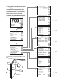

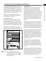
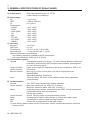
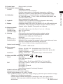
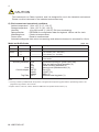
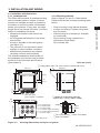
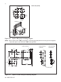
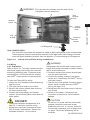
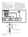
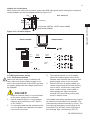
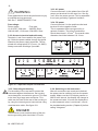
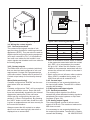
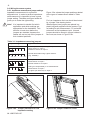
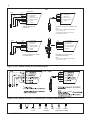
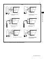
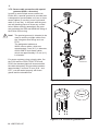
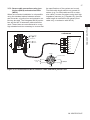
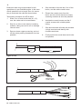
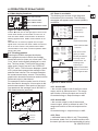
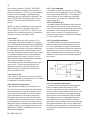

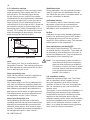
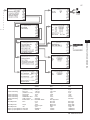
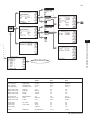
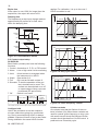
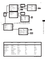
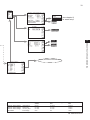
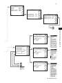
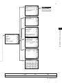
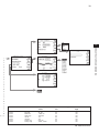
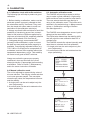
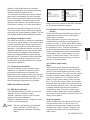
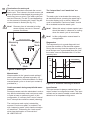
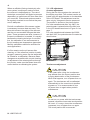
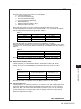
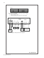
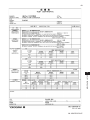

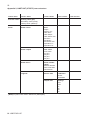
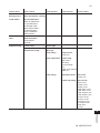
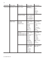
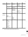
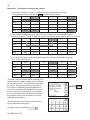
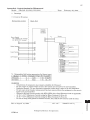

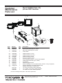
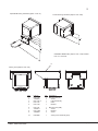
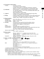
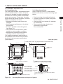
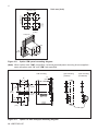
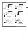
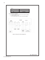
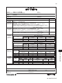
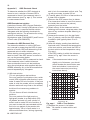


![Model SC450G [Style: S2] Conductivity](http://vs1.manualzilla.com/store/data/005772923_1-d910951678550c5451dfdc47fd4527d0-150x150.png)
![Model ISC450G [Style: S2] Inductive Conductivity](http://vs1.manualzilla.com/store/data/005904832_1-e9e6bdf8409b6fd37a184b6e2701b530-150x150.png)


![Model DO402G Dissolved Oxygen Converter [Style: S3]](http://vs1.manualzilla.com/store/data/005725233_1-bd7e4c5bf258da59a958f30153ff00ea-150x150.png)


![PH450G pH/ORP変換器[スタイル:S2]](http://vs1.manualzilla.com/store/data/006609924_2-e7299c96228b88e9d2ee8b2c0685be80-150x150.png)