1
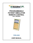
ELECTROSURGICAL UNIT
ANALYZER
ESU-2000A
USER MANUAL
BC BIOMEDICAL
ESU-2000A
TABLE OF CONTENTS
WARNINGS, CAUTIONS, NOTICES ............................................................................ ii
DESCRIPTION .............................................................................................................
1
OVERVIEW ..................................................................................................................
2
OPERATING INSTRUCTIONS ....................................................................................
3
MANUAL REVISIONS .................................................................................................... 5
LIMITED WARRANTY ................................................................................................... 5
SPECIFICATIONS ......................................................................................................... 6
NOTES ........................................................................................................................... 8
i
WARNING - USERS
The ESU-2000A is for use by skilled technical
personnel only.
WARNING - USE
The ESU-2000A is intended for testing only and
should never be used in diagnostics, treatment
or any other capacity where it could come in
contact with a patient.
WARNING - USE
Never touch exposed metal surfaces on test
leads or other current-carrying parts while the
DUT is activated.
WARNING - CONNECTIONS
All connections to patients must be removed
before connecting the DUT to the ESU-2000A. A
serious hazard may occur if the patient is
connected when testing with the ESU-2000A. Do
not connect any leads from the patient directly to
the ESU-2000A or DUT.
WARNING - MODIFICATIONS
The ESU-2000A is intended for use within the
published specifications. Any application
beyond these specifications or any unauthorized
user modifications may result in hazards or
improper operation.
ii
WARNING - LIQUIDS
Do not submerge or spill liquids on the ESU2000A. Do not operate the ESU-2000A if internal
components not intended for use with fluids may
have been exposed to fluid, as the internal
leakage may have caused corrosion and be a
potential hazard.
CAUTION - INSPECTION
The ESU-2000A should be inspected before each
use for wear and should be serviced if any parts
are in question.
CAUTION - ENVIRONMENT
Exposure to environmental conditions outside
the specifications can adversely affect the
performance of the ESU-2000A. Allow ESU-2000A
to acclimate to specified conditions for at least
30 minutes before attempting to operate it.
CAUTION - SERVICE
The ESU-2000A is intended to be serviced only
by authorized service personnel.
Troubleshooting and service procedures should
only be performed by qualified technical
personnel. Never open the ESU-2000A while
connected to the DUT, as a hazardous condition
may exist.
CAUTION - FUSE
Only replace the ESU-2000A fuse with the
specified type and rating.
CAUTION - VENTILATION
The ESU-2000A includes ventilation slots to help
prevent overheating during operation and should
not be blocked.
iii
CAUTION - CLEANING
Do not immerse. The ESU-2000A should be
cleaned by wiping gently with a damp, lint-free
cloth. A mild detergent can be used if desired.
NOTICE – SYMBOLS
Symbol
Description
Caution
(Consult Manual for Further Information)
NOTICE –ABBREVIATIONS
A
Ampere(s)
C
Celsius
°
Degree(s)
DUT
Device Under Test
FS
Full Scale
Hz
kg
lbs
Hertz
kilogram(s)
pounds
M
Mega- (10 )
MHz
Megahertz
m
milli- (10 )
6
-3
mA
milliampere(s)
mm
millimeter(s)
Ω
ohm(s)
RF
Radio Frequency
RMS
s
USA
W
Root Mean Square
second(s)
United States of America
Watt(s)
NOTICE – PERFORMING TESTS
REFER TO DUT MANUFACTURER’S SERVICE MANUAL FOR
TEST PROCEDURES AND MEASUREMENT LIMITS .
iv
NOTICE – DISCLAIMER
BC GROUP INTERNATIONAL, INC. WILL NOT BE RESPONSIBLE
FOR ANY INJURIES SUSTAINED DUE TO UNAUTHORIZED
EQUIPMENT MODIFICATIONS OR APPLICATION OF EQUIPMENT
OUTSIDE OF THE PUBLISHED INTENDED USE AND
SPECIFICATIONS.
NOTICE – DISCLAIMER
BC GROUP INTERNATIONAL, INC. RESERVES THE RIGHT TO
MAKE CHANGES TO ITS PRODUCTS OR SPECIFICATIONS AT
ANY TIME, WITHOUT NOTICE, IN ORDER TO IMPROVE THE
DESIGN OR PERFORMANCE AND TO SUPPLY THE BEST
POSSIBLE PRODUCT. THE INFORMATION IN THIS MANUAL HAS
BEEN CAREFULLY CHECKED AND IS BELIEVED TO BE
ACCURATE. HOWEVER, NO RESPONSIBILITY IS ASSUMED FOR
INACCURACIES.
NOTICE – CONTACT INFORMATION
BC BIOMEDICAL
BC GROUP INTERNATIONAL, INC.
3081 ELM POINT INDUSTRIAL DR.
SAINT CHARLES, MO 63301
USA
1-800-242-8428
1-314-638-3800
www.bcgroupintl.com
[email protected]
ESU-2000A User Manual
www.bcgroupintl.com
08/12
Copyright © 2012
Made in the USA
Rev 07
v
This Page Intentionally Left Blank
vi
BC BIOMEDICAL
ESU-2000A
ELECTROSURGICAL UNIT ANALYZER
The Model ESU-2000A is a precision Electro-Surgery Unit Analyzer (ESU). It tests the RF
power output of Electro-Surgery Units. The power reading is taken from a large 4-½ inch
analog display. It offers six resistive loads for RF power testing from 50 to 500 ohms,
along with a 200 ohm load for RF leakage current testing. The patient return electrode
resistance simulation is adjustable in one ohm increments from 0 to 999 ohms.
The following are highlights of some of the main features:
LARGE 4 ½ INCH ANALOG DISPLAY
± 2% OF FULL SCALE CURRENT ACCURACY
0-10 MHz BANDWIDTH
RETURN CONTACT MONITOR TEST
RF LEAKAGE TEST
ISOLATED OSCILLOSCOPE OUTPUT
PORTABLE
EASY OPERATION
NO BATTERIES OR POWER SUPPLY REQUIRED
STANDARD ACCESSORY KIT INCLUDED
HIGH IMPACT PLASTIC ENCLOSURE
STANDARD ACCESSORIES:
BC20 – 00120
ACCESSORY KIT (INCLUDES TEST LEADS,
ALLIGATOR CLIPS, AND REPLACEMENT FUSE)
OPTIONAL ACCESSORIES:
BC20 – 30108
SOFT CARRYING CASE
1
OVERVIEW
This section looks at the layout of the ESU-2000A and gives descriptions of the elements
that are present.
4-½ INCH
ANALOG
DISPLAY
Patient Plate Return Electrode
Monitor Test Terminals
Potentiometer
Ohms
Fast Blow
Fuse
Oscilloscope
Output
Carrying
Handle
RF Leakage
Input Terminal
ESU Ground RF
Leakage Terminal
ESM-1 Switching Module
RF Leakage Testing
or
ESU Power Testing
2
OPERATING INSTRUCTIONS
NOTICE – PERFORMING TESTS
REFER TO DUT MANUFACTURER’S SERVICE MANUAL FOR
TEST PROCEDURES AND MEASUREMENT LIMITS .
DUT RF Power Measurements
1.
Consult the DUT manufacturer’s manual for load specifications.
2.
Remove all connections between the DUT and the ESU-2000A Analyzer.
3.
Install the Switching Module on the ESU-2000A front panel so that the words “ESU
Power Testing” are right-side-up. When installed correctly, the Active Electrode
connectors should be exposed, and the RF Leakage connectors should be
inaccessible.
4.
Connect a black banana test lead from the ESU-2000A terminal labeled “Patient
Plate” to the DUT’s Patient Plate or Return Electrode. (Note: In some instances, the
DUT’s Return Electrode may need to be shorted together to enable RF output)
5.
Connect a red banana test lead from the DUT’s RF Active Output to the desired
load terminal of the ESU-2000A. The Active Electrode input connectors are color
coded, and each corresponds to a color-coded range on the analog meter.
6.
Set the DUT for proper output mode and power level, being careful that the power
setting does not exceed the full-scale Power range selected on the ESU-2000A.
7.
Activate the DUT output. The Analyzer will indicate both mA RMS and Power (W)
on the appropriate color-coded wattage meter range.
8.
Deactivate the DUT output before disconnecting from ESU-2000A, or before moving
the Active Electrode test lead to a different input range connector.
DUT RF Leakage Current Measurements
1.
Remove all connections between the DUT and the ESU-2000A Analyzer.
2.
Install the Switching Module on the ESU-2000A front panel so that the words “RF
Leakage Testing” are right-side- up. When installed correctly, the Active Electrode
connectors should be inaccessible, and the RF Leakage connectors should be
exposed.
3.
Connect a red banana test lead from the ESU-2000A terminal labeled “RF Leakage”
to the DUT’s RF Active Output. DO NOT MEASURE ACTIVE ELECTRODE
LEAKAGE ON NON-ISOLATED ESUs with the ESU-2000A. Damage may occur to
3
the ESU-2000A.
4.
Connect a green banana test lead from the ESU-2000A terminal labeled “EARTH”
to the DUT’s Earth Ground. If no accessible Earth Ground point exists on the DUT,
it is acceptable in most cases to use Receptacle Earth.
5.
Set the DUT for proper output mode and power level.
6.
Activate the DUT output. The Analyzer will indicate the RF Leakage current from
the DUT Active Electrode on the color-colored RF Leakage scale.
7.
Deactivate the DUT output.
8.
Repeat Active Output RF Leakage Testing for all available Output Modes and
Output Electrodes as called for in the DUT Leakage Test Procedures.
9.
Move the red test lead from the DUT’s RF Active Output to the DUT’s Patient Plate
or Return Electrode. (Note: In some instances, the DUT’s Return Electrode may
need to be shorted together to enable RF output)
10. Set the DUT for proper output mode and power level.
11. Activate the DUT output. The Analyzer will indicate the RF Leakage current from
the DUT Active Electrode on the color-colored RF Leakage scale.
12. Deactivate the DUT output.
13. Repeat Return Output RF Leakage Testing for all available Output Modes and
Output Electrodes as called for in the DUT Leakage Test Procedures.
DUT Patient Plate or Return Electrode Monitor Test
1.
Remove all connections between the DUT and the ESU-2000A Analyzer.
2.
Connect two banana test leads from the ESU-2000A terminals labeled “PATIENT
PLATE” to the DUT Patient Plate or Return Electrode. If it is not possible to simply
connect to the DUT Patient terminals directly, there exists an alternate method to
fashion this connection as follows.
a. Acquire a DUT-compatible Disposable Split-Pad Return Electrode as would
be used for a patient.
b. Cut off the Adhesive Split-Pad from the cord, then strip each individual wire.
c. Using the Alligator clips supplied in the ESU-2000A standard accessory kit,
connect each banana test lead from the ESU-2000A to the individual wires of
the Split-Pad Return Electrode.
d. Plug the fashioned return electrode into the DUT Patient Plate or Return
Electrode Connection.
3.
Adjust ESU-2000A Patient Plate Resistance as necessary to verify DUT Patient
Plate or Return Electrode Monitor mode as specified by the DUT manufacturer.
4
MANUAL REVISIONS
Revision #
Revisions Made
Rev 01
Rev 02
Rev 03
Rev 04
Rev 05
Rev 06
Rev 07
New Manual Format
Accessory Fuse Updated
Notices Updated
Specifications Updated
Format Updated, Misc. Edits
Format Updated
Specifications Updated
LIMITED WARRANTY
WARRANTY: BC GROUP INTERNATIONAL, INC. WARRANTS ITS NEW PRODUCTS TO BE FREE
FROM DEFECTS IN MATERIALS AND WORKMANSHIP UNDER THE SERVICE FOR WHICH THEY
ARE INTENDED. THIS WARRANTY IS EFFECTIVE FOR TWELVE MONTHS FROM THE DATE OF
SHIPMENT.
EXCLUSIONS: THIS WARRANTY IS IN LIEU OF ANY OTHER WARRANTY EXPRESSED OR
IMPLIED, INCLUDING, BUT NOT LIMITED TO ANY IMPLIED WARRANTY OF MERCHANTABILITY
OR FITNESS FOR A PARTICULAR PURPOSE.
BC GROUP INTERNATIONAL, INC. IS NOT LIABLE FOR ANY INCIDENTAL OR CONSEQUENTIAL
DAMAGES.
NO PERSON OTHER THAN AN OFFICER IS AUTHORIZED TO GIVE ANY OTHER WARRANTY OR
ASSUME ANY LIABILITY.
REMEDIES: THE PURCHASER'S SOLE AND EXCLUSIVE REMEDY SHALL BE: (1) THE REPAIR OR
REPLACEMENT OF DEFECTIVE PARTS OR PRODUCTS, WITHOUT CHARGE. (2) AT THE OPTION
OF BC GROUP INTERNATIONAL, INC., THE REFUND OF THE PURCHASE PRICE.
P:\MANUALS\BCGroup\…\ESU-2000A\ESU-2000A_UM_Rev07.doc
5
SPECIFICATIONS
RF MEASUREMENT
RANGE
ACCURACY
CURRENT
0 to 1000 mA RMS
POWER
0 to 500 W
CURRENT
± 2% FS
POWER
± 5% FS
FREQUENCY
0 to 10 MHz
FUSE
500 mA Fast-Blow FWH-1/2
OSCILLOSCOPE OUTPUT
OUTPUT
Isolated
Uncalibrated
CONNECTION
BNC (50 Ω)
VALUES
50 Ω
100 Ω
200 Ω
300 Ω
400 Ω
500 Ω
TYPE
Non-Inductive
ACCURACY
± 2% ± 1 Ω
VARIABLE LOAD
POWER RATING
(MAX)
LEAKAGE LOAD
50 Ω
50 W
100 Ω
100 W
200 Ω
200 W
300 Ω
300 W
400 Ω
400 W
500 Ω
500 W
DUTY CYCLE
10 seconds on, 20 seconds off
VALUE
200 Ω
TYPE
Non-Inductive
ACCURACY
± 2% ± 1 Ω
POWER RATING
50 W
CONNECTIONS
4 mm Banana
6
RETURN ELECTRODE MONITOR TEST LOAD
RANGE
0 to 999 Ω
RESOLUTION
1 Ω
ACCURACY
± 3% + 3 Ω
CONNECTIONS
4 mm Banana
PHYSICAL & ENVIRONMENTAL
DISPLAY
CONSTRUCTION
4-1/2” Analog Meter
Color-coded display (W and mA)
ENCLOSURE
ABS Plastic
FACE PLATE
Back-printed Lexan
SIZE
5.36 x 8.68 x 9.10 Inches
(136.1 x 220.5 x 231.1 mm)
WEIGHT
≤ 4 Lbs (1.82 kg)
OPERATING RANGE
15 to 30 °C (59 to 86 °F)
20 to 80% RH, Non-Condensing
STORAGE RANGE
-40 to 60 °C (-40 to 140 °F)
7
NOTES
8
NOTES
9
NOTES
10
BC GROUP INTERNATIONAL, INC.
3081 ELM POINT INDUSTRIAL DRIVE
ST. CHARLES, MO 63301
USA
1-800-242-8428
1-314-638-3800
www.bcgroupintl.com
[email protected]
ESU-2000A User Manual
08/12 – Rev 07
Copyright © 2012
Made in the USA