1
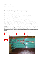
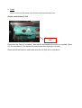
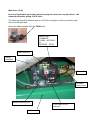
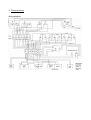
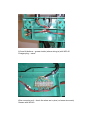
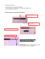
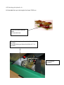
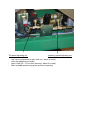
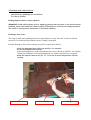
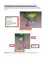
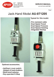
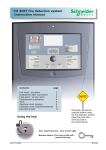
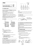
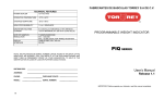
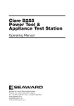
SERVICE MANUAL FOR HAICO TABLES 12/2005
Checking list for Haico Telgte series surgery tables:
Overall checking
1. Battery condition
2. Fuses
3. Electical wiring
4. Side panel hydraulic arms
5. Hydraulic system
6. Paddings / Rubber bellows
7. Wheels
8. Accessories
Overall checking
-
visually check that the table is in working condition, so that al parts (side panels,
hydraulic arms, handles, etc. are in proper condition. Especially look for bend parts etc.
also look that there is no especially corroted places.
1. Battery condition
- follow the instructions below
Measuring the battery and the charger voltage:
Disconnect the charger from the table.
Check first the battery voltage by using a normal voltmeter, 12V DC area.
An example : the voltage is 11,8 V
Then connect the charger to the table and check again the voltage.
If the voltage is the same ( 11,8V) the battery is not in contact with the charger .
If the voltage now increases clearly over 11,8V it shows that charging works.
If after overnight charging the battery do not work properly it is damaged and must be
replaced.
NOTE! Check the voltage not before than one hour after disconnecting the charger
that the battery voltage first normalizes and measuring result is accurate .
The normal voltage in full battery is 12,5 to 12,7 volts.
The measuring result under 12 volts indicates that service life of the battery is
ending.
First from the fuse side pole
Fuse
Second from the fuse side +
pole
AND/OR
Checking the battery condition:
Using a multimeter, measure the battery terminal voltage in the table outlet box between
number one and ground terminals.
1 = battery positive (+)
terminal
Ground = battery (-) negative
terminal
Lookcarefully,
small signs.
Control circuit
fuse
A reading of 12.7 V or over means that the battery is fully charged.
A reading of 11 V indicates the need for immediate charging. The red indicator light at the
back of the table should be glowing.
A reading of under 7 V means that the battery is almost empty. In this case, even the red
indicator light at the back of the table does not have enough power to glow.
A reading of 0 - 4 volts means that the battery is empty. In this case, the automatic charger
is no longer able to recharge because it needs a minimum of 4 volts to function.
2. Fuses
-
there is 2 fuses in the system, the circuit control fuse and main fuse
Circuit control fuse (2.5 A)
Control circuit
fuse
Check that the fuse is in condition, also that the fuse holder is not dirty or corroted, (there
is 2 thin contactors in the holder and sometimes they might get corroted)
Clean and oil the fuse box and holder with thin oil (WD-40 or equivalent)
Main fuse (50 A)
In case of total black-out in the hydraulic pump the main fuse may be broken…the
solenoid still works giving CLICK voice.
The table top should be lifted at least up to 50-60 cm height in order to acces the main
fuse from the table side.
Open the rubber bellows from the FUSE-side.
Battery type :
FIAMM-GS
YUASA NPC38-12
or
ENERGIE WP50-
Main fuse 50A
Lifting
mechanis
Solenoid
Hydraulic
pump motor
Battery fastening bar
Front relay for the
solenoid
Undercarria
3. Electrical wiring
Wiring diagram
Lift and tilt buttons – grease inside (where wiring is) with WD-40
Charger plug – same
Wire connector rod – check the wires are in plce (no loose wire ends)
Grease with WD-40
4. Side panel gas springs
-
-
check that they are not bend and corroted
use oil ( hydraulic- / motoroil) when oiling the gas springs inside
not necessary need to take off
the high pressure hydraulic gas cylinder:
Free movement
Minimum slack gap in the
level is 2 mm
Parts of the hydraulic gas cylinder
The adjusting and lock screw
Put oil from the little hole on the
opposite side of the handle !
ATTENTION! Handle the high pressure cylinder
with care! Never do not try to open it!
5. Hydraulic system
-
check any leagage etc. inside the table (when rubber belows is open)
-
if need to do adjustments follow the instructions below;
OPT/checking the hydraulic oil…
Lift the table first up to the height of at least 70-80 cm.
Open the rubber bellows
here
or from the front
The table being down there should be oil ¾ in
the tank.
The table being up there should be oil ¼ in
the tank.
The hydraulic
pressure
Tilt speed adjusting nut
-
Lowering speed adjusting nut
use 2 mm hex wrench to open lock nut ( same on both )
close the adjusting nut totally
open it little (tilt – 1/6 or less, lowering– about 2 rounds )
find a suitable speed varying the amount of opening
6.Paddings and rubber bellows
-
check that the paddings are not broken
if so do as follows;
Damaged panel surface can be repaired.
Attention! Avoid making sharp cuts or applying great pressure points in the surface panel
padding, which can break the rubber coating. Several hours of continuous sharp pressure
can result in a permanent depression in the panel padding.
If damage does occur:
The surgery table panel padding material is impermeable to water, therefore it does not absorb
moisture even when the polyurethane surface coating is damaged.
Possible damage to the surface coating can easily be repaired as follows :
- clean the damaged area with pure alcohol, for example
- dry the damaged area carefully
- repair the damaged area with polyurethane glue such as Wurth or Sikaflex, for example.
Contact the distributor or the manufacturer in case further instructions are required.
- allow the repaired area to dry for 15 - 20 hours at room temperature, before
reusing.
Area to be repaired
Glue cartridge
Glue gun
7. Wheels (when checking the following oil the bearings with motor oil or WD-40)
Brake holding capability diminishes with time. Therfore, check the condition of the brakes
and adjust them as necessary. Brake adjustment is done simply by tightening the adjusting
screw.
A 13 mm boxend wrench
is needed for the
adjustment.
Turn the screw
approximately
1/4 - 1/2 turns clockwise,
test the brake and readjust
if necessary.
Zink plated wheel
Looser
Tighter
Use 22 mm
fork wrench
Stainless steel wheel
Attention! Do not overtighten the adjusting screw, it will hinder the locking action.
8. Accessories
-
check that all the accessories does exist (clamps, bands, leg support parts, etc.)
check every item that they are in proper condition
do necessary adjustments/repairings