1
RS160 and RS220
INTRODUCTION
This service manual is intended as a reference for
the installer, user, and service agent of this
Scotsman Refreshment Stand. It includes the
necessary information to install, start up, operate,
clean and maintain this unit.
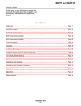
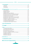
TABLE OF CONTENTS
SPECIFICATIONS . . . . . . . . . . . . . . . . . . . . . . . . . . . . . . . . . . . . 2
FOR THE INSTALLER: Installation Of Loose
Shipped Parts . . . . . . . . . . . . . . . . . . . . . . . . . . . . . . . . . . . . . . 3
FOR THE INSTALLER: Tubing Installation . . . . . . . . . . . . . . . . . . . . . . . 4
FOR THE INSTALLER: Sealing of Cabinet . . . . . . . . . . . . . . . . . . . . . . . 5
FOR THE INSTALLER . . . . . . . . . . . . . . . . . . . . . . . . . . . . . . . . . . 6
Installation: Scotsman CM Cuber . . . . . . . . . . . . . . . . . . . . . . . . . . . . 7
Installation: Scotsman Slim Line Cuber . . . . . . . . . . . . . . . . . . . . . . . . . 8
SODA SYSTEM SCHEMATIC: 6 Valve Units . . . . . . . . . . . . . . . . . . . . . . 9
SODA SYSTEM SCHEMATIC: 8 Valve
Units . . . . . . . . . . . . . . . . . . . . . . . . . . . . . . . . . . . . . . . . . . . 10
HOW IT WORKS . . . . . . . . . . . . . . . . . . . . . . . . . . . . . . . . . . . . . 11
INITIAL START UP
. . . . . . . . . . . . . . . . . . . . . . . . . . . . . . . . . . . 12
FOR THE OPERATOR . . . . . . . . . . . . . . . . . . . . . . . . . . . . . . . . . . 13
CLEANING AND SANITIZING
. . . . . . . . . . . . . . . . . . . . . . . . . . . . . 16
SANITIZING SYRUP SYSTEM . . . . . . . . . . . . . . . . . . . . . . . . . . . . . 18
SERVICE DIAGNOSIS . . . . . . . . . . . . . . . . . . . . . . . . . . . . . . . . . . 19
SERVICE DIAGNOSIS . . . . . . . . . . . . . . . . . . . . . . . . . . . . . . . . . . 20
ELECTRICAL SEQUENCE . . . . . . . . . . . . . . . . . . . . . . . . . . . . . . . 21
MOVING . . . . . . . . . . . . . . . . . . . . . . . . . . . . . . . . . . . . . . . . . 22
REMOVAL & REPLACEMENT
. . . . . . . . . . . . . . . . . . . . . . . . . . . . . 22
This manual contains important information, read it before installation or operation.
Keep it for future reference.
It marks important safety information on a hazard
that might cause serious injury.
June 1995
Page 1
RS160 and RS220
SPECIFICATIONS
The term “Refreshment Stand” means a machine
that stores ice in an insulated, sanitary container;
upon demand it dispenses that ice into a cup or
glass; it cools beverages using ice falling from the
hopper onto a cold plate at the base of the hopper;
and it dispenses beverages via post-mix or pre mix
valves. Some of the valves are not carbonated;
they may be changed to carbonated if desired.
Power to operate the valves may be shut off by a
key switch.*
* Premix is not electrically powered.
The RS requires additional equipment to be
functional:
An ice machine or source of sanitary ice; a
carbonator for post mix (and potable water); a
syrup delivery system, either pressurized syrup
cans or bag-in-a-box; and CO2. The dispenser
must also be connected to a drain.
NOTE: This Refreshment Stand is designed to
dispense cubed ice only. Flaked or Nugget ice
will not work.
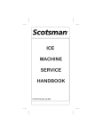
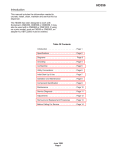
RS160 SHOWN,
RS220 SIMILAR
BUT 30" WIDE
Base
Width
Model
RS160
22"
RS220
30"
Rotor motor is 1/10 HP.
Total Ice Storage
Capacity
160 lb.
220 lb.
Basic Electrical
Amperage
Power Cord
115/60/1
115/60/1
2 amps
2 amps
4’ with plug
4’ with plug
Options: Fast flow carbonator (100 G.P.H.). May be obtained as push button actuation for ice and soda or
lever actuation for ice & soda. Both are factory installed. Various brand standard or fast flow post-mix
valves are available (factory installed). Also available in premix with Booth Capre valves only (factory
installed).
Cubed ice machines may be stacked onto the top of the dispenser with an adapter kit:
• RS160: Scotsman cubers SLE300, SLE400 or SLE400R use kit # KADUN2.
• RS220: Scotsman cubers CME250, CME256, CME500, CME506, CME650 OR CME656 use kit #
KADCM2.
Scotsman Drink Systems are designed and manufactured with the highest regard for safety and
performance. They meet or exceed the standards of U.L. and N.S.F.
Scotsman assumes no liability or responsibility of any kind for products manufactured by Scotsman that
have been altered in any way, including the use of any parts and/or other components not specifically
approved by Scotsman
Scotsman reserves the right to make design changes and/or improvements at any time. Specifications and
designs are subject to change without notice.
June 1995
Page 2
RS160 and RS220
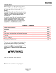
FOR THE INSTALLER: Installation Of Loose Shipped Parts
Several components are packed inside the hopper:
• Drip tray and grill
• 2 drain hoses
• Several hose clamps
• Several barbed hose fittings
• Fluorescent tube
• Lever (for lever models)
Remove them and set them aside for installation.
ICE CHUTE
MOUNTING
PANEL
Ice lever/Ice Chute/Fluorescent Tube
1. Lift up and pull out to remove upper front panel.
2. Slide out ice chute mounting panel.
3. Insert the ice lever in to the valve panel through
the slot as shown.
4. Swing the ice lever through from right to left and
let it hang freely.
5. Twist the fluorescent tube into the sockets.
6. Replace ice chute mounting panel.
7. Insert clear ice chute into the panel and twist
clockwise 1/3 turn.
8. Replace the upper front panel.
RS160 TOP VIEW
(For Reference)
June 1995
Page 3
ICE CHUTE
Install Lever
In Slot
RS160 and RS220
FOR THE INSTALLER: Tubing Installation
1. Locate the dispenser on the counter. Allow
vertical clearance above unit for the removal of the
cover, and for pouring ice into the hopper.
Drip Tray/Grill
1. Remove splash panel from unit.
Note: If installing an ice cube machine on top,
check for proper total cabinet clearance, including
adapter kit.
2. Connect the sink drain hose to the sink drain
fitting and secure it with a hose clamp. Route the
tube to the building drain. Follow all local plumbing
codes.
The syrup and carbonated water connections need
to be made at the cold plate’s stub lines. The cold
plate stub lines are behind the splash panel.
4. Hang the drip tray onto the metal tabs on the
base of the unit.
Tubing routing to the cold plate is from either the
back of the unit, or through openings in the base.
A plumbing circuit schematic diagram is on the
back of the cabinet, refer to it for cold plate
connections.
2. Plan the routing of the tubing (drain and soda).
5. Replace the splash panel.
Note: If the cabinet has been sealed to the
countertop, add sealant around the sink and
counter top to provide a seal with a radius of 1/2".
Follow the sealant manufacturer’s instructions on
the package for working with the sealant, and
cleaning up.
If the tubing will pass through the base, a hole
in the counter top must be made prior to
sealing the unit to the counter.
SIDE VIEW OF DRIP TRAY INSTALLATION
The tubing may also be routed through the back.
3. Connect the drain system. There are two drains
to connect: The sink (or drip tray) drain and the
cold plate drain. They must be routed separately.
The tubes may drain the unit through the back or
through the openings in the base.
The cold plate drain tube is the one with the foam
insulation on it. Tilt or lift the unit to expose the
bottom of the dispenser.
DRIP TRAY
DRAIN TUBING
DRAIN
FITTING
Cold Plate
Drain
Connection
HOSE
CLAMP
Bottom View of
Dispenser
SPLASH
PANEL
Sink Drain Connection
DRAIN TUBING
DRIP TRAY
Connect the threaded drain fitting (packed loose in
the hopper) to the cold plate drain connection.
Connect the cold plate drain tube to this fitting,
route the hose to the building drain.
Install the sink drain after the machine has been
set in place.
MOUNTING TABS
June 1995
Page 4
RS160 and RS220
FOR THE INSTALLER: Sealing of Cabinet
In order to comply with National Sanitation
Foundation (NSF) requirements, this unit must be
either elevated above the counter top sufficiently to
provide space for cleaning under the unit or
sealed to the counter top.
THE CABINET MUST BE
LEVELED LEFT TO RIGHT AND
FRONT TO BACK
Elevating the unit may be accomplished by using
the leg kit. Legs screw into threaded holes in the
base of the unit.
If the unit is to be sealed to the counter top, the
soda tubing installation should be planned such
that its connections may be finished after the unit
has been sealed to the counter.
Seal the unit by the use of room temperature
vulcanizing (RTV) rubber sealant such as General
Electric IS 808 Industrial Sealant, Dow Corning
731 or the equivalent.
With the unit located on the counter as desired:
A. Tilt or lift the unit to expose the bottom flanges
of the base frame.
B. Apply the sealant to cover the bottom flanges of
the base frame.
C. Return the unit to the desired position on the
counter top.
D. Add sealant around the base frame and counter
top to provide a seal with a radius of 1/2". Follow
the sealant manufacturer’s instructions on the
package for working with the sealant, and cleaning
up.
E. Seal around all access holes in the counter top
with Permagum or Mortite caulk or an equivalent
material.
June 1995
Page 5
USE LEGS OR
SEAL TO
COUNTERTOP
RS160 and RS220
FOR THE INSTALLER
1. If installing a carbonator, locate it nearby.
2. Route the drain lines to the building drain. Vent
the drain tubes if installing at the back of the
cabinet.
3. Locate electrical supply (for cord - 115v outlet).
The outlet must be properly grounded. The
circuit must be fused and no other electrical
appliance should be on the circuit.
ALL ELECTRICAL WIRING MUST CONFORM
TO NATIONAL AND LOCAL CODES
4. Remove splash panel.
Refer to the plumbing schematic on the back of
the cabinet (all stub lines are labeled) and:
A. Connect carbonated water supply lines (field
supplied) from the remote carbonator to the
carbonated water stub line at the dispenser cold
plate.
B. Connect water supply lines (field supplied)
from building source to carbonator (filtered water
is recommended).
C. Connect water supply line(s) to the plain
water stub line(s) on the cold plate for use with
the non-carbonated valve.
NOTE: If ALL valves need carbonation, connect
an additional carbonated water line from the
carbonator to the plain water stub line on the
cold plate.
D. Connect syrup lines from the syrup supply to
the cold plate syrup stub lines.
Typical Installation
Cold
Plate
Stub
Lines
Back Plumbing
Cover Plate
Sink and
Cold Plate
Drain Tubes
Remove Splash
Panel and Sink
Beverage &
Water Tubes
6. Connect primary CO2 regulator to CO2 tank.
Secure secondary regulators to wall or other
stationary surface.
7. Connect CO2 line between outlet of primary
regulator and inlet of secondary regulators.
8. Connect CO2 lines between outlets of
secondary regulators and syrup tanks. Or to syrup
pumps in the case of Bag-In-Box.
June 1995
Page 6
RS160 and RS220
Installation: Scotsman CM Cuber
1. Make sure the counter the dispenser is placed
on is structurally able to hold the combined weight
of the dispenser, ice and ice machine.
2. Install the dispenser.
3. Remove the dispenser cover (save it - it will be
needed if the ice machine is removed).
4. Place stainless steel adapter sleeve onto the
top of the dispenser.
5. Using the tube of sealant from the kit, place a
bead of sealant onto the top edges of the area on
the adapter where the ice machine will go.
6. Place a bead of sealant onto the inside and
outside seams where the dispenser and adapter
meet.
7. Using a mechanical lift, hoist the ice machine
onto the dispenser, center left to right and align
flush to the back.
8. Install a bin thermostat bracket assembly onto
the underside of the CM ice machine.
Note: Thermostat bracket only required by CM250,
CME250, CM500, CME500, CM650 or CME650.
9. Fasten together at the back of the machine
using bolts from the ice maker and mounting
straps from the kit.
10. Place the front cover plate onto the dispenser
in front of the ice machine.
June 1995
Page 7
RS160 and RS220
Installation: Scotsman Slim Line Cuber
Assembly:
The assembly of the ice machine onto the
dispenser requires two additional parts: an adapter
and a thermostat stand off kit.
1. Mark two spots on the inside left liner of the
dispenser: 2" down from the top, 4" from the back,
and 4" apart.
2. At the two marked spots, drill two 1/4" holes thru
the plastic liner only.
3. From the stand off kit, locate the stand offs and
plastic anchors. Thread the stand offs partially into
the plastic anchors.
4. Push the anchors/stand offs into the holes
5. Screw the stand offs all the way into the
anchors. Be sure that the holes in the stand offs
are horizontal.
6. Place a bead of silastic (from the kit) around the
stand offs.
7. From the adapter kit, place the stainless steel
adapter onto the top of the dispenser. Follow all
directions included with the kit.
8. After the ice machine has been placed on the
dispenser, remove the front panel and uncoil all of
the bin thermostat capillary tube.
9. Route the capillary tube thru the front hole in the
base of the ice machine, to the left side if the
dispenser towards the stand offs.
10. Route the end of capillary tube thru the
stand-offs, bend the tube around the stand offs so
that it does not fall off.
11. Check that the routing of the capillary tube is
away from the ice chute and up high enough near
the base of the ice machine.
June 1995
Page 8
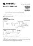
CO2
SUPPLY
CARBONATOR
TANK
WATER SUPPLY
COLD PLATE
SYRUP TANKS
SODA VALVES
C C
6
Carb.
W
5
W
4
Non Carb
1
3
2
3
2
4
5
Carbonated
1
6
RS160 and RS220
SODA SYSTEM SCHEMATIC: 6 Valve Units
June 1995
Page 9
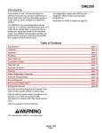
CO2
SUPPLY
CARBONATOR
TANK
WATER SUPPLY
COLD PLATE
SODA VALVES
1
8
2
Carb.
3
4
7
6
7
5
SYRUP TANKS
5
6
Non Carb
8
4
W
W W
3
C
2
C
Carbonated
1
RS160 and RS220
SODA SYSTEM SCHEMATIC: 8 Valve Units
June 1995
Page 10
RS160 and RS220
HOW IT WORKS
The ice is stored in a hopper, and the hopper is
sloped towards the front of the dispenser. At the
front there is an angled rotor, when that rotor turns
it scoops ice up, lifts it to the top of the ice chute
and drops it through that chute into the user’s
container.
At the base of the hopper is a cold plate (a block of
aluminum with several circuits of stainless steel
tubing molded within it). Ice in the hopper is in
contact with the cold plate and causes the
beverages within the tubing to become chilled.
The ice in direct contact with the cold plate is not
dispensed.
Cut Away View
Ice
Ice Sweep
Rotor
Ice On Cold
Plate
Door
Upper Ice
Chute
Ice Chute
Cold Plate
June 1995
Page 11
RS160 and RS220
INITIAL START UP
1. Turn on the CO2.
15. Leave the unit alone for about a half hour to
cool the cold plate and soda product.
2. Set the high pressure regulator (to the
carbonator) to 80-100 PSI.
3. Set the low pressure regulator to 40-50 psi. Set
diet regulator (if used) to 10-15 psi.
4. Turn on the water to the carbonator.
5. Plug in or turn on the carbonator.
6. Purge CO2 gas pressure from the carbonator
tank once or twice while it is filling by pulling up on
the pressure relief valve on the top of the tank.
7. Sanitize the ice storage system as instructed on
page 16.
8. Turn the key switch to ON.
Ice hopper contains parts
that can move at any
time and will cause injury
if hands are in the way.
Do not remove cover
until the unit has been
unplugged from electrical
power.
16. While waiting, check all connections for leaks,
repair as required.
17. When cold plate has cooled, adjust each soda
valve for the proper water to syrup ratio.
To remove valve covers:
• Lift up and pull out to remove upper front panel.
• Twist clear ice chute 1/3 turn counterclockwise
and pull down to remove.
• Slide ice chute mounting panel forward to
remove from cabinet. Valve covers may now be
removed. Reverse to reassemble when valves
are adjusted.
Note: there is a timer in the control box that will
activate the rotor in the ice bin every two hours.
The amount of time that the rotor turns is
adjustable between one tenth of a second and 4
seconds. The purpose for the timer is to agitate the
ice to keep it from fusing together after long
periods in the bin.
To Access Soda Valve Covers
9. Fill hopper with sanitary ice.
10. Plug the unit’s power cord into an electrical
outlet, the lighted sign should come on. Dispense
several containers of ice.
Ice Chute
Mounting
Panel
11. Activate soda valves until water is dispensed.
12. Check the primary CO2 gauge for the
carbonator, and the secondary CO2 gauge for the
syrup.
13. Connect the syrup containers to the soda
system.
14. Activate the soda valves until syrup is
dispensed with the water.
Ice Chute
June 1995
Page 12
RS160 and RS220
FOR THE OPERATOR
This section covers operating controls, daily
pre-operation check, unit operation, adjustments,
replenishing CO2 and syrup supplies, and daily
cleaning.
OPERATING CONTROLS - Units have either
levers or push buttons
General Information
Dispensing Soda: To minimize foaming, a cup, 1/3
full of ice, should be filled at an angle so that the
product runs down the inside wall of the cup, until
the cup is nearly full.
Levers: Dispensing valve levers, located below
the dispensing valves, need only to be pressed
with a cup or glass to dispense product.
When the ice dispense lever or button is pushed, a
motor begins to turn the rotor in the hopper, and a
solenoid opens the ice chute door. Ice is then
dropped down through the ice chute.
Ice: Ice will continue to be dispensed for as long as
the lever is held in, or until the hopper is empty.
NOTE: Periodically during the day, clean up the ice
spilled in the drip tray.
Push Buttons: On the front of each valve will be a
button, that when pushed, will activate the valve.
Ice: When the ice dispense button is pushed, ice
will be dispensed for as long as the button is held
in or until the hopper is empty.
There is a timer in the control box that will activate
the rotor in the ice bin every two hours.
No ice will fall out because the ice chute door will
remain closed. The amount of time that the rotor
turns is factory set at 2 seconds, and is adjustable
between one tenth of a second and 4 seconds.
The reason for the timer is to stir the ice so that it
doesn’t fuse together after long periods in the bin.
Cover
Front Panel
Soda Valves
Ice Chute
Splash
Panel
Drip Tray
Ice Dispense Lever
June 1995
Page 13
RS160 and RS220
FOR THE OPERATOR
Daily Check
1. Make sure that the CO2 cylinder primary
regulator assembly 1800 psi gauge is not in the
shaded ("change CO2 cylinder") portion of the dial.
If so, CO2 cylinder is almost empty, and must be
replaced.
2. Sufficient syrup supply in all syrup containers. If
not, replenish syrup supply.
The dispenser must always contain ice to have ice
available for use, and to keep the syrup product
cool. If there is no ice in the hopper, it will take
about 1/2 hour after ice is added for the cold plate
to cool off properly.
NOTE: After ice is loaded into a WARM hopper,
dispense several containers of ice: this helps
disperse the ice across the cold plate.
Keep the cover in place, and check the ice supply
regularly during operating hours.
3. Make sure drip tray and grill are clean.
4. Make sure soda valve nozzles are clean.
6. Keep drip tray clear of spilled ice
5. Remove cover and pour sanitary ice into the
hopper.
7. At the end of the day:
Remove soda valve nozzles and diffusers, clean
them and soak in hot water.
Ice hopper contains parts
that can move at any
time and will cause injury
if hands are in the way.
Do not remove cover
until the unit has been
unplugged from electrical
power.
Remove the grill from the drip tray, clean the drip
tray, grill and splash panel, make sure the drain is
open by pouring hot water into the drip tray. Return
the grill to the drip tray.
Pour Hot Water Down Drip
Tray Every Day
Do NOT use bagged ice directly from a freezer.
The ice must be broken up in the bags first before
adding to the hopper.
Large chunks of ice can NOT be dispensed.
To avoid a delay in cooling soda at the beginning
of the business day, make sure that the hopper is
kept at least 1/4 full of ice to keep the cold plate
(and the soda product) cold overnight.
June 1995
Page 14
RS160 and RS220
FOR THE OPERATOR
Replenishing CO2 Supply
Note: When indicator on CO2 cylinder regulator
1800 psi gauge is in the shaded area, the cylinder
is almost empty and should be changed.
7. Check CO2 connections for leaks. Tighten loose
connections.
1. Fully close (clockwise) CO2 cylinder valve.
2. Slowly loosen CO2 regulator assembly coupling
nut allowing CO2 pressure to escape, then remove
regulator assembly from CO2 cylinder.
3. Unfasten safety chain and remove empty CO2
cylinder.
If the CO2 tanks falls
over, valve can
become damaged or broken off, this can
cause serious injury.
To avoid personal injury and/or property damage,
always secure CO2 cylinder with a safety chain to
prevent it from falling over.
4. Position CO2 cylinder and secure with safety
chain.
6. Open (counterclockwise) CO2 cylinder valve
slightly to allow lines to slowly fill with gas, then
open valve fully to back seat valve. (Back seating
valve prevents leakage around valve shaft.)
Replenishing Syrup Supply.
1. Remove CO2 disconnect and syrup disconnect
from empty syrup tank, then remove tank.
2. Place full syrup tank in position, then connect
CO2 disconnect and syrup disconnect to full syrup
tank.
Syrup Flavor Change.
Contact beverage supplier to have soda circuit
sanitized.
5. Make sure gasket is in place inside CO2
regulator coupling nut, then install regulator on
CO2 cylinder.
June 1995
Page 15
RS160 and RS220
CLEANING AND SANITIZING
The drip tray, grill and splash panel area
should be cleaned daily.
Weekly:
Clean valve nozzles & diffusers:
The soda valve nozzles and diffusers should
be cleaned weekly.
Looking down from the top of the unit, turn the
nozzle clockwise about 1/8 turn; pull down to
remove it.
The ice storage system should be sanitized
monthly.
Pull down to remove the diffuser.
Daily:
Clean both with soap and water, rinse with potable
hot water. Replace on the valve.
1. Lift up and remove grill from drip tray.
2. Use mild soap, hot water, and a clean cloth to
wash drip tray and splash panel; rinse with hot
water, allowing plenty of hot water to run down the
drain.
BOOTH VALVE
3. Wash the grill, then rinse with clean water. Place
back in drip tray.
4. Clean all exterior surfaces of the unit with warm
water and a sponge. Rinse out the sponge with
clean water, wring excess water out of the sponge,
and wipe off external surfaces of the unit. Wipe
unit with a clean soft cloth. Do NOT use abrasive
type cleaners.
CORNELIUS VALVE
Pour Hot Water Down
Sink Every Day
Diffuser or
Baffle
Nozzle
DOLE VALVE
June 1995
Page 16
RS160 and RS220
CLEANING AND SANITIZING
Monthly/Initial Start Up:
5. Using a clean cloth or sponge, wipe all interior
surfaces of the ice storage hopper with the
sanitizing solution, allow to air dry.
Sanitize the Ice Storage System.
Note: this should only be done by qualified
personnel.
6. Wipe all surfaces of the rotor with the sanitizing
solution, and allow to air dry.
1. Unplug the Refreshment Stand’s electrical cord
from the electrical power.
7. Pull out and remove the upper front panel.
A. Twist the clear ice chute 1/3 turn, and pull down
to remove.
Ice hopper contains parts
that can move at any
time and will cause injury
if hands are in the way.
Do not remove cover until
the unit has been
unplugged from electrical
power.
2. Remove cover and
discard all remaining ice
Sweep Arm
Rotor
3. Mix a solution of 1
ounce of household
bleach to 2 gallons of
potable water, or: mix
a solution of any
approved sanitizer,
following the
directions for mixing
and applying that
sanitizer.
4. Unscrew the sweep
arm from rotor shaft,
and pull the rotor from
hopper.
Clear Ice
Chute
B. Locate the two thumb screws holding the upper
ice chute; remove them (1 on top and 1 below).
Remove the upper ice chute from the machine.
Thoroughly wipe the surfaces of the bin door and
both ice chutes with the sanitizing solution, and
allow to air dry.
Place the upper ice chute back onto the dispenser,
secure with the two thumb screws.
Place the clear ice chute back onto dispenser.
Place the upper front panel back onto the machine.
8. Wipe the inside surface of the cover with the
sanitizing solution, and allow to air dry.
9. Reassemble the rotor and hopper, re-wipe the
surfaces of the rotor and allow to air dry.
Pour Hot Water
Down Sink
10. Wipe the top edge of the ice hopper with the
Upper Ice sanitizing solution, allow to air dry.
Chute
11. Pour in fresh, sanitary ice and replace the
cover. Plug the unit in, it is now ready to dispense
ice
Light Bulb
Upper Front
Panel
June 1995
Page 17
RS160 and RS220
SANITIZING SYRUP SYSTEM
To Be Performed By Qualified Personnel Only
The procedure below is for the sanitation of one
syrup circuit at a time. Repeat to sanitize additional
circuits. These instructions are for a stainless steel
product tank system.
Note: When cleaning a bag-in-box beverage
system disconnect the coupling from the bag and
connect to a coupling cut from an empty bag.
Place the coupling into a stainless steel product
tank and use the procedures below but do not
pressurize the tank.
Materials Required:
• Sanitizing agent such as “Chlor-tergent” (Oakite
products Co.).
• Three empty, clean syrup tanks (5 -10 gallon)
• An open container (1 - 5 gallon)
• Plastic brush or soft cloth
1. Rinse tank - fill with cold (room temperature) tap
water.
2. Prepare sanitizing tank #1. Prepare the solution
by dissolving the required amount of concentrate
to supply 200 PPM (parts per million) available
chlorine in enough water to flush and sanitize the
number of circuits to be sanitized, usually about 1
gallon per circuit. Water temperature should be
between 1250F. and 1450F.
3. Prepare sanitizing tank #2. Prepare a solution
by dissolving the required amount of concentrate
to supply 100 PPM (parts per million) available
chlorine for about 1 gallon of solution. Water
temperature should be between 1250F. and 1450F.
4. Prepare a sanitizing container. Prepare a
solution by dissolving the required amount of
concentrate to supply 100 PPM (parts per million)
available chlorine for about 1 gallon of solution.
Water temperature should be between 1250F. and
1450F.
5. Disconnect all lines from product tanks.
solution through the system for 2 minutes. Allow
the solution to remain in the system for a minimum
of 5 minutes.
8. Connect rinse tank to product lines and open
dispensing valves to flush sanitizing solution from
the system.
9. Remove the dispensing valves and quick
connect sockets. Remove nozzle and diffuser of
valves, if applicable. Clean all surfaces with 100
PPM sanitizing solution and cloth, if necessary.
10. Place removed valve parts and quick
disconnect sockets in the sanitizing solution (110
PPM) for fifteen minutes.
11. Reassemble valves and install on dispenser.
Reconnect quick connect sockets.
12. Connect sanitizing tank #2 (100 PPM) to
product lines and draw sanitizing solution through
To avoid personal injury
or property damage, do
not remove cover from the pressurized tank until
all pressure has been released from the tank.
each valve for two minutes. Allow sanitizing
solution to remain in the system for a minimum of
twenty (20) minutes. Disconnect sanitizing tank.
13. Reconnect all lines.
14. Connect a tank containing clean,
uncontaminated product to product lines. Draw
product through the lines until all sanitizing solution
has been removed from the system.
Flush sanitizing
solution from syrup
system.
Residual sanitizing solution left in the system
could create a health hazard.
6. Connect CO2 cylinder with regulator set at 45 50 psi to each tank as needed in steps 8 - 11.
7. Connect sanitizing tank #1 (200 PPM) to
product lines. Actuate each valve to flush sanitizing
June 1995
Page 18
RS160 and RS220
SERVICE DIAGNOSIS
PROBLEM
Dispensed product produces
foam as it leaves dispensing
valve.
PROBABLE CAUSE
1. No ice on Hopper.
2. Carbonator CO2 regulator
pressure too high for existing
water conditions or temperature.
3. Syrup over carbonated with
CO2 as indicated by bubbles in
inlet syrup lines leading to the
unit.
4. Dispensing valve restricted or
dirty.
5. Dirty water supply.
Only carbonated water
dispensed.
1. Quick disconnects not secure
on syrup tanks.
2. Out of syrup.
3. Syrup tank’s secondary CO2
regulator not properly adjusted.
4. Inoperable dispensing valve.
Only syrup dispensed.
5. Dispensing valve syrup flow
regulator not properly adjusted.
6. Dispensing valve, syrup tank
disconnects, or syrup lines
restricted.
1. Plain water inlet supply line
shut off valve closed.
2. Carbonator power cord
unplugged.
3. Carbonator primary CO2
regulator not properly adjusted.
June 1995
Page 19
CORRECTION
1. Replenish ice supply, allow
ice to contact Hopper for 1/2
hour to cool product.
2. Reduce carbonator CO2
regulator pressure setting.
3. Remove syrup tank’s quick
disconnects. Relieve tank CO2
pressure, shake tank vigorously,
then relieve tank CO2 pressure
as many times as necessary to
remove over carbonation.
4. Sanitize syrup system as
instructed.
5. Check water filter. Replace
cartridge. NOTE: If the water
supply is dirty, be sure to flush
lines & carbonator completely. If
needed, remove lines to
carbonator tank, invert tank and
flush tank and all inlet lines to
remove any foreign particles or
dirt.
1. Secure quick disconnects on
syrup tanks.
2. Replenish syrup supply as
instructed.
3. Adjust syrup tanks secondary
CO2 regulator.
4. Repair or replace dispensing
valve.
5. Adjust dispensing valve.
6. Sanitize syrup system.
1. Open plain water inlet supply
line valve.
2. Plug carbonator in.
3. Adjust carbonator primary
CO2 regulator.
RS160 and RS220
SERVICE DIAGNOSIS
PROBLEM
Will not dispense ice
PROBABLE CAUSE
1. No ice in hopper
2. Vend switch does not close
3. Drive motor will not run
Water to syrup ratio too low or
too high
Adjustment of dispensing valve
syrup flow regulator does not
increase to desired water to
syrup ratio
Dispensed product carbonation
too low
4. Door solenoid will not open
door
5. Rotor will not turn
6. Relay for vend switch does
not close during operation.
1. Dispensing valve syrup flow
regulator not properly adjusted
2. CO2 gas pressure to syrup
tanks insufficient to propel syrup
out of the tank
1. No syrup supply
2. Syrup tank quick disconnects
not secure
3. Syrup tanks secondary CO2
regulator out of adjustment.
4. Dispensing valve syrup tank
quick disconnect, or syrup line
restricted.
1. Carbonator primary CO2
regulator out of adjustment for
existing water conditions or
temperature
2. Air in carbonator tank
3. Water, oil, or dirt in CO2
supply
No product (only water)
dispensing from all valves
Dispensed product comes out of
the dispensing valve clear, but
foams in the cup or glass
1. Out of CO2
1. Oil film or soap scum in cup
or glass
June 1995
Page 20
CORRECTION
1. Fill hopper with ice
2. Check vend switch, replace if
open
3. Check drive motor, and wiring
connection, replace if not
working
4. Check/replace door and
solenoid
5. Check hub of rotor
6. Check relays, replace if
necessary.
1. Adjust water to syrup ratio
2. Adjust syrup tanks secondary
CO2 regulator
1. Replenish syrup supply as
needed.
2. Secure quick disconnects
3. Adjust syrup tanks secondary
CO2 regulator
4. Sanitize syrup system as
instructed
1. Adjust carbonator primary
CO2 regulator
2. Vent air out of carbonator
tank through relief valve.
Actuate dispensing valve until
carbonator comes on.
3. Remove contaminated CO2.
Clean CO2 system (lines,
regulators, etc.) using a mild
detergent. Install a clean CO2
supply.
1. Check CO2 supply
1. Use clean cups or glasses
RS160 and RS220
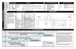
ELECTRICAL SEQUENCE
Refer to the wiring diagram.
Ice Vending:
Ice is dispensed as long as the ice vend lever or
push button is pushed, or until the hopper is empty
of ice.
• When the ice vend lever or push button is
pushed, the vend switch closes, and makes a
circuit to the coil of relay A.
• When relay A is energized, relay A’s contacts
6-9 and 7-4 close. Relay A’s contacts 7-1 open.
• When relay A’s contacts 6-9 close, they make a
circuit to the door solenoid, which opens the ice
door.
• When relay A’s contacts 7-4 close, they make a
circuit to the coil of relay B.
• When relay A’s contacts 7-1 open, the circuit to
the timer is opened.
• When relay B’s coil is energized, it closes a
circuit to the gearmotor, and the motor turns the
rotor.
Stand By:
• Relay A’s contacts 7-1 are closed and make a
circuit to the timer.
• The timer is energized when the unit is not
dispensing. The timer switch will close for a few
seconds every two hours.
• When the timer switch is closed, it makes a
circuit to relay B’s coil.
• When relay B is energized, it powers the
gearmotor, and the rotor is turned.
Soda Dispensing
Soda beverages are dispensed as long as the
valve levers or push buttons are held in, and there
is CO2 and syrup.
• The key switch is closed, the circuit to all of the
valves is enabled.
• When a valve lever or push button is pushed in,
the valve switch will close, making a circuit to
the coils of the valve which opens it.
June 1995
Page 21
RS160 and RS220
MOVING
If the dispenser is going
to be moved to another
building, shipped any distance, or if there is any
possibility that it may be exposed to freezing
temperatures, it must be thoroughly cleaned of all
liquids to prevent damage.
4. Remove connectors from syrup tanks.
5. Connect an empty syrup tank to one circuit.
6. Actuate valve on that circuit until only CO2 (gas)
flows from it.
7. Repeat steps 5-6 for all valves.
8. Remove all ice
1. Sanitize syrup system as instructed on page 15.
2. Shut off water supply.
9. Drain all water from bin and drain circuit.
10. Remove all field connections from cold plate.
3. Unplug carbonator.
June 1995
Page 22
RS160 and RS220
REMOVAL & REPLACEMENT
To Replace Gear Motor Assembly:
Electrical Shock Hazard.
Unplug unit before
servicing.
1. Disconnect electrical power.
2. Remove cover from hopper.
3. Unscrew sweep arm holding rotor to gearmotor
shaft.
To Replace Vend Switch:
1. Disconnect Electrical Power.
2. Lift up and pull out and remove upper front
panel.
Lever Type Actuation:
A. Twist ice chute 1/3 turn and pull down to
remove.
B. Remove screws holding valve mounting plate to
cabinet. Pull valve and plate assembly out and
away from cabinet. Switch is mounted to valve
plate.
Light Tube
Reverse steps to reassemble.
4. Remove rotor from gearmotor shaft.
Push Button Actuation:
5. Remove splash panel.
Locate vend switch behind push button assembly
of upper front panel.
6. Remove upper panel.
3. Remove wires from switch.
7. Twist ice chute 1/3 turn and pull down to remove.
8. Remove ice chute mounting plate.
4. Remove screw and nut retaining switch to
mounting plate, and remove switch from dispenser.
5. Reverse steps to reassemble.
9. Remove screws holding valve mounting plate to
cabinet. Pull valve assembly out and away from
cabinet.
10. Mark location of gearmotor bracket on
cross-brace.
11. Disconnect gearmotor electrical leads in
control box
12. Remove (4) screws holding gearmotor bracket
to cross brace.
13. Pull gearmotor & bracket from cabinet.
14. Remove bracket from gearmotor.
15. Reverse to reassemble. Gearmotor bracket
should be installed where it was, so that the rotor
should clear bin surface by 1/8" to 1/4". If needed,
the slots on the gearmotor bracket will allow the
position of the rotor to be adjusted.
June 1995
Page 23
RS160 and RS220
REMOVAL & REPLACEMENT
To Replace Solenoid:
5. Disconnect electrical leads from solenoid.
1. Disconnect electrical power.
6. Straighten cotter pin, and remove pin from
solenoid plunger.
Electrical Shock Hazard
Unplug unit before
servicing.
7. Remove rubber mounting screws holding
solenoid to cabinet, and remove solenoid from
cabinet.
8. Reverse to reassemble.
To Replace Light:
2. Lift up and pull out and remove upper front
panel. Remove fluorescent tube
1. Disconnect electrical power.
3. Remove 2 thumb screws holding lower brace
and remove.
3. Twist fluorescent tube out of sockets.
2. Pull out and remove upper front panel.
4. Reverse to reassemble.
4. Remove 3 thumb screws holding upper ice
chute cover, and remove cover. Remove the metal
solenoid cover.
June 1995
Page 24