1
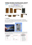
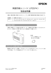
SERVICE INFORMATION
FUJIFILM MEDICAL SYSTEMS U.S.A., INC.
TECHNICAL ASSISTANCE CENTER
419 WEST AVENUE
STAMFORD, CT 06902
BULLETIN NO.
TELEPHONE 800 272-8465
RANK
EDMS NO.
14-029
CSS-0032016-A
EFFECTIVE DATE
July 10, 2014
Mandatory
CAPA SOURCE(S)
N/A
PRODUCT Applicable to all D-EVO panel
detectors
SUBJECT: D-EVO DETECTOR CALIBRATION FOR DR-ID 600, 700, AND 800 SYSTEMS
In this Service Bulletin, the necessary steps and procedures will be discussed for
calibrating all D-EVO detectors on DR-ID 600, DR-ID 700 (FDR Flex), and DR-ID 800
(FDR Go) systems. The procedures discussed will pertain to the DR-ID 600 service
manual (document #: 023-201-16E).
D-EVO Panel Calibration Table and Exposure Techniques
The calibration procedure is presented in section: Installation (IN) – Installation
Procedures (V3.X/V4.X) – 14. Calibration section in the DR-ID 600 Service Manual.
Follow the steps below to complete a successful D-EVO Panel calibration:
1. Install the Machine Shipment Data, which comes with every new panel. This data
should be saved on another storage media and the original disk kept in a safe
location. Refer to section Installation (IN) – Installation Procedures (V3.X/V4.X) – 12.
Installing the RU Software section 12.1.10 “Installing the Machine-Specific Data” in the
DR-ID 600 Service Manual.
2. Check the background calibration automatically executed upon startup of the
machine is completed before carrying out calibration as follows:
- If the FDX Console application is turned off, wait unit the panel stops flashing the
green led light before proceeding with the calibration.
Issued By: CSC, [email protected]
Page 1 of 7
Template: CSS-0000173-D
SERVICE INFORMATION
- If the FDX Console application is turned on, wait until “Calibrating” and “Urgent use
is possible” messages are clear under the “Reading Device” area in the FDX Console
before proceeding.
D-EVO
Model
Reference:
600SE-G35
601SE-G35i
602SE-G43i
613SE-C24i
611SE-C35i
612SE-C43i
Note: For DR-ID 800 (FDR Go) systems only:
Chart 1: D-EVO Technique Chart for all Calibrations (DR-ID 600 Service Manual 023-201-16E)
Issued By: CSC, [email protected]
Page 2 of 7
Template: CSS-0000173-D
SERVICE INFORMATION
3. Chart 1 displays the proper techniques for all four calibrations and panel types.
Use a dosimeter to determine the kV and mAs needed to make the required dose for
each of the three calibrations.
Note: Per ECN No. 2014-E-0123, for DR-ID 800 (FDR Go) systems the Lag
Calibration for all D-EVO panels has a different technique associated only with the kV,
as highlighted in red in the chart above.
4. D-EVO Panel Exposure Preparation:
- Clean the SE exposure plane with a dry cloth.
- Position the X-ray tube at an SID usually used at the installation site. For calibrations
completed outside the bucky and table top, place a lead apron under the panel for a
SID of 72 in.
- Adjust the irradiation field to cover the entire exposure plane.
- Start up the MUTL.
- Click [Calibration].
5. Refer to the Installation (IN) – Installation Procedures (V3.X/V4.X) – 14. Calibration
in the DR-ID 600 Service Manual for proper calibration procedure through the MUTL
of the RUPC Tool.
-For improve image quality and uniformity, it is recommended for the Gain calibration,
to rotate the panel 90 degrees every four exposures. Also, for the Defect calibration,
rotate the panel 90 degrees after every exposure.
Issued By: CSC, [email protected]
Page 3 of 7
Template: CSS-0000173-D
SERVICE INFORMATION
Procedure for Checking Proper Calibration
To check for proper D-EVO panel calibration, follow these steps:
1. After the calibration, back up the Correct Panel X Data for the registered panel from
the RUPC Tool under [BACKUP]. “X” refers to the register panel number under SE
Setting in MUTL.
2. In the Correct Panel X Data folder backup, open the DV.txt file in Notepad.
3. To confirm the number of lines in the DV.txt, follow the steps below:
-Count the number of lines in the file and match the panel size and number of lines
given below:
- 14x17 panel size: 19 lines or more
- 17x17 panel size: 23 lines or more
- 24x30 panel size: 13 lines or more
- If the lines counted are greater than or equal to the number given above, then the
calibration has been completed successfully. If less than, then the calibration fails.
Figure 1 gives an example of a calibration completed successfully for a 14x17 panel.
Figure 1: DV.txt file for a 14x17 D-EVO panel with 21 lines of calibration data.
Issued By: CSC, [email protected]
Page 4 of 7
Template: CSS-0000173-D
SERVICE INFORMATION
GLG (Drop Sensor) D-EVO Panel Calibration Procedure
The GLG calibration performs a zero point adjustment for the G sensor in the X, Y,
and Z directions. A GLG calibration is needed under the following conditions:
- for a new panel install
- if the GLG (drop sensor) log is giving incorrect data
- replacement of the GLG board or the GLS board
Refer to section Maintenance Utility (MU) – 1. PC-Tool –1.4 MUTL section 5.2.1 “SE1
Board State / GLG Calibration” in the DR-ID 600 Service Manual.
Follow the steps below to complete a GLG calibration:
1. Start the RUPC Tool on the FDX Console and click [MUTL].
2. Place the D-EVO Panel onto a stable surface with no vibrations (the orientation of
the panel does not matter).
3. Select [BOARD STATE CHECK]. Input the SE Number in the field and click [SET].
Figure 2: Input Panel Number window of MUTL
Issued By: CSC, [email protected]
Page 5 of 7
Template: CSS-0000173-D
SERVICE INFORMATION
4. Select [GLG CALIBRATION] as shown below.
Figure 3: GLG Calibration selection window
5. Click [GET X AXIAL OFFSET], [GET Y AXIAL OFFSET], [GET Z AXIAL OFFSET].
(The order of clicking does not matter.) There should be an “OK” message displayed
on the left of the screen for each option selected.
6. Click [SAVE OFFSET DATA]. There should be an “OK” message displayed on the
left of the screen as shown in Figure 4. You do not need to restart the MC or MP.
- The offset value is stored in the FRAM of the GLG board.
Issued By: CSC, [email protected]
Page 6 of 7
Template: CSS-0000173-D
SERVICE INFORMATION
Figure 4: Final display screen after the GLG Calibration is fully completed.
Issued By: CSC, [email protected]
Page 7 of 7
Template: CSS-0000173-D