1
September 5, 2011
★Reliable technology ensures maximum customer satisfaction.★
M-11011
Case
Correction of Service Manual Si-18
Model
Air Conditioning and Refrigeration Equipment
Please refer attached pages for correction of service manual Si-18.
Fundamentals of refrigeration
Si-18
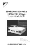
1.3.5 Sensible heat and latent heat
At Point B, the R410A refrigerant of 0.1MPa boils at a
temperature of -51.6°C.
Therefore, at Point D, if the R410A refrigerant having a
temperature of 35°C is in a state of saturated vapor at the
pressure of 2.12MPa, it becomes refrigerant saturated liquid of
35°C by removing the condensation latent heat from the said
saturated vapor.
By contrast, at Point C, that means it is required to reduce the
pressure down to 0.94MPa in order to boil the R410A refrigerant
at 5°C.
Fig. 1-34 shows the "temperatue-heat content diagram" for 1kg
of water heated from -50°C to 150°C vapor under the
atmospheric pressure.
(1) From A to B, 105.4kJ(25.2kcal) of heat were added to
increase ice temperature from-50°C to 0°C.
(2) From B to C, 333.2kJ(79.6kcal) were added to melt ice
without changing its temperature.
(3) From C to D, 418.6kJ(100kcal) were added to heat water to
boiling point. (from 0°C to 100°C)
(4) From D to E, 2256kJ(539kcal) were added to change water
to vapor without changing its temperature.
(5) From E to F, 92.5kJ(22.1kcal) were added to increase vapor
temperature from 100°C to 150°C.
In this example,
2 The heat which was required to increase the ice temperature
is called "sensible heat". (A to B)
2 The heat which was required to change the ice to water is
called "latent heat of melting". (B to C)
2 The heat which was required to increase the water
temperature is also called "sensible heat". (C to D)
2 The heat which was required to change the water to steam is
called "latent heat of vaporization". (D to E)
If the process is reversed,
2 The heat which must be rejected to change the steam to
water is called "latent heat of condensation". (E to D)
2 The heat which must be rejected to decrease the water
temperature is called "sensible heat". (D to C)
2 The heat which must be rejected to change the water to ice is
called "latent heat of solidification". (C to B)
2 The heat which must be rejected to decrease the ice
Fig.1-33
Saturated curve of R410A and Water
MPa
2.2
MPaG
2.1
D
2.12
2.0
1.9
1.8
1.7
1.6
1.5
Liquid
Gas
1.4
1.3
R410A
1.2
1.1
(Liquid)
Condensation
Vapor (Gas)
1.0
0.9
0.94
0.8
0.6
0.7
Liquid
Evaporation
temperature is called "sensible heat". (B to A)
0.5
Fig.1-34
0.4
0.3
Water
0.2
0.1
5
35
B
0
-40 -20
-51.6
0
20
40
60
A
0.1
0
-760mHg -0.1
80 100 120
Temperature (ºC)
mmHg
18
Fundamentals of refrigeration
Si-18
Fig.1-53
Evaporating
temperature
Temperature
Pressure
28
Mollier chart
Si-18
Chapter 2 Mollier chart
Fig.2-1
Pressure
The state of refrigerant in a refrigeration cycle varies with a wide
range of conditions while an air conditioner or a chiller is in
operation.
When the changes in state under these conditions are plotted on
a chart, each state and the numerical values of the state in every
part of the equipment can be estimated.
Furthermore, the capacity or the operating state can be
estimated using these values. This chart is called the P-h Chart.
The vertical axis of the P-h Chart specifies the pressure (P), and
the horizontal axis specifies the specific enthalpy (h). The P-h
Chart is therefore sometimes referred to as "Pressure-enthalpy
Chart". Furthermore, this Chart has received another name
derived from the name of the inventor of the Chart, that is,
"Mollier (or "Morieru" in Japanese) Chart".
The P-h Chart consists of 8 kinds of lines in all; saturated liquid
line, saturated vapor line, constant temperature lines, constant
specific volume lines, constant dryness lines and constant
specific entropy lines as well as constant pressure lines and
constant enthalpy lines. It looks like a map, which shows the
refrigerant properties diagrammatically. The methods of drawing
the lines vary to some extent with the types of refrigerants, while
the basic method of reading the lines does not vary. In this
textbook, the R22 refrigerant (fluorocarbon: HCFC22, most-often
used for air conditioning), is used as the teaching material.
Furthermore, SI unit (International System of Units) is used to
represent the unit.
2.0
2.0
1.0
1.0
0.6
0.6
0.4
0.4
0.2
0.2
0.1
0.1
Q. 1
Chiller is operating with the use of R22 refrigerant. The low
pressure gauge shows 0.5MPa G and the high pressure gauge
shows 1.7MPa G. Show each of these pressures on the P-h
Chart using horizontal lines.
2.1.2 Specific enthalpy: h [kJ/kg]
The specific enthalpy is graduated on the horizontal axis.
Therefore, constant specific enthalpy lines are shown with
vertical lines. This scale is proportionally graduated. Therefore,
the numerical values must be read as accurately as possible.
The specific enthalpy is the sum of internal energy and work
energy; which can be defined as the total amount of heat held by
the refrigerant in a given state.
On the P-h Chart, the specific enthalpy of 1 kg mass of saturated
liquid at 0°C is defined as 200 kJ/kg.
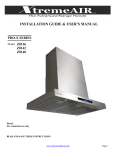
2.1 Composition of P-h Chart
2.1.1 Pressure: P [MPa abs]
In the P-h Chart, pressure is graduated on the vertical axis.
Therefore, horizontal lines represent constant pressure lines;
and all points on the same horizontal line show the same
pressure.
The scale is logarithmic but not required to be bound for use.
The pressure scale is expressed in the value of absolute
pressure.
Fig.2-2
200
300
400
500
Absolute pressure = Gauge pressure + Atmospheric pressure
[MPa abs] = [MPa G] + 0.1 [MPa abs]
0˚C
Note: Under normal conditions, the "abs" of "MPa abs" is often
omitted. In this textbook, however, the "abs" consciously remains
shown for ease of understanding.
Saturated liquid
line
P-h Chart (R407C)
200
300
400
500
Specific enthalpy
Note: The specific enthalpy is scientifically defined as:
h = ue + Pv
32
h: Specific enthalpy
ue: Internal energy
P: Absolute pressure
v: Specific volume
Si-18
Mollier chart
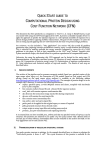
the superheated degree is 5°C, the suction gas temperature
rises by 5°C from the evaporating temperature of 6°C, thus
reaching a temperature of 11°C. The pressure is kept constant
up to this point, therefore the Point 1 of intersection of the
extension of the constant pressure line of 0.6MPa abs and the
11°C constant temperature line that tilts toward the right by 1°C
from the 10°C constant temperature line is taken as the suction
point of the compressor.
Fig.2-14
Pressure MPa abs
Evaporation
Com
pre
ssio
n
Condensation
Expansion
Pressure MPa abs
Fig.2-13
Specific enthalpy kJ/kg
2.2.2 How to draw actual operating state on P-h
Chart
In order to draw the refrigeration cycle on the P-h Chart, the
following four operating conditions are required. In other words, if
the four conditions are known, the refrigeration cycle can be
drawn on the P-h Chart.
Conditions:
1. Evaporating pressure or evaporating temperature
2. Suction gas temperature or superheated degree
3. Condensing pressure or condensing temperature
4. Liquid temperature at expansion valve inlet or sub-cooled
degree
Superheated degree = Suction gas temperature - Evaporating
temperature
Sub-cooled degree = Condensing temperature - Liquid
temperature at expansion valve inlet
10ºC
11ºC
1
0.6
0ºC
Specific enthalpy kJ/kg
Note: Strictly speaking, the pressure varies while showing a slight drop
in the evaporation process, while the pressure is assumed to be
constant on the P-h Chart.
2. Compression process
The compression process starts from the Point 1. While in this
process, a line is drawn according to the changes of the constant
specific entropy, that is, in parallel with the specific entropy line
up to the Point 2 of intersection with the line of condensing
pressure (high pressure) of 1.4MPa abs corresponding to 36°C
condensing temperature.
Whereas, this specific entropy line is slightly curved, and the
Point 1 does not always comes on the specific entropy line on
the Chart. Therefore, it is practical to find the Point 2 according
to a position on the condensing pressure line having the
numerical value of specific entropy equal to that at the Point 1
and draw the line of the compression process by connecting the
Points 1 and 2.
The Point 2 represents the discharge gas state from the
compressor.
Procedure
Draw the refrigeration cycle on the R22 P-h Chart based on the
following operating conditions.
Conditions:
Evaporating temperature = 6°C
Condensing temperature = 36°C
Superheated degree = 5°C
Liquid temperature at expansion valve inlet = 31°C
1. Evaporation process
Even though the refrigeration cycle can be started to draw from
anywhere on the P-h Chart, it is usually started from the
compressor suction point, that is, the completion point of the
evaporation process.
Since the evaporating temperature is 6°C, a horizontal line is
drawn from the 6°C graduations on the saturated liquid line and
the saturated vapor line. The starting point of the evaporation
process has not yet been known at this stage. Therefore, the
horizontal line may be tentatively drawn to the right from a point
with a dryness factor of about 0.4.
The evaporation process is represented with a horizontal line
due to changes under constant pressure. In this case, the
pressure is 0.6MPa abs, which is referred to as the evaporating
(or low) pressure.
Check the superheated degree given in the above conditions to
determine the point where the refrigerant is discharged from the
evaporator and sucked into the compressor. In this case, since
37
Mollier chart
Si-18
4. Expansion process
2
.76
kJ/
(kg
·K)
40ºC
30ºC
1.4
The expansion process starts from the Point 3. While in this
process, a line is drawn according to the changes of the constant
specific enthalpy, that is, in parallel with and perpendicular to the
specific enthalpy line up to the Point 4 of intersection with the
line of the evaporating pressure of 0.6MPa abs.
The distance between the Point 4 where the evaporation starts
and the Point 1 represents the evaporation process.
The expansion process is performed according to the constant
change of the specific enthalpy. Even though there are no
external heat exchanges, the temperature of the liquid
refrigerant falls from 31°C to 6°C. The reason is that when the
liquid refrigerant pressure is reduced due to the frictional
resistance while passing through the expansion valve or
capillary tube, part of the liquid instantaneously vaporizes to
decrease the liquid temperature.
S=
1
Pressure MPa abs
Fig.2-15
0.6
Specific enthalpy kJ/kg
Note: The compression process is drawn as theoretical adiabatic
compression. Therefore, it may be slightly different from that in actual
operation.
Fig.2-17
250
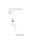
3. Condensation process
Pressure MPa abs
2
3
0.6
1
4
250
Specific enthalpy kJ/kg
Note: It is understood that, even though the refrigerant is in the lowtemperature low- pressure liquid state when it is discharged from the
expansion valve, actually moist vapor having a dryness factor of 0.16
enters the evaporator.
Fig.2-16
Exercise 2
Draw a refrigeration cycle on the P-h Chart under the abovementioned conditions. Then, read the following numerical values
of the four Points 1, 2, 3, and 4. (If the column which cannot be
read from the Chart, fill it with an oblique line.)
3
1.4
1.4
x=
x=
0. x= 0.1
2 0.
16
Pressure MPa abs
The condensation process starts from the Point 2. Heat
exchange in this process is performed mostly in the condenser,
but the condensation process itself starts at the discharge point
of the compressor.
At the Point 2, the condensing (high) pressure is 1.4MPa abs,
which is equal to the condensing temperature of 36°C. Since the
condensation process is a heat radiation process under constant
pressure, draw a line horizontally to the left from the Point 2.
While in the condensation process, the refrigerant changes from
superheated vapor to moist vapor, and further to sub-cooled
liquid, thus proceeding to the expansion process. In this case,
the temperature of liquid at the expansion valve inlet is 31°C.
Therefore, the Point 3 of intersection of the pressure line of
1.4MPa abs with the 31°C constant temperature line that tilts
toward the right by 1°C immediately before the 30°C constant
temperature line is taken as the point where the condensation
process is complete.
2
40ºC
31ºC
30ºC
1
Specific enthalpy kJ/kg
Note: The pressure also varies while showing a slight drop in the
condensation process, while the pressure is assumed to be constant
on the P-h Chart.
38
Mollier chart
Si-18
2.2 How to draw refrigeration cycle
Fig.2-11
Fig.2-9
High pressure
Superheated
vapor
3. Condensation (Change of phase in the condenser)
Moist
vapor
The condensation is a process in which the high-temperature
high-pressure discharge gas from the compressor is condensed
(liquefied) through cooling water or outdoor air in the condenser.
On the P-h Chart, this change of phase is represented by
drawing a line from right to left with a constant pressure line, that
is, a horizontal line.
Subcooled
liquid
Fig.2-12
Pressure MPa abs
The evaporation is a process in which the low-temperature lowpressure liquid refrigerant evaporates while removing heat from
the indoor air or moisture. On the P-h Chart, this change of
phase is represented by drawing a line from left to right with a
constant pressure line, that is, a horizontal line.
Pressure MPa abs
Fig.2-10
Condensation
n
1. Evaporation (Change of phase in the evaporator)
ssio
Expansion valve
Specific enthalpy kJ/kg
pre
Compressor
Condenser
Evaporator
Moist vapor
Superheated
vapor
Evaporation
Evaporation
Com
Low pressure
Com
p
Pressure MPa abs
Chiller and air conditioners consist of four major components
such as evaporator, compressor, condenser, and expansion
valve. The refrigerant flows through these components and the
process of evaporation → compression → condensation →
expansion repeats to carry out refrigeration. This process is
called the refrigeration cycle.
ress
ion
2.2.1 Vapor compression refrigeration cycle
Specific enthalpy kJ/kg
4. Expansion (Change of phase in the expansion
valve or capillary tube)
Evaporation
The expansion is a process in which the pressure of the
condensed liquid refrigerant is reduced through the expansion
valve (or capillary tube) to an evaporation pressure required. In
this process, since there is no heat transmission between the
refrigerant and the surroundings, the phase changes according
to the constant specific enthalpy.
In general, the liquid refrigerant at the inlet of the expansion
valve is sub-cooled by 5°C below the condensing temperature.
Therefore, on the P-h Chart, this change of phase is represented
by drawing a vertical line from top to bottom from the left side of
the saturated liquid line.
Specific enthalpy kJ/kg
2. Compression (Change of phase in the
compressor)
The compression is a process in which the compressor sucks in
gases generated through the evaporation process and
compresses the gases into high-temperature high-pressure
superheated vapor. This process is taken as the adiabatic
compression, that is, the constant specific entropy change.
In general, the suction gas into the compressor has a
superheated degree of 5°C. Therefore, on the P-h Chart, this
change of phase stage is represented by drawing an upwardslopping line from the right side of the saturated vapor line, along
the constant specific entropy line.
36
Electrical wiring
Si-18
(4) Thyristor [SCR] (SCR : Silicon Controlled Rectifier)
Thyristor
Thyristor is a power control element consisting of P and N
type semiconductors connected in 4 layers.
This is used in speed control of DC motor, light control
device of electric lamp and non-contact switch utilizing its
rectifying and switching functions.
Moreover, the thyristor can turn on and off the extremely
high voltage/current of several thousand volts and several
thousand ampere with one element which is so small that
it is placed on our palm.
Thyristor (SCR: Silicon Controlled Rectifier)
(5) Triac
Triac
Triac is a 3-polar dual direction thyristor which can flow
electric current in both directions (AC) and functions with
both positive and negative gate voltages. The functions are
the same as those obtained by combining thyristors in
parallel and in reverse direction.
Triac has a 5-layer structure of NPNPN, which is the same as SSS, and is used for AC non-contact switch, electric heater control,
light adjusting device, three-phase motor control and temperature control of copy machines (Xerox, PPC). In Daikin products, it is
used for phase control of indoor unit fan of room air conditioners and sky air systems.
*
Photo triac
Photo triac
Photo triac functions when light is emitted instead of
applying gate voltage, and is often used as light receiving
element of photo coupler. It is also often incorporated into
phase control circuit of fans by combining with light
emitting diode (LED).
(6) Dyac
Dyac
Dyac is often used as the trigger element in AC phase
control circuit such as muffling access ignition device of
water boilers, etc..
Another name of dyac --- Dual direction diode thyristor
Diac
124
Si-18
Electrical wiring
(7) Thermistor
Thermistor has a characteristics that the resistance lowers
as the temperature rises, which is opposite to that of
normal resistor. (NTC thermistor)
By utilizing this characteristics (resistance change),
thermistors are incorporated into the sensors of electronic
thermostats in room air conditioners, Sky-Air system and
boilers.
Thermistor
Code and characteristics
of thermistor
code
(8) Regulator
Regulator is an IC for power stabilization. The regulator
can control the output voltage to a constant level
regardless of the input voltage.
The accuracy of regulator is higher than that of zener
diode, and can take a heavy power source out.
Regulator
(9) Comparator
Comparator
Comparator compares two input voltages and outputs the
result as "H" or "L". The input terminal has positive side
and negative side, and if the voltage input to positive side
is higher than that input to negative side, the results is
output as "H", while "L" is output in the opposite case.
The figure below shows this function using a relay as an
example.
(10) Ope. amp
Ope.amp
Ope. amp is an integrated circuit called as calculation
amplifier. It is used for 1) calculation, 2) lmpedance
change, 3) measurement control and 4) oscillator, etc. by
connecting to an appropriate external circuit.
125
TYPE
Basic works
Si-18
6.10.1.6 Specifications of Service Checker TPYE III
Item
Specifications
External dimensions (excluding projecting sections) 180 (width) ✕ 150 (depth) ✕ 45 (height) mm
Weight
Approx. 700g
Power supply
9VDC, 300mA (Outside:+) (Use an AC adapter or battery of [TYPE3 Power Unit (220V)]).
Power consumption
Approx. 1.2W
Battery drive time
Approx. 8 hours after complete charging (when using a battery attached to [TYPE3 Power Unit
(220V)]).
Temperature and humidity conditions
-10 to 55°C (-10 to 35°C for AC adapters), 95% RH or less (no condensation)
RS232C interface
Asynchronous (19200bps), D-sub 25-pin female (straight connection to a personal computer)
Sensor input section
Temperature at 6 points(one point for discharge pipe), pressure at 2 points (high pressure and
low pressure) Two out of the 6 points can be switched to receive to voltage signals (0 to 1V or
0 to 5V).
TYPE
6.10.1.7 Standard configuration
Product name
Checker TYPE3
Parts number
999135T
Description
Service Checker TPYEIII
Cable for VRV-system air conditioner for building
Serial connector conversion cable
(Used when connecting M5, RAcable to the Service Checker)
RS-232C cable for personal computers
(D-sub 25-pin male/D-sub 9-pin female straight)
AC adapter
TYPE3 Power Unit (220V)*1
999142T
Input: 220VAC, 50Hz
Output: 9VDC, 500mA (Outside: +)
Temperature condition: -10 to 35°C
Battery: Ni-Cd battery
Charger: 220VAC input, 50/60Hz (Complete charging: approx. 16 hours)
TYPE3 Software (English)
999143T
Compatible with English-version Windows95/98/Me/NT4.0/2000/XP
TYPE3 Instruction Manual (English)
999144T
Instruction manual of TYPE3 software (English)
Purchase the above four items (total of 181,000yen).
6.10.1.8 Optional Items
Product name
M5, RA cable*1
Sensor Kit*1
Parts number
Description
999140T
Used when connecting to a Super Multi or room air conditioner via PCB
connection. No need to purchase this cable if customers have TYPE2
Expansion Kit (999112T).
999107T
High temperature thermistor (-30 to 150 ):
Low temperature thermistor (-30 to 70):
Air thermistor (-10 to 50):
High pressure sensor (0 to 30kg/cm2G):
Low pressure sensor (0 to 10kg/cm2G):
1pc.
3pcs.
3pcs.
1lot
1lot
6.10.1.9 Accessories
Product name
Parts number
TYPE3 cable for VRV-system air conditioner
for building*1
999141T
A set of cable of VRV-system air conditioner for building cable and serial
connector conversion. Attached to the Checker TYPE3
TYPE2 spare battery*1
999113T
Used to drive the Serivce Checker TPYE III.
Attached to the TYPE3 Power Unit (220V)
z
z
z
!
Description
Please follow Daikin's purchasing procedure.
Pentinum is a registered trademark of Intel Corporation.
Other product names mentioned above are trademarks or
registered trademarks of respective companies.
The above specifications may be modified for improvement
without any advance notice.
TYPE
Note :
Refer to the operation manual of Service Checker Type III for
more details.
204
Si-18
Installation
7.5 Cautions for installation
Examples of bad installation
If distributed air is short-circuitted, cooling or heating capacity
Before installing the unit actually at the predesigned position,
make sure to leave the service space indicated on the respective
installation and technical manuals around the unit, and at the
same time, examine various surrounding conditions.
will be greatly reduced.
Fig.7-21
7.5.1 Service space
In general, space for installation works is over 600mm and
space for service works is over 1200mm. With regard to the
details, see the technical manual.
In case two air cooled condensing units are installed in
parallel.
Minimum service space is shown below.
However, the minimum service space differs with models, so
follow the respective installation or technical manual as for
the details.
7.6 Making a pipe hole
Fig.7-20
Make a hole in the wall. In case of room air conditioners, suitable
hole diameter is 70~80mm.
The location of a hole should be lower than the drain outlet so
that drain water can be smoothly extracted outsides. In addition
the hole should be inclined downwards to the outdoor as shown
in the figure below.
Fig.7-22
7.5.2 Installation of units
Consider air distribution of a room based on structure of a
room and arrangement of occupants and furniture.
Install the unit in such a place where wall or obstacles do
not interrupt the air ways in and out of the unit. (If the air way
is disturbed, predesigned cooling efficiency is not
obtainable, and furthermore dew forms on the casing, which
may be resulted in water leakage.)
Avoid installing the unit in such a place which is near the
door or kitchen so as not to draw unnecessary volume of air
or stale air.
In case the unit is mounted in a wall, carefully install it not to
transmit operation vibration to the wall. Leave a sufficient
space for providing after-sales service.
Downward
217
Psychrometric chart
Si-18
Chapter 11Psychrometric chart
11.1 Air
Namely, the following figure represents the weight, pressure,
and volume of the moist air by the expressions.
Atmospheric air is referred to as "air", which means the moist air
in terms of air conditioning.
Fig.11-1
Dry air
Water vapor (Moisture)
Moist air
11.1.1 Properties of moist air
Moist air is a mixture of dry air and 1 to 3% mass of water vapor.
1. Properties of dry air
The composition of dry air in the standard state
(temperature: 0°C, pressure: 760mmHg {101.325kPa},
acceleration of gravity g = 9.80655 m/S2) is as follows.
Weight 1 [kg]
+ X [kg]
= 1+X [kg]
Volume V
+ V
= V
Pressure Pa [kg/cm2] + Pw [kg/cm2] = P [kg/cm2]
=1.03323kg/cm2
= P {kPa} =101.325kpa
Pa{kPa}
+ Pa{kPa}
(Partial pressure)
(Partial pressure)
(Total pressure)
Table 11-1
Composition Nitrogen
(N2)
Oxygen
(O2)
dioxide
Argon (Ar) Carbon
(CO2)
Volumetric
(%)
78.09
20.95
0.93
0.03
Gravimetric
(%)
75.53
23.14
1.28
0.05
11.1.3 How to represent water vapor (Humidity)
in moist air
There are different kinds of method available to represent the
humidity.
*1 Constant pressure specific heat of dry air Cpa
=0.240 [kcal/kg • deg] =1.005 {kJ/kg • K}
*2 Enthalpy of dry air ha
=0.240t [kcal/kg]
=1.005t {kJ/kg}
This means the enthalpy of dry air at arbitrary
temperature and pressure based on the condition that
the enthalpy of dry air is 0 at a temperature of 0°C and
standard atmospheric pressure.
1. Relative humidity [φ=%]
(
)
(a)
2. Properties of water vapor
Constant pressure specific heat of water vapor Cpw
=0.441 [kcal/kg • deg]
=1.85 {kJ/kg • K}
Evaporation latent heat of water vapor r
=597.3 [kcal/kg]
=2501 {kJ/kg}
Enthalpy of water vapor hw
=r+Cpwt=597.3+0.441t [kcal/kg] =2501+1.85t {kJ/kg}
Water vapor enthalpy hw at arbitrary pressure and
temperature is shown as a function of temperature t°C
alone, under the condition that the enthalpy of
saturated water at 0°C is 0, and the pressure and
temperature are not so high.
(
(b)
8
)
8
11.1.2 Moist air
The relative humidity is the ratio of the moist-air specific
weight to the saturated-air specific weight, or the ratio of the
water vapor partial pressure Hw [mmHg] {kpa} in given
moist air to the moisture partial pressure Hs [mmHg] {kPa}
in saturated moist air at the same temperature.
y = Specific weight [kg/m3] (Specific weight = 1/Specific
volume)
This is the weight of water vapor [kg] contained in 1-m3
moist air.
Saturated moist air
When the temperature t of moist air is equal to the
temperature t of saturated water vapor corresponding to the
partial pressure Hw of the water vapor, the air is called
"saturated moist air" or "saturated air" in short.
When pressure and temperature are determined, the limit of
water vapor containable in the said air is also determined.
This air containing water vapor up to the limit is called
saturated air.
2. Absolute humidity [X = kg/kg]
It is convenient to assume that the moist air is an ideal gas that
is mixture of dry air of 1kg in a certain composition and water
vapor of X [kg] variable with state.
Thus, concerning moist air, a variety of numerical values are not
handled for the unit weight of mixed gas of dry air and water
vapor, while the mixed gas of 1 kg of dry air and X [kg] of water
vapor, that is, (1+ X) kg of air is used as one unit weight.
X in Fig. 1.1 represents the absolute humidity itself. The
weight ratio of water vapor contained in the moist air
becomes X/1 [kg/kg] to 1-[kg] dry air contained in the moist
air. In other words, this is the ratio of the moisture weight to
the dry air weight, both of which are contained in the moist
air.
286
Si-18
Psychrometric chart
[Example of calculation]
From Equation (5.8),
2. When a model is not assumed
Generally speaking, in this case, set up conditions and
proceed with planning with a concept to newly produce an
air conditioner conforming to the apparatus. Namely,
Referring to information in Section 5-1 (3) "(b) When the
airflow rate has not been determined", tentatively determine
the airflow rate, then, take this airflow rate as a reference to
determine the model of air conditioner.
qp = G (h3 – h5) [kcal/h]
qp =
1
3000
5G (h
3–
h5) {kw}
h6
h5 = h3 –
qP
qP
= h5 –
G
1.2 Q
h5 = h3 –
3600 qP
3000 qP
= h3 –
{kJ/kg}
G
Q
5
5
5
Example
Substituting h3 and h5 into Equation (5.13), the Equation
will be
h5 = h5 –
(h3 – h5)
CF
When finding a cooling load required to maintain the
conditions of a given room at 26°CDB and 50%RH, qs =
8,000 kcal/h {9.30kw} and qL = 2,000 kcal/h {2.32kw}. Find
the SHF of this room. When the bypass factor BF of the
evaporator is 0.11, what is the dry-bulb temperature
required to discharge air at a point on the SHF line?
5 BF
Find BF according to the technical data to calculate the
h6.
Draw a straight line between Point and Point obtained from h5 on the psychrometric chart and find t5
through the intersection of the straight line and h5.
(c) Availability of model assumed
If the air conditioner outlet temperature t5 found in Section
(b-3) is lower than the design discharge temperature t4 and
located below the apparatus SHF line found by Equation
(5.1), the design air conditions are satisfied, making it
possible to proceed with calculations according to the model
assumed. Fig. 11-28 shows that on the psychrometric chart.
[Solution]
From Equation (5.1),
8,000
qs
SHF =
=
= 0.8
8,000 + 2,000
qs + qL
Use the psychrometric chart of discharge temperature to
find the SHF.
9.32
qs
SHF =
=
= 0.8
9.30 + 2.32
qs + qL
Fig.11-29
Fig.11-28
3
5
6
5
4
Discharge temperature: 14.2˚CDB
3
It is good if the air conditioner outlet temperature t5 falls in
the shaded area in the above figure. If there is too large
difference between the air conditioner outlet temperature t5
and the design discharge temperature t4, it is required to use
a model of smaller capacity and reexamine the planning
since the capacity of the assumed model is too large.
297
Psychrometric chart
Si-18
11.6.2 Selection of model with priority given to
apparatus and airflow rate
Fig.11-39
In cooling operation
1. Find the sensible heat factor.
From Equation (5.1),
qS
SHF=
qS+qL
2. Plot the proven conditions on the psychrometric
chart.
Indoor condition ..................................Point Outdoor-air condition
(When outdoor air is taken in).............Point SHF line...............................................SHF line found in .
X4: Absolute humidity at outlet point of humidifier
································· (kg/kg)
X5: Absolute humidity at inlet point or ' of heater
································· (kg/kg)
When the humidifying weight is determined, specify the
type from the optional accessories list in the Technical
Data.
Fig.11-41
When selecting with evaporative-plate-type humidifier,
Type: KEM104D15,
Humidifying capacity: 5.2 (kg/h), and
Power consumption: 4 (kW)
(h)Summary in heating operation
The cycle is shown on the psychrometric chart.
Fig.11-40
3. Find the airflow rate of apparatus.
Indoor point
Outdoor-air point
Mixing point = Heater suction point
Design discharge point = Outlet point of humidifier
Heater outlet point = Inlet of evaporative-plate-type
humidifier
' Heater outlet point = Inlet of water-spray-type
humidifier
{ Heater capacity = h5' or h5 - h3
h5': In the case of water-spray-type humidifier
h5: In the case of evaporative-plate-type humidifier
{ Indoor load: h4 - h1
{ Outdoor-air load: h1 - h3
{ Humidifying load: h4 - h5
{ Humidifying capacity: X4 - X5
(
kcal/h
3600 × qS kw
(qS : kcal,qS : kw)
1 (t1-t4)
1
1.005 ×
0.24 ×
× (t1-t4)
V4
V4
V4: Assuming the discharge point of apparatus,
calculate the specific volume of air. [m3/kg]
t4 : Assume the discharge point of apparatus. [°C]
How to assume t4
In the case of ordinary cooling operation, assume that the
difference (t1- t4) in temperature between suction and
discharge is 8 to 12 deg. and the relative humidity at the
discharge point falls in the range of 80 to 90%.
Q=
qS
=
4. Find the conditions of air at the inlet of
evaporator.
(a) When outdoor air is taken in the air conditioner
Find the mixing point , which is present on the straight line
connecting the outdoor-air point and the indoor point .
The point is defined as the suction point.
(From Equation (2.1))
t3 K • t2 + (1 - K) • t1 ............... [°C]
h3 K • h2 + (1 - K) • h1 ............ [kcal/kg]{kJ/kg}
)
304
Si-18
Psychrometric chart
Answers to Exercise 8
Find the mixed air
Answers to Exercise 9
.
Find the sensible heat factor SHF.
qS
From Equation (4.1): SHF=
qS+qL
8500
=
8500+7000
=0.548
From Equation (2.1), t3=K • t2 + (1-K)t1
t3=0.1×0+(1-0.1)×20
=18 [˚C]
h3=K • h2 + (1-K)h1
=0.1×1.1+(1-0.1)×9.4
=0.11+8.46
=8.57 [kcal/kg]
Write the SHF on the psychrometric chart and find the
conditions of suction air of air conditioner.
Enthalpy h1 of inlet air =12.65 [kcal/kg]
According to the above calculation, the mixed air reaches 18˚CDB and 54.5%RH.
Find the state
Fig.11-55
at the outlet of heating coil.
Substituting numerical value through Equation (4.10):
qH=Q× 1 (h3–h1)
V3
1
2800=6000×
× (h4-8.57)
V
2800
Assume that
h4=8.57+
1
V=0.882.
6000×
V(0.882)
=8.57+4.12
12.7 [kcal/kg] Thus, make sure through
the psychrometric chart.
Find the state
of air after humidification
Substituting numerical value through Equation (4.11):
LW=Q × 1 (X5 – X3)
V3
1
× (X5 - 0.0069)
10=6000 ×
V
10
Assume that
X5=0.0069+
V=0.875.
6000× 1
V
X5 8.57+4.12
=0.0084
Write the numerical values found in the above , , and on the psychrometric chart.
Fig.11-54
Find the discharge point of air conditioner.
qp
1.2×Q
2000
h2=12.65 1.2×3000
=12.65 - 5.56
=7.09 [kcal/kg]
From Equation (5.11): h5 h3 -
Write the enthalpy h5 at the outlet of air conditioner on the
psychrometric chart.
(h3 - h5)×BF
From Equation (5.13): h6=h5 CF
(12.65-5.56)×0.1
h6=7.09 (1-0.1)
0.0069+0.0015
=7.09-0.79
=6.3 [kcal/kg]
In order to provide the discharge point of air conditioner on
the SHF line.
Fig.11-56
Install a re-heater and determine the re-heater capacity.
309
Si-18
Simple cooling / heating load calculation
12.3 Design Conditions
Table 12-1 Composition of heat load
Heat
External load
Internal load
Indoor load
Heat source
Sensible heat Latent heat
Heat gain
(Cooling load)
Heat loss
(Heating load)
1. Roof·wall·partition·floor·ceiling
«Solar radiation, night radiation, temp. difference»
{
2. Window glass
«Solar radiation, night radiation, temp. difference»
{
3. Infiltration
«Temperature and humidity of infiltrated air»
{
4. Illuminant
«Generated heat»
{
5. Human body·equipment
«Generated heat»
{
{
Outdoor 6. Intake fresh air
air
«Temperature and humidity in outdoor air»
Table 12-2 Cooling load conditions
Dry bulb temp. (DB)
Wet bulb temp. (WB)
Relative humidity (RH)
Outdoor conditions
33°C
27°C
63°C
Indoor conditions
26°C
19.5°C
55°C
%
Note:
Since these conditions about indoor and outdoor are included in the coefficient "B" in the Cooling/Heating load list, the figuring out of
temperature difference is not required.
Table 12-3 Heating load conditions
Figure out the temperature difference from the following table.
Outdoor
temperature
°C
Brussels
Belgium
Shanghai
China
Hong Kong
China
Tokyo
Japan
Riyadh
Saudi Arabia
Buenos
Aires
Argentina
Paris
France
Sydney
Australia
-7
-3
10
-2
4
1
-4
5
Note:
1) These data are drawn out from ASHRAE HANDBOOK
2) When night heating is regarded as importance, reduce further 2 degrees from the above temp.
Table 12-4
Indoor temperature °C
State of action
Examples
22
Seated at rest or very light work
Office, theater, residence, restaurant, etc.
20
Little active
Factory (light work), school, store, etc.
18
Very active
Factory (Heavy work), dance hall, etc.
313
Si-18
R407C and R410A refrigerants
13.3 Refrigerant piping
13.3.1 Three basic rules of refrigerant piping
(2)Cleaning (free of contamination)
There shall be no dust in the pipe.
(3)Tightening (air-tightness)
There shall be no refrigerant leak.
Item
(1)Drying (no moisture)
There shall be no moisture in the
pipe.
Cause
(Z0134)
(Z0135)
(Z0136)
• Water entering from outside, such • Oxidized film generated during
• Insufficient brazing
as rain.
brazing.
• Inadequate flaring or insufficient
• Moisture due to dew condensation • Entering of foreign items such as
tightening torque.
occurring inside the pipe.
dust, particles and oil from outside. • Inadequate tightening of flange
connection.
• Clogging of expansion valve,
capillary tube, etc.
• Insufficient cooling or heating.
• Degradation of refrigerant oil.
• Malfunction of compressor.
• Clogging of expansion valve,
capillary tube, etc.
• Insufficient cooling or heating.
• Degradation of refrigerant oil.
• Malfunction of compressor.
• Gas shortage
• Insufficient cooling or heating.
• Temperature increasing of
discharge gas.
• Degradation of refrigerant oil.
• Malfunction of compressor.
Problem
<For reference>
Preventive measure
Compressor is corroded due to moisture.
Pipe preparation
Capillary is clogged with dust.
• Same as the items on the left.
• Do not use tools or devices
previously used with a different
type of refrigerant.
Flushing
• Follow the basic brazing
procedure.
• Follow the basic flaring procedure.
• Follow the basic flange connection
procedure.
• Conduct an air-tightness test (gas
leak check).
Vacuum drying
Remarks
(Z0137)
Pipe preparation
Flushing
Vacuum drying
---See page 13.
---See page 14.
---See page 22.
Basic brazing procedure
Basic flaring procedure
Air-tightness testing procedure
Gas leak check
---See page 15.
---See page 16.
---See page 19.
---See page 20.
--See page335
--See page336
--See page339
--See page340
--See page333
--See page334
--See page342
331
Si-18
Appendix
Merits and demerits of cleaning using chemical
z
z
z
z
z
z
Provided,
TC : Condensation temperature
TW : Cooling water temp. at condenser outlet.
t1 :Temp. difference when cooling pipe is clean.
t2 :Temp. difference when scale adheres.
There is selectiveness of scales, but almost all scales can
be removed, if the chemical is selected precisely. On the
other hand, if the mistake is made in the selection, the scale
cannot be removed, and more, in some cases, abnormal
corrosion is brought about.
In some cases, neutralization-treatment of drain is required,
after cleaning.
Even the cleaning of large-capacity is possible in a short
time.
Even the complicated water circuit can be cleaned.
Take care of metal corrosion by the cleaning chemicals.
Generally, this way is too expensive.
Do not be confused by the sudden stop of the operating cooling
(refrigerating) equipment, even though the high pressure switch
does not get to the function.
For this, it is necessary to examine the increasing rate of
"t2 — t1" and clean the scale in advance. Generally when
"t2 — t1" becomes over 3 to 5°C, cleaning is necessary.
4. Judgement after cleaning
Merits and demerits of cleaning using brush
z
z
z
z
z
z
The simplest and the most certain way is to confirm visually the
state of coming off the scale.
But, in some cases the visual confirmation is impossible
because the recent heat exchanger in a cooling (refrigerating)
equipment has hermetic or other complicated structure. For this,
it is important to compare the before and after cleaning, using
the ways mentioned above in the clause 3. when you neglect this
(confirmation of cleaning effect), even though the high pressure
is cut by other reasons than scale, sometimes it may be judged
that the cleaning made a mistake. More, the way of judgement of
the state of scale adhesion only by high pressure is not proper,
because the state changes depending on the temperature or the
volume of cooling water.
There is selectiveness of scales comparatively a little. And
very hard scales cannot be removed.
This is almost physical work, so personnel expenses are too
high.
In case of complicated or closed-type water circuit, a brush
cannot be inserted, that is the cleaning is impossible.
As the chemicals is not used, there is no fear of the drain
pollution.
Generally, this way can be cheap.
Effect of cleaning can be confirmed visually in the working.
3. Is cleaning necessary or unnecessary?
There are various ways to judge of the scale coating, but it is
general and certain way to judge be the degree of fall of the heat
exchange efficiency.
That is, when full load operating of the cooling (refrigerating)
system, 'the outlet temperature of the cooling water flowing in
the condenser' is compared with 'the condensation temperature
of the refrigerant'. And then this difference is compared with the
value at the clean time of the cooling pipe.
Finally, it is judged by how much the former has increased.
5. How to select chemicals for cleaning
An important factor in the chemical cleaning is to select the
proper chemicals depending on the type of scales. As a matter
of fact, analysis of composite scales should be consulted our
Daikin S.S. or the specialist of water treatment.
of
Condensation temp. Of refrigerant: This is found by conversion
to the saturation temperature of the refrigerant from the
indicating pressure of the high-side pressure gauge.
The strong point of this way is that the both temperature
differences are almost constant, even though the volume of
cooling water changes more or less. So, there are few cases of
misjudgement.
373