1
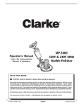
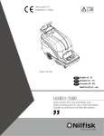
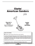
E
Division of
ULTRA SPEED
BURNISHER
1700
Operator's
Manual
READ THIS BOOK
This book has important information for the use and safe operation of this machine. Failure to read
this book prior to operating or attempting any service or maintenance procedure to your Clarke
machine could result in injury to you or to other personnel; damage to the machine or to other property
could occur as well. You must have training in the operation of this machine before using it. If your
operator(s) cannot read English, have this manual explained fully before attempting to operate this
machine.
All directions given in this book are as seen from the operator’s position at the rear of the machine.
For new books write to: Clarke® , 2100 Highway 265, Springdale, Arkansas 72764.
Form No. 70127C
10/02
Clarke®
Printed in the U.S.A.
Table of Contents
Operator Safety Information ..................................................... 3
Features and Specifications.................................................... 4
Pad Selection Chart ................................................................ 4
120 Volt Instructions for Electrical Connection ......................... 5
About the Machine .................................................................. 6
How to Prepare Machine for Operation ................................... 6
How to Operate the Machine ................................................... 7
Care and Maintenance ............................................................ 8
How to Correct Problems in the Machine ................................. 9
Section II - Parts and Service Manual
Maintenance ........................................................................... 12
Assembly Drawing .................................................................. 14
Assembly Parts List ........................................................... 15
Electrical Schematic ............................................................... 16
Motor Drawing and Parts List .................................................. 17
Page - 2 -
Clarke® Operator's Manual - Ultra Speed Burnisher 1700
OPERATOR SAFETY INSTRUCTIONS
WARNING
AVERTISSEMENT
ADVERTENCIA
DANGER means:
Severe bodily injury or death can occur to you or other personnel if the DANGER statements found on this machine or in this Owner's Manual are ignored
or are not adhered to. Read and observe all DANGER statements found in this
Owner's Manual and on your machine.
WARNING means:
Injury can occur to you or to other personnel if the WARNING statements
found on your machine or in this Owner's Manual are ignored or are not
adhered to. Read and observe all WARNING statements found in this Owner's
Manual and on your machine.
CAUTION means:
Damage can occur to the machine or to other property if the CAUTION statements found on your machine or in this Owner's Manual are ignored or are not
adhered to. Read and observe all CAUTION statements found in this Owner's
Manual and on your machine.
DANGER:
Failure to read the Owner's Manual prior to operating or attempting any service or maintenance
procedure to your machine could result in injury to you or to other personnel; damage to the
machine or to other property could occur as well. You must have training in the operation of this
machine before using it. If you or your operator(s) cannot read English, have this manual
explained fully before attempting to operate this machine.
DANGER:
Machines can cause an explosion when operated near flammable materials and vapors. Do not
use this machine with or near fuels, grain dust, solvents , thinners, or other flammable materials.
Precautions should be taken during the use of this machine to prevent formation of a combustible mixture of flyings and air. Use this machine only in a well ventilated area.
DANGER:
Operating a machine that is not completely or fully assembled could result in injury or property
damage. Do not operate this machine until it is completely assembled. Inspect the machine
carefully before operation.
DANGER:
Electrocution could occur if maintenance and repairs are performed on a unit that is not disconnected from the power source. Disconnect the power supply before attempting any maintenance
or service. Always remove the electrical plug from the electrical outlet before changing the brush,
pad or other attachment and before leaving the machine.
DANGER:
Using a machine with a damaged power cord could result in an electrocution. Do not use the
machine if the power cord is damaged. Do not use the electrical cord to move the machine.
WARNING: Maintenance and repairs performed by unauthorized personnel could result in damage or injury.
Maintenance and repairs must be performed by authorized personnel only. Keep all fasteners
tight. Keep adjustments according to specifications.
WARNING: Electrical components of this machine can "short-out" if exposed to water or moisture. Keep the
electrical components of the machine dry. Wipe the machine down after each use. For storage,
keep the machine in a dry building.
WARNING: Always use a three-wire electrical system connected to the electrical ground. For maximum
protection against electric shock, use a circuit that is protected by a ground fault interrupter.
Consult your electrical contractor.
WARNING: To prevent damage to the power cord, do not let the pad, pad driver or wheels touch the power
cord when the machine is running. Always lift the cord over the machine. Do not pull the power
cord to move the machine.
WARNING: Operating a machine without observing all labels and instructional information could result in
injury or damage. Read all machine labels before attempting to operate. Make sure all of the
labels and instructional information are attached or fastened to the machine. Get replacement
labels and decals from your authorized distributor.
WARNING: Use of this machine as a step or furniture could result in injury or damage. Do not use this
machine as a step or furniture. Do not ride on this machine.
Clarke® Operator's Manual - Ultra Speed Burnisher 1700
Page -3 -
OPERATOR SAFETY INSTRUCTIONS (cont.)
WARNING: To avoid injury keep hands, feet and loose clothing away from all moving parts of this machine.
CAUTION:
The machine is heavy. Get assistance before attempting to transport or move it.
CAUTION:
To prevent serious damage to the floor surface, when using burnisher, make sure the machine
is always moving forward or backward when the pad is in contact with the floor.
CAUTION:
To prevent overloading motor, do not use burnisher for wet scrubbing. There is no skirt on
burnisher to contain water. Water could splatter.
FEATURES AND SPECIFICATIONS
Electric burnishers are floor polishing machines. They are operated by moving them forward and backward
across the floor. Note: Do not use the machine for wet scrubbing.
CAUTION:
To prevent serious damage to the floor surface, make sure the machine is always moving forward
or backward when the pad is in contact with the floor.
Specifications
Model
01193B
Voltage (V)
Frequency (Hz)
120
50/60
Current (A)
Operators Handle
Pad Driver
12.5
plastic
20"
Burnishing Swath
Pad Speed (rpm)
20"
1700
Motor Horsepower
Power Cable Length (ft)
1.5
50
Weight (lbs.)
82
19" (48cm) 3M Burnishing Pad Selection Chart
Part No.
Description
Application
Use
RPM
Color
Finish
976289
Top Line
Burnish
Dry
1500-3000
Peach
Hard finish/high traffic
Soft finish/low traffic
976326
Natural Blend
Burnish
Dry
1500-3000
Off White
Hard finish/high traffic
Soft finish/low traffic
High traffic/low
Maintenance
976235
UHS Tan
Buffer
Burnish
Dry
1500-3000
Tan
Hard finish/high traffic
Wet-look hard finish
976236
UHS Aqua
Buffer
Burnish
Dry
1500-3000
Aqua
Soft finish/low traffic
Wet-look soft finish
Page - 4 -
Clarke® Operator's Manual - Ultra Speed Burnisher 1700
120 VOLT MACHINES
Instructions for connection to the power
supply and the electrical ground.
This product must be grounded. If it should
malfunction or breakdown, grounding provides a path
of least resistance for electric current to reduce the
risk of electrical shock. This product is equipped
with a cord having an equipment-grounding conductor
and grounding plug. The plug must be inserted into
an appropriate oulet that is properly installed and
grounded in accordance with all local codes and
ordinances.
WARNING: Improper connection of the
equipment-grounding conductor can
result in a risk of electric shock. Check
with a qualified electrician or service
person if you are in doubt as to whether
the outlet is properly grounded. Do not
modify the plug provided with the
product. If it will not fit the outlet, have a
proper outlet installed by a qualified
electrician.
GROUNDED
OUTLET
GROUNDED
OUTLET BOX
GROUNDING
PIN
Figure 1
This product is for use on a nominal 120 volt circuit
and has a grounding attachment plug that looks like
the plug illustrated in Figure 1. Make sure that the
product is connected to an outlet having the same
configuration as the plug. No adaptor should be
used with this product.
WARNING: To prevent possible electric
shock, protect the machine from rain.
Keep the machine in a dry building.
WARNING: To prevent possible electric
shock, always use a 3-wire electrical
system connected to the electrical
ground. For maximum protection
against electrical shock, use a circuit
that is protected by a ground fault circuit
interrupter. Consult your electrical
contractor.
WARNING: Do not cut, remove or break
the ground pin. If the outlet does not fit
the plug, consult your electrical contrac
tor.
WARNING: Have worn, cut or damaged
cords replaced by an authorized service
person.
EXTENSION CORDS
Use only an approved extension cord with three
conductors, a plug with three terminals, and a
connector body with three holes. The machine has a
power cord with wire size 14 AWG.
WARNING: If you use an extension
cord, use an extension cord with
minimum wire size 12 AWG. Do not use
an extension cord longer than 50 feet.
Do not join two extension cords.
Clarke® Operator's Manual - Ultra Speed Burnisher 1700
Page -5 -
ABOUT THE MACHINE
How To Assemble
This machine is shipped with the handle assembly
separate from the base. Assemble as follows:
1. Loosen but do not remove the two square head knobs
on the rear of the machine.
2. Insert the handle tube between the frame and handle
clamp until it bottoms.
3. Tighten the two square head knobs to secure the
handle tube.
4. Connect cord set to the motor pigtail.
Install a pad and the machine is ready to operate.
Figure 2
HOW TO PREPARE THE MACHINE
FOR OPERATION
How To Install the Pads
WARNING: Always remove the electrical
plug from the electrical outlet
before installing or changing the
pad.
The pad driver assembly is on the bottom underside of
the machine. The pad holder holds the pad in position.
The machine has a screw-on pad holder. To install the
pad, follow this procedure:
1. With the handle locked in the operating position, tilt
burnisher back on the handle until the underside of the
burnisher is fully exposed. (See figure 2).
2. Remove the retainer from the pad holder by unscrewing
(turn counterclockwise).
3. Remove the center scored circle from a pad.
4. Place pad on pad driver.
5. Be sure pad is properly centered on the driver.
6. Reinstall the retainer on the pad holder until pad is
tightly secured (turn clockwise).
NEVER OPERATE BURNISHER WITHOUT A PAD.
Page - 6 -
Clarke® Operator's Manual - Ultra Speed Burnisher 1700
HOW TO OPERATE THE MACHINE
WARNING:
Machines can ignite flammable materials and vapors.
Do not use with or near flammables, such as: gasoline,
grain dust, solvents and
thinners.
CAUTION:
Allowing the machine to run
without moving forward or
backward can cause serious
damage to the floor surface.
Make sure the machine is always moving when the pad is
rotating.
NOTE: You must have training in the operation of
this machine before you use it.
How To Start/Stop The Machine
1
2
2
Figure 3
The normal position of this burnisher, with the pad stationary, is tilted back with the pad off the floor.
1. Remove cable completely from cable hook.
2. With the handle in operating position and the power
cable plugged into the proper outlet, depress the
interlock button (1) and squeeze the levers beneath
the handle grips (2). (See figure 3).
3.
As the motor reaches full speed (1-2 seconds), bring
the pad into contact with the floor.
NOTE: Make sure you hold the handle with both
hands.
How To Operate the Machine
For best results, use a clean pad and change frequently
as pad loads up. A motor overload could result from a
dirty, loaded pad. If the built-in circuit breaker trips, turn
off the machine, wait five (5) seconds, then depress the
reset button on the circuit breaker. Change the pad.
The Circuit Breaker
A circuit breaker is used to protect the motor. If the motor
draws high current, the circuit breaker will stop the motor.
The circuit breaker reset button is on the rear of the motor
cover. Push the reset button to reset the circuit breaker.
If the motor continues to stop, consult an authorized
service person.
Clarke® Operator's Manual - Ultra Speed Burnisher 1700
Page -7 -
CARE AND MAINTENANCE
This burnisher will give you many years of trouble-free
service provided it is given proper care. Throwing,
dropping, bumping across the thresholds and other
misuse may result in a damaged unit and invalidate the
warranty. When storing your burnisher, always remove
the pad.
Pads can be cleaned by washing in warm water and a mild
detergent, rinsing, and hanging up to dry.
The pad driver spindle bearings should be re-lubricated
once a year. Do not over lubricate. Allow grease to enter
bearings slowly.
NOTE: Do not store the machine resting on the
pad driver, the pad driver will warp and cause
vibration.
Inspections and Repairs
Take the machine to the nearest Clarke authorized repair
location once a year for the maintenance inspections.
To make any repairs, take the machine to the nearest
Clarke authorized repair location.
WARNING:
Page - 8 -
Maintenance and repairs
must be done by authorized
personnel only
Clarke® Operator's Manual - Ultra Speed Burnisher 1700
HOW TO CORRECT PROBLEMS IN THE MACHINE
Cause
The machine will not run.
The machine may not have
any power.
Action
Make sure the machine is connected to
the correct voltage and frequency and
that all connections are tight or,
Make sure the machine is plugged in.
The power cord may be
damaged.
Contact an authorized service person
The pad is worn or dirty.
Clean the pad. If the pad is worn, replace it.
The main switch is defective.
Contact an authorized service person.
The circuit breaker is defective.
Contact an authorized service person.
The motor is defective.
Return to service center.
The bearings are dry.
Grease the bearings or return to service
center.
The belt is slipping.
Re-tension the drive belt.
The brush warning light
illuminates.
The carbon brushes need
replacing.
Contact an authorized service person.
The machine is vibrating
excessively.
The pad is not installed
correctly.
The machine is noisy.
Remove the pad. Install the pad correctly.
Center the pad properly.
The pad is worn or damaged.
Clarke® Operator's Manual - Ultra Speed Burnisher 1700
Install a new pad.
Page -9 -
NOTES
Page - 10 -
Clarke® Operator's Manual - Ultra Speed Burnisher 1700
Division of
Ultra Speed®
Burnisher
1700
Section II
Parts and Service Manual
(70127C)
Clarke® Operator's Manual - Ultra Speed Burnisher 1700
Page -11 -
MAINTENANCE
WARNING: Maintenance and repairs
must be done by authorized
personnel only
WARNING: To prevent electric shock,
always remove the electrical
plug from the electrical outlet
before doing any repairs or
maintenance to the machine.
WARNING: Do not operate this machine
unless it is completely assembled.
WARNING: Keep all fasteners tight. Keep
adjustments according to
specifications.
Maintenance of the Motor
This machine has a DC permanent magnet motor that
uses a commutator, carbon brushes, and a rectifier.
Keep the machine clean. It will need fewer repairs and
have a longer life. Remove or blow dust from the motor
frequently.
The Indicator Light
This machine has an indicator light that illuminates
when the brushes are worn. The commutator must be
inspected each time the brushes are changed. After
the brushes have been replaced two times, have the
commutator surface turned. Have an authorized
service person make the repairs.
How to Check the Commutator and the Carbon
Brushes
WARNING: Electrical inspections must be
made by a person authorized
to do maintenance. Electrical
repairs must be made by a
person authorized to make
electrical repairs.
To check the commutator and the carbon brushes,
follow this procedure:
1. Remove the two top screws of the motor cover.
2. Remove the cover.
3. Pull back each spring and pull the brush out of the
holder. Keep the lead wire connected.
4. Turn the pad driver and look at the part of the
commutator that the brushes touch.
Page - 12 -
Clarke® Operator's Manual - Ultra Speed Burnisher 1700
5. Take the machine to an authorized repair location if
you see any of the following conditions:
1.) Small holes in the surface of the commutator. See Figure 4 "A".
2.) Uneven color. Look for an even dark brown
color. Clean areas or very dark areas
indicate a problem. See Figure 4 "B".
3.) High mica. The mica insulation must be
lower than the commutator bars. See
Figure 4 "C".
6. Replace all four carbon brushes if any carbon
brush is shorter that 7/16 inch. To replace the
carbon brushes in the motor, follow this procedure:
1.) Remove the screws. Replace the brush and
lead. Install the screw.
2.) Use a hook to pull the spring out of the way.
Install the brush into the slot in the same
position as the original brush (the shunt wire
on the brush should be located above the
brush spring.) Put the spring into position
on the end of the brush. The lead must not
prevent free movement of the brush in the
holder.
GOOD
SMALL
HOLES
A
UNEVEN
GOOD
B
GOOD
HIGH MICA
C
Figure 4
3.) Install the motor cover.
Rectifier
If the machine has been adjusted, and still blows fuses
and runs at half speed, the rectifier may be damaged.
Take the machine to an authorized repair location to
have a Clarke authorized repair person replace the
rectifier.
Clarke® Operator's Manual - Ultra Speed Burnisher 1700
Page -13 -
Clarke® Ultra Speed Burnisher 1700
Assembly Parts List 10/02
6
7
35
4 5
36
8
38
37
44
37
45
38
43
57
56
40
9
39
42
41
10
11
1
2
55
3
12
40
13
35
14
52
15
32
61
51
34
16
50
17
33
46
2
20
59
(includes 18,
19, 22 & 58)
18
19
58
20
21
19
22
49
24
23
60
18
48
25
47
29
30 53
12
26
31
54
28
Page - 14 -
27
Clarke® Operator's Manual - Ultra Speed Burnisher 1700
Clarke®
Ultra Speed Burnisher 1700
Assembly Parts List 10/02
Ref #
1
2
3
4
5
6
7
8u
9
10
11
12
13
14
15
16
17
18
19
20
21
22
23
24
25
26
27
Part No.
50774A
170860
62423A
49310A
32369A
32369B
44201A
34259A*
85517A
70673A
41403A
699202
45025A
915044
57262A
60193A
20006A
30035A
170820
52462A
902550
980638
85703A
60492A
50921A
57261A
56925A
962714
57369A
Description
Knob
Washer, Flat
Clamp
Wire
Cover (gray)
Cover (black)
Light (rectangular)
Light (round)
Screw
Label, Clarke
Circuit Breaker
Cable Tie
Motor (includes #12)
Key (included w/#11)
Pulley
Axle
Frame
Bumper
Screw
Ring, Retaining
Bearing
Lockwasher
Screw
Spindle
Belt
Pulley
Pad Driver (Includes 27, 31)
Screw
Retainer Pad (incl. w/25)
Qty
2
12
1
1
1
1
1
1
2
1
1
1
1
(1)
1
1
1
1
4
1
2
8
4
1
1
1
1
1
(1)
*(NOTE: Part Number 34259A requires retainer 80201A)
NOTE: uindicates a change has taken place
since last publication of this manual
Clarke® Operator's Manual - Ultra Speed Burnisher 1700
Ref #
28
29
30
31
32
33
34
35
36u
37
38
39
40
41
42
43
44
45
46
47
48
49
50
51
52
53
54
55
56u
57
58
59
Part No.
50836A
962968
63930A
57370A
980681
39857A
920346
85383A
30285A
50820A
50798A
50780A
920722
962957
50821A
50799A
50806A
40109A
41956A
747553
66542A
69124B
64325A
930005
10083A
85381A
35703A
170686
70651A
30185A
60493A
10283A
60
61
915085
70448A
Description
Retainer
Screw
Belt Guard
Base, Retainer (incl. w#25)
Washer, Wave
Wheel
Palnut
Screw, 10-32 x 3/4
Handle, Front
Spring, Extension
Lever, Switch
Handle, Rear
Nut, 10-32 ESNA
Screw
Spring, Compression
Interlock, Main
Button, Interlock
Switch
Cord
Strain Relief
Pin
Handle Tube
Cord Hook
Rivet
Cord, Power Supply
Screw
Bumper
Locknut
Label, Div. of ALTO
Baffle
Carrier, Bearing
Spindle Asm.
(includes 18, 19, 22, 58)
Key
Label, Frame US 1700
Qty
1
4
1
(1)
2
2
2
7
1
2
2
1
7
2
1
1
1
2
1
1
1
1
1
2
1
1
1
1
2
1
1
1
1
1
Page -15 -
Clarke®
Ultra Speed Burnisher 1700
Electrical Schematic 120Volts 11/00
Page - 16 -
Clarke® Operator's Manual - Ultra Speed Burnisher 1700
Clarke®
Ultra Speed Burnisher 1700
Motor (45025A) Drawing and Parts List 4/01
1
1
2
3
22
18
23
6
7
4
6
5
20
21
6
6
7
7
9
19
8
7
9 9
17
11
Ref
1
2
3
4
5
6
7
8
Part No.
50717A
52045A
56282A
912287
962054
448396
51405A
51435A
9
11
12
13
14
15
16
17
18
19
20
21
22
23
962310
58057A
902547
50136A
915044
902550
40405A
980076
55646A
59606A
55647A
55648A
627580
58056A
Description
Thru-Bolt
Commutator Bracket
Hex Nut
Rectifier
Screw
Spring (w/8)
Brush Assembly (w/8)
Brush Board Asm.
(incl. 6,7,19,20 &21)
Screw - Brush Board
Stator Frame
Bearing - Upper
Armature 120V
Key
Bearing - Lower
Bottom End Plate
Wave Washer
Cord Assembly
Varistor (120V) (w/8)
Yellow Lead (w/8)
Red Lead(w/8)
Strain Relief
Strain Relief
Qty
2
1
1
1
1
4
4
(1)
4
1
1
1
1
1
1
1
1
1
1
1
1
1
12
13
15
16
14
Clarke® Operator's Manual - Ultra Speed Burnisher 1700
Page -17 -
NOTES
PRODUCT SUPPORT BRANCHES
U. S. A. Locations
HEAD OFFICE
European Locations
PRODUCTION FACILITIES
ALTO U.S. Inc., St. Louis, Missouri
16253 Swingley Ridge Road, Suite 200
Chesterfield, Missouri 63017-1725
PRODUCTION FACILITIES
Clarke®, Springdale, Arkansas
2100 Highway 265
Springdale, Arkansas 72764
(479) 750-1000
Customer Service - 1-800-253-0367
Technical Service - 1-800-356-7274
American Lincoln®, Bowling Green, Ohio 43402
1100 Haskins Road
SERVICE FACILITIES
Clarke® , Carlstadt, New Jersey 07072
150 Commerce Road
(201) 460-4774
Clarke®, Elk Grove, Illinois 60007
2280 Elmhurst Road
(847) 956-7900
Clarke®, Denver, Colorado 80204
1955 West 13th Ave.
(303) 623-4367
Clarke®, Houston, Texas 77040
7215 North Gessner Road
SALES AND SERVICE FACILITIES
American Lincoln® / Clarke®, Madison Heights,
Michigan 48071-0158
29815 John R.
(810) 544-6300
American Lincoln® / Clarke®, Marietta, Georgia 30062
1355 West Oak Common Lane
(770) 973-5225
Clarke®
Clarke American Sanders
A.L. Cook
Customer Service Headquarters and Factory
2100 Highway 265
Springdale, Arkansas 72764
(479) 750-1000
Technical Service
1-800-356-7274
ALTO Danmark A/S, Aalborg
Blytaekkervej 2
DK-9000 Aalborg
+45 72 18 21 00
ALTO Danmark A/S, Hadsund
Industrikvarteret
DK-9560 Hadsund
+45 72 18 21 00
SALES SUBSIDIARIES
Clarke® Canada Ltd., Rexdale Ontario
24 Constellation Ct.
(416) 675-5830
ALTO Overseas Inc., Sydney (Australia)
1B/8 Resolution Drive
Caringbah NSW 2229
+61 2 9524 6122
ALTO Cleaning Systems Asia Pte Ltd., Singapore
No. 17 Link Road
Singapore 619034
+65 268 1006
ALTO Deutschland GmbH, Bellenberg (Germany)
Guido-Oberdorfer-Straße 2-8
89287 Bellenberg
+49 0180 5 37 37 37
ALTO Cleaning Systems (UK) Ltd., Penrith
Gilwilly Industrial Estate
Penrith
Cumbria CA11 9BN
+44 1768 868 995
ALTO France S.A. Strasbourg
B.P. 44, 4 Place d’Ostwald
F-67036 Strasbourg
Cedex 2
+33 3 8828 8400
ALTO Nederland B.V. Vianen
Stuartweg 4C
NL-4131 NJ Vianen
+31 347 324000
ALTO Sverige AB, Molndal (Sweden)
Aminogatan 18
Box 4029
S-431 04 Molndal
+46 31 706 73 00
ALTO Norge A/S, Oslo (Norway)
Bjornerudveien 24
N-1266
+47 2275 1770
Clarke® U.S. WARRANTY
This Clarke Industrial/Commercial Product is warranted to be free from defects in materials and workmanship under normal use and service for a period of one year from the date of purchase, when operated and
maintained in accordance with Clarke's Maintenance and Operations Instructions. All handle components
are warranted for 5 years to be free from defects in materials or workmanship under normal use and service.
This warranty is extended only to the original purchaser for use of the product. It does not cover normal
wear parts such as electrical cable, rubber parts, hoses and motor brushes.
If difficulty develops with the product, you should:
(a). Contact the nearest authorized Clarke repair location or contact the Clarke Service Operations Department, 2100 Highway 265, Springdale, Arkansas 72764, for the nearest authorized Clarke repair location. Only
these locations are authorized to make repairs to the product under this warranty.
(b). Return the product to the nearest Clarke repair location. Transportation charges to and from the repair
location must be prepaid by the purchaser.
(c). Clarke will repair the product and or replace any defective parts without charge within a reasonable time
after receipt of the product.
Clarke's liability under this warranty is limited to repair of the product and/or replacement of parts and is
given to purchaser in lieu of all other remedies, including INCIDENTAL AND CONSEQUENTIAL DAMAGES.
THERE ARE NO EXPRESS WARRANTIES OTHER THAN THOSE SPECIFIED HEREIN. THERE ARE NO
WARRANTIES WHICH EXTEND BEYOND THE DESCRIPTION OF THE FACE HEREOF. NO WARRANTIES,
INCLUDING BUT NOT LIMITED TO WARRANTY OF MERCHANTABILITY, SHALL BE IMPLIED. A warranty
registration card is provided with your Clarke product. Return the card to assist Clarke in providing the
performance you expect from your new floor machine.
Clarke®, 2100 Highway 265, Springdale, Arkansas 72764.
Clarke® reserves the right to make changes or improvements to its machine without notice.
Always use genuine Clarke® Parts for repair.
Division of
2100 Highway 265
Springdale, Arkansas, 72764