1
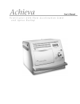
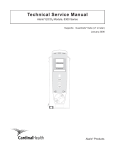
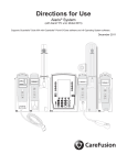
MEDLEY™
MONITOR
STAND
B
Y
MEDICATION SAFETY SYSTEM
SpO2 MODULE
Model 8220
SpO2 Module
M
ALAR
% SpO2
PULSE (BPM)
CHANNEL
SELECT
CHANNEL
OFF
MONITOR
DIRECTIONS FOR USE
MODEL 8220
SpO2 MODULE
TABLE OF CONTENTS
INTRODUCTION
1
3
4
5
GETTING STARTED
7
12
13
14
14
14
15
17
17
23
26
DEFINITIONS . . . . . . . . . . . . . . . . . . . . . . . . . . . . . . . . . . . . . . . . . . . . . . . . . . . . . . . . . . . . . . . . . . . . . . . . . . . . . . . . . . . . . . . . . . . . . . . . . .
AUDIO CHARACTERISTICS . . . . . . . . . . . . . . . . . . . . . . . . . . . . . . . . . . . . . . . . . . . . . . . . . . . . . . . . . . . . . . . . . . . . . . . . . . . . . . . . . . .
ALARMS . . . . . . . . . . . . . . . . . . . . . . . . . . . . . . . . . . . . . . . . . . . . . . . . . . . . . . . . . . . . . . . . . . . . . . . . . . . . . . . . . . . . . . . . . . . . . . . . . . . . . . .
ADVISORIES . . . . . . . . . . . . . . . . . . . . . . . . . . . . . . . . . . . . . . . . . . . . . . . . . . . . . . . . . . . . . . . . . . . . . . . . . . . . . . . . . . . . . . . . . . . . . . . . . . .
27
28
29
30
MAINTENANCE
31
33
34
35
36
37
APPENDIX
ACCESSORIES
.................................................................................................
39
MAINTENANCE
SPECIFICATIONS . . . . . . . . . . . . . . . . . . . . . . . . . . . . . . . . . . . . . . . . . . . . . . . . . . . . . . . . . . . . . . . . . . . . . . . . . . . . . . . . . . . . . . . . . . . . . .
CONFIGURABLE SETTINGS . . . . . . . . . . . . . . . . . . . . . . . . . . . . . . . . . . . . . . . . . . . . . . . . . . . . . . . . . . . . . . . . . . . . . . . . . . . . . . . . . .
INSTRUMENT CLEANING . . . . . . . . . . . . . . . . . . . . . . . . . . . . . . . . . . . . . . . . . . . . . . . . . . . . . . . . . . . . . . . . . . . . . . . . . . . . . . . . . . . .
INSPECTION REQUIREMENTS . . . . . . . . . . . . . . . . . . . . . . . . . . . . . . . . . . . . . . . . . . . . . . . . . . . . . . . . . . . . . . . . . . . . . . . . . . . . . . .
SERVICE INFORMATION . . . . . . . . . . . . . . . . . . . . . . . . . . . . . . . . . . . . . . . . . . . . . . . . . . . . . . . . . . . . . . . . . . . . . . . . . . . . . . . . . . . . .
WARRANTY . . . . . . . . . . . . . . . . . . . . . . . . . . . . . . . . . . . . . . . . . . . . . . . . . . . . . . . . . . . . . . . . . . . . . . . . . . . . . . . . . . . . . . . . . . . . . . . . . . .
ALARMS, ADVISORIES
AND PROMPTS
ALARMS, ADVISORIES AND PROMPTS
GETTING STARTED
WARNINGS AND CAUTIONS . . . . . . . . . . . . . . . . . . . . . . . . . . . . . . . . . . . . . . . . . . . . . . . . . . . . . . . . . . . . . . . . . . . . . . . . . . . . . . . .
MEASUREMENTS . . . . . . . . . . . . . . . . . . . . . . . . . . . . . . . . . . . . . . . . . . . . . . . . . . . . . . . . . . . . . . . . . . . . . . . . . . . . . . . . . . . . . . . . . . . . .
CONTROLS AND INDICATORS . . . . . . . . . . . . . . . . . . . . . . . . . . . . . . . . . . . . . . . . . . . . . . . . . . . . . . . . . . . . . . . . . . . . . . . . . . . . . .
INSTALLATION PROCEDURE . . . . . . . . . . . . . . . . . . . . . . . . . . . . . . . . . . . . . . . . . . . . . . . . . . . . . . . . . . . . . . . . . . . . . . . . . . . . . . . . .
ATTACHING AND DETACHING CHANNELS . . . . . . . . . . . . . . . . . . . . . . . . . . . . . . . . . . . . . . . . . . . . . . . . . . . . . . . . . . . . . . . .
START-UP SEQUENCE . . . . . . . . . . . . . . . . . . . . . . . . . . . . . . . . . . . . . . . . . . . . . . . . . . . . . . . . . . . . . . . . . . . . . . . . . . . . . . . . . . . . . . . .
GENERAL SETUP AND USE . . . . . . . . . . . . . . . . . . . . . . . . . . . . . . . . . . . . . . . . . . . . . . . . . . . . . . . . . . . . . . . . . . . . . . . . . . . . . . . . . .
DISPLAYS . . . . . . . . . . . . . . . . . . . . . . . . . . . . . . . . . . . . . . . . . . . . . . . . . . . . . . . . . . . . . . . . . . . . . . . . . . . . . . . . . . . . . . . . . . . . . . . . . . . . . .
MONITORING MODE . . . . . . . . . . . . . . . . . . . . . . . . . . . . . . . . . . . . . . . . . . . . . . . . . . . . . . . . . . . . . . . . . . . . . . . . . . . . . . . . . . . . . . . .
SETTING CHANNEL OPTIONS . . . . . . . . . . . . . . . . . . . . . . . . . . . . . . . . . . . . . . . . . . . . . . . . . . . . . . . . . . . . . . . . . . . . . . . . . . . . . . .
POWERING OFF . . . . . . . . . . . . . . . . . . . . . . . . . . . . . . . . . . . . . . . . . . . . . . . . . . . . . . . . . . . . . . . . . . . . . . . . . . . . . . . . . . . . . . . . . . . . . . .
INTRODUCTION
ABOUT THE SYSTEM . . . . . . . . . . . . . . . . . . . . . . . . . . . . . . . . . . . . . . . . . . . . . . . . . . . . . . . . . . . . . . . . . . . . . . . . . . . . . . . . . . . . . . . . .
FEATURES . . . . . . . . . . . . . . . . . . . . . . . . . . . . . . . . . . . . . . . . . . . . . . . . . . . . . . . . . . . . . . . . . . . . . . . . . . . . . . . . . . . . . . . . . . . . . . . . . . . . .
DEFINITIONS . . . . . . . . . . . . . . . . . . . . . . . . . . . . . . . . . . . . . . . . . . . . . . . . . . . . . . . . . . . . . . . . . . . . . . . . . . . . . . . . . . . . . . . . . . . . . . . . . .
SYMBOLS . . . . . . . . . . . . . . . . . . . . . . . . . . . . . . . . . . . . . . . . . . . . . . . . . . . . . . . . . . . . . . . . . . . . . . . . . . . . . . . . . . . . . . . . . . . . . . . . . . . . . .
APPENDIX
GENERAL CONTACT INFORMATION
Customer Advocacy
For clinical and technical questions, feedback, and troubleshooting assistance.
Phone, toll-free, within the United States and Canada: (800) 854-7128, Ext. 7812
E-Mail: [email protected]
Technical Support
For technical information related to maintenance procedures and service manual support.
Phone:
(858) 458-6003
Toll-free, within the United States: (800) 854-7128, Ext. 6003
Toll-free, within Canada:
Eastern: (800) 227-7215
Western: (800) 667-2335
For more detailed information, refer to the “Service Information” section of this document.
INTRODUCTION
About the System
INTRODUCTION
The MEDLEY™ Medication Safety System is a modular infusion
and monitoring system designed to provide SpO2 monitoring
capabilities and accurate, automated infusion of a broad range
of intravascular fluids, medications and blood products.
The MEDLEY™ Medication Safety System consists of the
Programming Module (Model 8000), and detachable
MEDLEY™Modules (or “channels”) which provide infusion or
monitoring capabilities. The MEDLEY™ System is intended for
use in hospitals and healthcare facilities on adult, pediatric and
neonatal patients.
This document provides Directions for Use for the Model 8220
SpO2 Module. Please read all instructions for both the SpO2
Module and the Programming Module before using the device.
Only one SpO2 Module can be connected to a MEDLEY™
Programming Module.
The SpO2 Module is intended for continuous, noninvasive
monitoring of functional oxygen saturation of arterial
hemoglobin (SpO2) and pulse rate measured by an SpO2 sensor.
The SpO2 Module and accessories are indicated for use with
adult, pediatric and neonatal patients during both no motion
and motion conditions, and for patients who are well or poorly
perfused in hospitals and hospital-type facilities.
The MEDLEY™ System uses a wide variety of Masimo® LNOP®
series sensors and Masimo® PC series patient cables. The
Masimo® sensors and cables are designed for use with the
Model 8220 SpO2 Module. For specific directions for use, refer
to the sensor and cable packaging.
Contraindications: The MEDLEY™ SpO2 Module, with Masimo®
LNOP® series sensors and Masimo® PC series patient cables are
contraindicated for use as an apnea monitor.
INTRODUCTION 1
About the System (Continued)
Principle of Operation
The operation of the MEDLEY™ SpO2 Module is based on the
principles of pulse oximetry. Oxyhemoglobin and
deoxyhemoglobin differ in their absorption of red and infrared
light (spectrophotometry). The volume of arterial blood in tissue
and the light absorbed by the blood changes during the pulse
(plethysmography). Because oxyhemoglobin and
deoxyhemoglobin differ in light absorption, the amount of red
and infrared light absorbed by the blood is related to
hemoglobin oxygen saturation. The SpO2 Module uses the
Masimo® proprietary Signal Extraction Technology® (SET®) to
decompose the red and infrared pulsatile absorbance signal into
an arterial signal plus a noise component and its value is used to
find the SpO2 saturation in an empirically derived equation in
the Masimo® SET® software. The values in the look-up table are
based on human blood studies against a laboratory co-oximeter
on healthy adult volunteers in induced hypoxia states during
motion and nonmotion conditions.
2 INTRODUCTION
Features
To enhance safety and ease of operation, the MEDLEY™ Medication System
provides a full range of audio and visual alarms, advisories and prompts.
Fast SAT
When Fast SAT is enabled and there is one data point that is significantly
different from a previous data point, averaging is disregarded and the most
recent data point is displayed. For example, if the readings were 97%, 96%,
95% and 85%, the saturation level displayed would be 85%.
Guardrails®
Safety Software
The Guardrails® Safety System is designed to help reduce programming
errors by:
• Customizing device configurable settings to meet the need of the
selected hospital area/patient type (Profile).
• Comparing user programming with hospital-defined best practice
guidelines.
• Providing a Guardrails® Advisory prompt if an out–of–limits entry is
made.
Masimo® Sensors
Disposable and reusable sensors are available for neonatal, pediatric and
adult patients.
PI
Perfusion Index (PI) is a scaled numeric value derived from the magnitude of
the pulsations displayed on the plethysmographic (pleth) waveform. It is
calculated as a percentage of pulsatile signal to nonpulsatile signal. The PI
is used to find the best perfused site for sensor placement (the larger the PI,
the stronger the perfusion). The operating range is 0.02 to 20.0. The
desired number is >1.00 or as large as possible.
Pre-Silence
Alarms can be pre-silenced for 120 seconds. The pre-silence alarm can be
cancelled before 120 seconds are complete.
Profiles Feature
A profiles feature a unique set of device options configured to optimize
device function for a specific hospital area or patient type. A profile is
comprised of a Configuration, with device settings and defaults customized
by the user to best meet the needs of the profile area/patient type.
Sensitivity Mode
The sensitivity mode, normal or maximum, of the current monitoring
configuration is displayed in the options mode. The normal setting is used
for normal patient monitoring purposes. The maximum setting is used for
improved low perfusion performance.
SET®
Signal Extraction Technology® (SET®) uses adaptive filters to separate the
arterial signal from the nonarterial noise. SET® provides for accurate
readings under extreme conditions; such as, low perfusion and motion.
Signal I.Q.™
The Signal I.Q.™ is a visual indication of the pulsation at the sensor site.
The height of the vertical bar indicates the quality of the measured signal.
The Signal I.Q.™ is related to proper sensor application, adequate arterial
signal and intensity of motion. Use the Signal I.Q.™ to verify optimal sensor
placement.
INTRODUCTION 3
INTRODUCTION
Ease of Use Features
Definitions
% SpO2 Alarm Limits
The upper and lower saturation alarm limits are displayed.
% SpO2 Display
The functional arterial hemoglobin oxygen saturation is displayed in units of
percentage SpO2.
Limit Mode
The limit mode displays either the adult or neonatal monitoring mode.
Pleth Waveform
The plethysmographic (pleth) waveform is a graphic representation of
changes in the extremity blood volume during the events of the cardiac
cycle.
Pre-Silence
Alarms can be pre-silenced for 120 seconds. The pre-silence alarm can be
cancelled before 120 seconds are complete.
Pulse Beat Volume
Pulse beat volume can be configured to a volume level of 1, 2, 3 or off.
Pulse Rate Alarm Limits
The upper and lower pulse rate alarm limits are displayed.
Pulse Rate Display
The patient’s pulse rate is displayed in beats per minute (bpm).
Saturation Averaging Time
The averaging time of this device can be set to 2, 4, 8, 10, 12, 14 or 16
seconds.
System Configuration
The System Configuration mode provides the ability for qualified personnel
to customize device settings. If the profile feature is enabled, the system
settings defined for the selected Profile are automatically activated.
Trend Data
The trend data is a tabular display of the %SpO2 and Pulse Rate. The
display shows the alarm conditions for the time period displayed and the
average, high and low values . The data is stored for 24 hours.
4 INTRODUCTION
Symbols
Attention: Refer to accompanying documentation.
75
Consult operating instructions.
Type BF Applied Part
IPX1
Protection against fluid ingress: Drip Proof
IUI Connector: Inter-Unit Interface connector used to establish power and communications
between the Programming Module and add-on channels.
MM-YYYY
Manufacturing Date: Number adjacent to symbol indicates the month and year of
manufacture.
CAUTION: Federal (U.S.A.) law restricts this device to sale by or on the order of a physician.
INTRODUCTION 5
INTRODUCTION
+
Canadian and U.S. Certification Mark: Products bearing this mark have been tested and
certified in accordance with applicable U.S. and Canadian electrical safety and performance
standards.
T H I S PA G E
I N T E N T I O N A L LY
LEFT BLANK
6 INTRODUCTION
GETTING STARTED
NOTE: Although the MEDLEY™ System is built and tested to
exacting specifications, it is not intended to replace the supervision
of IV infusions and patient monitoring by medical personnel. The
user should become thoroughly familiar with the features and
operation of the MEDLEY™ System and exercise vigilance in its
utilization.
Definitions
GETTING STARTED
WARNING
This heading alerts the user to potential serious outcomes
(death, injury or serious adverse events) to the patient or user.
CAUTION
This heading alerts the user to take special care for the safe and
effective use of the device.
Warnings and Cautions
For WARNINGS and CAUTIONS for the Programming Module,
refer to its Directions for Use.
To ensure proper performance of the MEDLEYTM System and to
reduce potential injury, observe the following WARNINGS and
CAUTIONS:
WARNING
The SpO2 Module is NOT to be used as an apnea monitor.
WARNING
SpO2 is intended only as an adjunct in patient assessment. It
must be used in conjunction with clinical signs and symptoms.
WARNING
Pulse oximetry readings and pulse signal can be affected by
certain ambient conditions, sensor application errors and certain
patient conditions.
WARNING
Inspect the SpO2 sensor site regularly to ensure correct sensor
positioning, application and site integrity. Tissue damage could
occur over prolonged time periods, depending on the patient
profile (such as, neonates) and method of application. Refer to
the sensor instructions for additional information.
GETTING STARTED 7
Warnings and Cautions
WARNING
The SpO2 Module should be considered an early warning device.
As a trend towards patient deoxygenation is indicated, blood
samples should be analyzed by a laboratory CO-Oximeter to
completely understand the patient’s condition.
WARNING
Interfering Substances: Carboxyhemoglobin and
methemoglobin may erroneously increase readings. The level of
increase is approximately equal to the amount of
carboxyhemoglobin present. Dyes, or any substance containing
dyes, that change usual arterial pigmentation may cause
erroneous readings.
WARNING
Do not use the SpO2 Module or sensors during Magnetic
Resonance Imaging (MRI).
WARNING
The SpO2 Module is not rated for defibrillation use. Disconnect
sensor from patient or patient cable from module prior to
defibrillation.
WARNING
Carefully route patient cabling to reduce the possibility of
patient entanglement or strangulation.
WARNING
If an alarm condition on the SpO2 Module occurs while the
audio alarm is silenced, the only alarm indications will be visual
displays and symbols related to the alarm condition.
WARNING
Check alarm limits each time the SpO2 Module is used, to ensure
they are appropriate for the patient being monitored.
WARNING
Use only Masimo® approved LNOP® sensors and PC Series patient
cables with the SpO2 Module Model 8220. Use of other sensors,
transducers, cables and accessories other than those specified
may cause improper SpO2 Module performance resulting in
inaccurate readings, increased emission and/or decreased
immunity and degraded electromagnetic compatibility
performance of the SpO2 Module.
.
8 GETTING STARTED
Warnings and Cautions (Continued)
WARNING
Before use, read sensor Directions for Use, including all warnings,
cautions and instructions.
GETTING STARTED
WARNING
Do not use a sensor, cable, connector or SpO2 Module that
appears damaged. Do not use a sensor with exposed optical
components. Do not immerse or wet the sensor or cable. Clean
as per manufactures instructions, refer to LNOP® Sensors
Instructions For Use. The sensor disconnect error message and
associated alarm indicate that the sensor is either disconnected
or the wiring is faulty. Check the sensor connection and, if
necessary, replace the sensor and/or pulse oximetry cable.
WARNING
Do not lift the SpO2 Module by the cable or power cord because
the cable or cord could disconnect from the instrument, causing
it to drop on the patient. Do not place the SpO2 Module in any
position that might cause it to fall on the patient.
CAUTION
The sensor disconnect error message and associated alarm
indicate the sensor is either disconnected or the wiring is faulty.
Check the sensor connection and, if necessary, replace the
sensor and/or pulse oximetry cable.
CAUTION
To ensure Electromagnetic Compliance Integrity, accessories
including external communication systems (hospital data
communication equipment and/or Nurse call systems) must be
certified to applicable standards:
• IEC 60601-1 (Electromedical Equipment) or
• IEC 950 (Data Processing Equipment)
GETTING STARTED 9
Warnings and Cautions (Continued)
User Warnings and Cautions
To ensure proper performance of the MEDLEY™SpO2 Module
and to reduce potential injury to the operator, observe the
following WARNINGS and CAUTIONS:
WARNING
Do not open the instrument case. There are no user serviceable
parts inside. The instrument case should only be opened by
qualified service personnel using proper grounding techniques.
When the instrument case is opened, an electrical shock hazard
exists which can result in serious injury to persons and
instrument component damage.
Dropping/Jarring
Should an instrument be dropped or severely jarred, it should
be immediately taken out of use and inspected by qualified
service personnel, to ensure its proper function prior to reuse.
MON
Y
NDB
STA
R
ITO
M
AR
AL
Sp
O2
Mod
%
Sp
ule
O2
PU
®
TIE
PA
NT
CA
RE
SY
ST
LS
E (BP
M)
EM
L
NE
AN
CH LECT
SE
OR
NIT
MO
L
NE
AN
CH OFF
EM
ST
SY ON
E
SIL
ENC
OP
TIO
3
NS
6
2
8
4
TE
R
CA
NC
EL
.
0
7
CL
EN
9
5
1
EA
R
Maintenance
Disconnect from the Programming Module when performing
maintenance.
Operating Environment
Not for use in the presence of flammable anesthetics.
10 GETTING STARTED
DANGER
Explosion risk if used in the presence
of flammable anesthetics.
Warnings and Cautions (Continued)
User Warnings and Cautions (Continued)
Radio Frequency Interference
Operating the system near equipment which radiates high
energy radio frequencies (electrosurgical/cauterizing
equipment, portable radios, cellular telephones, etc.) may
cause false alarm conditions. If this happens, reposition the
device away from the source of interference or turn off the
device and manually monitor the vital parameters using an
appropriate clinical alternative.
GETTING STARTED
CAUTION
When using the SpO2 Module in combination with a
Programming Module, which is interconnected to hospital data
communications equipment and /or Nurse call systems, the
external systems must be certified to applicable standards to
insure correct operation and electromagnetic compliance
integrity.
Interconnected data communications systems must be certified
to IEC 950 (data processing equipment) or IEC 60601-1
Electromedical Equipment.
Nurse call systems must be certified to UL 1069 (Hospital
Signaling and Nurse Call Equipment) or comply with
requirements specified in IEC 60601-1.
Compliance with electromagnetic compatibility standard (IEC
60601-1-2) is a function of all interconnected equipment and
cabling and is the responsibility of the user to insure external
equipment complies with applicable EMC standards.
Failure to verify such external equipment meets applicable EMC
standards may result in degraded Electromagnetic Compatibility
(refer to Radio Frequency Interference Warning for additional
information).
GETTING STARTED 11
Measurements
If the accuracy of any measurement does not seem reasonable,
first check the patient’s vital signs by alternate means and then
check the MEDLEY™ SpO2 Module to ensure it is functioning
properly.
An inaccurate measurement may be caused by:
• Incorrect sensor application or use.
• Significant levels of dysfunctional hemoglobins; such as,
carboxyhemoglobin or methemoglobin.
• Intravascular dyes; such as, indocyanine green or methylene
blue.
• Exposure to excessive illumination; such as, a surgical lamp
(especially one with a xenon light source), bilirubin lamp,
fluorescent light, infrared heating lamp or direct sunlight.
NOTE: Exposure to excessive illumination can be corrected by
covering the sensor with a dark or opaque material.
• Prolonged and/or excessive patient movement.
• Venous pulsations.
• Placement of a sensor on an extremity with a blood pressure
cuff, arterial catheter, intravascular line or other causes of
insufficient perfusion.
• Nail aberrations, nail polish, fungus, etc. Remove the nail
polish and/or move the sensor to an unaffected site.
• Placement too close to electrosurgery equipment.
The loss of a pulse signal can occur in any of the following
situations:
• The sensor is too tight.
• Exposure to excessive illumination; such as, a surgical lamp
(especially one with a xenon light source), bilirubin lamp,
fluorescent light, infrared heating lamp or direct sunlight.
• Placement of a sensor on an extremity with a blood pressure
cuff, arterial catheter, intravascular line or other causes of
insufficient perfusion.
• The patient has hypotension, severe vasoconstriction, severe
anemia or hypothermia.
• There is arterial occlusion proximal to the sensor.
• The patient is in cardiac arrest or is in shock.
• Placement too close to electrosurgery equipment.
12 GETTING STARTED
Controls and Indicators
Status Indicators
Alarm
(red)
Monitor
(green)
Standby
(yellow)
IUI Connector, Left
IUI Connector, Right
(not visible)
A LA R M
M ON
S TA
Sp O
Pulse Rate Display
Channel Message Display
ITO R
2
ND
BY
Mod
u le
%S p
O
Pulse Bar Display
2
PU L
SE (
BP M
)
Channel Identification: A, B, C or D
Channel Select Key: When
CHA
NN
SEL EL
ECT
pressed, selects the corresponding
channel for patient monitoring and
setup.
MON
I TO
R
Monitor Key: When pressed,
CHA
NN
O FF E L
begins patient monitoring.
Channel Off Key: When pressed
and held for one second and then
released, stops the operation of that
channel, deselects that channel, and
if only that channel had been
operating, the system powers down.
Repeat for other operating channels
to power off each channel.
Channel Release Latch
Patient Cable Connector
GETTING STARTED 13
GETTING STARTED
%SpO2 Display
Installation Procedure
Instruments are tested before they are packaged for shipment.
They met the specifications listed in the Directions for Use at
that time. To ensure proper operation after shipment, it is
recommended that an incoming inspection is performed by your
facility before putting the instrument into use.
Unpacking the SpO2 Module
1.
Remove the product from its carton.
2.
Check for any loose parts.
If the product is damaged, contact ALARIS Medical Systems for
authorization to return the equipment for repair, whether
damage or malfunction is the responsibility of the carrier or of
ALARIS Medical Systems.
Attaching and Detaching Channels
Refer to the MEDLEY™ Programming Module (Model 8000)
Directions for Use for detailed instructions on attaching and
detaching channels.
Start-Up Sequence
Powering On the System
1.
Connect the MEDLEY™ Programming Module to an external
AC power source.
2.
Attach the SpO2 Module to the Programming Module.
3.
Press the SYSTEM ON key on the Programming Module.
4.
The system self test begins:
• The diagnostics test causes all LED display segments and
Status Indicator lights of the attached channel(s) to
illuminate briefly.
• Power Indicator illuminates.
• Appropriate channel identification (A, B, C or D) is
displayed on the attached channel(s).
• An Audio tone sounds.
5.
At the completion of the system-on test, the NEW PATIENT?
screen appears on the Programming Module.
14 GETTING STARTED
Start-Up Sequence (Continued)
Powering On the System (Continued)
NOTE: If any of the following conditions are observed,
Programming Module or the affected channel must be removed
from use and inspected by qualified personnel:
GETTING STARTED
• LED segments are not illuminated on the channel displays during
the system on test.
• Indicator lights do not illuminate.
• Appropriate channel identification (A, B, C or D) is not displayed.
• Audio tone does not sound.
• Main Display does not appear backlit, appears irregular, or has
evidence of a row of pixels not functioning properly. If the
affected channel operates normally when it is attached via the
alternate IUI connector, it may be used until replacement channel
can be substituted.
General Setup and Use
NOTE: Use only Masimo® LNOP® series sensors and PC series
patient cables.
1.
Attach a Masimo® patient cable to the SpO2 Module.
Ensure a secure connection and patient cable is not twisted,
sliced or frayed.
2.
Attach a Masimo® LNOP® sensor to the Masimo® patient
cable. Refer to the sensor’s directions for use for detailed
instructions.
3.
Ensure the sensor’s red LED is on.
4.
Attach sensor to patient. Refer to the sensor’s Directions
for Use for detailed instructions.
5.
Verify high and low alarm rates for SpO2 and pulse rate are
correct for patient by pressing the CHANNEL SELECT key.
NOTE: SEARCHING may appear in the Channel Message
Display until the SpO2 and pulse readings have stabilized
(approximately 15 seconds).
NOTE: If the sensor is not attached to a site after powering
up, the Module will display SENSOR OFF. If a sensor is not
attached while this message is displayed, the Module will go
into a sleep mode. To begin monitoring once the Module is in
this mode, press the MONITOR key.
6.
Monitor the patient.
GETTING STARTED 15
General Setup and Use (Continued)
7.
After patient monitoring is complete, remove the sensor
from the patient according to hospital protocol.
8.
Turn off the SpO2 Module by pressing and holding the
CHANNEL OFF key for one second.
NOTE: Channel will initiate power down when CHANNEL OFF
key is released.
16 GETTING STARTED
Displays
Main Display
Refer to the MEDLEY™ Programming Module (Model 8000)
Directions for Use for general information in the Main Display.
Title Bar
Soft Keys
A
B
SPO2
M
ALAR
MONITOR
STAND
B
Y
®
SpO2 Module
PATIENT CARE SYSTEM
% SpO2
PULSE (BPM)
CHANNEL
SELECT
SILENCE
SYSTEM
ON
OPTIONS
MONITOR
CHANNEL
OFF
1
4
2
3
5
6
7
8
9
ENTER
CLEAR
0
.
CANCEL
>Select Channel
AUDIO
ADJUST
NOTE: Throughout the following sections of this chapter, display
screens are aligned with the corresponding steps.
Monitoring Mode
Navigating Main Display
1.
Attach the SpO2 Module to the Programming Module.
2.
Power on the system by pressing the SYSTEM ON key on the
Programming Module. The NEW PATIENT? screen will
appear.
Midtown Hospital
NEW PATIENT ?
Yes
“Yes” Clears Previous
Patient Data
No
• A Yes selection clears the previous SpO2 trend data.
• A No selection retains the previous SpO2 trend data.
>Select Yes or No
DISPLAY
CONTRST
• Once a selection is made either the Main Display will
appear or, if the Guardrails® Safety Software is enabled,
the profiles screen (as shown on the right) will be
displayed.
NOTE: When Guardrails® Safety Software is enabled:
• If Yes is selected, you will be prompted to confirm the last
Profile selected.
• If No is selected, you will be prompted to choose a Profile.
Midtown Hospital
Profiles
1 of 2
Adult ICU
View
Adult General Care
View
Neonatal
View
Peds ICU
View
Neonatal ICU
View
>Select a Profile
CONFIRM
PAGE
DOWN
GETTING STARTED 17
GETTING STARTED
Channel Status
• A solid Channel Letter display
indicates channel is operating.
• An outlined Channel Letter display
indicates that the channel is
attached and ready for use.
Monitoring Mode (Continued)
Navigating Main Display (Continued)
3. Attach the patient cable and sensor as described in the
“General Setup and Use” section of this document.
Midtown Hospital
Adult ICU
A
SPO2
>Select Channel
AUDIO
ADJUST
4.
Press the CHANNEL SELECT key on the SpO2 Module to view
the SPO2 Main display.
The following information can be viewed in this display:
• limit mode (Adult or Neonatal)
• %SPO2, with high and low alarm limits
• PULSE RATE, with high and low alarm limits
• pleth waveform
• Signal I.Q.™
• PI
5.
Press the MAIN SCREEN soft key to return to the Main
Display.
A SPO2 Main
% SPO2
97
Off
90
PULSE
RATE
82
150
50
Adult
Mode
PI = 10.56
TREND
LIMITS
A
- pleth waveform
- Signal I.Q.™
- PI
MAIN
SCREEN
SPO2
>Select Channel
AUDIO
ADJUST
Setting Alarm Limits
1.
Press the CHANNEL SELECT key on the SpO2 Module.
A SPO2 Main
% SPO2
97
Off
90
PULSE
RATE
82
150
50
Adult
Mode
PI = 10.56
TREND
18 GETTING STARTED
LIMITS
MAIN
SCREEN
Monitoring Mode (Continued)
Setting Alarm Limits (Continued)
2.
Press the LIMITS soft key. The following limits can be
changed:
•
•
•
•
%SPO2 HIGH
%SPO2 LOW
PULSE HIGH
PULSE LOW
A
Adult Alarm Limits
%SPO2
HIGH
%SPO2
LOW
PULSE
HIGH
PULSE
LOW
Off
90
150
50
>Select Parameter Limit
Confirm
Press the soft key for the parameter limit being changed.
A
• Selected parameter will be highlighted.
Adult Alarm Limits
• Display will prompt for a value to be entered.
%SPO2
HIGH
%SPO2
LOW
PULSE
HIGH
PULSE
LOW
GETTING STARTED
3.
Off
90
150
50
>Enter High %SPO2 Limit
Confirm
4.
Enter a numeric value for the selected alarm limit.
NOTES:
• The %SPO2 HIGH limit can be Off or a numeric value.
Numeric values can be entered using the keypad or the
and
keys. After the field containing a valid value
has been highlighted for three seconds, the display prompt
changes to >Press ENTER to Confirm.
A
Adult Alarm Limits
%SPO2
HIGH
%SPO2
LOW
PULSE
HIGH
PULSE
LOW
Press the ENTER key on the Programming Module to
confirm.
Off
>Press ENTER to Confirm
• Pressing the Confirm soft key will cause the screen to
return to the SPO2 Main display.
5.
_98
90
150
50
Confirm
A
Adult Alarm Limits
NOTE: Once the ENTER key is pressed, the display highlights
the next limit and prompts for an entry.
%SPO2
HIGH
%SPO2
LOW
PULSE
HIGH
PULSE
LOW
98
_90
150
50
>Enter Low %SPO2 Limit
Confirm
GETTING STARTED 19
Monitoring Mode (Continued)
Setting Alarm Limits (Continued)
6.
Press the Confirm soft key to return the SPO2 Main display.
A
Adult
Mode
SPO2 Main
% SPO2
97
98
89
PULSE
RATE
82
140
55
PI = 10.56
TREND
7.
Press the MAIN SCREEN soft key to return to the Main
Display.
LIMITS
MAIN
SCREEN
Midtown Hospital
Adult ICU
A
SPO2
>Select Channel
AUDIO
ADJUST
Navigating Trend Data View
1.
Press the CHANNEL SELECT key on the SpO2 Module to view
the SPO2 Main display.
A SPO2 Main
Adult
Mode
% SPO2
97
Off
90
PULSE
RATE
82
150
50
PI = 10.56
TREND
2.
Press the TREND soft key in the SPO2 Main display to view
the Trend Data display.
NOTE: Tabular information will not be updated while the
Trend Data view is displayed. The tabular data will be
updated, using the new trend data stored in the SpO2 Module,
after leaving the Trend Data view. To view the latest data,
return to the Trend Data view.
A
MAIN
SCREEN
Adult
Mode
Trend Data
SPO2
TIME
2001-07-06 AVG
08:08:30
97
07:38:30
97
MAX
MIN
100
90
100
90
100
90
100
88
07:08:30
--97
100
90
08:38:30
97
97
09:01:17
06:38:30
PULSE
82
MAX
MIN
152
50
150
50
150
50
150
50
--82
150
50
AVG
82
82
82
ZOOM: 30min 15min 5min 1min 30sec
>Press UP/DOWN Keys
to move cursor.
PAGE
UP
20 GETTING STARTED
LIMITS
ZOOM
SPO2
Main
PAGE
DOWN
Monitoring Mode (Continued)
Navigating Trend Data View (Continued)
The following information can be viewed in the Trend Data
display:
• TIME period for data collection period
• average SPO2, with high and low values
• average PULSE rate, with high and low values
• alarm icon ( )
NOTES:
GETTING STARTED
• The
will only be displayed if a limit violation occurred
for the indicated limit in the time window.
• If there are no SPO2 or PULSE rate values for the time
period displayed, dashes (---) will be displayed.
• Six data collection periods are displayed on a screen page.
3.
Press the PAGE UP and PAGE DOWN soft keys to navigate
from page to page.
NOTE: The last page does not have a PAGE DOWN soft key
and the first page does not have a PAGE UP soft key. When
moving from page to page, the cursor always displays on the
third row of data.
4.
To move the cursor, press the
Programming Module.
or
key on the
A
08:38:30
97
97
08:08:30
97
07:38:30
97
MAX
MIN
100
90
100
90
100
90
100
88
07:08:30
--97
100
90
09:01:17
NOTE: With further
key presses, the cursor stays in this
position (as illustrated) and the data view scrolls up one row at
a time.
Adult
Mode
Trend Data
SPO2
TIME
2001-07-06 AVG
06:38:30
PULSE
82
MAX
MIN
152
50
150
50
150
50
150
50
--82
150
50
AVG
82
82
82
ZOOM: 30min 15min 5min 1min 30sec
>Press UP/DOWN Keys
to move cursor.
PAGE
UP
5.
To change the TIME period for the data collection period,
move the cursor to the desired time period and press the
ZOOM soft key.
• New time period will be highlighted in the display.
• Each press of the ZOOM soft key will change one time
period.
• Available time periods are 30 minutes, 15 minutes,
5 minutes, 1 minute and 30 seconds.
A
ZOOM
PAGE
DOWN
SPO2
Main
Adult
Mode
Trend Data
SPO2
TIME
2001-07-06 AVG
07:38:30
97
07:38:00
97
MAX
MIN
100
90
100
90
90
100
88
100
86
07:37:30
--97
100
90
07:39:00
97
97
07:39:17
07:37:00
PULSE
82
MAX
MIN
155
50
150
50
150
50
150
50
--82
150
50
AVG
82
82
82
ZOOM: 30min 15min 5min 1min 30sec
>Press UP/DOWN Keys
to move cursor.
PAGE
UP
ZOOM
SPO2
Main
PAGE
DOWN
NOTE: Repeated pressing of the ZOOM soft key will cycle
through the time period choices.
GETTING STARTED 21
Monitoring Mode (Continued)
Navigating Trend Data View (Continued)
6.
Press the SPO2 MAIN soft key to return to the SPO2 Main
display.
A
Adult
Mode
SPO2 Main
% SPO2
97
Off
90
PULSE
RATE
82
150
50
PI = 10.56
TREND
7.
Press the MAIN SCREEN soft key to return to the Main
Display.
CANCEL
SILENCE
LIMITS
MAIN
SCREEN
Midtown Hospital
Adult ICU
A
SPO2
AUDIO
ADJUST
Pre-Silencing Alarm
1. Press the SILENCE key on the Programming Module to presilence the alarm.
Midtown Hospital
Adult ICU
A
SPO2
NOTE: All monitoring alarms will be silenced for 120 seconds.
Infusion alarms will not be silenced.
AUDIO
ADJUST
2.
To Cancel the Pre-SSilence Alarm
• Press CHANNEL SELECT key on SpO2 Module.
A
Adult
Mode
SPO2 Main
% SPO2
97
Off
90
PULSE
RATE
82
150
50
• Press CANCEL SILENCE soft key to cancel the
pre-silence alarm and return to alarmable mode.
PI = 10.56
TREND
22 GETTING STARTED
CANCEL
SILENCE
LIMITS
MAIN
SCREEN
Setting Channel Options
To access and set the channel options:
1.
Press the CHANNEL SELECT key on the SpO2 Module to view
the SPO2 Main display.
A SPO2 Main
% SPO2
97
Off
90
PULSE
RATE
82
150
50
Adult
Mode
PI = 10.56
TREND
Press the OPTIONS key on the Programming Module. The
following options are available:
•
•
•
•
Limit Mode
Pulse Beep Volume
Sat. Averaging Time
Sensitivity Mode
MAIN
SCREEN
A Channel Options 1 of 1
Limit Mode:
Adult
Pulse Beep Volume: Off
Sat. Averaging Time: 8
Sensitivity Mode:
Normal
>Select an Option or
EXIT
EXIT
Changing Limit Mode
1.
2.
Press the Limit Mode soft key in the Channel Options
display.
A
Limit Mode Setup
Adult
To change the Limit Mode Setup, press either the Adult or
Neonatal soft key.
NOTE: If a Profile is being used for programming, the Limit
Mode can not be changed.
Neonatal
>Select an Option or
EXIT
EXIT
3.
If the Limit Mode is not changed, press the EXIT soft key to
return to the SPO2 Main display and press the OPTIONS key
on the Programming Module to view other options.
A SPO2 Main
% SPO2
97
Off
90
PULSE
RATE
82
150
50
Adult
Mode
PI = 10.56
TREND
LIMITS
MAIN
SCREEN
GETTING STARTED 23
GETTING STARTED
2.
LIMITS
Setting Channel Options (Continued)
Viewing or Changing Pulse Beep Volume
1.
Press the Pulse Beep Volume soft key in Channel Options
display.
A
Test
Pulse Beep Volume
Off
NOTE: The illustrated display reflects that the Pulse Beep
Volume is Off. To display the volume options, press the
Louder soft key. The selectable options are Off, Level 1,
Level 2 and Level 3.
Louder
Softer
>Press CONFIRM
Confirm
2.
To increase the volume, press Louder soft key until desired
volume level is attained. To test volume level (when not
attached to the patient), press Test soft key. To turn off
pulse beep entirely, press Off soft key.
NOTE: Audio sounds for one cycle.
A
Test
Pulse Beep Volume
Off
Louder
Softer
>Press CONFIRM
Confirm
3.
Press the Confirm soft key to return the SPO2 Main display.
A SPO2 Main
% SPO2
97
Off
90
PULSE
RATE
82
150
50
Adult
Mode
PI = 10.56
TREND
LIMITS
MAIN
SCREEN
Viewing or Changing Saturation Averaging Time
1.
Press the Saturation. Averaging Time soft key in the
Channel Options display. The selectable options are 2, 4,
8, 10, 12, 14 and 16 seconds.
NOTE: Fast SAT is enabled when 2 or 4 seconds is selected.
2.
To change the Saturation Averaging Time, press either the
Increase or Decrease soft key.
A
Saturation Averaging
Time
Increase
4 Seconds
Decrease
with
Fast SAT
>Press CONFIRM
Confirm
24 GETTING STARTED
Setting Channel Options (Continued)
Viewing or Changing Saturation Averaging Time (Continued)
3.
Press the Confirm soft key to return the SPO2 Main display.
A SPO2 Main
% SPO2
97
Off
90
PULSE
RATE
82
150
50
Adult
Mode
PI = 10.56
TREND
LIMITS
MAIN
SCREEN
1.
2.
Press the Sensitivity Mode soft key in the Channel Options
display.
A
Sensitivity Mode
Normal
To change the Sensitivity Mode, press either the Normal or
Maximum soft key.
Maximum
NOTES:
• The Normal setting is for normal patient monitoring.
• The Maximum setting is for improved low perfusion
performance.
>Select an Option or
EXIT
EXIT
• The sensitivity mode is displayed on the SPO2 Main display
only when Maximum is selected.
3.
Once a mode is chosen, the screen will return to the SPO2
Main display. Press the OPTIONS key on the Programming
Module to view other options.
A SPO2 Main
% SPO2
97
Off
90
PULSE
RATE
82
150
50
Adult
Mode
PI = 10.56
TREND
LIMITS
MAIN
SCREEN
GETTING STARTED 25
GETTING STARTED
Viewing or Changing Sensitivity Mode
Powering Off
Powering Off the System
1.
Press the MAIN SCREEN soft key to return to the Main
Display.
Midtown Hospital
Adult ICU
A
SPO2
>Select Channel
AUDIO
ADJUST
2.
Press the OPTIONS key on Programming Module.
3.
Press Power Down all Channels soft key.
System Options 1 of 2
Display Contrast
Time of Day
Power Down All Channels
Anesthesia Mode
Battery Runtime
>Select an Option or
EXIT
EXIT
4.
Press the Yes soft key.
During power off sequence, Main Display flashes Powering
Down.
Powering Off One Channel at a Time
1.
Press and hold the CHANNEL OFF key on each operating
channel for one second.
NOTE: The channel will initiate the power down at the
release of the CHANNEL OFF key.
2.
Once all attached channels are powered off, the
Programming Module automatically powers down.
During power off sequence, the Main Display flashes
Powering Down.
26 GETTING STARTED
Powering Down
PAGE
DOWN
ALARMS, ADVISORIES AND PROMPTS
Definitions
A sequence of audio and/or visual signals indicating the operating status of the
MEDLEY™ Medication Safety System. The audio may be silenced for
approximately two minutes by pressing the SILENCE key on the Programming
Module.
Alarm
An audio and visual signal that a potentially unsafe condition is present.
Immediate action is required. The audio may be silenced for approximately two
minutes by pressing the SILENCE key on the Programming Module.
Error
An audio and/or visual signal that a failure has been detected. The instrument
should be taken out of service immediately and thoroughly tested and inspected
by qualified service personnel, to ensure its proper function prior to reuse.
Prompt
An audio and/or visual signal, appearing on the bottom line of the Main Display
or the Channel Message Display, to perform some action. The audio may be
silenced for twelve seconds by pressing the SILENCE key on the Programming
Module.
Pre Silence
The alarms for the SpO2 Module can be silenced for up to 120 seconds by
pressing the SILENCE key on the Programming Module. This will not silence the
infusion alarms. To end the Pre-Silence period press the CANCEL SILENCE soft key
on the SpO2 Main display.
ALARMS, ADVISORIES AND PROMPTS 27
ALARMS, ADVISORIES
AND PROMPTS
Advisory
Audio Characteristics
The Programming Module and Main Display provide four types of alert information: advisories, prompts,
alarms and malfunctions. For more information on the Programming Module, refer to the Directions for
Use. The characteristics of the accompanying audio sounds are as follows:
WARNING
If an alarm condition on the SpO2 Module occurs while the audio alarm is silenced, the only alarm
indications will be visual displays and symbols related to the alarm condition.
Type
Sound
Notes
Advisory
One short beep every 2 seconds
Variable volume; can be silenced for
two minutes.
SpO2 Alarm (HIGH PRIORITY)
A sequence of five beeps
Variable volume; can be silenced for
two minutes.
SpO2 Alarm (LOW PRIORITY)
One long beep every 4 seconds
Variable volume; can be silenced for
two minutes.
SpO2 Error (Hardware Detected)
A single alarm tone volume
Fixed maximum decibel volume;
cannot be silenced.
SpO2 Error (Software Detected)
Pairs of long beeps
Fixed maximum decibel volume; can
be silenced for two minutes.
Illegal Key Press
Two short beeps
Key Click
One short beep
Fixed minimum volume; can be
silenced and disabled in the System
Configuration.
Prompt
One short beep every 2 seconds
Variable volume; can be silenced for
two minutes.
28 ALARMS, ADVISORIES AND PROMPTS
Variable volume; cannot be silenced.
Alarms
Alarm
Meaning
Response
Broken, unknown or nonsystem
sensor or patient cable attached.
Check sensor and patient cable.
Confirm correct sensor and patient
cable are chosen. See Accessories
for a list of sensors designed for use
with this Module.
Check Sensor - Electrical or Optical
Interference
External interference on sensor.
Check sensor. Identify source of
external interference if other than
sensor.
Check Sensor - Light
Light interference on sensor.
Check sensor. Remove or reduce
lighting. Cover or reposition sensor.
Check Sensor - Low Perfusion
Patient’s low perfusion has inhibited
monitoring.
Check sensor. Move sensor to a
better perfused site.
Check Sensor - Low Signal I.Q.
Low quality of signal being
measured.
Check sensor. Confirm correct
sensor placement. Move sensor to a
better perfused site.
High Pulse Rate Alarm
High pulse rate alarm limit has been
exceeded.
Access patient’s condition. Confirm
correct alarm limit values are
selected.
High SpO2 Alarm
High SpO2 alarm limit has been
exceeded.
Access patient’s condition. Confirm
correct alarm limit values are
selected.
Low Pulse Rate Alarm
Low pulse rate alarm limit has been
exceeded.
Access patient’s condition. Confirm
correct alarm limit values are
selected.
Low SpO2 Alarm
Low SpO2 alarm limit has been
exceeded.
Access patient’s condition. Confirm
correct alarm limit values are
selected.
No Sensor
Sensor not properly attached to
patient cable or patient cable not
properly attached to the SpO2
Module.
Attach sensor to patient cable or
attach patient cable to the SpO2
Module.
No Signal
Failure to find a patient signal after
30 seconds of searching.
Check sensor. Confirm correct
sensor placement.
Remove Module (MAX=1)
More than one SpO2 Module
attached.
Remove additional SpO2 Module.
Sensor Off
Sensor is not properly attached to
patient.
Reattach sensor to patient.
ALARMS, ADVISORIES AND PROMPTS 29
ALARMS, ADVISORIES
AND PROMPTS
Bad Sensor
Advisories
Advisory
Meaning
Response
Check Sensor - Low Perfusion
Patient’s low perfusion has inhibited
monitoring.
Check sensor. Move sensor to a
better perfused site.
Check Sensor - Low Signal I.Q.
Low quality of signal being
measured.
Check sensor. Confirm correct
sensor placement. Move sensor to a
better perfused site.
30 ALARMS, ADVISORIES AND PROMPTS
MAINTENANCE
The MEDLEY™ System Technical Service Manual is available from ALARIS Medical Systems. It includes
technical information to assist qualified service personnel in repair and maintenance of the instrument’s
repairable components. Maintenance procedures are intended to be performed only by qualified
personnel.
Specifications
Accuracy:
Pulse Rate
Saturation
25 to 240 bpm
70 - 100%
Low Perfusion1
Adults, Pediatrics
Adults, Pediatrics, Neonate
Neonate
±2 digits
±3 digits
±3 digits
Motion2, 3
Adults, Pediatrics
Adults, Pediatrics, Neonate
Neonate
No
±3 digits
±5 digits
±3 digits
Motion4
Adults, Pediatrics
Adults, Pediatrics, Neonate
Neonate
Resolution
±2 digits
±3 digits
±3 digits
1 bpm
1% SpO2
Display Update Period:
The display update period is Approximately 1 second.
Alarms:
Audible and visual alarms for high and low saturation and pulse rate, sensor condition,
system failure and low battery conditions.
LOW
HIGH
30-239 BPM
31-240 BPM
20-99%
21-100%
Alarm Limits:
Pulse Rate:
spO2
3.3"W x 8.9"H x 5.5"D
(8.4cm W x 22.6cm H x 14cm D)
Electrical Classification:
Class 1, Internally Powered Equipment, Type BF
Electronic Memory:
System configuration parameters stored in volatile memory will be retained for at least
six months by the Programming Module internal backup lithium battery. Module
specific SpO2 parameters are stored for eight hours by the Programming Module when
the system is turned off. After eight hours of continuous off time, or if the Module is
changed, the system will automatically purge Module specific information.
Environmental Conditions:
Operating
Storage/Transport
Temperature Range:
41 to 104°F
(5 to 40°C)
-4 to 140°F
(-20 to 60°C)
Relative Humidity:
20 to 90%
Noncondensing
5 to 85%
Noncondensing
Atmospheric Pressure:
525 to 4560 mmHg
(700 to 6080 hPa)
375 to 760 mmHg
(500 to 1013 hPa)
MAINTENANCE 31
MAINTENANCE
Dimensions:
Specifications (Continued)
Fluid Ingress Protection:
IPX1, Drip Proof
Measurement Range:
Perfusion
Pulse Rate
SpO2
0.02 to 20%
25 to 240 bpm
1 to 100%
Mode of Operation:
Continuous
Pulse Amplitude Display:
Pulse Amplitude Display is proportional to the height of the I.Q. signal.
Weight:
2 lbs (0.91 kg)
Specifications/Sensor
Wave length and Power: Emitted light wavelength range is within 500nm to 1000nm. Output power
does not exceed 1mW.
NOTE: Compliance to Standards
The MEDLEY™ Medication Safety System, with the Programming Module and SpO2 Module, has been assessed
and complies with the following standards: UL 2601–1, including A1 and A2; CSA C22.2 No. 601.1, including
A1 and A2; IEC/EN 60601–2–24; IEC/EN 60601–1–2 and AAMI ID26; EN 865.
NOTES:
1
The Masimo® Board performance has been validated for low perfusion accuracy in bench–top testing against a BIO-TEK®
simulator and a Masimo® simulator. Refer to service manual for more information.
2
The Masimo® Board performance has been validated for motion accuracy in human blood studies on healthy adult
volunteers in induced hypoxia studies, while performing rubbing and tapping motions at 2 to 4 Hz at an amplitude of 1 to 2
cm and a nonrepetitive range of 70-100% SpO2 against a laboratory co-oximeter and ECG monitor. This variation equals
plus or minus one standard deviation. Plus or minus one standard deviation encompasses 68% of the population.
3
The Masimo® Board performance with Masimo® LNOP® Neo and Neo Pt sensors has been validated for neonatal motion
accuracy in human blood studies on neonates, while moving the neonate’s foot at 2 to 4 Hz at an amplitude of 1 to 2 cm
against a laboratory co-oximeter and ECG monitor. This variation equals plus or minus one standard deviation. Plus or
minus one standard deviation encompasses 68% of the population.
4
The Masimo® Board performance has been validated for no motion accuracy in human blood studies on healthy adult
volunteers in induced hypoxia studies, in the range of 70-100% SpO2 against a laboratory co-oximeter and ECG monitor.
This variation equals plus or minus one standard deviation. Plus or minus one standard deviation encompasses 68% of the
population.
32 MAINTENANCE
Configurable Settings
System Settings
Feature
Default Setting
Options
Alarm Audio
Profile 1
Profile 1, 2 or 3
Battery Meter
Disabled
Enabled - Disabled
N/A
Set date and time
Key Click Audio
Enabled
Enabled - Disabled
Tamper Resist
Disabled
Enabled - Disabled
Clock Setup (Date and Time)
SpO2 Module Settings
Feature
Limit Mode
Pulse Beep Volume
Default Setting
Adult
Options
Adult or Neonatal
1
1, 2, 3 or Off
Pulse Rate Alarm Limit, High
Adult Mode: 120 bpm
Neonatal Mode: 200 bpm
31- 240 bpm
Pulse Rate Alarm Limit, Low
Adult Mode: 50 bpm
Neonatal Mode: 100 bpm
30 - 239 bpm
SpO2 Alarm Limit, High
Adult: Off
Neonatal: 95%
21 - 100%, Off
SpO2 Alarm Limit, Low
Adult: 90%
Neonatal: 80%
20 - 99%
Saturation Averaging Time
8 seconds
(Display Update Period)
Normal
MAINTENANCE
Sensitivity Mode
2, 4, 8, 10, 12, 14 or 16
seconds
Normal or Maximum
MAINTENANCE 33
Instrument Cleaning
DO NOT spray cleaning fluids directly onto the instrument or
immerse the instrument in fluids.
DO NOT use solutions containing phosphoric acid (Foamy
Q&A), aromatic solvents (naphtha, paint thinner, etc.),
chlorinated solvents*1 (Trichloroethane, MEK, Toluene,
etc.), ammonia, acetone, benzene, xylene or alcohol,
other than as specified below.
DO NOT use hard or pointed objects to clean any part of the
instrument.
Acceptable cleaning solutions are:
Warm water
Mild detergent (e.g., Manu-Klenz)
10% bleach solution (1 part bleach to 9 parts water)
Compublend II
Envirocide
2% Glutaraldehyde in water
Hydrogen Peroxide 3%
70% Isopropyl Alcohol
2% Phenols in water (O-Syl 1:128, Pheno-Cen 1:256,
Vesphene)
10% Providone Iodine (Betadine)
Quaternaries 1:512
WEX-CIDE
NOTE: All recommended solutions must be diluted per the
Manufacturer’s recommendation. After application, rinse all
surfaces with water.
1.
Keep the instrument upright and do not allow any part of
the instrument to become saturated with or submersed in
fluid during the cleaning operation.
2.
Use a soft cloth dampened with warm water and a mild
nonabrasive cleaning solution to clean all exposed surfaces.
For sanitizing or antibacterial treatment, use 10% bleach
solution and water.
NOTE: A soft-bristled brush may be used to clean hard to
reach and narrow areas. For sensor/cable cleaning, refer to
Masimo Directions for Use Manual.
®
1. Excluding 10% bleach solution in water.
34 MAINTENANCE
WARNING
Turn the instrument off and
disconnect it from the system before
cleaning. Do not spray fluids directly
onto rear case of instrument. Do not
steam autoclave, EtO sterilize,
immerse in fluids or allow fluids to
enter the case. Failure to follow
these instructions may result in an
electrical hazard.
CAUTION
The solutions/solvents identified as
NOT to be used can damage the
surfaces of the instrument.
Inspection Requirements
To ensure the system remains in good operating condition, both
regular and periodic inspections are required.
Regular inspections consist of a visual inspection for damage
and cleanliness, and performing the procedure described in the
Start–Up Sequence section of this Directions for Use before each
usage of the instrument. Regular inspections are not covered
under any contract or agreement offered by ALARIS Medical
Systems and must be performed by the user.
WARNING
Failure to perform these inspections
may result in improper instrument
operation.
Regular Inspections
PROCEDURE
FREQUENCY
Cleaning
As required
Inspect for Damage:
Case
IUI Connector
Keypad
Each usage
Each usage
Each usage
Start-Up Sequence
Each usage
Periodic inspections of the hardware are required. For detailed
instructions on performing periodic inspections and
maintenance, refer to the SpO2 Module Technical Service
Manual and supplemental service bulletins. A service agreement
may be obtained from ALARIS Medical Systems for the
performance of all required periodic inspections.
NOTE: Periodic inspections should only be performed by qualified
service personnel.
PROCEDURE
FREQUENCY
Alarm Test
12 months
Channel Identification Test
12 months
Channel Operation Test
12 months
Functional Test
12 months
Keyboard Test
12 months
Patient Lead Electrical
Leakage Test
12 months
MAINTENANCE
Preventive Maintenance Inspections
MAINTENANCE 35
Service Information
NOTE: If the instrument shows evidence of damage in transit,
notify the carrier’s agent immediately. Do not return damaged
equipment to the factory before the carrier’s agent has authorized
repairs.
If the instrument fails to respond as described in this document
and the cause cannot be determined, do not use the instrument.
Contact qualified ALARIS Medical Systems® service personnel.
Customer Service
Within the United States and Canada, information or assistance
may be obtained by calling one of the following Customer
Service toll–free numbers:
United States:
Canada:
Eastern
Western
WARNING
Instruments returned from the service
depot to your facility may be set to
factory defaults and not have a
hospital-defined data set loaded.
Biomedical personnel in the facility
are responsible for checking-in the
instrument and ensuring the current
hospital-approved data set is loaded.
(800) 482-4822
(800) 908-9918
(800) 908-9919
Technical Support
Technical Support can be contacted by calling one of the
following toll–free numbers:
United States:
Canada:
Eastern
Western
Outside the United States and Canada, service information,
applications, and manuals may be obtained by contacting your
local ALARIS Medical Systems® Service Department or distribution
center.
When submitting any request for service, include:
• a description of difficulty experienced
• Programming Module serial number, and description and
serial number of all attached channels
• administration set/lot number
• solution(s) used
• message displayed at time of difficulty
Product Return
If it is necessary to return the instrument for service, obtain a
return authorization number prior to shipment. Carefully
package the instrument (preferably in the original packaging),
reference the return authorization information, and return it to
the appropriate service or distribution center. ALARIS Medical
Systems does not assume any responsibility for loss of, or
damage to, returned instruments while in transit.
36 MAINTENANCE
(800) 854-7128, extension 6003
(800) 227-7215
(800) 667-2335
WARRANTY
ALARIS Medical Systems, Inc., (hereinafter referred to as “ALARIS Medical Systems”) warrants that:
A. Each new ALARIS Medical Systems MEDLEY™ Medication Safety System is free from defects in
material and workmanship under normal use and service for a period of one (1) year from the
date of delivery by ALARIS Medical Systems to the original purchaser.
B. Each new accessory is free from defects in material and workmanship under normal use and
service for a period of ninety (90) days from the date of delivery by ALARIS Medical Systems to the
original purchaser.
If any product requires service during the applicable warranty period, the purchaser should
communicate directly with the relevant account representative to determine the appropriate repair
facility. Except as provided otherwise in this warranty, repair or replacement will be carried out at
ALARIS Medical Systems’ expense. The product requiring service should be returned promptly,
properly packaged and postage prepaid by purchaser. Loss or damage in return shipment to the
repair facility shall be at purchaser’s risk.
In no event shall ALARIS Medical Systems be liable for any incidental, indirect or consequential
damages in connection with the purchase or use of any ALARIS Medical Systems product. This
warranty shall apply solely to the original purchaser. This warranty shall not apply to any subsequent
owner or holder of the product. Furthermore, this warranty shall not apply to, and ALARIS Medical
Systems shall not be responsible for, any loss or damage arising in connection with the purchase or
use of any ALARIS Medical Systems product which has been:
(a) repaired by anyone other than an authorized ALARIS Medical Systems service representative;
(b) altered in any way so as to affect, in ALARIS Medical Systems’ judgment, the product’s stability or
reliability;
(c) subjected to misuse or negligence or accident, or which has had the product’s serial or lot number
altered, effaced or removed;
or
This warranty is in lieu of all other warranties, express or implied, and of all other obligations or
liabilities of ALARIS Medical Systems, and ALARIS Medical Systems does not give or grant, directly or
indirectly, the authority to any representative or other person to assume on behalf of ALARIS Medical
Systems any other liability in connection with the sale or use of ALARIS Medical Systems products.
ALARIS Medical Systems DISCLAIMS ALL OTHER WARRANTIES, EXPRESS OR IMPLIED, INCLUDING ANY
WARRANTY OF MERCHANTABILITY OR OF FITNESS FOR A PARTICULAR PURPOSE OR APPLICATION.
See packing inserts for international warranty, if applicable.
MAINTENANCE 37
MAINTENANCE
(d) improperly maintained or used in any manner other than in accordance with the written
instructions furnished by ALARIS Medical Systems.
T H I S PA G E
I N T E N T I O N A L LY
LEFT BLANK
38 MAINTENANCE
APPENDIX
Accessories
This section covers the use and cleaning of Masimo® LNOP®
sensors and Masimo® SET® patient cables.
Masimo® LNOP® Sensors
NOTES:
• Before use, carefully read the LNOP® sensor Directions for Use.
• Use only Masimo® oximetry sensors for SpO2 Module
measurements. Other oxygen transducers (sensors) may cause
improper SpO2 Module performance.
Selecting a Masimo® LNOP® Sensor:
When selecting a sensor, consider the patient’s weight, the
adequacy of perfusion, the available sensor sites and the
duration of monitoring. For more information, refer to the
following table or contact your Masimo® Sales Representative.
Use only Masimo® SET® sensors. Select an appropriate sensor,
apply it as directed, and observe all warnings and cautions
presented in the directions for use accompanying the sensor.
Clean and remove any substances (such as nail polish) from the
application site. Periodically check to ensure the sensor remains
properly positioned on the patient.
High ambient light sources; (such as, surgical lights especially
those with a xenon light source, bilirubin lamps, fluorescent
light, infrared heating lamps and direct sunlight), can interfere
with the performance of an SpO2 sensor. To prevent
interference from ambient light, ensure that the sensor is
properly applied and, if required, cover the sensor site with
opaque material.
WARNING
Inspect the SpO2 sensor site regularly
to ensure correct sensor positioning,
application and site integrity. Tissue
damage could occur over prolonged
time periods, depending on the
patient profile (such as neonates) and
method of application. (Refer to the
sensor instructions for additional
information.)
CAUTION
• Do not use damaged sensors. Do
not use a sensor with exposed
optical or electrical components.
• Always remove the sensor from
the patient and completely
disconnect the patient from the
SpO2 Module before bathing the
patient.
CAUTION
Failure to take this precaution in high
ambient light conditions may result in
inaccurate measurements.
APPENDIX
APPENDIX 39
Accessories (Continued)
Masimo® Sensors (Continued)
The following sensors are available for use with the SpO2 Module:
Masimo® Single Patient
SpO2 Adhesive Sensors
Model
Patient Size
Site Inspection Interval
LNOP®-Adt
1001
> 30 Kg
Check sensor site every
8 hours and as necessary
LNOP®-Pdt
1025
> 10 Kg < 50 Kg
---
LNOP®-Neo
1002
<10 Kg
---
LNOP®-NeoPt
1003
< 1 Kg
---
Masimo Reusable
SpO2 Sensor
Masimo
Part#
Patient Size
Site Inspection Interval
LNOP®-DCI
1269
30 Kg
Check and move sensor
to new site every 4 hours.
LNOP®-DCIP
1276
10 Kg < 50 Kg
---
LNOP®-YI, Multisite
Reusable Sensor
1544
1 Kg
---
LNOP®-EAR, Ear Reusable
Sensor w/Ear Hanger
1399
> 30 Kg
---
40 APPENDIX
Accessories (Continued)
Masimo® LNOP® Sensors (Continued)
Cleaning a Masimo® LNOP® Sensor:
Reusable sensors can be cleaned, as follows:
NOTE: To avoid contamination, clean sensors before each use.
1.
Remove the sensor from the patient.
2.
Disconnect the sensor from the SpO2 Module.
3.
Wipe the sensor clean with a 70% isopropyl alcohol pad.
4.
Allow the sensor to air dry before returning it to use.
CAUTION
Do not immerse in water, solvents or
cleaning solutions. Do not sterilize by
irradiation, steam autoclave or
ethylene oxide. The sensors and
connectors are not waterproof.
(Refer to the cleaning instructions in
the Directions for Use for the
reusable Masimo® LNOP® sensors.)
Reattaching a Single Use Masimo® LNOP® Sensor:
• LNOP® single use sensors may be reattached to the same
patient if the emitter and detector windows are clear and the
adhesive still adheres to the skin.
• The adhesive can be partially rejuvenated by wiping it with an
alcohol wipe and allowing it to thoroughly air dry prior to
reattaching it to the patient.
NOTE: If the sensor fails to track the pulse consistently, the sensor
may be incorrectly positioned. Reposition the sensor or choose a
different monitoring site.
Masimo® SET® Patient Cables
Reusable patient cables of various lengths are available. All
cables that display the Masimo® SET® logo are designed to work
with any Masimo® LNOP® sensor and with any SpO2 Module
displaying the Masimo® SET® logo.
Cleaning a
Masimo®
SET®
Patient Cable:
Patient cables can be cleaned, as follows:
Remove the cable from the sensor.
2.
Disconnect the cable from the SpO2 Module.
3.
Wipe the cable clean with a 70% isopropyl alcohol pad.
4.
Allow the cable to air dry before returning it to use.
• Carefully route patient cables to
reduce the possibility of patient
entanglement or strangulation.
• Do not lift the SpO2 Module by
the patient cable.
• Do not use damaged patient
cables.
CAUTION
Do not immerse in water, solvents or
cleaning solutions. Do not sterilize by
irradiation, steam autoclave or
ethylene oxide. The patient cable
connectors are not waterproof.
(Refer to the cleaning instructions in
the Directions for Use for the
reusable Masimo® patient cables.)
APPENDIX 41
APPENDIX
1.
CAUTIONS:
T H I S PA G E
I N T E N T I O N A L LY
LEFT BLANK
42 APPENDIX
®
ALARIS Medical Systems, Inc.
10221 Wateridge Circle
San Diego, California 92121 U.S.A.
Mail:
P.O. Box 85335
San Diego, California 92186-5335 U.S.A.
ALARIS Medical Systems®, Guardrails® and MEDLEY™ are trademarks and registered trademarks of ALARIS Medical Systems, Inc. Masimo®, DCI™,
LNOP®, SET®, Signal Extraction Technology® and Signal I.Q.™ are trademarks and registered trademarks of Masimo Corporation.
All other trademarks belong to their respective owners.
ALARIS® U.S. Patent Nos. 5,601,445; 5,713,856; 5,800,387; 5,836,910; 5,941,846; Australia Patent Nos. 693,662; 703,178; 719,254; Israel
Patent No. 117,128; Taiwan Patent No. NI-107,963; Other U.S. and Foreign Patents Issued and Pending.
Masimo® U.S. Patent Nos. 5,482,036; 5,490,505; 5,632,272; 5,685,299; 5,758,644; 5,769,785; 6,002,952; 6,036,642; 6,067,462; 6,157,850;
6,206,830; and international equivalents.
147421-002
Copyright© 2001 ALARIS Medical Systems, Inc.
All rights reserved.