1
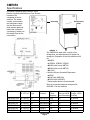
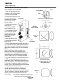
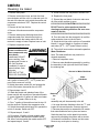
CME650
Introduction
To the owner or user: This service manual is
intended to provide you, and the maintenance or
service technician, with the information needed to
install, start up, clean, maintain and repair this
product.
The refrigeration system uses HP62 as the
refrigerant. HP62 models use polyolester
refrigerant oil.
Information on HP62 is located on page 22.
The CME650 is an ice machine that produces
cubed ice on 4 vertical cube freezing surfaces. The
ice falls as vertical strips of cubes into the ice
storage bin where they break up into individual
cubes. The CME650 automatically maintains the
level of ice by turning on when the ice level falls,
and switches off when the bin is full.
Table of Contents
Specifications . . . . . . . . . . . . . . . . . . . . . . . . . . . . . . . . . . . . . . . . . . . . . . . . page 2
Limitations
. . . . . . . . . . . . . . . . . . . . . . . . . . . . . . . . . . . . . . . . . . . . . . . . . page 3
Installation
. . . . . . . . . . . . . . . . . . . . . . . . . . . . . . . . . . . . . . . . . . . . . . . . . page 4
Plumbing . . . . . . . . . . . . . . . . . . . . . . . . . . . . . . . . . . . . . . . . . . . . . . . . . . page 6
Electrical . . . . . . . . . . . . . . . . . . . . . . . . . . . . . . . . . . . . . . . . . . . . . . . . . . . page 7
Final Check List
. . . . . . . . . . . . . . . . . . . . . . . . . . . . . . . . . . . . . . . . . . . . . . page 8
Component Location . . . . . . . . . . . . . . . . . . . . . . . . . . . . . . . . . . . . . . . . . . . . page 9
Initial Start Up . . . . . . . . . . . . . . . . . . . . . . . . . . . . . . . . . . . . . . . . . . . . . . . . page 10
Electrical Sequence
Cleaning
. . . . . . . . . . . . . . . . . . . . . . . . . . . . . . . . . . . . . . . . . . . . page 11
. . . . . . . . . . . . . . . . . . . . . . . . . . . . . . . . . . . . . . . . . . . . . . . . . . page 12
Water/ Refrigeration Schematic
. . . . . . . . . . . . . . . . . . . . . . . . . . . . . . . . . . . . . . page 15
Technical Characteristics . . . . . . . . . . . . . . . . . . . . . . . . . . . . . . . . . . . . . . . . . . page 17
Service Diagnosis
. . . . . . . . . . . . . . . . . . . . . . . . . . . . . . . . . . . . . . . . . . . . . page 18
Removal and Replacement
. . . . . . . . . . . . . . . . . . . . . . . . . . . . . . . . . . . . . . . . page 20
Parts lists and wiring diagrams are located in the
center of this manual, printed on yellow paper.
Note the warning symbol where it appears in this
manual.
It is an alert for important safety information on a
hazard that might cause serious injury.
Keep this manual for future reference.
This manual was printed on recycled paper.
October 1994
Page 1
CME650
Specifications
Information regarding Model Number, Serial
Number, Ampacity and Maximum Fuse Size are
located on the
nameplate of the ice
machine. The model
number, serial number
and refrigerant charge
are also listed on the
serial number plate just
behind the front panel.
Nameplate
Serial Number
Plate
If recharging, always use
the charge listed on the
ice machine.
CME650 Cabinet
The CME650 will stack onto a variety of ice
storage bins, see sales literature for proper ice
storage bin. Examples of bins this machine will fit
are:
• *BH550
• *HTB500, HTB350, HTB250
• BH800 (with bin top KBT23)
• BH900 (with bin top KBT22)
• BH1360
It will also fit these Scotsman Dispensers:
• CD200
• IS150 (with KADCM1)
• RS150 (with KADCM1)
* These smaller bins are recommended.
There is an optional stainless steel panel kit,
SPKCMD-1, for this machine.
Specifications:
Model Number
Dimensions Condenser Basic
W" x D" x H" Type
Electrical
CME650AE-32A
CME650WE-32A
CME650AE-3A
CME650WE-3A
CME650AE-6A
CME650WE-6A
30 x 24 x 27
30 x 24 x 27
30 x 24 x 27
30 x 24 x 27
30 x 24 x 27
30 x 24 x 27
Air
Water
Air
Water
Air
Water
208-230/60/1
208-230/60/1
208-230/60/3
208-230/60/3
230/50/1
230/50/1
August 1994
Page 2
Minimum
Circuit
Ampacity
13.6
12.7
6.6
5.8
n/a
n/a
Maximum Fuse
Size (or HACR
circuit breakers)
20
20
15
15
n/a
n/a
Refrigerant
Charge. HP62
(R-404a)
36 ounces
26 ounces
36 ounces
26 ounces
36 ounces
26 ounces
CME650
For The Installer: Environmental Limitations
The ice machine must be installed indoors in a
controlled environment.
Minimum
Maximum
Air Temp
0
50 F.
1000F.
Water Temp
400F.
1000F.
Water Pressure
20 PSI
80 PSI
Voltage
198
253
Operating the ice machine outside of the above
limitations, or outdoors, is potentially damaging to
the machine, and it is misuse of the machine. This
may void the warranty.
Scotsman Ice Systems are designed and
manufactured with the highest regard for safety
and performance. They meet or exceed the
standards of UL, NSF, and CSA.
Scotsman assumes no liability or responsibility of
any kind for products manufactured by Scotsman
that have been altered in any way, including the
use of any part and/or other components not
specifically approved by Scotsman.
Scotsman reserves the right to make design
changes and/or improvements at any time.
Specifications and design are subject to change
without notice.
Airflow on air cooled models is:
• Intake through the right side grill.
• Exhaust through the left side grill.
Do not install where this air flow is obstructed. A
clearance of 6 inches is required at the back and
sides.
October 1994
Page 3
CME650
Installation
Water
The water supply for this ice machine has been in
contact with many materials since it fell from the
sky as rain. All rain is slightly acidic, and tends to
dissolve the materials it comes in contact with.
During water’s journey to the ice machine, it has
flowed over and through the ground, been picked
up by a municipal or private pump, forced through
a series of pipes of differing construction and may
have been treated by the municipality providing
the water.
The water supplied to this ice machine will then
contain a variety of substances that will likely show
up as solids during the ice making process. These
solids are similar to those found when water is
boiled out of a saucepan. Only the water boils
away, and the minerals that were in the water
solidify in the pan. During ice making only the
water is frozen into ice, the minerals stay behind in
the reservoir. This machine pumps out the water in
the reservoir every cycle to minimize the amount of
minerals in the water system, but after time the
minerals will appear and have to be dissolved by
ice machine cleaner, then flushed away during the
cleaning process.
Air cooled models blow air in and out through the
grills at the sides (in the right and out the left).
Space is required for air flow at the sides and utility
connections at the back.
The ice machine is not designed for outdoor
use. It must be installed indoors, in a
controlled environment. The air and water
temperatures must not exceed rated limits.
Pre-installation:
1. Inspect the place where the ice machine is to be
installed. Check for:
• space for the cabinet,
• water supply,
• drain availability
• and electrical power supply.
No extension cords are allowed. The building drain
inlet must be lower than the drain outlet of the ice
bin. The water supply must have a hand shut off
valve accessible when the unit is installed.
An ice machine is a food manufacturing plant; it
takes a raw material, in this case water, and
transforms it into a food product, ice. The purity of
the water is very important in obtaining pure ice
and in maximizing product life.
The water to the ice machine should be filtered.
Water filters vary greatly in ability and function.
Install one that filters out suspended solids to a
dimension of 5 microns or less. The finer the filter
the better, but finer filters may plug-up sooner than
course ones. It may be necessary to add a course
filter ahead of the fine filter to prolong filter life.
Have the water tested. Acidic water or alkaline
water will both cause corrosion. Dissolved solids
cannot be filtered out. Check with a water
treatment specialist regarding testing, treatment
and filters.
August 1994
Page 4
CME650
Installation
Assembly:
Bin Thermostat
Installation
1. Attach the legs, or optional casters, onto the ice
storage bin. Units that are stacked should only use
legs, not casters.
2. Place the ice machine onto the storage bin.
Thermostat
Capillary Tube
3. Line up the ice machine, check that there is a
good seal between the ice machine and the
storage bin.
4. If on a Scotsman bin, attach the ice machine to
the bin using the straps and bolts shipped with the
ice machine. If on another brand bin, follow the
directions included with that bin.
Bin Thermostat
Bracket
Bin Thermostat Installation:
1. Remove rubber cap from the end of the
thermostat bracket.
2. Attach the bin thermostat bracket to the bottom
of the ice machine using the thumb screws
provided. There are pre-drilled and tapped holes
located just behind the cube drop area. The end of
the bin thermostat bracket with the plastic tubing
on it will fit into the hole in the base of the machine.
Stacking
3. Locate and uncoil a portion of the bin thermostat
capillary tube. Route the end of the capillary tube
into and through the bin thermostat bracket tube. It
should be inserted the full length of the tube, but
not past the end.
Stacking:
This machine will stack onto any CM250,
CME250, CM450, CM500, CME500, CM650 or
CME650 with the same cabinet depth (24").
Capillary Tube
1. Remove and discard the top panel from the
lower unit.
Strap
Routing Hole
2. Carefully lift the uncrated top unit onto the
bottom unit. Use of a mechanical lift is
recommended for this step.
3. Align the two ice maker cabinets.
4. Secure the top unit to the bottom one with the
hardware and straps shipped with the upper
machine.
5. Locate and uncoil all of the bin thermostat
capillary tube.
6. Route the bin thermostat capillary tube from the
upper unit, through the hole in the back of the
reservoir, through the lower unit and into the bin
thermostat bracket. Discard upper unit bracket.
October 1994
Page 5
Reservoir
Bin Thermostat Bracket
CME650
Installation
For The Plumber
1. Connect cold potable water to the 3/8" male
flare at the back of the cabinet. A water filter is
recommended. Flush the water line prior to
connecting to the ice machine.
Drain tube material must be rigid and meet local
code.
If water cooled, connect a separate water inlet line
to the water cooled condenser inlet fitting. It should
also have a hand shut off valve.
The bin drain must be vented if there is a long
horizontal run (5’ or more). The reservoir drain
must be vented and not connected to the bin drain.
All drains are gravity, and must have a minimum
fall of 1/4" per foot of horizontal run. The water
cooled condenser drain is not vented, and is
routed separately.
Traps in the bin drain line without vents ahead of
them will cause poor draining.
A loop of copper tubing may be used between the
ice machine and the water supply. This will allow
the ice machine to be pulled out from its installed
location without disconnecting the water line. No
back-flow preventer should be needed in the inlet
potable water line because provision for that is
incorporated in this N.S.F. listed product (the tube
from the inlet water valve has an air break in it, is
above the reservoir wall and cannot siphon).
2. Connect a drain tube to each drain. The drain
tubes from these connections must be run
separately. There are two connections, one is the
bin drain and the other is the reservoir drain. The
reservoir drain is a 3/4" F.P.T. brass fitting.
Maintain the air gap required by local code
between the end of the drain tubes and the
building drain receptacle.
Note: Drain tubing should be insulated to prevent
condensation from forming on the tubing.
CONFORM TO ALL LOCAL CODES
3/8" FPT Inlet
3/8 Male Flare
Water Inlet
1/2" FPT
Outlet
Water Shut
Off Valve
Water Cooled
Condenser Plumbing
Connections
Ice Storage Bin
(Typical)
Reservoir Drain
3/4" FPT, Must Be Vented.
Bin Drain. May Be Routed From
The Bottom On Some Model
Bins. Fitting May Be Plastic.
DO NOT OVERHEAT.
Water Supply and Drain Connections
August 1994
Page 6
CME650
Installation
For The Electrician
This unit must be on a separate power supply. The
maximum fuse size for this circuit is listed on the
nameplate, and per the nameplate use fuses, or
HACR circuit breakers.
Electrical connections are made at the rear of the
ice maker, inside the junction box.
Recommendation: If using wire nuts, cut off the
"tinned" ends of the wires and strip off 1/2" of
insulation from the end of the wires so there is a
copper to copper connection.
Follow All Local Codes - This Unit Must Be
Grounded. Usually a licensed electrician will be
required to connect the electrical service.
Hand Disconnect Switch
Junction Box
October 1994
Page 7
CME650
After Utility Connections
1. Level the cabinet, use the leg levelers on the
end of the legs to adjust the cabinet height. (Legs
should have been installed when the bin was
unpacked).
2. Wash out the bin. If desired, the interior of the
bin could be sanitized.
Final Check List
1. Is the ice maker cabinet in a room where
ambient temperatures are within the minimum and
maximum temperatures specified?
2. Has the water supply been connected?
3. Is the water pressure adequate?
4. Have the water connections been checked for
water leaks?
5. Have the drain connections been made?
6. Have the drain connections been checked for
leaks?
7. Is the cabinet level?
8. Is the ice machine connected to a 208-230 volt
electrical power supply and is the ice machine the
only load on that circuit?
9. Has all of the shipping material been removed
from the inside of the cabinet?
10. Has the bin thermostat bracket been attached
to the bottom of the ice machine, and the capillary
tube routed thru the bracket?
11. Has the bin and cabinet been wiped clean and
sanitized?
12. Has the Customer Evaluation & Warranty
Registration form been properly filled out? Check
for correct model and serial numbers from the
nameplate, then mail the completed form to
Scotsman.
13. Has the owner/user been given the name and
telephone number of the authorized Scotsman
Service Agency serving that location?
August 1994
Page 8
CME650
Component Location
The ice machine is designed for front service.
Many components are serviceable from the front
without removing the side panels.
Behind the front panel:
• Water pump
• Inlet water valve
• Reservoir
• Evaporators
• Water distributor
• Control box with cube size control adjustment
• ON/OFF switch
• Compressor switch
Inside the control box is control system for the ice
machine.
Timer
Cube Size Control
Master Switch
Water
Distributors
Compressor Switch
Bin Thermostat
Control Box
Overflow
Standpipe
Bin Thermostat
Drain Trough
Bin Thermostat Bracket
Water Pump
Water Inlet Valve
Component Location
October 1994
Page 9
CME650
Initial Start Up
After the final check list has been gone through,
the ice machine may be started up.
Cam Follower
1. Open the water shut off valve.
2. Switch on the electrical power.
Timer
Cam
2. Remove the front panel.
4. Remove the control box cover.
5. Locate the timer and
rotate the cam clockwise
until the timer is in the
Harvest Position.
Control Box
Timer Shown In Harvest Position
Harvest
6. Switch the compressor
switch to OFF.
3. Locate the ON/OFF
switch, switch it to ON.
4. The inlet water valve will
open, and water will flow
into the reservoir. The
water pump will begin to
pump water over the
evaporators.
Cube Size
Control Knob
Freeze
Cubes Too
Thick
5. Allow the reservoir to fill.
6. Switch the compressor
switch to ON.
Bin
Thermostat
7. On air cooled models the fan motor will begin to
turn, and warm air will be discharged from the left
side of the ice machine. On water cooled models
warm water will begin to flow from the condenser
drain.
Note: To optimize the balance between ice
production and water use, the water cooled
discharge pressure must be 245 P.S.I.G. Check
discharge pressure and adjust water regulating
valve to obtain 245 P.S.I.G. discharge pressure.
8. The water temperature in the reservoir will soon
be 320F., and ice should begin to form on the
evaporators. Note: In some cases some slush will
form in the reservoir. This is temporary and normal.
9. Allow the ice machine to operate for about 18
minutes. The ice should be fully formed and should
be harvested within a few minutes.
10. After harvest, check the ice cube size. If
needed, adjust the cube size by rotating the
adjustment knob of the cube size control. Rotate it
1/8 turn clockwise to make the cubes thicker, and
rotate it 1/8 turn counterclockwise to make the
cubes thinner.
The machine is designed to only harvest
cubes that are the correct thickness.
August 1994
Page 10
Correct Size & Shape
Ice batch weight per cycle
will be about 5.5 lb.
Cubes Too
Thin
CME650
Initial Start Up
11. Check harvest time. The machine will have
to harvest all of the cubes before it goes back
into the freeze cycle.
Timer
Cam Follower
Cam
Timer Shown In Harvest Position
Harvest
Freeze
Increase the Harvest Time if there is less than 15
seconds of harvest time after the last cube has
fallen into the bin. The machine ships set at 2 2⁄3
minutes of harvest time.
Decrease the Harvest Time if there is much more
than 15 seconds of harvest time after the last cube
has fallen into the bin. Note: Harvest time is
dependent upon the water and air temperatures at
the ice machine. Colder air and water will result in
faster ice making, but longer harvest cycles. Do
NOT adjust harvest time too short, as this will case
a freeze up of the evaporators.
Electrical Sequence:
This describes the sequence through a complete
cycle.
Freeze Cycle:
During the first part of the freeze cycle, the ice
machine compressor, fan motor if air cooled, and
water pump are operating. The relay in the middle
of the circuit board is energized.
Timed Freeze:
Cube size control closes, connecting power to the
timer motor, and after a few (4.5-5.5) minutes this
timer opens the circuit to the relay on the circuit
board. This starts the harvest cycle.
Harvest:
In the harvest cycle, the water pump and
compressor stay operating, and these two valves
are energized:
• Hot gas valve
• Inlet water valve
The unit stays in the harvest cycle until the timer
has turned the cam which has pushed the timer
micro switch button IN. If the bin thermostat is
OPEN, the ice machine will stop. If the bin
thermostat is CLOSED, the relay will energize, and
the unit will make another batch of cubes.
To Adjust Harvest Time:
1. Disconnect electrical power.
2. Locate time cam in control box.
3. Loose set screw holding the two halves of the
cam together, and rotate the front half to increase
or decrease the harvest portion of the cam (low
part).
4. Re tighten the set screw.
5. Reconnect power and check cube size of the
next cycle, as it may require adjustment after the
harvest time has been set.
12. Check operation of the bin control circuit by
holding ice on the bin control tube in the bin. This
simulates bin full and the ice machine should
switch itself off at the end of a harvest cycle.
13. Replace all the panels. The ice machine is now
ready for automatic operation..
October 1994
Page 11
CME650
Maintenance and Cleaning
Cleaning Schedule:
• Scrub the outside of the cabinet once a week
with soap and water.
• Wash off the bin door, frame and gaskets daily.
• Sanitize the bin interior once a month.
• Clean the water system and air cooled
condenser a minimum of twice per year. If in an
area of high mineral concentration in the water
supply, clean water system 4 times a year.
This ice machine will perform at its best when kept
clean. There are two areas to keep clean: The
water system including the water reservoir,
distributor tube and evaporator surface; and the
air cooled condenser filter and the condenser itself.
Inlet Water Valve Screens
If a restriction of incoming water is suspected, the
screen on the inlet side of the water valve should
be inspected & cleaned. Some models also have a
strainer in the water line; the strainer screen
should also be inspected for restricting minerals.
Air Filter (air cooled only):
1. Remove the grill on the right side of the unit.
2. Remove the filter pad from in front of the
condenser.
3. Wash the surface of the filter off with cold water,
or, if torn or so dirty it can’t be cleaned, replace
with a new filter.
4. Return the filter to its installed position.
5. Replace the grill. Do not operate the unit without
the filter in place.
Note: If the unit has been operated without the
filter in place, the fins of the condenser will
become fouled with dirt, and must be cleaned. A
vacuum cleaner with a soft brush attachment will
extract most loose dust stuck to the surface of the
condenser fins. If there is any doubt about dirt
inside the fins of the condenser, the cabinet should
be removed and a qualified service agent should
clean the condenser.
Water cooled units:
The water cooled condenser may, over time and
under certain water conditions, become internally
restricted by minerals. These will have to be
dissolved by acid or the condenser replaced. Only
a qualified service agent should attempt this type
of service.
Inlet Water Valve
Inlet Screen
August 1994
Page 12
CME650
Cleaning: Ice Storage Bin
The interior liner of the bin is in contact with a food
product: ice. The storage bin must be cleaned
regularly to maintain a sanitary environment.
Every 30 days, the liner should be sanitized with a
commercial ice machine sanitizer, according to the
directions of the sanitizer, or with a solution of
household bleach and water:
1. Mix the bleach and water using the ratio of two
ounces of bleach to two gallons of water.
Stainless Steel Components Inside Bin
The stainless steel parts in the bin also require
periodic cleaning. Chemicals in the water supply,
such as chlorine, cause brown stains to appear on
the surface of the stainless steel parts.
1. General Cleaning - staining is usually removed
by washing the parts with ordinary cleaning
powder such as Bon-Ami or Copper-Glo and
water. After cleaning, rinse with clear water.
Note: If the ice baffle was removed from the bin
during cleaning it must be reinstalled in the bin.
2. Water treatment. The chlorine enters the
machine from the municipal water supply. It can be
removed from the water supply by using a
charcoal or activated carbon water filter to treat the
water to the ice machine. If staining is severe,
filters of this type are recommended.
To Remove Scale:
Exterior Cabinet Cleaning:
1. Mix a cleaning solution of 4 ounces of Scotsman
Ice Machine Cleaner to 4 pints of hot
(950F.-1100F.) water.
The exterior cabinet may be cleaned by scrubbing
with soap and water. Do not use cleaners
containing petroleum products.
2. Using rubber gloves, dip a nylon scouring pad
into the cleaning solution and scrub the scale off
the liner.
A nylon type brush may be used to scrub stubborn
deposits.
2. Wipe all interior surfaces of the ice storage bin
with the bleach and water.
3. Allow to air dry.
3. After the scale has been removed, rinse all
surfaces inside the bin with clean, potable water.
October 1994
Page 13
CME650
Cleaning: Ice maker
1. Remove front panel.
15. Switch master and compressor switches ON.
2. Remove control box cover, and turn the timer
cam clockwise until the unit is in a harvest cycle. At
the end of the harvest cycle switch the master and
compressor switches to OFF. Replace the control
box cover.
16. Replace the front panel
3. Remove all ice from the bin.
DO NOT use ice cubes produced from the
cleaning or sanitizing solutions. Be sure none
remain in the bin.
4. Remove 4 thumbscrews and the evaporator
cover.
5. Remove water pump discharge hose from
evaporator water inlet, direct hose into bin or
bucket and switch the master switch ON until
reservoir is empty of water. Replace hose on inlet.
6. Replace evaporator cover.
Scotsman Ice Machine
Cleaner contains acids.
These compounds may
cause burns.
If swallowed, DO NOT
induce vomiting. Give
large amounts of water or
milk. Call Physician
immediately. In case of
external contact, flush
with water.
KEEP OUT OF THE
REACH OF CHILDREN.
17. Discard the next batch of cubes to make sure
all of the acid & sanitizer is gone.
/////////////////////////////////CAUTION///////////////////////////////
/////////////////////////////////////////////////////////////////////////////////
18. Pour hot water into the storage bin to melt the
cubes and also clean out the bin drain.
19. Wash the bin liner with a solution of household
bleach (1 ounce of bleach to 2 gallons of water)
and warm (95oF. - 115oF.)water. Allow to air dry.
20. The unit will now continue automatic operation.
Water Distributor:
Note: The water distributor may need to be
cleaned separately.
1. Remove evaporator cover.
2. Remove water distributor assembly by pushing
the assembly to the right until the left end clears
the retaining tab.
Removal of Water Distributor
Water
Distributor
7. Mix 8 ounces of Scotsman Ice Machine Cleaner
with 1 gallon of warm (950F. - 1150F.) water and
pour into the reservoir until full.
8. Switch the master switch ON, and operate the
unit for 20 minutes, then switch the unit OFF.
9 Repeat steps 4 and 5.
10. Wash the plastic and stainless liners of the
freezer section with a solution of household bleach
(1 ounce of bleach to 2 gallons of water) and warm
(95oF. - 115oF.) water. Allow to air dry.
1⁄
2
gallon of the solution mixed in step 10
11. Pour
into the reservoir. Replace the evaporator cover.
12. Switch the master switch back ON, operate the
unit for 5 minutes. Switch unit OFF.
Retaining
Tab
3. Lift up the left end of the water distributor
assembly and pull the assembly to the left.
4. Un-snap the water distributors from the "T", and
inspect for mineral deposits. Clean as required.
13. Repeat steps 4, 5 and 6.
5. Reverse above steps to reassemble. Be certain
that water distributors are in place and secure.
14. Pour about 1/2 gallon of clean potable water
into the reservoir, and switch the master switch
ON. After 5 minutes switch the master switch OFF
and repeat steps 4, 5 and 6.
Scale that may form on the plastic liner can be
removed by scrubbing the surface with a mixture
of Scotsman Ice Machine Cleaner and hot water.
Remove any scale prior to cleaning.
August 1994
Page 14
CME650
Refrigeration Schematic:
Freeze Cycle:
Water Schematic:
From the compressor, hot discharge gas is
pumped to the condenser, either air or water
cooled.
Water flows into the ice machine from its inlet
connection at the back of the cabinet, through the
inlet water valve and into the reservoir. The water
in the reservoir is pumped up and through the
water distributor tube at the top of the evaporators.
From there, the water flows over both sides of the
evaporators and back into the reservoir. Melted ice
and water spills into the bin flow through a drain in
the base of the bin to the exterior drain connection
at the back of the cabinet.
At the condenser, heat from the refrigerant flows
into the cooling medium, either air or water, and
the refrigerant condenses into a liquid. From the
condenser the liquid refrigerant flows through the
liquid line to the metering device, a thermostatic
expansion valve .
At the expansion valve, the liquid refrigerant
passes from a high pressure zone to one of
relatively low pressure, and in the low pressure
zone it evaporates. The low pressure zone where
the refrigerant evaporates is the evaporator. When
the refrigerant evaporates, it absorbs heat from the
metal parts of the evaporator and the water flowing
over it.
From the evaporator, the refrigerant flows back to
the compressor through the suction line.
Water Distribution
System
Hot Gas Valve
Suction Line
Liquid Line
Evaporator
Condenser
Hot Gas
Valve
Filter
Water
Pump
Inlet
Water
Valve
Fan Motor
Thermo Exp.
Valve
Water Reservoir
Discharge Line
Refrigeration Schematic
October 1994
Page 15
Compressor
Dryer
CME650
Harvest Cycle:
During the Harvest Cycle, the inlet water valve
opens, filling the reservoir and allowing the
reservoir to overflow the drain.
During the harvest cycle, the refrigerant flows from
the compressor, through the discharge line to a
branch in the line containing the Hot Gas Valve.
This valve is Open during the harvest cycle,
allowing the hot discharge gas to bypass the
condenser and enter the evaporator at its inlet.
The hot discharge gases warm up the evaporator
enough to allow the surface of the ice frozen to the
evaporator to melt. The remaining ice will then fall
off into the bin.
Water Distribution
System
Hot Gas Valve
(OPEN)
Suction Line
Liquid Line
Evaporator
Inlet
Water
Valve
(OPEN)
Condenser
Hot Gas
Valve
Filter
Water
Pump
Fan Motor
Thermo. Exp.
Valve
Water Reservoir
Discharge Line
Refrigeration Schematic
August 1994
Page 16
Compressor
Dryer
CME650
Technical Characteristics
Typical Cycle Time
• 18-19 minutes @ 90oF. air and 70oF. water
• 14-15 minutes @ 70oF. air and 50oF. water
Typical Harvest Ice Weight
• 5.5 - 6 pounds.
Typical Low Side Pressure Just Before Harvest
• Air cooled @ 70oF. air/50oF. water = 25 PSIG
• Air cooled @ 90oF. air/70oF. water = 30 PSIG
• Water cooled = 28 PSIG
Typical Freeze Cycle Air Cooled Discharge Pressure
• 300 - 350 PSIG @ 90oF. air and 70oF. water; 260 -290 @ 70oF. air and 50oF. water.
Refrigerant Charge:
• Air cooled = 36 ounces (R-404A)
• Water cooled = 26 ounces (R-404A)
Harvest Time
• Pre-set at 2 and 2⁄3 minutes. Adjustable to match field requirements.
Typical Low Side Pressure, in harvest:
• Air cooled = 80-90 PSIG Water cooled = 85 PSIG
Water Cooled Discharge Pressure, (in freeze):
• 245 PSIG
Hi Pressure Cut Out Point:
• 450 PSIG, air cooled; 400 PSIG, water cooled
Fan Pressure Switch
• 240 PSIG C.I.; 190 PSIG C.O.
Hi Temperature Cut Out Point:
• 140oF. (at hot gas valve)
Typical Compressor Amp Draw (single phase):
• 7-9 during the freeze cycle and 9-11 during the harvest cycle.
Compressor:
• Copeland: CS12K6E-PFV (single phase) or CS12K6-TF5 (three phase)
• Oil charge (included with compressor) 43 ounces of Polyolester oil
Water Inlet Valve Flow Rate:
• .75 g.p.m.
Cube Size Thermostat:
• Adjustable Cut In as needed to obtain correct cube size, C.I. range between 12oF. and -6oF
Bin Thermostat
• Adjustable; C.I. range between 38.5oF. and 43.5oF, C.O. range between 33.5 oF. and 38.5 oF
Thermostatic Expansion Valve
• Not Adjustable
October 1994
Page 17
CME650
Service Diagnosis:
SYMPTOM
No ice is made, nothing operates
No ice is made
POSSIBLE CAUSE
Unit off, due to no power
Unit off, due to master switch in
OFF position
Unit off, due to bin thermostat
open
PROBABLE FIX
Restore power
Switch master switch to ON
Check temperature at bin
thermostat bracket, if warmer
than 40o F., thermostat should be
closed. Adjust/replace thermostat.
Unit off, due to hi pressure cut out Reset and check for dirty
open
condenser, hot location, or water
interruption (if water cooled).
Unit off, due to hi temperature cut Hot gas valve leaking thru,
out open
replace hot gas valve.
Unit off, due to circuit board open Check for short circuit and
replace circuit board.
No water due to water turned off. Reconnect water supply
No water due to water filter
Replace water filter
plugged.
No water due to inlet water valve Clean out inlet screen
screen plugged
No water due to strainer screen
Clean out inlet screen
plugged
No water due to Inlet water valve Replace valve
coil open
No water due to inlet water valve Replace valve
will not open
Water in reservoir, but no water
Water pump does not work,
over evaporators
replace pump
No cooling at evaporator due to
Switch compressor on.
compressor switched off
Replace inlet water valve
No cooling at evaporator due to
too much heat load because inlet
water valve leaks thru
No cooling at evaporator due to
Replace hot gas valve
hot gas valve leaking thru
No cooling at evaporator due to
Check & replace fan motor or fan
fan not turning
control switch
No cooling at evaporator due to
Clean condenser
dirty condenser
August 1994
Page 18
CME650
Service Diagnosis
SYMPTOM
No ice is made
Makes ice, but very little
Cubes are wrong size/shape
Ice fused together in bin
Water drips on ice
POSSIBLE CAUSE
No cooling due to low refrigerant
charge
PROBABLE FIX
Locate leak, recover remaining
refrigerant, replace dryer,
evacuate and weigh in nameplate
charge.
Will not harvest due to hot gas
Check for voltage to coil in
valve not opening.
harvest, if there is voltage check
coil, if coil is ok, replace hot gas
valve
No cooling due to compressor not Check compressor for voltage,
operating
continuity, and operation.
Replace if found to be faulty.
Will not harvest due to not
Adjust harvest time longer.
enough harvest time.
Will not harvest due to lack of
Check water supply & distribution
water.
system. Clean water system with
Scotsman Ice Machine Cleaner.
Check for causes of high
High discharge pressure, due to
dirty condenser, faulty fan motor, discharge pressure and correct.
fan pressure switch, not enough
water thru water cooled
condenser.
Inlet water temperatures and
Advise user, suggest additional
room ambient very high
room cooling.
Compressor inefficient
Check/replace compressor
Cube size control not adjusted
Adjust cube size control
properly
Water system is restricted with
Clean water system with
minerals
Scotsman Ice Machine Cleaner
Not enough water
Check water supply pressure
Check water supply for restrictions
Ice in bin too long
Advise user to pour water on ice
to ease removal
Too many minerals in water
Suggest water treatment to user.
Water distributors loose
Set water distributors in place on
top of evaporator.
Some water is normal.
Advise user.
Cube size too small
Adjust thicker.
Water system is dirty
Clean water system with ice
machine cleaner.
October 1994
Page 19
CME650
Removal and Replacement
Cube Size Control:
Before replacing the cube size control, it should be
positively determined that it is at fault.
If it does not open when warm, replace it.
Cube Size Pig-Tail
1. Disconnect electrical power.
Electrical shock hazard.
Electrical shock can
cause personal injury.
Disconnect power before
beginning to service
components.
2. Remove the front panel.
3. Remove the control box cover.
Suction Line
4. Locate the cube size control.
5. Remove the two screws holding the control to
the control box, and lift the control out.
6. Pull the two wires off the posts of the cube size
control.
7. Follow the capillary tube of the cube size control
and remove it from the grommet in the back of the
control box.
8. Locate bulb on suction line.
9. The end of the cube size control is inserted in a
socket attached to the suction line. Pull it out of the
socket.
10. Replace the cube size control with the proper
part number, following the above steps from 9-1.
August 1994
Page 20
Replacement of Cube Size
Socket
CME650
Removal and Replacement
Water Pump
Inlet Water Valve
The pump provides the force to move the water
from the reservoir to the freezing surface. The
pump does not need oil, but if it becomes noisy,
overheats, or will not pump it should be replaced.
Be certain to confirm electrical faults with a
voltmeter or ohmmeter before replacing the pump.
The pump should be operating whenever the
compressor is.
The valve water to enter the reservoir during
harvest but not during freeze. The valve may
plug-up from minerals in the water, and may be
cleaned rather than replaced.
1. Unplug or disconnect the electrical power.
3. Remove the screws holding the valve to the
bracket.
1. Shut off the water supply.
2. Unscrew the fitting at the back of the valve, and
pull the water inlet tube out of the valve body.
4. Unplug the electrical connection from the valve.
5. Remove the valve from the ice machine.
Electrical shock hazard.
Electrical shock can
cause personal injury.
Disconnect power before
beginning to service
components.
6. Reverse the above steps to reassemble.
2. Unplug the pump from its connection.
3. Loosen the two fasteners holding the bracket to
the wall.
Inlet Water Valve
4. Pull discharge hose from pump discharge port.
Replacement of Water
Pump
5. Remove pump from ice machine.
6. Remove bracket from pump.
7. Reverse above steps to replace.
October 1994
Page 21
CME650
REFRIGERATION SYSTEM: HP62 (R-404A) Refrigerant
THIS ICE MACHINE USES HP62 REFRIGERANT
AND POLYOLESTER COMPRESSOR OIL
DO NOT USE MINERAL OIL IN THIS
REFRIGERATION SYSTEM.
• HP62 is a "Near Azeotrope", and therefore
liquid charging is required.
¤ Weigh as much of the charge (as liquid) into
the discharge side as possible.
¤ Install a sight glass between the suction side
of the machine and the gage manifold. Use
the manifold valve to "flash off" liquid before it
enters the refrigeration system and weigh in
the balance of the charge.
• When the system is serviced, a special liquid
line dryer is required (see parts list).
• Polyolester oil absorbs water very easily, and
therefore when the system is opened for
service, it must be re-sealed as soon as
possible (15 minutes maximum).
• Special leak detection equipment is required to
locate small refrigerant leaks. Usually a leak
detector capable of detecting a Halogenated
refrigerant or HFC-134a will work. Check with
the leak detector manufacturer if in doubt.
• Do NOT mix with air for leak testing.
Pressure-Temperature Chart for HP62
VAPOR
TEMP.
PRESSURE
(DEG F)
(PSIG)
-20
-18
-16
-14
-12
-10
-8 .
-6 .
-4 .
-2 .
0 .
2 .
4 .
6 .
8 .
10 .
12 .
14 .
16 .
18 .
20 .
22 .
24 .
26 .
28 .
30 .
32 .
34 .
36 .
38 .
40 .
42 .
44 .
46 .
48 .
50 .
52 .
54 .
56 .
58 .
60 .
62 .
64 .
66 .
68 .
August 1994
Page 22
.
.
.
.
.
.
.
.
.
.
.
.
.
.
.
.
.
.
.
.
.
.
.
.
.
.
.
.
.
.
.
.
.
.
.
.
.
.
.
.
.
.
.
.
.
.
.
.
.
.
.
.
.
.
.
.
.
.
.
.
.
.
.
.
.
.
.
.
.
.
.
.
.
.
.
.
.
.
.
.
.
.
.
.
.
.
.
.
.
.
.
.
.
.
.
.
.
.
.
.
.
.
.
.
.
.
.
.
.
.
.
.
.
.
.
.
.
.
.
.
.
.
.
.
.
.
.
.
.
.
.
.
.
.
.
.
.
.
.
.
.
.
.
.
.
.
.
.
.
.
.
.
.
.
.
.
.
.
.
.
.
.
.
.
.
.
.
.
.
.
.
.
.
.
.
.
.
.
.
.
.
.
.
.
.
.
.
.
.
.
.
.
.
.
.
.
.
.
.
.
.
.
.
.
.
.
.
.
.
.
.
.
.
.
.
.
.
.
.
.
.
.
.
.
.
.
.
.
.
.
.
.
.
.
.
.
.
.
.
.
.
.
.
.
.
.
.
.
.
.
.
.
.
.
.
.
.
.
.
.
.
.
.
.
.
.
.
.
.
.
17
18
20
21
23
24
26
28
29
31
33
35
37
39
41
43
46
48
50
53
55
58
60
63
66
69
72
75
78
81
85
88
91
95
99
102
106
110
114
118
123
127
132
136
141
VAPOR
PRESSURE
(PSIG)
TEMP.
(DEG F)
70 .
72 .
74 .
76 .
78 .
80 .
82 .
84 .
86 .
88 .
90 .
92 .
94 .
96 .
98 .
100
102
104
106
108
110
112
114
116
118
120
122
124
126
128
130
132
134
136
138
140
142
144
146
148
150
152
154
156
158
.
.
.
.
.
.
.
.
.
.
.
.
.
.
.
.
.
.
.
.
.
.
.
.
.
.
.
.
.
.
.
.
.
.
.
.
.
.
.
.
.
.
.
.
.
.
.
.
.
.
.
.
.
.
.
.
.
.
.
.
.
.
.
.
.
.
.
.
.
.
.
.
.
.
.
.
.
.
.
.
.
.
.
.
.
.
.
.
.
.
.
.
.
.
.
.
.
.
.
.
.
.
.
.
.
.
.
.
.
.
.
.
.
.
.
.
.
.
.
.
.
.
.
.
.
.
.
.
.
.
.
.
.
.
.
.
.
.
.
.
.
.
.
.
.
.
.
.
.
.
.
.
.
.
.
.
.
.
.
.
.
.
.
.
.
.
.
.
.
.
.
.
.
.
.
.
.
.
.
.
.
.
.
.
.
.
.
.
.
.
.
.
.
.
.
.
.
.
.
.
.
.
.
.
.
.
.
.
.
.
.
.
.
.
.
.
.
.
.
.
.
.
.
.
.
.
.
.
.
.
.
.
.
.
.
.
.
.
.
.
.
.
.
.
.
.
.
.
.
.
.
.
.
.
.
.
.
.
.
.
.
.
.
.
.
.
.
.
.
.
146
150
155
161
166
171
177
182
188
194
200
206
212
219
225
232
239
246
253
260
268
275
283
291
299
307
316
324
333
342
351
360
370
379
389
399
409
420
430
441
452
464
475
487
499
CME650
REFRIGERATION SERVICE
spec 700-88. Reclaim programs are available
General:
through most refrigerant wholesalers.
• Scotsman recommends that any work on the
refrigeration system only be done when it is
Access Valves: To use the access valves:
certain that the system needs repair. Use
Remove the cap from the stem of the valve, then
conservation minded service procedures:
use a 3/16" allen wrench to check that the valve is
closed. The core cap may then be removed.
• Refrain from checking refrigeration
pressures without reason. There are many
Close the valve and replace the caps when the
ways to determine the proper operation of a
Scotsman ice machine without using refrigerant
Torque Stem
gauges. Visual inspection of the water system,
Cap
to 8-12 ft. lb.
observation of the ice formation, amp draw,
voltage, and other techniques will lead to proper
diagnosis. Scotsman also recommends that, at
the time of initial start up, gauges not be used.
• Refrigerant should not be added except as a
way to determine the proper operation of the
Torque Stem
product. If the system was low on refrigerant,
Torque Core
to 6-8 ft. lb.
there is a leak, and it must be found and
Allen
Cap to 7-12
ft. lb.
Wrench
repaired.
• Refrigerant should not be wasted to the
atmosphere.
• This system has a critical charge, it must be
Access Valves
recharged with the correct amount of refrigerant
Note: There are no Schrader
as listed on the nameplate of the ice machine,
valve cores in the valve.
or performance will suffer.
• Anytime the refrigeration system has been
job is finished. The valve must be closed and
opened, the dryer should be replaced. Note:
the caps must be on or the valve will leak.
Only a HFC type dryer should be used.
• When brazing the tubing connections to the hot
gas valve, the component must be protected by
heat sink material.
• If gauges must be used, do not always
check the high side pressure. If the
condenser is clean and seems to be operating
correctly, it most likely is. The low side pressure
is much more important on an ice machine than
is the high side.
• If gauges must be used, use very short hoses.
Minimal refrigerant discharged into the hoses
equals minimal refrigerant discharged into the
air.
Recover, reclaim or recycle refrigerant.
The method chosen is up to the service company.
There are various mechanical devices that may be
used to recycle refrigerant at the field level,
however, Scotsman requires that any refrigerant
placed into a Scotsman ice machine meet ARI
October 1994
Page 23
CME650
Removal and Replacement: Refrigeration System
If the refrigeration system must be serviced, the
quality of service must insure that there will
not be a repeat failure, as repeat failures will
cause refrigerant to be discharged into the air by
the failure or when the failure is corrected:
• If there has been a compressor burn out, check
for acid in the oil. If acid is indicated, extra steps
must be taken to clean up the system.
• Never use refrigerant to clean up or flush out a
refrigeration system. When system clean-up is
required, the use of suction line filter-dryers and
liquid line filter-dryers are recommended (they
must be compatable with polyolester oil and
HFC refrigerant).
• Always replace the dryer when repairing a leak
or replacing a refrigeration component.
• Evacuate the system with a good vacuum
pump to 200 microns or less. If the triple
evacuation method is used, the vacuum should
be broken each time with dry nitrogen, not
refrigerant. Evacuation must be from both sides
of the system.
• Weigh in or measure in the nameplate charge.
Recharge into the high side.
• Check for leaks with a high quality, electronic
leak detector capable of locating HP62.
• If using recycled refrigerant, it must meet ARI
spec 700 or have been cleaned by a machine
capable of attaining ARI spec 700-88.
If an ice machine is to be discarded and still
contains refrigerant, Scotsman recommends that
the refrigerant be recovered, reclaimed, or
recycled so that it is not discharged into the air.
August 1994
Page 24