1
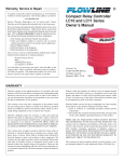
Warranty, Service & Repair
If for some reason your product must be returned for factory service, contact Dwyer Inc. at (219)879-8000 to receive a Material
Return Authorization number (MRA), providing the following
information:
1. Part Number, Serial Number
2. Name and telephone number of someone who can answer
technical questions related to the product and its application.
3. Return Shipping Address
4. Brief Description of the Symptom
5. Brief Description of the Application
Once you have received a Material Return Authorization number,
ship the product prepaid in its original packing to:
Thermal Dispersion
Flow Switch
TDS Series
Owner’s Manual
Dwyer Instruments Inc.
PO Box 373
102 Indiana Hwy, 212
Michigan City, IN 46361
Please include the information about the malfunction with your
product. This information enables our service technicians to
process your repair order as quickly as possible.
IP
68
Version 2.0.1A
All rights reserved
WARRANTY
Step One
About this Manual:
Material Compatibility:
PLEASE READ THE ENTIRE MANUAL PRIOR TO
INSTALLING OR USING THIS PRODUCT. This manual
includes information on all models of Dwyer Thermal Dispersion
Flow Switches: TDS series. Please refer to the part number located on the switch label to verify the exact model which you have
purchased.
The TDS series sensors are available in two different wetted materials.
Models TDS 1__ are made of Polypropylene (PP) with Ryton tips.
Models TDS 2__ are made of Polyvinylidene Fluoride (PVDF). Make
sure that the model you have selected is compatible with the application
liquid. To determine the chemical compatibility between the sensor and
its application liquids, refer to an industry reference such as the
Compass Corrosion Guide (available from Compass Publications,
phone 858-589-9636).
User’s Responsibility for Safety:
Dwyer manufactures a wide range of flow switches and technologies. While each of these sensors is designed to operate in a wide
variety of applications, it is the user’s responsibility to select a sensor model that is appropriate for the application, install it properly,
perform tests of the installed system, and maintain all components.
The failure to do so could result in property damage or serious
injury.
Proper Installation and Handling:
Because this is an electrically operated device, only properlytrained staff should install and/or repair this product. Use a proper
sealant with all installations. Never overtighten the sensor within
the fitting, beyond a maximum of 80 inch-pounds torque. Always
check for leaks prior to system start-up.
Wiring and Electrical:
The supply voltage used to power the sensor should never exceed a
maximum of 36 volts DC. Electrical wiring of the sensor should be
performed in accordance with all applicable national, state, and
local codes.
Flammable, Explosive and Hazardous Applications:
DO NOT USE THE TDS SERIES GENERAL PURPOSE FLOW
SWITCHES IN HAZARDOUS LOCATIONS.
WARNING
The rating for the relay is 120 VAC/60 VDC @ 1A. For CE
rated applications, the relay rating is 60 VAC/60 VDC @ 1A.
Dwyer’s Thermal Dispersion flow switches are not recommended for use with electrically charged application liquids.
For most reliable operation, the liquid being measured may
need to be electrically grounded.
SPECIFICATIONS
Step Two
Thermal Dispersion Ultrasonic Level Switch, LU10 Series
Electronics temp.:
Pressure:
Sensor rating:
Sensor material:
Cable jacket mat.:
Cable type:
Cable length:
Process mount:
Classification:
CE compliance:
0.7"
8’ Cable (2.5m)
2.1" (54mm)
2.8" (71mm)
4.5" (114mm)
3/4" NPT
3/4" NPT
0.7"
Contact output:
Process temp.:
3/4" NPT
(19mm)
Factory set point:
Repeatability:
Response time:
Set point adjust.:
Viscosity range:
Supply voltage:
Consumption:
Contact type:
Contact rating:
3/4" NPT
.04 to 3 fps
(.012 to .91 mps)
.2 fps (.06 mps)
± .5% of set point
1-10 seconds
Potentiometer
1-200 centipoise
12-36 VDC
70 mA maximum
(1) SPST relay
120 VAC/VDC @ 1A
(CE: 60 VAC/VDC @ 1A)
Selectable NO/NC
F: 32˚ to 140˚
C: 0˚ to 60˚
F: -40˚ to 140˚
C: -40˚ to 60˚
150 psi (10 bar) @ 25˚
C., derated @ 1.667
psi (.113 bar) per ˚C.
above 25˚ C.
NEMA 4X (IP65)
TDS1: PP-Ryton®
TDS2: PVDF Kynar®
TDS1: PP
TDS2: PFA Teflon®
4-conductor, #22 AWG
(shielded)
10' (3m)
3/4" NPT
General purpose
EN 50082-2 immunity
EN 55011 emission
EN 61010-1 safety
8’ Cable (2.5m)
0.7"
(19mm)
1.3" (32mm)
3.0" (76mm)
* all dimensions are Nominal
Set Points:
The TDS liquid flow switch set point is factory calibrated to 0.2
fps. To convert feet/sec to GPM, please refer to the chart
below.
TDS Series Volume vs Velocity
12" 10" 8"
1000
Flow Rate (gpm)
Set point range:
(19mm)
Common Specifications:
6"
4"
3"
2"
1-1/2"
1"
3/4"
1/2"
100
10
1
0.1
0.01
.01
.04
.1
TDS Series Flow Switch
.2
Velocity (fps)
1
3
10
TDS _ _ 2
Sensor Material
1 - PP
2 - PVDF
Sensor Length
1 - Short
2 - Long
Maximum Temperature/Voltage
Derating @ Maximum Current
150
Unacceptable
Range
125
100
075
050
Acceptable
Range
025
000
00
20
40
60
Temperature (C¡)
PVDF
80
PP
100
Electrical Loading Limits
100
80
Unacceptable
Range
60
40
20
00
12
Acceptable
Range
18
24
30
Operating Voltage (VDC)
36
Max. Series Resistance (Ohms)
175
Ambient Sensor Temperature (C¡)
Operating Pressure (psi)
Temperature/Pressure Derating
1,400
1,200
1,000
800
600
400
Unacceptable
Range
Acceptable
Range
200
0
12
18
24
30
Supply Voltage (VDC)
36
INTRODUCTION
INSTALLATION
Step Three
Step Four
Technology:
The TDS series flow switch when installed must always be in contact
with the liquid being measured. The flow switch feature a 3/4" NPT
threads which will allow it to be used with various types of fittings.
Be sure to check the insertion depth of the flow switch in the fitting
after it is installed. See the diagram below for the recommended insertion depth.
The thermal dispersion flow switch measures liquid temperature to
determine changes in flow velocity. As fluid flows across the sensing
tips, the temperature is reduced proportionately as a function of the
flow rate. When a temperature or velocity shift reaches the user
defined set point, the switch changes state indicating the appropriate
flow condition (flow or no-flow).
Dwyer's sophisticated electronics convert the temperature shift into a
signal which indicates whether a flow or no-flow condition occurs.
Depending on how the sensor is wired, this signal may be wired for
normally open or normally closed circuits.
Dwyer's Thermal Dispersion flow switches have no moving parts to
clog or foul, making them suitable for a variety of applications,
including non-coating and non-scaling liquids. The TDS series
directly measure mass flow and can operate over a broad range of liquids from 0.4 to 1.2 specific gravity, 1 to 200 cp.
Initialization Sequence for TDS series:
Powering up the TDS series is different in water and in air. When the
flow switch is powered up while submersed, the TDS series will
immediately indicate flow before switching to its correct state. When
the flow switch is powered up while in air, the TDS series will immediately indicate no-flow before indicating its correct state. A time
delay may be used to eliminate this initialization sequence. Dwyer's
thermal dispersion relay controllers feature a 0 to 60 second time
delay for your convenience.
le e
tab ng
ep n Ra
c
Ac rtio
e
Ins
in.
Dm
1/8
I
ipe
P
D
eI
Pip
When using any type of fitting, the orientation as well as the insertion
depth of the flow switch in the pipe is critical. See the diagram below
for the recommended orientation depth.
WARNING
The flow switch tips have a thin plastic wall which may be damaged if dropped or installed improperly.
The TDS series flow switch is designed for use in liquid. For best
results, avoid installing the TDS series where bubbles are present
or where the tips of the switch may be out of the liquid.
WIRING
WIRING
Step Five
Step Six
Supply Voltage:
The supply voltage to the TDS series flow switch should never exceed
a maximum of 36 VDC. Use controllers or power supplies, with a
minimum output of 12 VDC or a maximum output of 36 VDC.
Wiring the Relay Output:
Required Cable Length:
Determine the length of cable required between the TDS series flow
switch and its point of termination. Allow enough slack to ensure the
easy installation, removal and/or maintenance of the sensor. The
cable length may be extended up to a maximum of 1000 feet, using a
well-insulated, 14 to 20 gauge shielded four conductor cable.
Wire Stripping:
Using a 10 gauge wire stripper, carefully remove the outer layer of
insulation from the last 1-1/4" of the sensor's cable. Unwrap and discard the exposed foil shield from around the signal wires, leaving the
drain wire attached if desired. With a 20 gauge wire stripper, remove
the last 1/4" of the colored insulation from the signal wires.
Signal Output (Relay switching):
Allows the sensor to switch a small load on or off directly, using an
internal 1A relay [120 VAC/VDC or (CE: 60 VAC/VDC)]. The
NO/NC status is set by the polarity of the voltage feeding the red and
black wires. The green wire is the common for the relay and the white
wire is the NO or NC, depending on the polarity of red and black.
Normally Open Wiring:
Red
+
24 VDC
Power
Supply
-
Black
Shield
Ground
White
-
Green
+
Multimeter
(Continuity)
Wiring to a Dwyer Controller:
AC
(S)
(-)
GND
NC
R
C
115 VAC
220 VAC
NO
DELAY
(+)
Red
Black
Green
White
Shield - Not Used
AC
P
INVERT +/-
IN
PU
T
1
TSP Series Controller
The TDS series relay output can be wired as a dry contact to a VDC
or VAC power source. The TDS series does require 12 - 36 VDC
power to operate the sensor and switch the relay. All illustrations
below identify a Dry switch state as the normal position of the relay.
Switching a Normally Open DC Load:
The Red wire connects to Positive (+) of the power supply and the
Black wire connects to Negative (-). The LOAD can be attached to
either the Green or White wires. Complete the circuit by either connecting the Green to (+) VDC power or White to (-) VDC power (see
illustration below).
[Flow Condition]
Sensor
(NO)
INVERT
DELAY INVERT
-- +
DELAY
-- +
RELAY 1
RELAY 2
INPUT2A
White
Black
Green
Red
Not Used - Shield
ONOFF
OR
LOAD
[-]
[Flow Condition]
Sensor
(NC)
BLK
GRN
SHLD
WHT
RED
[+]
LOAD
OR
LOAD
[-]
Switching a Normally Open AC Load:
The Red wire connects to Positive (+) of the DC power supply and the
Black wire connects to Negative (-). The LOAD can be attached to
the Green wire and the Hot of the VAC power. Connect the White to
the Neutral of the VAC power (see illustration below).
[Flow Condition]
Sensor
(NO)
RED
GRN
SHLD
WHT
BLK
[+]
LOAD
[AC Power]
[-]
Switching a Normally Closed AC Load:
The Black wire connects to Positive (+) of the DC power supply and
the Red wire connects to Negative (-). The LOAD can be attached to
the Green wire and the Hot of the VAC power. Connect the White to
the Neutral of the VAC power (see illustration below).
[Flow Condition]
LATCH
INPUT1
[+]
LOAD
Switching a Normally Closed DC Load:
The Black wire connects to Positive (+) of the power supply and the
Red wire connects to Negative (-). The LOAD can be attached to
either the Green or White wires. Complete the circuit by either connecting the Green to (+) VDC power or White to (-) VDC power (see
illustration below).
TDC Series Controller
POWER
RED
GRN
SHLD
WHT
BLK
INPUT2B
Sensor
(NC)
BLK
GRN
SHLD
WHT
RED
[+]
LOAD
[AC Power]
[-]
WIRING
CALIBRATION
Step Seven
Step Eight
Wiring as a P-Channel or N-Channel output:
Set Points:
The TDS series relay output can be substituted for either a P-Channel
(PNP, sourcing) output or a N-Channel (NPN, sinking) output.
If the preset factory calibration is not adequate for your application,
follow the calibration steps listed below. Note: the switch's internal
LED will be on when the switch detects no-flow and will off when the
switch detects flow.
Normally Open DC Load as a P-Channel Output:
To wire as a NO P-Channel output, follow the directions below. The
Red wire connects to Positive (+) of the power supply and the Black
wire connects to Negative (-). The Green wire is jumpered to the Red
wire while the White wire is connected to the LOAD. Jumper the
LOAD back to the Negative (-) to complete the circuit.
[Flow Condition]
Sensor
(NO)
RED
GRN
SHLD
WHT
BLK
[+]
LOAD
[-]
Normally Closed DC Load as a P-Channel Output:
To wire as a NC P-Channel output, follow the directions below. The
Black wire connects to Positive (+) of the power supply and the Red
wire connects to Negative (-). The Green wire is jumpered to the
Black wire while the White wire is connected to the LOAD. Jumper
the LOAD back to the Negative (-) to complete the circuit.
[Flow Condition]
Sensor
(NC)
BLK
GRN
SHLD
WHT
RED
[+]
LOAD
[-]
Normally Open DC Load as a N-Channel Output:
To wire as a NO N-Channel output, follow the directions below. The
Red wire connects to Positive (+) of the power supply and the Black
wire connects to Negative (-). The White wire is jumpered to the
Black wire while the Green wire is connected to the LOAD. Jumper
the LOAD back to the Positive (+) to complete the circuit.
[Flow Condition]
Sensor
(NO)
2. Locate the potentiometer knob at the top
of the flow switch. The red LED is visible
through the potentiometer. (If the LED is
on, slowly adjust the potentiometer counterclockwise, with a small flat head
screwdriver until the LED turns off.) The
adjustment is a single turn 270° potentiometer. The initial response time of the
flow switch after adjustment is 1 to 10
seconds. Adjust the potentiometer in slow
increments and wait for the response.
[+]
LOAD
[-]
[Flow Condition]
BLK
GRN
SHLD
WHT
RED
[+]
LOAD
[-]
Potentiometer
Knob
If the LED is off, slowly adjust the potentiometer clockwise until the light turns on.
Then turn the potentiometer counterclockwise to bring the LED off at a reliable setting. Remember, adjust the potentiometer in slow increments and
wait for the response.
3. Verify that the new calibration is correct by lowering the system
flow rate below the set point and check to see that the red LED
turns on. Then increase the flow rate above the set point and verify that the red LED turns off accordingly.
TDS Series
0.2 fps
.04 fps
RED
GRN
SHLD
WHT
BLK
Normally Closed DC Load as a N-Channel Output:
To wire as a NC N-Channel output, follow the directions below. The
Black wire connects to Positive (+) of the power supply and the Red
wire connects to Negative (-). The White wire is jumpered to the Red
wire while the White wire is connected to the LOAD. Jumper the
LOAD back to the Positive (+) to complete the circuit.
Sensor
(NC)
1. Install the fitting and flow switch as described in the Installation
section of this manual. Turn the flow switch and controller power
on and adjust the flow rate to the application setting. If the medium to be sensed is likely to be subject to high temperature variations, the flow switch should be set at the highest normal temperature likely to be encountered.
3 fps
MAINTENANCE
Step Nine
Step Ten
General:
The TDS series flow switch requires no periodic maintenance except
to clean off any deposits or scaling from the sensor tip as necessary.
It is the responsibility of the user to determine the appropriate maintenance schedule, based on the specific characteristics of the application liquids.
Cleaning Procedure:
1. Power: Make Sure that all power to the sensor, controller and/or
power supply is completely disconnected.
2. Sensor Removal: Make sure that the flow is off and the pressure is down prior to removing the TDS series flow switch.
Carefully, remove the sensor from the installation. Replace the
sensor with a 3/4” NPT plug to insure that liquid does not leak out
during this procedure. Do not re-install the flow switch if the
threads are damaged.
3. Cleaning the Sensor: Use a soft bristle brush and mild detergent, carefully wash the TDS series flow switch. Do not use harsh
abrasives such as steel wool or sandpaper, which might damage
the surface sensor. Do not use incompatible solvents which may
damage the sensor's PP/Ryton or PVDF plastic body.
4. Sensor Installation: Follow the appropriate steps of installation as outlined in the installation section of this manual.
Testing the installation:
1. Power: Turn on power to the controller and/or power supply.
2. Immersing the switch: Immerse the sensing tip in its application liquid, by filling the tank up to the switches point of actuation. An alternate method of immersing the switch during preliminary testing is to hold a cup filled with application liquid up to
the switch's tip.
3. Test: With the switch being fluctuated between wet and dry
states, the switch indicator light in the controller should turn on
and off. If the controller doesn't have an input indicator, use a voltmeter or ammeter to ensure that the switch produces the correct
signal.
4. Point of actuation: Observe the point at which the rising or
falling fluid level causes the switch to change state, and adjust the
installation of the switch if necessary.
This
Space
Left
Intentionally
Blank