1
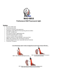
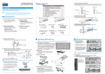
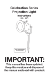
980, 990 & 997 Series Cord Reels
Service Manual
Daniel Woodhead Company
A Woodhead Industries, Inc. Subsidiary
Important Safety Instructions
Please read this manual carefully and follow its instructions. Improper use or failure to follow these instructions could
result in serious injury, death or property damage. Operators should be instructed in the safe and proper use and
maintenance of this product. Keep this manual for future reference.
The following safety precautions call attention to potentially dangerous conditions.
DANGER:
Immediate hazards which WILL result in severe personal injury or death.
WARNING:
Hazards or unsafe practices which COULD result in severe personal injury or death.
CAUTION:
Hazards or unsafe practices, which MAY result in, minor personal injury or product or
property damage.
INSTALLATION
CAUTION:
Operators should be instructed in the safe and proper use and maintenance of this
product. Keep this manual for future references.
WARNING:
Improper use or failure to follow these instructions could result in serious injury, death or
property damage.
WARNING:
This equipment should only be installed, adjusted & serviced by a qualified electrician in
accordance with the National Electric Code and any applicable local codes
Mounting
Wall or ceiling mount so that shaft is horizontal. When wall mounting, ensure large end of keyholes are facing
down. Centerline of drum should be in-line and perpendicular to intended cable payout. Secure reel to mounting
surface using 3/8” hardware suitable for specific mounting surface or structure.
Secondary Safety Cable
DANGER:
Attach a secondary safety cable or chain to all reels mounted overhead to prevent reel
from falling. Immediate hazards WILL result in severe personal injury or death.
For all overhead mounting, attach a secured secondary safety cable to hole provided on stand.
Wiring
WARNING:
Do not disconnect green wire, green wire is grounded to frame on all models and cannot
be used as a power conductor. Hazards or unsafe practices COULD result in severe
personal injury or death.
All internal wiring is completed at factory.
Reels equipped with handle and guard are ready for installation.
Optional Automatic Switch
If specified, reels come with switch to turn on power when cable
is extended and ratchet lock engaged. See parts kits if switch
needs to be added. If switch is not wanted, remove it and
connect lead-in wires directly to brushes.
SM3114-10B
Page 1 of 4
©AMCO Nov-01
ADJUSTMENT
Ratchet Lock
All models are equipped with a ratchet lock system. If
ratchet is not desired, remove wire inlet housing by
removing (3) screws on face, disengage ratchet if
engaged by rotating drum, rotate cam counterclockwise
until stop (@9:00 from base) and complete installation
screw at end of cam arm. Replace housing.
Cable Guide/Payout Orientation
The cable guide may be oriented in either of two positions –90 degrees apart. To change orientation, remove wire
inlet housing by removing (3) screws on face, remove two mounting screws completely from arm, loosen two
remaining mounting screws and rotate guide arm slowly to position. Reinstall two screws and tighten all four
screws. Replace housing.
Spring Tension
CAUTION:
Failure to test for adequate spring revolutions can cause spring damage. Hazards or
unsafe practices MAY result in minor personal injury or product or property damage.
Adjust tension before or after installation of reel. Increase tension by pulling out cord one revolution and, while
holding drum, pulling cord back through guide & wrapping around drum. To decrease tension, reverse procedure.
NOTE: Reel should have at least 2-3 initial “pre-turns” of tension and should complete the payout cycle with at
least one turn remaining to ensure normal operational life.
SERVICE
WARNING:
Disconnect ALL electrical power before dismantling any part of reel. Remove all spring
tension before attempting any service. Hazards or unsafe practices COULD result in
severe personal injury or death.
Power Spring Replacement
WARNING:
Do not remove spring cover from housing. Hazards or unsafe practices COULD result in
severe personal injury or death.
Disconnect reel from line. Remove all spring tension. Remove spring housing assembly by removing (3) screws
from front & pulling housing straight off drum assembly. Install new assembly by reversing steps.
NOTE: Internal hex of spring hub must line up with hex shaft to complete installation and must be installed
in proper direction to engage spring hook.
Working Cord Replacement
Disconnect reel from line. Remove all spring tension. Remove spring housing assembly by removing (3) screws
from front & pulling housing straight off drum assembly. Payout all cord from drum. Remove ball stop system from
cord. Remove cord from drum by disconnecting (3) conductors from ring terminals on inside of drum. Grip
connectors & pull straight out while holding ring terminals with needle nose pliers. Do not pull wires. Install new
working cord by reversing steps.
Lead-in Cord Replacement
Disconnect reel from line. Remove wire inlet housing by removing (3) screws from front. Remove strain relief
bracket from terminal block. Remove lead-in cord by disconnecting (3) conductors from brush terminals. Grip
connectors & pull straight out while holding brush terminals with needle nose pliers. Do not pull wires. Install new
lead-in cord by reversing steps.
Brush Replacement
Disconnect reel from line. Remove wire inlet housing by removing (3) screws from front. Disconnect lead-in cord
by removing (3) conductors from brush terminals. Grip connectors & pull straight out while holding brush
terminals with needle nose pliers. Do not pull wires. Remove brushes by removing screw from terminal & pulling
brush straight out. Install new brushes by reversing steps.
SM3114-10B
Page 2 of 4
©AMCO Nov-01
Ratchet Kit Replacement
Cam -Disconnect reel from line. Remove wire inlet
housing by removing (3) screws from front. Remove
screw & washer in center of cam; loosen screw on
support bracket and rotate bracket off pivot pin. Install
cam by reversing steps. Note: To ensure proper
interface with ratchet, cam finger must be positioned
between two 90deg apart ratchet fingers as per
picture. Install lock washer, screw, and tighten. After
reinstallation of new ratchet & cam system, test for
proper operation.
Ratchet & Spring. - Disconnect reel from line. Release
all spring tension. Remove spring housing assembly by
removing (3) screws, pull housing straight off drum
assembly. Remove retainer ring on shaft, removing
plastic bearing and slide drum off shaft. Remove screw
and washer holding ratchet and ratchet spring. Reverse
steps to install new ratchet. Spring legs should be
positioned between two “outer fingers” of cam & installed
between two stops (one plastic, one steel) on guide
arm/base assembly). Install screws and washers. It is
likely that cam will need repositioning. Remove 3 screws
from inlet housing and check position of Cam as per
above instruction.
REPLACEMENT PARTS
SM3114-10B
Page 3 of 4
©AMCO Nov-01
Ref
Qty
1
2
3
4
5
6
7
8
9
10
12
13
14
15
6
1
1
1
1
1
2
1
2
1
20
1
1
3
16
17
18
19
20
21
22
23
26
27
28
29
30
1
2
1
1
2
1
1
1
1
1
2
1
1
SM3114-10B
Part No. or Kit
E
E
E
E
E
E
A
A
A
A
AM10720109
AH88000001
AM10720110
AM10720111
AM10720115
AM10720117
C
C
C
C
A
A
A
D
Description
Ref
Qty
Part No. or Kit
Description
Screw; M4 x 30mm, PHMS
Housing; spring
Spring; main
Plate; spring seat
Plate; spring cover
Hub; spring
Retainer; E-ring, flat, 5/8” shaft
Flange; drum, outer
Bearing
Shaft; main
Screw; #8 x ½”, PH, thrd rolling
Flange; drum inner
Drum
Clamp; strain relief
Cord; 16/3 x51’, SJTOW
16/3 x 51’ w/ triplex outlet
14/3 x46’, SJTOW
12/3 x36’ SJTOW
16/4 x50’ SJTOW
14/4 x30’ SJTOW
Washer; 3/8” x 5/64”, flat
Yoke; mounting
Yoke
Pin; cotter, 3/32” x 1”
Ring; conductor, #1 (inner)
Ring, conductor, #2
Ring, conductor, #3 (outer)
Stand
Spring; ratchet pawl
Retainer; push-on, ¼” shaft
Guide; cord
Arm; guide
31
32
33
2
1
1
36
1
D
D
D
AM10720100
AM10720114
AM10720107
AM10720116
AM10720108
37
38
39
40
41
42
43
44
45
46
57
47+
4
1
1
1
*
*
0
3
1
1
2
1
Screw; M4 x 8mm, PHMS
Washer; #8 x 3/64” thick
Pawl; ratchet
Cord, grounded lead-in, 16/3
16/4
14/3
14/4
12/3
Screw; M5 x10mm, PHMS
Screw; M5 x 10mm, green
Block; terminal
Cam; ratchet pawl
Switch; miniature, 15A, 125V
Screw; #4 x 5/8” BHMS
Circuit Breaker; 250V,
Assy; brush
Seal; foam
Housing; wire inlet/hub
Washer; lock, M4
Ball Stop Parts + 48, 60,61
Page 4 of 4
D
F
F
B
D
G
Repair Part Kits
A
B
C
D
E
F
G
1
1
1
1
1
1
1
AH05040014
AH05040015
AH05040016
AH05040017
AH05040018
AH36220002
AH05010025
Drum Kit
Brush Kit
Swinging Mount Kit
Ratchet Lock Kit
Spring Kit
Automatic Switch Kit
Ball Stop Kit
©AMCO Nov-01