1
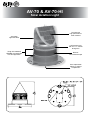
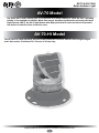
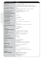
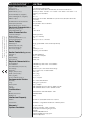
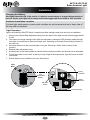
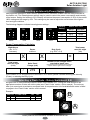
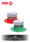
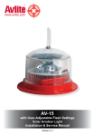
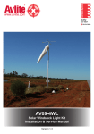
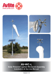
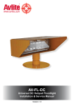
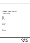
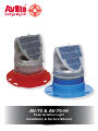
AV-70 & AV-70-HI
Solar Aviation Light
Installation & Service Manual
Version 5.0
AV-70 & AV-70-HI
Solar Aviation Light
Automatic
night activation
Dual internal
high-performance
solar modules
LED aviation lens
with 0 to +7° vertical
divergence
Tough UV-stabilised
LEXAN® polycarbonate
lens and light base
Band of
retro-reflective tape
User-replaceable
battery in sealed
compartment
AV-70 & AV-70-HI
Solar Aviation Light
Table of Contents
Introduction...........................................................................................Page 4
Operating Principle..............................................................................Page 4
Technology............................................................................................Page 4
AV-70 Model..........................................................................................Page 5
AV-70-HI Model......................................................................................Page 5
Installation.............................................................................................Page 8
Selecting an Intensity/Power Setting.................................................Page 9
Selecting a Flash Code........................................................................Page 9
Flash Codes........................................................................................Page 10
Installing the Light Assembly: Mounting Options...........................Page 15
Maintenance and Servicing...............................................................Page 19
Troubleshooting.................................................................................Page 20
Avlite Light Warranty..........................................................................Page 22
Version No.
3.2
4.0
4.1
5.0
Description
Update: AV-70-HI added
Update: Quality Logo
General Update
Update: Spec table & Code
Date
May 2010
May 2011
June 2012
January 2013
Approved
K. Paton
P. Rainey
J. Dore
J. Dore
Latest products and information available at www.avlite.com
3
AV-70 & AV-70-HI
Solar Aviation Light
Introduction
Congratulations! By choosing to purchase an Avlite light, you have become the
owner of one of the most advanced solar LED airfield lights in the world.
Avlite Systems draws on more than 25 years experience in the design and manufacture of navigation
aids, and particular care has been taken to ensure your light gives years of trouble free service.
As a commitment to producing the highest quality products for our customers, Avlite has been
independently certified as complying with the requirements of ISO 9001:2008 quality management
system.
By taking a few moments to browse through this booklet, you will become familiar with the versatility of
your light, and be able to maximise its operating function.
Please remember to complete the Avlite warranty registration card accompanying your light.
Operating Principle
The solar module of the light converts sunlight to an electrical current that is used to charge the
battery. The battery provides power to operate the light at night.
The flasher unit has very low current requirements. A microprocessor drives an array of ultra bright
LED’s through a DC/DC converter, which enables the LED’s to operate within the manufacturer’s
specifications. The battery is protected from over-charging within the circuit to ensure maximum
battery life.
On darkness, the microprocessor will initiate a program check and after approximately 1 minute will
turn on.
Technology
Avlite Systems is a world-class solar lighting systems manufacturer with a proven
reputation for rapid, innovative, and agile technology solutions designed specifically
for defense, government, civil and humanitarian aid operations in the most remote,
toughest environments.
Electronics
Avlite employs leading in-house electronic engineers in the design and development of software and
related circuitry. All individual electronic components are sourced directly by Avlite procurement staff
ensuring that only the highest quality components are used in our products.
LED Technology
All aviation lights use the latest advancements in LED (Light Emitting Diode) technology as a light
source. The major advantage of LED’s over traditional light sources is well established in that they
typically have an operational life in excess of 100,000 hours, resulting in substantial savings to
maintenance and servicing costs.
Precision Construction
Commitment to investing in the design and construction of injection-moulded parts including optic
lenses, light bases and a range of other components ensures that all Avlite products are of a
consistent and superior quality.
Optical Performance
Avlite manufactures a range of aviation LED lenses moulded from multi-cavity dies. Complex shapes
such as the AV-70 and 16-segment multi-focus lenses are a testament to the company’s superior inhouse lens manufacturing capabilities and outstanding optical performance.
Award-winning, Patented Technology
Several United States and Australian patent registrations are held on Avlite’s range of innovative
designs, with other regional patents pending in Canada, United Kingdom and Europe.
Latest products and information available at www.avlite.com
4
AV-70 & AV-70-HI
Solar Aviation Light
AV-70 Model
The Avlite AV-70 solar airfield light is exceptional in its unique ability to ‘track the sun’, operating
reliably in low sunlight conditions. Made from tough, durable polycarbonate and using the latest
high-intensity LED’s, the AV-70 light boasts dual high-performance solar modules incorporated
into Avlite’s world-first Solar Collection Lens.
AV-70-HI Model
The AV-70-HI is a high intensity version of the popular AV-70 and is ideal for use in high sunlight
areas that receive a minimum of 3.5 hours of sun per day.
Latest products and information available at www.avlite.com
5
SPECIFICATIONS•*
AV-70
Light Characteristics
Light Source
Available colors
Peak Intensity (cd)†
Horizontal Output (degrees)
Vertical Divergence (degrees)
Reflector Type
• Specifications subject to change or variation without notice
* Subject to standard terms and conditions
† Intensity setting subject to solar availability
Available Flash Characteristics
Intensity Adjustments
LED Life Expectancy (hours)
12 ultra-high intensity LEDs
Red, Green, White, Yellow, Amber, Blue, Sectored Combinations
Steady-on: Blue - 2.8 Red - 6.8 Green - 9.0 White - 7.0 Yellow - 6.5
Flashing: Blue - 5.5 Red - 18.2 Green - 21.9 White - 19.1 Yellow - 15.1
360
0 to +7
Omnidirectional 360° LED Reflector (US Pat. No. 6,667,582.
AU Pat. No. 778,918)
>250 including steady-on (user-adjustable)
Adjustable in 25% increments
>100,000
Electrical Characteristics
Operating Voltage (V)
Temperature Range
3.6
-40 to 80°C
Solar Characteristics
Solar Module Type
Output (watts)
Solar Module Efficiency (%)
Charging Regulation
Multicrystalline
2.5 (2 x 1.25watt)
14
Microprocessor controlled
Power Supply
Battery Type
Battery Capacity (Ah)
Nominal Voltage (V)
Autonomy (nights)
High grade NiMH – Environmentally friendly
8
3.6
Steady-on: >14
Flashing: >38 (14 hour darkness, 12.5% duty cycle)
Radio Controlled (optional)
Frequency
Range
Expandability
Compliance
2.4GHz ISM Band
Up to 1.4km relayed
AvMesh®
FCC / CE
Physical Characteristics
Body Material
Lens Material
Lens Diameter (mm/inches)
Lens Design
Mounting
Height (mm/inches)
Width (mm/inches)
Mass (kg/lbs)
Product Life Expectancy
LEXAN® Polycarbonate – UV stabilized
LEXAN® Polycarbonate – UV stabilized
140 / 5½
External optics with interior flute design
6 x 17mm holes on 200mm PCD
240 / 9½
231 / 91/8
1.1 / 23/8
Up to 12 years
Environmental Factors
Humidity
Icing
Wind Speed
Shock
Vibration
0 to 100%, MIL-STD-810F
22kg per square inch
Up to 160kph
MIL-STD-202G, Test Condition G, Method 213B
MIL-STD202G, Test Condition B, Method 204
Certifications
CE
Quality Assurance
Waterproof
EN61000-6-3:1997. EN61000-6-1:1997
ISO9001:2008
IP68
Intellectual Property
Patents
US Pat. No. 6,667,582. AU Pat. No. 778,918
Trademarks
AVLITE® is a registered trademark of Avlite Systems
Warranty *
Options Available
3 year warranty
• Radio Controlled – FCC compliant
• Avlite Pilot Activated Lighting Control
• IR LEDs
• External ON/OFF Switch
• External Battery Charging Port
• Manual Operation
SPECIFICATIONS•*
AV-70-HI
Light Characteristics
Light Source
Available colors
Peak Intensity (cd)†
Horizontal Output (degrees)
Vertical Divergence (degrees)
Reflector Type
Available Flash Characteristics
Intensity Adjustments
LED Life Expectancy (hours)
12 ultra-high intensity LEDs
Red, Green, White, Yellow, Amber, Blue, Sectored Combinations
Steady-on: Blue - 4.5 Red - 12.1 Green - 16.9 White - 14.2 Yellow - 11.6
Flashing: Not available
360
0 to +7
Omnidirectional 360° LED Reflector (US Pat. No. 6,667,582. AU Pat. No.
778,918)
Not available
Adjustable in 25% increments
>100,000
Electrical Characteristics
Operating Voltage (V)
Temperature Range
3.6
-40 to 80°C
Solar Characteristics
• Specifications subject to change or variation without notice
* Subject to standard terms and conditions
† Intensity setting subject to solar availability
Solar Module Type
Output (watts)
Solar Module Efficiency (%)
Charging Regulation
Multicrystalline
2.5 (2 x 1.25watt)
14
Microprocessor controlled
Power Supply
Battery Type
Battery Capacity (Ah)
Nominal Voltage (V)
Autonomy (nights)
High grade NiMH – Environmentally friendly
16
3.6
Steady-on: >19
Flashing: Not available
Radio Controlled (optional)
Frequency
Range
Expandability
Compliance
2.4GHz ISM Band
Up to 1.4km relayed
AvMesh®
FCC / CE
Physical Characteristics
Body Material
Lens Material
Lens Diameter (mm/inches)
Lens Design
Mounting
Height (mm/inches)
Width (mm/inches)
Mass (kg/lbs)
Product Life Expectancy
LEXAN® Polycarbonate – UV stabilized
LEXAN® Polycarbonate – UV stabilized
140 / 5½
External optics with interior flute design
6 x 17mm holes on 200mm PCD
240 / 9½
231 / 91/8
1.41 / 31/8
Up to 12 years
Environmental Factors
Humidity
Icing
Wind Speed
Shock
Vibration
0 to 100%, MIL-STD-810F
22kg per square inch
Up to 160kph
MIL-STD-202G, Test Condition G, Method 213B
MIL-STD202G, Test Condition B, Method 204
Certifications
CE
Quality Assurance
Waterproof
EN61000-6-3:1997. EN61000-6-1:1997
ISO9001:2008
IP68
Intellectual Property
Patents
US Pat. No. 6,667,582. AU Pat. No. 778,918
Trademarks
AVLITE® is a registered trademark of Avlite Systems
Warranty *
Options Available
3 year warranty
• Radio Controlled – FCC compliant
• Avlite Pilot Activated Lighting Control
• IR LEDs
• External ON/OFF Switch
• External Battery Charging Port
• Manual Operation
AV-70 & AV-70-HI
Solar Aviation Light
Installation
Charging the Battery
New lights should be left in the sun for 1-2 days to ensure battery is charged before placing in
service. Please note, light will re-charge even when toggle switch is turned to ‘OFF’ position.
Preferred Installation Location
For best light performance, ensure solar modules are not covered and are in clear view of
the sky with no shadows.
Light Operation
Light is activated by ON/OFF Switch. Intensity and flash settings need to be set prior to installation.
1. Remove the marked flash adjustment bung from the base of the light and set internal toggle switch
to ‘ON’.
2. The power and range settings of the light are adjusted by setting the DIP switches inside the light.
Your light is normally set to maximum range (see ‘Selecting an Intensity/Power Setting’ section of
this manual).
3. Set rotary switches to the required flash code (see ‘Selecting a Flash Code’ section of this
manual).
4. Replace flash adjustment bung.
5. A sealed vent on the base allows air transfer without moisture intake, and should not be disturbed.
6. To test place dark cover (towel or jacket) on top of light to activate sensor, light will come on within
one minute.
7. Ensure that the unit is bolted to an even, flat surface.
Light
Base
AD
456
23
2
456
23
F01
1
E
F01
ON
789A
BCD
T
ON / OFF
Switch
Rotary
Switch B
B
BCD
User
Replaceable
Battery
789A
E
JUS
ENT
A LE D
S
FLA H
M
SE
VENT
ON
A
Rotary
Switch A
Intensity Setting
Latest products and information available at www.avlite.com
8
AV-70 & AV-70-HI
Solar Aviation Light
Selecting an Intensity/Power Setting
Intensity/power settings on Avlite lanterns operate via DIP switches, located near the rotary switches on
the flasher unit. The intensity/power settings may be used to reduce the power consumption and intensity
of the lantern. Setting the lantern to 25% intensity will reduce the power consumption to 25% of the normal
100% setting and the range by 25%. This setting may be used to adjust the current draw of the light to
local sunlight conditions.
The following diagrams indicate intensity/power settings:-
ON
1
ON
2
1
100%
ON
2
1
75%
ON
2
1
50%
2
25%
Intensity
Setting
AV-70
Power: mA / hour
AV-70-HI
100%
34-36
54-56
75%
26-27
40-42
50%
17-18
27-28
25%
8-9
13-14
Power Consumption Calculator
Night Hours
(use 13.7 if
unknown)
Power
mA/hour
X
Total power
used per night
(mAh)
X
=
Number of full sunlight hours
required to break even
Solar Panel
Charge (mA)
/
Total power
used per night
(mA)
Duty Cycle
(e.g. 20% = 0.2)
279
(the amount of time it will take for the solar to
replace what the light took out overnight)
=
If the number of Full Sunlight hours is less than 2.5-3.0 hours, please consider reducing the intensity
(Power) or reducing the Duty Cycle.
Selecting a Flash Code - Rotary Switches A & B
All lights have 2 rotary switches marked A and B on the flasher unit. Turning the small arrows to the
appropriate number or letter will set the code (see ‘Flash Codes’ section, of this manual). The unit may
take up to one minute to activate a new flash code. A comprehensive list of available flash codes is listed
on pages in the ‘Flash Codes’ section of this manual.
2.7
B
23
789A
BCD
456
0.3
456
FL 3 S
23
OFF
E
F01
0
ON
F01
A
FLASH CODE
BCD
SWITCH
A
B
789A
E
Example:
Latest products and information available at www.avlite.com
9
A
AV-70 & AV-70-HI
Solar Aviation Light
Flash Codes
AVLITE® code reference is listed by number of flashes
For the latest version of this document visit www.avlite.com,
or email [email protected]
Symbols
FL
Flash followed by number Eg. FL 1 S, one flash every second
F
Fixed
Q
Quick flash
VQ
Very quick flash
OC
Occulting; greater period on than off
ISO
Isophase; equal period on and off
LFL Long flash long
MO
Morse code ( ) contains letter
For example, VQ (6) + LFL 10 S means 6 very quick flashes followed by a long flash, during a
10-second interval.
The amount of power your light draws through the night depends on the duty cycle, i.e. the amount of
time on as a proportion to the timing cycle. For example, 0.5 seconds on and 4.5 seconds off equals a
10% duty cycle.
It is best to operate at the lowest duty cycle appropriate to the actual needs of the application.
Please note, Avlite models will retain full autonomy in normal operating conditions with duty-cycles up to
approximately 30%. In applications whereby duty cycles exceed this limit, a reduction in light intensity is
recommended. Please contact a Avlite consultant if assistance is required.
Latest products and information available at www.avlite.com
10
SWITCH
A
B
0
D
E
F
7
8
9
A
8
B
9
C
F
1
0
0
2
3
4
5
6
7
1
8
9
D
1
A
2
B
3
C
D
2
5
E
4
4
5
E
F
6
0
1
2
3
3
F
3
8
4
5
9
6
0
3
3
3
3
3
3
3
4
3
4
3
4
0
5
4
0
0
0
0
0
0
2
0
0
6
5
0
5
0
5
0
0
2
4
2
6
5
5
0
0
5
1
1
1
2
6
2
1
5
1
1
5
1
FLASH CODE
ON
OFF
F (Steady light)
VQ 0.5 S
VQ 0.6 S
VQ 0.6 S
Q1S
Q1S
Q1S
Q1S
Q1S
Q 1.2 S
Q 1.2 S
Q 1.2 S
FL 1.5 S
FL 1.5 S
FL 1.5 S
FL 1.5 S
FL 2 S
FL 2 S
FL 2 S
FL 2 S
FL 2 S
FL 2 S
ISO 2 S
FL 2.5 S
FL 2.5 S
FL 2.5 S
FL 3 S
FL 3 S
FL 3 S
FL 3 S
FL 3 S
FL 3 S
FL 3 S
ISO 3 S
OC 3 S
OC 3 S
OC 3.5 S
FL 4 S
FL 4 S
FL 4 S
FL 4 S
FL 4 S
FL 4 S
FL 4 S
FL 4 S
ISO 4 S
OC 4 S
OC 4 S
FL 4.3 S
FL 5 S
FL 5 S
FL 5 S
FL 5 S
FL 5 S
0.2
0.2
0.3
0.2
0.3
0.4
0.5
0.8
0.3
0.5
0.6
0.2
0.3
0.4
0.5
0.2
0.3
0.4
0.5
0.7
0.8
1.0
0.3
0.5
1.0
0.2
0.3
0.4
0.5
0.6
0.7
1.0
1.5
2.0
2.5
2.5
0.2
0.3
0.4
0.5
0.6
0.8
1.0
1.5
2.0
2.5
3.0
1.3
0.2
0.3
0.5
0.9
1.0
0.3
0.4
0.3
0.8
0.7
0.6
0.5
0.2
0.9
0.7
0.6
1.3
1.2
1.1
1.0
1.8
1.7
1.6
1.5
1.3
1.2
1.0
2.2
2.0
1.5
2.8
2.7
2.6
2.5
2.4
2.3
2.0
1.5
1.0
0.5
1.0
3.8
3.7
3.6
3.5
3.4
3.2
3.0
2.5
2.0
1.5
1.0
3.0
4.8
4.7
4.5
4.1
4.0
SWITCH
A
B
7
4
8
0
1
2
C
B
C
8
9
A
7
B
5
9
6
3
4
A
9
5
D
C
E
B
6
A
6
B
F
C
7
0
1
D
2
E
1
C
D
7
2
8
5
6
F
D
3
0
4
7
A
E
1
2
2
3
3
3
6
5
5
1
1
1
5
1
2
2
4
3
3
4
6
6
5
1
5
4
2
2
6
2
5
4
6
6
6
1
6
1
4
2
2
2
4
6
3
3
1
4
4
2
4
4
6
4
FLASH CODE
ON
OFF
FL 5 S
ISO 5 S
LFL 5 S
OC 5 S
OC 5 S
OC 5 S
FL 6 S
FL 6 S
FL 6 S
FL 6 S
FL 6 S
FL 6 S
FL 6 S
FL 6 S
ISO 6 S
LFL 6 S
OC 6 S
OC 6 S
OC 6 S
FL 7 S
FL 7 S
OC 7 S
FL 7.5 S
FL 7.5 S
FL 8 S
FL 8 S
ISO 8 S
LFL 8 S
OC 8 S
LFL 8 S
FL 9 S
FL 9 S
OC 9 S
FL 10 S
FL 10 S
FL 10 S
FL 10 S
FL 10 S
FL 10 S
LFL 10 S
LFL 10 S
ISO 10 S
LFL 10 S
OC 10 S
OC 10 S
OC 10 S
FL 12 S
FL 12 S
LFL 12 S
FL 15 S
LFL 15 S
OC 15 S
LFL 20 S
FL 26 S
1.5
2.5
2.0
3.0
4.0
4.5
0.2
0.3
0.4
0.5
0.6
1.0
1.2
1.5
3.0
2.0
4.0
4.5
5.0
1.0
2.0
4.5
0.5
0.8
0.5
1.0
4.0
2.0
5.0
3.0
0.9
1.0
6.0
0.2
0.3
0.5
0.8
1.0
1.5
2.0
3.0
5.0
4.0
6.0
7.0
7.5
1.2
2.5
2.0
1.0
4.0
10
2.0
1.0
3.5
2.5
3.0
2.0
1.0
0.5
5.8
5.7
5.6
5.5
5.4
5.0
4.8
4.5
3.0
4.0
2.0
1.5
1.0
6.0
5.0
2.5
7.0
6.7
7.5
7.0
4.0
6.0
3.0
5.0
8.1
8.0
3.0
9.8
9.7
9.5
9.2
9.0
8.5
8.0
7.0
5.0
6.0
4.0
3.0
2.5
10.8
9.5
10.0
14.0
11.0
5.0
18.0
25.0
Latest products and information available at www.avlite.com
11
AV-70 & AV-70-HI
Solar Aviation Light
SWITCH
A
B
0
A
E
B
1
A
2
A
3
A
F
9
2
C
4
A
0
7
1
7
9
B
2
9
5
A
7
8
A
A
6
A
7
A
9
9
2
8
3
7
3
9
A
9
7
B
8
A
4
7
8
8
5
7
4
C
5
C
F
B
9
A
6
7
7
7
6
9
8
7
B
9
9
7
4
9
B
A
C
9
D
9
A
8
A
7
8
B
C
A
D
A
FLASH CODE
ON
OFF
ON
OFF
FL (2) 4 S
VQ (2) 4 S
FL (2) 4.5 S
FL (2) 4.5 S
FL (2) 4.5 S
FL (2) 5 S
FL (2) 5 S
FL (2) 5 S
FL (2) 5 S
FL (2) 5 S
Q (2) 5 S
Q (2) 5 S
FL (2) 5.5 S
FL (2) 6 S
FL (2) 6 S
FL (2) 6 S
FL (2) 6 S
FL (2) 6 S
FL (2) 6 S
FL (2) 6 S
Q (2) 6 S
FL (2) 7 S
FL (2) 8 S
FL (2) 8 S
FL (2) 8 S
FL (2) 8 S
FL (2) 8 S
OC (2) 8 S
OC (2) 8 S
VQ (2) 8 S
FL (2) 10 S
FL (2) 10 S
FL (2) 10 S
FL (2) 10 S
FL (2) 10 S
FL (2) 10 S
FL (2) 10 S
Q (2) 10 S
FL (2) 12 S
FL (2) 12 S
FL (2) 12 S
FL (2) 15 S
FL (2) 15 S
Q (2) 15 S
FL (2) 20 S
FL (2) 25 S
0.5
0.2
0.3
0.4
0.5
0.2
0.2
0.4
0.5
1.0
0.3
0.5
0.4
0.3
0.3
0.3
0.4
0.5
0.8
1.0
0.3
1.0
0.4
0.4
0.5
0.8
1.0
3.0
5.0
0.2
0.4
0.5
0.5
0.5
0.8
1.0
1.0
0.6
0.4
0.5
1.5
0.5
1.0
0.2
1.0
1.0
1.0
1.0
1.0
1.0
1.0
0.8
1.2
0.6
1.0
1.0
0.7
0.5
1.4
0.6
0.9
1.0
1.0
1.0
1.2
1.0
0.7
1.0
0.6
1.0
1.0
1.2
1.0
2.0
1.0
1.0
1.6
1.0
1.5
2.0
1.2
1.0
1.5
0.4
1.0
1.0
2.0
1.5
2.0
0.8
3.0
1.0
0.5
0.2
0.3
0.4
0.5
0.2
0.2
0.4
0.5
1.0
0.3
0.5
0.4
1.0
0.3
0.3
0.4
0.5
0.8
1.0
0.3
1.0
2.0
0.4
0.5
2.4
1.0
1.0
1.0
0.2
0.4
0.5
0.5
0.5
0.8
1.0
1.0
0.6
0.4
0.5
1.5
2.0
1.0
0.2
1.0
1.0
2.0
2.6
2.9
2.7
2.5
3.8
3.4
3.6
3.0
2.0
3.7
3.5
3.3
4.1
4.5
4.4
4.2
4.0
3.2
3.0
4.7
4.0
5.0
6.2
6.0
3.6
5.0
2.0
1.0
6.6
7.6
8.0
7.5
7.0
7.2
7.0
6.5
8.4
10.2
10.0
7.0
11.0
11.0
13.8
15.0
22.0
SWITCH
A
B
7
9
5
9
0
C
E
9
3
C
2
B
FLASH CODE
ON
OFF
ON
OFF
ON
OFF
Q (3) 5 S
VQ (3) 5 S
VQ (3) 5 S
VQ (3) 5 S
FL (3) 6 S
FL (2+1) 6 S
0.5
0.2
0.3
0.3
0.5
0.3
0.5
0.3
0.2
0.3
1.0
0.4
0.5
0.2
0.3
0.3
0.5
0.3
0.5
0.3
0.2
0.3
1.0
1.2
0.5
0.2
0.3
0.3
0.5
0.3
2.5
3.8
3.7
3.5
2.5
3.5
Latest products and information available at www.avlite.com
12
AV-70 & AV-70-HI
Solar Aviation Light
SWITCH
A
B
A
B
F
A
0
B
B
7
B
8
C
8
C
B
C
7
D
B
D
7
3
8
8
9
B
B
D
8
1
B
E
A
E
7
B
6
4
8
5
8
1
8
F
7
9
D
0
8
F
8
0
9
1
9
6
8
1
C
4
B
3
B
5
B
6
B
SWITCH
A
B
B
F
B
D
8
D
1
D
2
D
F
E
B
E
4
F
C
E
3
D
A
D
4
D
8
E
7
D
D
E
C
D
5
D
0
D
3
F
0
F
E
E
6
F
FLASH CODE
ON
OFF
ON
OFF
ON
OFF
Q (3) 6 S
FL (3) 8 S
FL (3) 9 S
FL (3) 9 S
FL (3) 10 S
FL (3) 10 S
FL (3) 10 S
FL (3) 10 S
FL (3) 10 S
FL (3) 10 S
FL (2+1) 10 S
OC (3) 10 S
Q (3) 10 S
FL (2 + 1) 10 S
FL (3) 12 S
FL (3) 12 S
FL (3) 12 S
FL (3) 12 S
FL (2+1) 12 S
FL (2+1) 12 S
FL (2+1) 13.5 S
FL (3) 15 S
FL (3) 15 S
FL (3) 15 S
FL (2+1) 15 S
FL (2+1) 15 S
FL (2+1) 15 S
FL (2+1) 15 S
VQ (3) 15 S
FL (3) 20 S
FL (3) 20 S
FL (3) 20 S
FL (3) 20 S
0.3
0.5
0.3
0.8
0.3
0.4
0.5
0.5
0.6
1.0
0.5
5.0
0.3
0.5
0.5
0.5
0.8
1.0
0.8
1.0
1.0
0.3
0.4
0.5
0.6
0.7
0.7
1.0
0.1
0.5
0.5
0.8
1.0
0.7
1.0
1.0
1.2
0.7
0.6
0.5
1.5
0.6
1.0
0.7
1.0
0.7
0.5
1.5
2.0
1.2
1.0
1.2
1.0
1.0
1.7
1.0
1.5
0.3
0.5
0.7
2.0
0.5
3.0
1.5
1.2
1.0
0.3
0.5
0.3
0.8
0.3
0.4
0.5
0.5
0.6
1.0
0.5
1.0
0.3
0.5
0.5
0.5
0.8
1.0
0.8
1.0
1.0
0.3
0.4
0.5
0.6
0.7
0.7
1.0
0.1
0.5
0.5
0.8
1.0
0.7
1.0
1.0
1.2
0.7
0.6
0.5
1.5
0.6
1.0
2.1
1.0
0.7
0.5
1.5
2.0
1.2
3.0
2.4
4.0
4.0
1.7
1.0
1.5
0.3
0.5
0.7
5.0
0.5
3.0
1.5
1.2
1.0
0.3
0.5
0.3
0.8
0.9
1.2
0.5
0.5
0.6
1.0
0.5
1.0
0.3
1.5
0.5
0.5
0.8
1.0
0.8
1.0
1.0
0.3
0.4
0.5
1.4
1.9
2.1
1.0
0.1
0.5
0.5
0.8
1.0
3.7
4.5
6.1
4.2
7.1
6.8
7.5
5.5
7.0
5.0
5.7
1.0
7.7
6.5
7.5
6.5
7.2
5.0
6.0
4.0
5.5
10.7
11.8
10.5
11.8
10.7
10.1
5.0
13.7
12.5
15.5
15.2
15.0
FLASH CODE
ON
OFF
ON
OFF
ON
OFF
ON
OFF
VQ (4) 4 S
Q (4) 6 S
Q (4) 6 S
FL (4) 10 S
FL (4) 10 S
Q (4) 10 S
FL (4) 12 S
FL (4) 12 S
FL (4) 12 S
FL (4) 12 S
Q (4) 12 S
FL (4) 15 S
FL (4) 15 S
FL (4) 15 S
FL (4) 16 S
FL (4) 20 S
FL (4) 20 S
FL (4) 20 S
FL (4) 20 S
Q (4) 20 S
Q (4) 28 S
FL (4) 30 S
0.3
0.3
0.4
0.5
0.8
0.3
0.3
0.5
0.5
0.8
0.3
0.5
1.0
1.5
0.5
0.3
0.5
0.5
1.5
0.5
0.5
0.5
0.3
0.7
0.6
1.0
1.2
0.7
1.7
0.5
1.5
1.2
0.7
1.5
1.0
0.5
1.5
3.0
1.5
1.5
1.5
0.5
0.5
0.5
0.3
0.3
0.4
0.5
0.8
0.3
0.3
0.5
0.5
0.8
0.3
0.5
1.0
0.5
0.5
0.3
0.5
0.5
1.5
0.5
0.5
0.5
0.3
0.7
0.6
1.0
1.2
0.7
1.7
0.5
1.5
1.2
0.7
1.5
1.0
0.5
1.5
3.0
1.5
1.5
1.5
0.5
0.5
0.5
0.3
0.3
0.4
0.5
0.8
0.3
0.3
0.5
0.5
0.8
0.3
0.5
1.0
0.5
0.5
0.3
0.5
0.5
1.5
0.5
0.5
0.5
0.3
0.7
0.6
1.0
1.2
0.7
1.7
0.5
1.5
1.2
0.7
1.5
1.0
0.5
1.5
3.0
1.5
4.5
1.5
0.5
0.5
0.5
0.3
0.3
0.4
0.5
0.8
0.3
0.3
0.5
0.5
0.8
0.3
0.5
1.0
0.5
0.5
0.3
0.5
0.5
1.5
0.5
0.5
0.5
2.3
2.7
2.6
5.0
3.2
6.7
5.7
8.5
5.5
5.2
8.7
8.5
8.0
10.5
9.5
9.8
13.5
10.5
9.5
16.5
24.5
26.5
Latest products and information available at www.avlite.com
13
AV-70 & AV-70-HI
Solar Aviation Light
SWITCH
A
B
D
D
E
D
E
8
5
F
9
F
9
E
SWITCH
A
B
F
D
A
F
7
F
SWITCH
A
B
6
E
7
E
2
F
2
E
3
E
8
F
SWITCH
A
B
4
E
5
E
1
F
0
E
1
E
FLASH CODE
ON
OFF
ON
OFF
ON
OFF
ON
OFF
ON
OFF
Q (5) 7 S
Q (5) 10 S
FL (5) 12 S
FL (5) 20 S
FL (5) 20 S
FL (5) 20 S
0.3
0.3
0.5
0.5
0.8
1.0
0.7
0.7
1.5
0.5
1.2
1.0
0.3
0.3
0.5
0.5
0.8
1.0
0.7
0.7
1.5
0.5
1.2
1.0
0.3
0.3
0.5
0.5
0.8
1.0
0.7
0.7
1.5
0.5
1.2
1.0
0.3
0.3
0.5
0.5
0.8
1.0
0.7
0.7
1.5
0.5
1.2
1.0
0.3
0.3
0.5
0.5
0.8
1.0
2.7
5.7
3.5
15.5
11.2
11.0
FLASH CODE
ON
OFF
ON
OFF
ON
OFF
ON
OFF
ON
OFF
ON
OFF
Q (6) 10 S
FL (6) 15 S
FL (6) 15 S
0.3
0.3
0.5
0.7
0.7
1.0
0.3
0.3
0.5
0.7
0.7
1.0
0.3
0.3
0.5
0.7
0.7
1.0
0.3
0.3
0.5
0.7
0.7
1.0
0.3
0.3
0.5
0.7
0.7
1.0
0.3
0.3
0.5
4.7
9.7
7.0
FLASH CODE
ON
OFF
ON
OFF
ON
OFF
ON
OFF
ON
OFF
ON
OFF
ON
OFF
VQ (6) + LFL 10 S
VQ (6) + LFL 10 S
Q (6) + LFL 15 S
Q (6) + LFL 15 S
Q (6) + LFL 15 S
VQ (6) + LFL 15 S
0.2
0.3
0.2
0.3
0.6
0.3
0.3
0.3
0.8
0.7
0.6
0.3
0.2
0.3
0.2
0.3
0.6
0.3
0.3
0.3
0.8
0.7
0.6
0.3
0.2
0.3
0.2
0.3
0.6
0.3
0.3
0.3
0.8
0.7
0.6
0.3
0.2
0.3
0.2
0.3
0.6
0.3
0.3
0.3
0.8
0.7
0.6
0.3
0.2
0.3
0.2
0.3
0.6
0.3
0.3
0.3
0.8
0.7
0.6
0.3
0.2
0.3
0.2
0.3
0.6
0.3
0.3
0.3
0.8
0.7
0.6
0.3
2.0
2.0
2.0
2.0
2.0
2.0
5.0
4.4
7.0
7.0
5.8
9.4
FLASH CODE
ON
OFF
ON
OFF
ON
OFF
ON
OFF
ON
OFF
ON
OFF
ON
OFF
ON
OFF
ON
OFF
VQ (9) 10 S
VQ (9) 10 S
Q (9) 15 S
Q (9) 15 S
Q (9) 15 S
0.2
0.3
0.2
0.3
0.6
0.3
0.3
0.8
0.7
0.6
0.2
0.3
0.2
0.3
0.6
0.3
0.3
0.8
0.7
0.6
0.2
0.3
0.2
0.3
0.6
0.3
0.3
0.8
0.7
0.6
0.2
0.3
0.2
0.3
0.6
0.3
0.3
0.8
0.7
0.6
0.2
0.3
0.2
0.3
0.6
0.3
0.3
0.8
0.7
0.6
0.2
0.3
0.2
0.3
0.6
0.3
0.3
0.8
0.7
0.6
0.2
0.3
0.2
0.3
0.6
0.3
0.3
0.8
0.7
0.6
0.2
0.3
0.2
0.3
0.6
0.3
0.3
0.8
0.7
0.6
0.2
0.3
0.2
0.3
0.6
5.8
4.9
6.8
6.7
4.8
SWITCH FLASH CODE
ON OFF
A
B
MORSE CODE ( ) INDICATES LETTER
7
8
MO (A) 6 S
0.3
0.6
7
B
MO (A) 8 S
0.4
0.6
8
8
MO (A) 8 S
0.8
1.2
B
8
MO (U) 10 S
0.3
0.7
C
8
MO (U) 10 S
0.4
0.6
D
8
MO (U) 10 S
0.5
0.5
9
8
MO (A) 10 S
0.5
0.5
8
9
MO (D) 10 S
5.0
1.0
A
8
MO (A) 15 S
0.5
1.5
F
8
MO (U) 15 S
0.6
0.3
0
9
MO (U) 15 S
0.7
0.5
1
9
MO (U) 15 S
0.7
0.7
7
D
MO (B) 15 S
1.5
0.5
ON
OFF
1.0
2.0
2.4
0.3
0.4
0.5
1.5
1.0
2.0
0.6
0.7
0.7
0.5
4.1
5.0
3.6
0.7
0.6
0.5
7.5
1.0
11.0
0.3
0.5
0.7
0.5
ON
OFF
0.9
1.2
1.5
7.1
6.8
6.5
1.0
1.0
1.4
1.9
2.1
0.5
11.8
10.7
10.1
0.5
ON
OFF
0.5
10.5
Latest products and information available at www.avlite.com
14
AV-70 & AV-70-HI
Solar Aviation Light
Installing the Light Assembly: Mounting Options
Installing the Light Assembly to the Rubber Tile
The completed AV-70 rubber tile assembly is to be mounted on a surface capable of supporting 6kg
minimum. Securing the rubber tile to the mounting surface is optional, however, Avlite recommend that
the tile be secured at a minimum of two points.
a. Insert bolts through the three-centremost holes in the tile, entering from the bottom face (within the
triangular recess). It may be necessary to use a rubber mallet to insert the bolts.
b. Fit the AV-70 light over the bolts on the top face of the tile. (It is possible to align the lens ridge with
the sides of the tile, but this is not a requirement).
c. Install a penny washer and a Nylock nut on each bolt and tighten.
d. Place the completed light assembly in the desired location.
e. During Installation every effort should be made to ensure that the light is level when installation is
complete. When installing the tile ensure that it is level using a spirit level.
f. Using a hammer, drive steel pegs through the holes in the corners of the rubber tile being careful
not to damage the AV-70 light.
Note: Other means of securing the tile may be used where the mounting surface is not suited to the
use of steel pegs.
Latest products and information available at www.avlite.com
15
AV-70 & AV-70-HI
Solar Aviation Light
Figure 2 Rubber Tile Installation
5
4
1
6
2
3
Item
Description
Qty
1
AV-70 Solar Airfiled Light
1
2
Rubber Tile
1
3
Bolt, 8mm x 50
3
4
Penny Washer, 8mm
3
5
Nylock Nut, 8mm
6
Steel Peg, Ø12mm
3
Optional (2)
Latest products and information available at www.avlite.com
16
AV-70 & AV-70-HI
Solar Aviation Light
Installing the Light Assembly to the Frangible Stake Mount
The completed AV-70 mount plate assembly is to be mounted on the Stake (Fig 3) in firm soil (not
loose sand, screenings or other unbound material).
a. Fit the AV-70 light on the top of the mounting plate. Insert bolts through the four holes in the mount,
entering from the bottom. Install a penny washer and a Nylock nut on each bolt and tighten.
b. Fit the boss of the mount plate into the shorter barrel of the frangible sleeve. Using a 6mm Allen
key, tighten the socket head cap screw against the stake mount boss.
c. Use a sledge hammer to drive the stake into the soil at the chosen location. Drive the stake down
until the bottom of the stake sleeve is at ground level.
During Installation every effort should be made to ensure that the light is level when installation is
complete. When installing a stake mount into the ground ensure that the stake is installed straight
into the ground and not on an angle. Ensure that the mounting plate is level using a spirit level.
d. Fit the AV-70 mount plate assembly on top of the stake. The longer barrel of the Frangible Sleeve
should completely cover the stake sleeve. Using a 6mm Allen key, tighten the bottom socket head
cap screw against the stake sleeve.
7
6
Item
1
2
Qty
AV-70 Solar Airfiled Light
1
2
Mount Plate
1
3
Frangible Sleeve
1
4
Stake (355mm)
1
5
Bolt, 8mm x 30
4
6
Penny Washer, 8mm
4
7
Nylock Nut, 8mm
4
8
Socket Head Cap Screw,
8mm x 16
2
9
Allen Key, 6mm
1
Figure 3 Frangible Stake Mount Installation
5
3
Description
1
8
9
4
Latest products and information available at www.avlite.com
17
AV-70 & AV-70-HI
Solar Aviation Light
Installing the Light Assembly to the Frangible Concrete Mount
a. Mount the base plate to the concrete using 4 x M8 concrete bolts.
b. Fit the frangible mounting plate onto the concrete base plate and secure using the M8 x 16 SHCS
c. During Installation every effort should be made to ensure that the light is level when installation is
complete.
The following guide lines will help to ensure that the lights will be installed correctly.
- When installing a concrete mount plate ensure that the concrete pad is level using a spirit
level.
Check the mounting
plate with a spirit
level in all directions
- Fit the frangible coupling and top mounting plate and using a spirit level check that the light
mounting plate is level using a spirit level.
d. Fit the AV-70 to the light mounting plate using M8 SHCS, large flat washers and Nylock nuts.
Note: After adjustments, ensure all nuts and bolts are tightened securely and all tools, spares and
packaging are removed from the runway.
Item
Description
Qty
1
AV-70 Solar Airfiled Light
1
2
Mount Plate
2
3
Frangible Sleeve
1
4
Bolt, 8mm x 25
4
5
Penny Washer, 8mm
4
6
Nylock Nut, 8mm
4
7
Socket Head Cap Screw,
8mm x 16
2
8
Allen Key, 6mm
1
Figure 4 Frangible Concrete Mount
Installation
Latest products and information available at www.avlite.com
18
AV-70 & AV-70-HI
Solar Aviation Light
Maintenance and Servicing
Designed to be maintenance free, the AV-70 / AV-70-HI requires minimal attention, though the following
maintenance and servicing information is provided to help ensure the life of your Avlite product.
1. Cleaning Solar Panels - occasional cleaning of the solar panels may be required. Using a cloth and
warm soapy water, wipe off any foreign matter before rinsing the panels with fresh water.
2. Battery Check - inspection of batteries should be performed every three years (minimum) to ensure
that the charger, battery and ancillary electronics are functioning correctly. Using a voltage meter,
check that the battery voltage is at least 3.6 volts under 100mA load, and ensure all terminals are
clear of foreign matter.
Replacing the battery- Don’t throw the unit out!!
The AV-70 / AV-70-HI lights are the only compact aviation light with a double sealed battery
compartment. This provides the user with the ability to change the battery after years of operation.
1. Remove the marked flash adjustment bung from the base of the light and set internal toggle switch
to ‘OFF’.
2. Unscrew small screws to remove battery plate.
3. Remove battery from AV-70 / AV-70-HI case and unscrew positive and negative leads.
4. Discard old battery in a safe manner.
5. Reattach positive and negative leads to new battery and then place back into case.
6. Reattach battery plate and switch light ‘ON’ via internal switch. Close the bung.
7. To test place dark cover (towel or jacket) on top of light to activate sensor, light will come on.
Care must be taken to observe the polarity of the battery before the leads are re-connected, and
ensure the replacement battery is correctly fitted. Always discard old batteries in a safe manner.
Long Term Storage Instructions
If the AV-70 / AV-70-HI is to be placed in storage for an extended period, being more than 5 months,
please follow the below steps.
1.
2.
3.
4.
5.
6.
The 3.6V NiMH Battery must be stored in a fully charged condition.
Remove the Flash Adjustment plug and turn the ON/OFF switch to the OFF position.
Remove the battery cover and disconnect the Positive (+) Terminal.
Fold the Terminal away from the Negative Battery Terminal.
Replace the Battery Cover
Replace the Flash Adjustment Plug.
All batteries will discharge over time and the rate of discharge is dependent on temperature. If the light is
being stored in temperatures greater than 40°C the battery will discharge faster.
Please check battery every 3-6 months and recharge if necessary.
Recharging the Battery
1. Remove the Battery Cover and connect the Positive Terminal.
2. Remove the Flash Adjustment Plug and turn the ON/OFF switch to the ON position.
3. Reconnect the Light Head and place unit in the sun for 2-4 days
Or
Reconnect Light Head and place in front of a halogen lamp for 2-3 days. (Do not place the halogen light
too close to the solar panel or the panel may be overheated)
Check the battery voltage regularly to make sure the unit is charging correctly.
After the battery has been recharged, switch the light OFF.
Latest products and information available at www.avlite.com
19
AV-70 & AV-70-HI
Solar Aviation Light
Trouble Shooting
Problem
Remedy
Light will not activate.
•
•
•
•
Ensure internal toggle switch is set to the ‘ON position.
Ensure light is in darkness.
Wait at least 60 seconds for the program to initialise in darkness.
Ensure switch setting is on a valid code (See ‘Flash Codes’ section of
this manual).
• Ensure battery terminals are properly connected.
• Ensure battery voltage is above 3.6volts.
Timing codes will not change.
• Turn rotary switches several times to ensure contacts are clear.
Light will not operate for the
entire night.
• Expose light to direct sunlight and monitor operation for several days.
Avlite products typically require 1.5 hours of direct sunlight per day to
retain full autonomy. From a discharged state, the light may require
several days of operational conditions to ‘cycle’ up to full autonomy.
• Reducing the light output intensity or duty cycle (flash code) will reduce
current draw on the battery.
• Ensure solar module is clean and not covered by shading during the day.
Lights are constantly on
during the day.
• Ensure the flash code is not set to F F. This flash code is for testing
purposes only and will be steady on for 24 hours a day.
Radio controlled models of the AV-70 / AV-70-HI are fitted with a red Status LED. This is found near
the Flash Code Switches. It helps determine a fault with the unit depending on the flash rate of the
Status LED.
Flash Rate
On (sec.)
OFF
Steady Off
Mode
Status
Condition
Off
Normal
Normal running condition in daylight.
1/10
1
On
Normal
Lantern is not synchronised to other lanterns.
1
1
On
Normal
Lantern is synchronised to surrounding lanterns.
Off
Flat Battery
Battery is flat.
Steady On
1/10
1/10
On
Low Battery
Battery is low.
1
2/10
On
Factory Set.
Unit is in factory setup mode (FF). Change flash code.
Latest products and information available at www.avlite.com
20
AV-70 & AV-70-HI
Solar Aviation Light
Notes
Latest products and information available at www.avlite.com
21
AV-70 & AV-70-HI
Solar Aviation Light
Avlite Light Warranty V1.1
Activating the Warranty
Upon purchase, the Avlite Systems warranty must be activated for recognition of future claims. To do
this you have two (2) options:
1. Postal Registration
Please complete the Avlite Systems Warranty Registration Card and return to Avlite within 30 days
of your purchase.
2. Online Registration
Please complete the Online Registration Form at; www.avlite.com
Avlite Systems will repair or replace your lantern in the event of electronic failure for a period
of up to three years from the date of purchase.
The unit must be returned to Avlite freight prepaid.
Warranty Terms
1. Avlite Systems warrants that any Avlite aviation products fitted with telemetry equipment including
but not limited to AIS, GSM, GPS or RF (“Telemetry Products”) will be free from defective materials
and workmanship under normal and intended use, subject to the conditions hereinafter set forth,
for a period of twelve (12) months from the date of purchase by the original purchaser.
2. Avlite Systems warrants that any rotationally-moulded products (“Roto-Moulded Products”) and
accessory products (“Accessory Products”) will be free from defective materials and workmanship
under normal and intended use, subject to the conditions hereinafter set forth, for a period of
twelve (12) months from the date of purchase by the original purchaser.
3. Avlite Systems warrants that any Avlite aviation products other than the Telemetry Products, RotoMoulded Products and Accessory Products (“Avlite Products”) will be free from defective materials
and workmanship under normal and intended use, subject to the conditions hereinafter set forth,
for a period of three (3) years from the date of purchase by the original purchaser.
4. Avlite Systems will repair or replace, at Avlite’s sole discretion, any Telemetry Products, RotoMoulded Products, Accessory Products or Avlite Products found to be defective in material and
workmanship in the relevant warranty period so long as the Warranty Conditions (set out below)
are satisfied.
5. If any Telemetry Products or Avlite Products are fitted with a rechargeable battery, Avlite Systems
warrants the battery will be free from defect for a period of one (1) year when used within original
manufacturer’s specifications and instructions.
Warranty Conditions
This Warranty is subject to the following conditions and limitations;
1. The warranty is applicable to lanterns manufactured from 1/1/2009.
2. The warranty is void and inapplicable if:
a. the product has been used or handled other than in accordance with the instructions in the
owner’s manual and any other information or instructions provided to the customer by Avlite;
b. the product has been deliberately abused, or misused, damaged by accident or neglect or in
being transported; or
c. the defect is due to the product being repaired or tampered with by anyone other than Avlite or
authorised Avlite repair personnel.
3. The customer must give Avlite Systems notice of any defect with the product within 30 days of the
customer becoming aware of the defect.
4. Rechargeable batteries have a limited number of charge cycles and may eventually need
to be replaced. Typical battery replacement period is 3-4 years. Long term exposure to high
temperatures will shorten the battery life. Batteries used or stored in a manner inconsistent with
the manufacturer’s specifications and instructions shall not be covered by this warranty.
Latest products and information available at www.avlite.com
22
AV-70 & AV-70-HI
Solar Aviation Light
5. No modifications to the original specifications determined by Avlite shall be made without written
approval of Avlite Systems.
6. Avlite lights can be fitted with 3rd party power supplies and accessories but are covered by the 3rd
party warranty terms and conditions.
7. The product must be packed and returned to Avlite Systems by the customer at his or her
sole expense. Avlite Systems will pay return freight of its choice. A returned product must be
accompanied by a written description of the defect and a photocopy of the original purchase
receipt. This receipt must clearly list model and serial number, the date of purchase, the name and
address of the purchaser and authorised dealer and the price paid by the purchaser. On receipt
of the product, Avlite Systems will assess the product and advise the customer as to whether the
claimed defect is covered by this warranty.
8. Avlite Systems reserves the right to modify the design of any product without obligation to
purchasers of previously manufactured products and to change the prices or specifications of any
product without notice or obligation to any person.
9. Input voltage shall not exceed those recommended for the product.
10. Warranty does not cover damage caused by the incorrect replacement of battery in solar lantern
models.
11. This warranty does not cover any damage or defect caused to any product as a result of water
flooding or any other acts of nature.
12. There are no representations or warranties of any kind by Avlite or any other person who is an
agent, employee, or other representative or affiliate of Avlite, express or implied, with respect to
condition of performance of any product, their merchantability, or fitness for a particular purpose, or
with respect to any other matter relating to any products.
Limitation of Liability
To the extent permitted by section 68A of the Trade Practices Act 1974 (Cth), the liability of Avlite
Systems under this Warranty will be, at the option of Avlite Systems, limited to either the replacement
or repair of any defective product covered by this Warranty. Avlite Systems will not be liable to Buyer
for consequential damages resulting from any defect or deficiencies in accepted items.
Limited to Original Purchaser
This Warranty is for the sole benefit of the original purchaser of the covered product and shall not
extend to any subsequent purchaser of the product.
Miscellaneous
Apart from the specific warranties provided under this warranty, all other express or implied warranties
relating to the above product is hereby excluded to the fullest extent allowable under law. The warranty
does not extend to any lost profits, loss of good will or any indirect, incidental or consequential costs or
damages or losses incurred by the purchaser as a result of any defect with the covered product.
Warrantor
Avlite Systems has authorised distribution in many countries of the world. In each country, the
authorised importing distributor has accepted the responsibility for warranty of products sold by
distributor. Warranty service should normally be obtained from the importing distributor from whom
you purchased your product. In the event of service required beyond the capability of the importer,
Avlite Systems will fulfil the conditions of the warranty. Such product must be returned at the owner’s
expense to the Avlite Systems factory, together with a photocopy of the bill of sale for that product, a
detailed description of the problem, and any information necessary for return shipment.
Information in this manual is subject to change without notice and does not represent a commitment on the part of the vendor.
Sealite products are subject to certain Australian and worldwide patent applications.
Latest products and information available at www.avlite.com
23
AV-70 & AV-70-HI
Solar Aviation Light
Other Avlite Products Available
Solar Aviation Lighting
Radio Controlled &
PALC Systems (FCC Compliant)
Obstruction Lighting
(LIOL A & LIOL B)
Airfield Markers
& Accessories
Typical Applications
• Temporary & permanent
airfield lighting
• Remote, emergency &
defence airfield lighting
• Barricade, hazard &
perimeter lighting
• Helipad lighting
• Obstruction lighting
Area & Sign Lighting
For a complete list of product compliances
including ICAO & FAA, please contact Avlite today
Head Office
Avlite Systems
11 Industrial Drive
Somerville, Vic 3912
Australia
Tel: +61 (0)3 5977 6128
Fax: +61 (0)3 5977 6124
Email: [email protected]
Internet: www.avlite.com
A subsidiary of Sealite Pty Ltd www.sealite.com
Latest products and information available at www.avlite.com
24