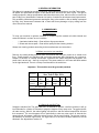
1
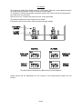
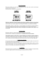
OPERATING and
SERVICE GUIDE
USA – 2-player
Coin in / Ticket out
Feature.
Produced by ;
Harry Levy Amusement Contractor Ltd
Unit 6 Patricia Way
Pysons Road Industrial Estate
Broadstairs
Kent
CT10 2LF
Tel 01843 866 464
Fax 01843 860 144
Issue 2 Sept 2010
CONTENTS
Section 1 – Contents
Section 2 - General Information
Section 3 - Commissioning
3.1 Maintenance
3.2 Receiving your machine
3.3 Self test
3.4 Tilt
3.5 Preparing the machine
3.6 Normal play
3.7 Feature game
Section 4 - Special Features
4.1 Swipe option
4.2 Pusher Motor controller
4.3 Counters
Section 5 - Access
5.1 General
5.2 Playfield
5.3 Lower cabinet
5.4 Cashbox compartments
5.5 Rear Cabinet
5.6 Top Sign
Section 6 - Electrical system
6.1 Fuses
6.2 Switch settings
6.3 Hoppers
6.4 Coin-in boards
6.5 Feature Boards
6.6 Motor Reset
6.7 Speaker
6.8 Lighting
6.9 Counters
6.10 Logic Boards
Section 7 - Mechanical systems
7.1 Pusher motor drive
7.2 Pushers
7.3 Coin entry chutes
7.4 Count & Payout (swipe) hoppers
Section 8 - Fault finding
Section 9 - Spare parts List
Page 2
2. GENERAL INFORMATION
This Manual is intended as a guide to servicing, fault finding and repairs on your Star Trek pusher.
All details and specifications shown in this manual were correct at the time of print. The right to
modify equipment, change specifications and instructions at any time, without notice is reserved as
part of Harry Levy Amusement Contractor Ltd. policy of continuous development and improvement.
Only qualified, professional personnel should gain entry to the machine, and no liability is accepted
by Harry Levy Amusement Contractor Ltd. or their staff for any damage or injury arising from the
use of this service manual.
3. COMMISIONING.
3.1 Maintenance
To keep your machine in optimum condition for maximum profit, maintain all visible internal and
external surfaces in a clean 'as new' condition.
·
·
1 Laminated cabinet body - Clean with an all purpose cleaner.
2 Glass and chrome parts - Clean with a quality window cleaning solution.
Always use cleaning products according to the manufacturers own instructions.
3.2 When you receive your machine.
Remove any transit packing materials from the machine then site your pusher on a smooth level
floor. Please handle your machine with care using appropriate lifting equipment, do not drop or
subject it to shocks, or a damp environment. Connect to the mains using the lead supplied. The
power inlet is at the rear – there is no top feed. The power switch is in the lower left hand cabinet
on the right hand wall. There is a 5 Amp circuit breaker in the switch box.
Important - This machine must be grounded (earthed).
Star Trek 2-Plyr USA
Machine
Voltage:
115
VAC
Freq:
60
Hz
Power:
300
W
Amps:
3
A
Overall weight
Kg
lbs
3.3 Switch On and Self Test.
Switch the machine ON. The game will wait ~10 seconds to perform a self test, and then it will go
into Tilt mode for a further 10 seconds to purge the hoppers of any stray coins. The pusher boxes
will start moving. After tilt, the mains lighting will switch on and the feature lamps/LEDs will start
their sequence. The count hoppers will run periodically to clear any stray coins. At intervals the
attract sounds will operate. Adjust the volume level to suit the surroundings. The volume is set by
dip-switches on the main logic board. The logic board is in the lower left hand cabinet on the left
hand wall. See dip switches section 6.2.
Page 3
3.4 Tilt.
There are tilt sensors inside each lower door, on the end walls and a single pendulum device in the
top sign. Banging the machine will sound the alarm. All count hoppers will run. Any coins that fall
from the playfields into the count hoppers will be discharged into the swipe hopper or cashbox but
no tickets issued. The tilt will continue for approximately 10 seconds, or until all hoppers are empty.
The machine then reverts to its normal attract mode.
3.5 Preparing the Machine.
After checking the machine functions correctly each playfield will require approximately 600 coins
to float or prime it ready for play. The first 90% of the coins may be hand placed in small batches
onto the moving pusher box, allowing the machine to spread them onto the main playfield. The
final 10% of coins (and winnings) should be played into the machine through the coin entries.
3.6 Normal Play.
When a player inserts a coin it passes a sensor that switches that section on, enabling the playfield
winnings system to make legitimate awards. The section remains enabled for approximately 30
seconds. A coin counter records each coin inserted.
If tilted or bumped whilst being played the tilt system takes over the entire machine. Coins falling
from the playfield are ignored and no tickets will be issued.
3.7 Feature Game.
When a player inserts a coin, it runs down the pin Perspex to a row of characters, each with a flag
opto sensor in the coin channel. The feature is divided in two; left and right, with a divider down the
centre of the Perspex. The player can play both sides at once through the two coin chutes, or
concentrate on one side only. Above each character is a Red LED. These highlight the current ‘live
targets’, one each side. If the coin triggers a characters’ opto sensor when the Red LED is lit the
player scores a hit and wins tickets. The character remains lit.
Lighting all four characters sounds a ‘4 crew bonus winner’ message and awards tickets.
Lighting all four characters on the other side sounds an ‘8 crew bonus winner’ message and
awards more tickets. The feature will then clear and start again.
When all 4 characters are lit, they can be ‘knocked out’ by further coins, and then ‘hit’ again. In this
case, the character win tickets are awarded, not the ‘4 crew’ tickets.
If a character is knocked off one side, and all 4 characters hit on the other side, the player gets
only the 4 crew win, not the 8 crew win. Thus it is better to play one side then the other to win
maximum tickets.
4. SPECIAL FEATURES
4.1
Swipe option
The machine has the option of being fitted with a swipe system to each section.
The swipe system allows players to obtain coins / tokens for the machine by using a swipe card.
Once ‘swiped’, coins / tokens for play will be dispensed to the player via the paycup.
4.2
Pusher Motor controller
The pusher box motor is controlled from the logic board. If the motor should jam for any reason,
the motor will stop and the alarm will sound. Clear the jam and push the reset button to restart. The
reset button is recessed in the rear of the machine on the left. It is visible from inside the coin entry
area at the left rear of the left hand player station.
Page 4
4.3
Counters.
There are three counters per section to count coins-in, tickets-out & swipe coins. The counters are
located inside the upper cabinet doors.
5. ACCESS.
5.1 General
With the exception of refilling tickets & hoppers, always disconnect the machine from the mains
supply by removing its plug from the supply socket.
Locks supplied are 301 for all locks except the cash boxes, which are 201.
5.2 Playfield.
Release the locks on the glass window and lift it carefully out of the machine. Place the glass
somewhere safe for temporary storage.
5.3 Coin Entry area
Release the locks on the upper door, hinge back and lift out.
This gives access to:
Coin-in board
Counters
Mains lighting
Coin chutes
5.3 Lower Cabinet.
Each player section has an access door below the playfield which can be fully removed by
releasing the locks at the top of the door.
This gives access to:
Ticket Dispenser
Count & Payout (swipe) hoppers
Paycup
Logic Board
5.4 Cash box compartments.
Each player section has an access door below the pay-cup which can be fully removed by
releasing the lock at the top, and lifting the door out. This gives access to a lockable cashbox.
5.5 Rear Cabinet
Release the locks at the top of the rear door. Pull back and lift clear.
This gives access to:
Power Supply
Pusher Motor and Drive System
Feature Board
Page 5
5.6 Top Sign
There are eight screws on the cabinet roof holding the front roof section that keeps the artwork in
place. Remove the screws, lift the loose section out and remove the artwork
This gives access to the following:
Top sign lighting
Pendulum tilt
Alarm screamer
6. ELECTRICAL SYSTEMS.
The mains inlet plug is recessed in the rear of the machine. There is no top feed facility.
The mains 110v power switch is located in the right hand station on the right hand wall.
The mains wiring is all double insulated in the cabinet base. The motor and drive belts are shielded
with insulated dividers.
6.1 Fuses
The mains switch housing incorporates a 5 Amp reset type fuse.
The power supply box also incorporates reset type fuses of various values to protect the various
low voltage wiring and systems from excess current. See wiring diagrams for details.
6.2 Switch Settings
Logic Board
Program
SW1
SW1
Pole
Pole
ST14540 U1
1
off
off
off
off
on
on
on
on
2
off
off
on
on
off
off
on
on
3
off
on
off
on
off
on
off
on
Sound volume
Min
4
0
1
Game position Save in attract
Game position lost
Game position retained
Factory Setting
max
Page 6
SW1
Poles 5
off
off
off
off
off
off
off
off
on
on
on
on
on
on
on
on
6
off
off
off
off
on
on
on
on
off
off
off
off
on
on
on
on
7
off
off
on
on
off
off
on
on
off
off
on
on
off
off
on
on
8
off
on
off
on
off
on
off
on
off
on
off
on
off
on
off
on
Swipe coins issued
0
Factory Setting (Swipe not fitted)
1
2
3
4
Factory Setting (Swipe Ready)
5
6
7
8
9
10
11
12
13
14
15
SW2
poles 1
off
off
off
off
off
off
off
off
on
on
on
on
on
on
on
on
2
off
off
off
off
on
on
on
on
off
off
off
off
on
on
on
on
3
off
off
on
on
off
off
on
on
off
off
on
on
off
off
on
on
4
off
on
off
on
off
on
off
on
off
on
off
on
off
on
off
on
Tickets per coin won
0
1
2
3
4
5
6
7
Factory Setting
8
9
10
11
12
13
14
15
SW2
poles 5
Off
Off
On
On
6
off
on
off
on
Mercy Tickets issued per coin-in
0
1
Factory Setting
2
3
SW2 pole
SW2
Pole
7
Off
On
Payout table select
pays 2 – 16 – 40
pays 4 – 16 - 32
Factory Setting
8
Reset
off
normal operation
on
clear ticket payout registers. Power-up game with dipswitch on.
Press the Pusher motor Reset button within 1 minute. Switch the machine Off. Set
SW2 pole 8 Off. Switch the machine On.
Page 7
6.3 Hoppers
The hoppers are Asahi Seiko SH400 running in ccTalk mode. Each has a unique address which is
set by dip-switches inside the ccTalk box on the end of the hopper.
To access the ccTalk box dip-switches, switch the machine off. Remove the two securing screws –
one at the front; one at the side.
Remove the cover. It needs to be coaxed over the 10.way pin header.
The dipswitch settings for all four hoppers are as follows:
If the game is not set up for swipe, ignore the payout hopper settings:
The switch slider is denoted by the Black square in these diagrams.
Always ensure that the dipswitches are set correctly or the communications system will not
function.
Page 8
6.4 Coin Entry Board
Each player station has a coin-entry board fitted in the coin entry area, and the two twin-opto
sensors connect to this board.
Each board has an address set by dipswitches:
Signals are validated such that all forward moving coins are treated as valid coins: any reverse
moving coins are seen as a fraud attempt and the game goes into tilt mode, thus negating any
coin-in tickets or any award in progress, and alerting the attendant to a possible fraud attempt.
These boards operate in ccTalk mode. In normal operation the small blue on-board Led flashes
continually, showing that the main logic board is interrogating the coin entry board for activity.
The prototype boards are fitted with a variety of housings to accommodate a wide range of opto
sensor types.
6.5 Feature Board
Each player station has a feature board fitted to the rear of the pin-perspex.
Each board has an address set by dipswitches - the same as the coin entries above.
These boards operate in ccTalk mode. In normal operation the small blue on-board Led flashes
continually, showing that the main logic board is interrogating the feature board for activity. In
attract mode the lit Leds and lamps are shuffled around under control of the feature board. When a
coin is inserted, the Leds and lamps now come directly under the control of the main logic board.
6.6 Motor jam reset switch.
The motor jam alarm can be manually reset by pressing the reset button located on the rear left of
the machine, at the coin entry area height.
If the jam alarm sounds often or for no apparent reason this indicates that the motor is running
slowly for some reason, i.e. the drive mechanism needs adjusting. If the game tilts frequently for no
reason, one of the slam tilts or pendulum needs adjusting.
6.7 Speakers.
Each section has its own speaker in the top of the coin entry areas. If a speaker is suspected faulty
it should be replaced with one of the same type and rating, use 8 Ohm 15 Watt.
Page 9
6.8 Lighting
There are two mains voltage fluorescent lamps in the top sign, one in each coin entry area, and
one above each playfield.
6.9 Counters
Electro-mechanical counters are included to enable you to monitor the performance of your
pusher, and check the accounting.
Counters are incorporated for coins-in, ticket-out and swipe coins out.
6.10 Logic Boards
These are custom made to perform the functions necessary for correct operation of the machine.
In general they are not user serviceable and should a fault arise they should be sent back to your
distributor or Harry Levy Amusement Contractor Ltd for repair.
7. MECHANICAL SYSTEMS.
7.1 Pusher motor drive.
The main drive motor is situated beneath the playfield. It connects directly to the right hand pusher
box driver spindle, and connects to the left hand via a drive belt.
Check the belt after one months operation, and thence annually.
As long as the pusher box slides are kept clean and lightly greased the system will give many
years of reliable service.
A fail-safe cut-out is included on the motor to protect it from stall conditions. The motor shaft
rotation is monitored by an opto sensor. If the system suffers a mechanical jam the reduced speed
will be detected and the supply to the motor will be turned off. The alarm will sound. Switch the
machine off, remove the cause of the jam and switch the machine on again. If the jam self cleared,
pressing the reset button will re-start the motor.
The sensitivity of the monitoring system is fixed in this installation.
7.2 Pusher boxes.
The pusher boxes are mounted on two Accuride slide bearings. An annual check to remove any
build up of dust and a light coat of grease will ensure many years of reliable service.
Ensure that the coin scraper system is fully intact and working smoothly and freely, replace any
suspect parts.
7.3 Coin entry Chutes.
Each player section has two coin entry chutes. The chutes are fitted with twin opto sensors to
detect coins and prevent strimming. Other than keeping the chutes clear and clean no
maintenance is required.
7.4 Count & Payout (swipe) Hoppers.
Each player section is fitted with a count hopper and, if fitted, with a swipe payout hopper. Coins
falling from the playfield fall down the win chute into the count hopper. The count hopper then
counts the coins into the cash box or payout hopper. Once the payout hopper is full coins overflow
to the cashbox. If the machine is tilted, coins falling into the count hopper will be evacuated but not
counted, and no award will be paid. This state remains until the tilt is removed.
Page 10
If the machine is fitted with a swipe system the payout hopper will dispense coins to the player
when the section is ‘swiped’. If a particular section is swiped continuously the swipe hopper may
run low on coins. If this happens, the hopper / swipe system for that section is temporarily disabled
until the minimum level of coins is replenished from the playfield.
Note - Each player section works independently of the other sections.
If a fault is suspected first check for mechanical jams (a coin stuck), and rectify as appropriate.
If removal of the hoppers is required, power down the machine before disconnection /
reconnection. Failure to do so can damage the hopper opto.
Remember that these hoppers have dipswitches inside, and if you change them around for testing
purposes, remember to set the dipswitches accordingly.
8. FAULT FINDING
It is of mutual interest that your pusher is kept in excellent working condition, therefore when
required please order original replacement parts from your distributor or Harry Levy Amusement
Contractor Ltd.
If a fault occurs with any electrical system: SWITCH THE MACHINE OFF. Check that :a) There is a suitable mains supply.
b) All reset fuses are intact (they pop out if overloaded, push to reset).
c) All plugs and sockets are correctly mated.
d) No wires are trapped, damaged or broken.
e) All wires are properly secured to their terminals and pins.
Wiring check.
A visual inspection will reveal the general condition of the wiring. A more thorough test using a
continuity tester will be needed to check apparently intact wires, however once a machine has
been playing successfully for some time wiring is not usually at fault.
Device testing.
Disconnect the machine from the mains supply then check the physical condition and operation of
the suspect device (remove from the machine if necessary). Bench test if possible using a suitable
power supply.
In general PCB's are not user serviceable. Should a problem develop indicating a board fault it is
recommended that the board is returned for repair to your distributor.
Fault diagnosis and repair may be performed by skilled service personnel, but this may invalidate
the warranty.
Page 11
Systems checking.
When a fault occurs that affects the whole of the machine, the power supply and regulation system
should be investigated first.
Check the input, and output fuses.
Refer to schematics and drawings to check power connections, voltages etc.
If the fault is not visual, or easily measurable it is often helpful to disconnect the outputs from the
PSU, check that the PSU is functioning then connect the loads one at a time.
It is easy to identify the faulty system, then use a similar technique within that system (such as
disconnecting all hoppers) to identify the faulty component.
Symptom
Possible Fault
Will not start
Mains switch OFF
Fuse popped
Check mains switch is ON
Check plug fuse then internal fuses.
No sound
Volume
Speaker
Logic Board
Adjust volume
Check wiring. Replace if faulty
Replace board if faulty.
Light failed
Tube failed
Check end caps & wiring
Replace tube.
Replace with same type.
Replace with same rating.
Remedy
Starter failed
Choke (ballast) failed
Pusher boxes not moving
Power to motor
Mechanical jam
Check power & connections.
Check for coins or
Foreign matter causing jam.
Clear & reset.
Tilt alarm not working
or on continually
Pendulum stuck
Door tilt sensor
Sounder
Check pendulum & adjust.
Check & adjust.
Test connections & power
Counter(s) not working
Wiring
Counter
Opto sensor
Check connectors & loom
Bench test / replace.
Check every opto sensor.
Top sign not working
Power disconnected
Check connectors
Page 12
9. SPARE PARTS LIST
There is a description and Harry Levy Amusement Contractor Ltd stock number to help you identify
the part you require. Please quote the description and our stock number when ordering. Thank
you.
Description
201 lock & keys
301 lock & keys
Accuride pusher box slide
Circuit Breaker 3 Amp
Circuit Breaker 5 Amp
Coin-in PCB
Counter
Drive Belt
Electronic alarm board
Feature PCB
Filter - Mains 6A
Hopper – over edge
Hopper – payout
Motor
Motor Capacitor 5uF
Motor opto board
Opto sensor - coin in
Pluto 5 Logic PCB
Power Supply Unit - 12v
Power Supply Unit – 24v
Power Supply Unit – Comms -12v
Solid State Relay PCB
Speaker
Switch – key
Switch - reset
Switch - pendulum tilt
Switch - tilt
Swipe Relay PCB
Harry Levy Stock Number
6278
6087
6081
8879
8881
23855
6029
6856
7819
25279
8178
23870
23871
8567
8530
8318
8392
22573
8859
8860
23858
8353
6979
6610
6127
CC004
6534
8641
Many other items are available on request.
Manuals/Star Trek/2-Player Manual USA Feature
Page 13