1
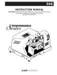
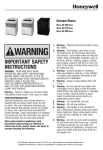
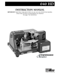
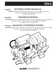
029A
INSTRUCTION MANUAL
IMPORTANT! Read these instructions before using the new 029A Key Machine.
Ensure that all safety recommendations are followed!
®
This manual is registered and applies specifically to
the machine which carries this serial number. It
properly identifies your model and assures you will
receive correct parts, if and when you require
replacement parts. Retain this manual in a safe place.
service manual should accompany the machine.
When seeking service information about this machine,
refer to Model No. (which is 029A) and the part
number desired (see pages 6 to 8). Note that many
parts are not interchangeable with other ILCO
UNICAN machines.
If ownership of this machine is transferred, this
CONTENTS
Warranty . . . . . . . . . . . . . . . . . . . . . . . .2
Safety information . . . . . . . . . . . . . . . .3-4
Introduction to the 029A . . . . . . . . . . . . .5
Operating parts (illustrated) . . . . . . . . . .6
Operating parts identification (names and
part numbers) . . . . . . . . . . . . . . . . . . . . .7
Exploded view . . . . . . . . . . . . . . . . . .8-9
Exploded view parts list . . . . . . . . . . . .10
Unpacking . . . . . . . . . . . . . . . . . . . . . .11
Proper Key Cutting Techniques . . . . . . .11
Four-Way Vise Jaws . . . . . . . . . . . . . . .12
Key Alignment - Duplicating . . . . . . . . .13
The Cutting Operation . . . . . . . . . . . . . .14
Cutting Keys by Code . . . . . . . . . . . . . .15
Key Alignment - Code Cutting . . . . . . . .16
The Cutting Operation . . . . . . . . . . . . . .17
Replacing the Cutter/Adjustment . . . .18-19
ONE YEAR LIMITED WARRANTY
ILCO UNICAN warrants to the original buyer of any
new model 029A machine that it will repair or
replace, at its option, any part of any machine which
proves, to the reasonable satisfaction of ILCO
UNICAN, to have defects arising from the faulty
manufacture of the machine or from defective
material or components, during a period of one (1)
year from the date of shipment of the machine by
ILCO UNICAN, provided that the machine is
returned by prepaid transport to ILCO UNICAN or
to its authorized representative before the expiry of
the warranty period together with a detailed
description of the alleged defect(s). ILCO UNICAN
may, at its discretion, elect to refund the purchase
price allowable to the part affected, or to issue a
credit if the price therefore remains unpaid.
ILCO UNICAN sells precision-made machines. The
buyer assumes all risks, and ILCO UNICAN shall
not be liable for any reason, if the machine has been
subjected to improper installation, improper use,
improper or inadequate maintenance, negligence, if
any unauthorized modification or alteration is made
to the machine, or in case of accident. For greater
certainty, any machine not operated in accordance
with ILCO UNICAN’s printed instructions or
operated beyond its rated capacity shall not be
covered by this or any other warranty.
2
Any and all warranties made by ILCO UNICAN on
any machine, product, or component thereof shall be
effective only if and for so long as the buyer complies
with all payment obligations pursuant to the buyer’s
accepted and acknowledged order. Failure to meet
such payment obligations shall void all warranties
and not extend the period of time for which such
machine, product of component thereof is warranted
irrespective of whether or not payment is eventually
made.
These warranties are in lieu of and not in addition to
any other warranty of condition, expressed or implied,
including without limitation merchantability, fitness
for a particular purpose or latent defects. The buyer
releases ILCO UNICAN from any liability for any
reason other than a breach of its warranties
hereunder.
The liability of ILCO UNICAN shall in no case,
including negligence, exceed the purchase price of the
defective machine, nor shall ILCO UNICAN be liable
for any personal injuries, property damage or
consequential damages.
Use only genuine ILCO UNICAN replacement parts
on this machine!
Serial number : ____________________
WARNING – SAFETY NOTICE
IMPORTANT - Please read carefully before operating machine.
Safety begins with education, and continues with proper
application. All personnel who operate your machine
should read the supplied Operator’s Manual for
information on how to properly operate it. The likelihood
of accidents and miscuts will be greatly reduced.
General safety
• Safety glasses must be worn to reduce the
possibility of eye injury while operating or in the
immediate vicinity of key cutting equipment.
• Always turn machine off before making
adjustments or inserting or removing keys.
• Machine should be located in an area accessible
only by authorized operators. Location must be
such that customers and other personnel are not
subject to potential injury from “flying chips”.
• Do not defeat safety features built into your
machine. Removal or modification of safety shields,
cutter guards, and other safety devices should be
strictly forbidden.
• At no time should the mechanically-driven parts of
the machine be touched while it is in operation.
The operator should take care to ensure that loosefitting clothing, long hair, etc. are kept from the area
of machine operation.
• Your machine has been specially designed and built
for key cutting purposes only and should be
operated according to the Operator’s Manual. All
other uses are strongly discouraged as potentially
dangerous, and should not be attempted! Such use
will immediately void the machine’s warranty.
• Some states have specific age restriction concerning
the operation of certain types of equipment. Check
local and state ordinances for compliance.
Electrical safety
• (120 Volt models) Your machine is designed to
operate using 120 Volt A.C. 60 Hz. electrical
current. It is supplied with a three-prong power
plug which should be used with a properly
grounded three-prong outlet only. Do not defeat the
safety purpose of the plug by modifying or using
with non-grounded outlets!
• To reduce risk of fire or electrical shock, do not expose
or operate machine in damp or wet locations.
• Electrical problems should be referred to qualified
repair technicians. If the machine is under
warranty, contact Ilco Unican at the address
printed on the cover. (ILCO UNICAN also offers
repair service for out-of-warranty machines.
Contact ILCO UNICAN for details.)
• Always unplug the machine before removing the
hood or changing the cutter wheel.
Grounding instructions
• In the event of a malfunction or breakdown,
grounding provides a path of least resistance for
electric current to reduce the risk of electric shock.
This machine is equipped with an electric cord that
has an equipment-grounding conductor and a
grounding plug. The plug must be plugged into a
machine outlet that is properly installed and
grounded in accordance with all local codes and
ordinances.
• Do not modify the plug provided - if it will not fit
the outlet, have the proper outlet installed by a
qualified electrician.
• Improper connection of the equipment-grounding
conductor can result in a risk of electric shock. The
conductor with insulation that has a green outer
surface (with or without yellow stripes) is the
equipment-grounding conductor. If repair or
replacement of the electric cord or plug is
necessary, do not connect the equipment-grounding
conductor to a live terminal.
• Check with a qualified electrician or service
personnel if the grounding instructions are not
completely understood, or if in doubt as to whether
the machine is properly grounded.
• Use only 3-wire extension cords that have 3-prong
grounding plugs and 3-pole receptacles that accept
the machine’s plug.
• Repair or replace damaged or worn cords
immediately.
3
PAGE HEADING
CONSIGNES
DE SÉCURITÉ
IMPORTANT : Veuillez lire attentivement ce qui suit avant d'utiliser la machine.
La sécurité commence avec la prévention et se
poursuit en agissant prudemment. Tout le personnel
qui utilisera cette machine devrait lire le guide
d’utilisation fourni afin de savoir comment faire
fonctionner la machine. Les chances d’accidents et de
clés mal taillées seront grandement réduites.
Sécurité générale:
• Toujours porter des lunettes de protection lorsque vous
vous trouvez à proximité de la machine à tailler les clés
en marche ou lorsque vous l’utilisez afin de réduire tout
risque de blessures aux yeux.
• Toujours arrêter la machine avant de la régler ou
d’insérer ou de retirer des clés.
• Placer la machine dans un endroit réservé uniquement
aux utilisateurs. cet endroit devra être tel que la
clientèle et le reste du personnel seront protégés contre
les risques de projection de copeaux susceptibles de
causer des blessures.
• Ne pas modifier aucun dispositif de sécurité installé sur
cette machine. Il est strictement défendu de modifier ou
d’enlever l’écran de protection, les protecteurs de la
fraise ou tout autre dispositif de sécurité.
• Ne jamais toucher aux pièces mécaniques
d’entraînement lorsque la machine fonctionne.
L’utilisateur ne doit pas non plus porter des
vêtements amples et doit avoir les cheveux attachés
lorsqu’il se trouve à proximité de la machine.
• Cette machine a été conçue et fabriquée
uniquement pour tailler des clés et doit être utilisée
tel que décrit dans le guide d’utilisation. Il serait
dangereux d’essayer d’utiliser cette machine à
d’autres fins. Ceci aurait pour conséquence de
rendre nulle la garantie de la machine.
• Certaines provinces imposent des restrictions d’âge
pour certains types de machines. Vérifier auprès
des autorités locales et provinciales pour être
conforme à la loi.
Sécurité électrique :
• (Modèles 120 volts) Cette machine est conçue pour
fonctionner à l’électricité sur du 120 V-c.a. à une
fréquence de 60 Hz. La machine est munie d’un câble
électrique à fiche tripolaire lequel ne doit être utilisé
qu’avec une prise de courant tripolaire. Ne pas
modifier la fiche du câble et ne pas l’utiliser dans une
prise de courant non reliée à la terre (polarisée).
• Afin de réduire les risques de feu ou de chocs
électriques, la machine ne doit pas être exposée à
l’humidité ou à l’eau.
• Seuls des techniciens qualifiés doivent procéder
aux réparations d’ordre électrique. Si la machine
est sous garantie, communiquer avec ILCO
UNICAN (adresse, no de téléphone et no de
télécopieur sur la page couverture). ILCO UNICAN
offre également un service de réparation pour les
machines dont la garantie est expirée.
• Toujours débrancher la machine avant d’enlever le
couvercle ou de changer la fraise.
Directives de mise à la terre
Le conducteur dont la surface extérieure de l’isolant est
verte (avec ou sans rayures jaunes) constitue le
conducteur de protection. Si le câble électrique ou la
fiche doit être réparé ou remplacé, ne pas brancher le
conducteur à une borne sous tension.
• Advenant le mauvais fonctionnement ou une panne de
la machine, la mise à la terre fournit un trajet de
moindre résistance pour le courant afin de réduire tout
risque de chocs électriques. Cette machine est munie
d’un câble électrique équipé d’un conducteur de
protection et d’une fiche de terre. La fiche doit être
branchée à une prise de courant correspondante
adéquatement installée et reliée à la terre conformément
aux codes et aux règlements locaux.
• Vérifier auprès d’un électricien ou du personnel de
service si vous ne comprenez pas les directives de mise
à la terre ou si vous avez des doutes quant à la mise à
la terre adéquate de la machine.
• Ne pas modifier la fiche. Si elle ne correspond pas à la
prise, vous adresser à un électricien pour installer la
prise adéquate.
• Utiliser seulement des prolongateurs trifilaires munis
de fiches et de prises tripolaires acceptant la fiche de la
machine.
• Le raccordement inadéquat du conducteur de protection
peut entraîner des risques de chocs électriques.
• Réparer ou remplacer immédiatement les câbles
endommagés ou usés.
4
INTRODUCTION
Congratulations!
You’ve purchased a superior key cutting machine.
The model 029A code/duplicating machine is designed
for maximum versatility and convenience. Its “dual
function” design allows the operator to originate a key
by code where necessary, or duplicate an existing key
when available.
double sided automotive keys can be duplicated or code
cut with ease; the four-way jaws include stations ideally
suited to gripping these keys and is capable of gripping
them in the groove or milling for enhanced performance
when necessary (see illustration on page 12.)
The machine features exclusive four-way vise jaws
designed to accommodate virtually any standard
automotive key without the need for adapters. Even
Accurate, easy to operate and maintain, the model 029A
delivers excellent performance at an economical price!
Unpacking instructions
Your 029A key machine has been shipped to you in a
sturdy, specially-cushioned container to prevent the
possibility of damage during handling and shipment.
Once the machine is removed from the carton, it
should be set up on a level workbench and wiped free
of all rustproofing oil. The machine is adjusted at the
factory and test keys have been cut on it, but it is
recommended that you check the adjustments to make
sure they have not slipped or shifted during transit
(see page 18 “Adjusting for depth of cut”).
Safety
The 029A has been engineered to duplicate/code cut
cylinder (paracentric) keys. It is not intended or
designed for any other purpose. The machine operator
assumes all liability when using this machine in a
manner inconsistent with its stated design purpose.
Refer to page 3 for complete safety information before
operating the machine.
ILCO UNICAN strongly recommends the use of
protective eye glasses or goggles when operating this
CAUTION!
machine, or when in the vicinity of the machine while
it is being operated. Protective eye wear prevents
injuries! The machine should be turned off before
loading or unloading keys.
When the key machine is operating, be careful not to
contact the vise jaw or carriage against the cutting
wheel as this will cause damage to the cutter, jaw, or
carriage.
DO NOT DESTROY OR DISCARD THIS VALUABLE SHIPPING CARTON.
STORE IT CAREFULLY IN A SAFE PLACE. THIS CARTON SHOULD BE USED
WHENEVER THE MACHINE IS MOVED OR SHIPPED.
5
OPERATING PARTS
Safety Hood
Cut Combination Display
Key
Gauge
Safety Shield
Cutter
Deburring
Brush
Wing
Nut
Depth
Knob
Vise Jaws
Carriage Handle
Carriage
Off/On Switch
6
OPERATING PARTS
OPERATING PARTS
IDENTIFICATION
Refer to page 6
Part No.
024B-1
029A-3X
025-8
045-23
CU29
814-00-51
029A-49
025-55
029A-56
025-62A
029A-86X
029A-87
Identification
Carriage
Vise Jaw Assembly (2)
Wing Nut (2)
Carriage Shaft
CU29 Cutter
Deburring Brush
Cutter Guide (stylus)
Adjusting Screw
Key Gauge
Off/On Switch
Safety Hood Assy.
Safety Shield
7
EXPLODED VIEW
8
EXPLODED VIEW
9
EXPLODED VIEW PARTS LIST
Refer to pages 6-7 for illustration
Ref.
Part no.
Description
1
1X
2
3X
4
6X
8
9X
20
21
23
32
36
37
38
40A
41
43
45
46A
47
48
49
53
54
55
56
57
58
59
60
61
62A
65
68
70
74
75
79
82
10
024B-1
024B-1X
025-2
029A-3X
025-4
025-6X
025-8
040-9X
025-20
025-21
024-23
024B-32
025-36
025-37
CU29
025-40A
025-41
814-00-5
025-45
025-46A
025-47
025-48
029-49
025-53
029-54
025-55
029A-56
024B-57
024B-58
025-59
025-60
025-61
025-62A
045-65
040-68
040-70
040-74
040-75
029A-79
025-82
Carriage
Carriage assembly
Carriage stud
Vise jaw assembly
Vise jaw spring
Thrust bearing set
Wing nut
Carriage handle
Cutter shaft bushing
Carriage shaft bushing
Carriage shaft
Button head. screw, 10-24 x 3/8”
Cutter nut, N-4
Cutter spacer
CU29 cutter
Cutter shaft
Cutter shaft pulley
Nylon brush
Brush bolt washer, 5/16
Hex head screw, 5/16-18 x 3/4
Motor pulley 2” - 3L
V-Belt, 3L-180
Cutter guide (stylus)
Cutter guide binding washer
Cutter guide binding screw
Adjusting screw
Key gauge
Key gauge bracket
Key gauge dowel pin
Key gauge housing
Cap screw, 8-32 x 1/2”
Circuit Breaker, ETA 1658
On/Off switch
Main Base, machined
Electrical cover
Rubber Mount
Truss head screw, 8-32
Motor, 1/4hp,115V
Key gauge spring
Oil cup
Ref.
Part no.
Description
86
86X
87
88
89
90
91
92
101
106
107
109
110
146
150
151
160
163
170
171
172
173
174
175
176X
183
184
194
195
198
199
IM
029A-85
029A-86X
029A-87
029A-88
045-89
025-90
024B-91
024B-92
025-101
040-106
029A-107
025-109
025-110
040-146
040-150
040-151
025-160
045-163
029A-170
025-171
029A-172
029A-173
029A-174
029A-175
029A-176X
040-183
040-184
045-194
045-195
045-198
045-199
029A-IM
Safety hood with 029A decal
Safety hood assembly
Safety shield
Shield screws, 10-32 x 1/2
Lock washer, #10
Nut, #10-32
Power cord
3 wire motor cable
Motor pulley set screw
Chip Tray
Spacer
Bearing washer
Wave washer
Power cord strain relief
Switch screw (6-32 x 1/4”)
Set screw (8-32 x 38”)
Caution label
Hood screw
Bushing Spacer
Cutter pulley set screw, 3/8” -18
Cut Combination Display
Cutter Guide Screw
Cutter Guide Lock Screw
Depth Knob Retaining Screw
Cutter guide Block Assy.
1/4" Lock washer
1/4-20 Hexnut
#10 Flat washer
10-32 x 1/2” Button hd. Screw
7/16-14 x 3/4” set screw
1/4-20 x 1/2” set screw
Instruction manual
NS
040-240
220V 1/4 HP motor
UNPACKING
UNPACKING
TEST KEYS
The 029A key machine is shipped completely assembled and pre-adjusted. Upon unpacking the machine,
locate the nylon band securing the carriage assembly
and cut it to allow the carriage to drop to its normal
“down” position. At this point, you should be able to
slide the carriage sideways.
A series of cut keys are supplied with your machine.
These keys were cut on your machine and represent the
result of our quality inspectors' work before approving
your machine for shipment. The keys are reproductions
of factory-dimensioned pattern keys and are accurate to
.002" or less. Save these keys and use them as
standards to check the accuracy of cuts in the keys you
make. Duplicating a key and then using a key
micrometer or caliper to compare the actual depth of the
cuts on both the duplicate and the pattern key will allow
you to see if your machine is cutting too deep or too
shallow, thus indicating that an adjustment of the cutter
guide is necessary.
PROPER KEY CUTTING TECHNIQUES
Even though your 029A key machine is designed to
make key cutting fast, efficient and accurate, operator
skill is important. The actual mechanics of placing
keys within the vise jaws is simple to learn, but there
are some basics that must be followed. A properly
adjusted key machine used by someone who ignores
good key cutting techniques will NOT produce a good
key. The way a person clamps a key into the vise jaws
is critical to the accuracy of the duplicated key.
Remember - the real purpose of a duplicate or code cut
replacement key is to operate the lock for which it was
intended. If customers return keys, you should
reexamine your cutting techniques and adjustment of
the machine.
Here are some important operating tips:
1. Vise jaws - clean them regularly so that no metal
chips lie under the keys. It is essential that both
keys lie flat across the entire width of each vise
jaw. Neither key should be tilted.
2. Do NOT use pliers or other tools to tighten the vise
jaws. Firm hand pressure is sufficient.
3. Keep the carriage shaft free of metal chips. A thin
film of oil can be applied to it. The carriage should
4.
5.
6.
7.
be free to move without binding.
NEVER touch the shoulder of a key to the side of
the cutter guide. This will cause the shoulder of the
key blank to touch the side of the cutting wheel.
When this happens, some of the metal will be cut
away from the shoulder of the key blank. If the
resulting duplicated key is duplicated two, three,
four times over, an error will accumulate and cause
a non-operating key. Do not grind away the shoulder.
Don't run the cutter into the vise jaw; this will dull
the cutter, and reduce cutter efficiency.
Keep the cutter clean. Don't let any foreign objects
or instruments blunt it. This cutter is a precise
cutting tool and should be handled with care.
Lubrication of moving parts is important. An oil cup
is provided to keep the cutter shaft bearings well
lubricated. The carriage spindle should be lubricated
with a thin film of oil and wiped free of chip build up.
The lubrication procedures should be performed
every 2-3 weeks depending on usage. (5-7 drops of a
lightweight machine oil such as “3-in-1” or
equivalent is sufficient for the oil cup.)
11
FOUR WAY VISE JAWS
The highly versatile ILCO UNICAN 029A is capable of
creating a key from a code number (cutting by code), or
copying a customer's existing key (duplicating). The
ultimate goal in either application is to produce an
accurately cut key that smoothly operates in the lock
cylinder it is intended. While the goal is the same, there
are important differences between code cutting and
duplicating. Please read the following sections of this
manual carefully!
Using the four-way vise jaws
Your 029A is equipped with the ILCO UNICAN versatile four-way vise jaws. They feature four unique
clamping surfaces to securely grip virtually any typical
cylinder key (see Fig. 1).
IMPORTANT: The correct vise jaw positions to use for
all lock applications covered by your 029A key machine
are listed in the Application Guide accompanying this
manual. It is important, especially for cutting keys by
code, that the vise jaw positioning indicated in the
Application Guide be used to assure accurate results.
A - For holding doublesided keys by gripping their
center groove(s).
Using A
position
B - For holding single-sided
automotive keys, as well as
most house and padlock
keys.
Using B
position
C - For holding certain keys,
Using C
such as most “Ford types”
position
by gripping along their
edge, allowing the “center
ridge” of the key to rest against the face of the vise.
Code - Specific to the left side vise jaw, this position is
used only when cutting keys by code. All spacing keys are
clamped using this position except for those used for
cutting single sided keys. Refer to the Application Guide
for vise jaw positioning instructions for specific key types.
To reposition the vise jaws, as from A to B, first loosen
the wing nuts. Then lift upward on the top and bottom
of each vise jaw as a complete unit to raise them above
their seat in the carriage. Rotate the jaws until the
chosen vise position is facing toward the rear of the
machine and lower the jaws back into contact with the
carriage. Both left and right vise jaws should be rotated
to the same position, except when cutting by code.
Figure 1 Rotate both jaws as a set
12
KEY ALIGNMENT - DUPLICATING
Aligning keys in the vise jaws for duplication
Keys with shoulders
WARNING: Do not install or remove keys unless
the off/on switch is in the off position.
After positioning the vise jaws to the proper setting, both
the pattern key and the key blank must be properly
aligned and securely clamped in the vise jaws. To do this,
slide the machine‘s carriage assembly towards the right
and position the appropriate key blank in the carriage’s
RIGHT vise jaw with the head of the blank pointing to
the left.
Aligning keys in the vise jaws for
duplication
Keys without shoulders
On keys such as the Ford double-sided key, which do
not have a conventional shoulder, the tip of the key is
used as the aligning point (see Fig. 3). Clamp the
blank key in first and move the machine carriage to
the left. Lower the key gauge and position the carriage
so the tip of the key blank touches the key gauge.
Install and align the pattern key in the left vise jaw in
the same manner.
Ensure that the shoulder of the key blank is roughly
aligned with the red mark on the vise jaw face. Verify
that the key blank is held level (not tilted), then
tighten the wing nut. Position the “original” or pattern
key in a similar manner into the LEFT vise jaw.
Next , lower the key gauge and position the carriage so
that the edges of the gauge contact the shoulders of
both the original and blank key at the same time.
You may have to loosen the wing nut securing one of
the keys and reposition it slightly. It is important
that the shoulder of both keys are in contact with
the gauge at the conclusion of this step.
Key Gauge
Tip
of key
Key Gauge
Figure 3
Shoulder
of key
Figure 2 - Aligning shoulders of keys with key gauge
13
THE CUTTING OPERATION
WARNING: Do not install or remove keys unless
the off/on switch is in the off position.
1. Set machine in duplication mode. This is
accomplished by positioning the depth knob in to
its deepest cut position. (This is the last number,
usually the highest, encountered as you rotate the
depth knob away from you.) At this point, push in
on the cutter guide until it stops and tighten the
locking screw in that position (See Fig. 4)
Position
Depth Knob
to its last
number
Push on cutter
guide and
tighten lock
screw
Figure 4
2. Rotate both vise jaws to the station suitable for the
key being duplicated.
3. Insert the blank key and pattern key into the vise
jaws using the appropriate method described
under “Aligning Keys in the Vise Jaws”. Be sure
that both keys are laying level in the vise jaws and
are not tilted.
4. Lower the key gauge to align the keys using an
appropriate method as described under “Aligning
Keys …” found in the previous section (see page 10).
5. After the keys are aligned, return the gauge to its
“up” position.
6. Press the off/on switch to the “on” position.
7. Lift the carriage with both hands (see Figure 5).
Figure 5
14
8. Move the carriage to line up the cutter guide with
the cut closest to the head on the pattern key. Do
not permit the cutter to touch the shoulder of key
blanks with shoulders.
9. Press in on the carriage, while guiding it to the left.
Carefully trace the cuts of the pattern key with the
cutter guide. The cutter will make a corresponding
cut in the key blank. When the cut closest to the tip
of the pattern key has been traced, retrace the cuts
by guiding the carriage to the right. This will clear
away any metal not removed during the initial pass
over the key blank. Again, on keys with shoulders,
do not allow the cutter to contact the shoulder.
10. Press the off/on switch to the “off” position.
Remove the blank key. Press the switch to the
“on” position and remove any burrs that remain
by contacting the key lightly against the deburring
brush. Return the switch to the “off” position.
11. Operating Tips - When duplicating a key, avoid an
irregular jerking motion in the movement of the
carriage. Acquire a smooth steady motion, using
both hands on the carriage to guide it. Apply the
same degree of pressure each time a key is
duplicated. Excessive pressure may cause “overcutting”. It is sometimes best to practice on a few
keys until the operator learns to impart a steady,
uniform pressure to the carriage.
CUTTING KEYS BY CODE
INTRODUCTION: In addition to duplicating keys the
model 029A using optional accessories, has the
capability of cutting keys by code.
The previous section covered the procedures used to
duplicate a key from an existing copy. Code cutting,
does not require a key to copy. Instead, notches (cuts)
are made in the key blank based upon the code
number supplied with the original key. Often this
number is found on an accompanying tag or break-off
tab. If this number is known, the original key is not
needed. But you do need the proper code chart, which
is a numerical listing of key code numbers. Listed
beside each key code number on the chart will be a
corresponding series of digits which is the key cut
combination for that particular code; in short, the
actual cuts which should appear on a given key.
There are two critical dimensions in code cutting spacing of the cuts and depth of the cuts. Spacing
refers to where the cuts are placed along the blade of the
key “laterally”. The component which controls the
spacing dimension when cutting a key by code using the
model 029A is call a spacing key. Spacing keys are
either “tip stop” or “shoulder stop” in design (see Fig.
6). This indicates how a particular spacing key and key
Shoulder gauged spacing key
IMPORTANT: Refer to the Application Guide to
determine which specific spacing key and depth
knob to use for a given application. Each spacing
key is stamped with “SK” - followed by a 3 digit
number; depth knobs are stamped with letters to
aid in identification.
CUTTING KEYS BY CODE - PROCEDURES
Application Guide
The Application Guide that accompanies your
machine is a very important item when cutting keys by
code. Its most important function is to specify which
depth knob, spacing plate, and key blank is required
for a specific lock application. It also will indicate the
proper vise jaw position required to properly grip the
key blank for code cutting.
Changing the Depth Knob
When referring to the Application Guide you may find
that the key you wish to make requires a depth knob
different from the one already on the machine. Changing
the depth knob is easy; simply remove the retaining
screw (see Fig. 8) and slip the current depth knob off by
Retaining Screw
Tip gauged spacing key
Figure 6
blank should be aligned prior to cutting. The series of
cuts found on a spacing key are numbered and
correspond to the correct order in which cuts will be
made to the key blank. This will be fully explained later.
Depth refers to how deeply the notch (cut) is made
into the blade of the key. The
component which controls
the depth dimension for code
cutting purposes is called the
depth knob (see Fig. 7).
There are a series of numbers
which circle a depth knob.
These digits correspond to
the digits found beside a code
number on a code chart.
Depth
Knob
Figure 8
pulling it to the left. Install the selected knob by aligning
the slot on its right side with the pin projecting up from
the shaft it attaches to. Reinstall the retaining screw
finger tight, and the change is complete.
Vise Jaw Positioning
The 029A is equipped with “four-position” vise jaws.
The proper vise position to use (Code, A, B, etc.) will be
indicated in the Application Guide for each key listed.
It is IMPORTANT to remember that both vise jaws
should be set to the positions indicated in the booklet.
Figure 7
15
KEY ALIGNMENT - CODE CUTTING
Aligning keys in the vise jaws for code
cutting keys with shoulders
Aligning keys in the vise jaws for code
cutting keys without shoulders
WARNING: Do not install or remove keys unless
the off/on switch is in the off position.
On keys such as the Ford double sided key, which do
not have a conventional shoulder, the tip of the key is
used as the aligning point (see Fig. 10). Clamp the
blank key in first and move the machine carriage to
One difference between duplicating keys and code
cutting them is that the vise jaws are not always
positioned to the same stations or sides. The LEFT
and RIGHT vise jaws should be positioned to the
settings indicated in the Application Guide.
After positioning the vise jaws to the proper setting,
both the spacing key and the key blank must be
properly aligned and securely clamped in the vise
jaws. To do this, slide the machine's carriage assembly
towards the right and position the appropriate key
blank in the carriage's RIGHT vise jaw with the head
of the blank pointing to the left.
Ensure that the shoulder of the key blank is roughly
aligned with the red mark on the vise jaw face. Verify
that the key blank is held level (not tilted), and tighten
the wing nut. Position the appropriate Spacing Key in
a similar manner in the Left vise jaw.
Next, lower the key gauge and position the carriage so
that the edges of the gauge contact the shoulders of
both the Spacing Key and the blank key at the same
time. You may have to loosen the wing nut securing
one of the keys and reposition it slightly. It is
important that the shoulder of both keys are in
contact with the gauge at the conclusion of this step.
Edge of
Gauge
Shoulder
of key
Figure 9
16
Red
Mark
Figure 10
the left. Lower the key gauge and position the carriage
so the tip of the Ford key touches the key gauge.
Install and align the spacing key in the left vise jaw in
the same manner.
THE CUTTING OPERATION
To make the process of cutting by code easier to
understand follow the step-by-step example provided
below.
WARNING: Do not install or remove keys unless the
off /on switch is in the off position!
Scenario: A key needs to be cut by code from key code
#10J4 for a General Motors vehicle. The proper code
chart for this code series has been accessed and it
indicates the key cut combination for key code 10J4 is
355331. With this information known, it is possible to
continue the steps needed to create a working key from
this number.
1. Refer to the Application Guide and “look up” by
vehicle brand and model the code series containing
the code number needed. The Guidebook will list the
proper Depth Knob, Spacing Key, key blank, and vise
jaw position for the application selected.
2. Install the depth knob indicated by the Application
Guide onto the model 029A. In the example above,
the specified Depth Knob is “A”.
3. Rotate both vise jaws to the position specified (wide).
4. Ensure that the cutter guide lock screw is loosened
to allow the guide to spring forward (see Fig. 11).
5. Clamp the Spacing Key (SK-100) and key blank
Figure 12 - Rotate thumb wheels on display to change
numbers shown
10. Rotate the Depth Knob to the number that
corresponds to the first number of the desired key
cut combination. In our example, 355331, this
number would be “3’(see Fig. 13).
11. Lift the carriage with both hands and position it so
Depth Knob
Depth Index Mark
Figure 13
that the cutter guide is directly in front of the cut
on the Spacing Key marked “1” (see Fig. 14).
12. Apply moderate pressure to enable the cutter
Cutter Guide
Lock Screw
Cutter Guide
Figure 11 - Loosen Cutter Guide Lock Screw to allow guide
to spring forward for code cutting
6.
7.
8.
9.
specified for the intended application into the vise
jaws. (Refer to Application Guide for proper vise jaw
positioning.)
Lower the key gauge to align the spacing key and key
blank using the appropriate method as described
under “Aligning keys…” found in the previous section
(see page 17).
After they are aligned, return the gauge to its “up”
position.
The key cut combination for the sample key is
355331. Enter this number on the key cut display (see
Fig. 12). This device provides an easy to read display
of the number and can be referred to as the key is cut.
You are now ready to begin cutting the key!
Press the off/on switch to the “on” position.
Spacing
Key
Figure 14
guide to enter into the “1” cut on the spacing key.
As you apply pressure, the cutter guide, which is
spring loaded, will retract enabling the key blank
to contact the cutter and thus create the first cut of
the key cut combination. Use a “straight in straight out” cutting action.
13. Allow the carriage to return to its “rest” position.
17
THE CUTTING OPERATION (CON'T)
14. Rotate the Depth Knob to the number that
corresponds to the second number of the desired
key cut combination. In our example 355331, this
number would be “5”.
15. Repeat step 12, but position the cutter guide into
the “2” cut on the spacing key instead. In essence,
the numbered cuts on the spacing key correspond
to the proper location where each cut of the key
cut combination should be placed. Therefore, the
third cut of key cut combination 355331, which is
a “5”, will be created using the #3 position on the
spacing key and so on. Remember the Depth
Knob controls the depth of a cut, the Spacing
Key determines its location!.
16. Once each cut of the key cut combination has
been produced onto the key blank, remove it after
first ensuring the machine's off/on switch is in the
“off” position. In the case of a double sided key,
reclamp the spacing key and key blank as was
initially done. Repeat steps 9-16.
17. To deburr the completed key, press the off/on
switch to the “on” position and contact the key
lightly against the deburring brush. Return the
switch to the “off” position.
REPLACING THE CUTTER/ADJUSTMENTS
Replacing the Cutter
Adjusting for Depth of Cut
The CU29 cutter used on this machine is 2 1/4" in
diameter. It is specially designed for versatility and can
be used to duplicate and code cut most automotive
type keys. No warranty is placed on the cutter,
operators should treat it with care and avoid harsh
usage. Do not force the carriage up, causing the key
blank to bang into the cutter, and do not apply heavy
pressure when cutting. Also, do not let the cutter run
into the vise jaw; this will dull the cutter quickly.
To ensure safety, UNPLUG machine from its power
source before adjusting for depth of cut. It is imperative
that the cutter guide and cutter operate in the same
plane, that is, aligned to each other. If the cutter guide
is adjusted too far forward, the resulting cuts in a key
blank will be too shallow and the keys cut will not
work. Likewise, if the cutter guide is “behind” the
cutter, the cuts in the key will be too deep.
1. To check the depth adjustment, insert two
identical key blanks into the vise jaws ensuring that
they are positioned flat (not tilted) in the vise jaws.
It is not necessary to align them with the key gauge
for this procedure.
2. Rotate the depth knob to its deepest cut position.
3. IMPORTANT: Press in on the cutter guide until it
stops and tighten the cutter guide lock screw (see
Fig. 15).
As with any metal cutting instrument, the CU29 will
dull with usage. There are three ways to tell when a
cutter is dull and requires replacing:
1. Time - a dull cutter takes longer to make the cuts.
2. Sound - A dull cutter will emit a shrill sound as it
runs across the key blank.
3. Burrs - a dull cutter will not cut away the metal but
will roll it away. When this occurs, there will be a
buildup of metal burrs on the underside of the key.
If this buildup is heavy, the cutter is dull. A sharp
cutter leaves little or not burrs.
To replace the cutter, use two wrenches, one 3/4" wrench
for the cutter nut and one 1/2" wrench for the cutter
shaft. Set the two wrenches in position and loosen the
cutter nut. Note that the cutter nut has a reverse thread
and turns clockwise to loosen. Remove the spacer
washers and the dull cutter. Install the new cutter, the
washers, and the nut. Please note that the machine
should be unplugged from its power source and the
hood removed before performing this procedure.
Position
Depth Knob
to its last
number
Figure 15
18
Push on cutter
guide and
tighten lock
screw
REPLACING THE CUTTER/ADJUSTMENTS (CON'T)
4. Raise the carriage, positioning the blank on the left
against the cutter guide and the right blank against the
cutter. Turn the machine pulley by hand and note the
right blank. The cutter should barely graze the key
blank when the adjustment is correct (see Fig. 16).
Cutter
guide
Binding
Screw
Depth knob
set to deepest
cut
Cutter Guide
Lock Screw
Adjusting
Screw
Figure 17
Figure 16 - Adjustment is correct when both keys touch
NOTE: No cutter is perfectly round so make one
complete rotation of the cutter before changing
adjustment. There will be a high point on the cutter;
the adjustment should be made to the high point. If
the cutter does not contact the key blank after one
rotation, or contacts excessively, proceed to change
the adjustment.
5. To adjust the cutter guide, slightly loosen the
binding screw (see Fig. 17).
6. With a flat screwdriver, turn the adjusting screw in
(to increase cut) and/or out (to decrease depth of
cut). Again, proper adjustment is achieved when
the cutter barely grazes the key blank.
7. Retighten the binding screw to complete the
adjustment.
19
®
USA
ILCO UNICAN CORP.
400 Jeffreys Rd., Rocky Mount, NC 27802-2627
Tel.: (252) 446-3321 • Fax: (252) 446-4702
Canada and international
ILCO UNICAN INC.
7301 Decarie Blvd., Montreal, Quebec H4P 2G7
Tel.: (514) 735-5411 • Fax: (514) 735-4704
Export fax: (514) 735-1393
© Ilco Unican Corp - 2001
Printed in USA