1
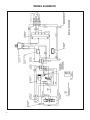
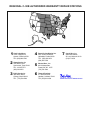
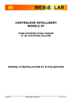
Service & Parts Manual
C-90B Electronic Air Cleaner
C90B-Svc (3-06)
TABLE OF CONTENTS
Friedrich Electronic Air Cleaner .................................................................................................................................... 2
Specifications ................................................................................................................................................................ 2
CAUTION - Before Operation........................................................................................................................................ 4
Operating Your Friedrich Air Cleaner ............................................................................................................................ 4
How Electronic Air Cleaners Work ................................................................................................................................ 5
Cleaning
Important Precautions ...................................................................................................................................... 5
Cleaning the Pre-Filter ..................................................................................................................................... 5
Cleaning the Carbon Filter ............................................................................................................................... 5
Cleaning the Electronic Cell ............................................................................................................................. 6
Alternate Cell Cleaning Method........................................................................................................................ 6
Discoloration of the Cell ................................................................................................................................................ 6
Replacing the Cell in Cabinet ........................................................................................................................................ 7
Activated Carbon Filter .................................................................................................................................................. 7
Consumer Troubleshooting Guide................................................................................................................................. 7
Troubleshooting Electronic Air Cleaner ......................................................................................................................... 8
Wiring Schematic .......................................................................................................................................................... 9
Major Components ........................................................................................................................................................ 10
C-90B Electronic Air Cleaner Component Parts List .................................................................................................... 11
Authorized Warranty Repair Stations ............................................................................................................................ 12
FRIEDRICH C-90B ELECTRONIC AIR CLEANER
The Friedrich Electronic Air Cleaner is a self-contained
console model consisting of a high voltage DC power supply,
electronic cell, 3 speed fan, pre-filter and activated carbon
post-filter in a rugged plastic cabinet.
It is designed to remove dust, tobacco smoke, pollen, bacteria,
and other airborne contaminants from the air. In just minutes,
you will notice improvements in your indoor air quality as your
Friedrich air cleaner begins the job of removing the billions
of irritating microscopic particles from your home or office.
The activated carbon post-filter also helps eliminate many
objectionable indoor odors.
SPECIFICATIONS
OPERATING TEMPERATURES
DIMENSIONS
This air cleaner is intended for use at temperatures
normally found in conditioned, occupied spaces.
Cabinet
ELECTRICAL RATINGS
115 Volt, 60 Hertz.
INDICATOR LIGHT
Cell
Pre-Filter
Carbon Filter
Height
Width
Depth
19"
15"
21 1/2"
1
16"
12 /2"
15 7/8"
12 3/4"
7
15 /8"
4 1/2"
1
/4"
3
1
12 /4"
/4"
Located on the top access cover, next to 3-speed
switch. Indicates air cleaner operating properly.
INTERLOCK SWITCH
Interrupts supply power to unit when access cover
is opened or carbon filter is removed.
WEIGHT
35 lbs. shipping weight
30 lbs. net weight
2
NOMINAL CURRENT AND POWER CONSUMPTION
Power Supply
High Speed
120 Volt, 60 Hertz
CFM
Amps
Watts
390
.80
90
Medium Speed
280
.56
64
Low Speed
220
.41
47
CAUTION - READ BEFORE OPERATION
• Remove the plastic cover from the activated carbon filter
and install in unit.
• Make sure that the top cover and carbon air filter are
securely in place.
• Position the pre-filter at the rear of the unit (closest to the
electronic cell) and the carbon filter at the front (where air
comes out.)
• This unit is equipped with a grounded plug for your
protection against shock hazards and should be plugged
directly into a properly grounded receptacle.
• Make sure the electronic cell is properly placed in the
cabinet (airflow arrow on the end plate should be pointing
toward the fan).
• Electronic air cleaners should NOT be placed in any area
where potentially explosive gases or vapors exist, nor
should they be used in wet environments. These units
should be operated in air-conditioned environments
OPERATING YOUR FRIEDRICH AIR CLEANER
CONTROLS
All controls for the Friedrich electronic air cleaner are located
on the top of the unit and are accessible through an opening
in the top cover. The controls are OFF - HI -MED - LOW.
Plus, an indicator lamp shows when the cleaner is on and
operating normally.
LOCATION
The best location is a position closest to the concentration of
tobacco smoke or dust producing activities.
Generally, HIGH fan speed is used in extreme conditions for
rapid cleaning, such as after a party where there were many
smokers; or for large areas where HIGH fan is required to
circulate the clean air into all areas of the room. MEDIUM
and LOW settings are usually adequate to maintain a clean
air environment.
Position the unit so that the airflow around the intake and
discharge grilles is not blocked. For best results, do not
place the intake grille (rear) closer than 8" (18 cm) from a
wall. Provide a clear, unobstructed path for the discharge
air. The farther the discharge air travels, the greater the
effectiveness of the air cleaner. For greater comfort, position
the air cleaner so that the discharge air does not cause
uncomfortable drafts.
The indicator lamp may flicker on and off and is no cause for
alarm. Should the lamp completely fail to come on, review
"BEFORE OPERATION" and "TROUBLESHOOTING"
sections.
To use a room air cleaner most effectively in rooms that
share an open doorway or archway, position the unit near
the common opening and direct the airflow into the adjacent
room to promote good air circulation.
During the initial use, random "snapping" sounds may be
heard. This is normal and the unit may continue to make
these noises the first few days of operation. After the initial
break-in period, only an occasional "snap" will be heard,
indicating the unit is cleaning your air. NOTE: As the air
cleaner electronic cell becomes dirty, it will “snap”
more frequently. When this occurs, you should consider
washing the cell.
ECONOMICAL CLEAN AIR
The Friedrich electronic air cleaner costs no more to operate
than a standard household light bulb. The benefits from
clean air far outweigh the low operating costs of continuous
cleaning. Remember, the more you operate your electronic
air cleaner, the cleaner your air will be.
3
HOW ELECTRONIC AIR CLEANERS WORK
Electronic air cleaners are an extremely efficient, cost effective method of removing indoor air contaminants. Unlike standard
media that merely block relatively large particles, electronic air cleaners attract and hold particles so small that an electron
microscope is needed to see them.
1
The PRE-FILTER catches lint, hair and other large
particles, as room air is drawn in through the rear
grille by the powerful 3-SPEED FAN.
1
2
3
4
In the IONIZING SECTION of the ELECTRONIC
CELL, billions of microscopic particles, too small to
be caught by the pre-filter, become electronically
charged as they pass through a powerful electric
field.
COLLECTOR PLATES immediately attract and
hold these "charged" particles much like metal
filings are attracted to a powerful magnet. The
accumulated particles are permanently removed
from the air and cling to the metal plates until
washed off.
2 3
4
Pre-Filter
Ionizing
Section of
Electronic
Cell
Collector
Plates
Carbon
Filter
Finally, an ACTIVATED CARBON FILTER removes
most household odors and fumes as the clean air
is circulated back into the room.
CLEANING
IMPORTANT PRECAUTIONS
CLEANING THE PRE-FILTER
Turn off air cleaner before opening top cover to remove
electronic cell and pre-filter for cleaning. Always be careful
when handling the electronic cell. Sharp edges and wires
are capable of inflicting wounds. Care should also be taken
when cleaning because of extremely hot water and potentially
harmful effects of detergents on your skin.
Remove the pre-filter and shake out or brush off the
accumulated dust and lint. If this is not adequate, a vacuum
may be used or the pre-filter can be cleaned with a mixture
of water and an all-purpose alkaline detergent-based cleaner
to remove tobacco smoke and cooking grease stains. A
thorough rinsing is required after each cleaning.
The collector plates of the electronic cell and the pre-filter
can become extremely dirty. With an excessive amount of
contamination buildup on the collector plates and the pre-filter,
the electronic air filter's efficiency decreases. Also, as dirt
builds up on the ionizing wires, the charge process becomes
less efficient.
After cleaning, allow to dry completely and reinsert.
To prevent this loss of efficiency, the electronic cell and prefilter must be cleaned regularly. How often will depend on
actual usage. Cleaning will be more frequent if the air cleaner
is operated continuously or under severe conditions.
4
CLEANING THE CARBON FILTER
Occasionally, the carbon filter will need cleaning. Use a
stream of air or a vacuum to remove the dirt. THE CHEMICAL
AND ODOR ABSORPTION CAPABILITIES CAN NOT BE
RESTORED. When the carbon filter can no longer remove
odors from the air, it must be replaced (Friedrich part number
616-420-01). THE CARBON FILTER MUST BE IN PLACE
FOR THE AIR CLEANER TO OPERATE.
CLEANING (CONTINUTED)
CLEANING THE ELECTRONIC CELL
ALTERNATE CELL CLEANING METHOD
The simplest method of cleaning the electronic cell is to use an
automatic dishwasher. The dishwasher provides the correct
cycle of wash, rinse and dry. Water temperatures normally
found in dishwashers 150°F to 170°F will not harm the cell.
If an automatic dishwasher is not available or not of sufficient
size to accommodate the cell, a large container capable of
holding the electronic cell can be used.
1.
1.
After turning off the air cleaner, remove the cell and gently
place on dishwasher rack with airflow arrows pointing up.
In some dishwashers, it may be necessary to remove the
top rack. BE EXTREMELY CAREFUL WHEN PLACING
ON DISHWASHER RACK TO NOT DAMAGE IONIZER
WIRES OR BEND COLLECTOR PLATES.
2. Use any available household dishwasher detergent
recommended for use in your appliance and follow
manufacturer's instructions.
3. Not all dishwashers may be capable of holding the
electronic cell. Be sure to compare the internal size of
the dishwasher to the dimensions of the electronic cell:
16" high x 12 1/2" wide x 4 1/2" deep. All parts of the
dishwasher must be able to move freely.
4. Take care to avoid damaging the cell when removing
it from the dishwasher. GENTLY LIFT THE CELL
STRAIGHT UP TO PREVENT DAMAGE TO IONIZER
WIRES AND COLLECTOR PLATES.
5. The cell may be hot when removed from the dishwasher.
Allow to cool or wear protective gloves. Make sure that
all water is drained off when removing the cell from the
dishwasher.
Mix an alkaline detergent with hot water in a ratio of 4
oz. of detergent to 1 gal. of water. Water temperature
should be between 150°F and 170°F. Be careful to avoid
prolonged skin contact with solution and DO NOT splash
solution in the eyes.
2. Soak the cell in the solution for about 15 minutes. The
solution should be agitated in some way every 2 to 3
minutes by sloshing or stirring the solution.
3. Remove the cell from the cleaning solution and place in
a clean container of hot water 150°F to 170°F for rinsing
and let set for 10 minutes.
4. Remove the cell from the rinse water and allow to drain
and dry before using.
5. If there is any detergent residue remaining, rinse again,
since it may affect the efficiency of the air cleaner.
NOTE: The ionizer wires may become so dirty that an
occasional cleaning is recommended. With a damp cotton
ball, wipe the ionizer wires by placing the wire between finger
and thumb.
6. If dirt stains or detergent residue remain after washing,
it may be necessary to rewash the cell or switch
detergent.
DISCOLORATION OF THE CELL
Occasionally, after the cleaning process, the cell may seem
stained. If the stain is black or very dark, it is probably
detergent residue and should be rinsed off at once. If yellowing
appears, it is probably stain from tobacco or other smoke.
The yellowing does not affect air cleaning efficiency. Use an
ammonia based or butyl based detergent to clean tobacco
tar and other smoke residue from the collector plates.
5
REPLACING THE CELL IN CABINET
After the cell has been washed, check for broken ionizer wires
and bent collector plates. If broken wires are observed, return
unit to Authorized Warranty Station for wire replacement. If
bent collector plates are observed, carefully straighten with
a screwdriver or other flat object. BE CERTAIN THAT NO
TWO COLLECTOR PLATES ARE TOUCHING AS THIS
WILL CAUSE ARCING AND PREVENT THE AIR CLEANER
FROM OPERATING PROPERLY.
Remember that the electronic air cleaner has a cell key which
prevents the cell from being positioned incorrectly. If the cell
seems stuck when being inserted or the access cover will not
fit securely, check to be sure that the cell is being positioned
properly. If excessive force is used, the cell or air cleaner unit
could be damaged. Airflow arrows point toward fan motor.
If the cell is placed into the air cleaner while still damp, the
indicator light may not come on until the cell is dry, which would
normally take about two hours. If the cell is energized and
annoying snapping sounds occur, the cell should be removed
from the air cleaner and allowed to thoroughly dry.
ACTIVATED CARBON FILTER
The activated carbon filter should be replaced when it is no
longer effective in eliminating odors. The life of the carbon
filter will depend on the concentration of odors and fumes
in the air passing through the air cleaner. Under normal
circumstances, the carbon filter should last up to six months.
THE CARBON FILTER MUST BE IN PLACE FOR THE AIR
CLEANER TO OPERATE.
CONSUMER TROUBLESHOOTING GUIDE
In the event that you experience problems with the operation of your air cleaner, please...
• Make sure electronic cell is clean, dry and properly
installed.
• Check fan motor and indicator lamp on all speed settings
starting with low.
• Make sure pre-filter and carbon filter are both properly
installed.
If your air cleaner still has any of the following problems,
proceed step by step as shown below until no further action
should be taken.
• Make sure the top cover is properly snapped in place.
PROBLEM 1
PROBLEM 2
PROBLEM 3
FAN OFF
LAMP OFF
FAN ON
LAMP OFF
FAN OFF
LAMP ON
Make sure the supply cord is plugged
Check the electronic cell to see if any
of the collector plates are touching.
Gently straighten and evenly space
the plates.
This condition represents a failure of
the air cleaner. Return the unit to an
Authorized Warranty Station for repair.
See Page 12.
into a standard household receptacle.
Make sure there is voltage to the receptacle by testing with another electric
device.
Make sure the carbon filter is in place.
Make sure the top access cover is
properly in place in order to actuate the
interlock switch. The interlock switch is
provided for consumer safety and should
never be bypassed.
No further corrective actions should be
taken by the consumer. Return the unit
to an Authorized Warranty Station for
repair. See Page 12.
6
Check the electronic cell to see if any
of the ionizer wires are broken. See
Major Components for their location. If
broken wires are observed, no further
corrective actions should be taken by
the consumer. Return the unit to an
Authorized Warranty Station for repair.
See Page 12.
TROUBLESHOOTING ELECTRONIC AIR CLEANER
Electrical Troubleshooting Procedure for Electronic Air Cleaner
TO USE THIS CHART:
1.
Follow the steps in order. Don't skip around.
2.
Each time you isolate and fix a problem, go back to
START.
3.
Repeat ALL the steps until the air cleaner checks out OK
START
Make sure electronic cell is clean,
dry and properly
installed
WARNING
Some of these steps expose dangerous high
voltage. Only a qualified service technician
should attempt this procedure.
Make sure pre-filter and activated carbon filter are properly
installed, and carbon filter is
activating filter interlocking
switch lever.
Replace the access
cover and turn the air
cleaner on. Check Low,
then Med, then Hi on
multispeed fan.
Both
Off
Check fan and
neon light.
Both
Off
Light
On
Fan
On
Push interlock
switch with plastic
handled screwArcing
driver. Short from
No
cell frame to a hot
collector plate.
Arcing
Yes
Electronic
Air Cleaner is
OK.
Check Line 120
VAC power. Correct as needed.
Fan
On
Jumper fan
switch contacts
- For each speed
in turn on multispeed fans.
Remove cell.
Replace access
cover, Check
neon light.
Light
Off
Check filter Interlocking Switch,
Access Cover
Interlocking
Switch, System
Switch.
120 VAC Present
Replace Switch
Fan
Off
Turn OFF power. Make
sure shaft on fan motor
rotates freely. Check for
open windings. Replace if
necessary.
Lamp
On
Fan
Off
Replace System Switch or
fan motor.
Lamp
Off
Fan
On
Remove access
Voltage Light OK, replace
Check 100 VDC
Light
Voltage
cover. Check
complete power
voltage
across
Below
Off
for correct input correct
supply
70
VDC
terminal on lamp.
voltage: 120 VAC.
Models P1 and P2
Voltage above 120 VDC
terminals on
power supply.
Voltage NOT
Replace Light
Correct
Inspect cell for
- Bent Collector Plates
- Broken Ionizer Wires Cell
- Dirt on Insulators
Damaged
- Damaged or dirty
Contact Tabs
Repair or
replace cell
Check wiring back
through switch, power
cord, and outlet to circuit breaker or fuse.
No cell damage noted
With Ohmmeter, check
for short between
- Cell Frame and Ionizer
Section
- Cell frame and Collector Section
Cell
Shorted
Replace Cell
Infinite
Resistance
Cell OK
Check Contact Board for
coating on ground contacts
Dirty
Clean contacts with fine
grain sandpaper or emery
cloth.
Clean
WARNING
Electronic components on power supply
board are not field replaceable. Attempted service will damage the board.
Check wire connections
are secured properly
OK
Replace Power Board
Assembly
7
C-90B ELECTRONIC AIR CLEANER COMPONENT PARTS LISTING
PART NO.
616-203-01
616-420-01
616-424-05
616-425-00
920-010-01
616-209-01
616-211-01
616-212-01
906-081-00
616-210-01
906-080-00
917-018-00
605-420-10
616-217-00
616-410-00
619-893-02
906-022-08
906-051-00
906-051-00
605-000-96
610-714-74
616-201-02
616-202-01
616-207-00
616-215-00
616-219-00
616-220-00
616-224-00
616-224-01
616-224-02
616-224-03
616-224-04
616-225-00
616-402-00
616-977-00
616-421-06
619-980-00
616-213-00
616-556-00
616-204-00
616-931-00
250-346-01
8
DESCRIPTION
QTY.
FILTER, PRE ............................................................................................................. 1
FILTER, CARBON ..................................................................................................... 1
CARTON, RSC .......................................................................................................... 1
PACKING, TOP & BOTTOM ...................................................................................... 2
OWNERS MANUAL C-90B ....................................................................................... 1
BUTTON, SYSTEM SWITCH .................................................................................... 4
SIDE, CABINET ......................................................................................................... 2
LID, CABINET ........................................................................................................... 1
SCREW, #4 - 24 X 3/4".............................................................................................. 2
BASE, CABINET ....................................................................................................... 1
SCREW .................................................................................................................... 10
STRAIN, RELIEF ....................................................................................................... 1
FAN, 6 BLADE ........................................................................................................... 1
ORIFICE .................................................................................................................... 1
BLADE COVER ASSEMBLY ..................................................................................... 1
PANEL, CONTROL.................................................................................................... 1
SCREW, SELF-TAPPING .......................................................................................... 2
SCREW, TAPPING 8A X 3/8 H/W SER ZP ............................................................... 5
SCREW, T/C 8-32 X 3/8 H/W SER ZP ...................................................................... 5
SUPPLY CORD ......................................................................................................... 1
MOTOR ..................................................................................................................... 1
POWER SUPPLY ...................................................................................................... 1
CONTACT BOARD .................................................................................................... 1
SWITCH, SYSTEM .................................................................................................... 1
SPRING, CELL GROUND ......................................................................................... 1
SWITCH, INTERLOCK .............................................................................................. 1
LIGHT INDICATOR .................................................................................................... 1
WIRE ......................................................................................................................... 1
WIRE ......................................................................................................................... 1
WIRE ......................................................................................................................... 1
WIRE ......................................................................................................................... 1
WIRE ......................................................................................................................... 1
PLUG ASSEMBLY ..................................................................................................... 1
CAP ASSEMBLY ....................................................................................................... 1
TWIST LOK STANDOFF ........................................................................................... 3
BRACKET, GRILLE ASSEMBLY ............................................................................... 2
RIVET, ALUMINUM .................................................................................................. 10
IONIZER/COLLECTOR CELL ................................................................................... 1
IONIZER WIRE .......................................................................................................... 9
SWITCH, FILTER INTERLOCK ................................................................................. 1
BRACKET, MOTOR MOUNT..................................................................................... 1
LID STRIKER ............................................................................................................ 2
MAJOR COMPONENTS
9
WIRING SCHEMATIC
10
REGIONAL C-90B AUTHORIZED WARRANTY REPAIR STATIONS
7
6
Appliance
1 Cagle's
114 S. Campus Ave.
4
Ontario, California 91761
TEL: (909) 986-9789
Service Co.
2 Alamo
1450 North Flores
San Antonio, Texas 78212
TEL: 210/227-7571
(800) 328-2450
& G Service Co.
3 B3950
North Elston
Chicago, Illinois 60618
TEL: (773) 588-2290
Reeve Air Conditioning, Inc.
2501 South Park Road
Hallandale, Florida 33009
TEL: (954) 962-0252
(800) 962-3383
5
Weston Bros., Inc.
99-16 Metropolitan
Forest Hills, NY 11375
(718) 793-2000
6
Thermal Products
271 Plauche Street
Harahan, Louisiana 70123
TEL: (506) 818-1008
Serv. Inc.
7 Carroll
4000 Shenandoah
St. Louis, Missouri 63110
(314) 371-3033
Friedrich Air Conditioning Company
P.O. Box 1540
San Antonio, TX 78295
210.357.4400
www.friedrich.com
ELECTRONIC AIR CLEANER
LIMITED WARRANTY
Friedrich Air Conditioning Company warrants its electronic air cleaner to be free from defects in workmanship or materials, under
normal use and service, for a period of One Year from the date of purchase by the original owner. If at any time during the warranty
period, the product is found to be defective or malfunctions, Friedrich Air Conditioning Company will repair or replace the defective
part (at its option) and provide the shop labor to repair this electronic air cleaner.
This warranty shall not apply if it is shown by FRIEDRICH that the defect or malfunction was caused by neglect or abuse during
operation by consumer.
The cost of shipping the unit to Friedrich Air Conditioning Company or a service agency shall be covered by the purchaser. The
repaired or replaced part or unit will be shipped by Friedrich Air Conditioning Company to the purchaser, freight prepaid. The
warranty on any repaired or replacement part shall be for a duration of time no longer than the remaining or unexpired term of the
original warranty.
This warranty does not cover any other charges incurred by the purchaser.
The sole responsibility of FRIEDRICH shall be to repair the product within the terms stated above. FRIEDRICH SHALL NOT BE
LIABLE FOR ANY CONSEQUENTIAL DAMAGES RESULTING FROM ANY BREACH OF WARRANTY, EXPRESS OR IMPLIED,
APPLICABLE TO THIS PRODUCT. Some states do not allow the exclusion or limitation of consequential damages, so this
limitation may not apply to you.
THIS WARRANTY IS IN LIEU OF ALL OTHER WARRANTIES, EXPRESSED OR IMPLIED, AND THE WARRANTIES OF
MERCHANTABILITY AND FITNESS FOR A PARTICULAR PURPOSE ARE HEREBY EXCLUDED BEYOND THE ONE YEAR
DURATION OF THIS WARRANTY. Some states do not allow limitations on how long an implied warranty lasts, so the above
limitation may not apply to you.
This warranty gives you specific legal rights, and you may also have other rights which can vary from state to state.
(10-04)
FRIEDRICH AIR CONDITIONING CO.
Post Office Box 1540 · San Antonio, Texas 78295-1540
4200 N. Pan Am Expressway · San Antonio, Texas 78218-5212
(210) 357-4400 · FAX (210) 357-4480
www.friedrich.com
Printed in the U.S.A.
C90B-Svc (3-06)