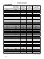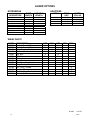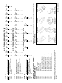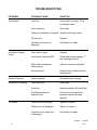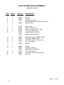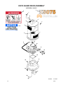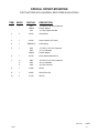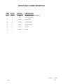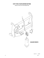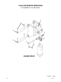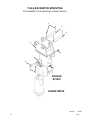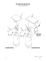
1
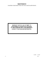
OPERATOR’S AND PARTS
MANUAL
X4075 / X5075
HIGH TORQUE AUGER DRIVES
SERIAL NUMBER: ___________________
MODEL NUMBER: ___________________
800-456-7100 I www.paladinlcg.com
Manual Number: OM701
Part Number: 75601
Rev. 503 Gay Street, Delhi, IA 52223, United States of America
M-1607
1-25-10-2
TABLE OF CONTENTS
X4075 & X5075 AUGER DRIVES
PREFACE...........................................................................................................................................................3
SAFETY PRECAUTIONS
SAFETY STATEMENTS............................................................................................................................ 5
GENERAL SAFETY PRECAUTIONS.....................................................................................................5-7
EQUIPMENT SAFETY PRECAUTIONS................................................................................................... 8
INSTALLATION........................................................................................................................................... 9-11
HYDRAULIC SYSTEM HOOK-UP INSTRUCTIONS.......................................................................... 12
OPERATING INSTRUCTIONS.................................................................................................................. 13
maintenance
lubrication......................................................................................................................................... 14
DAILY INSPECTION............................................................................................................................... 14
PLANETARY GEARBOX......................................................................................................................... 15
STORAGE PROCEDURE....................................................................................................................... 15
PLANETARY GEAR REDUCTION SERVICE PARTS............................................................................. 16
OPTIONS
AUGER OPTIONS..............................................................................................................................17-18
AUGER WEAR PARTS......................................................................................................................18-19
TROUBLESHOOTING................................................................................................................................. 20
specifications......................................................................................................................................... 21
limited warranty.................................................................................................................................. 23
PARTS
X4075 AUGER DRIVE ASSEMBLY....................................................................................................24-25
X5075 AUGER DRIVE ASSEMBLY....................................................................................................26-27
stANDARD MOUNTING KITS
UNIVERSAL SWIVEL KIT..................................................................................................................30-31
SKID STEER LOADER MOUNTING..................................................................................................32-33
TRACTOR LOADER MOUNTING - JOHN DEERE LOADERS.........................................................34-35
SPECIAL OFFSET MOUNTING.........................................................................................................36-37
FRONT END LOADER MOUNTING..................................................................................................38-39
QCP 700 COUPLER MOUNTING......................................................................................................40-41
DIPPER MOUNTING - PENDULUM STYLE......................................................................................42-47
BRADCO BACKHOE DIPPER MOUNTING.......................................................................................48-49
MINI EXCAVATOR & SMALL BACKHOE MOUNTING......................................................................50-51
TLB & EXCAVATOR MOUNTING - QUICK HITCH COUPLER STYLE.............................................52-53
EXCAVATOR MOUNTING - QUICK ATTACH STYLE........................................................................54-55
TLB & EXCAVATOR - PIN GRABBER/PIN ON STYLE - PIVOT MOUNTING...................................56-57
TLB & EXCAVATOR - PIN GRABBER/PIN ON STYLE - CRADLE READY MOUNTING..................58-59
EXCAVATOR WELD ON MOUNTING................................................................................................60-61
WHEEL LOADER MOUNTING..........................................................................................................62-65
TELEHANDLER MOUNTING.............................................................................................................66-67
M-1734
75601
11-28-07
1
THIS PAGE
IS INTENTIONALLY
BLANK
2
75601
PREFACE
GENERAL COMMENTS
Congratulations on the purchase of your new McMillen product! This product was carefully designed and manufactured to give you many years of dependable service. Only minor
maintenance (such as cleaning and lubricating) is required to keep it in top working condition.
Be sure to observe all maintenance procedures and safety precautions in this manual and on
any safety decals located on the product and on any equipment on which the attachment is
mounted.
This manual has been designed to help you do a better, safer job. Read this manual
carefully and become familiar with its contents. WARNING! Never let anyone operate this unit without reading the "Safety Precautions"
and "Operating Instructions" sections of this manual.
Always choose hard, level ground to park the vehicle on and set the brake
so the unit cannot roll.
Unless noted otherwise, right and left sides are determined from the operator’s control
position when facing the attachment.
NOTE: The illustrations and data used in this manual were current (according to the
information available to us) at the time of printing, however, we reserve the right to redesign and change the attachment as may be necessary without notification.
BEFORE OPERATION
The primary responsibility for safety with this equipment falls to the operator. Make
sure the equipment is operated only by trained individuals that have read and understand this
manual. If there is any portion of this manual or function you do not understand, contact your
local authorized dealer or the manufacturer.
SAFETY ALERT SYMBOL
This is the "Safety Alert Symbol" used by this industry. This symbol is used to
warn of possible injury. Be sure to read all warnings carefully. They are included
for your safety and for the safety of others working with you.
SERVICE
When servicing your product, remember to use only manufacturer replacement parts. Substitute parts may not meet the standards required for safe, dependable operation.
To facilitate parts ordering, record the model and serial number of your unit in the space
provided on the cover of this manual. This information may be obtained from the identification
plate located on the product.
The parts department needs this information to insure that you receive the correct parts
for your specific model.
M-1643 10-18-07
75601
3
THIS PAGE
IS INTENTIONALLY
BLANK
4
75601
SAFETY STATEMENTS
THIS SYMBOL BY ITSELF OR WITH A WARNING WORD THROUGHOUT THIS MANUAL IS USED TO CALL YOUR ATTENTION TO INSTRUCTIONS INVOLVING YOUR
PERSONAL SAFETY OR THE SAFETY OF OTHERS. FAILURE TO FOLLOW THESE
INSTRUCTIONS CAN RESULT IN INJURY OR DEATH.
DANGER
THIS SIGNAL WORD IS USED WHERE SERIOUS INJURY OR DEATH
WILL RESULT IF THE INSTRUCTIONS ARE NOT FOLLOWED PROPERLY.
WARNING
THIS SIGNAL WORD IS USED WHERE SERIOUS INJURY OR DEATH
COULD RESULT IF THE INSTRUCTIONS ARE NOT FOLLOWED PROPERLY.
CAUTION
THIS SIGNAL WORD IS USED WHERE MINOR INJURY COULD RESULT IF
THE INSTRUCTIONS ARE NOT FOLLOWED PROPERLY.
NOTICE
NOTICE INDICATES A PROPERTY DAMAGE MESSAGE.
GENERAL SAFETY PRECAUTIONS
WARNING!
READ MANUAL PRIOR TO INSTALLATION
Improper installation, operation, or maintenance of this equipment could result in serious injury or death. Operators and maintenance personnel should read this manual,
as well as all manuals related to this equipment and the prime mover thoroughly
before beginning installation, operation, or maintenance. FOLLOW ALL SAFETY
INSTRUCTIONS IN THIS MANUAL AND THE PRIME MOVER’S MANUAL(S).
READ AND UNDERSTAND ALL SAFETY STATEMENTS
Read all safety decals and safety statements in all manuals prior to operating or
working on this equipment. Know and obey all OSHA regulations, local laws, and
other professional guidelines for your operation. Know and follow good work practices when assembling, maintaining, repairing, mounting, removing, or operating this
equipment.
KNOW YOUR EQUIPMENT
Know your equipment’s capabilities, dimensions, and operations before operating.
Visually inspect your equipment before you start, and never operate equipment that
is not in proper working order with all safety devices intact. Check all hardware to
ensure it is tight. Make certain that all locking pins, latches, and connection devices
are properly installed and secured. Remove and replace any damaged, fatigued, or
excessively worn parts. Make certain all safety decals are in place and are legible.
Keep decals clean, and replace them if they become worn or hard to read.
M-806
75601
7-28-05-2
5
GENERAL SAFETY PRECAUTIONS
WARNING!
PROTECT AGAINST FLYING DEBRIS
Always wear proper safety glasses, goggles, or a face shield when driving pins in or
out, or when any operation causes dust, flying debris, or any other hazardous material.
WARNING!
LOWER OR SUPPORT RAISED EQUIPMENT
Do not work under raised booms without supporting them. Do not use support material made of concrete blocks, logs, buckets, barrels, or any other material that could
suddenly collapse or shift positions. Make sure support material is solid, not decayed, warped, twisted, or tapered. Lower booms to ground level or on blocks. Lower
booms and attachments to the ground before leaving the cab or operator’s station.
WARNING!
USE CARE WITH HYDRAULIC FLUID PRESSURE
Hydraulic fluid under pressure can penetrate the skin and cause serious injury or
death. Hydraulic leaks under pressure may not be visible. Before connecting or disconnecting hydraulic hoses, read your prime mover’s operator’s manual for detailed
instructions on connecting and disconnecting hydraulic hoses or fittings.
•
•
•
Keep unprotected body parts, such as face, eyes, and arms as far away as
possible from a suspected leak. Flesh injected with hydraulic fluid may develop
gangrene or other permanent disabilities.
If injured by injected fluid, see a doctor at once. If your doctor is not familiar with
this type of injury, ask him or her to research it immediately to determine proper
treatment.
Wear safety glasses, protective clothing, and use a piece of cardboard or wood
when searching for hydraulic leaks. DO NOT USE YOUR HANDS! SEE ILLUSTRATION.
CARDBOARD
HYDRAULIC HOSE
OR FITTING
MAGNIFYING GLASS
M-807 7-28-05-2
6
75601
GENERAL SAFETY PRECAUTIONS
WARNING!
DO NOT MODIFY MACHINE OR ATTACHMENTS
Modifications may weaken the integrity of the attachment and may impair the function, safety, life, and performance of the attachment. When making repairs, use only
the manufacturer’s genuine parts, following authorized instructions. Other parts may
be substandard in fit and quality. Never modify any ROPS (Roll Over Protection
Structure) or FOPS (Falling Object Protective Structure) equipment or device. Any
modifications must be authorized in writing by the manufacturer.
WARNING!
SAFELY MAINTAIN AND REPAIR EQUIPMENT
•
•
•
•
•
Do not wear loose clothing or any accessories that can catch in moving parts. If
you have long hair, cover or secure it so that it does not become entangled in the
equipment.
Work on a level surface in a well-lit area.
Use properly grounded electrical outlets and tools.
Use the correct tools for the job at hand. Make sure they are in good condition for
the task required.
Wear the protective equipment specified by the tool manufacturer.
SAFELY OPERATE EQUIPMENT
Do not operate equipment until you are completely trained by a qualified operator
in how to use the controls, know its capabilities, dimensions, and all safety requirements. See your machine’s manual for these instructions.
• Keep all step plates, grab bars, pedals, and controls free of dirt, grease, debris,
and oil.
• Never allow anyone to be around the equipment when it is operating.
• Do not allow riders on the attachment or the prime mover.
• Do not operate the equipment from anywhere other than the correct operator’s
position.
• Never leave equipment unattended with the engine running, or with this attachment in a raised position.
• Do not alter or remove any safety feature from the prime mover or this attachment.
• Know your work site safety rules as well as traffic rules and flow. When in doubt
on any safety issue, contact your supervisor or safety coordinator for an explanation.
M-808 7-28-05-2
75601
7
EQUIPMENT SAFETY PRECAUTIONS
WARNING! KNOW WHERE UTILITIES ARE
Observe overhead electrical and other utility lines. Be sure equipment will clear them.
When digging, call your local utilities for location of buried utility lines, gas, water, and
sewer, as well as any other hazard you may encounter.
OPERATING THE PRIME MOVER
Avoid steep hillside operation, which could cause the prime mover to overturn. Consult
your prime mover operator’s and safety manuals for maximum incline allowable.
EXPOSURE TO RESPIRABLE CRYSTALLINE SILICA DUST ALONG
WITH OTHER HAZARDOUS DUSTS MAY CAUSE SERIOUS OR
FATAL RESPIRATORY DISEASE.
It is recommended to use dust suppression, dust collection and if necessary, personal
protective equipment during the operation of any attachment that may cause high levels
of dust.
WORKING WITH THE AUGER
• All bystanders should be kept a minimum of 10 feet (3 meters) away from the working
area of the earth auger.
• An operator must not use drugs or alcohol, which can change his or her alertness or
coordination. An operator taking prescription or over-the-counter drugs should seek
medical advice on whether or not he or she can safely operate equipment.
• Before exiting the prime mover, lower the earth auger to the ground, turn off the prime
mover’s engine, and lock the prime mover’s brakes.
• Flow and pressure gauges, fittings, and hoses must have a continuous operating pressure rating of at least 25% higher than highest pressures of the system.
TRANSPORTING THE AUGER
• Travel only with the earth auger in a safe transport position to prevent uncontrolled
movement. Drive slowly over rough ground and on slopes.
• Tether the earth auger with a chain, if necessary, to prevent uncontrolled swinging of
the auger when moving from hole to hole.
• Remove the earth auger from the prime mover before transporting to and from the job
site.
MAINTAINING THE AUGER
• Never adjust a relief valve for pressure higher than recommended by the prime mover
manufacturer.
• Never perform any work on an earth auger unless you are authorized and qualified to
do so. Always read the operator service manual(s) before any repair is made. After
completing maintenance or repair, check for correct functioning of the earth auger. If
not functioning properly, always tag “DO NOT OPERATE” until all problems are corrected.
• Worn, damaged, or illegible safety decals must be replaced. New safety decals can be
ordered from McMillen®.
M-809 9-17-07-2
8
75601
INSTALLATION INSTRUCTIONS
GENERAL INFORMATION
Find the mounting kit diagram and parts list for the kit you have received. Study the
diagram and familiarize yourself with the names of the various parts. This knowledge will assist
you in understanding these instructions.
Read these instructions carefully before attempting to mount the auger.
READ AND UNDERSTAND ALL SAFETY INFORMATION PRIOR TO
MOUNTING YOUR AUGER.
QUICK ATTACH MOUNTING ASSEMBLIES
(Includes some Excavator Mounts, Telehandler Mounts and all Skid Steer & Wheel Loader Mounts.)
1.
Remove the bucket or other attachment from the prime mover quick attach mechanism.
2.
Attach the quick attach mounting bracket to the prime mover quick attach mechanism,
as per manufacturer’s recommendations.
3.
Attach the swivel (#21694) to the quick attach mounting bracket with pin (#22255) provided. Secure the pin in place with klik pins (#21169).
4.
If your mounting bracket is designed for the installation of a cradle, bolt the cradle to the
bracket using the .50” UNC X 2.00” capscrews, lock washers and hex nuts provided.
5.
Install the drive unit to the swivel using the pin provided with the drive unit assembly.
6.
Install the auger to the drive unit with the bolt and nut provided with the drive unit assembly.
7.
Refer to the “HYDRAULIC SYSTEM HOOK-UP” section in this manual for hydraulic
connection instructions and recommendations.
BACKHOE AND EXCAVATOR “PENDULUM” MOUNTING ASSEMBLIES
1.
Remove the bucket from the dipper arm and curl cylinder pin connections. The dipper
arm pin will be used to attach auger pendulum mounting to the dipper arm. Curl cylinder
pin will not be required for auger installation.
2.
If using a universal adjustable width pendulum mounting assembly: Space the two backhoe adapter ears to the same width as the dipper arm and secure to the base using the
.50” hardware provided. After determining the correct width, the backhoe adapter ears
must be welded to the base.
M-1650
75601
10-22-07
9
INSTALLATION INSTRUCTIONS
3.
Attach the pendulum mounting (all types) to the dipper using the dipper arm pin removed from the bucket in Step #1. Secure the bucket pin as per prime mover manufacturer’s recommendation.
4.
Install the auger drive unit to pendulum mount with pivot pin provided with the drive unit
assembly.
5.
Install the auger to the drive unit with the bolt and nut provided with the drive unit assembly.
6.
Refer to the “HYDRAULIC SYSTEM HOOK-UP” section in this manual for hydraulic
connection instructions and recommendations.
BACKHOE AND EXCAVATOR “PIN GRABBER” MOUNTING ASSEMBLIES
1.
Remove the bucket from the dipper arm and curl cylinder pin connections.
2.
Attach the pin grabber mounting (all types) to the dipper and curl cylinder using the pivot
pins and cotter pins provided.
3.
Attach the swivel (#21694) to the pin grabber mounting bracket with pivot pin provided.
Secure the pin in place with klik pins (#21169).
NOTE: Some assemblies require the installation of step bushings on each side of the
swivel when supplied with a pivot pin longer than the standard #22255 (1.25” diameter
by 6.00” effective length) pivot pin.
4.
If your mounting bracket is designed for the installation of a cradle, bolt the cradle to the
bracket using the .50” UNC X 2.00” capscrews, lock washers and hex nuts provided.
5.
Install the drive unit to the swivel using the pin provided with the drive unit assembly.
6.
Install the auger to the drive unit with the bolt and nut provided with the drive unit assembly.
7.
Refer to the “HYDRAULIC SYSTEM HOOK-UP” section in this manual for hydraulic
connection instructions and recommendations.
M-1651
10
10-22-07
75601
INSTALLATION INSTRUCTIONS
UNIVERSAL FRONT END LOADER MOUNTING ASSEMBLY
1
The universal front end loader mounting assembly (#21235) can be used to adapt your
McMillen Earth Auger to the side of the loader arm, lip of a bucket, or fork lift forks. DO
NOT USE ON SKID -STEER LOADERS.
2.
Place loader bracket clamp plate (#21449) on the inside of the loader arm, top of the
bucket lip or top of fork lift fork.
NOTE: For mounting on lip of bucket you will need to drill two 7/16” diameter holes
through the bucket.
3.
Place the loader bracket #21628 on the opposite side of clamp plate and secure with
the four .44” bolts #1080 and hex nuts #1227 provided.
4.
Attach the swivel (#21694) to the loader mounting bracket with pivot pin #22255 provided. Secure the pin in place with klik pins (#21169).
5.
Install the drive unit to the swivel using the pin provided with the drive unit assembly.
6.
Install the auger to the drive unit with the bolt and nut provided with the drive unit assembly.
7.
Refer to the “HYDRAULIC SYSTEM HOOK-UP” section in this manual for hydraulic
connection instructions and recommendations.
WELD-ON EXCAVATOR MOUNTING
McMillen offers a blank weld on plate with mounting ears and swivel for welding onto
your own excavator mounting bracket.
After securely welding the plate onto your bracket:
1.
Attach the swivel (#21694) to the mounting plate with pivot pin #22255 provided. Secure
the pin in place with klik pins #21169.
2.
Install the drive unit to the swivel using the pin provided with the drive unit assembly.
3.
Install the auger to the drive unit with the bolt and nut provided with the drive unit assembly.
4.
Refer to the “HYDRAULIC SYSTEM HOOK-UP” section in this manual for hydraulic
connection instructions and recommendations.
M-1652
75601
10-22-07
11
HYDRAULIC SYSTEM HOOK-UP INSTRUCTIONS
GENERAL INFORMATION
Once the installation instructions are complete, you are now ready to make the hydraulic connections necessary to operate your earth drill.
READ AND UNDERSTAND SAFETY INFORMATION PRIOR TO
MAKING HYDRAULIC CONNECTIONS.
Your equipment dealer is in the best position to advise you as to where the best place
on your machine is to make the hydraulic connections to power your earth drill drive unit. The
list below shows the most common places to “tap” into the hydraulic system on various types
of machines.
• SKID STEER LOADERS - Auxiliary hydraulic outlets.
• BACKHOES & EXCAVATORS - Auxiliary hydraulic outlets or bucket curl cylinder circuit.
• WHEEL LOADERS & TRACTOR LOADERS - Auxiliary hydraulic outlets or bucket tilt
(dump) cylinder circuit.
Determine the length of hydraulic hoses required to plumb drive unit into the place on
your machine where you will be “tapping” into the hydraulics. Be sure the two hydraulic hoses
are long enough to perform at the full range of the earth drill’s operating capacity. A case drain
line will also be required to operate your earth drill.
• Models X4075, X5075, X6075, X8075 & 8K2 - These models require two 3/4” (19mm) ID
hydraulic hoses, with #12 JIC Female fittings on one end of each hose, to connect hoses to
drive unit fittings. A case drain line is also required. The skid steer hydraulic kits for the high
torque auger drives include a case drain line. A universal excavator Drain Line Kit #21218 is
available through your local dealer.
NOTE: Fittings on the other end of each hydraulic hose should match the threads on the hydraulic quick couplers to be used.
WARNING! HOSES AND FITTINGS MUST HAVE A CONTINUOUS OPERATING PRESSURE RATING OF AT LEAST 25% HIGHER THAN THE HIGHEST PRESSURES OF THE SYSTEM YOU ARE “TAPPING” INTO.
Once all of the hydraulic connections have been made and checked for leaks, you are
now ready to operate your earth drill. READ AND UNDERSTAND OPERATING INSTRUCTIONS AND SAFETY INFORMATION PRIOR TO OPERATING YOUR EARTH DRILL.
M-1653
12
10-22-07
75601
OPERATING INSTRUCTIONS
1.
After all installation instructions have been completed, safety information read and understood,
and the rest of this operator’s manual has been reviewed, your McMillen Hydraulic Earth Drill is
now ready for use.
2.
With the auger raised off the ground and the vehicle engine set at a low RPM, activate the earth
drill control valve to determine which position the control valve lever must be in to turn auger in
a forward (clockwise) rotation. This is the “digging” position.
3.
Before beginning to dig, experiment with auger speed to determine a suitable auger RPM. Generally in light and sandy soil a high RPM is desirable. In hard, rocky, or frozen soils a slower
RPM is desirable. To increase auger RPM, increase vehicle engine RPM. To decrease auger
RPM, decrease vehicle engine RPM.
4.
Return earth drill control valve to neutral position to stop the auger. Lower the auger to the
ground so that only the center point penetrates the ground about 2” (51mm).
5.
Activate the earth drill control valve so auger is turning in a forward (clockwise) rotation. Use
only enough down pressure to assure positive penetration of auger into the ground. Ease up on
down pressure if auger rotation slows down drastically or stalls.
NOTE: Excessive down pressure will cause the auger to stall frequently.
6.
When auger has penetrated the ground about 24” (610mm), raise the auger from the hole to
clean the dirt out. Repeat this procedure until the desired hole depth is obtained.
7.
Once the required hole depth is reached, allow the auger to turn a few seconds at this depth to
clean the hole.
8.
Return the earth drill control valve to the neutral position to stop the rotation of the auger. Raise
the auger out of the hole, move away from the hole, then activate the earth drill control valve to
spin the loose soil off of the augers.
NOTE: Do not reverse the auger rotation to remove from the hole as loose soil on the auger
flights will fall back into the hole.
9.
If necessary, repeat steps 7 & 8 to obtain a cleaner hole.
10.
In some soil conditions or when excessive down pressure is applied, auger may “screw” itself
into the ground and become stuck causing earth drill to stall. If this happens, reverse the auger
rotation (counter-clockwise) by moving the control valve lever to the reverse position and slowly
raise the auger. Once unstuck, return the control valve lever to the forward rotation position and
continue digging.
11.
If the auger becomes lodged under rocks, roots, or other large obstructions, do not attempt to
raise the auger out of the ground. See step 10 for proper procedure to relieve the auger.
12.
Avoid excessive side loading to earth drill which can cause drive unit or auger damage.
13.
Keep auger teeth and points in good condition. Check frequently and always keep spares on
hand so they can be replaced as wear is detected to avoid damage to tooth holders and auger
flighting.
WARNING: To prevent possible injury or death, keep all bystanders 10 feet or more
away from rotating auger. Take extra precautions when digging in locations
where any type of landscape fabric may be present.
M-1656
75601
11-12-07
13
MAINTENANCE
GENERAL INFORMATION
Your McMillen earth drill was designed to be virtually maintenance free. Very little effort
is needed to keep it in top working condition. It is however, important to follow these procedures to get full performance and longevity out of the unit.
LUBRICATION
Change planetary gear reduction oil with API-GL-5, 80W or 90W lubricant after the first
50 hours of operation and then every 1000 hours or 12 months, whichever comes first.
DAILY INSPECTION
•
•
•
•
•
•
•
•
•
•
•
Check hydraulic oil for cleanliness and contamination. Change if necessary.
Check hydraulic hoses for damage, leaking and/or signed of excessive heat. Replace if
necessary.
Check auger point for excessive wear or loose fit. Replace if necessary.
Check auger teeth for excessive wear or loose fit. Replace if necessary.
Check output shaft for excessive wear, damage or leakage. Replace if necessary.
Check all bolts and pivot pins for damage, breaks or wear. Replace if necessary.
CAUTION! EXCESSIVE VENTING OF LUBRICANT FROM PLANETARY MAY INDICATE
THAT THE MOTOR SHAFT SEAL IS LEAKING. UNIT SHOULD BE REPAIRED
IMMEDIATELY.
PLANETARY SHAFT SEAL REPLACEMENT IS THE ONLY PLANETARY REPAIR THAT
CAN BE MADE WHILE THE UNIT IS UNDER WARRANTY. (SEE PARTS PAGES FOR
PLANETARY SEAL NUMBER.)
MOTOR SHAFT SEAL REPLACEMENT IS THE ONLY HYDRAULIC MOTOR REPAIR THAT
CAN BE MADE WHILE THE UNIT IS UNDER WARRANTY. (SEE PARTS PAGES FOR MOTOR SEAL NUMBER.)
M-1727
14
11-14-07
75601
MAINTENANCE
PLANETARY GEARBOX
Change gear box oil using API-GL-5, 80W or 90W lubricant after the first 50 hours of
operation and then every 1200 hours or 12 months, whichever comes first. Check oil level frequently to maintain proper lubrication.
CHECKING PLANETARY LUBRICANT
1.
Place the planetary in a horizontal position.
2.
Remove fill plug.
3.
Check the lubricant level. Gear lub level should be visible through the fill plug hole.
4.
To Fill: Tilt the planetary slightly (maximum 15°) and add lubricant up to fill plug location.
With the planetary in this position , lubricant should cover the internal gear and be visible through the fill hole when in a horizontal position. DRAIN PLUG
FILL PLUG
REMOVED
FILL PLUG
REMOVED
DRAIN PLUG
PLANETARY
PLANETARY - TILTED 15°
STORAGE PROCEDURE
1.
Check to ensure that hydraulic motor and hoses are full of clean oil.
2.
Be sure planetary is full of clean lubricant.
3.
Clean unit thoroughly, removing all mud, dirt, and grease.
4.
Tighten all loose hardware.
5.
Touch up unpainted and exposed areas with paint to prevent rust.
6.
Coat the drive unit output shaft, inside of auger collar, variable auger extension shaft
and inside of auger extension collar to prevent rust and reduce wear.
7.
Store the unit in a dry and protected place. Leaving the auger and drive unit outside,
exposed to the elements, will materially shorten its life.
8.
Inspect the unit for visible signs of wear, breakage or damage. Order any parts required
and make necessary repairs to avoid delays when starting next season.
9.
Replace decals if damaged or in unreadable condition.
M-1728
75601
11-14-07
15
MAINTENANCE
PLANETARY GEAR REDUCTION FOR X4075 & X5075 AUGER DRIVES
warranty notice: aNY ATTEMPT TO
DISASSEMBLE OR MAKE FIELD REPAIRS
TO THE PLANETARY WILL VOID WARRANTY.
CONTACT YOUR DEALER/DISTRIBUTOR.
M-1729
16
11-16-07
75601
AUGER OPTIONS
2” HEX AUGERS
HDF
HDC
HTF
HDR
(light to moderate
ground conditions)
(difficult ground
conditions)
(tree and shrub
planting)
(soid, fracturable rock
& frozen grount)
4” x 3’
6” x 3’
8” x 3’
9” x 3’
10” x 3’
12” x 3’
15” x 3’
16” x 3’
18” x 3’
20” x 3’
24” x 3’
30” x 3’
36” x 3’
20000
20018
20053
20092
20142
20180
20234
20266
20302
20347
20383
20426
20471
-20033
20068
20109
20157
20198
20251
20280
20318
20360
20397
20438
20483
--------------
--------------
4” x 4’
6” x 4’
8” x 4’
9” x 4’
10” x 4’
12” x 4’
15” x 4’
16” x 4’
18” x 4’
20” x 4’
24” x 4’
30” x 4’
36” x 4’
42” x 4’
48” x 4’
20003
20021
20056
20096
20145
20183
20237
20269
20306
20350
20386
20429
20474
---
-20036
20071
20113
20160
20201
20254
20283
20321
20363
20401
20441
20486
20512
20523
--------20334
-20414
20454
20499
20515
20525
-20046
-20124
20169
20214
-20293
20332
20372
20412
20451
20497
---
4” x 5’
6” x 5’
8” x 5’
9” x 5’
10” x 5’
12” x 5’
15” x 5’
16” x 5’
18” x 5’
20” x 5’
24” x 5’
30” x 5’
36” x 5’
20007
20027
20061
20103
20151
20190
20243
20274
20311
20354
20390
20432
20477
-20040
20075
20117
20163
20205
20257
20286
20325
20366
20404
20444
20489
--------------
--------------
4” x 6’
6” x 6’
8” x 6’
9” x 6’
10” x 6’
12” x 6’
15” x 6’
16” x 6’
18” x 6’
20” x 6’
24” x 6’
30” x 6’
36” x 6’
20010
20030
20064
20106
20154
20193
20246
20277
20314
20357
20393
20435
20480
-20043
20078
20120
20166
20208
20260
20289
20328
20369
20407
20447
20492
--------------
--------------
AUGER SIZE
M-1663
75601
10-30-07
17
AUGER OPTIONS
EXTENSIONS
ADAPTERS
VARIABLE
LENGTH
PART #
DESCRIPTION
FIXED
LENGTH
DRIVE
UNIT
AUGER
COLLAR
12” x 2” Hex
18” x 2” Hex
24” x 2” Hex
48” x 2” Hex
72” x 2” Hex
24” x 2” Hex HD Tube
48” x 2” Hex HD Tube
72” x 2” Hex HD Tube
72” x 2.50” Hex
22839
22845
22851
22858
22865
22852
22859
22866
22868
23105
23111
23117
23126
23135
---23137
21969
21987
21989
24546
2” HEX
2” HEX
2” HEX
2” HEX
2” ROUND
2.56” ROUND
2.50” HEX
2.62” HEX
WEAR PARTS
PART #
22190
22003
22169
22168
22306
1839
22154
22201
22176
22160
22158
22177
22163
22162
DESCRIPTION
Fishtail Point 3.50”
Fishtail Point 4.50”
Gage Tooth – Outside
Wisdom Tooth – Inside
.62” Bolt
.62” Nut
Rubber Lock
Rock Tooth
Dirt Pilot – Standard
Gage Tooth – Outside
Dirt Tooth – Inside
Carbide Pilot
Carbide Gage Tooth - Outside
Carbide Tooth – Inside
HDF
X
X
X
X
X
X
HDC
X
HTF
X
X
X
X
X
X
X
HDR
MDC
X
X
X
X
X
X
X
X
X
M-1665
18
11-27-07
75601
AUGER DIA.
Part #
Description(Standard Components)
22169
Hardened Drive-In Gage Tooth
22168
Hardened Drive-In Wisdom Tooth
22190
3.50” Hardened Fishtail Point (male shaft)
22154
Rubber Lock
Part # 22170
22186
22181
22183
22182
22190
22192
22191
22193
22003
22004
22005
22171
22172
22173
22174
QTY
4
3
1
7
7
Qty
2
2
1
4
Qty
2
2
1
4
305mm
12”
Qty
2
4
1
6
381mm
15”
Qty
2
4
1
6
406mm
16”
Qty
2
4
1
6
457mm
18”
Qty
2
-
1
-
2
2
203mm
8”
Qty
2
1
1
-
3
3
229mm
9”
Qty
2
1
1
-
3
3
254mm
10”
Qty
2
2
1
-
4
4
305mm
12”
Qty
2
3
1
-
5
5
381mm
15”
Qty
2
3
1
-
5
5
406mm
16”
19
NOTE: Contact your equipment dealer for wear components not listed above.
If you have any special auger needs or applications, feel free to contact
McMillen.
QTY
4
6
1
10
10
610mm
24”
QTY
4
9
1
13
13
914mm
36”
QTY
4
11
1
15
15
Qty
2
4
1
-
6
6
508mm
20”
Qty
2
6
1
8
610mm
24”
1067mm
42”
Qty
2
4
1
-
6
6
457mm
18”
Qty
2
4
1
6
508mm
20”
1219mm
QTY
4
13
1
17
17
48”
Qty
2
6
1
-
8
8
610mm
24”
Qty
2
8
1
10
762mm
30”
Qty
2
7
1
-
9
9
762mm
30”
Qty
2
10
1
12
914mm
36”
914mm
Qty
2
9
1
11
11
36”
Qty
2
14
1
16
Qty
2
18
1
20
48”
1067mm 1219mm
42”
Wisdom Tooth
Fishtail Point
Fishtail Point With Female Connector With Male Hub
Gage Tooth
Weld-on Drive Lug
For Male Hub
Chisel Tooth
M-118 4-27-05-3
Weld-on Drive Lug
For Female Connector
Carbide Wisdom Tooth
IMPORTANT: McMillen does not recommend augers exceeding 36” diameter for
C-Series Drive Units.
QTY
4
7
1
11
11
762mm
30”
HTF STYLE AUGER WEAR PARTS LIST
Qty
2
-
1
-
2
2
Qty
2
2
1
4
254mm
10”
HDF STYLE AUGER WEAR PARTS LIST
152mm
6”
Qty
2
2
1
4
229mm
9”
HDC STYLE AUGER WEAR PARTS LIST
203mm
8”
457mm
18”
Qty
-
-
-
1
-
-
102mm
4”
Qty
2
-
1
2
152mm
6”
Description
Hardfaced Wisdom Tooth
Carbide Wisdom Tooth
Hardened Chisel Tooth
Hardfaced Chisel Tooth
Carbide Chisel Tooth
3.50” Hardened Fishtail Point (Male Hub)
3.50” Hardfaced Fishtail Point (Male Hub)
3.50” Carbide Fishtail Point (Male Hub)
3.50” Hardfaced /Carbide Fishtail Point (Male Hub)
4.50” Hardened Fishtail Point (Female)
4.50” Hardfaced Fishtail Point (Female)
4.50” Hardfaced /Carbide Fishtail Point (Female)
3.50” Hardened Fishtail Point (Female)
3.50” Carbide Fishtail Point (Female)
3.50” Hardfaced Fishtail Point (Female)
3.50” Hardfaced /Carbide Fishtail Point (Female)
optional hardfaced & carbide wear components
AUGER DIA.
Part #
Description(Standard Components)
22169
Hardened Bolt-on Gage Tooth
22168
Hardened Bolt-on Wisdom Tooth
22190
3.50” Hardened Fishtail Point (male shaft)
22306
Carriage Bolt
1839
Nut
AUGER DIA.
Part #
Description(Standard Components)
22169
Hardened Bolt-on Gage Tooth
22168
Hardened Bolt-on Wisdom Tooth
22190
3.50” Hardened Fishtail Point (male shaft)
22003
4.50” Hardened Fishtail Point
22306
Carriage Bolt
1839
Nut
75601
TROUBLESHOOTING
PROBLEM POSSIBLE CAUSE
SOLUTION
Slow Speed
Low Flow
Check with flow meter. If low investigate cause.
Line restrictions
Clear lines
Fittings or connections too small Replace with proper sizes.
Oil filter dirty
Replace
Hydraulic pump worn or damaged
See Dealer for repair
Insufficient Digging Worn teeth or point
Power
Low system Pressure (PSI)
Replace
Adjust or replace as required.
Relief Valve damaged or setting wrong
Check with pressure gauge. If
low, investigate cause.
Excessive load
Reduce load to within machine specifications.
Reverse Direction
Hoses reversed
Re-install hoses correctly.
Excessive Oil Heating
Line restrictions
Clear lines
Fluid dirty
Replace hydraulic fluid and filter.
Insufficient quantity of hydraulic fluid
Fill reservoir to proper level. increase reservoir storage
capacity.
Oil Leaks
Hoses loose or damaged
Tighten or replace
Fittings loose or damaged
Tighten or replace
Hydraulic motor seals worn
or damaged
See Dealer for repair.
M-1659
20
10-26-07
75601
SPECIFICATIONS
GENERAL INFORMATION
The X4075 and X5075 augers require a standard mounting kit with a maximum auger
diameter of 48”. A hydraulic motor drives the auger through a sealed planetary gear reduction.
The heavy duty gear design gives these units a long life with minimal maintenance and service
costs. McMillen planetary drives are completely sealed with all moving components running in
oil for total lubrication on a constant basis. All models feature reverse rotation for quick backout
when obstructions are encountered. The system’s hydraulic relief valve protects the units from
damage when the auger hits large immovable objects.
DRAIN LINE REQUIRED
MODEL X4075
Maximum Auger Diameter:
Minimum Hydraulic Flow:
Maximum Hydraulic Flow:
Maximum Continuous Operating PSI:
Output shaft Options:
OUTPUT SPEED
FLOW
SPEED
GPM (LPM) = RPM
24 (91)
= 58
26 (98)
= 63
28 (106) = 68
30 (114) = 73
32 (121) = 78
48” (1219mm)
24 gpm (91 lpm)
32 gpm (121 lpm)
4000 psi (281 kg/cm2)
2” (51mm)Hexagon
OUTPUT TORQUE
PRESSURE
TORQUE
PSI (kg/cm2) = Lb•Ft (N•m)
2000 (141)
= 2524 (3422)
2500 (176)
= 3155 (4278)
3000 (211)
= 3786 (5133)
3500 (241)
= 4417 (5989)
4000 (276)
= 5048 (6845)
DRAIN LINE REQUIRED
MODEL X5075
Maximum Auger Diameter:
Minimum Hydraulic Flow:
Maximum Hydraulic Flow:
Maximum Continuous Operating PSI:
Output shaft Options:
OUTPUT SPEED
FLOW
SPEED
GPM (LPM) = RPM
28 (106) = 59
30 (114) = 63
32 (121) = 68
34 (129) = 72 36 (136) = 76
38 (144) = 80
40 (151) = 85
48” (1219mm)
28 gpm (106 lpm)
40 gpm (151 lpm)
3500 psi (246 kg/cm2)
2” (51mm)Hexagon
OUTPUT TORQUE
PRESSURE
TORQUE
PSI (kg/cm2) = Lb•Ft (N•m)
2000 (141)
= 2896 (3926)
2500 (176)
= 3620 (4908)
3000 (211)
= 4345 (5891)
3500 (241)
= 5069 (6909)
Output speed and torque specifications are based on theoretical values and are provided for comparative purposes only.
McMillen is continually striving to improve its products. Specifications and design are
subject to change without notice and without liability therefor.
M-1732
75601
11-16-07
21
THIS PAGE
IS INTENTIONALLY
BLANK
22
75601
Limited Warranty
Except for the Excluded Products as described below, all new products are warranted to be free from defects
in material and/or workmanship during the Warranty Period, in accordance with and subject to the terms and
conditions of this Limited Warranty.
1.
Excluded Products. The following products are excluded from this Limited Warranty:
(a) Any cable, part that engages with the ground (i.e. sprockets), digging chain, bearing, teeth, tamping
and/or demolition head, blade cutting edge, pilot bit, auger teeth and broom brush that either constitutes or is part
of a product.
(b) Any product, merchandise or component that, in the opinion of Paladin Light Construction1, has been
(i) misused; (ii) modified in any unauthorized manner; (iii) altered; (iv) damaged; (v) involved in an accident; or (vi)
repaired using parts not obtained through Paladin Light Construction.
2.
Warranty Period. The Limited Warranty is provided only to those defects that occur during the Warranty
Period, which is the period that begins on the first to occur of: (i) the date of initial purchase by an end-user, (ii) the
date the product is first leased or rented, or (iii) the date that is six (6) months after the date of shipment by Paladin
Light Construction as evidenced by the invoiced shipment date (the “Commencement Date”) and ends on the date
that is twenty-four (24) months after the Commencement Date.
3.
Terms and Conditions of Limited Warranty. The following terms and conditions apply to the Limited Warranty
hereby provided:
(a)
the product.
Option to Repair or Replace. Paladin Light Construction shall have the option to repair or replace
(b)
Timely Repair and Notice. In order to obtain the Limited Warranty, (i) the product must be repaired
within thirty (30) days from the date of failure, and (ii) a claim under the warranty must be submitted to Paladin Light
Construction in writing within thirty (30) days from the date of repair.
(c)
Return of Defective Part or Product. If requested by Paladin Light Construction, the alleged
defective part or product shall be shipped to Paladin Light Construction at its manufacturing facility or other location
specified by Paladin Light Construction, with freight PRE-PAID by the claimant, to allow Paladin Light Construction
to inspect the part or product.
Claims that fail to comply with any of the above terms and conditions shall be denied.
LIMITATIONS AND EXCLUSIONS.
THIS LIMITED WARRANTY IS IN LIEU OF ALL OTHER WARRANTIES, EXPRESS OR IMPLIED, INCLUDING
WITHOUT LIMITATION THE WARRANTIES OF MERCHANTABILITY, FITNESS FOR A PARTICULAR PURPOSE
AND ANY WARRANTY BASED ON A COURSE OF DEALING OR USAGE OF TRADE.
IN NO EVENT SHALL PALADIN LIGHT CONSTRUCTION BE LIABLE FOR CONSEQUENTIAL OR SPECIAL
DAMAGES.
IN NO EVENT SHALL PALADIN LIGHT CONSTRUCTION BE LIABLE FOR ANY LOSS OR CLAIM IN AN
AMOUNT IN EXCESS OF THE PURCHASE PRICE, OR, AT THE OPTION OF PALADIN LIGHT CONSTRUCTION,
THE REPAIR OR REPLACEMENT, OF THE PARTICULAR PRODUCT ON WHICH ANY CLAIM OF LOSS OR
DAMAGE IS BASED. THIS LIMITATION OF LIABILITY APPLIES IRRESPECTIVE OF WHETHER THE CLAIM
IS BASED ON BREACH OF CONTRACT, BREACH OF WARRANTY, NEGLIGENCE OR OTHER CAUSE AND
WHETHER THE ALLEGED DEFECT IS DISCOVERABLE OR LATENT.
Attachment Technologies Inc., a subsidiary of Paladin Brands Holding, Inc. (PBHI) is referred to herein as Paladin Light
Construction.
February 10, 2010
1
75601
23
X4075 AUGER DRIVE ASSEMBLY
ASSEMBLY #24900
7
5
1
2
3
4
1
5
6
6
7
9
8
10
13
11
14
15
12
16
17
18
19
1
20
M-1599
24
11-15-07
75601
X4075 AUGER DRIVE ASSEMBLY
ASSEMBLY #24900
ITEM
REQ’D
PART NO.
DESCRIPTION
1
2
3
4
5
3
1
1
1
2
21169
22256
24893
----
22680
Klik Pin
Pivot Pin
Planetary Housing
Serial Number Identification Tag Location
Danger Decal
6
7
8
9
10
1
1
1
1
1
41079
41065
35754
30142
107544
45897
Notice Decal
Model / Logo Decal
Hose .25” X 24” 6FJX - 6MJ
90° Elbow 8MBo-6MJ
Hydraulic Motor 15.6 CID
Replacement Shaft Seal
11
12
13
14
15
2
2
4
4
4
30292
30408
1092
1505
105803
Straight Connector 16MBo-12FBo
90° Elbow 12MBo-12MJ
.50” UNC X 2.00” Hex Capscrew
.50” Lock Washer
Spacer
16
17
18
19
20
1
1
8
8
1
101864
24909
22445
22351
22344
22263
Gasket
Planetary Gearbox
Replacement Shaft Seal
.56” UNC Lock Nut
.56” UNC X 2.00” Hex Capscrew
Pivot Pin
M-1600
75601
11-15-07
25
X5075 AUGER DRIVE ASSEMBLY
ASSEMBLY #24901
7
5
1
2
3
4
1
5
6
7
6
9
8
10
13
14
11
15
12
16
17
18
19
1
20
M-1601
26
11-15-07
75601
X5075 AUGER DRIVE ASSEMBLY
ASSEMBLY #24901
ITEM
REQ’D
PART NO.
DESCRIPTION
1
2
3
4
5
3
1
1
1
2
21169
22256
24893
----
22680
Klik Pin
Pivot Pin
Planetary Housing
Serial Number Identification Tag Location
Danger Decal
6
7
8
9
10
1
1
1
1
1
41079
41066
35754
30142
107545
45897
Notice Decal
Model / Logo Decal
Hose .25” X 24” 6FJX - 6MJ
90° Elbow 8MBo-6MJ
Hydraulic Motor 17.9 CID
Replacement Shaft Seal
11
12
13
14
15
2
2
4
4
4
30292
30408
1092
1505
105803
Straight Connector 16MBo-12FBo
90° Elbow 12MBo-12MJ
.50” UNC X 2.00” Hex Capscrew
.50” Lock Washer
Spacer
16
17
18
19
20
1
1
8
8
1
101864
24909
22445
22351
22344
22263
Gasket
Planetary Gearbox
Replacement Shaft Seal
.56” UNC Lock Nut
.56” UNC X 2.00” Hex Capscrew
Pivot Pin
M-1602
75601
11-15-07
27
28
75601
(STANDARD) MOUNTING KITS
FOR
MCMILLEN AUGER DRIVES UP TO X5075
NEW mounts are being designed every day.
Contact the factory if you do not find your application listed.
The mounting kids included in this section are for all drives that have a standard pendant mounting. Auger drive specifications will determine if your drive unit can be mounted to
any given host machine. The GPM and PSI of the host machine must be within the recommended range of the drive unit being installed.
DEALERS AND/OR OWNERS MUST DETERMINE THAT
COMPATIBILITY BETWEEN THE HOST MACHINE AND THE
AUGER DRIVE EXISTS.
Compatibility includes hydraulic flow and pressure along with structural integrity.
75601
M-1758
11-27-07
29
UNIVERSAL SWIVEL KIT
3
1
2
M-1717
30
11-8-07
75601
UNIVERSAL SWIVEL KIT
ITEM
REQ’D
PART NO.
DESCRIPTION
1
1
22255
Swivel Pivot Pin 2
2
21169
Klik Pin
3
1
21694
Swivel
M-1718
75601
11-8-07
31
SKID STEER LOADER MOUNTING
1
11
2
2
3
3
2
2
12
spring mounting
on
quick attach
frame
4
5
6
9
7
8
7
10
cradle #21670
AUGER DRIVE
M-1689
32
11-8-07
75601
SKID STEER LOADER MOUNTING
ITEM
REQ’D
PART NO.
DESCRIPTION
1
1
1031
105840
1753
.31” UNC X 3.25” Hex Capscrew
Fender Washer
.31” UNC Nylock Hex Nut
2
2
22315
Clamp Plate 3
1
22316
Hose Cushion (.62” Hose)
4
1
RHW8618
5
1
1020
1502
105840
6
1
VARIES*
21659
23897
23897
23423
23420
Hose Spring
.31” UNC X .50” Hex Capscrew
.31” Lock Washer
Fender Washer
Quick Attach Mount
Universal Quick Attach (Shown) - Assembly 21236
John Deere 570/575 - Assembly 21249
New Holland L225/325/454/455/464 - Assembly 21249
Thomas T103/T133 - Assembly 21245
Thomas T173/T233 - Assembly 21241
7
4
4
4
1092
1505
1228
.50” UNC X 2.00” Hex Capscrew
.50” Lock Washer
.50” UNC Hex Nut
8
1
21694
Swivel
9
1
22255
Swivel Pivot Pin 10
2
21169
Klik Pin
11
1
1
1094
1790
.50” UNC X 2.50” Hex Capscrew - Use with Spring 22288
.50” UNC Serrated Flange Hex Nut - Use with Spring 22288
12
1
22288
Spring
* New mounts are being designed every day. Contact Factory if your application is not listed.
M-1690
75601
11-8-07
33
TRACTOR LOADER MOUNTING
JOHN DEERE LOADER MOUNTING
2
1
3
3
10
5
7
6
4
5
8
9
13
12
11
11
14
cradle #21670
AUGER DRIVE
M-1709
34
11-26-07
75601
TRACTOR LOADER MOUNTING
JOHN DEERE LOADER MOUNTING
REQ’D
PART NO.
1
-
31886
Female Coupler 10FBo .50” Body (Application Specific)
2
-
15512
Male Coupler 10FBo .50” Body (Application Specific)
3
2
4
1
5
4
38262
Hose .50” X 108” 10MBo-10FJX (Application Specific)
VARIES*
15278
111334
Quick Attach Mount
John Deere 4000 / 5000
John Deere 6000 / 7000
07-52073
M12 Hex Nut (Used with John Deere 6000 & 7000 Only)
6
1
13-52136
Right Latch Pin (Used with John Deere 6000 & 7000 Only)
7
2
07-10145
Trip Pin (Used with John Deere 6000 & 7000 Only)
8
2
RHW8028
Roll Pin (Used with John Deere 6000 & 7000 Only)
9
2
07-10144
Spring (Used with John Deere 6000 & 7000 Only)
10
11
1
13-52135
Left Latch Pin (Used with John Deere 6000 & 7000 Only)
4
4
4
1092
1505
1228
.50” UNC X 2.00” Hex Capscrew
.50” Lock Washer
.50” UNC Hex Nut
12
1
21694
Swivel
13
1
22255
Swivel Pivot Pin 14
2
21169
Klik Pin
ITEM
DESCRIPTION
* New mounts are being designed every day. Contact Factory if your application is not listed.
M-1710
75601
11-26-07
35
SPECIAL OFFSET MOUNTING
FOR TRACTORS WITH UNIVERSAL SKID STEER QUICK ATTACH
1
2
3
2
5
4
6
9
8
7
10
7
cradle
#21670
AUGER DRIVE
M-1711
36
11-8-07
75601
SPECIAL OFFSET MOUNTING
FOR TRACTORS WITH UNIVERSAL SKID STEER QUICK ATTACH
ITEM
REQ’D
PART NO.
DESCRIPTION
1
1
1031
105840
1753
.31” UNC X 3.25” Hex Capscrew
Fender Washer
.31” UNC Nylock Hex Nut
2
2
3
1
4
1
22315
Clamp Plate
22316
Hose Cushion (.62” Hose)
RHW8618
5
1
1020
1502
105840
.31” UNC X .50” Hex Capscrew
.31” Lock Washer
Fender Washer
Hose Spring
6
1
24778
Quick Attach Offset Mount
7
4
4
4
1092
1505
1228
.50” UNC X 2.00” Hex Capscrew
.50” Lock Washer
.50” UNC Hex Nut
8
1
21694
Swivel
9
1
22255
Swivel Pivot Pin 10
2
21169
Klik Pin
M-1712
75601
11-8-07
37
FRONT END LOADER MOUNTING
1
2
3
4
1
5
6
AUGER DRIVE
M-1713
38
11-8-07
75601
FRONT END LOADER MOUNTING
REQ’D
PART NO.
1
4
4
1080
1227
.44” UNC X 5.00” Hex Capscrew
.44” UNC Hex Nut
2
1
21449
Clamp Plate
3
1
21628
Loader Bracket
4
1
22255
Swivel Pivot Pin 5
2
21169
Klik Pin
6
1
21694
Swivel
ITEM
DESCRIPTION
M-1714
75601
11-8-07
39
QCP 7000 COUPLER MOUNTING
QUICK ATTACH STYLE MOUNTING
1
3
2
4
AUGER DRIVE
M-1715
40
11-8-07
75601
QCP 7000 COUPLER MOUNTING
QUICK ATTACH STYLE MOUNTING
ITEM
REQ’D
PART NO.
DESCRIPTION
1
1
24794
Quick Attach Mount
2
1
21694
Swivel
3
1
22255
Swivel Pivot Pin 4
2
21169
Klik Pin
* New mounts are being designed every day. Contact Factory if your application is not listed.
M-1716
75601
11-8-07
41
DIPPER MOUNTING
PENDULUM STYLE MOUNTING
1
AUGER DRIVE
M-1691
42
11-8-07
75601
DIPPER MOUNTING
PENDULUM STYLE MOUNTING
ITEM
1
REQ’D
PART NO.
1
VARIES
21255
21258
21261
21264
21267
21268
DESCRIPTION
Pendulum Mount
Kubota KH35 / KH41 / KX36 / KX41 / KX41-2
Kubota KH60 / KH61 / KH66 / KX61 / KX71
Kubota KH90 / KH01 / KH101 / KX91-2 / KX101 / KX121-2
Kubota KH151 / KH191 / KX151 / KX161-2
Kubota KH28 / KH170
Kubota KX61-2
* New mounts are being designed every day. Contact Factory if your application is not listed.
M-1692
75601
11-8-07
43
DIPPER MOUNTING
PENDULUM STYLE MOUNTING
1
2
3
AUGER DRIVE
M-1693
44
11-8-07
75601
DIPPER MOUNTING
PENDULUM STYLE MOUNTING
ITEM
REQ’D
PART NO.
1
1
VARIES*
23234
23295
23395
23463
24472
23623
23272
23287
23917
23455
23898
23891
24425
23896
24690
23498
23271
23425
21280
23386
23567
23360
23606
23782
23291
23555
23282
23558
23902
23270
24635
23475
2
2
21169
3
1
22255
DESCRIPTION
Pendulum Mount
Case 580/590 - Assembly 21279
Case 9010B - Assembly 23294
Caterpillar 312 / 314 - Assembly 23394
Caterpillar 315 - Assembly 23461
Caterpillar 320 / E200B & John Deere 200LC - Assembly 24471
Caterpillar 325 - Assembly 23622
Caterpillar 416 / 426 / 428 - Assembly 21283
Caterpillar 446 - Assembly 24005
Daewoo 5130W Model 5 - Assembly 23916
Daewoo 170-3 / 170-W - Assembly 23454
Fermec 760 - Assembly 23899
Hitachi EX50V - Assembly 23890
Hitachi UH9 - Assembly 24427
Hyundai 200 LC - Assembly 23895
John Deere 120 - Assembly 24689
John Deere 200C-LC - Assembly 23492
John Deere 310 / 410 / 510 - Assembly 21281
John Deere 310D with Quick Coupler - Assembly 23424
John Deere 310SE / 410E - Assembly 21289
John Deere 310SE / 410E with Quick Coupler - Assembly 23385
John Deere 490 - Assembly 23566
John Deere 710D - Assembly 23359
Kobelco SK025 - Assembly 23605
Kobelco SK200 Mark 2 / Mark 4 - Assembly 23781
Kobelco SR35 - Assembly 23290
Komatsu PC100 - Assembly 23554
Komatsu PC60 - Assembly 23281
Komatsu PC95 / PC78 (PC75UU?) - Assembly 23557
Linkbelt 2650C - Assembly 23901
New Holland 400 / 500 / 600 / 700 - Assembly 21285
Volvo BL70 - Assembly 24634
Volvo EX140 - Assembly 23471
Klik Pin
Auger Pivot Pin
* New mounts are being designed every day. Contact Factory if your application is not listed.
M-1694
75601
11-8-07
45
DIPPER MOUNTING
PENDULUM STYLE MOUNTING
2
1
3
4
5
AUGER DRIVE
M-1695
46
11-8-07
75601
DIPPER MOUNTING
PENDULUM STYLE MOUNTING
ITEM
REQ’D
1
1
2
2
1
2
3
1
4
5
2
1
PART NO.
VARIES
23789
24029
24402
23927
23993
24639
24415
23922
24732
24633
23982
23943
23989
23922
24556
24907
24555
23999
24954
24947
24941
1729
10040 10050
VARIES*
23787
24721
24400
24952
23926
23991
23699
24638
24945
24766
24413
23920
24729
23519
23981
24532
24970
23987
24468
24549
24529
23941
24553
109933
23997
21169
22255
DESCRIPTION
Pendulum Pivot Pin (Diameter X Effective Length)
Pin, 1.38” X 8.05”
Pin, 1.77” X 10.13”
Pin, 1.38” X 7.32”
Pin, 1.58” X 7.63”
Pin, 1.58” X 8.40”
Pin, 1.50” X 7.48”
Pin, 1.18” X 6.44
Pin, 1.58” X 9.13”
Pin, 1.91” X 11.66”
Pin, 1.38” X 8.32”
Pin, 1.38” X 7.97”
Pin, 1.77” X 8.75”
Pin, 1.58” X 7.78”
Pin, 1.58” X 9.13”
Pin, 1.38” X 7.57”
Pin, 1.77” X 10.50”
Pin, 1.58” X 7.31”
Pin, 1.97” X 10.31”
Pin, 1.97” X 10.126”
Pin, 2.17” X 9.62”
Pin, 2.36” X 11.38”
Cotter Pin .25”
Safety Pin (Use with Pin #23789)
Cotter Pin .31” (Use with Pin #24907)
Pendulum Mount
Bobcat 325 - Assembly 23786
Bobcat 442 - Assembly 24720
Case CX25 - Assembly 24399
Case CX80 - Assembly 24955
Caterpillar 3035 - Assembly 23925
Caterpillar 3045 - Assembly 23990
Caterpillar 307 / 308 / E70B - Assembly 23698
Earth Force EF4 - Assembly 24637
Gehl 803 - Assembly 24944
Hitachi EX75ER5 - Assembly 24765
IHI 17NE / 18J - Assembly 24412
JCB 8052 / 8060 - Assembly 23919
John Deere 310SG - Assembly 24728
Komatsu PC35 & Bobcat 337 - Assembly 23518
Komatsu PC30 MRX-1 - Assembly 23980
Komatsu PC50 MR-2 - Assembly 24531
Kubota KX080 - Assembly 24939
New Holland EC35 - Assembly 23986
New Holland EC45 (Komatsu WB140?) - Assembly 24467
New Holland EC25 & JCB 8032Z - Assembly 24548
New Holland LB75 / 90 / 110 / 115 - Assembly 24528
Samsung SE50 & Bobcat 341 - Assembly 23940
Takeuchi TB135 & Volvo EC35 - Assembly 24552
Takeuchi TB070 / TB175 / TB180 - Assembly 109934
Yanmar VI070 - Assembly 23996
Klik Pin
Auger Pivot Pin
* New mounts are being designed every day. Contact Factory if your application is not listed.
M-1696
75601
11-8-07
47
BRADCO BACKHOE DIPPER MOUNTING
BRADCO BACKHOE DIPPER MOUNTING
375/3375/408 BACKHOES
509/511/609/611 BACKHOES
1
3
4
2
8
8
5
8
6
5
8
6
7
cradle
#21670
AUGER
DRIVE
7
cradle
#21670
AUGER
DRIVE
M-1697
48
11-8-07
75601
BRADCO BACKHOE DIPPER MOUNTING
BRADCO BACKHOE DIPPER MOUNTING
ITEM
REQ’D
PART NO.
DESCRIPTION
1
1
23929
375/3375/408 Backhoe Dipper Mount - Assembly 23930
2
1
23443
509/511/609/611 Backhoe Dipepr Mount - Assembly 23561
3
1
68482
Sleeve (Use with 23443 Mount)
4
2
6355
Bushing (Use with 23443 Mount)
5
1
21694
Swivel
6
1
22255
Swivel Pivot Pin 7
2
21169
Klik Pin
8
4
4
4
1092
1505
1228
.50” UNC X 2.00” Hex Nut
.50” Lock Washer
.50” UNC Hex Nut
* New mounts are being designed every day. Contact Factory if your application is not listed.
M-1698
75601
11-8-07
49
MINI EXCAVATOR & SMALL BACKHOE MOUNTING
ADJUSTABLE PENDULUM STYLE MOUNTING
1
2
3
1
AUGER DRIVE
M-1699
50
11-8-07
75601
MINI EXCAVATOR & SMALL BACKHOE MOUNTING
ADJUSTABLE PENDULUM STYLE MOUNTING
ITEM
1
REQ’D
PART NO.
4
4
1091
1841
2
2
VARIES*
21673
21674
21675
21676
21677
21679
21680
21682
21683
21684
3
21626
DESCRIPTION
.50” UNC X 1.75” Hex Capscrew
.50” UNC Deformed Lock Nut
Adjustable Adapter
For 25mm Diameter Bucket Pin - Assembly 21226
For 1.00” Diameter Bucket Pin - Assembly 21234
For 30mm Diameter Bucket Pin - Assembly 21229
For 1.25” Diameter Bucket Pin - Assembly 21224
For 35mm/1.38” Diameter Bucket Pin - Assembly 21225
For 1.50” Diameter Bucket Pin - Assembly 21223
For 40mm Diameter Bucket Pin - Assembly 21230
For 1.75” Diameter Bucket Pin - Assembly 21228
For 45mm Diameter Bucket Pin - Assembly 21231
For 50mm/2.00” Diameter Bucket Pin - Assembly 21232
Auger Mounting Base
* New mounts are being designed every day. Contact Factory if your application is not listed.
M-1700
75601
11-8-07
51
TLB & EXCAVATOR MOUNTING
QUICK HITCH COUPLER STYLE MOUNTING
CRADLE STYLE
PENDULUM STYLE
1
2
9
6
3
6
4
9
7
3
8
5
5
AUGER DRIVE
M-1701
52
11-8-07
75601
TLB & EXCAVATOR MOUNTING
QUICK HITCH COUPLER STYLE MOUNTING
ITEM
REQ’D
PART NO.
DESCRIPTION
1
1
VARIES*
23363
108904
Quick Hitch Coupler Mount (Cradle Style)
C & P #027 Quick Hitch - Assembly 23362
WainRoy HDM 30/45 - Assembly 108903
2
1
VARIES*
23436
23437
24831
Quick Hitch Coupler Mount (Pendulum Style)
C & P #030 Quick Hitch - Assembly 23435
C & P #034 / #036 Quick Hitch - Assembly 23439
Bobcat Excavator Xchange QA - Assembly 24829
3
1
21694
Swivel
4
1
22255
Swivel Pivot Pin 5
2
21169
Klik Pin
6
4
4
1092
1228
.50” UNC X 2.00” Hex Capscrew
.50” UNC Hex Nut
7
1
21670
Cradle
8
1
23431
Swivel Pivot Pin
9
2
23432
Bushing
* New mounts are being designed every day. Contact Factory if your application is not listed.
M-1702
75601
11-8-07
53
EXCAVATOR MOUNTING
QUICK ATTACH STYLE MOUNTING
1
4
2
3
AUGER DRIVE
M-1703
54
11-8-07
75601
EXCAVATOR MOUNTING
QUICK ATTACH STYLE MOUNTING
ITEM
REQ’D
PART NO.
DESCRIPTION
1
1
VARIES*
24926
24750
16665
24449
Quick Attach Mount
Kubota U25 with Quick Coupler - Assembly 24925
Kubota KX41-3 / U15 with Quick Coupler - Assembly 24749
Kubota KX71-3 / KX91-3 / KX121-3 / U35 with Quick Coupler Assembly 24282
Kubota KX161-3 / U45 with Quick Coupler - Assembly 24450
2
1
22255
Swivel Pivot Pin 3
2
21169
Klik Pin
4
1
21694
Swivel
* New mounts are being designed every day. Contact Factory if your application is not listed.
M-1704
75601
11-8-07
55
TLB & EXCAVATOR MOUNTING
PIN GRABBER STYLE MOUNTING
5
1
2
6
7
2
3
4
AUGER DRIVE
M-1705
56
11-8-07
75601
TLB & EXCAVATOR MOUNTING
PIN GRABBER STYLE MOUNTING
ITEM
REQ’D
PART NO.
DESCRIPTION
1
4
10050
2
10040
Cotter Pin (.31” X 4.00”)
Safety Pin (.31” X 2.50”) (Use with Pivot Pin #24410, 24959, 24840
& #17918 only.)
2
2
VARIES
24933
23938
23939
23945
24619
24620
24097
24465
23853
23854
24410
23881
17918
24959
24840
Pin Grabber Pivot Pin (Diameter X Effective Length)
Pin, 2.50” X 12.83”
Pin, 1.77” X 13.25”
Pin, 1.97” X 13.25”
Pin, 3.15” X 15.44”
Pin, 1.52” X 11.25”
Pin, 1.77” X 11.25”
Pin, 2.15” X 11.25”
Pin, 1.95” X 11.25”
Pin, 1.97” X 11.25”
Pin, 2.17” X 11.25”
Pin, 1.77” X 9.06”
Pin, 2.75” X 16.00”
Pin, 1.38” X 7.75”
Pin, 1.77” X 9.67”
Pin, 1.97” X 10.92”
3
1
VARIES
23855
22255
Swivel Pivot Pin (Diameter X Effective Length)
Pin, 1.25” X 9.00”
Pin, 1.25” X 6.00”
4
2
21169
Klik Pin
5
1
VARIES*
24957
24932
24375
23936
23944
24786
24618
24093
23852
24407
23876
24366
24404
24461
24838
Pin Grabber Mount
Caterpillar 308 - Assembly 24956
Caterpillar 311 / 312 - Assembly 109772
Caterpillar 416C / 420C / 436B - Assembly 24374
Caterpillar 420D / 416D / 430D - Assembly 23937
John Deere 160 - Assembly 23887
John Deere 200 CLC with BMP Quick Attach - Assembly 24785
John Deere 310G - Assembly 24617
John Deere 310SE / 310SG / 410E / 410G - Assembly 24092
John Deere 310SE / 310SG / 410E / 410G with JD Universal CouplerAssembly 23796
Komatsu PC58UU-3 - Assembly 24406
Linkbelt LS2800C2 - Assembly 23874
New Holland LB 75 / 90 / 110 / 115 - Assembly 24365
Yanmar VI027 / VI035 - Assembly 24403
Yanmar VI040 / VI050 / VI045 / VI055 - Assembly 24460
Yanmar VI075 / B7 / SV100 - Assembly 24837
Step Bushing (Not used with Swivel Pivot Pin #22255)
Swivel
6
7
2
1
23856
21694
* New mounts are being designed every day. Contact Factory if your application is not listed.
M-1706
75601
11-8-07
57
TLB & EXCAVATOR MOUNTING
PIN GRABBER STYLE MOUNTING (CRADLE READY)
1
2
2
5
7
6
3
7
4
cradle
#21670
AUGER DRIVE
M-1707
58
11-8-07
75601
TLB & EXCAVATOR MOUNTING
PIN GRABBER STYLE MOUNTING (CRADLE READY)
ITEM
1
REQ’D
PART NO.
4
4
4
2
2
1
2
10050
1729
1786
10040
1058
1048
1837
2
2
3
4
1
2
5
1
VARIES
100010
24373
24727
24097
24465
24737
107779
110722
109493
23982
24907
24029
24954
24855
23839
22255
21169
VARIES*
24850
105450
110771
109231
24725
110762
24734
24976
110200
24370
110719
109491
24898
24972
24874
DESCRIPTION
Cotter Pin (.31” X 4.00”)
Cotter Pin (.25” X 2.50”) (Use with Pivot Pin 107779, 23982 & 24954)
Cotter Pin (.19” X 3.00”) (Use with Pivot Pin 110722)
Safety Pin (.31” X 2.50”) (Use with Pivot Pin 100010 & 17918 only.)
.38” UNC X 5.50” Capscrew (Use with Pivot Pin 24855 only)
.38” UNC X 2.25” Capscrew (Use with Pivot Pin 23839)
.38” UNC Deformed Lock Nut (Use with Pivot Pin 24855 only)
Pin Grabber Pivot Pin (Diameter X Effective Length)
Pin, 1.58” X 7.75”
Pin, 1.77” X 11.25”
Pin, 1.75” X 10.94”
Pin, 2.15” X 11.25”
Pin, 1.95” X 11.25”
Pin, 2.50” X 12.25”
Pin, 1.38” X 10.25”
Pin, 2.63” X 14.00”
Pin, 1.38” X 9.57”
Pin, 1.38” X 7.97”
Pin, 1.77” X 10.50”
Pin, 1.77” X 10.12”
Pin, 1.96” X 12.12”
Pin, 3.15” X 15.85”
Pin, 1.50” X 8.75”
Pin, 1.25” X 6.00”
Klik Pin
Pin Grabber Mount
Case CX160 / 155CE - Assembly 24849
Case 580M / 590M (with Cradle) - Assembly 105455
Caterpillar 303.5 - Assembly 110770
Caterpillar 307 / 308 - Assembly 109230
JCB 214 - Assembly 24724 (Includes Cradle)
John Deere 310SE - Assembly 110761
Kobelco SK115SR0Z - Assembly 24733 (Includes Cradle)
Komatsu 146 - Assembly 24975
Komatsu PC27MR-2 - Assembly 110212
Komatsu PC45R-8E - Assembly 24369
Komatsu PC138 - Assembly #110718
Kubota R520BH - Assembly 109490
Kubota 45SR - Assembly 24897
Kubota 161-3 - Assembly 24971
New Holland EC25 (with Cradle) - Assembly 24873
6
1
21694
Swivel
7
4
4
4
1092
1505
1228
.50” UNC X 2.00” Hex Capscrew
.50” Lock Washer
.50” UNC Hex Nut
* New mounts are being designed every day. Contact Factory if your application is not listed.
M-1708
75601
11-8-07
59
EXCAVATOR MOUNTING
WELD ON MOUNTING
1
5
6
4
2
4
2
3
3
AUGER DRIVE
cradle
#21670
AUGER DRIVE
M-1719
60
11-21-07
75601
EXCAVATOR MOUNTING
WELD ON MOUNTING
ITEM
REQ’D
PART NO.
DESCRIPTION
1
1
24464
Universal Weld-On Mounting Plate - Pivot
2
1
22255
Swivel Pivot Pin 3
2
21169
Klik Pin
4
1
21694
Swivel
5
1
24616
Universal Weld-On Mounting Plate - Cradle Ready
6
4
4
4
1092
1505
1228
.50” UNC X 2.00” Hex Capscrew
.50” Lock Washer
.50” UNC Hex Nut
M-1720
75601
11-21-07
61
WHEEL LOADER MOUNTING
WHEEL LOADER MOUNTING
1
2
3
2
4
5
8
7
6
9
6
cradle #21670
AUGER DRIVE
M-1721
62
11-8-07
75601
WHEEL LOADER MOUNTING
WHEEL LOADER MOUNTING
ITEM
REQ’D
PART NO.
DESCRIPTION
1
1
1030
1753
.31” UNC X 3.00” Hex Capscrew
.31” UNC Nylock Hex Nut
2
2
22315
Clamp Plate
3
1
22316
Hose Cushion
4
1
22288
Hose Clamp Spring
5
1
VARIES*
23248
103792
23268
Quick Attach Mount
Caterpillar IT/TH (Mounting Includes (2) Stop Blocks 21336,
1139 Capscrews and 1518 Washers) - Assembly 21247
Caterpillar 902 / 906 / 908 - Assembly 103804
Kubota R400 / R410 / R510 / R520 - Assembly 21244
6
4
4
4
1092
1505
1228
.50” UNC X 2.00” Hex Capscrew
.50” Lock Washer
.50” UNC Hex Nut
7
1
21694
Swivel
8
1
22255
Swivel Pivot Pin 9
2
21169
Klik Pin
* New mounts are being designed every day. Contact Factory if your application is not listed.
M-1722
75601
11-8-07
63
WHEEL LOADER MOUNTING
WHEEL LOADER MOUNTING
1
2
3
2
5
4
6
9
8
7
7
10
cradle #21670
AUGER DRIVE
M-1723
11-8-07
WHEEL LOADER MOUNTING
WHEEL LOADER MOUNTING
ITEM
REQ’D
PART NO.
DESCRIPTION
1
1
1030
105840
1753
.31” UNC X 3.00” Hex Capscrew
Fender Washer
.31” UNC Nylock Hex Nut
2
2
3
1
103184
22315
Clamp Plate (Use with 103182 Hose Cushions)
Clamp Plate (Use with 22316 & 22317 Hose Cushions)
103182
22316
22317
Hose Cushion (.50” Hose)
Hose Cushion (.62” Hose)
Hose Cushion (.75” Hose)
4
1
RHW8618
5
1
1020
1502
105840
6
1
VARIES*
24830
107128
106785
25851
23735
24844
103807
23735
110427
23735
Hose Spring
.31” UNC X .50” Hex Capscrew
.31” Lock Washer
Fender Washer
Quick Attach Mount
Caterpillar IT38 / IT62 - Assembly 12881
JLG / Gradall “C” and “D” Series Hitch - Assembly 12929
JLG / Gradall “G” Series Hitch - Assembly 12914
JCB 212S Q-Fit - Assembly 25858
JCB 407-409 - Assembly 23740
JCB 520 - Assembly 24843
JRB 416 Series HItch - 103806
John Deere 244 - Assembly 23740
Pettibone 8044 - Assembly 13058
Volvo L30/35- Assembly 23740
7
4
4
4
1092
1505
1228
.50” UNC X 2.00” Hex Capscrew
.50” Lock Washer
.50” UNC Hex Nut
8
1
21694
Swivel
9
1
22255
Swivel Pivot Pin 10
2
21169
Klik Pin
* New mounts are being designed every day. Contact Factory if your application is not listed.
M-1724
11-8-07
TELEHANDLER MOUNTING
TELEHANDLER STYLE MOUNTING
1
4
3
2
5
2
cradle #21670
AUGER DRIVE
M-1725
11-8-07
TELEHANDLER MOUNTING
TELEHANDLER STYLE MOUNTING
ITEM
REQ’D
PART NO.
DESCRIPTION
1
1
VARIES*
24068
16173
15996
16154
24379
24436
23185
15403
Quick Attach Mount
Bobcat V518/V523 - JCB 530 Q-Fit - NH Versattach Assembly 24067
Carelift ZB 10044 / 10055 - Assembly 16174
Ingersol Rand VR518 / VR623 - Assembly 15995
JCB 506 / 508 - Trak Q-Hitch - Assembly12402
JCB 526 Q-Fit - Assembly 24378
John Deere 3200 / 3400 - Assembly 24437
NH Versatile 276 / 9030 - Assembly 21254
NH TV140 - Assembly 15775
2
4
4
4
1092
1505
1228
.50” UNC X 2.00” Hex Capscrew
.50” Lock Washer
.50” UNC Hex Nut
3
1
21694
Swivel
4
1
22255
Swivel Pivot Pin 5
2
21169
Klik Pin
* New mounts are being designed every day. Contact Factory if your application is not listed.
M-1726
11-8-07