1
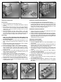
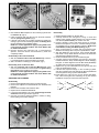
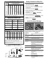
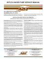
60FR PLUNGER PUMP SERVICE MANUAL
®
SPLIT MANIFOLD PLUNGER PUMP
60 FRAME [6760, 6761, 6767]
CAUTION: CAT PUMPS are positive displacement pumps. Therefore, a
properly designed pressure RELIEF OR SAFETY VALVE MUST BE
INSTALLED in the discharge piping. Failure to install such a relief mech-
anism could result in personal injury or damage to the pump or system.
CAT PUMPS does not assume any liability or responsibility for the
operation of a customer’s high pressure system.
INSTALLATION AND START-UP INFORMATION
Optimum performance of the pump is dependent upon the entire fluid system and will be obtained only
with the proper selection, installation of plumbing and operation of the pump and accessories.
SPECIFICATIONS: Maximum specifications refer to individual attributes. It is
not implied that all maximums can be performed simultaneously. If more
than one maximum is considered, check with your CAT PUMPS supplier to
confirm the proper performance and pump selection.
LUBRICATION: Fill crankcase with special CAT PUMP Oil per pump
specifications. [60FR-10 Qts.] DO NOT RUN PUMP WITHOUT OIL
IN CRANKCASE. Change initial fill after 50 hours running period. Thereafter,
change oil every 3 months or 500 hour intervals. OILER ADJUSTMENT
is vertical to start feed, horizontal to stop feed, dial to adjust flow rate.
Additional lubrication may be required with increased hours of operation
and temperature.
PUMP ROTATION: Pump was designed for forward rotation to allow optimum lubrication of the crosshead area. Reverse rotation is acceptable if the
crankcase oil level is increased slightly above center dot to assure adequate
lubrication.
PULLEY SELECTION: Select size of motor pulley required to deliver the
desired volume from Horsepower Requirement and Pulley Selection Chart.
MOTOR SELECTION: The motor or engine driving the pump must be of
adequate horsepower to maintain full RPM when the pump is under load.
Select the electric motor from the Horsepower Requirement Chart
according to required pump discharge volume, maximum pressure at the
pump and drive losses of approximately 3-5%. Consult the manufacturer of
gas or diesel engine for selection of the proper engine size.
Mount the pump on a rigid, horizontal surface in a manner to permit drainage
of crankcase oil. An uneven mounting surface will cause extensive damage to
the pump base. To minimize piping stress, use appropriate flexible hose to
inlet and discharge ports. Use the correct belt; make sure pulleys are
aligned. Excessive belt tension may be harmful to the bearings. Hand rotate
pump before starting to be certain shaft and bearings are free moving.
LOCATION: If the pump is used in extremely dirty or humid conditions, it is
recommended pump be enclosed. Do not store or operate in excessively high
temperature areas or without proper ventilation.
INLET CONDITIONS: Refer to complete Inlet Condition Check-List in this
manual before starting system. DO NOT STARVE THE PUMP OR RUN DRY.
C.A.T.: Installation of a C.A.T. (Captive Acceleration Tube) is recommended in
applications with stressful inlet conditions such as high temperatures, booster
pump feed, long inlet lines or quick closing valves.
DISCHARGE PLUMBING: OPEN ALL VALVES BEFORE STARTING
SYSTEM to avoid deadhead overpressure condition and severe damage to
the pump or system.
Install a Pulsation Dampening device mounted directly to the discharge line.
Be certain the pulsation dampener (Prrrrr-o-lator) is properly precharged for
the system pressure (see individual Prrrrr-o-lator data sheet).
A reliable Pressure Gauge should be installed near the discharge outlet of
the high pressure manifold. This is extremely important for adjusting pressure
and also for proper sizing of the nozzle or regulating devices. The pump is
rated for a maximum pressure; this is the pressure which would be read at
the discharge manifold of the pump, NOT AT THE GUN OR NOZZLE.
A Pressure Regulator or Unloader Valve must be installed to prevent
over pressurizing the pump in the event the discharge or downstream
plumbing becomes plugged or is turned off. Severe damage to the pump will
result if this condition occurs without a relief valve in the line. CAUTION:
Failure to install such a safety valve will void the warranty on the pump.
Discharge regulating devices should be at minimum pressure setting at
start-up. On systems over 2000 PSI SECONDARY PROTECTION is
recommended by installing a pop-off valve, safety valve or rupture disc.
START SYSTEM WITH ALL VALVES OPEN OR IN THE LOW PRESSURE
SETTING.
Use PTFE liquid (sparingly) or tape to connect accessories or plumbing.
Exercise caution not to wrap tape beyond the last thread to avoid tape from
becoming lodged in the pump or accessories. This condition will cause a
malfunction of the pump or system.
NOZZLES: A worn nozzle will result in loss of pressure. Do not adjust
pressure regulating device to compensate. Replace nozzle and reset
regulating device to system pressure.
PUMPED FLUIDS: Some fluids may require a flush between operations or
before storing. For pumping fluids other than water, contact your CAT
PUMPS supplier.
STORING: For extended storing or between use in cold climates, drain all
pumped fluids from pump and flush with antifreeze solution to
prevent freezing and damage to the pump. DO NOT RUN PUMP WITH
FROZEN FLUID.
Products described hereon are covered by one or more of the following U.S. patents 3558244, 3652188, 3809508, 3920356, 3930756 and 5035580
CAT PUMPS (U.K.) LTD.
World Headquarters
CAT PUMPS
1681 - 94th Lane N.E. Minneapolis, MN 55449 - 4324
Phone (612) 780-5440 — FAX (612) 780-2958
e-mail: [email protected]
www.catpumps.com
International Inquiries
FAX (612) 785-4443
e-mail: [email protected]
1 Fleet Business Park, Sandy Lane, Church Crookham, Fleet
Hampshire GU13 OBF, England
Phone Fleet 44 1252-622031 — Fax 44 1252-626655
N.V. CAT PUMPS INTERNATIONAL S. A.
®
The Pump with “Nine Lives”
Heiveldekens 6A, 2550 Kontich, Belgium
Phone 32- 3- 450.71.50 — Fax 32-3- 450.71.51
e-mail: [email protected]
CAT PUMPS DEUTSCHLAND GmbH
Buchwiese 2, D-65510 Idstein, Germany
Phone 49 6126-93030 — Fax 49 6126-930333
e-mail: [email protected]
Fig. A
Fig. B
Fig. C
SERVICING THE VALVES
REMOVING THE DISCHARGE MANIFOLD
Disassembly
1. Remove eight (8) M16 Hex Socket Head Bolts. (Fig. C)
2. To assure alignment use two M16 Studs (PN 88902) as
guides while removing manifold. Tap the back side of the
Discharge Manifold with a soft mallet and gradually work head
from pump. Properly support Discharge Manifold to avoid
damage to the Ceramic Plungers. (Fig. D)
1. Remove six (6) M70 Hex Valve Plugs. (Fig. A)
2. Under the Valve Plug is a Coil Spring and Washer. Remove
by hand.
3. Then thread an M12 bolt into the top of the Spring Retainer
and pull out the valve assembly (including Retainer, Spring,
Valve Seat, O-Ring and Back-up-Ring) from the valve
chamber. (Fig. B)
4. The valve assembly should remain together. If the valve
assembly separates, the parts can easily be removed without
any tools except for the Seat. Use a reverse pliers or slip the
head of a bolt under the edge of the Valve Seat to remove.
Reassembly
1.
2.
3.
4.
5.
6.
7.
8.
NOTE: For certain applications apply liquid gasket to the
o-ring crevices and seal surfaces. See Tech Bulletin 053
for model identification.
Examine the O-Rings on the Valve Seat and replace if cut or
worn. Lubricate the O-Rings before installing on the Valve
Seat.
Examine the surface of the Valve and Valve Seat for pitting,
grooves or wear and replace if necessary.
Examine the Spring for fatigue, scale or breaks and replace.
The Valve Assembly comes as one piece in the service kit.
Using individual parts, assemble Valve Retainer, Spring,
Valve and Seat (with O-Ring and Back-up-Ring) and snap
together securely.
Lubricate the O.D. of the Valve Assembly and the I.D. of the
valve chamber and press Valve Assembly squarely into
chamber until completely seated.
Replace Washer over top of Retainer, then Coil Spring.
Examine the O-Ring on the Valve Plug and replace if cut or
worn. Lubricate new O-Ring before installing on Valve Plug.
Exercise caution not to cut o-ring on threads of Valve Plug.
Lubricate O.D. of Valve Plug O-Ring and thread into Valve
Chamber. Exercise caution to avoid extruding O-Ring. Torque
to specifications in chart.
Fig. D
Fig. E
REMOVING THE INLET MANIFOLD
1. Remove the center four (4) M16 Hex Head Bolts and the two
(2) M16 Hex Nuts from the Studs.
2. Rotate Crankshaft to separate Inlet Manifold from the Crankcase.
3. Tap the rear of the Inlet Manifold with a soft mallet and gradually work from pump. NOTE: Exercise caution and keep Manifold
aligned with Plungers to avoid damage to the Plungers as the
Inlet Manifold is removed. (Fig. E)
SERVICING THE PACKINGS
Disassembly of the V-Packing
1. Place the crankcase side of the Inlet Manifold down on the
work surface.
2. Remove each V-Packing Cylinder by inserting screwdrivers in
opposite sides of the center machined groove and pry away
from Inlet Manifold. Then work out by hand. (Fig. F)
3. Next remove Spacer with Coil Springs by hand. Examine the
Coil Springs for fatigue or broken springs and replace as
needed.
4. Then with reverse pliers remove the Male Adapter,
V-Packings and Female Adapter.
5. Remove the Inlet Manifold Spacer from the three bottom ports
and examine O-Rings for cuts or wear. Replace as necessary.
Reassembly of the V-Packing
1. Insert the Female Adapter into the V-Packing Cylinder with
the “V” groove up. (Fig. H)
2. Next assemble both V-Packings, lubricate the outer surface
and insert into the V-Packing Cylinder with the “V” groove
up. (Fig.H)
Fig. F
Fig. G
Fig. H
3. Next install the Male Adapter into the V-Packing Cylinder with
the notches up. (Fig H)
4. Insert the Spacer with Coil Springs into the Seal Chamber
with the springs facing down. (Fig I)
5. Lubricate outer surface of V-Packing Cylinder and install new
O-Ring in groove. Press V-Packing Cylinder with O-Ring down
into seal chamber until completely seated.
NOTE: For certain applications apply liquid gasket to the
o-ring crevices and seal surfaces. See Tech Bulletin 053
for model identification.
6. Replace O-Rings and lubricate O.D. of Inlet Manifold
Spacers. Press into bottom seal chambers by hand until
completely seated.
Disassembly of the Lo-Pressure Seal
1. With the crankcase side of the Inlet Manifold up, examine
Lo-Pressure Seals for wear and replace as needed.
2. With a screwdriver carefully pry out old seals. (Fig J)
Reassembly of the Lo-Pressure Seal
1. With the crankcase side of the Inlet Manifold up, install
new Lo-Pressure Seals into seal chambers with garter spring
facing down. Press squarely into position.
NOTE: For certain applications apply liquid gasket to the
o-ring crevices and seal surfaces. See Tech Bulletin 053
for model identification.
SERVICING THE PLUNGERS
Fig. I
Reassembly
1. Replace Keyhole Washer on Plunger Rod.
2. Carefully examine each Plunger for scoring or cracks and
replace if worn. NOTE: Ceramic Plunger can only be installed
one direction (front to back). Do not force onto rod.
3. Examine Gasket, O-Ring and Back-up-Ring on Plunger
Retainer and replace if cut or worn. Lubricate O-Ring for ease
of installation and to avoid damaging O-Rings. NOTE: First
install Gasket, O-Ring then Back-up-Ring. (Fig K)
4. Apply a small amount of Loctite 242 and thread Plunger
Retainer onto Plunger Rod. Torque to specifications in chart.
5. Slip Seal Retainers over Plungers. Insert smaller diameter
first. NOTE: Line up Wicks with the oil holes in the Crankcase
and tabs down towards the Oil Pan.
6. Rotate Crankshaft and line up two outside Plungers.
7. Carefully replace Inlet Manifold onto Plungers and press
towards Crankcase. Keep manifold aligned to avoid damaging
Plungers. To assure alignment use two M16 studs (PN 88902)
as guides and remove when manifolds are in place.
8. Replace four (4) Hex Head Bolts and two (2) Hex Nuts and
torque to specifications in chart.
9. Lubricate the exposed O-Rings on the V-Packing Cylinder
and valve chamber walls and carefully slip Discharge Manifold
over Plungers and snug up to the Inlet Manifold.
10. Hand tighten the outer top two (2) Hex Socket Head Bolts
first. Then hand tighten the remaining six (6) Hex Socket
Head Bolts. Torque per chart and in this sequence.
Disassembly
5
1
3
7
1. Remove the Seal Retainers from the Ceramic Plungers.
2. Remove the Adapter Front Seal Retainer from the Rear Seal
Retainer.
3. Remove the used Wick and install new wick.
4. Replace Front and Rear Seal Retainer.
5. Loosen Plunger Retainer 4 to 5 turns. Push Plunger towards
Crankcase until Plunger Retainer pops out.
6. Unscrew and remove Plunger Retainer, Gasket, O-Ring,
Back-up-Ring and Ceramic Plunger.
0
0
0
0
0
0
0
0
8
4
2
6
Fig. J
Fig. K
SERVICING THE CRANKCASE SECTION
INLET CONDITION CHECK-LIST
1. While Manifolds, Plungers and Seal Retainers are removed,
examine Crankcase Seals for wear.
2. Check oil level and for evidence of water in oil.
3. Rotate Crankshaft by hand to feel for smooth bearing
movement.
4. Examine Crankshaft Oil Seal externally for drying, cracking
or leaking.
5. Consult factory or your local distributor if Crankcase
service is required.
See Section V of the Plunger Pump Service Video for
additional information.
PREVENTATIVE MAINTENANCE CHECK-LIST
Check
Daily
Clean Filters
Weekly 50 hrs. 500 hrs.*
1500 hrs.**
x
Oil Level/Quality
x
Oil Leaks
x
Water Leaks
x
Belts, Pulley
x
Plumbing
x
Initial Oil Change
x
Seal Change
x
Valve Change
x
Accessories
x
*If other than CAT PUMPS special multi-viscosity ISO68 oil is used, change
cycle should be every 300 hours.
**Each system’s maintenance cycle will be exclusive. If system performance
decreases, check immediately. If no wear at 1500 hours, check again at 2000
hours and each 500 hours until wear is observed.
**Remember to service the regulator/unloader at each seal servicing and check
all system accessories and connections before resuming operation.
TORQUE CHART
Pump Item
Pump Model
Thread
Tool Size
[Part No.]
Torque
in. lbs. ft. lbs. Nm
Plunger Retainer
M14
M30 Hex
520
43.4
59
Inlet Manifold Bolts
M16
M14 Hex
[25053]
565
47.0
64
Discharge Manifold Bolts
M16
M14 Allen
[33049]
565
47.0
64
Valve Plugs
M70
M41 Hex
1390
115.7 157
Crankcase Cover/
Bearing Cover Screws
M10
M17 Hex
[25083]
220
18.1
25
Connecting Rod Screws
M10
M17 Hex
[25083]
395
32.5
45
Bubble Oil Gauge
M28
Oil Gauge Tool
[44050]
45
3.6
5
TECHNICAL BULLETIN REFERENCE CHART
No.
Subject
Models
003
3FR - 68FR Accessory Drive Packages
3FR - 68FR Plunger Models
024
Lubrication of Lo-Pressure Seals
All Models
036
Cylinder and Plunger Reference Chart
All Models
043
Plunger Pump LPS and HPS Servicing
All Plunger Models
052
Plunger Rod and Stud Change - CR Pumps
3FR, 5FR, 15FR, 35FR, 60FR
053
Liquid Gasket
5FR, 7FR, 15FR, 35FR, 60FR
074
Piston and Plunger Pump Torque Chart
All Models
077
Oil Drain Kit
All Models
Inadequate inlet conditions can cause serious malfunctions in the best designed pump. Surprisingly, the simplest of things can cause the most severe
problems or go unnoticed to the unfamiliar or untrained eye. REVIEW THIS
CHECK-LIST BEFORE OPERATION OF ANY SYSTEM. Remember, no
two systems are alike, so there can be no ONE best way to set up a system.
All factors must be carefully considered.
INLET SUPPLY should be adequate to accommodate the maximum flow
being delivered by the pump.
❏ Open inlet shut-off valve and turn on water supply to avoid starving the
pump. DO NOT RUN PUMP DRY.
❏ Avoid closed loop systems especially with high temperature, ultra-high
pressure or large volumes. Conditions vary with regulating/unloader valve.
❏ Low vapor pressure fluids, such as solvents, require a booster pump and
C. A.T. (Captive Acceleration Tube) to maintain adequate inlet supply.
❏ Higher viscosity fluids require a positive head and a C. A.T. (Captive
Acceleration Tube) to assure adequate inlet supply.
❏ Higher temperature fluids tend to vaporize and require positive heads and
C. A.T. (Captive Acceleration Tube) to assure adequate inlet supply.
❏ When using an inlet supply reservoir, size it to provide adequate fluid to
accommodate the maximum output of the pump, generally a minimum of
6 to 10 times the GPM (however, a combination of system factors can
change this requirement); provide adequate baffling in the tank to eliminate
air bubbles and turbulence; install diffusers on all return lines to the tank.
INLET LINE SIZE should be adequate to avoid starving the pump.
❏ Line size must be a minimum of one size larger than the pump inlet fitting.
Avoid thick walled fittings, tees, 90 degree elbows or valves in the inlet line
of the pump to reduce the risk of flow restriction and cavitation.
❏ The line MUST be a FLEXIBLE hose, NOT a rigid pipe, and reinforced on
SUCTION systems to avoid collapsing.
❏ The simpler the inlet plumbing the less the potential for problems. Keep
the length to a minimum, the number of elbows and joints to a minimum
(ideally no elbows) and the inlet accessories to a minimum.
❏ Use pipe sealant to assure airtight, positive sealing pipe joints.
x
Oil Change
Review Before Start-Up
INLET PRESSURE should fall within the specifications of the pump.
❏ Acceleration loss of fluids may be increased by high RPM, high
temperatures, low vapor pressures or high viscosity and may require
pressurized inlet and C. A.T. (Captive Acceleration Tube) to maintain
adequate inlet supply.
❏ Optimum pump performance is obtained with +20 PSI (1.4 BAR) inlet
pressure and a C. A.T. for certain applications. With adequate inlet
plumbing, most pumps will perform with flooded suction. Maximum inlet
pressure is flooded to 50 PSI (3.5 BAR).
❏ After prolonged storage, pump should be purged of air to facilitate priming.
Disconnect any discharge port and allow fluid to pass through pump.
INLET ACCESSORIES are designed to protect against overpressurization,
control inlet flow, contamination or temperature and provide ease of servicing.
❏ A shut-off valve is recommended to facilitate maintenance.
❏ Installation of a C.A.T. (Captive Acceleration Tube) is essential in applications
with stressful conditions such as high temperatures, booster pump feed or
long inlet lines. Do not use C.A.T. with negative inlet pressure.
❏ A stand pipe can be used in some applications to help maintain a positive
head in the inlet line.
❏ Inspect and clean inlet filters on a regular schedule.
❏ A pressure gauge is recommended to monitor the inlet pressure and
should be mounted AS CLOSE TO THE PUMP INLET as possible. Short
term, intermittent cavitation will not register on a standard gauge.
❏ All accessories should be sized to avoid restricting the inlet flow.
❏ All accessories should be compatible with the solution being pumped to
prevent premature failure or malfunction.
BY-PASS TO INLET Care should be exercised when deciding the method of
by-pass from control valves.
❏ It is recommended the by-pass be directed to a baffled reservoir tank, with
at least one baffle between the by-pass line and the inlet line to the pump.
❏ Although not recommended, by-pass fluid may be returned to the inlet line
of the pump if the system is properly designed to protect your pump. When
using this method a PRESSURE REDUCING VALVE should be installed on
the inlet line (BETWEEN THE BY-PASS CONNECTION AND THE INLET
TO THE PUMP) to avoid excessive pressure to the inlet of the pump when a
flow sensitive regulating device is used. It is also recommended that a
THERMO VALVE be used in the by-pass line to monitor the temperature
build-up in the by-pass loop to avoid premature seal failure.
❏ A low-pressure, flexible cloth braid (not metal braid) hose should be used
from the by-pass connection to the inlet of the pump.
❏ Caution should be exercised not to undersize the by-pass hose diameter
and length. Refer to Technical Bulletin 64 for additional information on the
size and length of the by-pass line.
❏ Check the pressure in the by-pass line to avoid overpressurizing the inlet.
❏ The by-pass line should be connected to the pump inlet line at a gentle angle
of 45° or less and no closer than 10 times the pump inlet port diameter
e.g. 1-1/2" port size = 15" distance from pump inlet port.
Handy Formulas to Help You
HOSE FRICTION LOSS
PRESSURE DROP IN PSI PER 100 FT OF HOSE
WITH TYPICAL WATER FLOW RATES
Hose Inside Diameters, Inches
Water*
Flow
Gal/Min
1/4
5/16
3/8
1/2
5/8
3/4
1"
0.5
16
5
2
1
54
20
7
2
2
180
60
25
6
2
3
380
120
50
13
4
2
4
220
90
24
7
3
5
320
130
34
10
4
6
220
52
16
7
1
8
300
80
25
10
2
10
450
120
38
14
3
15
900
250
80
30
7
20
1600
400
121
50
12
25
650
200
76
19
30
250
96
24
40
410
162
42
50
600
235
62
60
370
93
*At a fixed flow rate with a given size hose, the pressure drop across a given hose length
will be directly proportional. A 50 ft. hose will exhibit one-half the pressure drop of a 100
ft. hose. Above values shown are valid at all pressure levels.
WATER LINE PRESSURE LOSS
Steel Pipe—Nominal Dia.
Brass Pipe—Nominal Dia.
1/4 3/8 1/2 3/4 1 11/4 11/2
Copper Tubing O.D. Type L
1/4 3/8 1/2 5/8 3/4 7/8
8.5 1.9
6.0 1.6
120 13 2.9 1.0
30 7.0 2.1
20 5.6 1.8
400 45 10 3.4 1.3
60 14 4.5 1.1
40 11 3.6
94 20 6.7 2.6
1/4 3/8 1/2 3/4
1
2
3
5
8
10
15
25
40
1 1 /4 1 /2
1
1
150 36 12 2.8
100 28 9.0 2.2
230 50 17 6.1 3.0
330 86 28 6.7 1.9
220 62 21 5.2 1.6
500 120 40 15 6.5
520 130 43 10 3.0
320 90 30 7.8 2.4
180 56 22 10
270 90 21 6.2 1.6
190 62 16 5.0 1.5
120 44 20
670 240 56 16 4.2 2.0
470 150 40 12 3.8 1.7
330 110 50
66 17 8.0
39 11 5.0
550 200 88
37
17
23
11
52
29
40
19
210 107
48
61
28
60
80
100
RESISTANCE OF VALVES AND FITTINGS
Nominal
Pipe
Inside
Size
Diameter
Inches
Inches
Equivalent Length of Standard Pipe in Feet
Gate
Valve
Globe
Valve
Angle
Valve
45˚
Elbow
90˚
Elbow
180˚
Close
Ret
Tee
Thru
Run
Tee
Thru
Branch
1/2
3/4
1
11/4
11/2
0.622
0.824
1.049
1.380
1.610
0.41
0.54
0.69
0.90
1.05
18.5
24.5
31.2
41.0
48.0
9.3
12.3
15.6
20.5
24.0
0.78
1.03
1.31
1.73
2.15
1.67
2.21
2.81
3.70
4.31
3.71
4.90
6.25
8.22
9.59
0.93
1.23
1.56
2.06
2.40
3.33
4.41
5.62
7.40
8.63
2
2.067
2.469
3.068
4.026
1.35
1.62
2.01
2.64
61.5
73.5
91.5
120.0
30.8
36.8
45.8
60.0
2.59
3.09
3.84
5.03
5.55
6.61
8.23
10.80
12.30
14.70
18.20
23.90
3.08
3.68
4.57
6.00
11.60
13.20
16.40
21.60
2 1/2
3
4
Q. I have to run my pump at a certain RPM. How do I figure
the GPM I’ll get?
Rated GPM
A. Desired GPM = Desired RPM x
Rated RPM
Q. Is there a simple way to find the approximate horsepower
I’ll need to run the pump?
A. Electric Brake
GPM x PSI
=
Horsepower Required
1460
Arriving at a total line pressure loss, consideration should then be given to
pressure loss created by values, fittings and elevation of lines.
If a sufficient number of values and fittings are incorporated in the system to
materially affect the total line loss, add to the total line length, the equivalent
length of line of each valve or fitting.
Supply Line
Bypass Line
(from regulator or unloader)
→
One or several of the conditions shown in the chart below may
contribute to cavitation in a system resulting in premature wear,
system downtime and unnecessary operating costs.
CONDITION
Inadequate inlet
line size
Water hammering
fluid acceleration/
deacceleration
Rigid Inlet Plumbing
Excessive Elbows in
Inlet Plumbing
Excessive Fluid
Temperature
Air Leaks in Plumbing
Agitation in Supply
Tank
D
High Viscosity Fluids
→
→
→
→
→
MIN. 4"
→
1.5 x D (Min.)
Flexible Hose
to Pump
→
→
FILTER
MIN. 4"
Minimum
Fluid
Level
Bypass Line
(from regulator or
unloader)
Clogged Filters
Minimum Two Baffles
Sealed at Bottom
)
Avoid Cavitation Damage
(Dia of pipe)
T
X
Level Sensing
Device
(Consult
Engine Mfr.)
Q. How do I calculate the torque for my hydraulic drive
system?
GPM x PSI
A. Torque (ft. lbs.) = 3.6
RPM
TYPICAL RESERVOIR TANK
RECOMMENDED 6 TO 10 TIMES SYSTEM CAPACITY
(Standard 85%
Mech. Efficiency)
Q. What size motor pulley should I use?
Pump RPM
A. Pump Pulley (Outer Diameter) x
Motor/Engine RPM
(
PRESSURE DROP IN PSI PER 100 FEET
Water
GPM
Q. How can I find the RPM needed to get specific GPM
(Gallons Per Minute) I want?
Rated RPM
A. Desired RPM = Desired GPM x
Rated GPM
SOLUTION
Increase line size to the inlet port or one size
larger
● Install C.A.T. Tube
● Move pump closer to fluid supply
●
Use flexible wire reinforced hose to absorb
pulsation and pressure spikes
● Keep elbows to a minimum and less than 90°
●
Use Thermo Valve in bypass line
Do not exceed pump temperature specifications
● Substitute closed loop with baffled holding tank
● Adequately size tank for frequent or high
volume bypass
● Pressure feed high temperature fluids
● Properly ventilate cabinets and rooms
● Check all connections
● Use Teflon tape
● Size tank according to pump output —
Minimum 6-10 times system GPM
● Baffle tank to purge air from fluid and
separate inlet from discharge
● Verify viscosity against pump specifications
before operation
● Elevate fluid temperature enough to reduce
viscosity
● Lower RPM of pump
● Pressure feed pump
● Increase inlet line size
● Perform regular maintenance or use clean
filters to monitor build up
● Use adequate mesh size for fluid and pump
specifications
●
●
DIAGNOSIS AND MAINTENANCE
•
•
•
•
Worn nozzle
Belt slippage
Air leak in inlet plumbing
Pressure gauge inoperative or not
registering accurately
• Relief valve stuck, partially plugged or improperly
adjusted
• Worn seat or valves
• Inlet suction strainer clogged or improperly sized
• Worn V-Packing. Abrasives in pumped fluid, severe
cavitation; inadequate water supply, stressful inlet
conditions
• Fouled or dirty inlet or discharge valves
• Worn inlet or discharge valves
• Leaky discharge hose
• Pulsation, pump runs
extremely rough,
pressure low
• Faulty Pulsation Dampener
• Restricted inlet or air entering inlet plumbing
• Stuck inlet or discharge valve
SOLUTION
•
•
•
•
Replace nozzle of proper size.
Tighten or replace; use correct belt.
Use PTFE liquid or tape.
Check pressure with new gauge and replace as needed.
• Clean and reset relief valve to system pressure and
correct by-pass. Check supply tank for contamination.
• Clean or replace with valve kit.
• Use adequate size for inlet pump connection and fluid
being pumped. Clean frequently.
• Replace Packing, install and maintain proper filter, check
line size and flow available to pump. Install a C.A.T.
• Clean inlet and discharge valve assemblies.
• Replace with valve kit.
• Replace hose. Check connections.
• Check precharge (should be 30-50%) of system pressure
or replace as needed.
• Check filters and clean as needed. Check fittings and
use PTFE liquid or tape for airtight connection.
• Clean or replace valve. Check supply tank for
contamination.
• Water leakage from
under the manifold
*Slight leakage
• Worn V-Packings and Lo- Pressure Seals
• Replace with seal kit, check inlet pressure and
system temperature, use inlet pressure regulator
in inlet line.
• Oil leak between
crankcase and pumping
section
• Worn crankcase oil seals
• Replace crankcase oil seals, and change crankcase oil.
• Oil leaking in the area
of crankshaft
• Worn crankshaft oil seal
• Bad bearing
• Cut or worn o-ring on bearing case
• Replace damaged oil seals.
• Replace bearing.
• Replace o-ring on bearing case.
• Excessive play in the end
of the crankshaft
• Worn bearing
• Replace bearing, and check for proper belt tension.
• Water in crankcase
• Humid air condensing into water inside
of the crankcase
• Change oil every 3 months or 500 hour intervals using
special CAT PUMP Premium Grade Oil, PN 6100 (Case)
6107 (Bottle) (other approved oil every month or 200
hours.)
• Replace seals. Follow proper installation procedure.
Contact CAT PUMPS supplier for crankcase servicing.
• Worn or improperly installed crankcase oil seals
• Oil leaking at the rear
portion of the crankcase
• Damaged or improperly installed oil gauge,
crankcase cover or drain plug O-ring
• Replace oil gauge, crankcase cover or drain plug
O-ring. Thread in oil gauge and drain plug hand tight to
avoid extruding o-ring.
• Loud knocking noise
in pump
• Pulley loose on crankshaft
• Worn bearing, connecting rod or crankshaft
• Stressful inlet conditions
• Check key and tighten set screw.
• Consult Cat Pumps supplier for crankcase servicing.
• Install C.A.T. (Captive Acceleration Tube).
• Frequent or premature
failure of the packing
•
•
•
•
•
•
•
•
•
•
•
•
• Strong surging at the
inlet and low pressure
• Foreign particles in the inlet or discharge valve
or worn inlet and/or discharge valves
Scored plungers
Over pressure to inlet manifold
Abrasive material in the fluid being pumped
Excessive temperature of pumped fluid
Running pump dry
Starving pump of adequate fluid
Replace plungers.
Reduce inlet pressure per instructions.
Install proper filtration on pump inlet plumbing.
Reduce fluid inlet temperature to specifications.
DO NOT RUN PUMP WITHOUT WATER.
Increase supply line to one size larger than inlet port size.
• Check for smooth surfaces on inlet and discharge
valve seats. Replace with kit if pitted or worn.
• Check supply tank for contamination. Install and
regularly clean filter. Do not pump abrasive fluids.
PN 30051
• Low Pressure
PROBABLE CAUSE
Rev. D 12/98
PROBLEM