1
ultimail
Service Manual
Chapter 1
Introduction
Chapter 2
Service Mode
Chapter 3
Mail handler
Chapter 4
Feed Unit
Videos
Video’s
1. Removing the Mail handler Housing
2. Separating the Upper and Lower Assemblies
3. Disassemble the Lower Assembly
4. Removing the Print Assembly
5. Removing the Sealing Station
6. Removing the Encoder Unit
7. Disassemble the Feed Unit
8. Disassemble the Upper Separation Unit
Main Index
ultimail mailingsystem – Service documentation
Chapter 1 General
FRANCOTYP-POSTALIA
ultimail
Service Manual
Andreas Nagel SMT Tel. 03303 / 525-711 Fax:-712 !!vertraulich!! Änderungsstand März 2003
USA ver.
1.00 translated By: Zac Moody, Doug Michaels, And Mr. Andreas Nagel April, 2003
Seite 1
ultimail mailingsystem – Service documentation
Chapter 1 General
Chapter 1
FRANCOTYP-POSTALIA
General
CONTENTS
1
A SHORT DESCRIPTION OF THE ULTIMAIL
1.1
1.2
2
Safety Tips
Safety Information
5
5
TECHNICAL DATA
6
2.1
3
4
Equipment
8
THE PRINCIPLE OF THE PRINTING METHOD
9
3.1
The birth of the Thermal InkJet (TIJ) Technology...
3.1.1
TIJPrinter Element:
3.1.2
Operation:
3.1.3
Bubble formation and droplet ejection
9
9
9
10
THE INK CARTRIDGE FOR THE ULTIMAIL
4.1
5
2
Hewlett-Packard (HP) Inkjet Product Evolution - TIJ 2.5
INK CARTIDGE SERVICE ON THE HP SERVICE STATION
10
10
11
Main Menu
1
A SHORT DESCRIPTION OF THE ULTIMAIL
Andreas Nagel SMT Tel. 03303 / 525-711 Fax:-712 !!vertraulich!! Änderungsstand März 2003
USA ver.
1.00 translated By: Zac Moody, Doug Michaels, And Mr. Andreas Nagel April, 2003
Seite 2
ultimail mailingsystem – Service documentation
Chapter 1 General
FRANCOTYP-POSTALIA
The ultiMAIL is a digital postage meter with horizontal letter transport and ink
jet technology (ink jet print with two ink cartridges arranged side by side).
Structure In its basic version, the metering system consists of the postage
meter, manual positioned and catch tray.
The postage meter is available as model
– UltiMAIL 60 with a processing speed up to 3,500 letters per
hour
– UltiMAIL 90 with a processing speed up to 5,500 letters per
hour
Menu-supported
User interface
The prompt facility in the lit display will you lead to the desired results in a fast
and safe way. You simply follow the instructions in the display, whether for
setting the meter imprint, modifying the system settings or service functions,
e.g. changing cartridges.
Help
No illegal entries are allowed by the ultiMAIL – you are informed by an
appropriate message. A help function offers additional advice and support.
Metering
On one glance, the home menu will show you the current settings for the
meter imprint. You simply position the letter – the ultiMAIL will size the letter,
meter it and place it in the catch tray ready for dispatch.
You can meter
– Mail pieces up to a thickness of ¼" (6.3 mm) of an ink absorbent material.
– Self-adhesive labels.
Logo imprint ultiMAIL prints a logo of your choice on every mail piece.
TELESET
Load postage using the TELESET procedure via the built-in modem – its fast,
comfortably and, if necessary, 24 hours a day.
Protection against
The MasterCard/User Card functionality protects the ultiMAIL against
unauthorized use and facilitates the assignment of individual access rights.
Additional functions
You will quickly appreciate the following functions:
– Account function. Recording and accounting of postage according to
accounts.
– 6 short codes for frequently used postage imprint settings.
– Stamp of receipt. Imprint ‘received on: …’ for stamping incoming mail.
– Printing of account data, postage register states, and system information.
– Warning in case of high postage and too low amount of postage available.
– Print offset for changing the postage imprint position on the envelope.
– Tele diagnostic. You can transfer important system data via the built-in
modem to the Francotyp-Postalia service.
Flexible and up to date
New logos, type of mail endorsements or rate changes of the United States
Postal Service – you can easily load the latest data in your ultiMAIL.
Options
The following components are available for functionality extension:
– Internal scale. When the equipment includes an internal scale, the ‘rate
calculation’ function is available. The ultiMAIL calculates the postage on the
basis of selected mailing data in a fast and reliable way. Postage and type of
mail endorsement are set automatically.
– Label dispenser to print self-adhesive labels for large/thick mail pieces.
– Sealer ultiMAIL 60. Automatic sealer for the ultiMAIL 60 to moisten and
seal letters. The letters are positioned manually.
– Feeder ultiMAIL 90. Automatic feeder with sealer for the
ultiMAIL 90. The letters are separated from the stack,
Andreas Nagel SMT Tel. 03303 / 525-711 Fax:-712 !!vertraulich!! Änderungsstand März 2003
USA ver.
1.00 translated By: Zac Moody, Doug Michaels, And Mr. Andreas Nagel April, 2003
Seite 3
ultimail mailingsystem – Service documentation
Chapter 1 General
FRANCOTYP-POSTALIA
Optionally moistened and sealed, and fed to the ultiMAIL 90
postage meter.
Andreas Nagel SMT Tel. 03303 / 525-711 Fax:-712 !!vertraulich!! Änderungsstand März 2003
USA ver.
1.00 translated By: Zac Moody, Doug Michaels, And Mr. Andreas Nagel April, 2003
Seite 4
ultimail mailingsystem – Service documentation
Chapter 1 General
1.1
FRANCOTYP-POSTALIA
Safety Tips
The ultiMAIL is a digital metering system with an inkjet printer for metering letter mail.
The ultiMAIL complies with the pertinent safety regulations for office information equipment.
Please observe the following tips for your own safety:
Qualified personnel authorized by Francotyp-Postalia only do • Installation and commissioning of the
metering system ultiMAIL.
• Only operate the ultiMAIL system on a grounded single-phase power socket.
• Use only the power and modem cables provided or approved by Francotyp-Postalia.
Make sure that cables are not damaged.
• Make sure the socket for connecting the ultiMAIL is close by and easily accessible at all times.
• Do not remove any part of the safety and protective equipment. Do not make them inoperative.
Do not remove any parts of the housing.
• Do not reach into the danger areas marked with a danger symbol.
• Keep long hair, fingers, loose clothing pieces, shawls and jewelery away from moving machine parts.
• Never cover the ventilation slots in the housing.
• Pull out the mains plug in the event of danger! Call the after-sales service.
• Make sure that no liquids or foreign objects penetrate the interior of the ultiMAIL. If this happens, pull
out the mains plug immediately. Have the ultiMAIL metering system checked by Francotyp-Postalia
service before starting it up again.
• Use the ‘Sealer ultiMAIL 60’ only with the ultiMAIL 60 postage meter. It is not possible to operate the
sealer without the ultiMAIL 60 postage meter.
• Use the ‘Feeder ultiMAIL 90’ only with the ultiMAIL 90 postage meter. It is not possible to operate the
feeder without the ultiMAIL 90 postage meter.
• Only use original ink cartridges from Francotyp-Postalia. Observe the information enclosed with
every cartridge.
• Only use the batteries provided by Francotyp-Postalia. Observe the instructions enclosed with the
battery for correct use and disposal.
• Only have maintenance and repair work done by qualified personnel authorized by FrancotypPostalia. Otherwise your warranty will be voided. You will be liable for any damages.
1.2 Safety Information
Andreas Nagel SMT Tel. 03303 / 525-711 Fax:-712 !!vertraulich!! Änderungsstand März 2003
USA ver.
1.00 translated By: Zac Moody, Doug Michaels, And Mr. Andreas Nagel April, 2003
Seite 5
ultimail mailingsystem – Service documentation
Chapter 1 General
FRANCOTYP-POSTALIA
General
Safety Tips:
CAUTION: Serious injury!
Before opening the machine make sure that the power cord has
been disconnected. The machine may continue to hold voltage,
even after the power has been disconnected. This may cause
serious injury or death, so please use caution when opening!
CAUTION: Neutral Fusing!
For continued protection against risk of fire and machine damage.
Replace fuses only with the same type and rating that has been UL
approved.
Attention!
The UltiMAIL utilizes a lithium battery to retain its own memory.
Only replace this battery with a FP UltiMAIL replacement lithium
battery. This lithium battery may not be recharged, or substituted.
CAUTION: Danger of explosion!
Explosion may result if the battery is incorrectly replaced. Only
Replace with the same or equivalent type of battery recommended
by the manufacturer. Dispose of used batteries according to the
manufacturers instructions.
2 TECHNICAL DATA
Andreas Nagel SMT Tel. 03303 / 525-711 Fax:-712 !!vertraulich!! Änderungsstand März 2003
USA ver.
1.00 translated By: Zac Moody, Doug Michaels, And Mr. Andreas Nagel April, 2003
Seite 6
ultimail mailingsystem – Service documentation
Chapter 1 General
FRANCOTYP-POSTALIA
Dimensions
(Length x Width x Height)
564 x 400 x 273 mm ultiMAIL 60/ultimail 90
With Feed tray and Catch tray
564 x 400 x 299 mm … and scale*
807 x 400 x 273 mm ultiMAIL 60
With Sealer and Catch tray
807 x 400 x 299 mm … and scale*
1028 x 400 x 273 mm ultiMAIL 90
With Automatic Feeder and Catch tray
1028 x 400 x 299 mm … and scale*
Weight
19.6lb (8.9 kg) Postage Machine ultiMAIL 60/ultimail 90
21.2lb (9.6 kg) With scale* and Tape Dispenser*
0.9lb (0.4 kg) Catch Tray
0.9lb (0.4 kg) Feed Tray
9.3lb (4.2 kg) Sealing Unit for ultiMAIL 60
21.7lb (9.7 kg) Automatic Feeding Unit ultiMAIL 90
Power connection
100-120V / 60 Hz
Power consumption
max. 70 W Postage Machine ultiMAIL 60
max. 70 W Postage Machine ultiMAIL 90
max. 50 W Automatic Feeder ultiMAIL 90
Battery
3.6 V / 2 Amps / 20 mA, part number (90.4701.8004.00)
Operating Temperature: -67 °F to 185°F
Speeds
3,500 Letters /hour ultiMAIL 60 = 60 Letters/min
5,500 Letters /hour ultiMAIL 90 = 90 Letters/min.
Display
LCD, illuminated, 320 x 240 Pixel
Print System
Ink Jet Technology (with 2 cartridges)
Print Range max. 155 x 24 mm
Print Range 300 dpi x 300 dpi (With Red ink cartridge)
Print Cartridge usage:
10 letters/day the Ink Cartridges will yield approx. 10,000 imprints
300 letters/day the Ink Cartridges will yield approx. 20,000 imprints
Note: Approximate values are based on letters processed
in one continuous run.
Noise Levels
< 65 dB(A) Postage Machine ultiMAIL 90 with Automatic Feeder*
62 dB (A) Postage Machine ultiMAIL 60 with Sealer*
60 dB (A) Postage Machine (Stand alone)
Andreas Nagel SMT Tel. 03303 / 525-711 Fax:-712 !!vertraulich!! Änderungsstand März 2003
USA ver.
1.00 translated By: Zac Moody, Doug Michaels, And Mr. Andreas Nagel April, 2003
Seite 7
ultimail mailingsystem – Service documentation
Chapter 1 General
FRANCOTYP-POSTALIA
2.1 Equipment
Standard
–
–
–
–
–
–
–
–
–
–
–
–
–
Feed tray
Letter catch (adjustable, to max.6X9)
Postage download via integrated modem (TDC)
System clock with back-up battery
Chip Card Reader
2 MasterCard’s
Standard USPS Endorsements
10 accounts (ultiMAIL 60) / 50 accounts (ultiMAIL 90)
6 Memory Functions
6 short memory settings
Low postage warning
High postage value warning
9-pin serial interface/connection for external devices
–
Integrated scale maximum weight: 11lbs (5 kg)
Smallest display value: 0.1oz.
Weighing accuracy: from 0 to 4.9lb
from 5 to 11lb
Label dispenser
Sealer ultiMAIL 60 (for postage machine ultiMAIL 60 only)
Feeder ultiMAIL 90 (automatic feeder with sealer for postage machine
ultiMAIL 90 only. Loading capacity of #10 envelopes is 100 letters but
not to exceed 50mm max. Loading capacity of postcards is 50 but not to
exceed 40mm max. )
User Cards
Upgradeable to 50 cost account (only for ultiMAIL 90)
Options
–
–
–
–
–
Andreas Nagel SMT Tel. 03303 / 525-711 Fax:-712 !!vertraulich!! Änderungsstand März 2003
USA ver.
1.00 translated By: Zac Moody, Doug Michaels, And Mr. Andreas Nagel April, 2003
Seite 8
ultimail mailingsystem – Service documentation
Chapter 1 General
3
FRANCOTYP-POSTALIA
THE PRINCIPLE OF THE PRINTING METHOD
3.1 The birth of the Thermal InkJet (TIJ) Technology...
•
In 1979 John Vaught, a researcher at the HP laboratories in Palo Alto, was
Brewing coffee when his coffee machine gave him an idea for using heat to
pump droplets of ink. The result was an ink jet printer unit that he called the side
shooter.“
3.1.1
TIJPrinter Element:
Orifice plate
Orifice
Heater
Photoimageable polymer
Refill channel
Silicon substrate
3.1.2
Operation:
Core
1 to 5 µs.
10 µs
200 µs
Ink resupply
Heating element
Produces ink
bubbles
Meniscus
Contracts and
Draws in new ink
Andreas Nagel SMT Tel. 03303 / 525-711 Fax:-712 !!vertraulich!! Änderungsstand März 2003
USA ver.
1.00 translated By: Zac Moody, Doug Michaels, And Mr. Andreas Nagel April, 2003
Seite 9
ultimail mailingsystem – Service documentation
Chapter 1 General
3.1.3
Bubble formation and droplet ejection
1. At rest
4. Meniscus contracts
4
FRANCOTYP-POSTALIA
2. Bubble formation,
droplet ejection
5. Secound bubble formation
3. Bubble collapses
6. Bubble collapses,
droplet end separates
(double pulse)
THE INK CARTRIDGE FOR THE ULTIMAIL
4.1 Hewlett-Packard (HP) Inkjet Product Evolution - TIJ 2.5
¾Introduced in April 1995 in the DeskJet-Series 850c
¾ TIJ 2.5 (Generation 2.5 Thermal Inkjet)
¾ 300 orifices, @ 12 kHz (DPS)
¾ 600 DPI Black, 4 - 8 PPM
¾ Colors: Black, Cyan, Yellow & Magenta, Red,
Postal Red (Fluorescent), and Blue
Andreas Nagel SMT Tel. 03303 / 525-711 Fax:-712 !!vertraulich!! Änderungsstand März 2003
USA ver.
1.00 translated By: Zac Moody, Doug Michaels, And Mr. Andreas Nagel April, 2003
Seite 10
ultimail mailingsystem – Service documentation
Chapter 1 General
5
FRANCOTYP-POSTALIA
INK CARTIDGE SERVICE ON THE HP
SERVICE STATION
Service Goal: To clean the ink cartridge and assure trouble free performance for the
duration of its service life.
Spitting
Capping
HP
Service Station
Functions
Wiping
Priming
-
Spitting
Simultaneous „ spitting of all orifices into an ink sump (docking station)
-
Capping
Seals all orifices to prevent them from drying up due to the evaporation of ink solvents.
-
Wiping
Wipes off any ink residues or dried ink from the area around the orifices.
-
Priming
A specific predetermined amount of ink is used to clean the orifices and eliminate any air bubbles
inside the print head.
Andreas Nagel SMT Tel. 03303 / 525-711 Fax:-712 !!vertraulich!! Änderungsstand März 2003
USA ver.
1.00 translated By: Zac Moody, Doug Michaels, And Mr. Andreas Nagel April, 2003
Seite 11
ultimail mailingsystem – Service documentation
Chapter 2 - Servicemode
Chapter 2
FRANCOTYP-POSTALIA
Service mode
CONTENTS
2
SERVICE MODE ULTIMAIL
2.1
Entering the Service Mode:
2.2
Service mode for Auto Feeder/ Sealer
2.3
The Service Menu Structure
2.3.1
Service Menu 1 / S1: Test Functions
2.3.2
Service menu 1 / S2: General Settings
2.3.3
Service menu 1 / S3: Print - Settings
2.3.4
Service menu 1: S4: Set Security Settings
2.3.5
Service menu 1: S5: Information Display / Print out
2.3.6
Service menu 1: S6: Set Periphery
2.3.7
Service menu 1: S7: Phone Numbers
2.3.8
Service menu 1: S8: More
2.3.9
Service menu 2: S1:Previous
2.3.10
Service menu 2: S2: PC Service Functions
2.3.11
Service menu 2: S3: Service Interval
2.3.12
Service menu 2: S4: Restart
2.3.13
Service menu 2: S5: Reload Software
2
2
2
3
4
8
10
12
14
17
17
18
18
19
20
20
21
Main Menu
J. Tolksdorf SMT Tel. 03303 / 525-714 Fax:-712 !!vertraulich!! chapter 2 Änderungsstand 03. April 2003
USA ver.
1.00 translated By: Zac Moody, Doug Michaels, And Mr. Andreas Nagel April, 2003
Page 1
ultimail mailingsystem – Service documentation
Chapter 2 - Servicemode
FRANCOTYP-POSTALIA
2 SERVICE MODE ULTIMAIL
2.1
1.
2.
3.
4.
5.
Entering the Service Mode:
Insert Your Dealer Card (With the chip face down!)
Press and hold down 1, 3, 8, while powering the machine on.
The machine will emit 1 short beep.
Then release the keys
The Machine enters the Service program and emits 4 double beeps.
There are two Service Menus. To toggle between the two service menus press the (more) key or
(previous) key.
Service Menu 1
S1: Test Function
S2: General Settings
S3: Print – Settings
S4: Security settings
S5: Show / Print Information
S6: Optional Enhancements
S7: Change phone numbers
S8: More
Service Menu 2
S1: Previous
S2: PC Service Functions
S3: Service interval
S4: Restart
S5: Reload Machine Software
S6:
S7:
S8:
For easy access the soft keys S1, S2, etc… are positioned around the display and are outlined in this
service section.
Note:
An authorized FP Technician can only access these functions with an authorized dealer
card. Only access those areas in the service mode, which are outline in this chapter.
Some of the functions may seriously effect the operation of the machine. Take caution
when performing service functions!
2.2 Service mode for Auto Feeder/ Sealer
The Service Menus for the Auto Feeder/Sealer will only become visible when connected to the
UltiMAIL System.
J. Tolksdorf SMT Tel. 03303 / 525-714 Fax:-712 !!vertraulich!! chapter 2 Änderungsstand 03. April 2003
USA ver.
1.00 translated By: Zac Moody, Doug Michaels, And Mr. Andreas Nagel April, 2003
Page 2
ultimail mailingsystem – Service documentation
Chapter 2 - Servicemode
2.3
FRANCOTYP-POSTALIA
The Service Menu Structure
Service
SERVICE-MODE 1
SHOW /PRINT
INFORMATION
S1
TESTFUNCTIONS
S2
GENERAL
SETTINGS
OPTIONAL
ENHANCEMENTS
S6
S3
PRINT
SETTINGS
CHANGE PHONE
NUMBERS
S7
SECURITY
MORE
SETTINGS
PLEASE SELECT A MAIN GROUP.
S4
1
S8
2
ABC
3
DEF
HOME
LABEL
GHI
5
JKL
6
MNO
BACK
SETUP
PQRS
8
TUV
9
WXYZ
4
7
>>
S5
0
INFO
Enter
TELESET
START
STOP
C/CE
+
Read
Register
Service
SERVICE-MODE 2
RELOAD
MACHINE SOFTWARE
<<
S1
PREVIOUS
S5
S2
PC-SERVICEFUNCTION
S6
S3
SERVICE
INTERVAL
S7
RESTART
S4
S8
PLEASE SELECT A MAIN GROUP.
1
4
7
2
ABC
3
DEF
GHI
5
JKL
6
MNO
PQRS
8
TUV
9
WXYZ
HOME
LABEL
BACK
SETUP
Enter
TELESET
START
STOP
INFO
0
+
C/CE
Read
Register
J. Tolksdorf SMT Tel. 03303 / 525-714 Fax:-712 !!vertraulich!! chapter 2 Änderungsstand 03. April 2003
USA ver.
1.00 translated By: Zac Moody, Doug Michaels, And Mr. Andreas Nagel April, 2003
Page 3
ultimail mailingsystem – Service documentation
Chapter 2 - Servicemode
2.3.1
FRANCOTYP-POSTALIA
Service Menu 1 / S1: Test Functions
Service
Tests Some functions of the machine
TEST FUNCTIONS
MODEM-TEST
DISPLAY TEST
S1
ENCODER-TEST
KEYBOARD TEST
S2
SERIAL INTERFACE
S4
Service
S6
CONTACT- TEST
MOTOR TEST
S3
S5
MORE
S7
>>
S8
Tests Some functions of the machine
TEST FUNCTIONS
<<
S1
S2
PREVIOUS
SENSOR-TEST
S5
S6
CALIBRATION
S3
S4
SENSOR LABEL DISP.
CALIBRATION
SENSOR PRINT START
S7
S8
J. Tolksdorf SMT Tel. 03303 / 525-714 Fax:-712 !!vertraulich!! chapter 2 Änderungsstand 03. April 2003
USA ver.
1.00 translated By: Zac Moody, Doug Michaels, And Mr. Andreas Nagel April, 2003
Page 4
ultimail mailingsystem – Service documentation
Chapter 2 - Servicemode
FRANCOTYP-POSTALIA
Test function S1: Display test
This will test the graphics and pixels of the display
Attention:
To exit from the display test press the BACK key.
Test function S2: Keyboard test
In the keyboard test, press each of the keys on the control panel. In the display the keys will become
darkened when pressed. If they do not become darkened, this could mean that the keyboard is
defective and needs to be replaced.
Attention:
To exit the keyboard test, wait 5 seconds and the test will automatically exit, as long as no keys
have been depressed.
Test function S3: Motor test
S1: Letter Transport
In this motor test the letter transport motor is turned on.
Attention:
To exit from the test press the BACK key.
S2: Print Cartridge motor
In this test the print heads are driven into the print position by pressing S2, if S2 is pressed again the
print heads will be driven into the sealing position.
S3: Label Dispenser motor
In the label motor test, place one label into the label feeder, by pressing S3 the label will be feed onto
the letter transport belt. The label can then be ejected with the letter transport key S1.
S4: Sealer motor
By pressing S4, this test turns on and off the introduction motor, which controls the feeding to the
sealer
S5: Feeder motor
By pressing S5, this test turns on and off the introduction motor, which also controls the separator
roller.
S6: Motor status report
This test will run through all of the tests listed above, and then display motor information.
Test Function S4: Serial Interface
S1
S2
S3
S4
UART1 Data send
OUT
RTS – CTS
OUT
DTR-DSR
OUT
Baud Rate
2400
UART1 Data send
OUT
RTS – CTS
OUT
DTR-DSR
OUT
S5
S6
S7
S8
Function of the serial interface 1 (and 2 if inserted) can be tested. In addition either a service plug or
PC connection with appropriate software is necessary. At the present time this function is not yet
available.
J. Tolksdorf SMT Tel. 03303 / 525-714 Fax:-712 !!vertraulich!! chapter 2 Änderungsstand 03. April 2003
USA ver.
1.00 translated By: Zac Moody, Doug Michaels, And Mr. Andreas Nagel April, 2003
Page 5
ultimail mailingsystem – Service documentation
Chapter 2 - Servicemode
FRANCOTYP-POSTALIA
The service plug can be manufactured however this option is currently not available:
Below is a wiring diagram for the 9-pin serial service plug.
The following pins must be bridged:
• Pin 2 und Pin3
• Pin 7 und Pin 8
• Pin 4 und Pin 6
With the S4 key the data transfer rate for all installed interfaces can be changed (at present SW ver.
2.00 does not have this function).
Test Function S5: Modem-Test
The internal connection between meter and modem is tested. Inquiries are sent in each case and wait
for the answer. Additionally the modem version is selected and indicated.
Test Function S6: Encoder-Test
The Encoder system is examined. The number of Encoder impulses is measured and any faulty
measurements are indicated in the display. A faulty measurement indicates the deviation between
what the expected measurement should be and the measured impulse number. If either occurs,
replacement or adjustment of the encoder may be needed.
Attention:
To exit from the test press the BACK key.
Test Function S7: Contact-Test
The following contacts are examined:
Test
Chip card
Con Prot Pen 0
Cartridge Pen 0
Con Prot Pen 1
Cartridge Pen 1
Attention:
Attention!
Connection between card readers and smart card tests
Connection to the "Consumer Protection" tests = chip at the print head 0
Connection to the print head tests 0
Tests connection to the "Consumer Protection" = chip at the print head 1
Tests connection to the print head 1
To exit from the test press the BACK key.
J. Tolksdorf SMT Tel. 03303 / 525-714 Fax:-712 !!vertraulich!! chapter 2 Änderungsstand 03. April 2003
USA ver.
1.00 translated By: Zac Moody, Doug Michaels, And Mr. Andreas Nagel April, 2003
Page 6
ultimail mailingsystem – Service documentation
Chapter 2 - Servicemode
FRANCOTYP-POSTALIA
Test Function S8 / S2: Sensor-Test
The sensors (Mailing machine and optionally Feeder/Sealer) are tested:
• Label dispenser (label available; label feed with key S2)
• Letter feed sensors (by inserting of a letter)
• Sensor cartridge flap (on/off)
• RDS unit (with S5…S8 can be driven into different positions)
Cartridge flap
Change position
Label sensor
Sealing position
Print position
Feeder / Sealer
Letter Transport
Test Functions S8 / S3: Calibrate the label dispenser sensor
The light barrier calibration is accomplished here.
This will calibrate the label disp. Send LED to be increased or decreased with an approximate reading
of 2000mV(±300mV).
This value is then stored until the next calibration is implemented (next switching on of the machine is
performed). If the machine displays dirty/defective light barriers as an error message, perform the
calibration again.
Test Functions S8 / S4: Calibration of the Print Start Sensor
Not yet implemented
J. Tolksdorf SMT Tel. 03303 / 525-714 Fax:-712 !!vertraulich!! chapter 2 Änderungsstand 03. April 2003
USA ver.
1.00 translated By: Zac Moody, Doug Michaels, And Mr. Andreas Nagel April, 2003
Page 7
ultimail mailingsystem – Service documentation
Chapter 2 - Servicemode
2.3.2
FRANCOTYP-POSTALIA
Service menu 1 / S2: General Settings
Service
General settings
General settings
MODEM
S1
CLEAR DOWN ERROR
STATISTIC LOG
S2
LETTER
TRANSPORT
S3
CLEAR DOWN ALL
ACCOUNTS
S4
CLEAR DOWN ALL
TYPES OF MAIL STATUS
CREATE A NEW
MASTERCARD
BATTERY
SETTINGS
MORE
S5
S6
S7
>>
S8
SELECT THE SETTINGS YOU WISH TO CHANGE.
2.3.2.1 General Settings S1: Modem
The modem can be configured in this menu.
The parameters are adjustable:
S1
S2
S3
S4
Index
Wait
Pause
disconnect
Dialing parameters
Connection
Flash
memory
S5
S6
S7
S8
2.3.2.2 General Settings S2: Letter Transport Run-On time
The Run-on time can be adjusted. The length that the FM keeps running after the last letter has left
the Letter Transport. The range of adjustment lies between 3 and 30 seconds.
2.3.2.3
General Settings S3: Clear Down All Accounts
All cost centers are deleted. (So that the machine has only the master cost center "1”)
Attention:
This procedure cannot document all cost centers after the safety inquiry! A record of all cost
account reading should be printed before completing this task; otherwise all cost account
information will be lost.
J. Tolksdorf SMT Tel. 03303 / 525-714 Fax:-712 !!vertraulich!! chapter 2 Änderungsstand 03. April 2003
USA ver.
1.00 translated By: Zac Moody, Doug Michaels, And Mr. Andreas Nagel April, 2003
Page 8
ultimail mailingsystem – Service documentation
Chapter 2 - Servicemode
FRANCOTYP-POSTALIA
2.3.2.4 General Settings S4: Delete all Types of Mail
The statistics for the modes of shipment can be deleted
Attention:
This procedure cannot be cancelled after the safety inquiry!
2.3.2.5 General Settings S5: Delete Error Statistic Log
The statistics for error history can be deleted
Attention:
This procedure cannot be cancelled after the safety inquiry!
2.3.2.6 General Settings S6: Create a new MasterCard
Further MasterCard’s can be produced.
2.3.2.7
General Settings S7: Battery Settings
2.3.2.8
General Settings S8: More
Service
General Settings
General Settings
S1
<<
PREVIOUS
S5
S2
LANGUAGE
S6
S3
SET TRANSPORT
SPEED
S7
S4
S8
SELECT THE SETTINGS YOU WISH TO CHANGE.
2.3.2.9
General Settings S8 / S1: Previous
2.3.2.10 General Settings S8 / S2: Language
With the S2 key, the menu language can be changed (at present German and English)
2.3.2.11 General Settings S8 / S3: Set Transport Speed
J. Tolksdorf SMT Tel. 03303 / 525-714 Fax:-712 !!vertraulich!! chapter 2 Änderungsstand 03. April 2003
USA ver.
1.00 translated By: Zac Moody, Doug Michaels, And Mr. Andreas Nagel April, 2003
Page 9
ultimail mailingsystem – Service documentation
Chapter 2 - Servicemode
2.3.3
FRANCOTYP-POSTALIA
Service menu 1 / S3: Print - Settings
Service
Edit Settings of the Machine
PRINT SETTINGS
S1
COLUMN WIDTH
48
S2
X-OFFSET
272
S3
OVERLAPPING
12
PRINT OFFSET
0 MM
TEST PRINT
INK CARTRIDGE
INFORMATION
FACTORY SETTINGS
>>
MORE
Select the setting you wish to change.
S4
User Task
S5
S6
S7
S8
Print Settings
ADJUSTING PRINTING
S1
S2
S3
S4
LETTER TRANSPORT
RUN-ON TIME
CHANGE INK
CARTRIDGES
S5
CLEAN PRINT HEAD
ADJUST INK
CARTRIDGES
S6
INTENSIVELY CLEAN
PRINT HEAD
PRINT OFFSET
12 MM
Select the settings you wish to change.
S7
S8
J. Tolksdorf SMT Tel. 03303 / 525-714 Fax:-712 !!vertraulich!! chapter 2 Änderungsstand 03. April 2003
USA ver.
1.00 translated By: Zac Moody, Doug Michaels, And Mr. Andreas Nagel April, 2003
Page 10
ultimail mailingsystem – Service documentation
Chapter 2 - Servicemode
FRANCOTYP-POSTALIA
Print Settings S1: Column Width
The horizontal distance (in Encoder Sensor) between nozzle row 1 to the nozzle row 2.
Leave on factory setting.
Print Settings S2: X-Offset
The horizontal distance (in Encoder Sensor) between nozzle row 1 from print head 1 to nozzle row 1
of print head 2. Leave on factory setting.
Print Settings S3: Overlapping
The nozzle range around which the upper print head overlaps the lower (Default=12 nozzles), i.e.
under normal conditions, 12 nozzles are not used by the lower head. The overlapping is practically
the reserve, which is necessary for the cartridge adjustment e.g. in the user mode
Print Settings S4: Factory Settings
The factory pre-set values for the parameters column width (=48), X-Offset (=272) and Overlapping
(=12)
Print Settings S5: Print Offset
The Print Offset can be adjusted between 0 and 50 mm to the left (like user mode).
Print Settings S6: Test Print
The adjustment picture from the user mode printed out
Print Settings S7: Ink Cartridge Information
Information to the assigned cartridges is indicated
Print Settings S8: More
Print Settings S8 / S1: Previous
Print Settings S8 / S2: Clean the Print Head
Performs a short cleaning (Spitting) of the Print Head. Cleaning is implemented (in user-mode).
Print Settings S8 / S3: Intensively Clean the Print Head
A more intense cleaning (Spitting) of the Print Head. Cleaning is implemented (in user-mode).
Print Settings S8 / S4: Change Ink Cartridges
Used when changing the Ink Cartridges (in user-mode)
Print Settings S8 / S4: Adjust Ink Cartridges
Completed after changing the Cartridges (in user-mode)
J. Tolksdorf SMT Tel. 03303 / 525-714 Fax:-712 !!vertraulich!! chapter 2 Änderungsstand 03. April 2003
USA ver.
1.00 translated By: Zac Moody, Doug Michaels, And Mr. Andreas Nagel April, 2003
Page 11
ultimail mailingsystem – Service documentation
Chapter 2 - Servicemode
2.3.4
FRANCOTYP-POSTALIA
Service menu 1: S4: Set Security Settings
Service
Set Security Settings
SETTINGS FOR SD
S1
S2
S3
S4
STATUS
LICENCE IDs
SELF TEST
SERVICES
ECHO TEST
KEYMANAGEMENT
SET TIME AND DATE
S5
S6
S7
S8
Select the settings you wish to change.
Ec ho-Tes t behav es in the s ame w ay as Self tes t.
SD-Security Settings S1: Status
76 different SD settings are indicated in status data table among other data.
SD-Security Settings S2: Self test
The SM implements self-examination. Then the results are shown in the display.
SD- Security Settings S3: Echo test
The SM accomplishes an examination of communication to the mail handler. The result is shown in
the display.
SD-Security Settings S4: Set Date and Time
Date and time can be adjusted.
The time offset (only ±300s from the user mode) as indicated in the display.
SD-Security Settings S5: License ID‘s
Four different post office identifications (and/or license numbers) can be registered, if that is
permissible
J. Tolksdorf SMT Tel. 03303 / 525-714 Fax:-712 !!vertraulich!! chapter 2 Änderungsstand 03. April 2003
USA ver.
1.00 translated By: Zac Moody, Doug Michaels, And Mr. Andreas Nagel April, 2003
Page 12
ultimail mailingsystem – Service documentation
Chapter 2 - Servicemode
Date (GMT)
Time Zone
Time Offset
SAD Device ID
Country Code
Teleset PAN
LicenceNo (1...4)
Systemstate
Min / max Total Reg
Min / max Desc Reg
Min / max Reset Val
Reset Val Steps
Fraction (Min/Max)
Modem reset Value
Watchdog Time
Watchdog Warn
Piececredit
last PVD time
last PVD Type
last PVD Postage
last PVD desc.Reg
last PVD Total.Reg
last PVD Count.Reg
Last Res. T. Time
Desc. Reg Set 0 ... 3
Asc. Reg Set 0 ... 3
Total Reg Set 0 ... 3
Count Reg Set 0 ... 3
APP SW ...
Batt Det. Enabled
Batt Det Active
TAM Det Enabled
TAM Det Active
HS Loop Det. Enabled
HS Loop Det. Active
V Batt A (intern)
V Batt B (extern)
ADC Vcc 3, 5, 8
Tempsensor Current
Tempsensor Low Limit
Tempsensor Up Limit
Attention:
STATUS TABLE
Date and Time (GMT)
Time Zone (e.g. D=1)
Manual time setting (e.g. User-Mode, Service-Mode)
SAD Unit ID
ISO-Country code (e.g. Germany=276)
PIN
Machine no. (Licence No.)
Status (State) see chapter 3: “PSD“
lowest / highest Value for Register 4
lowest / highest Value for Register 2
lowest / highest Value for Teleset
Reset steps for Teleset
No. of Decimal
Last reset value e.g. in Cent
Security module will change the state back to “authorised”at this time, to
do: 0-reset
Warning for Watchdog Time (in Days), not in use at this time
Number of imprints before Securitymodul will change the state back to
“authorised”, to do: 0-reset
When the last Postage Value Download = Teleset (positive resetting, that
means: value>0) was completed successful
103 ... Index for the type of the last PVD
Last reset value (positive resetting e.g., with value>0)
R1 during last PVD (positive resetting e.g., with value>0)
R3 during last PVD (positive resetting e.g., with value>0)
R4 during last PVD (positive resetting e.g., with value>0)
last resetting transaction time (when the last Postage Value Download =
Teleset (positive resetting, that means: any value) was completed
successful With Register-Info’s behind (like above)
R1 (stored 4 times)
R2 (stored 4 times)
R3 (stored 4 times)
R4 (stored 4 times)
internal PSD Info’s (Software release, and so on)
Manipulation security feature to check if the PSD-battery is present
(default: Yes = it will be checked). If the battery would be replaced e.g. for
manipulation, then the PSD get into the state „defect“
Battery-security check detect „Alert“ (No = everything is ok)
Manipulation security feature to check if the PSD was open
(No = no security check).
Yes = housing manipulation of the PSD will be displayed – but it makes no
matter, because we didn’t control this at this time
This sensor is not implemented that’s why we display always “open”.
Yes = HS-Loop switch of the meter is controlled
No = HS-Loop switch of the meter make no alert
Voltage of the PSD-battery in mV
Voltage of the external-battery in mV
Internal main voltage in the PSD
Value of the internal temperature sensors
Value of the internal temperature sensors
Value of the internal temperature sensors
The data can be sent with key S8 directly to the SSM PC in Chicago
(telephone number: 630 693 0954)
J. Tolksdorf SMT Tel. 03303 / 525-714 Fax:-712 !!vertraulich!! chapter 2 Änderungsstand 03. April 2003
USA ver.
FRANCOTYP-POSTALIA
1.00 translated By: Zac Moody, Doug Michaels, And Mr. Andreas Nagel April, 2003
Page 13
ultimail mailingsystem – Service documentation
Chapter 2 - Servicemode
FRANCOTYP-POSTALIA
The safety module gets its energy from the existing sources in the following order:
1. Over the Mail Handler power pack,
2. The external battery and
3. The internal battery.
Situation
Mail Handler Switched on
Mail handler switched off and
external battery is full
SM energy source
Power pack of the mail handler
External battery
Mail handler switched off and
external battery is empty and/or
missing
Internal battery
Reference
Note: Before storing the mail
handler for a long time ensure
that the external battery is full
The internal battery can only be
used for a short period of time.
Once it is empty the SM is dead
and ALL data is lost.
SD-Security Settings S6: Services
Here different service adjustments can be made
S2: Withdraw / PVR
This function allows a technician to perform a PVR, which will withdraw the meter from service and
credit any money left in the meter back to the customers TDC account.
USA:
The PSD can be brought into the condition of Withdrawn, by completing a PVR ... Postage Value
Refund ("negative resetting”) the remaining money in the Descending register can be credited to
TDC…Teleset Data Center; TDC then credits the customer account.
The Technician then removes the PSD, sends the meter (PSD) back to FP Mailing Solutions meter
repair center.
Attention:
1. Germany and USA have different safety modules assigned
• SAD ... Secure Accounting Device (Germany)
• PSD ... Postal Security Device (USA)
2. Withdraw ... Take back
S5: SD Software load
New software can be loaded using the Service PC
S6: Reset HS loop
If the housing is removed the HS-loop must be reset before running the machine.
S7: Reset Krep
The variable Krep on zero reset Keeps count of Teleset procedures with manipulation suspicion. If a
remote value reset was interrupted (more than 15 times) at an unfavorable time or a none correctable
transfer error were determined, the machine indicates an error message and further remote value
resets can be implemented only after the Krep is reset.
2.3.5
Service menu 1: S5: Information Display / Print out
J. Tolksdorf SMT Tel. 03303 / 525-714 Fax:-712 !!vertraulich!! chapter 2 Änderungsstand 03. April 2003
USA ver.
1.00 translated By: Zac Moody, Doug Michaels, And Mr. Andreas Nagel April, 2003
Page 14
ultimail mailingsystem – Service documentation
Chapter 2 - Servicemode
Service
FRANCOTYP-POSTALIA
General Settings
SELCTION OF INFORMATION TO
DISPLAY,PRINT OR SEND
DIAGNOSTIC LOG
MODEM SETTINGS
S1
ERROR STATISTICS
S2
CHARACTER SET
S3
S4
PHONE NUMBERS
REGISTER VALUES
>>
MORE
SD
Service
S5
S6
S7
S8
General Settings
SELCTION OF INFORMATION TO
DISPLAY,PRINT OR SEND
<<
PREVIOUS
S1
S2
S3
S4
Attention:
ACCOUNTS
GENERAL
SETTINGS
PRINT SYSTEM
S5
S6
S7
S8
The data can be sent with key S8 directly to the SSM PC in Chicago (telephone number:
630 693 0954)
Information Display / Print out S1: Diagnostics Log
The last 30 error messages with date, time and error message are shown
Information Display / Print out S2: Error Statistics
This shows statistics on the frequency of errors
Information Display / Print out S3: Character Set
J. Tolksdorf SMT Tel. 03303 / 525-714 Fax:-712 !!vertraulich!! chapter 2 Änderungsstand 03. April 2003
USA ver.
1.00 translated By: Zac Moody, Doug Michaels, And Mr. Andreas Nagel April, 2003
Page 15
ultimail mailingsystem – Service documentation
Chapter 2 - Servicemode
FRANCOTYP-POSTALIA
The character set of the mailing machine is shown
Information Display / Print out S4: SD
The SD information is shown (see also Abs. "SD attitudes/status"
Information Display / Print out S5: Modem Settings
IT data Hardware and firmware as well as the optional parameter are shown
Information Display / Print out S6: Phone numbers
Servicehotline
TDC
RRC
SMMC
Order Hotline
Remote
diagnostics
Servicehotline Hotline for technical inquiries
Teleset Data Center
Remote Rate table Center
Security Module Management Center
order Hotline for the the customer to call
SSM PC in Chicago (630 693 0954)
SSM ... Software Service Maintenance
Information Display / Print out S7: Register Values
The post office registers (R1...R4) are shown
Information Display / Print out S8/ S2: Cost Centers
The cost accounts (with number, designation, consumption and pieces) are shown
Information Display / Print out S8/ S3: General Settings
Options that are accessible:
• Machine data
• Static balance
• Further attitudes
• Modem information
• SD information
• Cartridge data
• Cost center data
• Telephone numbers
Machine data:
Machine Number
SW version
Version CPU plate
Seriel nummer CPU
Print format data version
Version NV RAM
Speed of the Base Unit
Periphery
label dispencer
Static balance
(if attached)
(if available)
(if available)
Information Display / Print out S8/ S4: Print system
Information of the cartridges (Pen 0 and Pen 1) and to the Pen driver boards
J. Tolksdorf SMT Tel. 03303 / 525-714 Fax:-712 !!vertraulich!! chapter 2 Änderungsstand 03. April 2003
USA ver.
1.00 translated By: Zac Moody, Doug Michaels, And Mr. Andreas Nagel April, 2003
Page 16
ultimail mailingsystem – Service documentation
Chapter 2 - Servicemode
2.3.6
FRANCOTYP-POSTALIA
Service menu 1: S6: Set Periphery
Service
Set Periphery
SETTING THE PERIPHERAL/EXTERNAL
CONNECTIONS
LABEL DISP.AKTIVE
OFF
S1
S2
INT. SCALES AKTIVE
OFF
S3
SERIAL CARD
OFF
S4
INTEGRATED SCALE
SSM-PC
UART1
ACCOUNTING-PC
UART1
Select the setting you wish to change.
S5
S6
S7
S8
Set Periphery S1 ... S3:
Only when attached to the system peripheral devices can be activated or deactivated.
If the serial map is activated, then the options S7 and S8 become visible. With S7 and/or S8 then
where appropriate, in each case UART 1... 3 can be selected (Universal Asynchronous Receiver and
Transmitter).
UART: Universal Asynchronous Receiver/Transmitter: this computer component is called also V.24
component. It operates the serial expenditure interface (COM1 and/or COM2 at the PC). At it serial devices (e.g. modem, other
PCS) are connectable. The UART determines, with which maximum transmission rate data between computers and modem
can be exchanged. Furthermore it has the task to buffer indications (which can be sent so for a long time to buffer), until the
transmission unit of the UART can begin with the transmission. With receipt of indications of the modem it has the task to buffer
the received indications so for a long time until the CCU can select it from the component.
Set Periphery S5: Integrated Scale
The Integrated Scale can be weighed, tarred and calibrated
Load-Cell:
After applying a load to the plat form, the weight is indicated in the display.
Tare:
The up-to-date determined mass is set to zero.
Zero-calibration:
The calibration is accomplished for the initial value by 0g.
Reinforcement calibration:
The calibration is accomplished for the final value by 5 kg.
Attention:
2.3.7
A 5 kg (in the USA: 11lb) calibration weight of the class MII is necessary in order to
calibrate the Integrated scale. The Load cell can lose the zero point, if a calibration weight
rests upon for too long. During the Calibration After about 5 minutes the software displays
an auto tare instruction to balance or reset around the zero point. If the balance does not
react any longer, then it can be activated by manual tarring again. (This is accomplished
also with each restart of the mail handler.)
Service menu 1: S7: Phone Numbers
J. Tolksdorf SMT Tel. 03303 / 525-714 Fax:-712 !!vertraulich!! chapter 2 Änderungsstand 03. April 2003
USA ver.
1.00 translated By: Zac Moody, Doug Michaels, And Mr. Andreas Nagel April, 2003
Page 17
ultimail mailingsystem – Service documentation
Chapter 2 - Servicemode
User Task
FRANCOTYP-POSTALIA
General Settings
PHONE NUMBERS
S1
S2
S3
S4
TDC
SMMC
SERVICE
SMS NUMBER
RRC
FOR YOU ORDER
S5
S6
S7
S8
SELECT THE SETTING YOU WISH TO CHANGE
In this menu the stored telephone numbers can be examined and changed.
To changing a telephone numbers, press associated s-key, follow the onscreen instrutions.
2.3.8
Service menu 1: S8: More
2.3.9
Service menu 2: S1: Previous
J. Tolksdorf SMT Tel. 03303 / 525-714 Fax:-712 !!vertraulich!! chapter 2 Änderungsstand 03. April 2003
USA ver.
1.00 translated By: Zac Moody, Doug Michaels, And Mr. Andreas Nagel April, 2003
Page 18
ultimail mailingsystem – Service documentation
Chapter 2 - Servicemode
FRANCOTYP-POSTALIA
2.3.10 Service menu 2: S2: PC Service Functions
Service
Edit Machine Settings
PC-SERVICE FUNCTIONS
S1
TRANSFER
S5
INFORMATION
S2
S6
S3
S7
S4
S8
With S1 the transmission is introduced to the service PC by the technician. In the following menu the
Technician can select an individual report:
• Modem attitudes ·
• SD information ·
• Telephone numbers ·
• Diagnostic list ·
• Error statistics ·
• Character set ·
• Registers ·
• Cost accounts ·
• System attitudes ·
• Pressure system information
Condition:
The service PC is attached to the 9 pin serial interface. On the PC a valid version of the program
"SSM PC. exe" is installed in the menu "optional extensions" the SSM PC at UART 1 is configured.
Attention:
A function of "everything send", as in the user mode, is not implemented in the service
mode
J. Tolksdorf SMT Tel. 03303 / 525-714 Fax:-712 !!vertraulich!! chapter 2 Änderungsstand 03. April 2003
USA ver.
1.00 translated By: Zac Moody, Doug Michaels, And Mr. Andreas Nagel April, 2003
Page 19
ultimail mailingsystem – Service documentation
Chapter 2 - Servicemode
FRANCOTYP-POSTALIA
2.3.11 Service menu 2: S3: Service Interval
Service
Edit Machine Settings
SERVICE- INTERVAL
S5
S1
S2
S6
Next service inspection (No. Letters):
61003
S3
S4
S7
SWITCH OFF
CONTINUE
S8
SPECIFY THE SERVICE INTERVAL
(NUMBER OF PRINTED LETTERS).
In this menu the service interval message can switched off = deactivated (S4) or again (S8) become
switched on = activated.
With the option "activating" is added additionally to the current service item counter (see menu
information/general Settings/system attitudes) the number of 50,000. Thus the service interval is thus
increased by further 50,000 stamps.
2.3.12 Service menu 2: S4: Restart
J. Tolksdorf SMT Tel. 03303 / 525-714 Fax:-712 !!vertraulich!! chapter 2 Änderungsstand 03. April 2003
USA ver.
1.00 translated By: Zac Moody, Doug Michaels, And Mr. Andreas Nagel April, 2003
Page 20
ultimail mailingsystem – Service documentation
Chapter 2 - Servicemode
FRANCOTYP-POSTALIA
2.3.13 Service menu 2: S5: Reload Software
U s e r Ta s k
C he c k R e lo a d S o ftw a re
RELOAD SOFTWARE
S1
S2
S5
This procedure cannot be reversed!
Once you start the procedure, the
current version will be destroyed!
S6
S3
S4
S7
QUIT
CONTINUE
S8
Press CONTINUE to start the updata!
Pr es s ing C O N T IN U E deletes the " m agic num ber " . T he Softw ar e is s ec ur ed w ith a s ignatur e. Softw ar e is loaded ov er a s er ial inter fac e.
inquiry one
release codes,
admits. Its a
must.!
U s e r Ta s k
C he c k R e lo a d S o ftw a re
RELOAD SOFTWARE
S1
S2
S3
S4
The current software needs
to be replace.
Connect the PC to the postage
meter and restart them both !
S5
S6
CURRENT VERSION:
QUIT
2.13.45
CONTINUE
S7
S8
Press CONTINUE to start the update!
T he S oftw ar e is s ec ur ed w ith a s ignatur e. S oftw ar e is loaded ov er a s er ial inter fac e.
J. Tolksdorf SMT Tel. 03303 / 525-714 Fax:-712 !!vertraulich!! chapter 2 Änderungsstand 03. April 2003
USA ver.
1.00 translated By: Zac Moody, Doug Michaels, And Mr. Andreas Nagel April, 2003
Page 21
ultimail mailingsystem – Service documentation
FRANCOTYP-POSTALIA
Chapter 3
Hardware Mailhandler
POSTAGE MACHINE HARDWARE (CHANGING SUB ASSEMBLIES)
2
Opening the machine
2
Removing the tape dispenser
5
Separating the upper and lower chassis
Separate the print data cable
Remove the printhead assembly (e.g in case of a pen driver board defect)
Removing the power supply
5
6
8
9
Print light sensor
11
Exchanging the transport drum
12
Exchanging the Encoder
Adjusting the Encoder
15
15
Exchanging the sealing station
17
Lower Chassis
19
Exchange the Postage Security Device (PSD)
Removing the PSD from a defective mailhandler
22
22
Life cycle of the PSD
24
Main Menu
Andreas Nagel SMT Tel. 03303 / 525-711 Fax:-712 !!vertraulich!! Änderungsstand März 2003
USA ver.
1.01 translated By: Zac Moody, Doug Michaels, And Mr. Andreas Nagel June, 2003
1
ultimail mailingsystem – Service documentation
FRANCOTYP-POSTALIA
1 POSTAGE MACHINE HARDWARE (CHANGING SUB ASSEMBLIES)
Opening the machine
View Video
To open the housing first drill two 5mm holes into the security plate to uncover the screws.
Attention! Make sure that a new security plate is available before removing the existing security plate
from the machine.
- If the machine has an internal scale the load platform must be removed. To do this turn the platform
one quarter turn counter clockwise and then lift straight up.
- Remove the customers „Master“ card and store in a safe location.
Remove the two screws (T20) on the back of the unit.
Attention!! Opening the housing will break the electronic security HS-Loop. This security loop can
only be reset in the service mode (see chapter. 2 „Servicemode“) and by completing a zero value
reset.
Andreas Nagel SMT Tel. 03303 / 525-711 Fax:-712 !!vertraulich!! Änderungsstand März 2003
USA ver.
1.01 translated By: Zac Moody, Doug Michaels, And Mr. Andreas Nagel June, 2003
2
ultimail mailingsystem – Service documentation
FRANCOTYP-POSTALIA
Now remove the scale cover.
Next open the ink cartridge door
Security switch for the
HS-Loop
To release the display turn the locking lever at the back of the machine one quarter turn clockwise and
then pull out. Now slide the display forward and lift from the back.
Disconnect the connector plugs from the splitter board 1) Ground cable (yellow and green cable), 2)
Keyboard cable (ribbon cable; 13 Pin), 3) back light (red, black) and 4) Display cable (ribbon cable 12
Pin).
1)
2)
3)
4)
Andreas Nagel SMT Tel. 03303 / 525-711 Fax:-712 !!vertraulich!! Änderungsstand März 2003
USA ver.
1.01 translated By: Zac Moody, Doug Michaels, And Mr. Andreas Nagel June, 2003
3
ultimail mailingsystem – Service documentation
FRANCOTYP-POSTALIA
Next remove the two screws (IP20) at the front of the machine (1) slide the tape dispenser out (2) and
if necessary remove the dispenser frame (3).
Screw
1)
2)
3)
Now remove the center screw (phillips) from the top of the housing and disconnect the scale cable
(black, 6 Pin) and the ink cartridge flap control cable (black, 5 Pin) from the splitter board.
Splitter board
Carefully lift the top housing up taking care not to damage the splitter board in the process. Now
disconnect the security switch from the flap and then remove the front cover.
Security switch
connection to the print
system.
Andreas Nagel SMT Tel. 03303 / 525-711 Fax:-712 !!vertraulich!! Änderungsstand März 2003
USA ver.
1.01 translated By: Zac Moody, Doug Michaels, And Mr. Andreas Nagel June, 2003
4
ultimail mailingsystem – Service documentation
FRANCOTYP-POSTALIA
Removing the tape dispenser
Remove the screw (IP20) from the tape dispenser, and then disconnect the lightsensor cable (black, 5
Pin) from the splitter board and the motor cable (red, orange and yellow 4 Pin) from the side of the
machine. Note that the opposite end of this cable is black
Separating the upper and lower chassis
View Video (Upper Assembly) View Video (Lower Assembly)
Disconnect all connections from the side of the machine (during reassembly check the block diagram
to ensure correct connects to the splitter board and other plugs )
Andreas Nagel SMT Tel. 03303 / 525-711 Fax:-712 !!vertraulich!! Änderungsstand März 2003
USA ver.
1.01 translated By: Zac Moody, Doug Michaels, And Mr. Andreas Nagel June, 2003
5
ultimail mailingsystem – Service documentation
FRANCOTYP-POSTALIA
Now the screw(IP15) in the upper left corner of the fan can be removed. Tilt the fan to the side and
then remove the screw that is located below the fan.
1.1.1
Separate the print data cable
Next the data cable cover must be removed. To do this remove the screw (IP8) from the left side of the
cover and then pull the cover back and down. Now remove the screw (IP8) from the upper cover and
then turn the cover up and to the left.
Andreas Nagel SMT Tel. 03303 / 525-711 Fax:-712 !!vertraulich!! Änderungsstand März 2003
USA ver.
1.01 translated By: Zac Moody, Doug Michaels, And Mr. Andreas Nagel June, 2003
6
ultimail mailingsystem – Service documentation
FRANCOTYP-POSTALIA
Mark both data cables, left and right, before disconnecting from the pen driver boards. Now remove
the cable clamp by inserting your finger into the left (from the back) side of the unit and pushing the
clip on the under side of the clamp in an upward direction.
Andreas Nagel SMT Tel. 03303 / 525-711 Fax:-712 !!vertraulich!! Änderungsstand März 2003
USA ver.
1.01 translated By: Zac Moody, Doug Michaels, And Mr. Andreas Nagel June, 2003
7
ultimail mailingsystem – Service documentation
FRANCOTYP-POSTALIA
1.1.2
Remove the printhead assembly (e.g in case of a pen driver board defect)
Setscrew DIN 916
View Video
EJOT Delta PT
screw 25x8 WN5451
IP8 2x
M2,5x3
90.0916.1014.00
2x Damper
51.0033.3112.00
90.0084.9400.00
(ohne Abbildung)
Spindle
51.0033.3108.00
Slide plate
51.0033.3127.00
Spindle
51.0033.3102.00
EJOT Delta PT Schraube
25x8 WN5451 IP8 2x
Slide bushing
98.4300.8063.00
90.0084.9400.00
(ohne Abbildung)
Stepper motor
90.4050.8051.00
Main shaft
51.0033.3098.00
Print assemble cpl.
58.0033.3049.00
Pressure spring
90.2098.9044.00
washer 6,2 / 16x2 – St
90.0433.9038.00
Screw on main shaft
(IP20)
1)
2)
3)
4)
Remove two screws from the stepper motor
Loosen the set screw on the spindle and remove the motor
Remove the spindle taking care that the slide bushing does not get lost.
Remove the screw from the main shaft and then pull the shaft out, take care not to loose the
washer and spring.
5) Print unit assembly exchange.
Andreas Nagel SMT Tel. 03303 / 525-711 Fax:-712 !!vertraulich!! Änderungsstand März 2003
USA ver.
1.01 translated By: Zac Moody, Doug Michaels, And Mr. Andreas Nagel June, 2003
8
ultimail mailingsystem – Service documentation
FRANCOTYP-POSTALIA
1.1.3
Removing the power supply
The power supply is held in place by one screw IP20 (Ground cable, screw and locking washer). To
remove the power supply this screw must be removed. Disconnect the connector plug (2 Pin) from
inside the power supply and all other connectors from the splitter board (The power supply and splitter
board are all one assembly)
Unscrew the ground cable from the Chassis, slide the power supply up and then disconnect the
connector cable from the bottom of the power supply.
Andreas Nagel SMT Tel. 03303 / 525-711 Fax:-712 !!vertraulich!! Änderungsstand März 2003
USA ver.
1.01 translated By: Zac Moody, Doug Michaels, And Mr. Andreas Nagel June, 2003
9
ultimail mailingsystem – Service documentation
FRANCOTYP-POSTALIA
To continue separating the upper and lower Chassis you must disconnect the print start sensor and
ribbon cable from the sensor board.
Remove the two screws (IP20) 1 near the entry sensor and 2 is below the print unit spindle.
The upper Chassis can now be moved in an upward direction and removed (be careful that the ribbon
cables do not get damaged).
Andreas Nagel SMT Tel. 03303 / 525-711 Fax:-712 !!vertraulich!! Änderungsstand März 2003
USA ver.
1.01 translated By: Zac Moody, Doug Michaels, And Mr. Andreas Nagel June, 2003
10
ultimail mailingsystem – Service documentation
FRANCOTYP-POSTALIA
If the letter transport draw is out, the feed table can now be removed. From a service standpoint no
further disassembly is recommended.
Print light sensor
EJOT PT screw K35x10
90.0084.9202.00
(Not pictured)
Photo Transistor
(Receiver)
90.4551.9023.00
Print start sensor.
58.0033.3018.00
Pass through light sensor
with flag
58.0033.1049.00
Print start sensor cable
58.0033.3015.00
(not pictured)
Letter transport sensor cable cpl.
58.0033.3014.00
(not pictured)
The opposite part of the photo transistor is the emitter which is located in the lower Chassis.
Andreas Nagel SMT Tel. 03303 / 525-711 Fax:-712 !!vertraulich!! Änderungsstand März 2003
USA ver.
1.01 translated By: Zac Moody, Doug Michaels, And Mr. Andreas Nagel June, 2003
11
ultimail mailingsystem – Service documentation
FRANCOTYP-POSTALIA
Exchanging the transport drum
View Video
To remove the transport drum first remove the encoder cover which is secured by one main screw and
then the motor bracket by removing the three screws that are located at each corner of the bracket.
Now slide the bracket off, making sure that the plastic washer is not lost, now remove the white worm
gear.
Andreas Nagel SMT Tel. 03303 / 525-711 Fax:-712 !!vertraulich!! Änderungsstand März 2003
USA ver.
1.01 translated By: Zac Moody, Doug Michaels, And Mr. Andreas Nagel June, 2003
12
ultimail mailingsystem – Service documentation
FRANCOTYP-POSTALIA
Now remove the transport belt and the Encoder (HEDS 9200-360) by loosening the screw(IP20).
Remove the upper part of the encoder cover by removing one screw (IP6).
To remove the lower part of the encoder cover remove the lower screw and carefully rotate counterclockwise.
Andreas Nagel SMT Tel. 03303 / 525-711 Fax:-712 !!vertraulich!! Änderungsstand März 2003
USA ver.
1.01 translated By: Zac Moody, Doug Michaels, And Mr. Andreas Nagel June, 2003
13
ultimail mailingsystem – Service documentation
FRANCOTYP-POSTALIA
Before removing the transport drum the letter transport draw must be removed and the encoder must
be held to the left.
When removing the transport drum make sure that the bearing is not lost and that any spacers that
may be present are kept.
When re-installing the transport drum make sure that the upper and lower encoder covers are
correctly located in the groove on the drum. Also make sure that the encoder disc is located in the
center of the encoder sensor.
Encoder
Encoder
disc
Andreas Nagel SMT Tel. 03303 / 525-711 Fax:-712 !!vertraulich!! Änderungsstand März 2003
USA ver.
1.01 translated By: Zac Moody, Doug Michaels, And Mr. Andreas Nagel June, 2003
14
ultimail mailingsystem – Service documentation
FRANCOTYP-POSTALIA
Exchanging the Encoder
The encoder can be removed without removing the motor bracket. Remove the two screws located on
the upper and lower encoder cover (1), loosen the clamp screw at the encoder (2) move the encoder
to the left and pull off from the shaft (3).
3
1
2
1.1.4
Adjusting the Encoder
Before any adjustment can be made to the encoder the HS-loop and the cartridge flap sensor must be
bridged. The HS-loop can be activated by inserting a piece of card or paper in between the chassis
and the switch.
Andreas Nagel SMT Tel. 03303 / 525-711 Fax:-712 !!vertraulich!! Änderungsstand März 2003
USA ver.
1.01 translated By: Zac Moody, Doug Michaels, And Mr. Andreas Nagel June, 2003
15
ultimail mailingsystem – Service documentation
FRANCOTYP-POSTALIA
The keyboard must be completely connected to the splitter board and can be placed to the side of the
machine. The adjustment must be done in the service mode (Dealercard required)
Service-Mode -> Testfunction -> Encodertest (Ref chapter. 2 „Servicemode“)
The measurement must be made using a minimum of one drum rotation. The goal is to have a no
faulty measurment in the service display and a minimum of scratching noise from the encoder cover.
If the two goals are met you must exit the service test and then restart the test. If there are still no fault
indications the adjustment was successful (Once you have tightened the screws the test must be run
again to ensure that the two goals are still OK).
Andreas Nagel SMT Tel. 03303 / 525-711 Fax:-712 !!vertraulich!! Änderungsstand März 2003
USA ver.
1.01 translated By: Zac Moody, Doug Michaels, And Mr. Andreas Nagel June, 2003
16
ultimail mailingsystem – Service documentation
FRANCOTYP-POSTALIA
Exchanging the sealing station
View Video
During any maintenance or if the ink cartridges continually dry out the sealing station must be
replaced.
To do this rotate the spindle by hand so that the printing assembly moves to the forward position.
Now remove the spring using a spring hook and then remove the cable clamp by inserting your finger
in to the left side of the unit and push the clip on the under side of the clamp in an upward direction
Andreas Nagel SMT Tel. 03303 / 525-711 Fax:-712 !!vertraulich!! Änderungsstand März 2003
USA ver.
1.01 translated By: Zac Moody, Doug Michaels, And Mr. Andreas Nagel June, 2003
17
ultimail mailingsystem – Service documentation
FRANCOTYP-POSTALIA
Rotate the spindle by hand to move the print assembly into the center position, lift up the ribbon cable
and then pull the sealing station back and up so that the guide pin comes out of the track.
To install a new sealing station follow these steps in reverse order.
Guide tracks for
sealing station
Andreas Nagel SMT Tel. 03303 / 525-711 Fax:-712 !!vertraulich!! Änderungsstand März 2003
USA ver.
1.01 translated By: Zac Moody, Doug Michaels, And Mr. Andreas Nagel June, 2003
18
ultimail mailingsystem – Service documentation
FRANCOTYP-POSTALIA
Low er Chassis
First remove the external battery cover
Remove the PSD cover
Loosen the two torx screws on the PSD
Lift the PSD and then slide out
Andreas Nagel SMT Tel. 03303 / 525-711 Fax:-712 !!vertraulich!! Änderungsstand März 2003
USA ver.
1.01 translated By: Zac Moody, Doug Michaels, And Mr. Andreas Nagel June, 2003
19
ultimail mailingsystem – Service documentation
FRANCOTYP-POSTALIA
Remove four screws as shown and open the cable ties
Lift the cover from the front and pull out and up.
Unplug the connector
Open the cable ties
Disconnect the modem plug
place
Remove the two screw that hold the modem in
Andreas Nagel SMT Tel. 03303 / 525-711 Fax:-712 !!vertraulich!! Änderungsstand März 2003
USA ver.
1.01 translated By: Zac Moody, Doug Michaels, And Mr. Andreas Nagel June, 2003
20
ultimail mailingsystem – Service documentation
FRANCOTYP-POSTALIA
Lift the modem out.
Andreas Nagel SMT Tel. 03303 / 525-711 Fax:-712 !!vertraulich!! Änderungsstand März 2003
USA ver.
1.01 translated By: Zac Moody, Doug Michaels, And Mr. Andreas Nagel June, 2003
21
ultimail mailingsystem – Service documentation
FRANCOTYP-POSTALIA
Exchange the Postage Security Device (PSD)
The Ultimail has a security device that holds information pertaining to the postal registers, Teleset
parameters and, machine identification. The PSD is the actual meter which has been approved by the
USPS the surrounding mechanism is the mailhandler or base unit.
In case of scenario 1 (see below) the mailhandler is defect and the PSD is OK. It is easy to take the
PSD out and place it into a new mailhandler.
1.1.5
Removing the PSD from a defective mailhandler
Ensure that the unit is not connected to power and then open the battery and security device door..
Loosen the two screws (IP20) that secure the PSD and then gently push the PSD unit until the
interface between the PSD and the main baord is separated
1.1.5.1
Scenario 1, Mailhandler is defect, PSD is OK
Install the removed PSD into a new mailhandler.
How to transfer the customer specific information into the mailhandler is still not available.
Andreas Nagel SMT Tel. 03303 / 525-711 Fax:-712 !!vertraulich!! Änderungsstand März 2003
USA ver.
1.01 translated By: Zac Moody, Doug Michaels, And Mr. Andreas Nagel June, 2003
22
ultimail mailingsystem – Service documentation
FRANCOTYP-POSTALIA
1.1.5.2
Scenario 2 Mailhandler is OK, PSD is faulty
This scenario is logistically more complicated because it is equal to a meter change. You would have
to complete a manual PVR and then a new installation of the PSD (meter).
Before the exchange, if possible the postage register should be recorded using the SSM-PC. This
record will be used to process the manual PVR.
Now the faulty PDS can be removed from the mailhandler and a new one inserted.
The requirements for the new exchanged PSD are:
1) The PSD must be in the initialized state before sending to any dealer.
2) The PSD must be in the state „Authorized“ (dealer card required)
After the new PSD is installed the HS-Loop MUST be reset in the dealer mode and a PVD with money
must be completed. A zero rest is not enough to get into the valid state.
Andreas Nagel SMT Tel. 03303 / 525-711 Fax:-712 !!vertraulich!! Änderungsstand März 2003
USA ver.
1.01 translated By: Zac Moody, Doug Michaels, And Mr. Andreas Nagel June, 2003
23
ultimail mailingsystem – Service documentation
FRANCOTYP-POSTALIA
Life cycle of the PSD
successfully perform
production test
Undefined
New
Country
independent
Mailhandler
Manufactured
Plug PSD
into Mailhandler
Creation
physical
manufacturing
Pre-Initialize
Country
independent
PMD
Cryptograp
hic Module
Country
dependent
PMD
PSD-Production
serial load
country dependent:
software,
cliché,
rate table,
version flags
PMD-Production
Meter Production Area
Ship PMD to FP Inc.
Country Area
Initialization
Initialized
Re-Initialization
Authorization
Authorized
("Locked")
Validation
(PVD)
PVD
Withdraw
(PVR)
Withdrawn
Lock
Out
Withdraw
(PVR)
Valid
Re-Authorization
(Meter Movement)
non recoverable
error
any lifecycle
state
Scrap
Defect
Scrapped
Legend:
PSD-State
Andreas Nagel SMT Tel. 03303 / 525-711 Fax:-712 !!vertraulich!! Änderungsstand März 2003
USA ver.
1.01 translated By: Zac Moody, Doug Michaels, And Mr. Andreas Nagel June, 2003
24
ultimail mailingsystem – Service Documentation
Chapter 5 Automatic Feeder/ Sealer
FRANCOTYP-POSTALIA
CONTENTS
5
DISASSEMBLY & REPLACEMENT COMPONENTS FEEDER / SEALER
5.1
Needed Equipment / Tools:
5.2
Which replacement Assemblies are spare parts?
5.3
Housings Divided / Components:
5.4
(A) Disassembly of the Upper Letter Transport
5.5
(B) Disassembly of the Letter Transport Table with Sealer
5.6
(C) Removing the Lower Housing
5.6.1
Power Supply
5.6.2
Feeder Control Board
5.6.3
Main Drive Assembly
5.6.3.1
Motors
5.6.3.2
Drive Belt Assembly
5.6.3.3
Sensors
5.6.3.4
Introduction Roller
5.6.3.5
Input Roller and Exit Roller
5.6.3.6
Removing the Input Roller / Exit Roller
5.7
Functions & Adjustments
5.7.1
Separator Assembly
5.7.1.1 Adjusting the Separating Arm:
5.7.1.2 Adjusting the Separating Fingers:
2
2
2
2
2
6
9
9
12
13
13
15
17
19
20
20
21
21
22
22
Main Index
Jürgen Tolksdorf SMT Tel. 03303 / 525-711 Fax:-712 !!vertraulich!! Änderungsstand 4. 03.2003
USA ver.
1.00 translated By: Zac Moody, Doug Michaels, And Mr. Andreas Nagel April, 2003
Page 1
ultimail mailingsystem – Service Documentation
Chapter 5 Automatic Feeder/ Sealer
FRANCOTYP-POSTALIA
5 DISASSEMBLY & REPLACEMENT COMPONENTS FEEDER / SEALER
5.1
•
•
•
•
•
•
•
Needed Equipment / Tools:
5.2
Which replacement Assemblies are spare parts?
#
1
Components
Housing covers
2
Upper Transport with Rollers
3
Moistening Assembly
4
Separating Assembly
5
Main Drive Motors with Encoders
6
All Belts, Rollers, and Pulleys
7
Power Supply
8
Feeder Control Board
9
Sensors
5.3
•
•
•
•
view video
Phillips-Screwdriver (With a long extension)
Torx Nr. 20
Spring Hook
Magnetizer / Demagnetizer
Tweezers
Spring Clip
ESD-Kit
Housings Divided / Components:
Upper housing and cover for the Water tank
Letter Transport Feeder (With Roller Box)
Letter transport table with sealing unit.
Lower Housing (Frame, Mechanical, Electrical components)
The overhead panel locks the housing upward and carries the water bottle.
The upper transport houses the separating and the roll box assemblies.
The frame is attached to the lower housing. The frame holds all the mechanical and electronic
assemblies, but not the moistening unit and water tank.
5.4
(A) Disassembly of the Upper Letter Transport
View Video
Jürgen Tolksdorf SMT Tel. 03303 / 525-711 Fax:-712 !!vertraulich!! Änderungsstand 4. 03.2003
USA ver.
1.00 translated By: Zac Moody, Doug Michaels, And Mr. Andreas Nagel April, 2003
Page 2
ultimail mailingsystem – Service Documentation
Chapter 5 Automatic Feeder/ Sealer
-
FRANCOTYP-POSTALIA
This assembly includes the separation arm, fingers, deflectors, and two self-adjusting rollers.
The complete assembly is called a roller box.
Below the roller box is the moistening brush and felt.
Complete the following steps in order:
•
Take the water tank out and unlock the upper transport (see Fig.1 and Fig. 2 below)
Fig. 1
•
Fig. 2
Lift the Moistening Brush Up and to the left and (Fig.3), then slide the water tray out from the back
of the feeder (Fig.4).
Fig.3
Fig.4
Jürgen Tolksdorf SMT Tel. 03303 / 525-711 Fax:-712 !!vertraulich!! Änderungsstand 4. 03.2003
USA ver.
1.00 translated By: Zac Moody, Doug Michaels, And Mr. Andreas Nagel April, 2003
Page 3
ultimail mailingsystem – Service Documentation
Chapter 5 Automatic Feeder/ Sealer
•
FRANCOTYP-POSTALIA
To remove the top gray housing cover, remove the 3 Philips screws in the back (Fig.5), and 1
Philips screw above the water tank cover (Fig.6)
Fig. 5
•
Fig.6
Then lift the top gray housing cover up from the back, and remove (Fig.7)
Fig.7
•
Unsnap the blue cover over the separating assembly (Fig.8), then remove the 2 Philips screws
(Fig.9)
Fig.8
Fig.9
Jürgen Tolksdorf SMT Tel. 03303 / 525-711 Fax:-712 !!vertraulich!! Änderungsstand 4. 03.2003
USA ver.
1.00 translated By: Zac Moody, Doug Michaels, And Mr. Andreas Nagel April, 2003
Page 4
ultimail mailingsystem – Service Documentation
Chapter 5 Automatic Feeder/ Sealer
•
FRANCOTYP-POSTALIA
Slide the gray cover back and remove (Fig.10)
Fig.10
•
Press and hold the release button, and remove the roller box from the shaft assembly (Fig.11)
Fig.11
The Roll Box assembly includes the separation arm, fingers, deflectors, and two self-adjusting rollers.
VEREINZELUNG: (sp)
Jürgen Tolksdorf SMT Tel. 03303 / 525-711 Fax:-712 !!vertraulich!! Änderungsstand 4. 03.2003
USA ver.
1.00 translated By: Zac Moody, Doug Michaels, And Mr. Andreas Nagel April, 2003
Page 5
ultimail mailingsystem – Service Documentation
Chapter 5 Automatic Feeder/ Sealer
5.5
FRANCOTYP-POSTALIA
(B) Disassembly of the Letter Transport Table with Sealer
The letter transport table is attached to the frame by 4 Philips screws in the back (Fig.12 & Fig.13),
and four clips on the bottom (Fig.15).
With the letter transport table removed, the mechanical components are accessible.
Objective: The following are steps for disassembly of the upper letter transport and Roll box
assemblies
Complete the following steps in order:
• Remove the 4 Philips screws in the back of the letter transport table. (see Fig.12 & Fig.13 below)
Fig.12
Fig.13
•
slide the letter guide out to the last mark, then pull out, and the remove the philips screw.(Fig.14)
•
Release the 4clips on the bottom of the feeder with a
flat head screwdriver(Fig.15)
Fig.14
Note:
Insert the flat head screw driver into the slots
and move the handel in the dirction of the
arrows shown in Fig.15 to release the bottom
cover.
Fig.15
Jürgen Tolksdorf SMT Tel. 03303 / 525-711 Fax:-712 !!vertraulich!! Änderungsstand 4. 03.2003
USA ver.
1.00 translated By: Zac Moody, Doug Michaels, And Mr. Andreas Nagel April, 2003
Page 6
ultimail mailingsystem – Service Documentation
Chapter 5 Automatic Feeder/ Sealer
•
Press and hold down the envelope preset sensor, lift up on the front and slide the letter feed tray
out (Fig.16 & Fig.17)
Fig.16
•
FRANCOTYP-POSTALIA
Fig.17
Under the letter transport table toward the center, release the flat spring, which holds the deflector
plate. (Fig.18)
Fig.18
•
Remove the Philips screw holding the sealing blade to the letter transport table and remove the
sealing blade. (Fig.19 & Fig. 20)
Fig.19
Fig.20
Jürgen Tolksdorf SMT Tel. 03303 / 525-711 Fax:-712 !!vertraulich!! Änderungsstand 4. 03.2003
USA ver.
1.00 translated By: Zac Moody, Doug Michaels, And Mr. Andreas Nagel April, 2003
Page 7
ultimail mailingsystem – Service Documentation
Chapter 5 Automatic Feeder/ Sealer
•
FRANCOTYP-POSTALIA
With the sealing blade removed, now remove the flat spring from the letter transport table, by
straightening the twisted end.
Fig.21
Fig.22
Jürgen Tolksdorf SMT Tel. 03303 / 525-711 Fax:-712 !!vertraulich!! Änderungsstand 4. 03.2003
USA ver.
1.00 translated By: Zac Moody, Doug Michaels, And Mr. Andreas Nagel April, 2003
Page 8
ultimail mailingsystem – Service Documentation
Chapter 5 Automatic Feeder/ Sealer
5.6
FRANCOTYP-POSTALIA
(C) Removing the Lower Housing
In the Lower Housing are the following components:
•
•
•
•
Power Supply/Power Filter
Feeder Control Board
Light Sensors
The Main Drive Motors, Transport Rollers, and Transport Belt.
5.6.1 Power Supply
The power supply is encased in a metal protective case. This type of power supply is called a
switched power supply. This assembly can only be changed as a complete unit. To change the power
supply, the entire frame needs to be removed from the lower housing, in order to gain access to the
main ground cable.
Remove:
• First follow steps A & B
(A) Disassembly upper letter transport
(B) Letter Transport Table with Sealer
•
Remove the ground screw and interface cable.(Fig.23)
2. Unplug
Interface
Cable
1. Remove
Ground
Screw
Fig.23
•
Unscrew the clamp fastening the Main Cable (Fig. 24)
Fig.24
Jürgen Tolksdorf SMT Tel. 03303 / 525-711 Fax:-712 !!vertraulich!! Änderungsstand 4. 03.2003
USA ver.
1.00 translated By: Zac Moody, Doug Michaels, And Mr. Andreas Nagel April, 2003
Page 9
ultimail mailingsystem – Service Documentation
Chapter 5 Automatic Feeder/ Sealer
•
FRANCOTYP-POSTALIA
Remove the 4 screws holding the frame to the lower housing; find 2 Philips screws on the inside
and 2 Torx screws on the outside. (See Fig.25-27)
Fig.25
Fig.26
Fig.27
•
Lift up on the frame from the front, and slide frame forward, then remove the frame from the lower
housing. Do not lift from the upper separating arm (Fig.28)
DO NOT LIFT HERE
Fig.28
Jürgen Tolksdorf SMT Tel. 03303 / 525-711 Fax:-712 !!vertraulich!! Änderungsstand 4. 03.2003
USA ver.
1.00 translated By: Zac Moody, Doug Michaels, And Mr. Andreas Nagel April, 2003
Page 10
ultimail mailingsystem – Service Documentation
Chapter 5 Automatic Feeder/ Sealer
FRANCOTYP-POSTALIA
Now the power supply can be removed from the frame. (See Fig.29-32)
•
Remove the ground screw and cut the wire tie. (Fig.29)
Fig.29
•
Disconnect plug X11 and X10 from the main board. (Fig.30)
Fig.30
•
On the left side disconnect the plug (Fig.31)
Fig.31
Jürgen Tolksdorf SMT Tel. 03303 / 525-711 Fax:-712 !!vertraulich!! Änderungsstand 4. 03.2003
USA ver.
1.00 translated By: Zac Moody, Doug Michaels, And Mr. Andreas Nagel April, 2003
Page 11
ultimail mailingsystem – Service Documentation
Chapter 5 Automatic Feeder/ Sealer
•
FRANCOTYP-POSTALIA
Remove the 4 screws holding the power supply to the frame, by sliding it out and to the right.
(Fig.32)
Fig.32
5.6.2
Feeder Control Board
Functions:
(X11) Activates the power supply
Controls the motors
Controls the sensors (Water sensor, Letter Present sensor, Separation sensor, and 2 Encoders)
Remove:
• First follow steps A & B
(A) Disassembly upper letter transport
(B) Letter Transport Table with Sealer
• Remove the interface cable (See Fig.23 and Fig.24)
• Label all connectors and disconnect them from the Feeder Control Board
• Remove the central screw holding the Feeder Control Board to the frame.
• Compress the 4 holding pins individually, and remove the Feeder Control Board. (Fig.33)
Motors
Feeding & Transport
Holding Pin
Encoders
Feeding Transport
Safety switch
Letter Feed sensor
Central screw
Seperation sensor
Fig. 33
Jürgen Tolksdorf SMT Tel. 03303 / 525-711 Fax:-712 !!vertraulich!! Änderungsstand 4. 03.2003
USA ver.
1.00 translated By: Zac Moody, Doug Michaels, And Mr. Andreas Nagel April, 2003
Page 12
ultimail mailingsystem – Service Documentation
Chapter 5 Automatic Feeder/ Sealer
5.6.3
FRANCOTYP-POSTALIA
Main Drive Assembly
Components:
• Introduction Motor
• Transport Motor
• Letter Transport Belt
• Rollers, Drive Belts, and Pulley’s
5.6.3.1 Motors
There are 2 motors, Transport and Introduction.
The Transport Motor– is responsible for transporting the envelope through the feeder /sealing.
The Introduction Motor – is only responsible for the envelope separating section of the feeder.
Both motors have an encoder disk, and sensor. The only difference between the motors is the length
of the cables (See Fig.34).
Attention:
To prevent any electrical interference, make sure the two cables (sensor, motor) are
separated from each other. See (Fig.34)
Motor
Introduction
58.0033.1014.00
Ground Wire
58.0022.2718.00
Motor
Transport
58.0033.1015.00
Cable Clamp
90.4031.8009.00
Frame
58.0033.1030.00
Cable Holder (4x)
90.4031.8003.00
Both motors are fastened with:
Ground Screw :
Size M4x8
90.7985.1066.00
Lock Washer
90.6798.1008.00
Screw M3x8 (3x)
90.7985.1016.00
and
Security Washer (2x)
90.6798.9002.00
Fig. 34
Jürgen Tolksdorf SMT Tel. 03303 / 525-711 Fax:-712 !!vertraulich!! Änderungsstand 4. 03.2003
USA ver.
1.00 translated By: Zac Moody, Doug Michaels, And Mr. Andreas Nagel April, 2003
Page 13
ultimail mailingsystem – Service Documentation
Chapter 5 Automatic Feeder/ Sealer
FRANCOTYP-POSTALIA
Removing the Motors:
•
•
•
To remove the motors first complete steps (A, B, and If Necessary C)
Remove the drive belt from the motor (Fig.35)
Remove the three screws holding the motor to the frame (Fig.36)
Fig.35
•
Fig. 36
Carefully remove the motor (Fig.37)
Fig.37
Attention:
Fig.38
Do not damage the Encoder! (Fig.38)
Jürgen Tolksdorf SMT Tel. 03303 / 525-711 Fax:-712 !!vertraulich!! Änderungsstand 4. 03.2003
USA ver.
1.00 translated By: Zac Moody, Doug Michaels, And Mr. Andreas Nagel April, 2003
Page 14
ultimail mailingsystem – Service Documentation
Chapter 5 Automatic Feeder/ Sealer
FRANCOTYP-POSTALIA
5.6.3.2 Drive Belt Assembly
The transport belt drives the envelope into the separating assembly.
The belt must be aligned straight otherwise the letter present sensor may become blocked. This may
cause a loud noise. In either case adjust the belt tension to fix the problem.
Remove:
• Complete steps (A, B, and If Necessary C)
• Remove the spring and belt marked (2MR660)
Fig.39
•
Remove the Left and Right drive rollers for the Letter Transport Belt
•
Disconnect the two screw holding the guide plate, and remove the guide plate
Fig.40
Fig.42
Attention:
Fig.41
Fig.43
Be aware there maybe 2 spacer’s behind the guide plate.
Jürgen Tolksdorf SMT Tel. 03303 / 525-711 Fax:-712 !!vertraulich!! Änderungsstand 4. 03.2003
USA ver.
1.00 translated By: Zac Moody, Doug Michaels, And Mr. Andreas Nagel April, 2003
Page 15
ultimail mailingsystem – Service Documentation
Chapter 5 Automatic Feeder/ Sealer
•
FRANCOTYP-POSTALIA
Remove the Tention Springs on either side of the Tention Roller with a spring hook.
Fig.45
•
Fig.46
With a flat head screw driver, unclip the bearings on either side of the lower transport roller.
Fig.47
•
Fig48
Remove the C-clip, and then slide the shaft off the roller.
Lower Transport Roller
Fig.49
Attention:
Fig.50
Do not loose the pin and plastic washer!
Remove the Letter Transport Belt.
Now the letter Present Sensor is accessible to view and disconnect.
Jürgen Tolksdorf SMT Tel. 03303 / 525-711 Fax:-712 !!vertraulich!! Änderungsstand 4. 03.2003
USA ver.
1.00 translated By: Zac Moody, Doug Michaels, And Mr. Andreas Nagel April, 2003
Page 16
ultimail mailingsystem – Service Documentation
Chapter 5 Automatic Feeder/ Sealer
FRANCOTYP-POSTALIA
5.6.3.3 Sensors
5.6.3.3.1
•
•
Removing the Letter Present sensor:
Remove the sensor plug (Fig.51)
Unclip the sensor and arm from the metal bracket, or unscrew the 2 screws holding the metal
bracket and cut the wire tire.
Fig.51
Fig.52
•
Remove Locking screw for the bracket
•
Remove the bracket with Letter present sensor (as described above).
Fig.54
Fig.55
Jürgen Tolksdorf SMT Tel. 03303 / 525-711 Fax:-712 !!vertraulich!! Änderungsstand 4. 03.2003
USA ver.
1.00 translated By: Zac Moody, Doug Michaels, And Mr. Andreas Nagel April, 2003
Page 17
ultimail mailingsystem – Service Documentation
Chapter 5 Automatic Feeder/ Sealer
5.6.3.3.2
•
•
•
FRANCOTYP-POSTALIA
Removing the Letter Transport sensor:
Disconnect the sensor plug
Remove the two Philips screws holding the sensor bracket and cut wire ties. (Fig.56)
Unclip the sensor from the holing bracket. (Fig.57)
Fig.56
Fig.57
Fig.58
Jürgen Tolksdorf SMT Tel. 03303 / 525-711 Fax:-712 !!vertraulich!! Änderungsstand 4. 03.2003
USA ver.
1.00 translated By: Zac Moody, Doug Michaels, And Mr. Andreas Nagel April, 2003
Page 18
ultimail mailingsystem – Service Documentation
Chapter 5 Automatic Feeder/ Sealer
FRANCOTYP-POSTALIA
5.6.3.4 Introduction Roller
The Introduction roller transports the envelope into the separating assembly
The Pulley attached to the Introduction roller has a one way bearing, so that the envelopes can pass
through freely, preventing stoppage.
Remove:
•
Unclip both J bearings (See Fig.59 & 60)
Fig.59
Fig.60
Set Screw M4x6 (2x)
90.0916.1002.00
Shaft
51.0033.1075.00
C-clip # 5
90.6799.1006.00
Washer B6.4
90.9021.1002.00
Pulley 2MR-38
one way bearing
J Bearings
58.0033.2000.00
58.0033.1027.00
Fig.61
Jürgen Tolksdorf SMT Tel. 03303 / 525-711 Fax:-712 !!vertraulich!! Änderungsstand 4. 03.2003
USA ver.
1.00 translated By: Zac Moody, Doug Michaels, And Mr. Andreas Nagel April, 2003
Page 19
ultimail mailingsystem – Service Documentation
Chapter 5 Automatic Feeder/ Sealer
FRANCOTYP-POSTALIA
5.6.3.5 Input Roller and Exit Roller
Both rollers work together to transport the envelope through the feeder.
The Input Roller transports the letter through the separating unit, then through the moistening
section.
The Exit Roller completes the letter transport and feeds the letter to the postage meter.
5.6.3.6
Removing the Input Roller / Exit Roller
• Remove the belt, and unclip the J bearings from the frame. (All the J bearing face the same
direction except for the J bearing located next to the Letter transport sensor.) (Fig.62-64)
Fig.62
Fig.63
Input Roller left
Exit Roller right
Note: This Jbearing
should point to the right.
Fig.64
Jürgen Tolksdorf SMT Tel. 03303 / 525-711 Fax:-712 !!vertraulich!! Änderungsstand 4. 03.2003
USA ver.
1.00 translated By: Zac Moody, Doug Michaels, And Mr. Andreas Nagel April, 2003
Page 20
ultimail mailingsystem – Service Documentation
Chapter 5 Automatic Feeder/ Sealer
5.7
Functions & Adjustments
5.7.1
Separator Assembly
•
FRANCOTYP-POSTALIA
From the front and the top check to make sure the separating arm is aligned in the roller box
assembly, also lift upward on the arm to ensure that it moves freely.
Fig.65
•
Fig.66
There must be exactly a 1 mm gap between the tip of the separating finger and the sliver rim of
the Introduction roller.
1m
Fig.66
Note : If there is not a 1mm gap, proceed with the following adjustment.
Jürgen Tolksdorf SMT Tel. 03303 / 525-711 Fax:-712 !!vertraulich!! Änderungsstand 4. 03.2003
USA ver.
1.00 translated By: Zac Moody, Doug Michaels, And Mr. Andreas Nagel April, 2003
Page 21
ultimail mailingsystem – Service Documentation
Chapter 5 Automatic Feeder/ Sealer
5.7.1.1
•
FRANCOTYP-POSTALIA
Adjusting the Separating Arm:
If needed use the adjusting screw to raise and lower the separating arms.
Fig.67
•
Lift the arm up, to see if the tips of the fingers are mis-aligned from the Introduction Rollers.
Fig.68
5.7.1.2
•
Adjusting the Separating Fingers:
If needed adjust the fingers by turning the adjusting screw on the right side, before turning the
screw loosen the 2 locking nuts located on the top of the arm. (Fig.69-70)
Adjusting screw
Fig.69
Fig.70
Jürgen Tolksdorf SMT Tel. 03303 / 525-711 Fax:-712 !!vertraulich!! Änderungsstand 4. 03.2003
USA ver.
1.00 translated By: Zac Moody, Doug Michaels, And Mr. Andreas Nagel April, 2003
Page 22
ultimail mailingsystem – Service Documentation
Chapter 5 Automatic Feeder/ Sealer
Attention:
•
•
•
•
FRANCOTYP-POSTALIA
If there is no torx wrench available, adjust the two locking nuts by turning them gently
downward alternating between the two, until they touch the plastic spacer. Then make
one half turn in the opposite direction. Do not pinch the rubber separating fingers.
Examine from the Top, through the two openings weather the distance of the separating
fingerplate is even on both sides. (Fig.71)
Tighten the locking nuts with a 15ncm torx wrench
Examine from the front, between both sides of the separating fingers and the Red Introduction
rollers the gap should be even.
If the gap is uneven loosen the setscrew and slide the Introduction Roller to the left or right then
tighten the sets crew. (Fig.72)
Fig.71
Fig.72
Jürgen Tolksdorf SMT Tel. 03303 / 525-711 Fax:-712 !!vertraulich!! Änderungsstand 4. 03.2003
USA ver.
1.00 translated By: Zac Moody, Doug Michaels, And Mr. Andreas Nagel April, 2003
Page 23
ultimail mailingsystem – Service Documentation
Chapter 5 Automatic Feeder/ Sealer
FRANCOTYP-POSTALIA
Overview: Installing the pulleys, belts and belt tension adjusters left and right
Insert the Toothed Belts
before the Adjusting Screw is
secured.
Belt Tension Adjuster
58.0033.1050.00
Adjusting Screw M4x8
90.7985.1049.00
Washer 4.3
90.0125.1004.00
Toothed Belt
Belt Tension Adjuster
98.4200.8022.00
58.0033.1058.00
Long Adjusting Screw
M4x40
90.0084.9006.00
Eccentric Cam
51.0033.1046.00
Cam Axle
51.0033.1015.00
Locking Spacer M4
90.6797.9000.00
Screw M4x6
90.7985.1018.00
Toothed Belt
98.4200.8022.00
Toothed Belt
98.4200.8023.00
Adjustment Plates
58.0033.1050/1058.00
6mm Adjusting Nut M4
Screw M4x6
90.0934.1005.00
90.7985.1018.00
Locking Spacer S4
Locking Spacer S4
90.6798.9000.00
90.6798.9000.00
Toothed Belt
98.4200.8019.00
Fig.73
Jürgen Tolksdorf SMT Tel. 03303 / 525-711 Fax:-712 !!vertraulich!! Änderungsstand 4. 03.2003
USA ver.
1.00 translated By: Zac Moody, Doug Michaels, And Mr. Andreas Nagel April, 2003
Page 24
ultimail mailingsystem – Service Documentation
Chapter 5 Automatic Feeder/ Sealer
Jürgen Tolksdorf SMT Tel. 03303 / 525-711 Fax:-712 !!vertraulich!! Änderungsstand 4. 03.2003
USA ver.
1.00 translated By: Zac Moody, Doug Michaels, And Mr. Andreas Nagel April, 2003
FRANCOTYP-POSTALIA
Page 25


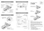


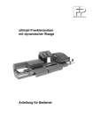

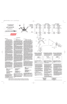


![[mailcredit / ENG] User Manual](http://vs1.manualzilla.com/store/data/005957121_1-8f833d5244dc8652c61044097905507f-150x150.png)