1
1 CCR 301-25
Colorado State Board of Education
Department of Education
Adopted:
1 Colorado Code of Regulations 301-25
11-21-72, with numerous subsequent amendments temporary regulation amendments 2-1678 and 5-10-78, repealed and readopted 1-4-79, amended 8-9-79, 10-4-79, 1-10-80, 3-13-80,
4-10-80, 10-9-80, 8-12-82, 9-13-84, 7-9-87, amended 7-14-88, 6-10-93.
Attorney General Opinions: 2-23-78, 1-15-79, 7-17-87, 7-25-88, 6-17-93.
Statutory Authority: 22-51-108, 22-2-107 (1)(c) and 42-4-613 (1) (2) (3), C.R.S.
COLORADO MINIMUM STANDARDS GOVERNING
SCHOOL TRANSPORTATION VEHICLES
2251-R-1.00
Statement of Basis and Purpose.
The statutory authority for the Amendments of 2251-R-2.00 through 107.00 the Colorado
Minimum Standards Governing School Transportation Vehicles (hereinafter "these rules"),
adopted by the State Board of Education on June 10, 1993 is found in sections 22-51-108
and 42-4-613 (1) (2) (3), C.R.S.
The purpose of this Amendment is to establish minimum standards for school transportation
vehicles purchased for use in Colorado. These standards are necessary to improve the safety
of the children riding the buses and the mechanical efficiency of the bus. The new standards
meet or exceed the national recommended minimum standards and utilize state-of-the-art
industry advances.
2251-R-2.00
FMVSSFederal Motor Vehicle Safety Standards
49 C.F.R. Part 571, Revision 1986
National Highway Traffic Safety Administration
U.S. Department of Transportation
SAESociety of Automotive Engineers, Inc.
Standards, Revision 1986
400 Commonwealth Drive
Warrendale, PA 15096
ULUnderwriters Laboratories, Inc.
Standard 299-82, Revision March 1985
1 CCR 301-25
333 Pfingsten Road
Northbrook, IL 60062
FED. SPEC.Federal Specification TT-C-520b
Revision February 1973
General Services Administration
Specification and Consumer Information
Distribution Center
Building 197
Washington, D.C. 20407
NSSBNational Standards for School Buses, Revision 1990
Recommendations of the Eleventh National Conference on
School Transportation, issued by the National Safety Council
444 North Michigan Avenue
Chicago, Illinois 60611
NBSNational Bureau of Standards
Voluntary Product Standard 1-83, Revision May 1984
Office of Standards Reference Materials
Washington, D.C. 20234
SAHSStandard Alphabets for Highway Signs - Series B
Federal Highway Administration - Revision April 1984
U.S. Government Printing Office
Washington, D.C. 20234
NFPANational Fire Protection Association
Volume 2, National Fire Codes, Revision 1985
Batterymarch Park, Quincy, MA 02269
For information regarding how the incorporated material may be obtained or examined, contact:
Colorado Department of Education
School Transportation Unit
201 East Colfax Avenue, Room 209
Denver, CO 80203
2251-R-3.00
3.01
3.02
Responsibility of Suppliers.
School transportation vehicle dealers distributors, and manufacturers each have a
responsibility to comply with these rules after the effective date of these rules, October 1,
1993.
Dealers, distributors, or manufacturers which supply school transportation vehicles for use
1 CCR 301-25
in the State of Colorado which do not meet the specifications herein stated shall be notified
of noncompliance and a general notice will be sent to all school districts and school
transportation operations within the State of Colorado advising that equipment supplied by
such dealer, distributor, or manufacturer is not in compliance with these rules, October 1,
1993.
3.03
2251-R-4.00
If a dealer, distributor, or manufacturer has been notified of non-compliance in accordance
with subsection 3.02 and replaces or modifies the equipment to meet these rules, October 1,
1993, a notification of compliance will be issued from the Colorado Department of
Education within 30 days after proof of compliance.
Effective Date of Specification.
4.01
School transportation vehicles manufactured on or after the effective date of these rules,
October 1, 1993, for the purpose of transporting Colorado school children shall meet or
exceed these minimum standards contained herein.
4.02
School transportation vehicles manufactured before the effective date of these rules, which
have been used exclusively for the purpose of transporting school children and which met or
exceeded the Colorado Standards at the time, may continue in use.
4.03
Only used buses manufactured after January 1, 1978, may be purchased, leased, or
contracted, for the purpose of transporting Colorado school children. These buses must have
met Colorado minimum standards in effect at the time of manufacture.
2251-R-5.00
5.01
School Transportation Vehicle Definitions. Section 42-1-102(69), C.R.S.
"School Bus" means every motor vehicle which is owned by a public or governmental
agency and operated for the transportation of children to or from school or which is
privately owned and operated for compensation but it does not include informal or
intermittent arrangements, such as sharing of actual gasoline expense or participation in a
car pool, for the transportation of children to or from school.
A School Bus shall be a motor vehicle with motive power, built to school bus standards,
designed for carrying passengers, which at any time would be used to carry school children,
students, and school personnel, providing that such transportation is sponsored and
approved by the local board of education or school governing agency. Vehicles that only
carry school children along with other passengers as part of the operation of a common
carrier under the jurisdiction of Interstate Commerce Commission and Public Utilities
Commission are not included within the definition of school bus.
5.02
TYPE A--Type "A" school bus is a conversion or body constructed upon a van-type
compact truck or a front-section vehicle chassis, with a gross vehicle weight rating of 10,000
pounds or less, designed for carrying passengers.
5.03
TYPE B--Type "B" school bus is a conversion or body constructed and installed upon a van
1 CCR 301-25
or front-section vehicle chassis, or stripped chassis, with a gross vehicle weight rating of
more than 10,000 pounds, designed for carrying passengers. Part of the engine is beneath
and/or behind the windshield and beside the driver's seat. The entrance door is behind the
front wheels.
5.03 (a)
Vans or other vehicles adapted for school transportation use are not acceptable
without modifications of sides and roof for added structural strength. Vehicles
shall meet all current applicable FMVSS.
5.04
TYPE C--Type "C" school bus is a body installed upon a flat back cowl chassis with a gross
vehicle weight rating of more than 10,000 pounds, designed for carrying passengers. All of
the engine is in front of the windshield and the entrance door is behind the front wheels.
5.05
TYPE D--Type "D" school bus is a body installed upon a chassis, with the engine mounted
in the front, midship, or rear, with a gross vehicle weight rating of more than 10,000 pounds,
designed for carrying passengers. The engine may be behind the windshield and beside the
driver's seat; it may be at the rear of the bus, behind the rear wheels, or midship between the
front and rear axles. The entrance door is ahead of the front wheels.
5.06
Small vehicle shall be a motor vehicle with motive power, which does not meet the
requirements of a Type A, B, C, or D school bus, and which shall not transport more than
the manufacturer's designated capacity. These vehicles shall meet or exceed FMVSS and
sections 59.01(a), 59.03 and 59.04 of these rules which at any time would be used to carry
school children, students and school personnel; provided that such transportation service is
sponsored and approved by the local board of education or school governing agency. The
preceding definition is not intended to include private motor vehicles used exclusively to
carry members of the owner's household.
5.07
Activity bus shall be a motor vehicle with motive power, designed for carrying passengers
meeting or exceeding the Colorado Minimum Standards Governing School Transportation
Vehicles except Sections:
2251-R-16.00
Color: Chassis
53.00 Capacity
54.00 Color - body
77.00 Stop Arm Signal
And the following Subsections:
2251-R-63.01
"SCHOOL BUS" Identification
63.02 School name
63.04 Vehicle numbering
63.06 "STOP ON FLASHING RED" Lettering
67.07 (a-g) School bus alternating flashing warning signal lamps
74.01 Seating design and construction
74.05 Seating material
The activity bus shall be used to carry school children, students and school personnel
1 CCR 301-25
exclusively to and from school related activities or events, provided that such transportation
is sponsored and approved by the local board of education. The activity bus shall travel
from one location to a second location without stopping to load or unload passengers or
control traffic on a public highway. The preceding definition is not intended to preclude the
use of school buses on school related activities or events.
2251-R-6.00
5.07 (a)
The body shall bear the words "ACTIVITY BUS" in letters at least 8 inches
high on both the front and rear. The lettering shall be placed as high as
possible without impairment of its visibility. Lettering shall conform to SAHS.
5.07 (b)
All activity bus seat design, attachment, construction, and material shall meet
all manufacturer's standard coach (non-school bus) seating requirements or
FMVSS 222.
5.07 (c)
Activity buses shall bear name of school or company on each side at least 5
inches in height.
Testing and Certification.
6.01
Chassis manufacturers shall provide certification to the Colorado Department of Education
that their product(s) meet these rules and all applicable FMVSS standards. Written
certification shall be provided 30 days before or after July 1, of each calendar year.
6.02
School bus body manufacturers shall provide certification to the Colorado Department of
Education that their product(s) meet or exceed these rules and all applicable FMVSS in
effect at the time of manufacture. Written certification shall be provided 30 days before or
after July 1 of each calendar year. Body manufacturers shall record and report to CDE the
test results called for in Section 55 - Construction, of these rules. All school bus bodies
shall meet applicable FMVSS and compliance with these standards shall be certified by the
body manufacturer by the attachment of a plate or decal.
6.03
It will be the district's responsibility to ascertain whether all school buses purchased, leased,
or under contract to the district meet all specifications of these rules. This verification
should be obtained at the time of delivery, in addition to the statement of compliance in the
purchase bid, contract for or lease agreement.
6.04
When selling a school bus, it is the district's responsibility to eliminate the district's name
from the sides of the bus.
2251-R-7.00
7.01
Chassis and Body Delivery Requirements.
The chassis manufacturer shall provide the following materials and information for direct
delivery to the customer:
7.01 (a)
Line set tickets for each individual unit.
7.01 (b)
A copy of the pre-delivery service performed and verified by a checkout form
for each individual unit.
1 CCR 301-25
7.01 (c)
Warranty book and statement of warranty for each individual unit.
7.01 (d)
Service manual for each individual unit or identical units.
7.01 (e)
Parts manual for each individual unit or identical units.
2251-R-8.00
Rule Number Reserved.
2251-R-9.00
Rule Number Reserved.
2251-R-10.00
Rule Number Reserved
THE BUS CHASSIS
2251-R-11.00
11.01
2251-R-12.00
Air Cleaner.
The engine intake air cleaner shall be furnished and properly installed by the chassis
manufacturer to meet engine specifications.
Axles.
12.01
The front axle and rear differential, including suspension assemblies, shall have a gross axle
weight rating at ground, at least equal to that portion of the load as would be imposed by the
chassis manufacturer's maximum gross vehicle weight rating.
12.02
Rear axle shall be full-floating type.
12.03
Rear axle shall be single-speed.
2251-R-13.00
Brakes.
13.01
All braking systems shall comply with FMVSS 105, 106, 116, 121.
13.02
Vehicles with a rated capacity of greater than 54 shall be equipped with full compressed air
brake systems.
Air brakes: The following standards apply to air brake systems:
13.03
13.03 (a)
Compressors: On buses using full compressed air brakes for service,
emergency, and parking brakes, the compressor shall be a standard production
model with a minimum 12 cubic foot per minute displacement.
13.03 (b)
Three reservoirs or chambers (wet, primary, secondary) with a total capacity
which is equal to or greater than 12 times the total volume of all brake actuators
at full travel.
13.03 (c)
Moisture ejection valve: An automatic heated, moisture ejection valve or air
drying system shall be properly installed. This is made to automatically eject
moisture, sludge, and/or foreign matter and maintain clean, dry air lines.
1 CCR 301-25
13.03 (d)
Control requirements: Control valve of the parking brake system shall be
designed and constructed to conform with the following:
13.03 (d)(1) The parking brake control valve shall be visible to the driver and shall be
mounted on the dash panel within 15 inches to the right of the steering
column.
2251-R-14.00
Bumper, Front.
14.01
Front bumper on all Type A, B and C school buses shall be furnished by the chassis
manufacturer.
14.02
Front bumper of Type D school buses shall be furnished by the body manufacturer.
14.03
Front bumper shall be at least 3/16 inch thick of pressed steel channel, one piece
construction or optional 3-piece breakaway construction and a minimum of eight inches
wide (high).
14.04
Front bumper shall be of extended design to offer maximum protection of fender lines
without permitting snagging or hooking.
14.05
Front bumper shall be attached to the frame and extend forward of grille, head lamps,
fender, or hood sections to provide maximum protection.
14.06
Front bumper shall be of sufficient strength to permit pushing of vehicle of equal weight
without permanent distortion to bumper, chassis, or body.
2251-R-15.00
15.01
2251-R-16.00
Clutch.
Clutch torque capacity shall be commensurate with or greater than the maximum rated
engine torque output.
Color: Chassis.
16.01
Frame and bumper shall be painted black.
16.02
Cowl and fenders shall be painted National School Bus Yellow as defined in NSSB.
16.03
Hood shall be painted non-reflective National School Bus Yellow as defined in NSSB.
16.04
Any wheels and rims that are not iron-gray or galvanized shall be painted black.
2251-R-17.00
17.01
Cooling System.
The cooling system fan shall be heavy-duty reinforced type. Fan may be controlled by
thermostatically actuated clutch.
1 CCR 301-25
17.02
The cooling system radiator shall be of sufficient capacity to cool the engine at all speeds in
all gears. Thermostatic controls shall be high temperature type.
17.03
On all chassis requiring hoses or extensions to fill radiators, the hose or extensions shall be
so designed to permit adding of coolant without trapping air.
17.04
Permanent ethylene-glycol base or environmentally safe equivalent anti-freeze shall be
provided by chassis manufacturer to protect the cooling system to -30 degrees Fahrenheit (F)
when tested at normal engine temperature and shall not be diluted by body company.
17.05
Type C and D Buses equipped with an automatic transmission, shall have a heavy-duty
cooling system with increased capacity in the radiator, fan, and other necessary components,
to provide for the additional cooling required by the automatic transmission. External oil
filter on oil return line between cooling system and transmission shall be provided.
17.06
Cooling system shall be equipped with a coolant recovery system.
17.07
Cooling system shall be equipped with a visual fluid level indicator.
2251-R-18.00
18.01
2251-R-19.00
19.01
2251-R-20.00
Drive Shaft.
Each drive shaft or section thereof shall be equipped with adequate metal guard or guards to
prevent whipping through floor or dropping to ground if broken.
Electrical System.
The electrical system {including battery(ies) and alternator} shall be commensurate with all
electrical needs of the bus, including accessories. Alternator shall be capable of producing a
minimum of 50% of its maximum rated output at the engine manufacturer's recommended
idle speed.
Exhaust System.
20.01
Exhaust pipe, muffler, and tail pipe shall be outside the passenger portion of the bus body
and attached to chassis. Exhaust back pressure shall not exceed engine manufacturer
maximum requirement.
20.02
Muffler shall be heavy-duty truck type of aluminized or stainless steel, or ceramic coated to
offer maximum resistance to corrosion or oxidation.
20.03
Tail pipe shall be constructed of seamless or electrically welded tubing of 16 gauge steel or
equivalent, and shall extend at least five inches beyond chassis frame with sufficient length
to reach the bumper, but not to extend beyond rear bumper. Where frame extends to rear
bumper, 5 inch extension not required. Type A school buses may have exhaust pipe routed
to right or left behind rear axle.
Diameter of tail pipe shall not be reduced after it leaves muffler.
20.04
20.05
The rear end of tail pipe must be located at least 20 inches to the right or left of the
centerline of the chassis.
1 CCR 301-25
20.06
2251-R-21.00
Exhaust system shall be insulated from fuel tank and fuel tank connections by securely
attached metal shield at any point where it is 12 inches or less from the fuel tank or fuel tank
connections. (Gasoline engines only)
Fenders, Front.
21.01
Total spread of outer edges of front fenders measured at fender line shall exceed total spread
of front tires when front wheels are in straight ahead position.
21.02
Front fenders shall be braced and free from any body attachment. Trailing edge of front
fender shall extend to bottom of front body section. Fender extensions are acceptable.
2251-R-22.00
Frame.
22.01
Frame shall be designed to correspond with or exceed standard practice performance criteria
for truck of same general load specifications used for severe service.
22.02
Frame side members shall be one-piece construction between front hanger of front spring,
and rear hanger of rear spring.
22.03
Extension of frame lengths shall not be for the purpose of extending wheelbase. All frame
attachments beyond the wheelbase must receive prior approval in writing from the Colorado
Department of Education. Approval(s) will be granted only after receiving certifications
that extensions equal or exceed strength of solid frame rail sections and are warranted for 10
years by manufacturers.
22.04
No holes shall be permitted in the chassis rails except those drilled at the chassis plant or
authorized by the chassis manufacturer.
22.05
Welding to frame side rails which is necessary by design to strengthen, modify or alter basic
vehicle configuration shall be performed and guaranteed by the body or chassis
manufacturer making the modification.
2251-R-23.00
23.01
Fuel Tank.
All fuel tank specifications shall conform with FMVSS 301 and provisions outlined below:
23.01 (a)
Fuel tank shall be filled and vented entirely outside the passenger compartment.
23.01 (b)
Fuel filter with replaceable element shall be installed between fuel tank and
engine.
23.01 (c)
Drain plug of at least 1/4 inch diameter shall be located in the lowest level of
the tank.
23.01 (d)
Engine supply line shall not be mounted below fuel tank.
1 CCR 301-25
23.01 (e)
2251-R-24.00
24.01
2251-R-25.00
25.01
2251-R-26.00
26.01
Heating System.
Engine design shall provide inlet and outlet holes in accessible locations for attachment of
bus heating system water lines. Heater outlets shall be of sufficient size to accommodate
circulation of all coolant with no reduction of coolant lines.
Horn.
Bus shall be equipped with dual horns of standard make, each horn capable of producing
complex sound in band of audio frequencies from 250 to 2000 cycles per second and having
total sound level of 110 decibels within these frequency limits when measured at point on
axis of horn, three feet from exit of horn.
Instruments and Instrument Panel.
Chassis shall be equipped with the following non-glare instruments and gauges. Lights in
lieu of gauges are not acceptable.
26.01 (a)
Standard speedometer with seven digit odometer,
26.01 (b)
Voltmeter with a graduated scale to 16 volts.
26.01 (c)
Oil pressure gauge.
26.01 (d)
Water temperature gauge.
26.01 (e)
Fuel gauge.
26.01 (f)
Upper-beam headlamp indicator.
26.01 (g)
Tachometer. The tachometer is not required for Type A and B school buses.
26.01 (h)
Left and right turn-signal indicator.
26.01 (i)
Chassis with air brake systems shall be equipped with a visible gauge and
audible low-pressure indicator to warn driver if air pressure in brake system
falls below 60 PSI. (see BRAKES, Section 13)
26.01 (j)
Chassis with air brake systems shall have a labeled visual indicator of park
brake application visible to driver.
Chassis with a hydraulic assist-brake system shall be equipped with warning
signals, readily audible and visible to the driver, that will provide continuous
warning in the event of a loss of fluid flow from primary source or loss of
electric source powering the back-up system.
26.01 (k)
26.02
The actual draw or usable capacity shall be a minimum of 83% of the tank's
rated capacity.
All instruments shall be easily readable by driver and accessible for maintenance.
1 CCR 301-25
2251-R-27.00
27.01
2251-R-28.00
28.01
2251-R-29.00
29.01
2251-R-30.00
30.01
2251-R-31.00
Lamps and Signals.
All lamps and their installation shall conform to current standards and recommended
practices of applicable SAE and FMVSS standards.
Openings.
All openings made by chassis manufacturer in floorboard and fire-wall shall be sealed by the
chassis manufacturer to prevent gases from entering driver's compartment. Boot for the
accelerator pedal, gear shift, and parking brake, when required, shall be supplied by the
chassis manufacturer.
Overall Length.
Overall length of bus shall not exceed 40 feet {Section 42-4-404(2), C.R.S.}.
Power or Gradeability.
The gross vehicle weight of any school bus shall not exceed 165 pounds per certified net
horsepower of the engine at manufacturer's recommended maximum revolutions per minute
(RPM).
Retarder (optional)
31.01
Rule Number Reserved
31.02
School buses equipped with electro-magnetic retarder(s) shall have increased electrical
system capacity commensurate with the needs of the retarder system.
31.03
Pilot lights shall indicate when retarder is in operation.
2251-R-32.00
Springs.
32.01
Capacity of suspension assemblies shall be commensurate with chassis manufacturer's gross
vehicle weight rating.
32.02
If leaf-type rear springs are used, they shall be of progressive type.
2251-R-33.00
Steering Gear Assembly.
33.01
All school bus chassis in all passenger capacities shall be equipped with heavy-duty, trucktype integral power steering. Power steering components shall be compatible with the GVW
rating for each capacity as shown in chassis manufacturer's literature.
33.02
No changes shall be made in steering apparatus which are not approved and guaranteed by
chassis manufacturer.
1 CCR 301-25
33.03
There shall be a clearance of at least two inches between steering wheel and any other
surface or control.
33.04
Chassis manufacturers shall provide and cover steering wheel column with a temporary
plastic covering or equivalent, in order to provide protection from precipitation from time of
manufacture until body is mounted.
2251-R-34.00
Tires and Rims.
34.01
Minimum tire and rim sizes shall be in accordance with FMVSS 120.
34.02
Dual rear tires shall be provided on Type B, C, and D school buses.
34.03
All wheels shall be one piece disc type. Split or multi-piece rims are not acceptable.
2251-R-35.00
35.01
2251-R-36.00
36.01
2251-R-37.00
37.01
2251-R-38.00
38.01
Tow Hooks.
Two heavy duty tow hooks or two eyes on Type D buses shall be furnished and factory
installed, except on Type A and B buses. Hooks shall not extend beyond the front bumper
on any school bus.
Transmission.
Manual type transmission shall be synchromesh for forward gear ratios 2nd and above.
Undercoating.
Chassis manufacturer shall coat undersides of steel or metallic front fenders with rustproofing compound for which compound manufacturer has issued notarized certification of
compliance to chassis builder that compound meets or exceeds all performance and
qualitative requirements of Fed. Spec. using modified test.
Wiring.
General--all wiring shall conform to current applicable recommended practices of SAE.
38.01 (a)
38.02
All wiring shall use a standard color and number coding and each chassis shall
be delivered with a wiring diagram that coincides with the wiring of the
chassis.
Chassis manufacturer shall install a readily accessible terminal strip or plug on the body side
of the cowl, or at an accessible location in the engine compartment of vehicles designed
without a cowl, that shall contain the following terminals for the body connections:
(1)
(2)
(3)
(4)
(5)
(6)
main 100 amp body circuit
tail lamps
right turn signal
left turn signal
stop lamps
back up lamps
1 CCR 301-25
(7)
instrument panel lights
38.02(a)
Factory terminal strip from chassis manufacturer on Type A bus will be
acceptable.
2251-R-39.00
Rule number reserved
2251-R-40.00
Rule number reserved
2251-R-41.00
Rule number reserved
2251-R-42.00
Rule number reserved
2251-R-43.00
Rule number reserved
2251-R-44.00
Rule number reserved
2251-R-45.00
Rule number reserved
2251-R-46.00
Rule number reserved
2251-R-47.00
Rule number reserved
2251-R-48.00
Rule number reserved
2251-R-49.00
Rule number reserved
THE BUS BODY
2251-R-50.00
Aisle.
50.01
Minimum aisle clearance between seats shall be 12 inches at seat level and 15 inches at top
of seats. This includes the aisles to all emergency doors.
50.02
On forward control (front engine) Type D buses, the aisle passage area shall not be less than
12 inches, measured from floor level up, between engine cover and any other object. Hold
down fastening devices used on engine cover shall be designed to prevent hooking or
catching on shoes or clothing.
2251-R-51.00
Battery.
51.01
Battery and all cable required to complete circuits without splicing, even when drawer is
extended for battery servicing, shall be provided by the chassis manufacturer and mounted
for delivery to body plant.
51.02
Body manufacturer shall provide, at customer option, a drawer-type pull out tray to facilitate
servicing or removal of battery(ies). The battery(ies) shall be enclosed by a vented
compartment constructed of mill-applied zinc steel provided with drain ports, hold down
carrier mounted so as to avoid blocking filler ports and latching device to prevent accidental
1 CCR 301-25
opening. Under-coating shall be provided and applied to battery box. Battery tray is to be
equipped with a safety device to keep tray from sliding completely out to prevent battery
from being dropped. Battery compartment shall be labeled with the word "Battery".
2251-R-52.00
Bumper, Rear.
52.01
Rear bumper shall be of pressed steel channel or equivalent material, at least 3/16-inch thick,
and shall be a minimum of 8 inches wide (high) on Type A buses, and shall be a minimum
of 9 1/2" wide (high) on Type B, C, and D buses, and of sufficient strength to permit being
pushed by another vehicle without permanent distortion.
52.02
Rear bumper shall be wrapped around back corners of bus and extend forward at least 12
inches from rear-most point of body at floor line.
52.03
Bumper shall be fastened to chassis frame side rails in such a manner as to develop full
strength of bumper section from rear or side impact. Bracing materials shall have an impact
ratio comparable to that of bumper material and shall be fastened at the ends and radii of the
bumper, attached to the side of the frame only and not to body at any point.
52.04
Rear bumper shall extend beyond rear-most part of body surface at least one inch, measured
at floor lines.
52.05
No spaces, projections, or cut-outs that will permit a hand hold or foot hold shall be
permitted.
52.06
Front ends of the bumper shall be enclosed by end caps or other protective metal or shall
have the ends rounded or tucked in and shall be free from sharp edges or projections likely
to cause injury or snagging.
52.07
A gasket, rubber or equivalent, shall be installed to close opening between the top of the rear
bumper and body metal.
2251-R-53.00
53.01
2251-R-54.00
54.01
Capacity.
Capacities and seat spacing shall conform to and be in full compliance with applicable
FMVSS.
Color.
All exterior metal shall be painted National School Bus Yellow as specified in NSSB with
the exception of those areas listed below.
54.01 (a) Lettering and numbering (black, white, or yellow for bumper area)
54.01 (b)
Bumpers (black)
54.01 (c)
Rubrails may be black or yellow at purchaser option
54.01 (d)
Background area for warning light system. (black)
1 CCR 301-25
54.01 (e)
54.02
2251-R-55.00
The roof of the bus may be painted white not to extend below the drip rails on
the sides of the body except that front and rear roof caps shall remain National
School Bus Yellow.
Reflective material may be installed on the bus. Material, if used, shall be automotive
engineering grade or better, meeting initial reflectance values in FHWA FP-85 and retaining
at least 50% of those values for a minimum of six years. Reflective materials and markings,
if used, shall include any or all of the following:
54.02 (a)
Front and/or rear bumper: may be marked diagonally 45 degrees down to
centerline of pavement with 2 inch wide strips of non-contrasting reflective
material.
54.02 (b)
Rear of bus body: may be marked with a strip of reflective National School
Bus Yellow material not to exceed 12 inches width to be applied to the back of
the bus, extending from the left lower corner of the "school bus" lettering,
across to left side of the bus, then vertically down to the top of the bumper,
across the bus on a line immediately above the bumper to the right side, then
vertically up to a point even with the strip placement on the left side, and
concluding with a horizontal strip terminating at the right lower corner of the
"school bus" lettering.
54.02 (c)
"School Bus" signs: may be marked with reflective National School Bus
Yellow material comprising background for lettering of the front and/or rear
"school bus" signs.
54.02 (d)
Sides of bus body: may be marked with reflective National School Bus Yellow
material not to exceed 12" in width, extending the length of the bus body and
located (vertically) as close as practicable to the beltline.
Construction.
55.01
All bus body construction components shall be of prime commercial quality mill applied,
zinc coated steel or material of at least equivalent strength. Such items shall include
structural members, inside panels, floor panels, and joints.
55.02
All metal surfaces that will be painted shall be (in addition to above requirements)
chemically cleaned, etched, zinc-phosphate-coated and zinc-chromate or epoxy primed or
conditioned by equivalent process. In providing for these requirements, particular attention
shall be given to lapped surfaces, welded connections of structural members, cut edges,
punched or drilled hole areas in sheet metal, closed or box sections, unvented or undrained
areas and surfaces subject to abrasion during vehicle operation.
55.03
The floor shall be at least 14 gauge mill applied zinc-coated steel sheet and shall be on one
plane. There shall be a main floor cross member of at least 10 gauge steel or equivalent
placed at each side post extending the full width of the floor plate and permanently attached.
There shall be a minimum of two intermediate floor cross members of at least 16 gauge
steel equally between the main floor cross members and permanently attached.
1 CCR 301-25
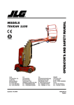
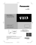
55.04
In addition to complying with the test procedures described in FMVSS 220, the body
manufacturers shall record and report the downward vertical movement of the force at 0, 25,
50, 75, and 100% of the maximum force (both loading and unloading). The expected force
deflection curve is illustrated schematically in Figure 1a. Low load nonlinearities may
indicate joint conformation; high load nonlinearities may indicate yielding instructural
members.
55.04 (a)
A second load cycle shall be performed following the procedure given in the
first paragraph.
The expected force-deflection curve is illustrated
schematically in Figure 1b. Any hysteresis following the initial shakedown
will be revealed by this second cycle.
a. First Cycle
b. Second Cycle
Figure 1. Static Load Test Load-Deflection Curves
55.05
A diagonal (racking) load test shall be performed on Type A, B, C, D school buses to assure
adequate shear stiffness and strength of the bus body. Details of the test are provided below.
A two cycle loading sequence shall be conducted following the procedure described in
Section 55.04.
55.05 (a)
Requirements: When a force equal to 1-1/2 times the GVW is applied to the
edge of the roof of the vehicle's body structure through a force application plate
as specified in (b), Test Procedures:
55.05 (a)(1) The diagonal movement of the force at any point on the application plate shall
not exceed 5 1/8 inches; and
55.05 (a)(2) Each emergency exit of the vehicle provided in accordance with FMVSS 217
shall be capable of operation as specified in that standard during the full
application of the force and after release of the force.
55.05 (b)
Test Procedures: Each vehicle shall be capable of meeting the requirements of
(1) and (2) when tested in accordance with the procedures set forth below.
1 CCR 301-25
55.05 (b)(1) The vehicle shall be supported on a rigid surface along the lower edge of the
frame or along the body sills in the absence of a frame.
55.05 (b)(2) The load shall be applied through a force application plate that is flat and rigid.
The dimensions of the plate shall be chosen to assure that the plate
edges never make contact with the vehicle skin during testing. A typical
width is 18 inches, and a typical length is 20 inches less that the length
of the vehicle's roof measured along its longitudinal centerline.
55.05 (b)(3) Place the force application plate in contact with the edge of the vehicle roof.
Orient the plate so that its flat, rigid surface is perpendicular to a
diagonal line connecting the most distant points on an interior cross
section of the vehicle. The rear edge of the plate shall be positioned
approximately 20 inches from the rear edge of the vehicle roof. A
temporary stand may be used to support the plate until a force is applied.
55.05 (b)(4) Apply an evenly distributed force in a diagonally downward direction through
the force application plate at any rate not more than 0.5 inch per second,
until a force of 500 pounds has been applied.
55.05 (b)(5) Apply additional force in a diagonally downward direction through the force
application plate at a rate of not more than 0.5 inch per second until the
force specified in (a) has been applied, and maintain this application of
force.
55.05 (b)(6) Measure the diagonal movement of any point on the force application plate
which occurred during the application of force in accordance with (5)
and open the emergency exits as specified in (a)(2).
55.05 (b)(7) Release all diagonal force applied through the force application plate and
operate the emergency exits as specified in (a)(2).
55.05 (c)
Test Conditions: The following conditions apply to the requirements specified
in (4).
55.05 (c)(1) Temperature: The ambient temperature is any level between 32 degrees F and
90 degrees F.
55.05 (c)(2) Windows and Doors: Vehicle windows, doors, and emergency exits are in the
fully-closed position, and latched but not locked.
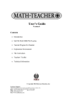
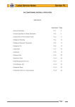
55.05 (d)
An alternative method of testing for the racking load test shall be as follows:
The racking load shall be applied along a line connecting the most distant points on a
transverse cross section of the bus interior. It produces a shear distortion of the cross
section as shown in figure 2.
A representative method of loading which employs a hydraulic jack to load a twoframe test assembly is illustrated in figure 2. The maximum jack load for the two-
1 CCR 301-25
frame assembly is determined by the following formula:
J = 2P
J - maximum jack load for two-frame test assembly
P = load/frame
where P = DVW divided by N
DVW - dynamic vehicle weight
N - total number of bus body frames
and DVW = DF x GVW
DF - dynamic factor, not less than 1.5
GVW - gross vehicle weight
Thus, for a DF = 1.5, a GVW = 22,000 pounds per foot (lbf) and N= 11, the dynamic
vehicle weight is DVW = 33,000 lbf, the load/frame is P = 3000 lbf and the maximum
jack load is J = 6000 lbf.
When a complete bus body is rack-loaded, the total load DVW must be distributed
uniformly along the bus body. This may be accomplished by mounting a series of
hydraulic jacks along the length of the bus interior. Seats may be removed to
facilitate jack mounting. The rack load will be considered to be uniformly distributed
when the variation in the hydraulic jack readings is less than 10 percent. A maximum
load the sum of all jack readings shall equal DVW.
Transverse Cross
Section
Side View
Figure 2. Arrangement of Hydraulic Jack for Rack-Loading of Two-Frame Assembly
The test may be performed on a complete bus body or on a representative section
composed of at least two complete frames (body posts plus roof bows) and floor.
Standard seats may be installed in the test section in a manner identical to that of the
full bus body. Fabrication procedures for the test assembly shall be identical to those
used in normal bus body production.
A two-cycle loading sequence shall be conducted, with intermediate and final load
and deflection readings recorded according to the procedure described.
1 CCR 301-25
The maximum deflection in line with the jack ( A, maximum) shall not exceed 4
inches. Manufacturers shall specify which testing method was used and submit
appropriate certification information as called for in 6.02.
55.06
Subfloor shall be either 5 ply nominal 5/8 inches thick plywood, or a material of equal or
greater strength and insulation R value and it will equal or exceed properties of exterior-type
softwood plywood C-D grade, as specified in NBS Product Standard 1-83. Type A vehicles
shall have nominal 1/2 inch thick plywood or equivalent material equal to or exceeding
properties listed above.
55.07
Ceiling Panels: If the ceiling is so constructed to contain lap joints, the forward panel shall
be lapped by the rear panel and the exposed edges shall be beamed, hemmed, or flanged or
otherwise treated to minimize sharp edges.
55.08
All body components shall be designed and constructed so as to avoid the entrapment of
moisture and dust.
55.09
All openings between chassis and passenger-carrying compartment made for any reason by
body manufacturer must be sealed.
2251-R-56.00
Defrosters.
56.01
A defroster system shall be installed of sufficient capacity to keep windshield area, left
frontside window to rear of driver's vision, and service door glass area free of condensation
or ice.
56.02
Adjustable 6 inch auxiliary fans may be installed to complement the defroster system used
by the manufacturer. Such fans shall be controlled individually by two-speed switches
located on control panel. Fan blades shall be covered with a protective cage.
56.03
The defrosting system shall conform to SAE Standards.
2251-R-57.00
57.01
57.02
Doors.
Service door shall be power or manually operated, under control of the driver, and so
designed to afford easy release and to prevent accidental opening. When manual lever is
used, no parts shall come together so as to shear or crush fingers.
Service door shall be located on right side of bus opposite driver and within driver's direct
view.
57.03
Service door shall have minimum horizontal opening of 24 inches and minimum vertical
opening of 68 inches. Type A buses shall have a minimum door opening area of 1200
square inches.
57.04
There shall be no door to the left of the driver on Type C or D buses. Type A and B buses
may be equipped with chassis manufacturer's standard door.
57.05
Service door may be of split type, folding type, or section type. Split type door includes any
sectional door which divides and opens inward or outward. If one section of split type door
1 CCR 301-25
opens inward and other outward, front section shall open outward. The door shall be
equipped with a flexible material on the vertical closing edge(s), designed to protect
passengers' fingers.
57.06
All door glass shall comply with FMVSS 205. Glass in service door shall provide
maximum area of visibility for operation of bus.
57.07
Power operated doors shall be equipped with a separate manual emergency release, readily
accessible in the door area above or to the side of the service door or on dash, so that the
door may be opened in the case of emergency. The release shall be plainly labeled with
instruction for use.
57.08
There shall be a head bumper pad installed on the inside at the top of the entrance door.
This pad shall be approximately 3 inches wide (high), at least 1 inch thick, and extend across
the entire top of the entrance door opening.
2251-R-58.00
58.01
Emergency Exits
Emergency door(s) shall be equipped with a 3-point latch mechanism. Type A buses shall
be equipped with the standard latch. Emergency door latch shall be equipped with suitable
electric plunger-type switch connected with buzzer located in driver's compartment. Switch
shall be enclosed in metal case and wires leading from switch shall be concealed in bus
body. Switch shall be so installed that plunger contacts farthest edge of slide bar in such
manner that any movement of slide bar will immediately close circuit on switch and activate
buzzer. A separate interior handle shall be provided to pull the door shut from the inside.
58.01(a)
When flip-up seat is located next to emergency door, the inside door handle
must be enclosed or protected by a safety guard to prevent accidental opening.
58.02
Exterior door handle shall be of permanent hitch-proof design and mounted with enough
clearance to permit opening without touching door surface and may be equipped with a lock
which will not prevent opening from inside.
58.03
All emergency door openings shall be completely weather stripped.
58.04
Operation instructions for opening of door shall be lettered or decaled on the inside of the
emergency door.
58.05
Emergency door shall bear words "EMERGENCY EXIT" both inside and outside in
letters at least 2 inches high. Words shall be placed directly above the door or on the upper
portion of the door.
58.06
On all buses except rear engine transit school buses (Type D), an emergency door shall be
located in the rear of the bus body and centered with respect to the body. Door shall have a
minimum horizontal opening of 24 inches and minimum vertical opening of 48 inches
measured from floor level. Rear emergency door shall be hinged on right side and shall
open outward.
1 CCR 301-25
58.07
Rear emergency door shall contain upper and lower glass panels which comply with
FMVSS 205. Glass in emergency door shall provide maximum area of visibility for safe
operation of bus.
58.08
There shall be a head bumper pad installed over the emergency door on the inside of the bus
body. This pad shall be approximately 3 inches wide (high), at least 1 inch thick, and extend
across the entire top of the emergency door opening. Padding shall be of the same materials
as the padding used over the service door.
58.09
Side emergency door: If engine or storage compartment is so located as to make it
impossible to place door in center of rear end, the emergency door shall be located in the
rear half of the left side of the bus body. The door shall not be located to reduce size of
opening by wheelwell. The door shall be hinged on the front side.
58.10
Rear emergency window: If engine or storage compartment is so located as to require a side
emergency door, an emergency window shall be installed in the rear of the bus and shall be
no smaller than 16 inches in height and 54 inches in width.
58.10 (a)
The emergency window shall meet FMVSS 205. Glass shall be tempered
unless specified laminated by the purchaser.
58.10 (b)
Emergency window shall be hinged from top and provided with a hold open
control to insure against accidental closing during an emergency.
58.10 (c)
Emergency window in rear shall be equipped with latch on the inside and with
a handle of hitch proof design which will permit opening from the outside.
58.11
All designated emergency windows shall bear words "EMERGENCY EXIT" in letters at
least 2 inches high both inside and outside the window. Lettering shall be placed no more
than three inches directly above window.
58.12
All designated emergency windows shall be equipped with a buzzer. When not fully
latched, it shall activate a signal audible to the driver.
58.13
2251-R-59.00
59.01
Ignition interlock for the vandal locks shall conform to FMVSS.
Emergency Equipment.
The bus shall be equipped with at least one pressurized 5-pound dry-chemical fire
extinguisher of a type approved by UL, with a total rating of not less than 2A10BC. The
operating mechanism shall be sealed with a type of seal that will not interfere with use of the
fire extinguisher.
59.01 (a)
59.02
The small vehicle shall be equipped with one securely mounted 2 1/2 pound
dry chemical fire extinguisher of a type approved by UL, with a minimum
rating of 1A10BC.
Fire extinguisher shall be mounted in the extinguisher manufacturer's bracket (automotive
type) and located in the driver's compartment in full view of and readily accessible to the
driver. A pressure gauge shall be so mounted on the extinguisher as to be easily read
1 CCR 301-25
without removing the extinguisher from its mounted position.
59.03
First Aid Kit(s): The bus and small vehicle shall carry a first aid kit or kits which shall
either be mounted securely in full view or the location plainly indicated by appropriate
markings, in the drivers compartment. The kit(s) shall be mounted in such a manner that
they can be removed if necessary. Small vehicles and buses with a manufacturer's rated
seating capacity of 36 or less shall be equipped with one 24 unit kit. Buses rated more than
36 capacity shall be equipped with two 24 unit kits.
Contents of the 24 unit First Aid Kit:
Item
Unit(s)
Adhesive Tape................................................................................................................... 1
1" adhesive bandage ......................................................................................................... 2
2" bandage compress......................................................................................................... 1
3" bandage compress......................................................................................................... 1
4" bandage compress......................................................................................................... 1
3" x 3" plain gauze pads.................................................................................................... 1
Gauze roller bandage 2" wide ........................................................................................... 2
Plain absorbent gauze - 1/2 square yard............................................................................ 4
Plain absorbent gauze - 24" x 72" ..................................................................................... 3
Triangular bandages.......................................................................................................... 4
Scissors, tweezers.............................................................................................................. 1
Space rescue blanket ........................................................................................................ 1
Latex disposable gloves, pair ..................................... . . . . . . . . . . . . . . . . . . . . . . . . . . . . 1
CPR mask or mouth to mouth airway ........................... . . . . . . . . . . . . . . . . . . . . . . . . . . 1
Moisture and dustproof kit of sufficient capacity to contain materials of the Colorado first
aid kit ................................................................................................................................ 1
59.04
Emergency Reflectors (Section 42-4-227, C.R.S.)
59.04 (a)
2251-R-60.00
All buses and small vehicles shall carry three (3) emergency triangle reflectors
in compliance with FMVSS 125, contained in a securely mounted case.
Floor Coverings.
60.01
Floor in underseat area, including tops of wheel housings, driver's compartment, and
toeboard shall be covered with fire-resistant rubber floor covering or equivalent having a
minimum overall thickness of .125 inch.
60.02
Floor covering in aisle shall be aisle-type fire-resistant rubber or equivalent, non-skid, wear
resistant, and ribbed. Minimum overall thickness shall be .1875 inch measured from tops of
ribs.
60.03
Floor covering must be permanently bonded to floor and must not crack when subjected to
sudden changes in temperature. Bonding or adhesive material shall be waterproof and shall
be of type recommended by manufacturer of floor-covering material. All seams must be
sealed with waterproof sealer.
Cove molding shall be used along the side walls and rear corners and all floor seam
60.04
1 CCR 301-25
separations shall be covered with durable metal stripping.
60.05
The entrance step treads, including the edge at floor level, shall be of the same quality as the
aisle material. Step treads shall have an integral white nosing of 1-1/2 inch or more or use
diagonal stripes. Treads shall be permanently bonded to the metal steps and sealed to
prevent water from getting underneath the step tread.
60.06
A secured and insulated plate shall be provided to access fuel tank sending unit. Type A
buses are exempt.
2251-R-61.00
61.01
2251-R-62.00
62.01
Fuel Fill Cap Cover.
The fuel fill cap opening in the body skirt shall be equipped with a hinged cover held closed
by a spring or other conveniently operated device. Type A vehicles are exempt.
Heating System.
All school buses shall be equipped with two or more hot water heaters capable of delivering
water to the system at a rate of six gallons per minute using an ambient temperature of 0
degree F to +10 degrees F and maintaining passenger compartment temperature of 50
degrees F. One of the heaters shall be located in the rear half of the bus on or behind the
rear wheel axle line.
62.01(a)
Lift equipped buses may place the rear heater under the last row of seats.
62.02
Buses shall be equipped with front heater(s) and integrated defroster system of capacity to
provide heat for the front part of the bus (including driver' compartment) and to keep
windshield area, service door glass, driver's left glass area, and stepwell clear of moisture,
ice and snow.
62.03
Hot water heaters shall bear the name plate rating in accordance with NSSB.
62.04
62.05
Two speed switches shall operate all heater fans independently.
Heater cores and fans shall be completely encased but designed to permit servicing heater
assembly by removing all or part of case.
62.06
Heater hose installation in the engine compartment shall include two shut-off valves able to
shut off coolant completely when necessary.
62.06 (a) One mounted between the water pump outlet and heater hose connection.
62.07
62.06 (b)
One mounted between the motor block and the return heater hose connection.
62.06 (c)
Heater hoses shall be adequately supported to guard against excessive wear due
to vibration. Hoses shall not rub against the chassis, body or other edges.
The body manufacturer shall add the required amount of permanent ethylene glycol base or
environmentally safe equivalent anti-freeze after heaters have been connected to protect
cooling system of bus to -30 degrees F tested at normal engine temperature.
1 CCR 301-25
62.08
2251-R-63.00
There shall be a heater water flow regulating valve installed for convenient operation by the
driver.
Identification.
63.01
Body shall bear words "SCHOOL BUS" in black letters at least 8 inches high on both front
and rear of body. Lettering shall be placed as high as possible without impairment of its
visibility. Lettering shall conform to SAHS.
63.02
School buses shall bear name of school district or company on each side in black, standard
unshaded letters, 5 inches in height. If there is insufficient space due to the length of the
name of the school district, terms such as community, consolidated, and district may be
abbreviated.
63.03
The manufacturer's rated pupil seating capacity shall be printed to the left of the entrance
door on the lower skirt in 2 inch characters. The word capacity may be abbreviated.
(Example: Cap. 48) The capacity shall also be shown on the inside upper portion of the
entrance door or inside above the windshield.
63.04
The numbering of individual buses for identification purposes is permissible.
63.05
Lettering and numerals shall be painted or may be pressure sensitive marking of similar
performance quality.
63.06
"STOP" shall be printed on the rear of the bus in letters at least 8 inches high. "ON
FLASHING RED" shall be printed below "STOP," in letters at least 5 inches high.
Letters shall be placed in area(s) visible to the approaching motorist.
63.07
The school district logo may be placed above the side window dripline.
63.08
Only signs and lettering specifically permitted by state law or regulation, and any marking
necessary for safety and identification, shall appear on the outside of the bus.
63.08 (a)
2251-R-64.00
64.01
Advertising, approved by the local school board, may appear only on the
side(s) of the bus in the following areas:
1.
The signs shall be below the seat level rub rail.
2.
The signs shall be at least three inches from any required lettering, lamp,
wheelwell, or reflector behind the service door or stop signal arm.
3.
The signs shall not extend from the body so as to allow a handhold or
present a danger to pedestrians.
4.
The signs shall not interfere with the operation of any door, window or
other device.
5.
The signs shall not be placed on side emergency door(s).
Inside Height.
Inside body height shall be 72 inches or more, measured metal to metal at any point on
longitudinal center line from front vertical bow to rear vertical bow. Type A school buses
1 CCR 301-25
shall have 62 inches or more inside height, measured metal to metal.
2251-R-65.00
65.01
2251-R-66.00
66.01
2251-R-67.00
Insulation.
Bus body shall be fully insulated in the roof including roof bows and all body panels.
Insulation 1 inch minimum thickness shall be of fiber-glass or equal and shall be fire
resistant.
Interior.
Interior of bus shall be free of all projections likely to cause injury.
Lamps and Signals.
67.01
All lamps, signals, reflectors and their installation shall conform to standards and
recommendations of SAE and meet FMVSS.
67.02
Tail and stop (brake) lamps:
67.02 (a)
Bus shall be equipped with four combination red stop/tail lamps. Two
combination stop lamps shall have a lens diameter of at least 7 inches or 38.48
square inches, and shall have light intensity at least equal to Class A, Type I
turn-signal units as established by SAE. Two combination tail lamps shall
have a lens diameter of at least 4 inches.
67.02 (b)
If the bus is equipped with a retarder, the four stop lamps shall be illuminated
when the retarder is activated.
67.02 (c)
There shall not be lettering, symbols or arrows, except manufacturer's
markings, on the lens.
67.03
License plate lamp: Bus shall be equipped with rear license plate illuminator. This lamp
may be combined with one of the tail lamps.
67.04
Interior lamps: Interior lamps shall be provided which adequately illuminate aisle. A
separate lamp shall be provided in stepwell.
67.05
Back-up lamps: Back-up lamps of 7 inch or 38.48 square inches, minimum diameter shall
be provided.
67.06
Turn signal lamps:
67.06 (a)
The bus shall be equipped with two amber turn signals in front and two amber
turn signals in the rear. Both front and rear signals shall be at least 7 inches in
diameter and meet the specifications of SAE.
67.06 (b)
There shall not be lettering, symbols or arrows, except manufacturer's
markings, on the lens.
1 CCR 301-25
67.07
67.06 (c)
The four-way hazard switch shall activate the turn signal lamps only. This
operation shall be independent of any other light system.
67.06 (d)
Type C and D buses shall have turn signal lamp(s) mounted with its axis
substantially parallel to longitudinal axis of vehicle. Rear lamps shall be
mounted as near to the right and left side of bus as possible but in no case shall
outer edge of lamps be more than 10 inches from outer body width line. They
shall be mounted below rear windows but in no case shall distance from top
edge of lamp to lower edge of window exceed 10 inches. Front amber lamps
shall be mounted on windshield line not to exceed 5 inches.
67.06 (e)
On buses over 30 feet, a minimum of one additional turn signal shall be
mounted on each side below window, behind the service door axis plane.
School bus alternately flashing warning signal lamps:
Definition: School bus alternately flashing warning signal lamps mounted at the same
horizontal level, intended to identify vehicle as school bus and to inform other users of
highway that such vehicle is stopped or about to stop on roadway to take on or discharge
school children.
67.07 (a)
All school buses shall be equipped with four red warning signal lamps designed
to conform to SAE standards, and four amber warning signal lamps designed to
conform to that standard except for color and except the candle power
requirement shall be 2-1/2 times greater. The school bus shall have two (2)
double-lamp assemblies at the front of the vehicle and two (2) double-lamp
assemblies at the rear of the vehicle. Double-lamp assemblies shall display one
amber lamp and one red lamp.
67.07 (b)
Right and left lamps shall flash alternately. Each lamp shall flash not less than
60 nor more than 120 flashes per minute.
67.07 (c)
Flashing warning lamps are to have a signal area of not less than 28 square
inches per lens. There shall not be lettering, except manufacturer's markings,
on the lens. The lamps shall give a distinct warning illumination of entire lens
area when lighted for a distance of 500 feet when the bus is in bright sunlight.
67.07 (d)
The amber flashing warning signal lamps shall be energized manually by a
switch mounted on the driver control panel. The red flashing warning signal
lamps shall be energized as set forth by FMVSS. The lamp units and switch
systems shall also comply with the above standard. The flashing warning signal
lamp system shall be a sequential mode type.
67.07 (e)
The flashing warning signal lamp system shall have two pilot or indicator
lights; one shall show amber light when the amber signal lamps are flashing
and the other shall show red light when the red signal lamps are flashing.
1 CCR 301-25
67.07 (f)
The red lamps shall be mounted on the outer side of the amber lamps in the
front and rear assemblies. Each signal lamp shall be mounted with its axis
substantially parallel to the longitudinal axis of the vehicle. The front and rear
warning signal lamp assemblies shall be spaced as far apart laterally as
practicable, but in no case shall the spacing between lamp centers be less than
40 inches. The signal lamps shall be mounted at the front on the same
horizontal center line and above the windshield, and at the rear on the same
horizontal center line so that the lower edge of the lens is not lower than the top
line of the side window opening. The vision of the front signal lamps to the
front and rear signal lamps to the rear shall be unobstructed by any part of the
vehicle. The area around the lens of each alternately flashing signal lamp and
extended outward approximately 3 inches shall be painted black. In
installations where there is not a flat vertical portion of the body immediately
surrounding entire lens of lamp, a circular band of black approximately 3
inches wide, immediately below and to both sides of the lens, shall be painted
on the body or roof area against which signal lamp is seen from a distance of
500 feet along the axis of vehicle. Each lamp shall be mounted with its aiming
plane vertical and normal to the vehicle axis.
67.07 (g)
Visors shall be provided and securely mounted above the dual-lamp flashing
warning signals to adequately shade and protect the dual-lamp assemblies from
sunlight above but not to obstruct the rear and side effectiveness of the warning
lamps.
67.08
Type D rear engine buses shall have 2 amber hazard lamps of no less than 38.48 square
inches each visible to the rear when the engine door is open. These lamps shall be wired to
be illuminated when the main hazard lamp circuit is energized.
67.09
A white flashing strobe light meeting SAE standards may be installed on the roof of a school
bus. Amber lens may be used upon approval of local traffic regulatory authority. Light shall
have a single clear lens emitting light 360 degrees around its vertical axis and may not
extend above the roof more than 8 inches. A manual switch and a pilot light must be
included to indicate when light is in operation. Lamp must not be capable of activating
emergency traffic control light switches.
2251-R-68.00
Mirrors.
68.01
Interior mirror: Interior mirror shall be either clear view laminated glass or clear view glass
bonded to a backing which retains the glass in the event of breakage. Mirror shall have
rounded corners and protected edges. Type A bus shall have a minimum of 6" x 16" mirror
and Type B, C, and D buses shall have a minimum of a 6" x 30" mirror.
68.02
Exterior mirrors: Each school bus shall be equipped with a system of exterior mirrors (as
defined in FMVSS).
Rear vision mirror: The mirror system shall be capable of providing a view along the left
and right sides of the vehicle which will provide the driver with a view of the rear tires at
1 CCR 301-25
ground level, a minimum distance of 200 feet to the rear of the bus and at least 12 feet
perpendicular to the side of the bus at a distance of 32 feet back from the front bumper.
68.03
Crossview mirror system: The crossview mirror system shall provide the driver with
indirect vision of an area of ground level from the front bumper forward and the entire width
of the bus to a point where the driver can see by direct vision. The cross view system shall
also provide the driver with in-direct vision of the area at ground level around the left and
right front corners of the bus to include the front tires and service entrance on all types of
buses to a point where it overlaps with the rear vision mirror system.
This system of mirrors shall be easily adjustable but be rigidly braced so as to reduce
vibration.
2251-R-69.00
Mounting, Body, and Chassis.
69.01
Chassis frame shall support rear body cross member. Bus body shall be attached to chassis
frame at each main floor sill, except where chassis components interfere, in such manner as
to prevent shifting or separation of the body from the chassis under severe operating
conditions.
69.02
Insulation material shall be placed at all contact points between body and chassis frame on
Type B, C, and D buses, and shall be so attached to the chassis frame or body that it will not
move under severe operating conditions.
69.03
Body front shall be attached and sealed to the chassis cowl to prevent entry of moisture and
gases.
2251-R-70.00
70.01
2251-R-71.00
71.01
2251-R-72.00
Overall Length.
Overall length of school buses shall not exceed 40 feet {Section 42-4-404(2) C.R.S.}.
Overall Width.
Overall width of the school bus shall not exceed 96 inches, except under the provisions of
Sections 42-4-402(1) and (5) C.R.S.
Rub Rails.
72.01
There shall be one rub rail located on each side of bus approximately at seat level which
shall extend from rear side of entrance door completely around bus body (except for
emergency and/or access door) to point of curvature near outside cowl on left side. On Type
A school buses, the left and right rub rails may stop at the radii of the right and left rear
corners.
72.02
There shall be one rub rail located approximately at floor line which shall cover same
longitudinal areas as upper rub rail, except at wheel housing, and shall extend at least to
radii of right and left rear corners.
1 CCR 301-25
72.03
There shall be one rub rail located on each side of bus at the bottom of the side skirts, or a
side skirt stiffener of equivalent strength.
72.04
Rub rails shall be attached at each body post and all other upright structural members.
72.05
Rub rails shall be 4 inches or more in width, shall be of 16-gauge steel, or suitable material
of equivalent strength and shall be constructed in corrugated or ribbed fashion and shall be
self-draining.
72.06
Rub rails shall be applied outside body panels. Pressed-in or snap-on rub rails do not satisfy
this requirement.
2251-R-73.00
73.01
2251-R-74.00
Seat Belt for Driver.
A type 2 lap belt/shoulder harness seat belt shall be provided for the driver. The assembly
shall be equipped with an emergency locking retractor (ELR) for the continuous belt system.
The lap portion of the belt shall be guided or anchored where practical to prevent the driver
from sliding sideways under it.
Seats/Restraining Barriers.
74.01
All seating and restraining barrier design and construction must meet the provisions of
FMVSS 222.
74.02
All seats shall be forward facing and shall be securely fastened to that part of the school bus
body which supports them.
74.03
74.04
No bus shall be equipped with jump seats or portable seats.
Forward-most pupil seat on right side of bus shall be located so as not to interfere with
driver's vision, not farther forward than barrier behind driver or rear of driver's seat when
adjusted to its rear-most position.
74.05
Seat material shall comply with FMVSS 302.
74.06
Backs of all sets of similar size shall be of same width at top and of same height from floor
and shall slant at same angle with floor.
74.07
Passenger seat cushion retention system shall be employed to prevent passenger seat
cushions from disengaging from seat frames or flipping forward in event of accident. Each
seat cushion retention system shall be capable of withstanding vertical static load equal to
minimum of 5 times weight of cushion.
74.08
Type A school buses shall be equipped with restraining barriers conforming to FMVSS 222.
2251-R-75.00
75.01
Steps.
First step at service door shall be not less than 10 inches (12 inch for Type D) and not more
than 14 inches (16 inches for Type D) from ground, based on standard chassis
1 CCR 301-25
specifications.
75.02
Service door entrance may be equipped with two-step or three-step stepwell. Riser in each
case shall be approximately equal; however, with plywood floor on steel, differential may be
increased by thickness of plywood used. Type A school buses are exempt.
75.03
Steps shall be enclosed to prevent accumulation of ice and snow.
75.04
Steps shall not protrude beyond side body line.
75.05
An assist grab rail not less than 20 inches in length designed to provide maximum loading
assistance shall be provided in an unobstructed location inside doorway.
75.06
Surface of steps shall be of non-skid material.
2251-R-76.00
76.01
2251-R-77.00
Stirrup Steps.
There shall be a least one folding stirrup step or recessed foothold and suitably located
handles on each side of the front of the body for easy accessibility for cleaning the
windshield and lamps except when windshield and lamps are easily accessible from the
ground. Steps are permitted in or on the front bumper, in lieu of the stirrup steps, if the
windshield and lamps are easily accessible for cleaning from that position.
Stop Signal Arm.
77.01
The stop signal arm shall be a flat 18 inch octagon, exclusive of brackets for mounting. The
stop signal arm shall contain two alternately flashing red lamps, one located near the top and
one located near the bottom of the sign which show both to the front and to the rear. The
flashing red lamps shall be connected to the alternately flashing warning signal lamps master
control system. The arm shall meet applicable FMVSS requirements.
77.02
The arm shall be constructed of aluminum alloy with a minimum gauge of .080, and temper
of 5052-H34 or equivalent.
77.03
It shall have the word "STOP" printed on both sides in white letters at least 6 inches high,
with a brush stroke of approximately 7/8 inch width, on a bright red background. The outer
edge shall be painted white 1/2 inch wide.
77.04
The stop signal arm shall be reflectorized in accordance with FMVSS 131.
77.05
The sign shall be mounted outside the bus on the driver side below the driver window.
Rubber spacers shall be installed on either the side of the bus or the stop arm so as to prevent
sign from making abrasive contact with the side of the bus.
77.06
It shall have a driver controlled mechanism, which will positively hold the sign in an
extended position. Wind guard shall be provided to keep sign in retracted position.
77.07
An additional vacuum reserve tank with a minimum capacity of 1,000 cubic inches with
check valve is required for vacuum-controlled arm.
1 CCR 301-25
77.08
2251-R-78.00
78.01
2251-R-79.00
79.01
2251-R-80.00
80.01
2251-R-81.00
81.01
2251-R-82.00
82.01
The control mechanism must be mounted so the driver will remain in normal driving
position while operating the stop signal arm.
Storage Compartment.
A metal container of adequate strength and capacity for the storage of tire chains, tow
chains, and such tools as may be necessary for minor emergency repairs while bus is enroute
may be provided. Such storage container may be located either inside or outside the
passenger compartment, but, if inside, it shall have cover other than seat cushion which shall
be securely fastened to it in such a manner as to prevent the contents from spilling in case
the bus overturns.
Sun Shield.
An interior transparent, adjustable, double bracketed sun visor shall be installed not less than
6 inches wide and 30 inches long. Type A and B school buses shall have a sun visor
commensurate with appropriate GVW requirements.
Tail Pipe.
Tail pipe shall not extend beyond rear bumper, after the body is attached to the chassis, and
shall also comply with Section 20, subsections 20.01 through 20.06 of these rules.
Tow Hooks.
The school bus shall be equipped with two heavy-duty tow hooks or eyes fastened securely
to the rear of the frame and shall not protrude beyond outer edge of the bumper.
Undercoating.
Entire underside of bus body, including floor sections, cross members, and below floor line
side panels, shall be coated with rust-proofing compound for which compound manufacturer
has issued notarized certification of compliance to bus body builder that compound meets or
exceeds all performance requirements of Fed. Spec. using modified test procedures for
following requirements:
82.01 (a)
Salt spray resistance - pass test modified to 5 percent salt and 1,000 hours,
82.01 (b)
Abrasion resistance - pass,
82.01 (c)
Fire resistance - pass.
82.02
Test panels are to be prepared in accordance with paragraph 4.6.12 of Fed. Spec. with
modified procedure requiring that tests be made on a 48-hour air cured film at thickness
recommended by compound manufacturer.
82.03
Undercoating compound shall be applied with suitable airless or conventional spray
equipment to recommended film thickness and shall show no evidence of voids in cured
film.
1 CCR 301-25
2251-R-83.00
83.01
2251-R-84.00
Ventilation.
Buses, except Type A buses, shall be equipped with a two-speed powered exhaust roof
ventilator, mounted approximately two-thirds of the way back of the front roof header. Two
roof hatches may be used in lieu of ventilator.
Wheel Housings.
84.01
Wheel house openings shall be of full-open type.
84.02
Wheel housings shall be designed to support seat and passenger loads and shall be attached
to floor sheets in such manner as to prevent any dust, water, or fumes from entering the
body.
84.03
Inside height of wheel housings above floor line shall not exceed 12 inches.
84.04
Wheel housings shall provide clearance for installation and use of tire chains on single and
dual power wheels.
84.05
The wheelhousing opening shall allow for easy tire removal and service.
84.06
No part of a raised wheelhousing shall extend into the emergency door opening.
2251-R-85.00
85.01
85.02
Windshield and Windows.
All glass in windshield, windows, and doors shall be of approved safety glass, so mounted
that permanent mark is visible, and of sufficient quality to prevent distortion of view in any
direction as specified in FMVSS.
Glass in windshield shall be heat-absorbent, laminated safety glass with 0.030 inch plastic
interliner. Windshield shall be large enough to permit driver to see roadway clearly, shall be
slanted to reduce glare, and shall be installed between front corner posts that are so designed
and placed as to afford minimum obstruction to driver's view of roadway.
85.03
Each full side window shall provide unobstructed emergency opening at least 9 inches high
and 22 inches wide, obtained by lowering of window. If full drop windows are used, they
shall be blocked so that when, in a down position, the opening between the window header
and top of glass is not more than 12 inches.
85.04
Push-out type, split-sash windows may be used.
85.05
All exposed edges of glass shall be banded.
2251-R-86.00
86.01
2251-R-87.00
Windshield Washers.
The bus shall be equipped with windshield washers which shall conform to FMVSS and
body manufacturer's recommendations.
Windshield Wipers.
1 CCR 301-25
87.01
A windshield wiping system, two-speed or more, shall be provided.
87.02
The wipers shall be operated by one or more air or electric motors of sufficient power to
operate wipers. If one motor is used, the wipers shall work in tandem to give full sweep of
windshield.
87.03
All wiper controls shall be located within easy reach of the driver and designed, when in
stop position, to move blades from the driver's direct view.
2251-R-88.00
Wiring.
88.01
All wiring shall conform to current standards of SAE.
88.02
Circuits:
88.02 (a)
Wiring shall be arranged in at least nine regular circuits, as follows:
88.02 (a)(1) Head, tail, stop, and instrument panel lamps,
88.02 (a)(2) Clearance lamps,
88.02 (a)(3) Dome and step-well lamps,
88.02 (a)(4) Starter motor,
88.02 (a)(5) Ignition and emergency door signal,
88.02 (a)(6) Turn signal lamps,
88.02 (a)(7) Alternately flashing warning signal lamps,
88.02 (a)(8) Horn,
88.02 (a)(9) Heaters and defrosters.
88.03
88.02 (b)
Any of above combination circuits may be subdivided into additional
independent circuits.
88.02 (c)
All other electrical functions (such as electric-type windshield wipers) shall be
provided with independent and properly protected circuits.
88.02 (d)
Each body circuit shall be color or number coded and a diagram of circuits
shall be attached to the body in a readily accessible location. Number coding is
permitted only if the number is a permanent part of the insulation and is
repeated at intervals of not more than 6 inches.
A separate fuse or circuit breaker shall be provided for each circuit except starter motor and
ignition circuits.
1 CCR 301-25
88.04
All wires shall be installed within body. They shall be insulated and protected by covering
of fibrous loom or equivalent which will protect them from external damage and minimize
dangers from short circuits.
Whenever wires pass through body member, additional protection in form of appropriate
type of insert shall be provided.
88.05
Wires not enclosed within body shall be enclosed in a protective jacket and fastened
securely at intervals of not more than 18 inches. All joints shall be soldered or joined by
equal effective connectors.
The protective jackets shall be assembled to provide maximum protection against moisture
and dust.
2251-R-89.00
Rule Number Reserved
2251-R-90.00
Rule Number Reserved
VEHICLES FOR TRANSPORTING CHILDREN WITH DISABILITIES
2251-R-91.00
91.01
2251-R-92.00
General Requirements.
Vehicles constructed for transporting children with disabilities shall comply generally with
these rules but, because of use of special equipment, certain modifications in these minimum
standards must be made. This section lists, with respect to vehicles constructed or modified
for children with disabilities, standards for special equipment and exceptions required in
these rules. Wheelchair lift buses may have the universal handicapped wheelchair emblem
affixed in two locations; one under the stop arm signal device and one on the rear of the
vehicle. Such emblem shall not exceed 12 inch dimension.
Special Service Door.
92.01
Special door opening shall be located on right side of bus and far enough to rear to prevent
door, when open, from obstructing front right service door. Door opening shall be not less
than 35 inches in width.
92.02
Door may be made of one or two panels; if door is two panels, they shall be of
approximately equal width, equipped with hinges and hinged to side of bus and each panel
shall open outward. Forward panel shall be provided with overlapping flange to close space
where door panels meet and weather seal shall be provided to close all door edges.
92.03
Door shall be equipped with at least one-point fastening device on rear panel to floor or
header and at least two-point fastening device to floor and header on forward door panel,
both manually operated.
92.04
Door shall be equipped with device that will actuate audible or visible signal located in
driver's compartment when doors are not securely closed.
92.05
Each door shall contain fixed or movable window aligned with lower line of other windows
1 CCR 301-25
on bus.
92.06
Each door panel shall open outward and positive fastening device shall be installed to hold
door in open position.
92.07
Door panels shall be constructed to be equivalent in strength and materials to other school
bus doors.
92.08
When ramps are used, door panels shall extend below floor line to cover container opening.
92.09
Door posts and headers shall be reinforced sufficiently to provide support and strength
equivalent to areas of side of bus not used for service doors. Outriggers from chassis shall
be installed at front and rear of door opening to support floor with same strength as other
floor portions.
2251-R-93.00
Ramp.
93.01
If ramp is used, it shall be of sufficient strength and rigidity to support wheel chair (electric
or other), occupant, and attendant. It shall be equipped with protective flange on each
longitudinal side to keep wheelchair on ramp.
93.02
Floor of ramp shall be covered with non-skid material.
93.03
Ramp shall be of weight, equipped with handle or handles, to permit one person to put ramp
in place and to return it to storage place.
93.04
Provisions shall be made to secure ramp to side of bus for use without danger of detachment
and ramp shall be connected to bus at floor level in such manner s to permit easy access of
wheels of wheelchair to floor of bus.
93.05
Ramp shall be at least 80 inches in length.
93.06
Dustproof and waterproof enclosed container shall be provided if ramp is stored under floor.
2251-R-94.00
Power Lift.
94.01
If power lift is used, it shall be of sufficient capacity to lift wheelchair (electric or other),
occupant, and attendant.
94.02
Power lift shall be mounted on chassis frame, or bus floor.
94.03
Power lift platform shall be of sufficient width to accommodate all standard wheelchair
dimensions.
94.04
Power lift platform shall be covered with non-skid material.
94.05
All edges of the platform shall be designed to restrain the wheelchair and to prevent the
operator's feet from being entangled during the raising and lowering process.
1 CCR 301-25
94.06
Self-adjusting steel or equivalent ramp of sufficient width to minimize incline to lift
platform shall be attached to lift platform. Ramp shall be equipped with skid-resistant
surface.
94.07
Lift mechanism shall not be operable when doors are closed.
94.08
When the lift mechanism is in the fully up position, it shall be locked in position
mechanically.
94.09
Control shall be provided that enables the operator to activate the lift mechanism from either
inside or outside the bus.
94.10
Lift mechanism shall be so equipped that it may be manually operated in the event of power
failure. The lift mechanism shall be prevented from falling while in operation due to a
power failure.
94.11
The lift mechanism shall be equipped with adjustable limit switches or by-pass valves to
prevent excessive pressure from building in the hydraulic system when the platform reaches
the full up or full down position.
2251-R-95.00
95.01
2251-R-96.00
96.01
2251-R-97.00
97.01
2251-R-98.00
98.01
2251-R-99.00
99.01
Stanchions.
Stanchions, guard rail, and guard panel shall be installed at both rear and front edges of
special service door opening, extending into bus. If power lift is used, chain shall be
installed between stanchion posts to enclose area of power lift.
Fastening Devices for Wheelchairs.
Positive fastening devices shall be provided, attached to floor, to walls, or both, that will
securely hold wheelchairs in position when in bus.
Seat Restraining Devices.
All seat belt assemblies shall comply with FMVSS 209 and 210.
Aisles.
Aisles leading to emergency door shall be wide enough to permit passage of wheelchair.
Special Lamp.
Lamp shall be placed inside bus, over special service door, and shall be operated by a
switch/push button from the door area.
2251-R-100.00 Grab Handles.
100.01 Grab handles shall be provided on each side of front right service door on buses constructed
for transportation of children with disabilities.
1 CCR 301-25
2251-R-101.00 Emergency Waiver of Specifications.
101.01 The Colorado Board of Education may temporarily waive specific non-statutory standard(s)
when the Board finds that vehicles meeting the minimum standards are not available, and
also find that the safety of children would not be adversely affected by the nonconformity.
101.01 (a) Any agency or district applying for temporary waiver shall provide the Board
with:
101.01 (a)(1)
Reasons for temporary waiver of the standards,
101.01 (a)(2)
Statement of the specific variation from the minimum standards,
101.01 (a)(3)
Compensating factors with respect to non-conformity.