1
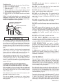
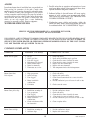
OPERATING, INSTALLATION AND SERVICE MANUAL
STORAGE TYPE GAS WATER HEATER
95001
12/94
WARNING: This information in these instructions must be followed exactly.
Improper installation, adjustment, alteration, service or maintenance can cause
property damage, personal injury or death.
DO NOT STORE OR USE GASOLINE OR OTHER COMBUSTIBLE MATERIALS OR
LIQUIDS NEAR OR ADJACENT TO THIS HEATER OR ANY OTHER APPLIANCE.
WHAT TO DO IF YOU SMELL GAS
1.
2.
3.
4.
Do not try to light any appliance.
Do not touch any electric switch.
Do not use any phone in your building.
Immediately call your gas supplier from a neighborʼs phone following the gas
supplierʼs instructions.
5. If you cannot reach your gas supplier, call the fire department.
THIS APPLIANCE SHALL NOT BE INSTALLED IN ANY LOCATION WHERE
FLAMMABLE LIQUIDS OR VAPORS ARE LIKELY TO BE PRESENT.
FLAMMABLE VAPORS MAY BE DRAWN TO THIS WATER HEATER FROM OTHER
AREAS OF THE STRUCTURE BY AIR CURRENTS.
Installation and service must be performed by a qualified installer, service agency or the
gas supplier.
THIS WATER HEATER SHALL NOT BE INSTALLED IN BATHROOMS, BEDROOMS,
OR ANY OCCUPIED ROOM NORMALLY KEPT CLOSED.
WARNING
This water heater is equipped for one type gas only. Check the data plate near the gas control valve for the correct
gas. DO NOT USE THIS WATER HEATER WITH ANY GAS OTHER THEN THE ONE LISTED ON THE DATA PLATE.
Failure to use the correct gas can cause problems which can result in DEATH, SERIOUS BODILY INJURY OR PROPERTY
DAMAGE. If you have any questions or doubts consult your gas supplier or gas company. Water heaters for bottled,
propane or liquefied petroleum gas (LPG) are different from natural gas models. A natural gas heater will not function safely
on bottled, propane or liquefied petroleum gas (LPG) and no attempt should be made to convert a heater from natural gas
to any other gas.
INSTALLER:
1. AFFIX THESE INSTRUCTIONS TO OR ADJACENT TO WATER HEATER.
2. BEFORE LEAVING PREMISES: REVIEW THIS OPERATION AND SERVICE MANUAL TO BE SURE
HEATER HAS BEEN INSTALLED CORRECTLY. MAKE SURE UNIT IS STARTED AND OPERATED FOR
ONE COMPLETE CYCLE AND WATER TEMPERATURE IS ACCEPTABLE TO THE CONSUMER AT THE
FIXTURES.
OWNER:
1. RETAIN THESE INSTRUCTIONS AND WARRANTY FOR FUTURE REFERENCE.
ALL TECHNICAL AND WARRANTY QUESTIONS SHOULD BE DIRECTED TO THE LOCAL DEALER FROM
WHOM THE WATER HEATER WAS PURCHASED. IF YOU ARE UNSUCCESSFUL PLEASE WRITE TO THE
COMPANY LISTED ON THE WARRANTY OR DATA PLATE WHICH CAME WITH YOUR WATER HEATER.
CALL THIS TOLL FREE NUMBER 1-800-900-9063 WITH ANY QUESTIONS DURING OR AFTER INSTALLATION.
130931 Rev April ʻ07
DANGER
Vapors from flammable
liquids will explode and
catch fire causing death or
severe burns.
Do not use or store flammable
products such as gasoline
solvents or adhesives in the same
room or area near the water
heater.
Keep flammable products:
1. far away from heater,
2. in approved containers,
3. tightly closed and
4. out of children’s reach.
Installation:
Do not install water heater where
flammable products will be
stored or used such as a garage,
basement, storage area or utility
room unless the main burner and
Water heater has a main
burner and pilot flame. The
pilot flame:
1. is on all the time and
2. will ignite flammable vapors
Vapors:
1. cannot be seen,
2. are heavier than air,
3. go a long way on the floor
and
4. can be carried from other
rooms to the pilot flame by
air currents.
pilot flames are at least 18”
above the floor. This will reduce,
but not eliminate, the risk of
vapors being ignited by the main
burner or pilot flame.
Read and follow water heater warnings and instructions.
If owners manual is missing, contact the retailer or manufacturer.
DANGER
Water temperature over 125° F can
cause severe burns instantly or
death from scalds.
Children, disabled and elderly are
at highest risk of being scalded.
See instruction manual before
setting temperature at water
heater.
Feel water before bathing or
showering.
Temperature limiting valves are
available, see manual.
1-89
A 6600874
A
PAGE
130931 Rev April ʻ07
TABLE OF CONTENTS
PAGE
DANGER
A
TABLE OF CONTENTS, INSTALLATION INFORMATION
B
CONSUMER RESPONSIBILITIES, PRESSURE BUILD-UP
1
LOCATION, CLEARANCES FROM COMBUSTIBLE CONSTRUCTION, DISCHARGE OF PURGED GASES
2
AIR SUPPLY, ALL AIR FROM INSIDE THE BUILDING, ALL AIR FROM OUTSIDE THE BUILDING
3
TYPICAL INSTALLATION
4
MECHANICAL EXHAUSTING AND FIREPLACES, VENTING, GAS PIPING INSTALLATION,
INSTALLATION SAFETY WARNING - L.P. UNITS, TEMPERATURE AND PRESSURE RELIEF VALVE
5
COMBINATION SPACE HEATING/POTABLE WATER HEATING, WATER PIPING
6
SOLAR INSTALLATION, CHEMICAL VAPOR CORROSION, INSULATION BLANKET,
INSTALLATION CHECK LIST
7
OPERATION, SAFETY PRECAUTIONS, CONDENSATION, NATURAL GAS MODELS,
L.P. MODELS, OUT OF FUEL, HYDROGEN GAS WARNING, EXPOSURE TO WATER
8
SAFETY INSTRUCTIONS, LIGHTING INSTRUCTIONS
9, 10
TEMPERATURE ADJUSTMENT, BURNER ADJUSTMENT, BURNER MAINTENANCE,
EMERGENCY SHUT DOWN
11
REMOVAL OF BURNER ASSEMBLY, REPLACING BURNER ASSEMBLY,
THERMOCOUPLE AND/OR PILOT REPLACEMENT, DRAINING AND FLUSHING INTERIOR OF TANK,
VENTING SYSTEM INSPECTION, TAMPERING
12
ANODE, WATER HEATER SOUNDS, QUALIFIED SERVICE PERSONS,
COMMON COMPLAINTS TO CHECK BEFORE CALLING FOR SERVICE
13
COMMON COMPLAINTS CONTINUED
14, 15
REPAIR PARTS ILLUSTRATION
WARNING:
16
IMPROPER INSTALLATION, ADJUSTMENT, ALTERATION, SERVICE OR
MAINTENANCE CAN CAUSE INJURY, DEATH OR PROPERTY DAMAGE.
READ AND REFER TO THIS MANUAL.
Please complete the following information at the time of installation. This should be retained and presented along
with the warranty in the event a claim is necessary.
MODEL NUMBER:
SERIAL NUMBER:
INSTALLATION ADDRESS:
TYPE:
THIS WATER HEATER HAS BEEN INSTALLED IN ACCORDANCE WITH THESE INSTALLATION
INSTRUCTIONS AND LOCAL CODE REQUIREMENTS ON
Date
INSTALLER:
B
130931 Rev April ʻ07
PRESSURE BUILD-UP IN
CLOSED WATER SYSTEMS
CONSUMER RESPONSIBILITIES
THIS MANUAL HAS BEEN PREPARED TO ACQUAINT
YOU WITH THE INSTALLATION, OPERATION AND
MAINTENANCE OF YOUR GAS WATER HEATER AND
TO PROVIDE IMPORTANT SAFETY INFORMATION.
The water utility supply meter may contain a check valve,
back flow preventer or water pressure reducing valve. This will
create a closed water system. During the heating cycle of the
water heater, the water expands creating a pressure build-up in
the water system. A temperature and pressure relief valve must
be installed on the water heater (150 PSI maximum pressure
setting. See Temperature and Pressure Relief Valve). To
prevent the temperature and pressure relief valve from
discharging hot water, loss of energy, and reduce the possible
build-up of lime on the temperature and pressure relief valve
seat.
WE URGE YOU TO READ ALL INSTRUCTIONS
THOROUGHLY before attempting installation or operation of
your water heater. Keep these instructions for future reference.
The manufacturer of this water heater will not be liable for any
damages caused by failure to comply with the installation and
operating instructions outlined on the following pages. These
instructions are a guide for the correct installation of your
water heater. If you lack the necessary skills required or have
difficulty following the directions, you should not proceed but
get help from a qualified person for that part of the installation
you do not understand. Your gas-fired water heater is designcertified by the American Gas Association Laboratories. The
installation should conform with the local code or the
authority having jurisdiction, or in the absence of such, the
National Gas Code. ANSI Z223.1 (NFPA 54) 1992. A copy of
the 1992 edition of the Code can be purchased from A.G.A.
Order Processing, 1515 Wilson Boulevard, Arlington, VA
22209 (703) 841-8559. A rating plate identifying your water
heater will be found next to the gas control valve (thermostat).
AN EXPANSION TANK MUST BE INSTALLED on the cold
water supply line. For every 50 U.S. gallons of stored water,
the expansion tank must have a minimum capacity of 1.5
U.S. gallons.
If water heater is installed in a closed water system, contact the
water supplier or local plumbing inspector on how to control
this situation.
When referring to your water heater always have the
information listed on the rating plate readily available.
1
130931 Rev April ʻ07
LOCATION
RESIDENTIAL AREA WHICH MAY NOT BE SUITABLE FOR
HEATER INSTALLATION would include those areas where flam-
Location selection should be as close to the stack or chimney
as practical and as centralized with the piping system as
possible. Water heater should be located in an area not subject
to freezing temperatures.
mable liquids (such as gasoline, solvents, liquefied propane or
butane, etc.) or other substances (such as adhesives, etc.) all of which
emit flammable vapors, may be improperly stored or used. Because of
natural air movement in a room or other enclosed space, flammable
vapors can be carried some distance from where their liquids are being
used or stored. The gas water heater pilot flame or main burner can
ignite such vapors. The resulting flash-back and tire can cause death
or serious burns to anyone in the area, as well as property damage.
For these reasons the water heater must not be installed in an area
where there may be flammable vapors. If such flammables must be
used, all gas burning appliances in the vicinity must be shut off,
including their pilot lights, to avoid vapors igniting and open doors
and windows for ventilation .
The water heater should be located so that the controls and
drain are easily accessible (at least 24 inches in front of the
water heater). The heater should be located in an area where
leakage of the tank or connections will not result in damage to
the area adjacent to the water heater or to lower floors of the
structure. When such locations cannot be provided, a suitable
drain pan must be installed under the heater. Such pans must
limit the water level to a maximum depth of 1 3/4 inches
inside of pan, have a minimum length and width of at least
two inches greater than the diameter of the heater, and must be
piped to an adequate drain. The pan must not restrict
combustion air flow. (Figure 6)
If installation in a garage is your only option, the installation must
be accomplished in a way that the pilot flame and main burner flame
are elevated from the floor at least 18 inches. While this may reduce
BUT NOT eliminate the chances of flammable vapors from a spill
being ignited, gasoline or other flammable substances must never be
stored or used in the same room or area containing a gas water heater
or other open flame or spark-producing appliance.
Under no circumstances is the manufacturer to be held liable
for any water damage in connection with this water
heater.
WARNING
REMEMBER: Flammable vapors may be drawn to this water heater
from other areas of the structure by air currents.
When this heater is installed directly on carpeting, carpeting
must be protected by a metal or wood panel beneath the
appliance extending beyond the full width and depth of the
appliance by at least 3 inches in any direction, or if the
appliance is installed in an alcove or closet, the entire floor
must be covered by the panel. FAILURE TO HEED THIS
WARNING MAY RES ULT IN FIRE HAZARD.
NOTE: HEATER SHALL BE LOCATED OR PROTECTED
SO IT IS NOT SUBJECT TO PHYSICAL DAMAGE BY
MOVING VEHICLES OR AREA FLOODING.
CLEARANCES FROM
COMBUSTIBLE CONSTRUCTION
75-76
100-83
A
18”
18”
B
2”
2”
C
6”
6”
D
6”
6”
Typical Installation in Residential Garages. (Drawing copyright by the
American Gas Association. Used by permission of the copyright holder.)
A minimum of 24 inches front clearance should be provided for
inspection and servicing.
DISCHARGE OF PURGED GASES
When removing purged gases from a piping system, care should
be taken not to create a hazardous condition, such as discharging
the gases into a confined area or in an area which contains an
ignition source.
CERTIFIED FOR
ALCOVE INSTALLATION
2
130931 Rev April ʻ07
AIR SUPPLY
Chimney or Gas Vent
Ventilation Louvers
(each end of attic)
Do not install the water heater in small enclosures unless ample
ventilation and combustion air is supplied. Sufficient fresh air must
be drawn from the outside of the enclosure. Confided areas shall have
two permanent openings. See Figures 2 thru 5 for location of
openings.
Outlet
Air
ALL AIR FROM INSIDE THE BUILDING
The confined space shall be provided with two permanent openings
communicating directly with an additional room(s) of sufficient
volume so that the combined volume of all spaces meets the criteria
for an unconfined space. The total input of all gas utilization
equipment installed in the combined space shall be considered in
making this determination. Each opening shall have a minimum free
area of 1 square inched per 1,000 BTU per hour of the total input
rating of all gas utilization equipment in the confined space, but not
less than 100 square inches. One opening shall be within 12 inches
of the top and one within 12 inches of the bottom of the enclosure.
(Figure 2).
Water
Heater
Furnace
Inlet
Air
Alternate
Air Inlet
Ventilation Louvers For
Unheated Crawl Space
FIGURE 3.
Equipment Located in Confined Spaces; All Air from
Outdoors - Inlet Air from Ventilated Crawl Space and
Outlet Air to Ventilated Attic.
Chimney or Gas Vent
Ventilation Louvers
(each end of attic)
Chimney or Gas Vent
Outlet
Air
Furnace
Opening
Furnace
Water
Heater
Inlet Air Duct
(ends 1 ft. above floor)
Water
Heater
FIGURE 4. Equipment Located in Confined Spaces; All Air from
Outdoors Through Ventilated Attic
FIGURE 2.
Equipment Located in Confined Spaces. All Air from
inside the Building
Chimney or Gas Vent
ALL AIR FROM OUTDOORS
The confined space shall be provided with two permanent openings,
one commencing within 12 inches of the top and one commencing
within 12 inches of the bottom of the enclosure. The openings shall
communicate directly, or by ducts, with the outdoors or spaces (crawl
or attic) that freely communicate with the outdoors.
1. When directly communicating with the outdoors, each opening
shall have a minimum free area of 1 square inch per 4,000 BTU per
hour of total input rating of all equipment in the enclosure.
(Figure 3).
2. When communicating with the outdoors through vertical ducts,
each opening shall have a minimum free area of 1 square inch per
4,000 BTU per hour of total input rating of all equipment in the
enclosure. (Figure 4).
3. When communicating with the outdoors through horizontal
ducts, each duct opening shall have a minimum free area of 1
square inch per 2,000 BTU per hour of total input rating of all
equipment in the enclosure. (Figure 5).
4. When ducts are used, they shall be of the same cross-sectional
area as the free area of the openings to which they connect. The
minimum dimension of rectangular air ducts shall not be less than
3 inches. For other combustion and ventilation air openings,
refer to the National Fuel Gas Code ANSI Z223.1.
Outlet Air Duct
Furnace
Water
Heater
Inlet Air Duct
FIGURE 5.
Equipment Located in Confined Spaces; All Air from
Outdoors
NOTE:
*If the equipment room is located against an outside wall and the air
openings communicate directly with the outdoors, each opening
shall have a free area of not less than one square inch per 4,000 BTU
per hour of the total input rating of all equipment in the enclosure.
Illustrations for Figures 2-5 copy right by the American Gas
Association.
Used by permission of the copyright holder.
3
130931 Rev April ʻ07
4
130931 Rev April ʻ07
POTENTIAL HAZARDOUS
DOWNDRAFT
OPERATION
• EXHAUST FANS
• VENTILATION
SYSTEMS
• CLOTHES DRYERS
• FIREPLACES
• OTHERS
REVERSE
FLOW
the gas valve inlet. Make certain that no pipe dope has become
lodged in the inlet screen of the gas valve. This will restrict the flow
of gas. When attachment of gas piping to gas valve inlet is made,
extreme care must be taken to prevent pipe dope from entering the
gas valve inlet and to avoid excessive torque to prevent cracking of
the gas valve inlet housing. The suggested maximum torque is 31.5
ft. Ibs. The manufacturer of this water heater will not be liable for any
damage or injury caused as a result of a cracked gas inlet from
excessive torque.
After completing all gas connections, check each gas connection and
fitting for leaks. Use a soap and water solution or a commercial leak
detector fluid. NEVER USE MATCHES OR OPEN FLAME WHEN
CHECKING FOR GAS LEAKS.
The water heater and its individual gas shut off valve must be
disconnected from the gas supply piping system during any pressure
testing of that system at test pressures in excess of 1/2 psig (14”
W.C.) or 3.5 kPa.
The water heater must be isolated from the gas supply piping system
by closing its individual manual shut-off valve during any pressure
testing of the gas supply piping system at test pressures equal to or
less than 1/2 psig (14” W.C.) or 3.5 kPa.
EXHAUST
HOOD
NATURAL DRAFT
EQUIPMENT
MECHANICAL EXHAUSTING AND
FIREPLACES
The operation of air-moving devices such as exhaust fans,
ventilation systems, clothes dryers, fireplaces, etc., can affect the
proper operation of gas utilization equipment. Consequently,
special attention must be given to conditions these devices may
create to avoid unsatisfactory operation of the equipment.
VENTING
If the gas valve is subjected to pressure exceeding 1/2 psig, the
damage to the gas valve could result in an extremely hazardous
condition. If this has occurred, the gas valve must be replaced contact
your dealer for service. It is recommended that all service work be
done by qualified service agency.
WARNING
There are various types of vent dampers currently available. Some of these vent dampers are certified by the
American Gas Association Laboratories. The certifications apply to the vent damper device only and does not
mean they are certified for use on this water heater. The use
of these devices is not permitted by the manufacturer of
this water heater.
INSTALLATION SAFETY WARNING
L. P. UNITS: Liquefied petroleum (L.P.) gas is heavier than air and
will remain at floor level if there is a leak. Basements, crawl spaces,
closets and areas below ground level will serve as pockets for
accumulation of leaking gas. Before lighting, sniff at floor level. IF
YOU SMELL GAS, follow applicable instructions on the front cover
or on Page 8. DO NOT OPERATE APPLIANCE UNTIL LEAKAGE IS
CORRECTED.
The water heater must be connected to the chimney. The vent pipe
from the heater to the chimney (vent connector) must be no less than
the diameter of the drafthood outlet on the heater and should slope
upward to the chimney at least 1/4 inch per linear foot. (Figure 6).
Due to great variances in installations, unforeseeable by the
manufacturer of the water heater, increased size vent connectors and
pipes may be necessary for proper venting. Consult your local
utility. They will aid you in determining the proper venting for your
heater from the vent tables in the American National Standards
Z223.1 (NFPA 54) “National Fuel Gas Code.”
Drafthood: If you are replacing an old heater be sure to use the new
drafthood supplied with the new heater. Secure drafthood in place with
screw provided.
WARNING
DO NOT USE OPEN FLAME OR ANY KIND OF SPARK
TO
CHECK FOR LEAKS.
TEMPERATURE AND
PRESSURE RELIEF VALVE
GAS PIPING INSTALLATION
All piping must comply with local and state ordinances or with the
National Fuel Gas code ANSI Z223.1 (NFPA 54), whichever applies.
Use clean black iron pipe or equivalent material approved by local
codes and ordinances for gas piping. Install a ground-joint-union in
the supply line as close to the water heater as possible. A manual gas
shut-off valve should be at least 5 feet above floor level and readily
accessible. A drip leg (consisting of a pipe tee, 4 inch nipple, and a
cap) should be installed as shown in Figure 6.
Make sure the gas supplied to the heater is the same type as listed on
the rating plate. DO NOT ATTEMPT TO USE THIS WATER HEATER
WITH ANY GAS OTHER THAN THE TYPE LISTED ON THE RATING
PLATE.
Compound used for the connection of all gas piping should be
resistant to the action of liquefied petroleum (L.P.) gases. Apply pipe
dope sparingly to the male threads only. DO NOT apply pipe dope to
5
For protection against excessive pressures and/or temperatures, a
temperature and pressure relief valve must be installed in the opening
marked, “temperature and pressure relief valve” a design certified by a
nationally recognized testing laboratory that maintains periodic
inspection of production of listed equipment or materials, as meeting
the requirements for Relief Valves and Automatic Gas Shut-Off
Devices for Hot Water Supply Systems,Z21.22. Pressure rating of the
valve must not exceed the working pressure shown on the data plate
of the water heater.
Relief piping must terminate 6 inches above a floor drain or external
to the building. Do not thread, cap, or plug the end of this discharge
line. Be certain that no contact is made with any live electrical part.
Do not connect discharge line directly to drain. (Figure 6).
To prevent bodily injury, hazard to life or damage to property, the
relief valve must be allowed to discharge water in the event of
excessive temperature or pressure developing in the water heater. The
function of the temperature and pressure relief valve is to discharge
water in large quantities should circumstances demand. If the
discharge pipe is not directed to the drain as shown in Figure 6 or
other suitable means, the water flow may cause property damage.
130931 Rev April ʻ07
DO NOT use this water heater as a replacement for an
existing boiler installation.
The discharge line:
(1) Must not be smaller than the pipe size of the relief valve,
(2) Must not be plugged or blocked,
(3) Must be of material capable of withstanding 210°F
without distortion,
(4) Must be installed so as to allow complete drainage of both
the temperature and pressure relief valve and discharge line,
(5) Must terminate at an adequate drain,
(6) Must not have any valve between the relief valve and the
heater.
Failure to install and maintain a new properly listed
temperature and pressure relief valve will release the
manufacturer from any claims which might result from
excessive temperature or water pressure.
DO NOT use with piping that has been treated with
chromates, boiler seal or other chemicals.
DO NOT add boiler treatment or any chemicals to any heat
piping, since the piping contains potable water.
DO NOT use with ferrous piping. The system should be
installed only with new piping that is suitable for potable
water, such as copper or polybutylene. DO NOT use with
PVC piping.
DO NOT use any pumps, valves, or fittings that are not
com-pletely compatible with potable water piping.
DO NOT use valves that may cause excessive restriction to
water flow. USE FULL FLOW BALL OR GATE VALVES
ONLY.
COMBINATION TEMPERATURE
PRESSURE RELIEF VALVE
MANUAL RELIEF LEVER
DO NOT tamper with the thermostat, gas valve, ignitor
control or temperature and pressure relief valve. Tampering
with any of these components is DANGEROUS and can result
in property damage or severe injury. Tampering voids all
warranties. Only qualified personnel should service these
components.
DISCHARGE LINE TO DRAIN
DO NOT use 50/50 solder in potable water lines.
IF THE S PACE HEATING system requires water
temperature in excess of 120°F, a mixing valve or other means
should be installed in the domestic (potable) hot water supply
to limit the RISK OF SCALD DAMAGE. (See Figure 6)
WARNING
Do not attempt to operate this water heater with cold water inlet
valve closed. Manually operate the temperature and pressure relief
valve at least once a year. To prevent water damage, discharge line
must terminate at an adequate drain. Standing clear of the outlet
(discharge water may be hot), lift and release the lever handle on
the temperature and pressure relief valve to make the valve operate
freely.
S OME JURl S Dl CTl ONS may require a backflow
preventer in the incoming cold water line to the water heater.
In such cases, the temperature and pressure relief valve on the
water heater may weep or relieve due to expansion of the
heated water.
If the heater is installed in a closed system, the temperature and
pressure relief valve may drip at times. If the temperature and
pressure relief valve discharges a full stream of water, have the
system checked. See “Pressure Build-Up in Water System”.
A diaphragm-type expansion tank (such as TACO or
EXTROL) will normally eliminate this weeping condition.
Please read and follow the manufacturer’s instructions for
installation of such tanks.
If the temperature and pressure relief valve on the appliance
discharges periodically, this may be due to thermal expansion in
a closed water supply system (see “Pressure Build-Up in Water
System”). Contact the water supplier of local plumbing inspector
on how to correct this situation. Do not plug the temperature and
pressure relief valve.
WATER PIPING
Pipes and fittings should be installed in compliance with the
installation drawing. Check for dip tube in cold water fitting
before connection of hot and cold water lines. If the indoor
installation area is subject to freezing temperatures, water piping
must be protected. The water heater should be drained if being
shut down during freezing temperatures.
COMBINATION SPACE HEATING /
POTABLE WATER HEATING SYSTEM
If this water heater is to be used to supply both space heating and
domestic potable (drinking) water heating, the instructions listed
below must be followed. Be sure to follow manual(s) shipped
with air handler system.
Have the installer show you where the cold water inlet valve for
the water heater is installed so that you know where and how to
shut the water off. It is recommended that such a valve be located
in close proximity to the cold water inlet of the water heater. See
installation drawing, Figure 6.
Toxic chemicals, such as those used for boiler treatment, shall
NEVER be introduced into this system.
Connect the cold water supply to the fitting marked “C” cold, the
hot water outlet to the fitting marked “H” hot. Do not apply heat
to either of these fittings. If sweat connections are used, sweat
tubing to the adaptor before fitting adaptor to the cold and hot
water fittings. It is imperative that no heat be applied to the water
This unit may NEVER be connected to any existing heating
system or component(s) previously used with a non-potable water
heating appliance.
6
130931 Rev April ʻ07
incidents arising or resulting from the use of external
insulation blankets. The manufacturer will not be liable for
corrosion of parts which may have resulted from the use of
such insulation blankets.
(1) The space between the base and the floor on a gas water
heater is necessary for proper air flow. This space must be
maintained unobstructed. As time passes, the blanket may sag
causing an obstruction of this air passage, resulting in an
unsafe operating condition.
(2) Do not apply insulation to the top of a gas water heater.
This will affect the operation of the draft hood, resulting in an
unsafe operating condition.
(3) Do not cover any access panels leading to burner
compartments, thermostat(s) control, doors, or temperature
&pressure relief valve on the water heater.
(4) Do not cover any labels or instruction material applied to
this water heater. These safety labels and instruction material
must remain on the water heater and be visible for reference by
the user. Do not attempt to remove these labels, as they are a
permanent part of this water heater as required by Certification
Agencies and/or the Federal Government.
heater fittings as they may contain nonmetallic parts. When
making these connections, always use a good grade of pipe
joint compound and be certain that all fittings are drawn up
tight (See Figure 6 for proper installation).
After piping has been installed allow tank to fill with water
and check connections for leaks. To insure complete filling of
the tank, allow air to exit by opening the nearest hot water
faucet until a constant flow of water is obtained.
CAUTION
OPERATING AN EMPTY OR PARTIALLY FILLED WATER
HEATER WILL RESULT IN DAMAGE TO THE TANK.
SOLAR INSTALLATION
When this appliance is used AS A SOLAR STORAGE
HEATER OR AS A BACKUP FOR THE SOLAR SYSTEM,
the following warning applies.
Water supply to this heater
must not exceed 180°F. Water temperature in excess of 180°F
will cause the high limit control to function or open and shut
off gas supply. The high limit control is a single use type that
will require the replacement of the thermostat before the burner
can operate. If the water supply from the solar system is above
120°F, a tempering valve or temperature limiting valves must
be installed in the water supply line to limit the supply
temperature to 120°F .
WARNING
INSTALLATION CHECK LIST*
*This is presented for ease of reference. It is not comprehensive.
All instructions and warnings must be read and adhered to.
A. HEATER LOCATION
Close to area of vent.
Indoors and protected from freezing temperatures.
(Refer to Water Piping Section)
Proper clearance from combustible surfaces observed and
heater not installed directly on carpeted floor.
Sufficient fresh air supply for proper operation of heater.
Air supply free of corrosive elements and flammable
vapors.
Provisions made to protect area from water damage.
Sufficient room to service heater.
CHEMICAL VAPOR CORROSION
The water heater should not be installed near an air supply
containing halogenated hydrocarbons. Water heater corrosion
and component failure can be caused by the heating and
breakdown of airborne chemical vapors. Beauty shops, dry
cleaning establishments, photo processing labs, storage areas
of liquid and powdered bleaches, swimming pool chemicals,
spray can propellants, cleaning solvents, refrigerator and air
conditioning refrigerants, calcium and sodium chloride, waxes
and process chemicals are typical locations and compounds
which are potentially corrosive. These materials are corrosive
at very low concentration levels with little or not odor to
reveal their presence. Products of this sort should not be stored
near the water heater. Air which is brought in contact with the
water heater should not contain any of these chemicals. If
necessary, uncontaminated air should be obtained from remote
or outside sources. NOTE: Contaminated air may cause and
orange colored flame.
B. WATER SUPPLY (See WATER PIPING)
Install a cold water inlet valve (Figure 6).
Heater completely filled with water.
Water connection tight and free of leaks.
C. RELIEF VALVE
Install a new Temperature and Pressure Relief Valve
properly and discharge line run to open drain.
Discharge line protected from freezing (Figure 6).
D. GAS SUPPLY
INSULATION BLANKET
Gas supply same as the type of gas listed on the data plate.
Gas line equipped with shut-off valve, union and drip leg
(Figure 6).
Approved pipe joint compound used.
Soap and water solution used to check all connections and
fittings for possible gas leaks.
CAUTION
Insulation blanket kits which are available for external applications to water heaters are not recommended. However, some
governing bodies require their use in new construction of
additions, regardless of how efficient the water heater may be.
E. VENTING (Figure 6)
Draft diverter properly installed.
Vent connector(s) securely fastened together with screws.
Vent connector(s) at least 6” from combustible material.
Flue baffle engaged in slots if provided in flue tube.
If an insulation blanket is applied to this heater CAUTION
must be exercised not to restrict the proper function of the
heater. The manufacturer of this heater will not be liable for
7
130931 Rev April ʻ07
OPERATION
7. Use an outside phone and immediately call the gas company and the fire department. Ask for instructions. Before
hanging up, give your name and address.
8. DO NOT go back into the building. If help is coming, wait
for it outside of the building.
Safety precautions:
DO turn off heater if it has been subjected to physical damage,
flooding, or fire.
DO NOT turn on heater unless it is filled with water.
DO NOT turn on heater if cold water supply inlet valve is
closed.
DO NOT attempt to light heater until all lighting instructions
are understood and followed. See below and label on heater near
thermostat (Figure 6).
DO NOT allow flammable liquids, such as gasoline or paint
thinner, to be stored or used near heater.
DO NOT allow combustible materials such as newspaper, rags
or mops to accumulate near heater.
L.P.G. (PROPANE, BOTTLED)
GAS MODELS
L. P. G. IS HEAVIER THAN AIR
Should there be a leak in the system, the gas will settle at
FLOOR LEVEL. Basements, crawl spaces, skirted areas
under mobile homes (even when ventilated), closets and
areas below ground level will serve as pockets for the accumulation of gas.
BEFORE LIGHTING SNIFF AT FLOOR LEVEL
IF YOU SMELL GAS, FOLLOW THESE RULES:
1. Open windows.
2. Get all people out of building.
3. DO NOT light matches. Do not smoke.
4. DO NOT touch electrical switches (on or off).
5. Extinguish any open flames.
6. Shut off gas at the L.P. tank outside of the building.
7. Use an outside phone and immediately call the gas company and the fire department. Ask for instructions. Before
hanging up, give your name and address.
8. DO NOT go back into the building. If help is coming, wait
for it outside of the building.
WARNING
TO AVOID POSSIBLE INJURY, FIRE AND EXPLOSION.
READ THESE PRECAUTIONS BEFORE ATTEMPTING
TO LIGHT OR RELIGHT THE PILOT. Check the data plate
near the gas control valve thermostat for the correct gas. DO
NOT USE THIS WATER HEATER WITH ANY GAS
OTHER THAN THE ONE LISTED ON THE DATA PLATE
(Figure 6). Failure to use the correct gas can cause problems
which can result in DEATH, SERIOUS BODILY INJURY,
OR PROPERTY DAMAGE. If you have any questions or
doubts consult your gas supplier or gas company.
CONDENSATION
OUT OF FUEL
Whenever the heater is filled with cold water or hot water is
drawn from a faucet there will be a certain amount of
condensation formed while the burner is “ON”. Moisture from
the products or combustion condenses on the cooler tank
surfaces and forms drops of water which may fall onto the
burner or other hot surfaces to produce a “sizzling” or “frying”
noise. Condensation is normal and should not be confused
with a leaking tank.
When your L.P. tank runs out of fuel, turn off gas at all gas
appliances including gas to pilots. After L.P. tank is refilled,
all appliances must be re-lit according to the manufacturer’s
instructions.
WARNING
The water from condensation will be noted at different times
of the year in varying quantities. This condensation may spill
out of the collector pan onto the floor. Do not confuse this
with a leak. Once the water inside of the heater reaches a
temperature of 120°F, the condensation will stop. Operating
the water heater at the lowest thermostat temperature setting
can keep the water heater in the condensation mode. Adjusting
the thermostat setting slightly higher will overcome this
problem. There is hot water scald potential however if
thermostat is set too high.
HYDROGEN GAS
Hydrogen gas can be produced in a water system that has not
been used for a long period of time (generally two weeks or
more). HYDROGEN GAS IS EXTREMELY
FLAMMABLE. To prevent the possibility of injury under
these conditions, we
recommend the hot water faucet be open for several minutes at
the kitchen sink before you use any electrical appliance which
is connected to the hot water system. Do not light a cigarette,
cigar or pipe. Do not smoke. If hydrogen is present, there will
probably be an unusual sound such as air escaping through the
faucet, as the water begins to flow. Remember no smoking or
open flame near the faucet at the time it is opened.
NATURAL GAS MODELS
IF YOU S MELL GAS :
1. Open windows.
2. Get all people out of building.
3. DO NOT light matches. Do not smoke.
4. DO NOT touch electrical switches (on or off).
5. Extinguish any open flames.
6. Shut off gas at manual shut-off valve.
EXPOSURE TO WATER
Do not use this appliance if any part has been under water.
Immediately call a qualified service technician to inspect the
appliance and to replace any part of the control system and any
gas control which has been under water.
8
130931 Rev April ʻ07
ROBERT SHAW
FOR YOUR SAFETY READ BEFORE LIGHTING
WARNING
If you do not follow these instructions exactly, a fire or explosion may result
causing property damage, personal injury or loss of life.
C. This appliance has a pilot which must be lighted by hand.
When lighting the pilot, follow these instructions exactly.
• If you cannot reach your gas supplier, call the fire
department.
D. BEFORE LIGHTING smell all around the appliance area for
gas. Be sure to smell next to the floor because some gas is
heavier than air and will settle on the floor.
A. Use only your hand to push in or turn the gas control
knob. Never use tools. If the knob will not push in or turn
by hand, don’t try to repair it, call a qualified service
technician. Force or attempted repair may result in a fire or
explosion.
WHAT TO DO IF YOU SMELL GAS
• Do not try to light any appliance.
• Do not touch any electrical switch; do not use any phone in
your building.
• Immediately call your gas supplier from a neighbor’s phone.
Follow the gas supplier’s instructions.
B. Do not use this appliance if any part has been under water.
Immediately call a qualified service technician to inspect
the appliance and to replace any part of the control system
and any gas control which has been under water.
LIGHTING INSTRUCTIONS
7. Turn gas control knob counter-clockwise
“PILOT” position.
1. STOP! It is imperative that you read all the safety warnings
before lighting the pilot.
to
2. Remove outer and inner doors.
3. Turn temperature dial counter-clockwise
settings.
4. Turn gas control knob clockwise
to lowest
8a. For Gas Natural: Light match and hold to pilot. While
holding lighted match to pilot, depress reset button all the
way; hold until pilot lights. Continue to hold the button for
one (1) minute after the pilot was lighted. Release the reset
button and it will pop back up. Pilot should remain lit. If
it goes out, repeat steps 3 through 8.
8b. For Gas LP: Light match and hold to pilot. While
holding lighted match to pilot, depress the gas control knob
all the way; hold until pilot lights. Continue to hold the
knob for one (1) minute after the pilot was lighted. Release
the gas control knob and it will pop back up. Pilot should
remain lit. If it goes out, repeat steps 3 through 8.
• If reset button/gas control knob does not pop up when
released, stop and immediately shut off gas ahead of control
at line valve or tank. Call your service technician or gas
supplier.
• If the pilot will not stay lit after several tries, turn the gas
cock clockwise
to “OFF” position and call your
service technician or gas supplier.
9. Replace the inner door.
10. Turn gas control knob counter-clockwise
to “ON”
position.
to “OFF” position.
5.
To clear any gas that may have accumulated wait ten (10)
minutes. If you then smell gas, STOP! Follow “B” in the
safety warning above on this label. If you don’t smell gas go
to the next step.
6. Find pilot ___ Follow the smaller metal tube from the
thermostat to the pilot.
11. Set temperature dial to desired setting.
12. Replace outer door.
TO TURN OFF GAS TO APPLIANCE
1. Turn temperature dial counter-clockwise
lowest setting.
to
2. Turn cock clockwise
9
to “OFF” position.
130931 Rev April ʻ07
WHITE - ROGERS
FOR YOUR SAFETY READ BEFORE LIGHTING
If you do not follow these instructions exactly, a fire or explosion may result causing property damage, personal
injury or loss of life.
WARNING
A. This appliance has a pilot which must be lighted by
hand. When lighting the pilot, follow these instructions
exactly.
B. BEFORE LIGHTING smell all around the appliance area
for gas. Be sure to smell next to the floor because some
gas is heavier than air and will settle on the floor.
WHAT TO DO IF YOU SMELL GAS
• Do not try to light any appliance.
• Do not touch any electrical switch;
do not use any phone in your building.
• Immediately call your gas supplier from a
neighbor’s phone. Follow the gas supplier’s
instructions.
• If you cannot reach your gas supplier, call the
fire department.
C. Use only your hand to push in or turn the gas control
knob. Never use tools. If the knob will not push in or
move by hand, don’t try to repair it, call a qualified
service technician. Force or attempted repair may result
in a fire or explosion.
D. Do not use this appliance if any part has been under
water. Immediately call a qualified service technician to
inspect the appliance and to replace any part of the
control system and any gas control which has been under
water.
LIGHTING INSTRUCTIONS
OFF
PILOT
ON
ON
OFF
PILOT
OFF
ON
OFF
PILOT
PILOT
GAS CONTROL KNOB
(OFF-PILOT-ON)
130 F MARK
120 F MARK
TEMPERATURE
DIAL
ON
9. Replace the inner door.
10. Turn gas control knob counterclockwise
11. Set temperature dial to desired setting.
12. Replace outer door.
OFF
OFF
PILOT
to
PILOT
8. Depress control knob all the way and hold in.
IMMEDIATELY light the pilot with a match. Continue to
hold the control knob down for about (1) minute after the
pilot is lit. Release knob and it will pop back up. Pilot
should remain lit, if it goes out, repeat steps 3, 4, 7, and 8.
• If knob does not pop up when released , turn clockwise
to “OFF”, stop and immediately call your
service technician or gas supplier.
• If the pilot will not stay lit after several tries, turn the gas
control knob to “OFF”, and call your service technician or
gas supplier.
ON
ON
OFF
7. Turn gas control knob counter-clockwise
“PILOT” position.
ON
1. STOP! It is imperative that you read all the safety warnings
before lighting the pilot.
2. Remove outer and inner doors.
3. Set the thermostat to lowest setting. (Rotate clockwise).
4. Depress gas control knob slightly and turn clockwise
to “OFF”. If knob is in “ON”
turn clockwise to “PILOT’
then depress knob slightly and
turn clockwise
to “OFF”.
to “ON”.
PILOT
NOTE: Knob cannot be turned from “PILOT” to “OFF” unless
knob is depressed slightly. Do not use tools or excessive force.
5.
To clear any gas that may have accumulated wait ten
(10) minutes. If you then smell gas, STOP! Follow “B” in
the safety warning above on this label. If you don’t smell
gas go to the next step.
6. Find pilot ___ Follow the smaller metal tube from the
thermostat to the pilot.
TO TURN OFF GAS TO APPLIANCE
Set the thermostat to lowest setting.
3. Depress gas control knob slightly and turn clockwise
“OFF”. Do not use tools or excessive force.
OFF
to “PILOT”.
PILOT
ON
ON
2. Turn gas control knob clockwise
OFF
1.
PILOT
10
130931 Rev April ʻ07
TEMPERATURE ADJUSTMENT
Some models have values higher or lower than those noted
above. Refer to pressure noted on the label affixed to the front
of the water heater. Consult your local gas company or gas
supplier if correction is necessary.
The temperature selector dial has been adjusted to its
lowest setting when shipped from the factory.
For energy-efficient operation of your water heater, the
recommended temperature setting is approximately 1 30°F.
Households with small children or invalids may require a 120°
F or lower temperature setting to reduce the risk of scald
injury. Some states require a lower temperature setting. Check
with your gas supplier for local requirements governing the
temperature setting. NOTE: The lower the temperature setting
the greater the energy efficiency, both to heat water and to
maintain its temperature during standby periods. Lower water
temperatures also extend the tank life. Remember, no water
heating system will provide exact temperatures at all times.
Allow a few days of operation at this setting to determine the
correct temperature setting consistent with your needs. NOTE:
This water heater, when set at the lower temperature setting,
is not capable of producing hot water of sufficient temperature
for sanitizing purposes.
BURNER ADJUSTMENT
There are no adjustments to this water heater (other than water
temperature selection). The thermostat (gas control valve) is
equipped for total regulation of the main burner and pilot gas
pressures.
WARNING
Only qualified personnel should adjust the pressure regulator.
BURNER MAINTENANCE
At least once every three months visually check burner and
pilot flames and compare with the sketches below.
Observation of the gas flame should show the burner flame to
be a soft blue with the suggestion of slight yellow tips. A
flame of too light of a color may not be a carbonizing flame
and should be avoided. If this is suspected, turn the control to
the off position, allow combustion chamber to cool, and check
the top of the combustion chamber and burner for soot
deposits. If soot exists, clean the burner with soap and water.
If continued sooting occurs, refer to Trouble Symptoms,
Pages 14 and 15.
During winter season or any cold period, you may desire a
higher temperature setting to adjust for the colder incoming
water. However, this adjustment may cause additional
condensation to form on the cooler tank surface. This does not
mean the tank is leaking. Refer to Page 8 for explanation of
this condition. During the summer months, the warmer
incoming water temperatures will benefit the performance of
your water heater and reduce the amount of condensation
developed.
Condensation does not mean that your tank is leaking. Over
40% of reported tank leaks on installation are proven to be
condensation. To avoid unnecessary inconvenience and
expense, make sure the tank is leaking before calling a service
person.
CAUTION: Setting the temperature selector dial higher
provides hotter water, which increases the risk of scald injury.
The water heater thermostat is constructed with a built-in shutoff designed to shut off the gas supply to the main Burner and
pilot Burner in the event the pilot flame is extinguished for
any reason. The thermostat is also equipped with a high
temperature limit switch ECO (Energy Cut Off). The Energy
Cut Off will shut off all gas supplied to the Burner and pilot
Burner in the event the water temperature exceeds 180°F. The
Energy Cut Off switch is a single use switch and is not field
replaceable. Should the Energy Cut Off function (open), the
thermostat must be replaced before the water heater can be
placed in operation again.
VACATION/FREEZING TEMPERATURES __ If the
water heater is to remain idle for 30 days or more, or is subject
to freezing temperatures while shut off, the water heater and
piping should be drained (refer to Page 12), and the drain valve
should be left open. Refer to Hydrogen Gas Warning (Page 8).
GAS PRES S URE __ With the water heater in operation
(main burner on), the maximum supply pressure must not
exceed the specified value below, and the minimum supply
and normal manifold gas pressures are as follows:
S upply Pressure
Manifold
Pressure
Natural Gas:
MAX.
MIN.
10.5” W.C. 5” W.C.
L.P. Gas:
13.0” W.C. 11” W.C.
MA IN BURNE R
P IL OT BU RNE R
EMERGENCY SHUT DOWN
WARNING
NORMAL
4” W.C. - 4.7” W.C.
(see rating plate)
10” W.C.
Should overheating occur or the gas supply fail to shut off,
turn off the manual gas control valve to the appliance and call
a qualified service person to check for the cause.
11
130931 Rev April ʻ07
THERMOCOUPLE AND/OR
PILOT REPLACEMENT
LOOSEN
THREAD
ROTATION
TIGHTEN
THREAD
ROTATION
C A
U
T I
O
N
SEE NOTE BELOW
1. Remove burner assembly. (See “REMOVAL OF BURNER
ASSEMBLY” section.)
2. Grasp the thermocouple line and moderately pull the thermocouple from the pilot burner assembly. NOTE: If for
any reason the thermocouple will not disengage from the
pilot bracket assembly, replace the complete pilot
assembly, follow steps 4 and 5, otherwise go to next step.
3. Push replacement thermocouple through hole in pilot
bracket until it snaps in place. The end of a properly
installed thermocouple should extend approximately 1/4
inch past the tip of the pilot assembly (Go to step 6).
4. Remove No. 8-32 screw holding pilot assembly and pilot
shield (if provided) to main burner (Figure 8, Page 16).
5. Re-install replacement pilot assembly to main burner making sure that pilot shield (if provided) is in the right
location. (Figure 8, Page 16).
6. Replace burner assembly (See “REPLACING THE
BURNER ASSEMBLY” section).
SEE NOTE BELOW
Right Hand
Right Hand
thermocouple
pilot tube
manifold
NOTE: L.P. (propane bottled) gas models have reverse (left
handed) thread on the manifold.
WARNING
DO NOT apply any thread sealant (pipe dope, teflon tape, etc.)
to these connections.
REMOVAL OF THE BURNER ASSEMBLY
For your safety the following procedure should be performed
by qualified service personnel or someone familiar with gas
appliances, as it involves disconnection of gas piping and leak
testing .
1. Turn gas control knob clockwise to “OFF” position. (Page
9 or 10).
2. Open outer and inner doors.
3. Disconnect the thermocouple, pilot tube, and manifold
tube at the thermostat (Figure 7). Note that the propane
(LPG) manifold has left hand thread rotation.
4. Remove the burner spreader by removing the nuts on top
of the spreader.
5. Pull the burner toward the front until the holding bracket
slides out of the slot in the bottom pan. If the burner is
dirty or clogged it cab be cleaned with soap and water.
DRAINING AND FLUSHING
INTERIOR OF TANK
The water heater should be drained if being shut down during
freezing temperatures. Also periodic draining and cleaning of
sediment from the tank may be necessary.
1. “TURN OFF GAS TO APPLIANCE.” (Figure 6)
2. Close the cold water inlet valve to the heater (Figure 6).
3. Open a nearby hot water faucet.
4. Open the heater drain valve. (Figure 6).
WARNING
THIS WATER CAN BE HOT.
5. If the heater is going to be shut down and drained for an
extended period, the drain valve should be left open. Refer
to “Hydrogen Gas” warning, Page 8.
6. To start heater again, read paragraph “Operation” and
REPLACING THE BURNER ASSEMBLY
1. Insert the burner assembly into the opening in the bottom
pan and slide toward the rear so that the burner holding
bracket slides into the slot in the bottom pan. Reinsert the
spreader on to the burner post and replace the two nuts.
2. The manifold tube will now line up to the thermostat
connection.
3. Reconnect the manifold tube and pilot tube. Do not cross
thread these fittings (Figure 7) . Note that the propane
(LPG) manifold has left hand thread rotation.
4. Reconnect the thermocouple.The thermocouple nut should
be started and turned all the way in by hand. An additional
one-quarter turn with a 3/8” open end wrench will be
sufficient to set the lockwasher (Figure 7).
“LIGHTING INSTRUCTIONS”.
VENTING SYSTEM INSPECTION
Check the draft hood relief opening (Figure 6) using a match
flame after 15 minutes of operation. Pass the match flame
around the relief opening of the draft hood. A steady flame
drawn into the opening indicates proper draft. If the flame
flutters or is blown out this would indicate spillage and
corrective action must be made to the vent. (Figure 6).
At least every 3 months a visual inspection should be made of
the venting system. You should look for:
• Obstructions which cause improper venting.
• Damage or deterioration which could cause improper
venting or leakage of combustion products.
CAUTION: OVERTIGHTENING MAY DAMAGE
THE THERMOCOUPLE OR THERMOS TAT.
5. Follow Lighting Instructions to relight water heater.
6. Check for gas leaks with soap and water solution (soap
suds) or liquid detergent. Bubble forming indicates a leak.
FIX ALL LEAKS IMMEDIATELY.
TAMPERING
WARNING
DO NOT US E OPEN FLAME OR ANY KIND OF
S PARK TO CHECK FOR LEAKS .
12
Tampering with the thermostat, gas valve, pilot, burner, or
temperature and pressure relief valve is DANGEROUS and
voids all warranties. Only qualified personnel should service
these components.
130931 Rev April ʻ07
ANODE
1. Possible noises due to expansion and contraction of some
metal parts during periods of heat-up and cool-down do not
represent harmful or dangerous conditions.
In each water heater there is installed at least one anode rod (see
Parts section) for protection of the tank. Certain water
conditions will cause a reaction between this rod and the water.
This is defined as smelly water and removal of the rod will
void any warranties stated or implied. The parts list includes a
special anode that can be ordered if odor and/or discoloration
occur. However, this rod is only good to a certain point, after
which, we can only suggest that a water conditioning
company be contacted to supply filtration equipment.
2. Sediment build-up in the tank bottom will create varying
amounts of noise, and may cause premature tank failure.
Tank bottom may need cleaning. (See “DRAINING AND
FLUSHING INTERIOR OF TANK”).
3. Condensation causes sizzling and popping within the
burner area during heating and cooling periods and should
be considered normal. See “CONDENSATION” Page 8.
WATER HEATER SOUNDS
S ERVICE MUS T BE PERFORMED BY A QUALIFIED INS TALLER,
S ERVICE AGENCY OR GAS S UPPLIER
FOLLOWING IS A LIST OF THE MOST COMMON COMPLAINTS RELATED TO THE USE OF WATER HEATERS. MANY
COMPLAINTS ARE DUE TO ITEMS NOT DIRECTLY RELATED TO THE WATER HEATER. DO NOT ATTEMPT TO
S ERVICE THE WATER HEATER OR PERFORM OTHER RECOMMENDATIONS ON THIS LIS T UNLES S
YOU ARE TRAINED AND QUALIFIED TO DO S O.
COMMON COMPLAINTS
SYMPTOM
POSSIBLE CAUSES(S)
CORRECTIVE ACTION
Burner will not ignite
1.
2.
3.
4.
5.
6.
7.
1.
2.
3.
4.
5.
6.
7.
Burner flame floats
Lifts off ports
1. High gas pressure
2. Orifice too large
3. Flue clogged
No gas
Dirt in gas lines
Pilot line clogged
Main burner line clogged
Defect thermocouple
Defective thermostat
Thermostat set too low
1. Check with utility
2. Replace with correct orifice
3. Clean flue and burner-check for a source of trouble
& correct
4. Provide ventilation by use of louvers in wall or duct
4. Heater installed in
confined area
5. Cold drafts
Burner flame yellow-lazy
Burner flame too high
Check with utility
Notify utility-install dirt trap in gas lines
Clean-check for source of trouble & correct
Clean-check for source of trouble & correct
Replace with new thermocouple
Replace with new thermostat
Turn temperature knob to desired temperature
5. Check source & correct
1.
2.
3.
4.
5.
Insufficient secondary air
Low gas pressure
Flue clogged
Main burner line clogged
Heater installed in
confined area
6. Check main burner orifice
for obstruction
1.
2.
3.
4.
5.
1. Insufficient secondary air
2. Orificetoo large
1. Provide ventilation to heater
2. Replace with correct orifice
Provide ventilation to heater
Check with utility
Clean-check for source of trouble & correct
Clean-check for source of trouble & correct
Provide ventilation by use of louvers in wall or duct
6. Clean or replace orifice
13
130931 Rev April ʻ07
COMMON COMPLAINTS (continued)
SYMPTOM
POSSIBLE CAUSES(S)
CORRECTIVE ACTION
Flame burns at orifice
1. Low gas pressure
2. Defective thermostat
1. Check with utility
2. Replace with new thermostat
Pilot will not remain lit
1.
2.
3.
4.
1.
2.
3.
4.
5.
6.
7.
8.
Low gas pressure
No gas
Dirt in gas lines
Pilot line or
orifice clogged
Thermocouple connection
loose
Defective thermocouple
Cold drafts
Thermostat ECO
switch open
5. Tighten with fingers-then take 1/4 turn with wrench
6. Replace with new thermocouple
7. Check source and correct
8. Replace thermostat
Improper calibration
Thermostat set too high
Sediment or lime in tank
Heater too small for job
Wrong piping connections
Leaking faucets
Gas leaks
Wasted hot water
Long runs of exposed piping
Hot water piping in
outside wall
11. Nofluebaffle
1.
2.
3.
4.
4.
6.
7.
8.
9.
10.
Insufficient hot water
1.
2.
3.
4.
5.
6.
7.
8.
9.
10.
11.
1.
2.
3.
4.
5.
6.
7.
8.
9.
10.
11.
Slow hot water recovery
1. Insufficient secondary air
High operating costs
1.
2.
3.
4.
5.
6.
7.
8.
9.
10.
2.
3.
4.
5.
6.
7.
8.
Drip from relief valve
Check with utility
Check with utility
Notify utility-install dirt trap in gas lines
Clean-check for source of trouble & correct
Low gas pressure
Orifice too small
Improper calibration
Thermostat set too low
Sediment or lime in tank
Heater too small for job
Wrong piping connections
Leaking faucets
Wasted hot water
Long runs of exposed piping
Hot water piping in
outside wall
Replace thermostat
Turn temperature Dial to desired temperature
Drain-check to see if water treatment is necessary
Install adequate heater
Correct piping-dip tube must be in cold inlet
Repair faucets
Check with utility-repair at once
Advise users
Insulate
Insulate
11. Install flue baffle
Check with utility
Replace with correct orifice
Replace thermostat
Turn temperature Dial to desired temperature
Drain-check to see if water treatment is necessary
Install adequate heater
Correct piping-dip tube must be in cold inlet
Repair faucets
Advise users
Insulate
Insulate
1. Provide ventilation to heater. Check flueway & flue
baffle assembly for obstructions.
2. Check with utility
3. Replace with correct orifice
4. Replace thermostat
5. Turn temperature Dial to desired setting
6. Install adequate heater
7. Correct piping-dip tube must be in cold inlet
8. Advise users
Low gas pressure
Orifice too small
Improper calibration
Thermostat set too low
Heater too small for job
Wrong piping connections
Wasted hot water
1. Excessive water pressure
2. Heater stacking
3. Closed water system
1. Use pressure reducing valve and pressure relief valve
2. Lower thermostat setting
3. See Page 1, “Pressure Build-up in Water System”
14
130931 Rev April ʻ07
COMMON COMPLAINTS (continued)
SYMPTOM
POSSIBLE CAUSES(S)
CORRECTIVE ACTION
Thermostat fails to
shut off
1. Defective thermostat
2. Improper calibration
1. Replace with new thermostat (control value)
2. Replace control valve
Condensation
1. TemDerature settina too low
1. See page 8 and 11
Combustion odors
1. Insufficient secondary air
2. Flue clogged
1. Provide ventilation to heater
2. Clean-check for source of trouble & correct. Check
flueway & flue baffle & burner
3. Provide ventilation by use of louvers in walls
or ducts
Smoking and carbon
3. Heater installed in
confined area
formation (sooting)
1. Insufficient secondary air
2. Low gas pressure
1. Provide ventilation to heater. Check flueway,
& flue baffle assembly & burner
2. Check with utility
3. Replace with correct orifice
4. Clean-check for source of trouble & correct
5. Replace with new thermostat (control valve)
6. Provide ventilation by use of louvers in wall or duct
3.
4.
5.
6.
Orifice too large
Flue clogged
Defective thermostat
Heater installed in
confined area
7. Burner flame yellow-lazy
7. See section “Burner Flame Yellow-Lazy” Page 13
1. Low gas pressure
2. Pilot line or
orifice clogged
3. Wrong pilot burner
1. Check with utility
2. Clean-check for source of trouble & correct
Pilot flame too large
1. Wrong pilot burner
1. Replace
Smelly water
1. Sulfides in the water
1. Repiace the anode with a special anode
Pilot flame too small
3. Replace
15
130931 Rev April ʻ07
REPAIR PARTS ILLUSTRATION
PARTS REPLACEMENT MUST BE PERFORMED BY A QUALIFIED INSTALLER, SERVICE AGENCY OR GAS
ITEM
NO.
PARTS DESCRIPTION
1 DRAFTHOOD
2 REDUCER RING (SOME MODELS)
3
4
5
6
7
8
9
1
BAFFLE
COLD WATER DIP TUBE
HEAT TRAP (SOME MODELS)
ANODE ROD (NOT SHOWN)
TEMPERATURE & PRESSURE RELIEF VALVE
Drain VALVE
PROPANE GAS THERMOSTAT WILL BE
THERMOSTAT
MARKED FOR LP GAS ONLY
2
5
3
4
7
10 MAN I FOLD
11 ORIFICE
12 MAIN BURNER
13
14
15
16
17
BURNER SPREADER
THERMOCOUPLE
PILOT TUBE
PILOTASSEMBLY
CLEANOUT PLATE (SOME MODELS)
9
18
18 CLEANOUT O RING (SOME MODELS)
19 JACKET CLEANOUT COVER (SOME MODELS)
20 INNER DOOR (SOME MODELS)
8
17
19
21 OUTER DOOR
20
13
21
LEGEND
Special anode rod (see page 13)
14
12
16
Temperature & Pressure Relief Valve is required, but may
not be factory installed.
15
11
It is imperative the replacement main burner, main burner
orifice, manifold, pilot burner, and the thermostat be
ordered for the proper gas type. Natural gas thermostat will
be marked with a 3.5 pressure setting. Propane gas
thermostat will be marked “For L.P. Gas Only.”
10
FIGURE 8
WHEN ORDERING REPAIR PARTS ALWAYS GIVE THE FOLLOWING INFORMATION: (1 ) MODEL AND SERIAL NUMBER,
(2) TYPE OF GAS, (3) ITEM NUMBER, (4) PARTS DESCRIPTION.
THE ABOVE PARTS MAY BE ORDERED THROUGH YOUR PLUMBER, A LOCAL SUPPLY COMPANY, OR DIRECT FROM
THE FACTORY. PARTS WILL BE SHIPPED AND BILLED AT PREVAILING PRICES AT THE TIME OF SHIPMENT. REFER TO
YOUR WARRANTY FOR FACTORY ADDRESS.
16
130931 Rev April ʻ07