1
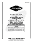
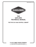
EFFECTIVE DATE 2-99 THE GAYLORD VENTILATOR TECHNICAL MANUAL FOR GRAND “GX” SERIES NON WATER-WASH VENTILATORS WITH MODEL C-250 START/STOP SWITCH GAYLORD INDUSTRIES, INC. An Illinois Tool Works Company 10900 S.W. AVERY STREET • P.O. BOX 1149 • TUALATIN, OREGON 97062-1149 U.S.A. 1-800-547-9696 • 503-691-2010 • FAX: 503-692-6048 • email: [email protected] GAYLORD INDUSTRIES, INC. “Undisputed World Leader in Engineered Systems for Commercial Kitchens”tm World Headquarters: P.O. Box 1149 • Tualatin, Oregon 97062-1149 U.S.A. To Our Customers. . . Congratulations on your recent purchase of a Gaylord kitchen exhaust hood system. We are proud to be able to provide you with a quality product that incorporates the latest engineering concepts and is a result of over 50 years of experience in the foodservice kitchen exhaust industry. If you have other Gaylord equipment such as a Gaylord Utility Distribution System, Quencher Fire Protection System, or Roof Top Air Handling Equipment, etc., please refer to the corresponding supplementary equipment manuals. If you have further questions, please call us toll free at 1-800-547-9696. We are more than happy to help. Sincerely, Gaylord Industries, Inc. STREET ADDRESS: 10900 S.W. Avery Street, Tualatin, Oregon 97062-8549 U.S.A. PHONE: 503-691-2010 • 800-547-9696 • FAX: 503-692-6048 • email: [email protected] • www.gaylordusa.com COMMERCIAL KITCHEN EXHAUST SYSTEMS • FIRE PROTECTION • UTILITY DISTRIBUTION • ROOF TOP UNITS • POLLUTION CONTROL TABLE OF CONTENTS OPERATION .......................................................................................................... 1 STANDARD MODELS ........................................................................................... 2 MAINTENANCE AND CLEANING INSTRUCTIONS ............................................ 3 TROUBLESHOOTING ........................................................................................... 3 MEASURING INLET SLOT VELOCITY ................................................................. 5 WIRING DIAGRAMS .............................................................................................. 7 PARTS LIST ........................................................................................................... 8 WARRANTY PATENT NUMBERS U.S.A.: 4,266,529 4,281,635 4,356,870 CANADA: 1,139,151 1,155,366 GERMANY: 8,034,240 ALL RIGHTS RESERVED. NO PART OF THIS BOOK MAY BE REPRODUCED, STORED IN A RETRIEVAL SYSTEM, OR TRANSMITTED IN ANY FORM BY AN ELECTRIC, MECHANICAL, PHOTOCOPYING, RECORDING MEANS OR OTHERWISE WITHOUT PRIOR WRITTEN PERMISSION OF GAYLORD INTERNATIONAL, INC. COPYRIGHT 1999. © Copyright 1999, Gaylord Industries, Inc. The manufacturer reserves the right to modify the materials and specifications resulting from a continuing program of product improvement or the availability of new materials. ADDITIONAL COPIES $10.00 OPERATION The Gaylord “GX” Series Non Water-Wash Ventilator offers simplicity, economy and performance that no other ventilator can offer. The unique “extractor insert” gives a grease extraction efficiency far superior to that of a typical mesh or extractor filter. The Gaylord “GX” Series Ventilators are UL Listed and meet all the requirements of NFPA #96. DUCT TAKE-OFF COLLAR 280° F FUSE LINK LIGHT FIXTURE TRANSITION AREA BAFFLES FAN OPERATION To operate the exhaust fan, push the “start” or “stop” button on the Gaylord exhaust fan switch. GREASE EXTRACTION INLET SLOT The Gaylord “GX” Series Ventilator extracts 90% of the grease, dust, and lint particles from the airstream passing through it. Grease extraction is accomplished by a unique, removable stainless steel “extractor insert” which incorporates a series of horizontal baffles. As the air moves through the ventilator at high speed, it is forced to make a series of turns around these baffles, forcing the heavier-than-air particles of grease, dust, and lint to be thrown out of the airstream by centrifugal force. The liquefied grease then drains off into a grease cup. The extractor inserts are available in two sizes: 151/2" (5 3/4 lbs.) and 191/2" (6 3/4 lbs.). IMPORTANT NOTE: Never operated ventilator without extractor inserts in place. EXTRACTOR INSERT SURFACE FIRE PROTECTION NOZZLE GREASE EXTRACTION CLEANING At the end of the cooking day, or at periodic intervals, the inserts are removed and can be washed either in a dishwasher or soaked and rinsed off. To ease in the removal of the extractor inserts, an “Extractor Removcal Tool” is available which eliminates the need for kitchen personnel to climb up on the cooking equipment. EXTRACTOR INSERT GREASE GUTTER GREASE CUP FIRE PROTECTION EXTRACTOR REMOVAL TOOL NFPA #96 requires the use of surface, duct and plenum protection on all non water-wash hoods. It is these systems that are the first line of defense against equipment fires. If the surface system fails to extinguish the fire, the ventilator's internal fire protection system then acts as a back-up. This is accomplished by a spring loaded fire damper which is activated by a 280° F fusible link or thermostat located at the duct collar. In the event of a fire, should the detection device reach 280° F, the damper would close preventing the flames from entering the duckwork and spreading to other parts of the building. The fire is contained in the kitchen area where it can be properly fought. CLEANING EXHAUST DUCT COLLAR FIRE PROTECTION NOZZLE FIRE DAMPER IN CLOSED POSITION MELTED 280° F FUSE LINK PLENUM FIRE PROTECTION NOZZLE Surface, duct collar and plenum fire protection utilizing The Gaylord Quencher System or other fire protection systems currently on the market can be factory installed as an option. SURFACE FIRE PROTECTION NOZZLE EXHAUST FAN START/STOP SWITCH Model C-250 FIRE PROTECTION FIGURE 1 1 STANDARD MODELS MODEL “GX-AB” MODEL “GX-CE” MODEL “GX-BDL” APPLICATION - Backshelf style for all types of counter height equipment. APPLICATION - Pass-over style for all types of counter height equipment. APPLICATION - Wall mounted canopy style for all types of equipment. MODEL “GX-BDL-O” MODEL “GX-BDL-DS-CL” MODEL “GX-BDL-DS” APPLICATION - Eyebrow canopy style for direct mounting to all types of ovens such as roast, bake, and reel types. APPLICATION - Used for cafeteria lines or any other single line island arrangement. APPLICATION - Used for typical island style cooking arrangement. FIGURE 2 STANDARD MAKE-UP AIR OPTIONS The make-up air options shown below are available on all BDL Series Ventilators. FIRE DAMPER MODEL “MAW” SERIES FRONT FACE DISCHARGE This method of introducing make-up air into the kitchen is flexible and has many advantages. Make-up air is discharged through stainless steel perforated panels as illustrated (MAW Series) or optional registers. Typical supply volume is 80% of the exhaust or more, depending on air balance desired. Supply air temperatures should range from 60 to 65°F (16 to 18°C), but may be as low as 50°F (10°C) depending on air volume, distribution, and internal heat load. MODEL “MAP” SERIES DOWN DISCHARGE This method of introducing air into the kitchen area is typically used when “spot cooling” of the kitchen staff is desired to help relieve the effects of severe radiant heat generated from equipment such as charbroilers. Discharge velocities must be carefully engineered to avoid air turbulence at the cooking surface, discomfort to personnel and the cooling of foods. The amount of supply air introduced may be up to 80% of exhaust depending upon the type of cooking equipment involved, and the air temperature should be 65° F (18°C) or higher. 2 MODEL “MAI” SERIES INTERNAL DISCHARGE This method of introducing air into the hood is typically referred to as the “short circuit” method. This design has very limited applications and the amount of supply air able to be introduced varies considerably with the type of cooking equipment. This air may be untempered air in most areas depending upon climatic conditions and the type of cooking equipment. The difference between the quantity of air being introduced and the amount of air being exhausted must be supplied through a traditional make-up air system. MAINTENANCE AND CLEANING INSTRUCTIONS CLEANING INSPECTION AND CLEANING REQUIREMENTS At the end of each cooking day, the exposed interior surfaces of the ventilator should be wiped down and the grease cup emptied. During the course of operation, grease particles are gradually collecting inside the extractor inserts. Daily, or at periodic intervals, depending on the type of cooking, the extractor inserts must be removed and cleaned. To clean, proceed as follows: 1. Remove extractor inserts by hand or by using the extractor removal tool. CAUTION: Care should be taken when removing extractors, especially over fryers. It is recommended that the cooking equipment be cooled down and the fryers be covered prior to removing extractors. To remove, lift up slightly on extractor insert and pull straight out. 2. Extractor inserts may be cleaned either by using a dishwasher or by washing in a sink using hot water and a degreasing detergent. Formula G-510 is highly recommended for this application. For information contact: The 1998 edition of NFPA-96 (Standard for Ventilation Control and Fire Protection of Commercial Cooking Operations) require that hoods, ducts and exhaust fans be inspected by a properly trained, qualified and certified company or person(s) in accordance with the following table. 20/10 Products Inc. Upon inspection, if found to be contaminated with deposits from greaseladen vapors, the entire exhaust system shall be cleaned by a properly trained, qualified, and certified company or person(s) acceptable to the authority having jurisdiction in accordance. When a vent cleaning service is used, a certificate showing date of inspection or cleaning shall be maintained on the premises. After cleaning is completed, the vent cleaning contractor shall place or display within the kitchen area a label indicating the date cleaned and the name of the servicing company. It shall also indicate areas not cleaned. EXHAUST SYSTEM INSPECTION SCHEDULE Phone: 800-286-2010 Fax: 503-363-4296 email:[email protected] P.O. Box 7609 Salem, Oregon 97303 3. With extractor inserts removed, wipe and clean the back wall and the grease gutter with hot detergent water. NOTE: If a steam or hot water pressure washer is used for periodic cleaning of the interior, connect a hose to the gutter drain and lead it to a floor sink or large bucket to drain off water. 4. To replace the extractor inserts, care must be taken to insure that point A rests in the rear clip as illustrated at right. Systems serving solid fuel cooking operations Monthly Systems serving high-volume cooking operations such as 24-hour cooking, charbroiling or wok cooking Quarterly Systems serving moderate-volume cooking operations Semiannually Systems serving low-volume cooking operations, such as churches, day camps, seasonal businesses, or senior centers Annually 5. If the ventilator(s) has a fuse link operated supply duct fire damper NFPA-96 requires inspection of the fuse link every 6 months and replacement annually. NOTE: NEVER OPERATE THE VENTILATOR IF THE EXTRACTOR INSERTS ARE NOT IN PLACE. FIGURE 4 CAUTION: Care should be taken when removing extractors, especially over fryers. It is recommended that the cooking equipment be cooled down and the fryers be covered prior to removing extractors. FIGURE 3 TROUBLESHOOTING POOR SMOKE CAPTURE Poor smoke capture may also be caused by inadequately and/or improperly introduced make-up air. Make-up air must be supplied for replacement of air exhaust through all kitchen exhaust systems. Makeup air should be delivered through registers at ceiling height, and distributed throughout the kitchen area. A general “rule of thumb” is that 75% to 80% of the replacement air should be fresh, conditioned (heated or cooled) air brought into the kitchen area, with the remaining 20% to 25% allowed to flow into the kitchen from adjacent areas. Smoke loss may also be caused by too much make-up air or make-up air being blown directly at the ventilator. Make-up air should not exceed 90% of exhaust air and should be introduced into the kitchen evenly and away from the ventilator. If the ventilator is not exhausting properly and smoke is escaping, first check the extractor inserts to make sure they are in place properly. If they are, the probable cause of smoke loss is a malfunctioning fan. The fan can be checked by taking air readings at the inlet slot. Refer to page 5 for proper method of taking air readings. If the air velocity is low, check the following: 1. 2. 3. 4. Broken or slipping fan belt. Duct access panels left open. Closed fire damper. Proper exhaust fan size (exhaust fan must be capable of delivering specified CFM and static pressure). 5. Proper rotation of fan wheel. 3 TROUBLE SHOOTING EXHAUST FAN WILL NOT COME ON ELECTRICALLY OPERATED FIRE DAMPER If the exhaust fan does not come on when the fan switch is flipped or start button is pushed, check the following: An electrically operated damper is optional equipment. Ventilators equipped with this option are easily recognizable in that they have a reset handle with a red knob. 1. Magnetic starter for exhaust fan - It is possible that the overload protectors within the magnetic starter switch may have actuated and stopped the fan. Push the “reset” button on the magnetic starter, and then restart the exhaust fan. 2. In the event that an H.O.A. (Hands Off/Automatic) type magnetic starter switch is used, check the selector switch to make sure it is in the automatic position. 3. Check exhaust fan motor circuit breaker and check fuses in disconnect switch normally located next to the fan. 4. Check 120 volt control power and 3 phase blower power at circuit breaker panel. GREASE EXTRACTION The Gaylord “GX” Series Ventilator extracts up to 90% of the grease, dust, and lint particles from the airstream passing through it, when operated and maintained in accordance with design specifications. If it appears that the ventilator is not extracting properly, check the inlet slot velocity as described on Page 5. DAMPER CONTROL SWITCH MODEL C-61 / GXSH FIG. 6 FUSE LINK OPERATED DAMPER A spring loaded fire damper is standard equipment for all “GX” Series Ventilators. The damper is located at the duct collar and is activated by a 280°F (137°C) fuse link. The damper control switch, which contains the spring, is mounted at the side of the duct collar. In the event of a fire, and if the fuse link reaches 280°F (137°C) , the link will separate, the damper will close, and the exhaust fan will shut off. To resume normal operation, the fuse link must be replaced. Most codes require fuse links to be inspected semiannually and replaced annually. It is recommended that a professional service organization be contracted to perform this service. Normally this could be the same company that services the fire protection system. IMPORTANT NOTE: All replacement fuse links must be UL Listed and rated for 280°F (137°C). The electric damper is controlled by a 280°F (137°C) thermostat mounted at the duct collar. In the event of a fire and if the thermostat reaches 280 °F (137°C), the fire damper will automatically close and the exhaust fan will shut off. To resume normal operation, the red knob must be reset until the damper latches open. FUSE LINK ACTIVATED FIRE DAMPER DUCT COLLAR ACCESS TO DAMPER AND FUSE LINK DAMPER CONTROL SWITCH MODEL C-61/GXB ACCESS TO DAMPER CONTROL SWITCH AND DUCT COLLAR ACCESS FIG. 7 DAMPER CONTROL SWITCH MODEL C-61/GXB FIG. 5 THERMOSTATICALLY ACTIVATED FIRE DAMPER DUCT COLLAR ACCESS TO DAMPER AND THERMOSTAT DAMPER CONTROL SWITCH COVER C-61/GXSH ACCESS TO DAMPER CONTROL SWITCH AND DUCT COLLAR ACCESS RESET HANDLE FIG. 8 4 MEASURING INLET SLOT VELOCITY MEASURING INLET SLOT VELOCITY Smoke capture and grease extraction efficiency are dependent upon the proper air velocity at the inlet slot of the ventilator. INLET SLOT PLANE SENSING HEAD The required average slot velocities are shown on the “Air Velocity Chart” below. If the slot velocity is below the required average, the exhaust fan must be adjusted accordingly. HEIGHT OF INLET SLOT NOTE: The height of the inlet slot can vary depending upon the design of the ventilator. It is, therefore, important to first measure the inlet slot and compare it to the chart below to determine the required average inlet slot velocity. The designed CFM per lineal foot is related to the velocity as shown on the chart below. The total CFM for the ventilator can be found on the ventilator nameplate. (See Figure 12). POSITION SENSING HEAD ON INLET SLOT PLANE AIR VELOCITY CHARTS LOWER LIP OF INLET PLANE FOR ALL “GX” SERIES EXCEPT “GX-DS” Nominal Height of Inlet Slot 3" 4" Without Custom Air Baffles With Custom Air Baffles Designed CFM per Lineal Ft. Required Average Inlet Slot Velocity (FPM) Designed CFM per Lineal Ft. Required Average Inlet Slot Velocity (FPM) 250 1000 150 600 270 1080 160 N/A 285 1140 170 N/A 300 1200 180 720 400 1200 240 725 450 1350 270 820 470 1425 280 848 500 1500 300 900 FIGURE 9A INLET SLOT PLANE SENSING HEAD HEIGHT OF INLET SLOT POSITION SENSING HEAD ON INLET SLOT PLANE CUSTOM AIR BAFFLE LOWER LIP OF INLET PLANE FOR “GX-DS” SERIES VENTILATORS Designed CFM per Lineal Ft. Required Average Inlet Slot Velocity Total Both Slots Front Slot Rear Slot Front Slot Rear Slot 300 150 150 600 680 400 250 150 1000 680 500 310 190 1200 860 FIGURE 9B LOWER LIP OF REAR INLET SLOT Air velocity readings less than what is specified on the “Air Velocity Chart” may allow smoke and grease to escape the confines of the ventilator and/or reduce grease extraction efficiency. This can result in grease deposits which lead to sanitation problems or fire hazards if left uncorrected. If air velocity readings are higher than those specified, it will require more energy to operate the exhaust fan and excessive noise levels will result. PLACE BOTTOM OF SENSING HEAD EVEN WITH LOWER LIP OF INLET SLOT AND TOP OF PROBE HEAD AGAINST BACK WALL OF VENTILATOR AS SHOWN Higher or lower velocities than the required average will normally put the entire heating and ventilating system out of balance. FIGURE 9C When measuring the air velocity it is very important to take an average reading across the inlet slot plane as illustrated in Figures 9A, B, or C, or Figure 10. Positioning the sensing head incorrectly will give velocity readings that cannot be compared to the “Air Velocity Chart”. The sensing heads shown in Figure 9 are of the design typically used on anemometer type instruments. REAR SLOT OF MODEL “BDL-DS” SERIES AND “BDL-DS-CL” SERIES FIGURE 9A, B, & C CROSS SECTION OF TYPICAL VENTILATOR INLET SLOT 5 MEASURING INLET SLOT VELOCITY INLET SLOT PLANE PROBE HEAD NOTE: IF A VELOMETER TYPE INSTRUMENT WITH PROBE HEAD IS USED, AS ILLUSTRATED AT LEFT, A MINIMUM OF THREE (3) READINGS MUST BE TAKEN ACCROSS THE INLET SLOT PLANE, AS SHOWN, AND THEN AVERAGED. AIRFLOW THIRD READING SECOND READING FIRST READING NOTE: THE VELOMETER PROBE HEAD SHOWN IS FROM A DWYER MODEL 460. WHEN THIS MODEL IS USED IT IS IMPORTANT THAT THE METER BASE BE HELD VERTICAL. LOWER LIP OF INLET PLANE FIGURE 10 LENGTH OF INLET SLOT SENSING HEAD APPROXIMATELY EQUAL APPROXIMATELY EQUAL APPROX. 6" IN FROM ENDS FOR VENTILATORS UP TO 6'-0" LONG, TAKE A MINIMUM OF TWO (2) READINGS. FOR VENTILATORS LONGER THAN 6'-0", TAKE A MINIMUM OF THREE (3) VELOCITY READINGS AS ILLUSTRATED. IF DAMPER CONTROL SWITCH IS LOCATED IN THE CENTER, TAKE CENTER READING 6" TO EITHER SIDE OF THE CONTROL FIGURE 11 ENGINEERING DATA UL ® LISTED 370Y EXHAUST HOOD WITH EXHAUST DAMPER THIS EXHAUST HOOD HAS BEEN TESTED TO STANDARD UL 710 "EXHAUST HOODS FOR COMMERCIAL COOKING EQUIPMENT" THIS EXHAUST HOOD IS LISTED UNDER UL FILE NUMBER MH11403 THIS EXHAUST HOOD MEETS ALL REQUIREMENTS OF THE LATEST EDITION OF NFPA-96 PATENT NUMBERS: USA, 3,247,776; 3,611,909; 3,788,041; 4,072,143; 4,266,529; 4,281,635; 4,356,870; Australia, 481,510; 465,037; Canada, 744,166; 759,710; 926,689; 1,139,151; 968, 559; 940,761; 1,004,155; 1,086,126; France, 7,227,217; 7,332,718; 2,351,362; Germany, 2,346,196; 1,604, 173; 3, 152, 501Great Britain, 1,350,857; 1,396,065; 1,558,537; Japan, 650,269; 797,637; 917, 077; 1,045,507; 726,884; 1, 580, 556; New Zealand, 162,024; 167,964; Switzerland, 560,358; other U.S. and foreign patents pending. TOTAL CFM HERE 1. MINIMUM TOTAL EXHAUST VOLUME FOR THIS HOOD SECTION C.F.M. 2. MAXIMUM TOTAL SUPPLY VOLUME FOR THIS HOOD SECTION C.F.M. 3. EXHAUST STATIC PRESSURE AT DUCT COLLAR W.G. 4. SUPPLY STATIC PRESSURE AT DUCT COLLAR W.G. 5. THIS HOOD SECTION SUITABLE FOR APPLIANCES WITH MAXIMUM COOKING SURFACE TEMPERATURE OF: °F FOR LINEAL FT. OF HOOD °F FOR LINEAL FT. OF HOOD 7. ELECTRICAL RATING OF LIGHT FIXTURES: 120 VOLT, 60 HZ. OR 220 VOLT, 50 HZ. OVERALL RATING - 12 AMPS OR LESS 8. ON "GX" SERIES VENTILATORS EQUIPPED WITH FUSE LINK OPERATED EXHAUST FIRE DAMPER USE ONLY 280° F (137° C), RATED 30 LBS. (13.6 kg.) MIN. UL LISTED FUSIBLE LINK FOR REPLACEMENT 9. ON "FX" AND "GX" SERIES VENTILATORS EQUIPPED WITH FUSE LINK OPERATED EXHAUST FIRE DAMPER USE ONLY 212° F (100° C), RATED 30 LBS. (13.6 kg.) MIN. UL LISTED FUSIBLE LINK FOR REPLACEMENT 10.IF HOOD IS EQUIPPED WITH INTEGRAL MAKE-UP AIR WITH FUSE LINK OPERATED FIRE DAMPER USE ONLY 165° F (74° C), RATED 30 LBS. (13.6 kg.) MIN. UL LISTED FUSIBLE LINKS FOR REPLACEMENT 11.DUCTWORK AND EXHAUST FAN A. STATIC PRESSURE OF DUCT MUST BE ADDED TO VENTILATOR STATIC FOR TOTAL SYSTEM STATIC B. ALL DUCTWORK MUST BE WELDED WATERTIGHT HOOD MOUNTING REQUIREMENTS MINIMUM DISTANCE FROM COOKING SURFACE TO FRONT LOWER EDGE OF HOOD MAXIMUM DISTANCE FROM COOKING SURFACE TO FRONT LOWER EDGE OF HOOD MINIMUM OVERHANG FROM FRONT OF HOOD CAVITY TO FRONT OF COOKING SURFACE MAXIMUM SETBACK FROM FRONT OF HOOD CAVITY TO FRONT OF COOKING SURFACE MINIMUM OVERHANG FROM SIDE OF HOOD TO EDGE OF COOKING SURFACE SERIAL NO: GIMODEL NO: WORLD HEADQUARTERS GAYLORD INDUSTRIES, INC. A SUBSIDIARY OF GAYLORD INTERNATIONAL, INC. 10900 S.W. AVERY STREET TUALATIN, OR 97062-8549 USA UL-GX/FX/SG-FD 996 FIGURE 12 6. REFER TO GAYLORD VENTILATOR TECHNICAL MANUAL FOR INLET VELOCITY REQUIREMENTS AND METHOD OF CHECKING VELOCITY MAINTENANCE INSTRUCTIONS 1. REMOVE, INSPECT AND CLEAN FILTERS ON "SG-FD" OR "CFX" SERIES OR GAYLORD EXTRACTOR INSERTS ON "GX" SERIES AS REQUIRED 2. REMOVE AND EMPTY GREASE CUP AS REQUIRED 3. CAUTION - DO NOT OPERATE VENTILATOR WITHOUT FILTERS OR EXTRACTORS IN PLACE 4. REPLACE FILTERS IN "SG" AND "FX" SERIES ONLY WITH UL CLASSIFIED GREASE FILTERS OR GAYLORD EXTRACTOR INSERTS IN "GX" SERIES 5. IF THE VENTILATOR(S) HAS A FUSE LINK OPERATED EXHAUST OR SUPPLY DUCT FIRE DAMPER THE NATIONAL FIRE PROTECTION ASSOCIATION'S PAMPHLET NFPA-96 REQUIRES INSPECTION OF THE FUSE LINK EVERY 6 MONTHS AND REPLACED ANNUALLY. REFER TO THE GAYLORD VENTILATOR TECHNICAL MANUAL FOR DETAILS. 6 The total required exhaust volume can be found stamped on the UL nameplate located on each hood section. WIRING DIAGRAMS C-250 FAN ON/OFF SW. FURNISHED BY GAYLORD MFG., INSTALLED BY ELECTRICAL CONTRACTOR DAMPER FIRE SWITCH LOCATED AT EACH EXHAUST DUCT COLLAR L1 L2 L3 EXHAUST FAN ELECTRICAL SERVICE FOR EXHAUST FAN 120, 220, OR 440 V. MAG. STARTER SWITCH WITH 120 VOLT HOLDING COIL (BY OTHERS) T1 T2 T3 FIELD J-BOX ALL EXTERNAL CONTROL WIRING SHALL BE 12 GA. MIN. OR AS PER APPLICABLE CODES. EXHAUST FAN MOTOR BY OTHERS L1H L2 N 120 OR 220 VOLT SERVICE FIELD WIRING BY OTHERS WIRING BY GAYLORD MFG. STANDARD WIRING DIAGRAM FOR “GX” SERIES VENTILATORS WITH FUSE LINK ACTIVATED FIRE DAMPER DAMPER CONTROL SWITCH MODEL C-61 GXS SERIES DAMPER CONTROL SWITCH MODEL C-61 GXS SERIES DAMPER COIL TO MATCH SUPPLY BLOWER SW. VOLTAGE 1 8 THERMOSTAT J-BOX LOCATED AT DUCT COLLAR 5 3 THERMOSTAT WIRED IN PARALLEL 1 8 WIRED IN SERIES WIRED IN SERIES 5 3 WIRED IN PARALLEL WIRED IN PARALLEL THERMOSTAT WIRED IN PARALLEL THERMOSTAT J-BOX LOCATED AT DUCT COLLAR DAMPER COIL TO MATCH BLOWER SW. SUPPLY VOLTAGE C-250 FAN START/STOP SW. FURNISHED BY GAYLORD MFG., INSTALLED BY ELECTRICAL CONTRACTOR FIELD J-BOX BY OTHER L1 L2 L3 4 8 4 5 1 8 4 5 1 4 8 4 5 1 T1 T 2 T3 ELECTRICAL SERVICE FOR EXHAUST FAN (BY OTHERS) MAG. STARTER SWITCH WITH HOLDING COIL TO MATCH SUPPLY VOLTAGE (BY OTHERS) EXHAUST FAN MOTOR BY OTHERS FIELD CONNECTION POINT J-BOXES FOR ELECTRICAL CONTRACTOR. WIRING FROM FIELD J-BOXES TO THERMOSTAT J-BOXES IS DONE BY FACTORY WITH HIGH TEMP. WIRE. L1 L2 MAIN ELECTRICAL SERVICE TO BE FUSED SEPERATELY. 120 OR 220 VOLT SERVICE ALL EXTERNAL CONTROL WIRING SHALL BE 12 GA. MIN. OR AS PER APPLICABLE CODES. L1 L2 L3 T1 T 2 T3 FIELD WIRING BY OTHERS WIRING BY GAYLORD MFG. ELECTRICAL SERVICE FOR SUPPLY FAN (BY OTHERS) MAG. STARTER SWITCH WITH HOLDING COIL TO MATCH SUPPLY VOLTAGE (BY OTHERS) SUPPLY FAN MOTOR BY OTHERS STANDARD WIRING DIAGRAM FOR “GX” SERIES VENTILATORS WITH THERMOSTATICALLY ACTIVATED DAMPER WHEN C-250 START/STOP SWITCH IS USED 7