1
Sun StorEdge™ 6320 System 1.2
Reference and Service Guide
Sun Microsystems, Inc.
www.sun.com
Part No. 816-7879-12
April 2004, Revision 1
Submit comments about this document at: http://www.sun.com/hwdocs/feedback
Copyright © 2004 Sun Microsystems, Inc., 4150 Network Circle, Santa Clara, California 95054, U.S.A. All rights reserved.
Sun Microsystems, Inc. has intellectual property rights relating to technology embodied in this product or document. In particular, and without
limitation, these intellectual property rights may include one or more of the U.S. patents listed at http://www.sun.com/patents and one or
more additional patents or pending patent applications in the U.S. and other countries.
This product or document is distributed under licenses restricting its use, copying, distribution, and decompilation. No part of this product or
document may be reproduced in any form by any means without prior written authorization of Sun and its licensors, if any.
Third-party software, including font technology, is copyrighted and licensed from Sun suppliers.
Parts of the product may be derived from Berkeley BSD systems, licensed from the University of California. UNIX is a registered trademark in
the U.S. and in other countries, exclusively licensed through X/Open Company, Ltd.
Sun, Sun Microsystems, the Sun logo, Java, and Sun StorEdge are trademarks or registered trademarks of Sun Microsystems, Inc. in the U.S. and
other countries.
All SPARC trademarks are used under license and are trademarks or registered trademarks of SPARC International, Inc. in the U.S. and other
countries. Products bearing SPARC trademarks are based upon architecture developed by Sun Microsystems, Inc.
U.S. Government Rights -Commercial Software. Government users are subject to the Sun Microsystems, Inc. standard license agreement and
applicable provisions of the FAR and its supplements.
Products covered by and information contained in this service manual are controlled by U.S. Export Control laws and may be subject to the
export or import laws in other countries. Nuclear, missile, chemical biological weapons or nuclear maritime end uses or end users, whether
direct or indirect, are strictly prohibited. Export or reexport to countries subject to U.S. embargo or to entities identified on U.S. export exclusion
lists, including, but not limited to, the denied persons and specially designated nationals lists is strictly prohibited.
DOCUMENTATION IS PROVIDED "AS IS" AND ALL EXPRESS OR IMPLIED CONDITIONS, REPRESENTATIONS AND WARRANTIES,
INCLUDING ANY IMPLIED WARRANTY OF MERCHANTABILITY, FITNESS FOR A PARTICULAR PURPOSE OR NONINFRINGEMENT,
ARE DISCLAIMED, EXCEPT TO THE EXTENT THAT SUCH DISCLAIMERS ARE HELD TO BE LEGALLY INVALID.
Copyright © 2004 Sun Microsystems, Inc., 4150 Network Circle, Santa Clara, California 95054, Etats-Unis. Tous droits réservés.
Sun Microsystems, Inc. a les droits de propriété intellectuels relatants à la technologie incorporée dans ce produit. En particulier, et sans la
limitation, ces droits de propriété intellectuels peuvent inclure un ou plus des brevets américains énumérés à http://www.sun.com/patents et
un ou les brevets plus supplémentaires ou les applications de brevet en attente dans les Etats - Unis et les autres pays.
Ce produit ou document est protégé par un copyright et distribué avec des licences qui en restreignent l'utilisation, la copie, la distribution, et la
décompilation. Aucune partie de ce produit ou document ne peut être reproduite sous aucune forme, par quelque moyen que ce soit, sans
l'autorisation préalable et écrite de Sun et de ses bailleurs de licence, s'il y en a.
Le logiciel détenu par des tiers, et qui comprend la technologie relative aux polices de caractères, est protégé par un copyright et licencié par des
fournisseurs de Sun.
Des parties de ce produit pourront être dérivées des systèmes Berkeley BSD licenciés par l'Université de Californie. UNIX est une marque
déposée aux Etats-Unis et dans d'autres pays et licenciée exclusivement par X/Open Company, Ltd.
Sun, Sun Microsystems, le logo Sun, Java, et Sun StorEdge sont des marques de fabrique ou des marques déposées de Sun Microsystems, Inc.
aux Etats-Unis et dans d'autres pays.
Toutes les marques SPARC sont utilisées sous licence et sont des marques de fabrique ou des marques déposées de SPARC International, Inc.
aux Etats-Unis et dans d'autres pays. Les produits protant les marques SPARC sont basés sur une architecture développée par Sun
Microsystems, Inc.
Ce produit est soumis à la législation américaine en matière de contrôle des exportations et peut être soumis à la règlementation en vigueur
dans d'autres pays dans le domaine des exportations et importations. Les utilisations, ou utilisateurs finaux, pour des armes nucléaires, des
missiles, des armes biologiques et chimiques ou du nucléaire maritime, directement ou indirectement, sont strictement interdites. Les
exportations ou réexportations vers les pays sous embargo américain, ou vers des entités figurant sur les listes d'exclusion d'exportation
américaines, y compris, mais de manière non exhaustive, la liste de personnes qui font objet d'un ordre de ne pas participer, d'une façon directe
ou indirecte, aux exportations des produits ou des services qui sont régis par la législation américaine sur le contrôle des exportations et la liste
de ressortissants spécifiquement désignés sont rigoureusement interdites.
LA DOCUMENTATION EST FOURNIE "EN L'ETAT" ET TOUTES AUTRES CONDITIONS, DECLARATIONS ET GARANTIES EXPRESSES
OU TACITES SONT FORMELLEMENT EXCLUES, DANS LA MESURE AUTORISEE PAR LA LOI APPLICABLE, Y COMPRIS NOTAMMENT
TOUTE GARANTIE IMPLICITE RELATIVE A LA QUALITE MARCHANDE, A L'APTITUDE A UNE UTILISATION PARTICULIERE OU A
L'ABSENCE DE CONTREFAÇON.
Please
Recycle
CHAPTER
Contents
1.
Introduction to the Sun StorEdge
6320 System 1-1
1.1
Sun StorEdge 6320 System Features
1.1.1
Sun StorEdge 6320 System with Internal Switches
1.1.2
Sun StorEdge 6320 Switchless Systems
1.1.3
Sun StorEdge 6320 System with External Switches
1.2
System Architecture
1.3
System-Level Support Information
1.4
Hardware Descriptions
1.5
1-1
1-10
1-10
1-11
1-12
1-12
1.4.1
Service Processor Panel
1.4.2
Storage Service Processor
1.4.3
Customer Management Connection
1.4.4
Storage Devices
1.4.5
Ethernet Hub
1.4.6
Fibre Channel Switches
1.4.7
Storage Service Processor Accessory Tray
1.4.8
Sun StorEdge Expansion Cabinet
Software Descriptions
1-7
1-13
1-13
1-14
1-14
1-15
1-15
1-16
1-16
1-16
1.5.1
Solaris 9 Operating System
1-17
1.5.2
Sun StorEdge Remote Response Software
1.5.3
Remote Power Management
1-17
1-17
i
1.5.4
Sun StorEdge Configuration Service Software
1.5.5
Storage Automated Diagnostic Environment
1.5.5.1
1.6
1.7
2.
1-19
1-19
1.5.6
SANbox2 Manager
1.5.7
Sun StorEdge SAN Foundation Software Release Support
1-19
Default System Configurations and Settings
1-22
1.6.1
Sun StorEdge 6320 System Layout
1-23
1.6.2
Sun StorEdge 6020 Array and 6320 System Settings
1.6.3
Sun StorEdge Network FC Switch Settings
1.6.4
IP Address Settings
Remote Service Options
1.7.2
Remote Service to a Single Unit
1.7.3
Remote Service to Multiple Units
1-27
1-32
1-33
1-34
2-1
2.1
Overview of the Software
2.2
Using the Software
2-1
2-2
2.2.1
Accessing Help
2.2.2
Logging In and Out
2.2.4
1-24
1-31
Standalone Without Remote Service
Managing the System
1-20
1-29
1.7.1
2.2.3
ii
Diagnostic Functionality
1-18
2-3
2-3
2.2.2.1
Logging In
2.2.2.2
Logging Out
Administering Users
2-4
2-5
2-6
2.2.3.1
Creating or Modifying a User Password
2.2.3.2
Adding Event Email Notifications
2.2.3.3
Removing Event Email Notifications
2.2.3.4
Viewing Event Email Notifications
Configuring System Settings
2-6
2-7
2-7
2-8
2-8
2.2.4.1
Modifying the Network Address
2.2.4.2
Modifying the Network Time Protocol Server
2.2.4.3
Modifying the Firewall
2-10
Sun StorEdge 6320 System 1.2 Reference and Service Manual • January 2004
2-8
2-9
2.2.4.4
2.2.5
2.2.6
2.2.7
2.2.8
Modifying the Power Settings
Managing Jobs
2-13
2.2.5.1
Viewing Job Status
2.2.5.2
Canceling One or More Jobs
2.2.5.3
Deleting Jobs
Managing Arrays
2-11
2-13
2-13
2-14
2-14
2.2.6.1
Viewing the Graphic Array Overview
2.2.6.2
Viewing Array Information
2.2.6.3
Configuring an Array
2.2.6.4
Adding an Expansion Unit to an Array
2.2.6.5
Removing an Expansion Unit from an Array
2.2.6.6
Restoring Array Default Settings
2.2.6.7
Duplicating Tray Settings to Another Tray
2.2.6.8
Configuring Fibre Channel Port Settings
2.2.6.9
Creating a Storage Pool on an Array
2.2.6.10
Viewing Tray Details
2.2.6.11
Viewing Storage Pools for Individual Trays
Managing Storage Profiles
2-15
2-15
2-17
2-19
2-22
2-23
2-23
2-24
2-25
2-26
2-27
2.2.7.1
Creating a Storage Profile
2.2.7.2
Viewing Modifying a Storage Profile
2.2.7.3
Importing a Storage Profile
2-29
2.2.7.4
Exporting a Storage Profile
2-30
2.2.7.5
Deleting a Storage Profile
Managing Storage Pools
2-14
2-28
2-28
2-30
2-31
2.2.8.1
Creating a Storage Pool
2-31
2.2.8.2
Initializing a Storage Pool
2.2.8.3
Placing a Storage Pool Online or Offline
2.2.8.4
Viewing the Storage Pool Summary
2.2.8.5
Viewing Storage Pool Details
2.2.8.6
Applying a Different Profile to a Storage Pool
2.2.8.7
Deleting a Storage Pool
2-31
2-32
2-32
2-33
2-34
2-34
Chapter
Contents
iii
2.3
Managing Disk Scrubber
2.3.1
Media Errors
2.3.2
Data and Parity Errors
2.3.3
Managing Array Volumes
2.3.4
2.3.5
iv
2-35
2-35
2-36
2-37
2.3.3.1
Creating a Volume
2.3.3.2
Changing Volume Access Permissions
2.3.3.3
Adding a Volume to a Volume Group
2.3.3.4
Removing a Volume from a Volume Group
2.3.3.5
Deleting a Volume
Managing Volume Groups
2-37
2-38
2-38
2-39
2-39
2-40
2.3.4.1
Creating a Volume Group
2-40
2.3.4.2
Viewing Volume Group Details
2.3.4.3
Adding Volumes to a Volume Group
2.3.4.4
Removing One or More Volumes from a Volume Group
2.3.4.5
Deleting a Volume Group
2-41
2-41
2-42
2-42
Managing Initiators and Initiator Groups
2-43
2.3.5.1
Creating an Initiator
2-43
2.3.5.2
Viewing Initiator Details
2.3.5.3
Deleting One or More Initiators
2.3.5.4
Creating an Initiator Group
2.3.5.5
Duplicating Initiator Groups
2.3.5.6
Adding Initiators to an Initiator Group
2.3.5.7
Deleting an Initiator Group
2.3.5.8
Removing One or More Initiators from an Initiator Group
45
2.3.5.9
Adding a Volume Group to an Initiator Group
2-46
2.3.5.10
Adding an Initiator Group to a Volume Group
2-46
2.3.5.11
Removing an Association between a Volume Group and an
Initiator Group 2-47
2.3.5.12
Exporting Initiator Groups to Other Arrays
2.3.5.13
Viewing Initiator Group Details
2.3.5.14
Viewing the Access Matrix
2-43
Sun StorEdge 6320 System 1.2 Reference and Service Manual • January 2004
2-44
2-44
2-44
2-45
2-45
2-48
2-47
2-47
2-
2.3.6
3.
4.
Viewing System Reports and Logs
2-49
2.3.6.1
Viewing System Logs
2.3.6.2
Viewing System Reports
Fault Detection and Isolation Overview
3.1
Monitoring
3.2
Fault Detection
2-49
2-49
3-1
3-1
3-2
3.2.1
Local Monitoring
3-2
3.2.2
Remote Monitoring
3-3
3.3
Fault Isolation
3-4
3.4
Security
3.5
Connecting to the Storage Automated Diagnostic Environment
3-4
Preparing for Servicing FRUs
4-1
4.1
Safety Requirements for Servicing FRUs
4.2
Removing and Replacing the Cabinet Doors
4.3
4.4
4-1
4-2
4.2.1
Removing the Front Door
4-2
4.2.2
Replacing the Front Door
4-2
4.2.3
Removing and Replacing a Side Panel
4.2.4
Replacing the Side Panel
4.2.5
Opening the Back Door of the System
Removing and Replacing FRUs
4-3
4-4
4-5
4-5
4.3.1
Required Tools for Servicing FRUs
4.3.2
FRU Locations
4.3.3
Opening the System and Installing a FRU
4.3.4
Removing a FRU
4.4.2
4-6
4-7
4-9
4-12
Servicing the Expansion Cabinet
4.4.1
3-5
4-13
Servicing the Power Sequencer
4-13
4.4.1.1
Removing the Power Sequencer
4-14
4.4.1.2
Replacing the Power Sequencer
4-15
Servicing the AC Power Cable
4-15
Chapter
Contents
v
4.4.2.1
Removing the AC Power Cable
4-15
4.4.2.2
Replacing the AC Power Cable
4-16
4.4.3
Servicing the Key Switch
4.4.4
Removing the Key Switch
4.4.4.1
4.4.5
4.5
4.6
4.7
Adding a Second Cabinet
4-19
4-19
4-21
Servicing the Ethernet Hub Overview
Servicing the Service Processor Panel
4-21
4-25
4.6.1
Servicing the Service Processor Panel Overview
4.6.2
Replacing the USB Relay Panel
Servicing the Storage Service Processor
4.7.1
4-26
4-33
4-34
Servicing the Storage Service Processor Overview
4.8
Servicing the Sun StorEdge Network FC Switch-16 Switches
4.9
Servicing a Sun StorEdge FC Switch
4-39
4.10
Servicing Sun StorEdge 6020 Arrays
4-41
4.11
4.10.1
Servicing the Sun StorEdge 6020 Array Overview
4.10.2
Changing Array Configuration
4.10.3
Replacing a Sun StorEdge 6020 Array
4-48
4.10.4
Replacing an Interconnect Loop Card
4-58
4.10.5
Replacing a Sun StorEdge 6020 Array
Controller Card 4-58
4.10.6
Replacing the Power and Cooling Unit
4.10.7
Replacing the UPS Battery
4-34
4-39
4-42
4-43
4-58
4-58
Servicing the Storage Service Processor Accessory Tray
4-59
4.11.1
Overview of the Storage Service Processor Accessory Tray
4.11.2
Security of the Storage Service Processor
Accessory Tray 4-61
4.11.3
Overview of the Storage Service Processor Accessory Tray Cables
A. Managing the System Using the CLI
vi
4-17
Replacing the Key Switch
Servicing the Ethernet Hub
4.5.1
4-17
A-1
Sun StorEdge 6320 System 1.2 Reference and Service Manual • January 2004
4-59
4-61
A.1
Using the Command-Line Interface
A-1
A.1.1
Command Syntax and Usage Summary
A-2
A.1.2
Logging In and Out Using the CLI
A.1.3
Configuring System Settings Using the CLI
A.1.4
Managing Arrays Using the CLI
A.1.5
Modifying the Sun StorEdge 6020 Arrays
A.1.6
Managing Jobs Using the CLI
A.1.7
Managing Storage Profiles Using the CLI
A.1.8
Managing Storage Pools Using the CLI
A.1.9
Deleting a Storage Pool
A-5
A-8
A-13
A-13
A-15
A-16
A-20
A-22
A.1.10 Managing Array Volumes Using the CLI
A-22
A.1.11 Managing Volume Groups Using the CLI
A-24
A.1.12 Managing Initiators and Initiator Groups
Using the CLI A-27
A.1.13 Displaying Jobs, Logs, System Setting, and Array Components Using the
CLI A-31
A.1.14 Array Hot Spares
A-37
A.1.15 Managing Disk Scrubber
A.1.16 Media Errors
A-38
A-38
A.1.17 Data and Parity Errors
A-39
A.1.18 Backend Fault Isolation Task (BEFIT)
A.1.19 Fibre Channel Fault Diagnostics
A.1.20 Controller SAT Diagnostics
B. Sun StorEdge 6320 Cable Labels
A-40
A-42
A-44
A-1
B.1
Sun StorEdge 6320 System RJ-45/RJ-45 Cabling
A-1
B.2
Second Expansion Cabinet RJ-45/RJ-45 Cabling
A-3
B.3
Sun StorEdge 6320 System Switch Cabling
B.4
Sun StorEdge 6320 System Without Switch Cabling
B.5
Sun StorEdge 6320 System Expansion FC Cable Requirements
B.6
Sun StorEdge 6320 System Power Cable Requirements
A-4
A-5
A-7
A-8
Chapter
Contents
vii
B.7
Sun StorEdge 6320 Expansion System Power Cable Requirements
B.8
Miscellaneous Cable Requirements
C. Adding Host Ports to the System
C.1
Overview
C.1.1
C.2
C.3
A-10
B-1
B-1
Total Number of Ports You Can Add
Sample Fibre Channel Connections
B-2
B-2
C.2.1
Service Processor Panel-to-Switches
C.2.2
Switches-to-Master Cabinet Arrays
C.2.3
Connecting Switches to Arrays in the Expansion Cabinet Using the
Storage Service Panel B-4
B-2
B-3
Removing and Replacing Connections to Add Host Ports
D. Running Controller SAT Diagnostics
viii
A-9
A-1
Sun StorEdge 6320 System 1.2 Reference and Service Manual • January 2004
B-6
Figures
FIGURE 1-1
The Sun StorEdge 6320 System - Front View 1–2
FIGURE 1-2
The Sun StorEdge 6320 System - Rear View 1–3
FIGURE 1-3
Sun StorEdge 6320 System 1–9
FIGURE 1-4
Basic Sun StorEdge 6320 System Architecture 1–11
FIGURE 1-5
Back View of the Sun StorEdge 6320 System
FIGURE 1-6
Standalone Sun StorEdge 6320 System With No Remote Service
FIGURE 1-7
Remote Service to a Single Sun StorEdge 6320 System 1–33
FIGURE 1-8
Remote Service to Multiple Sun StorEdge 6320 Systems 1–34
FIGURE 2-1
Accessing the Online Help
FIGURE 2-2
The Administration > General Screen
FIGURE 4-1
Removing and Replacing the Side Panels
FIGURE 4-2
Opening the Back Door
FIGURE 4-3
Sun StorEdge 6320 System FRU Placement 4–7
FIGURE 4-4
Sun StorEdge 6320 System FRU Locations 4–8
FIGURE 4-5
Filler Panel and Trim Strip Location 4–10
FIGURE 4-6
Power Cable Routing 4–11
FIGURE 4-7
Removing the Power Sequencer
FIGURE 4-8
Disconnecting the AC Power Cable
FIGURE 4-9
Key Switch Cable Connector Location
FIGURE 4-10
Removing and Replacing the Key Switch
1–23
1–32
2–3
2–5
4–4
4–5
4–14
4–16
4–18
4–18
ix
x
4–23
FIGURE 4-11
Ethernet Hub Removal from Second Cabinet
FIGURE 4-12
Front View of the Storage Service Processor Service Panel Connectors 4–27
FIGURE 4-13
Back View of the Storage Service Processor Panel Connectors 4–28
FIGURE 4-14
2x2 HA Configuration and Corresponding Tray Numbers
4–43
FIGURE 4-15
2x4 HA Configuration and Corresponding Tray Numbers
4–44
FIGURE 4-16
2x6 HA Configuration and Corresponding Tray Numbers
4–45
FIGURE 4-17
Storage Service Processor Accessory Tray Connections
4–62
FIGURE 4-18
Internal Layout of the Storage Service Processor Accessory Tray
Sun StorEdge 6320 System 1.2 Reference and Service Manual • January 2004
4–64
Tables
1–12
TABLE 1-2
Sun StorEdge 6320 System-Level Configurations
TABLE 1-3
Default 6320 System Configuration 1–24
TABLE 1-4
Default Sun StorEdge 6020 Array Target ID and Host Name
TABLE 1-5
Sun StorEdge 6020 Array Set Command Configuration Settings 1–25
TABLE 1-6
Sun StorEdge 6020 Array System Commands Default Configuration
TABLE 1-7
Sun StorEdge 6020 Array Miscellaneous Configuration Parameters
TABLE 1-8
Sun StorEdge Network FC Switch-16 Parameters
1–27
TABLE 1-9
Sun StorEdge 6320 System Switch Configuration
1–28
TABLE 1-10
IP Addressing Configurations
TABLE 1-11
Storage Service Processor LAN IP Addresses 1–30
TABLE 2-1
Default Storage Service Processor Users and Initial Passwords
TABLE 2-2
User Accounts
TABLE 4-1
Sun StorEdge Expansion Cabinet FRU List 4–13
TABLE 4-2
AC Power Cable FRU List
TABLE 4-3
Key Switch FRU List 4–17
TABLE 4-4
Ethernet Hub FRU List
TABLE 4-5
Storage Service Processor Panel FRU List 4–26
TABLE 4-6
Storage Service Processor to Service Panel Cabling
TABLE 4-7
Service Panel Connectors
TABLE 4-8
Storage Service Processor FRU List 4–34
1–25
1–26
1–27
1–29
2–3
2–6
4–15
4–21
4–29
4–29
xi
xii
4–40
TABLE 4-9
Sun StorEdge Network FC Switch-16 FRU List
TABLE 4-10
Sun StorEdge 6020 Array FRU list 4–42
TABLE 4-11
Storage Service Processor Accessory Tray FRU List 4–61
TABLE 4-12
Sun StorEdge Remote Response Program Service Panel Cabling 4–62
TABLE 4-13
Supported User Accounts A–2
TABLE 4-14
sscs Subcommands Sorted Alphabetically A–3
TABLE 4-15
sscs login Command-Line Arguments
TABLE 4-16
sscs modify net Command-Line Arguments
A–9
TABLE 4-17
sscs modify ntp Command-Line Arguments
A–10
TABLE 4-18
sscs modify date Command-Line Arguments
TABLE 4-19
sscs modify firewall Command-Line Arguments A–11
TABLE 4-20
sscs modify power Command-Line Arguments
TABLE 4-21
sscs modify arraypower Command-Line Arguments A–13
TABLE 4-22
sscs modify array Command-Line Arguments
A–14
TABLE 4-23
sscs modify tray Command-Line Arguments
A–15
TABLE 4-24
sscs modify jobs Command-Line Arguments
A–15
TABLE 4-25
sscs create profile Command-Line Arguments
A–16
TABLE 4-26
sscs modify profile Command-Line Arguments
A–17
TABLE 4-27
sscs import profile Command-Line Arguments
A–19
TABLE 4-28
sscs export profile Command-Line Arguments
A–20
TABLE 4-29
sscs delete profile Command-Line Arguments
A–20
TABLE 4-30
sscs create pool Command-Line Arguments
A–21
TABLE 4-31
sscs modify pool Command-Line Arguments
A–22
TABLE 4-32
sscs delete pool Command-Line Arguments
A–22
TABLE 4-33
sscs create volume Command-Line Arguments A–23
TABLE 4-34
sscs modify volume Command-Line Arguments A–24
TABLE 4-35
sscs delete volume Command-Line Arguments A–24
TABLE 4-36
sscs create volgroup Command-Line Arguments A–25
TABLE 4-37
sscs add volgroup Command-Line Arguments
TABLE 4-38
sscs modify volgroup Command-Line Arguments A–26
A–7
A–10
A–12
A–25
Sun StorEdge 6320 System 1.2 Reference and Service Manual • January 2004
TABLE 4-39
sscs remove volgroup Command-Line Arguments A–27
TABLE 4-40
sscs delete volgroup Command-Line Arguments A–27
TABLE 4-41
sscs create initiator Command-Line Arguments A–28
TABLE 4-42
sscs modify initiator Command-Line Arguments A–28
TABLE 4-43
sscs delete initiator Command-Line Arguments A–29
TABLE 4-44
sscs create initgroup Command-Line Arguments A–29
TABLE 4-45
sscs add initgroup Command-Line Arguments A–30
TABLE 4-46
sscs delete initgroup Command-Line Arguments A–30
TABLE 4-47
sscs remove initgroup Command-Line Arguments A–31
TABLE 4-48
sscs list log Command-Line Arguments
TABLE 4-49
Fibre Channel Fault Diagnostics Options A–43
TABLE B-1
Sun StorEdge 6320 RJ-45/RJ-45 System Cabling Requirements
TABLE B-2
Sun StorEdge 6320 System RJ-45/RJ-45 Cabling Requirements (Second Cabinet) A–3
TABLE B-3
Sun StorEdge 6320 System Cabling Requirements for Switches
TABLE B-4
Sun StorEdge 6320 System Cable Requirements Without Switches
TABLE B-5
Sun StorEdge 6320 System Expansion FC Cable Requirement
TABLE B-6
Sun StorEdge 6320 System Power Cable Requirements
TABLE B-7
Sun StorEdge 6320 Expansion System Power Cable Requirements A–9
TABLE B-8
Sun StorEdge 6320 Miscellaneous Cable Requirements A–10
A–34
A–1
A–4
A–5
A–7
A–8
Tables
xiii
xiv
Sun StorEdge 6320 System 1.2 Reference and Service Manual • January 2004
Preface
The Sun StorEdge 6320 System 1.2 Reference and Service Manual provides a product
overview, discusses all components, describes the utilities available for performing
administrative tasks on the systems, and explains how to repair and replace the
components.
This guide is written for Sun™ support and Sun-trained personnel who are already
familiar with Sun’s hardware and software products.
How This Book Is Organized
This book contains the following chapters and appendix:
Chapter 1 “Introduction to the Sun StorEdge 6320 System “introduces the Sun
StorEdge™ 6320 system.and gives an overview of the components in the Sun
StorEdge 6320 system. This chapter discusses all the hardware and software that
make up the storage systems.The chapter also presents information about the default
Sun StorEdge 6320 system. The information includes the Sun StorEdge 6320 system
layout, all settings for the Sun StorEdge 6020 arrays, Sun StorEdge network Fibre
Channel (FC) switches, and Ethernet addresses.
Chapter 2 “Managing the System gives instructions for using the Sun StorEdge
Configuration Service web interface software to complete configuration tasks for the
Sun StorEdge 6320 system.
Chapter 3 “Fault Detection and Isolation Overview” contains a brief overview of the
functionality provided by the Storage Automated Diagnostic Environment software
that performs fault detection and isolation on Sun StorEdge 6320 systems.
Chapter 4 describes the steps required to service the field-replaceable units (FRUs) in
the system. It then presents general instructions about the placement of FRUs and
how to install and remove FRUs from the system and the Sun StorEdge Expansion
xv
Cabinets. The chapter then provides instructions for removing and replacing the
Ethernet hub, the Sun StorEdge network FC switch-16 switches,.and the Sun
StorEdge 6020 arrays
Appendix A “Managing the System Using the CLI” provides procedures to complete
configuration tasks using the Configuration Service Command Line Interface.
Appendix B “Sun StorEdge 6320 Cable Labels” has a set of tables that list the cable
labels for the Sun StorEdge 6320 system.
Appendix C “Adding Host Ports to the System” documents adding ports to the
system.
Appendix D “Running Controller SAT Diagnostics” describes running Controller
SAT, a ROM-based diagnostic tool.
Using UNIX Commands
This document may not contain information on basic UNIX® commands and
procedures such as shutting down the system, booting the system, and configuring
devices.
See one or more of the following for this information:
xvi
■
Solaris Handbook for Sun Peripherals
■
AnswerBook2™ online documentation for the Solaris™ operating system
■
Other software documentation that you received with your system
Sun StorEdge 6320 System 1.2 Reference and Service Manual • January 2004
Typographic Conventions
TABLE P-1
Typeface1
Meaning
Examples
AaBbCc123
The names of commands, files,
and directories; on-screen
computer output
Edit your.login file.
AaBbCc123
What you type, when contrasted
with on-screen computer output
% su
Password:
AaBbCc123
Book titles, new words or terms,
words to be emphasized.
Replace command-line variables
with real names or values.
Read Chapter 6 in the User’s Guide.
These are called class options.
You must be superuser to do this.
To delete a file, type rm filename.
Use ls -a to list all files.
% You have mail.
1 The settings on your browser might differ from these settings.
Shell Prompts
TABLE P-2
Shell
Prompt
C shell
machine-name%
C shell superuser
machine-name#
Bourne shell and Korn shell
$
Bourne shell and Korn shell superuser
#
Preface
xvii
Related Documentation
The following is a list of documents related to the Sun StorEdge 6320 system. For
any document number with an nn suffix, use the most current release of the
document.
TABLE P-3
Product
Title
Part Number
Late-breaking news
• Sun StorEdge 6320 System 1.2 Release Notes
816-7880-nn
Sun StorEdge 6320 system
information
• Sun StorEdge 6320 System 1.2 Installation Guide
• Sun StorEdge 6320 System 1.2 Regulatory and Safety
Compliance Manual
• Sun StorEdge 6320 System 1.2 Site Preparation Guide
• Sun StorEdge 6000 Family Host Installation Software Guide
816-7878-nn
816-7876-nn
• Sun StorEdge 6120
• Sun StorEdge 6120
• Sun StorEdge 6120
Manual
• Sun StorEdge 6120
• Sun StorEdge 6020
• Sun StorEdge 6120
Arrays Start Here Guide
Arrays Site Preparation Guide
Arrays Regulatory and Safety Compliance
817-0198-nn
817-0960-nn
817-0961-nn
Arrays Installation Guide
and 6120 Arrays System Manual
Array Release Notes
816-0199-nn
817-0200-nn
817-0201-nn
Sun StorEdge 6020 array
information
Diagnostics
xviii
• Storage Automated Diagnostic Environment 2.2 User’s Guide -Device Edition
• Storage Automated Diagnostic Environment 2.2 Device Edition
Release Notes
Sun StorEdge 6320 System 1.2 Reference and Service Manual • January 2004
816-7877-nn
817-1739-nn
817-0822-nn
817-0823-nn
TABLE P-3
Product
Title
Sun StorEdge network FC
switch-16 switch
• Sun StorEdge SAN Foundation
16 Guide to Documentation
• Sun StorEdge SAN Foundation
• Sun StorEdge SAN Foundation
• Sun StorEdge SAN Foundation
•
•
•
•
•
•
•
Part Number
2 Gbit FC Switch-8 and Switch-
817-0061-nn
Release Notes
Installation Guide
Configuration Guide
817-0071-nn
817-0056-nn
817-0057-nn
816-4472-nn
Sun StorEdge SAN 4.0 Release Notes
Sun StorEdge SAN 4.0 Release Guide to Documentation
Sun StorEdge SAN 4.0 Release Installation Guide
Sun StorEdge SAN 4.0 Release Configuration Guide
Sun STorEdge SAN Foundation 4.2 Release Notes
SANbox2-16 Switch Management User’s Manual
SANbox2-16 Installer’s/User’s Manual
816-4470-nn
816-4469-nn
816-0830-nn
817-1246-nn
Expansion cabinet
• Sun StorEdge Expansion Cabinet Installation and Service
Manual
805-3067-nn
Storage Server Processor
• Sun V100 Server User’s Guide
806-5980-nn
Accessing Sun Documentation
You can view, print, or purchase a broad selection of Sun documentation, including
localized versions, at:
http://www.sun.com/documentation
Contacting Sun Technical Support
If you have technical questions about this product that are not answered in this
document, go to:
http://www.sun.com/service/contacting
Preface
xix
Sun Welcomes Your Comments
Sun is interested in improving its documentation and welcomes your comments and
suggestions. You can submit your comments by going to:
http://www.sun.com/hwdocs/feedback
Please include the title and part number of your document with the feedback:
Sun StorEdge 6320 System 1.2 Reference and Service manual, part number 816-7879-11
xx
Sun StorEdge 6320 System 1.2 Reference and Service Manual • January 2004
CHAPTER
1
Introduction to the Sun StorEdge
6320 System
The Sun StorEdge 6320 system offers a complete storage solution with a modular
architecture and integrated system-wide manageability.
This chapter is organized as follows:
1.1
■
“Sun StorEdge 6320 System Features” on page 1-1
■
“System Architecture” on page 1-11
■
“System-Level Support Information” on page 1-12
■
“Hardware Descriptions” on page 1-12
■
“Software Descriptions” on page 1-16
■
“Default System Configurations and Settings” on page 1-22
■
“Remote Service Options” on page 1-31
Sun StorEdge 6320 System Features
The following are features available on the Sun StorEdge 6320 system:
■
Installation – The Sun StorEdge 6320 system requires minimal setup. The Sun
StorEdge 6020 array units are preconfigured at the factory, eliminating the need to
create storage pools. You can create volumes as required within allowed limits.
■
RAID Striped Data with Standby Hot Spare – Internal Sun StorEdge 6020 arrays
are preconfigured with RAID 5 storage pools at the factory. Each Sun StorEdge
6020 array is preconfigured with one RAID 5 storage pool and one hot spare. The
hot spare is located in slot 14. You can change to RAID 1 or RAID 0.
1-1
■
Volume Access Control – The Sun StorEdge 6320 systems provides support for
volume access control. Support for initiator groups and volume groups are
provided. The Sun StorEdge 6020 arrays support a maximum of 64 volumes per
storage array and provide support for initiator groups. The Sun StorEdge 6020
can be used to set volume access control properties for a group of host initiators.
■
Bandwidth – The system uses Fibre Channel technology to provide the optimum
bandwidth. The integrated front-end switches are 2 Gbit/second transfers that
provide for 2 Gbit host connectivity.
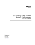
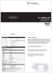
FIGURE 1-1
■
The Sun StorEdge 6320 System - Front View
Capacity – The Sun StorEdge 6320 system supports 36.4-Gbyte, 73.4-Gbyte, and
146.8- Gbyte disk drives in the Sun StorEdge 6020 arrays. The supported capacity
for the Sun StorEdge 6320 system is a minimum of 504 Gbytes and a maximum of
45 Tbytes. Mixed drive sizes are supported.
Note – If mixed drive sizes are used within a storage pool, the lowest drive size
dictates the usable storage of each drive within that volume. For instance, if a
volume of seven disks has six 146 Gbyte disks and one 36 Gbyte disk, all disks will
be viewed as 36 Gbyte disks.
1-2
Sun StorEdge 6320 System 1.2 Reference and Service Manual • January 2004
■
System Redundancy – The systems provide full data path redundancy with no
data path component as a single point of failure, offering 24x7 data availability.
Redundant components include the Fibre Channel switches (if used), Sun
StorEdge 6020 array, and dual power sequencers.
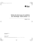
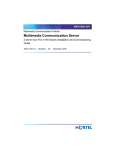
Storage
Service
Processor
Service
Processor
Panel
Service
FIGURE 1-2
■
The Sun StorEdge 6320 System - Rear View
Host Managed Multipathing – The system provides at least two full speed
physical I/O paths to each host. The Sun StorEdge 6020 arrays provide two 2-Gbit
physical I/O paths. Host software is required to manage the I/O multipathing
and load balancing across these I/O paths. Supported software includes Sun
StorEdge Traffic Manager software and VERITAS Dynamic Multipathing (DMP).
Chapter 1
Introduction to the Sun StorEdge 6320 System
1-3
■
Host Support – The Sun StorEdge 6320 system supports the following minimal
level operating systems. Refer to the latest version of the Sun StorEdge 6320 System
Release Notes for the latest support information.
■
Solaris 8, Solaris 9, and later releases
■
Microsoft Windows NT Enterprise Edition 4.0, Service Pack 6
■
■
1-4
Microsoft Windows 2000 Server and Windows 2000 Advanced Server, Service
Pack 2
■
Hewlett Packard HP-UX 11.i and HP-UX 11
■
IBM AIX 4.3.3 (32-bit), AIX 5.1 (32-bit and 64-bit)
■
RED HAT Linux 7.2
Software Support – The Sun StorEdge 6320 system supports several software
packages including the following:
■
Sun StorEdge Remote Response service software (to support optional service)
■
Remote power management
■
Storage Automated Diagnostic Environment
■
SANbox2 Manager
■
Sun StorEdge SAN Foundation software release support
■
Multiple Host Support – Each Sun StorEdge 6020 array HA configuration
supports up to 16 hosts. This enables the Sun StorEdge 6320 system to allow up to
176 hosts with Fibre Channel SAN zoning (this assumes the 2x2 configurations
are used within the system). With integrated Fibre Channel switches, the Sun
StorEdge 6320 systems can provide for direct connectivity of five partner groups
of hosts connections. Additional host connections can be achieved using external
switches.
■
Local or Remote Serviceability – The Sun StorEdge 6320 system includes a
Storage Service Processor. Support for the Sun StorEdge Remote Response service
software is built into the Storage Service Processor. All configurations are Sun
StorEdge Remote Response service ready. Local serviceability and management is
provided by IP Ethernet connectivity to the Storage Service Processor.
■
Hot-Swappable FRUs – The Sun StorEdge 6320 systems use hot-swappable fieldreplaceable units (FRUs). The FRUs include power supplies and cooling units
(PCU), batteries, disk drives, loop cards, RAID controllers FC switches, and
Ethernet hub. Not all FRUs can be replaced by customers. The Storage Service
Processor, Storage Service Processor accessory tray, and the service panel must be
replaced by Sun service personnel. The FC switches, Storage Service Processor,
and Ethernet hub can be replaced without rebooting the Sun StorEdge 6020
arrays.
■
Switched and Switchless Configurations – The Sun StorEdge 6320 systems
provide both a switched and switchless configuration. The internal switched
configuration is delivered with Sun StorEdge Network FC Switch-16 switches. An
external switch configuration can use external switches, supplied by either Sun or
Sun StorEdge 6320 System 1.2 Reference and Service Manual • January 2004
the customer. With a switchless configuration you can directly connect to a data
host without the use of a switch.
Neither the internal or external switches are connected to the system’s internal
LAN. Instead, these switches connect to an outside Ethernet connection.
■
Host Connect Support – The Sun StorEdge 6320 system provides native Fabric
(F-port) host connectivity. Integrated switches also provide for larger host
connectivity.
■
Remote Lights-Out Power Management – The Sun StorEdge 6320 system
supports remote lights-out power management. Power sequencers and a
universal serial bus relay are used to control the power sequencing. This enables
users to remotely shut down the components in the system to save power. The
power down shuts down most of the components in the subsystem. Only the
Storage Service Processor and minimal other components are kept running to
enable a subsequent remote power on operation. Power can be restored remotely
at any time. The remote lights-out power management interface also provides
capability to completely shut down the power to all the components. If power is
completely shut down, it cannot be restored remotely.
■
Online Firmware Upgrades – The Sun StorEdge 6320 system supports online
firmware upgrade of most components. There is 100 percent data availability
during the online firmware upgrade operation. Online upgrade is not supported
on the firmware of the individual disks.
■
Depopulated Drive Support – The Sun StorEdge 6320 system supports having
depopulated drive trays in the Sun StorEdge 6020 trays. Each drive tray can
contain 7 to 14 drives. Slots without drives must have dummy drives inserted in
them.
■
Storage Array Configurations – The Sun StorEdge 6320 system supports
attaching controller-less Sun StorEdge 6020 arrays to existing Sun StorEdge 6020
arrays that have controllers. These controller-less trays are referred to as expansion
units. The naming convention used in configuration is “controller x trays”
(controller by trays). A 2x2 configuration means there are two controllers and two
trays. A 2x4 configuration means there are two controllers and four trays. The Sun
StorEdge 6320 system supports the following configurations:
■
■
Sun StorEdge 6020 HA array with 2x2
■
Sun StorEdge 6020 HA array with 2x4
■
Sun StorEdge 6020 HA array with 2x6
Other Support and Features – Other support and features include:
■
Network Time Protocol (NTP)
■
Simple Network Management Protocol (SNMP)
■
Array-based Common Information Model (CIM) support
■
Sun Indicator Standard support (LED improvement on the enclosure)
■
Dynamic Host Configuration Protocol (DHCP)
Chapter 1
Introduction to the Sun StorEdge 6320 System
1-5
■
■
■
■
■
■
■
TABLE 1-1
Integration with the Sun StorEdge Enterprise Storage Manager software
A maximum of 10 Sun StorEdge 6020 arrays (trays) in the base Sun StorEdge
Expansion Cabinet
A maximum of 22 Sun StorEdge 6020 arrays using the base cabinet and a
second Sun StorEdge Expansion Cabinet
Installation, configuration, and support services (optionally available)
Logical unit number (LUN) security access for the storage consolidation
models
Cluster and simultaneous independent host attach support
Reliability, availability, and serviceability (RAS) features – The Sun StorEdge
6320 systems provide you with the reliability, availability, and serviceability
(RAS) features shown in TABLE 1-1:
RAS Features
Benefits
RAS Features
Serviceability
• Sun Indicator Support (SIS) on enclosure chassis LED (Locator/Fault LED)
• Sun Standard compliant field-replaceable unit identification (FRU ID) support
• Security in the Storage Service Processor to isolate customer LAN
Firmware
reliability and
failure analysis
techniques
•
•
•
•
1-6
Automatic firmware crash dump in exception scenarios
Internal management and diagnostics commands
Real time checkers (RTC) used to reduce panics in firmware
Improved firmware robustness
Sun StorEdge 6320 System 1.2 Reference and Service Manual • January 2004
TABLE 1-1
RAS Features (Continued)
Benefits
RAS Features
Reliability
• Easier insertion and extraction and better locking mechanisms for disks and other
FRUs
• Blind mate connectors to avoid bent pins on FRU insertion
Availability
• Enhanced temperature monitoring to shut down the system only when temperature
thresholds are exceeded
• Automated power and cooling unit (PCU) adjusts fan speed based on the temperature
monitoring
• Improved battery recharge control to avoid missing battery recharge if a Sun StorEdge
6020 array is shut down during battery recharge cycles
• Automated and online firmware upgrade and downgrades
• Hardware integrated device electronics (IDE) interface to introduce cache saving
procedures without adding battery cost as higher density enclosures are developed
Fault detection,
fault isolation, and
failure fencing
• Support for parity on RISC RAM hardware
• Loop card with standard SSC100 management processor and VSC055 serial backplane
controller provides better enclosure management
• Faster and modular loop card serial communication protocol
• Failure fencing (fault containment) in case of hardware failures
• Automatic hardware bypass of the faulty drive should a drive cause loop disruptions
• Hardware support that creates a diagnostics loop of disks for performing background
tests
• Temperature sensors for continuous threshold-based temperature monitoring. The
temperature sensors are located close to heat spots to provide accurate temperature
measurements
• Fibre Channel ECHO ELS support, which allows for both external echo tests (invoked
from the Sun StorEdge 6020 array) and passive echo tests (invoked from the Fibre
Channel switch)
• External and internal loopback test support to test front-end controller and back-end
Fibre Channel ports
• Fibre Channel link status counters for threshold-based analysis of link error statistics
1.1.1
Sun StorEdge 6320 System with Internal Switches
The Sun StorEdge 6320 system has the most capabilities when configured with two
internal switches. With the internal switches, the system can take best advantage of
the it’s management software and can support up to 10 Sun StorEdge 6020 trays in
the first cabinet. By adding a second Sun StorEdge Expansion Cabinet, the Sun
StorEdge 6320 system supports up to 12 additional Sun StorEdge 6020 trays (a total
Chapter 1
Introduction to the Sun StorEdge 6320 System
1-7
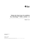
of 22 trays). FIGURE 1-3 illustrates a representation of the Sun StorEdge 6320 system
connections. For a cabinet representation of the Sun StorEdge 6320 system, see
FIGURE 1-5.
1-8
Sun StorEdge 6320 System 1.2 Reference and Service Manual • January 2004
Service Modem
ports
out
FC Ports
Ethernet hub
Storage Service
Processor
Sun StorEdge
Network FC
Switch-16 switches
Ethernet hub
Sun StorEdge
6020 arrays
(partner groups)
Power Grid 1
Power Grid 1
Power Grid 2
Power Grid 2
Sun StorEdge Cabinet
FIGURE 1-3
Additional Sun StorEdge
Expansion Cabinet
Sun StorEdge 6320 System
Chapter 1
Introduction to the Sun StorEdge 6320 System
1-9
1.1.2
Sun StorEdge 6320 Switchless Systems
The Sun StorEdge 6320 systems can be configured without switches. The Sun
StorEdge 6320 switchless configuration system can be directly attached to your host.
Sun provides the following cables and cards for switchless configurations:
1.1.3
■
Prime input power cords (two each) for mounting a pair of third-party switches
in the front end of a Sun StorEdge 6320 system cabinet.
■
For the Sun StorEdge 6320 system, Sun provides FC cable connectivity for up to
22 Sun StorEdge 6020 trays.
Sun StorEdge 6320 System with External Switches
The Sun StorEdge 6320 systems can be configured an external switches.
Note – The Sun-supplied and customer-supplied switches that are installed in a Sun
StorEdge 6320 system cannot be connected to the internal local area network (LAN)
of the system. All Fibre Channel switches must be managed from an outside
Ethernet connection.
Supported Brocade and McData switches can be used with the Sun StorEdge SAN
Foundation software.
Note – The switches in the SAN must be homogeneous (all Sun, all Brocade, or all
McData).
With Sun StorEdge 6320 switchless systems, you are responsible for providing:
■
All host FC cable connections
■
An Ethernet cable connection between any third-party switches (if applicable)
and a storage area network (SAN) maintenance console. The connection is used to
monitor and perform diagnostic reporting.
Neither customer-supplied switches or the Sun-installed external switches are
monitored or diagnosable by the internal Storage Service Processor in the Sun
StorEdge 6320 systems.
1-10
Sun StorEdge 6320 System 1.2 Reference and Service Manual • January 2004
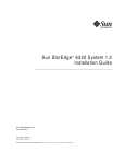
1.2
System Architecture
The basic architecture of the Sun StorEdge 6320 system SAN configuration is shown
in FIGURE 1-4. Note that the Fibre Channel switches are optional. If the switches are
not present, the Sun StorEdge 6020 arrays connect directly to the SAN.
Storage Service
Processor LAN
Customer
LAN
Storage Service
Processor
accessory tray
Storage Area Network
Host interface
(optional)
Fibre Channel switch
Fibre Channel switch
Storage Service
Processor
Ethernet hub
Internal
component
LAN
Sun StorEdge
6020 array
HA Configuration
FIGURE 1-4
Basic Sun StorEdge 6320 System Architecture
Chapter 1
Introduction to the Sun StorEdge 6320 System
1-11
1.3
System-Level Support Information
TABLE 1-2 shows Sun StorEdge 6320 system information.
TABLE 1-2
Sun StorEdge 6320 System-Level Configurations
System
Sun StorEdge 6320 system
Bandwidth1
4400 Mbytes/sec maximum
Capacity2
504 Gbytes to 45 Tbytes
Maximum Host
Connectivity3
5 (with integrated switches)
88 (with external switches)
Maximum LUNs
704 (64 per Sun StorEdge 6020 array)
LUN Masking
Yes
1 - Bandwidth is defined as the theoretical maximum using full-duplex Fibre Channel connections.
2 - Minimum capacity is calculated using 36-Gbyte drives, and maximum capacity is calculated using 146.8-Gbyte
drives. The available data capacity using default configurations are slightly lower due to capacity used for parity
and hot spares.The minimum size is 10 Mbyte for all LUNs. The maximum size is 2 Tbytes for all LUNs.
3 - All host connections are redundant partner groups.
1.4
Hardware Descriptions
The hardware building blocks for the Sun StorEdge 6320 system include:
1-12
■
Service Processor Panel
■
Storage Service Processor
■
Customer management connection
■
Storage devices
■
Ethernet hub
■
FC switches
■
Storage Service Processor accessory tray
■
Sun StorEdge expansion cabinet
Sun StorEdge 6320 System 1.2 Reference and Service Manual • January 2004
1.4.1
Service Processor Panel
The Service Processor Panel simplifies the cabling to the system. You can connect
your cables to these accessible panel connections rather than to individual
components of the system.
1.4.2
Storage Service Processor
The Storage Service Processor is a Sun Fire™ V100 server. The Sun Fire server
provides a 550-MHz, 64-bit UltraSPARC® IIe processor, 512 Gbytes of memory, a 40
Gbyte IDE internal drive, a CD-ROM drive, and a universal serial bus (USB) flash
disk to save the Storage Service Processor personality data.
The hot-swappable USB flash disk provides 16 Mbyte of removable storage. The USB
flash disk enables you to restore the Storage Service Processor personality files (for
example, /etc/ethers). The data can be restored in the event of a Storage Service
Processor failure.
Every Storage Service Processor is configured with the same hardware and software
components to ensure ease of replacement. All Storage Service Processors have built
in hardware and software support for the Sun StorEdge Remote Response service
utility.
The Storage Service Processor supports health monitoring and fault mitigation
independent of the customer’s server. There is no data path connectivity, thus the
unit is not a mission-critical component.
Customers use a web interface or a command-line interface to perform functions on
the Storage Service Processor.
Chapter 1
Introduction to the Sun StorEdge 6320 System
1-13
1.4.3
Customer Management Connection
The customer management connection is a dedicated Ethernet connection that
connects to the designated Storage Service Processor. Each Storage Service Processor
serves as the master for collecting data from its Sun StorEdge 6320 system. This
connection is also referred to as the customer LAN. If more than one Sun StorEdge
6320 system is connected to the customer management connection, alert traffic will
be passed across the LAN. The traffic consists of monitoring data that reflects the
overall health as well as specific alerts that may occur within the Sun StorEdge 6320
system.
1.4.4
Storage Devices
The Sun StorEdge 6020 arrays provide backend data storage inside the Sun StorEdge
6320 system. Each Sun StorEdge 6020 array supports 36 Gbyte, 73 Gbyte, or 146
Gbyte disk drives.
In factory-configured systems, the Sun StorEdge 6020 arrays are configured with one
storage pools per Sun StorEdge 6020 tray. Each tray contains a full-capacity RAID 5
(6 or 13 disks) storage pool with a segment size of 16 Kbytes and is configured with
one standby hot spare.
Utilities are provided on the Storage Service Processor that enable users to
reconfigure the Sun StorEdge 6020 arrays to meet workload performance
requirements.
The following features are available on a Sun StorEdge 6320 system:
■
Volume support – You can create up to 64 volumes (also called LUNs) from a
storage pool per storage array.
■
LUN access control – This restricts host HBA access to the volumes.
The RAID levels supported on the Sun StorEdge 6320 system configurations are:
1-14
■
RAID 0 – A volume that arranges data across one or more components. Striping
alternates equally-sized segments of data across two or more components,
forming one logical storage unit. These segments are interleaved round-robin, so
that the combined space is made alternately from each component, in effect,
shuffled like a deck of cards. Striping enables multiple controllers to access data
at the same time, which is also called parallel access. Parallel access can increase
I/O throughput because all disks in the volume are busy most of the time
servicing I/O requests.
■
RAID 1 – This version of RAID 1 is considered to be RAID 1+0. Each data block in
a RAID 1 volume is mirrored on two physical drives. If one of the mirrored pair
fails, the data from the other drive is used. Because the data is mirrored in a RAID
Sun StorEdge 6320 System 1.2 Reference and Service Manual • January 2004
1 configuration, the volume has only half the capacity of the assigned drives. For
example, if you create a 4-drive RAID 1 volume with 36 Gbyte drives, the
resulting data capacity is 4 x 36 / 2 = 72 Gbytes.
■
1.4.5
RAID 5 – In a RAID 5 configuration, data is striped across the drives in the
volumes in segments, with parity information being striped across the drives, as
well. Because of this parity, if a single drive fails, data can be recovered from the
remaining drives. Two drive failures in the same storage pool cause all data to be
lost. A RAID 5 volume has the data capacity of all the drives in the logical unit,
less one. For example, a five-drive RAID 5 volume with 73 Gbyte drives has a
capacity of (5 - 1) x 73 = 292 Gbytes.
Ethernet Hub
The Sun StorEdge 6320 system uses an Ethernet hub as the backbone for the internal
service network. The allocation of Ethernet ports is as follows:
1.4.6
■
One for the Storage Service Processor (per system)
■
Two for each Sun StorEdge 6020 array partner group
■
One for the Ethernet hub that is installed in the second Sun StorEdge Expansion
Cabinet in the Sun StorEdge 6320 or 6320 switchless systems (if the second
cabinet is used)
Fibre Channel Switches
The Sun StorEdge network 2 Gbit Fibre Channel switch-16 switch provides cable
consolidation and increased connectivity. The Sun StorEdge network FC switch-16
switches are used for the internal data interconnection infrastructure.
The switches are paired to provide data path redundancy. Two switches are used in
each Sun StorEdge 6320 system.
These switches can be monitored through the SANbox2 Manager GUI.
These switches are configured using the Sun StorEdge Configuration Service
software, which is installed on the customer’s host. These are discussed in “Sun
StorEdge Configuration Service Software” on page 1-18 and “Managing the System”
on page 2-1.
The Sun StorEdge 6320 switchless system will not have switches present.
Chapter 1
Introduction to the Sun StorEdge 6320 System
1-15
1.4.7
Storage Service Processor Accessory Tray
The Storage Service Processor accessory tray is an enclosure that contains all the
components necessary to support the Sun StorEdge Remote Response service
software. This enclosure simplifies serviceability, as the entire unit is an FRU.
The Storage Service Processor accessory tray contains the following:
1.4.8
■
Serial Network Terminal Concentrator (NTC) used for remote serviceability
support
■
Ethernet router/firewall used to provide additional security to Sun from the
customer management LAN
■
Personal Computer Memory Card International Association (PCMCIA)
compatible modem
■
A single AC power supply used by all components in the tray
Sun StorEdge Expansion Cabinet
The Sun StorEdge 6320 system is packaged in the Sun StorEdge Expansion Cabinet,
which is also used for several other Sun products. The customer-accessible areas of
the system are clearly labeled. Service-accessible areas of the system are clearly
labeled as such. All physical configurations will be completed by Sun-trained
personnel. Customers not trained for service by Sun will have significantly limited
access to the physical layout of the system.
1.5
Software Descriptions
The software included with the Sun StorEdge 6320 system is:
■
Solaris 9 operating environment
■
Sun StorEdge Configuration Service software:
■
web interface
■
command line interface (CLI) - sscs(1M)
Additionally, the Sun StorEdge 6320 systems support several software packages,
including the following:
1-16
■
Sun StorEdge Remote Response service software (to support optional service)
■
Remote power management
■
Storage Automated Diagnostic Environment (system edition)
Sun StorEdge 6320 System 1.2 Reference and Service Manual • January 2004
■
SANbox2 Manager
■
Sun StorEdge SAN Foundation software release support
Note – The above software packaged with the Sun StorEdge 6320 system is not
meant for use on the data host servers.
1.5.1
Solaris 9 Operating System
A customized version of the Solaris 9 operating system is installed on the Storage
Service Processor.
1.5.2
Sun StorEdge Remote Response Software
The Sun StorEdge Remote Response service software is included on all Sun StorEdge
6320 systems. Sun StorEdge Remote Response service software provides “phone
home” capability and dial-back access by Sun. This enables Sun storage experts to
remotely troubleshoot, diagnose, and service the Sun StorEdge 6320 system.
The features of Sun StorEdge Remote Response service include:
1.5.3
■
Early fault detection
■
Fast response and reaction to alerts and alarms
■
Remote troubleshooting, diagnosis, and repair
■
Increased system availability
■
Reduced cost of ownership
Remote Power Management
The Sun StorEdge 6320 system is equipped with the hardware and software
necessary to support a remote power on. When enabled, a system administrator can
turn the power sequencer on and off either locally or remotely using the Sun
StorEdge 6320 system’s Sun StorEdge Configuration Service software.
The default mode for the Sun StorEdge 6320 system control management is for all
Sun StorEdge 6320 system configurations to have the remote power on software
disabled.
Chapter 1
Introduction to the Sun StorEdge 6320 System
1-17
To use the remote power off mode, you must configure the cabinets for this
operation. Once configured, the Storage Service Processor detects the presence of the
relay board and enables two additional functions in the rack control management
software. The modes are:
■
Local power on (powering on the Sun StorEdge 6320 system at the system)
■
Remote power on (powering on the system either locally or remotely)
These modes are used to logically shut down the Sun StorEdge 6020 arrays and
instruct the power sequencers to remove power from those components.
The configuration information for the lights-out setup is in the Sun StorEdge 6320
Installation Guide.
Note – During these modes, the Storage Service Processor and the Storage Service
Processor accessory tray remain powered and active to provide control over the
power relay board.
Note – Do not use the remote power-off mode when moving the cabinets to a
different location. You must use the complete power-down procedure before moving
the cabinets.
1.5.4
Sun StorEdge Configuration Service Software
The Sun StorEdge Configuration Service software enables you to configure and
manage the Sun StorEdge 6320 systems. The software is available for use through a
web-browser interface and the command-line interface (CLI) sscs(1M).
The CLI provides a remote client command-line interface that enables you to invoke
sscs commands to administer the Sun StorEdge 6320 system. This interface is not a
telnet(1) session.
All software features are available through the web interface and CLI; you can use
either interface to manage volumes, storage pools, volume groups, initiator groups,
storage trays, and the Storage Service Processor.
1-18
Sun StorEdge 6320 System 1.2 Reference and Service Manual • January 2004
1.5.5
Storage Automated Diagnostic Environment
The Storage Automated Diagnostic Environment is a distributed online health and
diagnostic monitoring tool. A special host version is customized to use with the Sun
StorEdge 6320 system. It can be configured to monitor on a 24-hour basis, collecting
information that enhances the reliability, availability, and serviceability (RAS) of the
storage devices.
The Storage Automated Diagnostic Environment offers the following features:
1.5.5.1
■
A web-based user interface for device monitoring and diagnostics
■
Distributed test invocation by means of lists or topology. You can run the tests
through the Storage Automated Diagnostic Environment GUI or through the
command-line interface (CLI).
■
Topology grouping for multi-level hosts and components
■
Revision updates
■
Support for the Storage Service Processor and components of Sun StorEdge 6320
system
■
Remote notification through Sun StorEdge Remote Response
■
Role-based access
■
Service utilities
■
Encryption through a Secure Socket Layer (SSL) protocol to protect transmitted
information.
Diagnostic Functionality
Diagnostic tests have been integrated into the Storage Automated Diagnostic
Environment for device diagnostics and FRU isolation. Each test can be run
individually from the command line or from the Storage Automated Diagnostic
Environment user interface.
The Storage Automated Diagnostic Environment Diagnostic tests are described in
the Storage Automated Diagnostics Environment 2.2 System Edition User’s Guide.
1.5.6
SANbox2 Manager
The SANbox2 Manager software is supported on the Sun StorEdge 6320 systems.
Chapter 1
Introduction to the Sun StorEdge 6320 System
1-19
SANbox2 Manager is a GUI consisting of menus, buttons, and pages (screen
windows) that you can use to easily manage switches from a server running
supported Solaris, Linux, or Windows operating systems. Using SANbox2 Manager,
you can view and change network, switch, and port configuration for one or more
Fabrics concurrently.
SANbox2 Manager displays the most current Fabric information. When a Fabric
changes, the new Fabric information is sent to the workstation and is reflected in the
SANbox2 Manager window.
SANbox2 Manager enables you to perform the following procedures:
■
Display multiple fabrics
■
Associate the switch management interface with its IP network configuration
parameters
■
View the FC connection
■
View hardware and firmware version information for the selected chassis
■
View switch names and worldwide names (WWNs)
■
View port addresses on the selected chassis
The SANbox2 Manager Help menu contains information about the product and a
complete online help guide.
1.5.7
Sun StorEdge SAN Foundation Software Release
Support
The Sun StorEdge SAN Foundation software (version 4.2 or later) is supported for
the Sun StorEdge 6320 systems for use with data hosts using the Solaris operating
systems. (Sun StorEdge Traffic Manger can be used with data hosts running other
operating systems.) The Sun StorEdge SAN Foundation release is Sun’s latest full
Fabric, open heterogeneous SAN featuring support for the following:
1-20
■
Sun 2 Gbit HBAs and switches
■
Sun StorEdge 6020 array
■
Brocade SilkWorm 16-port 2 Gbit 3800 FC switch, SilkWorm 64-port, 2 Gbit 12000
Fibre Channel Core Fabric Switch, and McData Intrepid 6064 Director
■
Storage Automated Diagnostic Environment
■
Sun StorEdge Diagnostic Expert software
■
Sun StorEdge Enterprise Storage Manager 1.2 software
■
Sun StorEdge Resource Manager Suite 6.0
■
Sun StorEdge Availability Suite 3.1
■
Sun StorEdge Traffic Manager
Sun StorEdge 6320 System 1.2 Reference and Service Manual • January 2004
■
Sun StorEdge Performance Suite
■
Sun StorEdge Utilization Suite Software
■
VERITAS file system (VxFS)
■
VERITAS NetBackup
■
VERITAS Volume Manager (VxVM)
■
Solstice Backup
■
Solaris Logical Volume Manager
■
Support for open heterogeneous SANs with Fabric support for Linux, Windows
NT 4.0, Windows 2000, HP/UX and IBM AIX based servers
■
Support for large, complex SANs with support for up to 7 inter-switch hops, up
to 64 switches, and both core Fabric switches and directors
Chapter 1
Introduction to the Sun StorEdge 6320 System
1-21
1.6
Default System Configurations and
Settings
This section presents information about default Sun StorEdge 6320 system
configurations. The information includes all settings for the Sun StorEdge 6020
arrays, Sun StorEdge network Fibre Channel switches, and IP address settings.
This section is organized as follows:
1-22
■
“Sun StorEdge 6320 System Layout” on page 1-23
■
“Sun StorEdge 6020 Array and 6320 System Settings” on page 1-24
■
“Sun StorEdge Network FC Switch Settings” on page 1-27
■
“IP Address Settings” on page 1-29
Sun StorEdge 6320 System 1.2 Reference and Service Manual • January 2004
1.6.1
Sun StorEdge 6320 System Layout
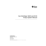
FIGURE 1-5 shows the layout (back view) of the hardware components in a Sun
StorEdge 6320 system that has two cabinets. The Sun StorEdge 6320 switchless
system has the same layout, without the FC switches (sw1a and sw1b).
Second Cabinet
First Cabinet
Storage Service Processor
Accessory Tray (firewall)
Ethernet Hub
Blank
FC Switch (sw1)
FC Switch (sw2)
array15
array04
array14
Ethernet
Hub
array03
array13
array02
array12
array01
array11
array00
array10
Power Sequencer
Power Sequencer
FIGURE 1-5
Back View of the Sun StorEdge 6320 System
Chapter 1
Introduction to the Sun StorEdge 6320 System
1-23
1.6.2
Sun StorEdge 6020 Array and 6320 System
Settings
The default supported configurations for the Sun StorEdge 6020 arrays and Sun
StorEdge 6320 systems are shown in TABLE 1-3.
TABLE 1-3
Default 6320 System Configuration
Element
Sun StorEdge 6020 and 6320 System1
Hot Spare (one per tray)
Yes
Block Size
16 Kbytes
Cache
auto
Mirror
auto
Failover Mode (mp_support)
Explicit LUN failover
Read Ahead (rd_ahead)
on
Recon Rate
med
RAID Type
5 (with hot spare)
Disk Scrubbing
enabled
Storage Pool/Tray
1
Configured Volumes/Trays2
0
1. All Sun StorEdge 6020 arrays ship from the factory in the specified default configuration.
2. All Sun StorEdge 6020 arrays are shipped with no LUNs configured. Volume slicing is always enabled and
cannot be disabled. LUNs will be configured on the Sun StorEdge 6320 arrays at the customer site to meet the
customer requirements.
1-24
Sun StorEdge 6320 System 1.2 Reference and Service Manual • January 2004
The default Sun StorEdge 6020 array target IDs and host names are shown in
TABLE 1-4. This information only applies if the Sun StorEdge 6320 system is being
used in an arbitrated loop configuration. Fabric configurations do not use array
target ID information.
TABLE 1-4
Default Sun StorEdge 6020 Array Target ID and Host Name
Sun StorEdge 6020 Array
Target ID
Host Name
array00
0, 1
array00
array01
2, 3
array01
array02
4, 5
array02
array03
6, 7
array03
array04
8, 9
array04
array10
10, 11
array10
array11
12, 13
array11
array12
14, 15
array12
array13
16, 17
array13
array14
18, 19
array14
array15
20, 21
array15
The Sun StorEdge 6020 array command configuration settings are given in
TABLE 1-5.
TABLE 1-5
Sun StorEdge 6020 Array Set Command Configuration Settings
Parameter
Default Value
bootmode
auto
bootdelay
3
sn
nnnnnn
ip
See TABLE 1-10
netmask
255.255.255.0
gateway
0.0.0.0
tftphost
0.0.0.0
tftpfile
<NULL>
hostname
<NULL> for the Sun StorEdge 6020 arrays
vendor
0301
Chapter 1
Introduction to the Sun StorEdge 6320 System
1-25
TABLE 1-5
Sun StorEdge 6020 Array Set Command Configuration Settings (Continued)
Parameter
Default Value
model
501-5710-00(50) (Can change with board revisions)
revision
300 (Can change with firmware revisions)
logto
*
loglevel
3
rarp
on
mac
n:n:n:n:n:n
The command configuration settings for the Sun StorEdge 6020 array system list are
shown in TABLE 1-6.
TABLE 1-6
1-26
Sun StorEdge 6020 Array System Commands Default Configuration
Parameter
Default Value
blocksize
16 Kbytes
cache
auto
mirror
auto
mp_support
mpxio
rd_ahead
on
recon_rate
med
disk_scrubbing
enabled
sys_memsize
256 Mbytes
cache_memsize
1024 Mbytes
enable_volslice
on
fc_topology
auto
fc_speed
auto cable
loop1_split
auto
naca
off
Sun StorEdge 6320 System 1.2 Reference and Service Manual • January 2004
The Sun StorEdge 6020 array miscellaneous configuration parameters are shown in
TABLE 1-7.
TABLE 1-7
1.6.3
Sun StorEdge 6020 Array Miscellaneous Configuration Parameters
Parameter
Default Value
vol init
rate = 16
vol verify
rate = 1
port host
sun
Sun StorEdge Network FC Switch Settings
This section presents a series of tables that provide information about the default
settings for the Sun StorEdge network FC switch-16 switches that come factory
installed in the Sun StorEdge 6320 system. The following information is included in
this subsection:
■
Sun StorEdge network FC switch-16 parameters
■
Sun StorEdge 6320 system switch configuration
The Sun StorEdge network FC switch-16 parameters are given in TABLE 1-8.
TABLE 1-8
Sun StorEdge Network FC Switch-16 Parameters
Field
Value
Default Ethernet Address
10.0.0.1
Operational State
Online
Principal Switch Role
FALSE
Chassis Type
SANbox2 16-port switch
Flash
1.n.n
PROM Version
0.4.n.n
DOMAIN ID
1 (sw1)
2 (sw2)
Port Properties
Port State
Online
1 Gbyte/2 Gbyte Transfer Rate
Auto-detect
Multi-frame Sequence (MFS)
Bundling Enabled
FALSE
Chapter 1
Introduction to the Sun StorEdge 6320 System
1-27
TABLE 1-8
Sun StorEdge Network FC Switch-16 Parameters (Continued)
Field
Value
ExtCredit
0
TOVs
edtov
2000
mfstov
0
ratov
10000
rttov
100
Network Properties
IP Mask
255.255.255.0
Gateway Address
0.0.0.0
Discovery
Static
Security Enable
FALSE
SNMP
Trap Authentication
FALSE
SNMP Location
<Undefined>
SNMP Contact
<Undefined>
The default Sun StorEdge 6320 system switch configuration is given in TABLE 1-9.
TABLE 1-9
1-28
Sun StorEdge 6320 System Switch Configuration
sw1
sw2
Port 0 = G-Port (Host#1a)
Port 0 = G-Port (Host#1b)
Port 1 = G-Port (Host#2a)
Port 1 = G-Port (Host#2b)
Port 2 = G-Port (Host#3a)
Port 2 = G-Port (Host#3b)
Port 3 = G-Port (Host#4a)
Port 3 = G-Port (Host#4b)
Port 4 = G-Port (Host#5a)
Port 4 = G-Port (Host#5b)
Port 5 = G-Port (array00 master)
Port 5 = G-Port (array00 altmaster)
Port 6 = G-Port (array01 master)
Port 6 = G-Port (array01 altmaster)
Port 7 = G-Port (array02 master)
Port 7 = G-Port (array02 altmaster)
Port 8 = G-Port (array03 master)
Port 8 = G-Port (array03 altmaster)
Port 9 = G-Port (array04 master)
Port 9 = G-Port (array04 altmaster)
Port 10 = G-Port (array10 master)
Port 10 = G-Port (array10 altmaster)
Sun StorEdge 6320 System 1.2 Reference and Service Manual • January 2004
TABLE 1-9
1.6.4
Sun StorEdge 6320 System Switch Configuration (Continued)
sw1
sw2
Port 11 = G-Port (array11 master)
Port 11 = G-Port (array11 altmaster)
Port 12 = G-Port (array12 master)
Port 12 = G-Port (array12 altmaster)
Port 13 = G-Port (array13 master)
Port 13 = G-Port (array13 altmaster)
Port 14 = G-Port (array14 master)
Port 14 = G-Port (array14 altmaster)
Port 15 = G-Port (array15 master)
Port 15 = G-Port (array15 altmaster)
IP Address Settings
The IP addressing configurations are given in TABLE 1-10.
TABLE 1-10
IP Addressing Configurations
IP Address
Designator
Description
127.0.0.1
localhost
Standard UNIX loopback
192.168.0.2
sp
dmfe 1 Ethernet port log host
192.168.0.40
array00
Lowest Sun StorEdge 6020 arrays in first cabinet
192.168.0.41
array01
Second Sun StorEdge 6020 arrays in first cabinet
192.168.0.42
array02
Third Sun StorEdge 6020 arrays in first cabinet
192.168.0.43
array03
Fourth Sun StorEdge 6020 arrays in first cabinet
192.168.0.44
array04
Fifth Sun StorEdge 6020 arrays in first cabinet
192.168.0.50
array10
Lowest Sun StorEdge 6020 arrays in second cabinet
192.168.0.51
array11
Second Sun StorEdge 6020 arrays from bottom in
second cabinet
192.168.0.52
array12
Third Sun StorEdge 6020 arrays from bottom in second
cabinet
192.168.0.53
array13
Fourth Sun StorEdge 6020 arrays from bottom in
second cabinet
192.168.0.54
array14
Fifth Sun StorEdge 6020 arrays from bottom in second
cabinet
192.168.0.55
array15
Sixth Sun StorEdge 6020 arrays from bottom in second
cabinet
Chapter 1
Introduction to the Sun StorEdge 6320 System
1-29
The numbering scheme used to calculate the IP addresses depends on the Sun
StorEdge 6320 system ID number. If the Sun StorEdge 6320 system firewall is
10.0.0.n, the Storage Service Processor IP address is 10.0.0.n+8, and the IP address for
the Storage Service Processor accessory tray will be 10.0.0.n+1. The LAN IP
addresses for the first eight Sun StorEdge 6320 systems shipped to the same site are
listed in TABLE 1-11.
TABLE 1-11
1-30
Storage Service Processor LAN IP Addresses
IP Address
Designator
Description
10.0.0.242
new_firewall
Default factory address for the Sun StorEdge 6320
system firewall
10.0.0.243
new_ntc
Default factory address for the Network Terminal
Concentrator (NTC), which is inside the Storage
Service Processor accessory tray
10.0.0.250
new_sp new_sp.
Default factory address for the Storage Service
Processor
10.0.0.2
sp0-firewall
First Sun StorEdge 6320 system firewall
10.0.0.3
sp0-ntc
First Storage Service Processor accessory tray (NTC)
10.0.0.10
sp0 sp0.
First Storage Service Processor
10.0.0.12
sp1-firewall
Second Sun StorEdge 6320 system firewall
10.0.0.13
sp1-ntc
Second Storage Service Processor accessory tray
(NTC)
10.0.0.20
sp1 sp1.
Second Storage Service Processor
10.0.0.22
sp2-firewall
Third Sun StorEdge 6320 system firewall
10.0.0.23
sp2-ntc
Third Storage Service Processor accessory tray (NTC)
10.0.0.30
sp2 sp2.
Third Storage Service Processor
10.0.0.32
sp3-firewall
Fourth Sun StorEdge 6320 system firewall
10.0.0.33
sp3-ntc
Fourth Storage Service Processor accessory tray
(NTC)
10.0.0.40
sp3 sp3.
Fourth Storage Service Processor
10.0.0.42
sp4-firewall
Fifth Sun StorEdge 6320 system firewall
10.0.0.43
sp4-ntc
Fifth Storage Service Processor accessory tray (NTC)
10.0.0.50
sp4 sp4.
Fifth Storage Service Processor
10.0.0.52
sp5-firewall
Sixth Sun StorEdge 6320 system firewall
10.0.0.53
sp5-ntc
Sixth Storage Service Processor accessory tray (NTC)
10.0.0.60
sp5 sp5.
Sixth Storage Service Processor
Sun StorEdge 6320 System 1.2 Reference and Service Manual • January 2004
TABLE 1-11
1.7
Storage Service Processor LAN IP Addresses (Continued)
IP Address
Designator
Description
10.0.0.62
sp6-firewall
Seventh Sun StorEdge 6320 system firewall
10.0.0.63
sp6-ntc
Seventh Storage Service Processor accessory tray
(NTC)
10.0.0.70
sp6 sp6.
Seventh Storage Service Processor
10.0.0.72
sp7-firewall
Eighth Sun StorEdge 6320 system firewall
10.0.0.73
sp7-ntc
Eighth Storage Service Processor accessory tray
(NTC)
10.0.0.80
sp7 sp7.
Eighth Storage Service Processor
Remote Service Options
This section describes the remote service configuration options associated with
supported Sun StorEdge 6320 system configurations.
This chapter is organized as follows:
■
“Standalone Without Remote Service” on page 1-32
■
“Remote Service to a Single Unit” on page 1-33
■
“Remote Service to Multiple Units” on page 1-34
Chapter 1
Introduction to the Sun StorEdge 6320 System
1-31
1.7.1
Standalone Without Remote Service
A standalone Sun StorEdge 6320 system can be configured without remote service.
In a standalone configuration without remote service option, the Storage Service
Processor must be configured as a master service processor.
Application
Server (Host)
Customer LAN
Storage Service Processor
Storage Service
Processor LAN
Router/Hub
NTC
WAN
Modem
Storage Service
Processor
accessory tray
Sun StorEdge
6320 System
FIGURE 1-6
Standalone Sun StorEdge 6320 System With No Remote Service
The features supported in this configuration are:
1-32
■
Storage Automated Diagnostic Environment
■
Local or host access to monitoring, component management, and alerts
■
One customer LAN address for each Sun StorEdge 6320 system
■
Storage Service Processor serviceability using the console connection (NTC)
■
Host access through the Storage Service Processor by way of one customer LAN
address to the Storage Automated Diagnostic Environment software
Sun StorEdge 6320 System 1.2 Reference and Service Manual • January 2004
1.7.2
Remote Service to a Single Unit
This configuration offers remote service to a single Sun StorEdge 6320 system.
Application
Server (Host)
Customer LAN
Storage Service Processor
Storage Service
Processor LAN
Router/Hub
NTC
WAN
Modem
Phone
Connection
Storage Service
Processor
accessory tray
Sun StorEdge
6320 System
FIGURE 1-7
Remote Service to a Single Sun StorEdge 6320 System
For security reasons, inbound telnet(1) and ftp(1) connections to the Storage
Service Processor have been disabled.
The features supported in this configuration are:
■
Storage Automated Diagnostic Environment
■
Remote services by phone connection
■
Exported product telemetry data stream
■
Storage Service Processor serviceability using the console connection (NTC)
■
Host access through the Storage Service Processor by way of one customer LAN
address to the Storage Automated Diagnostic Environment software
Chapter 1
Introduction to the Sun StorEdge 6320 System
1-33
1.7.3
Remote Service to Multiple Units
This configuration offers remote service to multiple Storage Service Processors in the
configuration. Aggregation is only supported on the Storage Service Processor LAN
for remote connectivity purposes.
Application
Server (Host)
Customer LAN
Storage Service Processor
Storage Service Processor
Storage Service Processor
Router/Hub
Router/Hub
Router/Hub
NTC
WAN
Modem
NTC
WAN
Modem
NTC
WAN
Modem
Phone
Connection
Sun StorEdge
6320 System
Sun StorEdge
6320 System
Storage Service
Processor LAN
FIGURE 1-8
Sun StorEdge
6320 System
Storage Service
Processor LAN
Remote Service to Multiple Sun StorEdge 6320 Systems
Supported features in this configuration are:
1-34
■
Storage Automated Diagnostic Environment
■
Remote services
■
Exported product telemetry data stream
■
Storage Service Processor serviceability using a NTC connection
■
Host access through the Storage Service Processor by way of one customer LAN
to address or Storage Service Processor LAN
■
Aggregation of Storage Service Processors for remote service and alert/telemetry
Sun StorEdge 6320 System 1.2 Reference and Service Manual • January 2004
CHAPTER
2
Managing the System
This chapter provides instructions for using the web interface of the Sun StorEdge
Configuration Service software to configure the various components of the Sun
StorEdge 6320 systems.
This chapter is organized by task. You can also refer to the software’s online help,
which is organized by menu. Also, the initial configuration of the Sun StorEdge 6320
system is documented in the Sun StorEdge 6320 System 1.2 Installation Guide.
Refer to Appendix A for information about using the Sun StorEdge Configuration
Service command-line interface, sscs.
This chapter is organized as follows:
2.1
■
“Overview of the Software” on page 2-1
■
“Using the Software” on page 2-2
Overview of the Software
The Sun StorEdge Configuration Service software enables you to configure and
manage the Sun StorEdge 6320 systems.
Using this software, you can:
■
Manage users who can use the software
■
Configure the network interface (customer LAN)
■
Set the email contact address
■
Manage the arrays
■
Manage storage profiles
■
Create initiators and optionally add initiators to a group
■
Create initiator groups and add initiators to a group
2-1
■
Create volume groups
■
Create a volume, set the LUN number, and add it to a volume group
■
Manage remote power operation
Note – The software of the software includes wizards that help simplify the tasks of
creating volumes, volume groups, storage pools, and initiators.
2.2
Using the Software
You can log in through the following supported browsers:
■
Netscape Navigator™, minimum revision level 4.79 (Netscape version 6 or 7 is
preferred). If time-out conditions become an issue, update your browser to a
version that supports HTTP 1.1 (Netscape 6 or higher).
■
Microsoft Internet Explorer, minimum revision level 5.0
You can manage the system components and related system network features. The
software also enables you to launch the Storage Automated Diagnostic Environment
software application. This application provides fault management and health
reporting for Sun storage devices.
You can perform the following by clicking the labeled tabs:
2-2
■
“Accessing Help” on page 2-3
■
“Logging In and Out” on page 2-3
■
“Administering Users” on page 2-6
■
“Configuring System Settings” on page 2-8
■
“Managing Jobs” on page 2-13
■
“Managing Arrays” on page 2-14
■
“Managing Storage Profiles” on page 2-27
■
“Managing Storage Pools” on page 2-31
■
“Managing Array Volumes” on page 2-37
■
“Managing Volume Groups” on page 2-40
■
“Managing Initiators and Initiator Groups” on page 2-43
■
“Viewing System Reports and Logs” on page 2-49
Sun StorEdge 6320 System 1.2 Reference and Service Manual • January 2004
2.2.1
Accessing Help
A Help button is available at the top right-hand side of the Content frame on every
page. Choose the Help button (FIGURE 2-1) to access detailed procedural help for
configuring and managing your system.
FIGURE 2-1
2.2.2
Accessing the Online Help
Logging In and Out
The following procedures describe how to log in and out of the software. Only users
with passwords on the Storage Service Processor can log in. See TABLE 2-1 for the
supported Storage Service Processor login and default passwords.
TABLE 2-1
Default Storage Service Processor Users and Initial Passwords
User
Initial Password
admin
!admin
storage
!storage
guest
!guest
Chapter 2
Managing the System
2-3
The interface supports both secure and non-secure connections through the
following default ports:
2.2.2.1
■
9080 - Use this HTTP port for non-secure access
■
9443 - Use this HTTPS port for secure access, especially if you are concerned
about password security
Logging In
1. Open a web browser such as Netscape Navigator.
2. Type one of the following URLs:
■
For a non-secure HTTP server connection:
http://ip_address:9080/
Where ip_address represents the IP address of the Sun StorEdge 6320 system (for
example, 10.1.1.12), and port 9080 represents the non-secure port number for
Configuration services.
■
For a secure HTTPS server connection:
https://ip_address:9443/
Where ip_address represents the IP address of the Sun StorEdge 6320 system (for
example, 10.1.1.12), and port 9443 represents the secured port number for
Configuration services.
The Login page is displayed.
3. Log in as admin:
User Name: admin
Password: !admin
Note – To change storage configuration after completing the administrative tasks,
you will have to logout and log back in as a storage user.
4. Choose Log In.
The Admin > General page is displayed, as shown in FIGURE 2-2.
2-4
Sun StorEdge 6320 System 1.2 Reference and Service Manual • January 2004
FIGURE 2-2
2.2.2.2
The Administration > General Screen
Logging Out
● Choose Log Out from any page.
Chapter 2
Managing the System
2-5
2.2.3
Administering Users
This section describes how to manage users and their access rights to the software.
The Sun StorEdge 6320 systems are configured with the three user accounts shown
in TABLE 2-2. The software enables you to set passwords for the accounts. As the
admin user, you authorize users to access the software and system. The user
accounts are as follows:
TABLE 2-2
User Accounts
User Account
Description
admin
An admin user has all administration privileges. The admin user
can modify system attributes on the Administration page and set
passwords for the accounts.
storage
A storage user can use most of the software features related to
storage device configuration. The Administration page is available
to this user as read-only; this user cannot modify admin settings.
This user can use the features available from the Array Management
and Storage Access pages.
guest
A guest has read-only privileges and can view the information in
the software pages. This user cannot modify any settings or features.
The Passwords link on the Administration page enables you to set passwords for the
three user accounts that are allowed to access the software. Once added, a user can
log in to the software using the admin, storage, or guest user name and
password.
Note – See
2.2.3.1
TABLE 2-1 for user account passwords.
Creating or Modifying a User Password
1. Choose the Passwords link on the Administration page.
2. Type a new password in the Enter New Password and Confirm New Password
fields for the user type you want.
3. Choose Save.
2-6
Sun StorEdge 6320 System 1.2 Reference and Service Manual • January 2004
2.2.3.2
Adding Event Email Notifications
The Notifications page displays a table that summarizes the categories of events that
have occurred in the system. You can display details about an event by clicking a
link in the Event Category column.
The page that is displayed enables you to manage the email notification list. The
system sends event information, such as when volumes have been deleted, when
storage pools are created, and so on, to users whose email address you type.
Email Event subscribers can receive “All” events, events from an individual
category, or just a single event.
1. Choose Notifications at the Administration tab.
You can add “All” category subscribers here in the New Subscription section. Type
email addresses, separating each address you type with a comma character (,).
2. Choose an Event Category link in the table.
You can add individual category subscribers here in the New Subscription section.
Type email addresses, separating each address you type with a comma character (,).
3. Choose an Event Name in the Event Category Detail section.
You can add single event category subscribers here in the New Subscription section.
Type email addresses, separating each address you type with a comma character (,).
4. Choose Add.
2.2.3.3
Removing Event Email Notifications
1. Choose Notifications at the Administration tab.
2. Choose an Event link in the table.
3. Scroll down to the Subscribed Users region.
4. Choose the check box next to the email address to select that address.
5. Choose Remove.
Chapter 2
Managing the System
2-7
2.2.3.4
Viewing Event Email Notifications
1. Choose Notifications at the Administration tab.
The Event Categories table is displayed.
2. Choose an Event Category link in the table.
The Event Category Detail page is displayed.
3. Choose a link in the Name column of the Events table.
The Event Detail table displays information about the event. This page also shows
the subscribed users that will receive email notification about this event.
2.2.4
Configuring System Settings
The procedures described in the following subsections enable the administrator
(admin user) to configure the Storage Service Processor settings.
2.2.4.1
Modifying the Network Address
The Network page displays the current network IP address and other settings for the
system. Typically, these values are set at the factory or by Sun service engineers or
authorized service personnel.
Caution – Changing these settings might disable access temporarily, and require the
user to re-log in. If invalid network settings are supplied, it may disable access to the
application.
1. Choose Network at the Administration tab.
2. Choose DHCP if your system obtains its network settings from a Dynamic Host
Configuration Protocol (DHCP) server.
This choice is the default setting for the system.
3. Choose Fixed to manually configure network settings.
2-8
Sun StorEdge 6320 System 1.2 Reference and Service Manual • January 2004
4. To manually configure the network settings, type the following entries:
IP Address: type the Storage Service Processor or array IP address
Gateway IP: type the gateway IP address
Netmask: type the subnet mask IP address
Name Server: type the domain name server (DNS) IP address.
Domain Name: type the domain name, if required for Sendmail to function properly
in your network.
5. Choose Save to save the new settings.
2.2.4.2
Modifying the Network Time Protocol Server
The System Time page enables you to automatically get the system time from a
Network Time Protocol (NTP) server on your network or to manually set the time.
Note – Changing the time on the system may log off any active users and require
them to log in to the application again.
Setting the Time Automatically
1. Choose System Time at the Administration tab.
2. Select NTP and type the NTP IP address in the NTP Server Address Field.
3. Select the Greenwich Mean Time offset from the Time Zone Offset List.
Setting the Date/Time Manually
1. Choose System Time at the Administration tab.
2. Select Manual.
3. Type the month, day, and year in the text fields.
4. Choose Save.
Modifying the Time Zone
1. Choose System Time at the Administration tab.
2. Choose Change Time Zone.
3. Select the Greenwich Mean Time offset from the Time Zone Offset list.
For example, select GMT-08 if your location is 8 hours or time zones behind the
Greenwich Mean time zone.
Chapter 2
Managing the System
2-9
4. Select your location’s time zone from the Selection list.
5. Choose Save.
2.2.4.3
Modifying the Firewall
This page enables you to open or close ports to enable or disable access to the
Storage Service Processor, system, or the Sun StorEdge Configuration Service
software. You can open or close the following ports:
Port
Number
Port
Description
Array Management HTTP, nonsecure
9080
Enables access to the Sun StorEdge Configuration Service
Login page. A non-secure connection.
Array Management HTTPS
9443
Enables secure access to the Sun StorEdge Configuration
Service Login page. This port uses the Secure Socket Layer
(SSL) protocol. Log in using this port if you are concerned
about password security.
Storage Automated Diagnostic
Environment software, non-secure
HTTP
7654
Enables access to the Storage Automated Diagnostic software.
The software is installed by default on the Storage Service
processor. You can optionally install the software on a Solaris
host if you are using Sun StorEdge 6120 arrays.
Storage Automated Diagnostic
Environment software, secure
HTTPS
7443
Enables access to the Storage Automated Diagnostic software.
The software is installed by default on the Storage Service
processor. You can optionally install the software on a Solaris
host if you are using Sun StorEdge 6120 arrays.
SNMP
161
Enables the simple network management protocol port for
third-party device management application access.
CIM HTTP
5988
Enables the Common Information Model port for CIMcompatible web-based management application access.
NTP
123
Enables the system to request the current time from a network
time protocol server.
PatchPro
443
Enables access to the Sun PatchPro web page to provide
updates for firmware and software updates.
2-10
Sun StorEdge 6320 System 1.2 Reference and Service Manual • January 2004
Enabling or Disabling Port Access
1. Choose the Port Filtering link at the Administration page.
This page displays the current port configuration. A selected check box indicates
that the related port is open; an unselected check box indicates that the port is closed
or not accessible.
2. Select the ports you wish to open or unselect the ports you wish to close.
3. Choose Save.
2.2.4.4
Modifying the Power Settings
The General link on the Administration tab enables the admin user to power down
the system or the array. This page enables the admin user to power down the entire
storage system, all arrays, or individual arrays. The individual array power down is
useful when adding trays or other components to an array.
Note – To power on the system or arrays after you have remotely powered them off,
you must manually power them on at the cabinet.
However, if you perform a partial shutdown on arrays in the Sun StorEdge 6300
system, a Restart button is available from the General link at the Administration tab
the next time you display this page.
The Partial Shutdown button is enabled only if you or Sun Service personnel have
installed a USB cable between the remote power relay and the Storage Service
Processor.
Powering Down the System (Full Shutdown)
1. Choose General at the Administration tab.
2. Choose the Full Shutdown button to power down the Sun StorEdge 6300 storage
system Storage Service Processor and all arrays.
Powering Down All Arrays (Partial Shutdown)
1. Choose General at the Administration tab.
2. Choose the Partial Shutdown button.
When you click the Partial Shutdown button, the Storage Service Processor and
accessory tray remain powered on and accessible. The arrays are powered down.
Chapter 2
Managing the System
2-11
Restarting All Arrays (from Partial Shutdown)
1. Choose General at the Administration tab.
2. Choose the Restart button to reset and power on the arrays.
Powering Down Individual Arrays
1. Choose General at the Administration tab.
2. Select one or more arrays in the table under the Array Power Management and
Array Reconfiguration section.
3. Choose the Shutdown button.
To power on the array, you must manually power them on at the array cabinet.
4. Confirm the power down action.
Restarting an Array
1. Choose General at the Administration tab.
2. Select one or more arrays in the table under the Array Power Management and
array Reconfiguration section.
3. Choose the Restart button.
4. Confirm the restart action.
2-12
Sun StorEdge 6320 System 1.2 Reference and Service Manual • January 2004
2.2.5
Managing Jobs
The Jobs page displays jobs that the software is currently performing such as:
■
Creating storage pools
■
Creating volumes
■
Duplicating tray characteristics
Use the following procedures to view, delete, or cancel one or more jobs.
2.2.5.1
Viewing Job Status
1. Choose the Jobs tab.
The Jobs page is displayed. This page shows a summary of all current or outstanding
jobs.
2. Perform one of the following steps:
■
- Select All Jobs from the menu to view current and completed jobs.
■
- Select Outstanding Jobs from the menu to view current jobs.
3. Choose Refresh List to update the page.
You can also set the Autorefresh from the drop-down menu. You can choose 30
second or 60 second refreshes.
2.2.5.2
Canceling One or More Jobs
1. Choose the Jobs tab.
2. Select Outstanding Jobs from the menu.
3. Select one or more jobs in the Jobs Summary table.
If the job state is “Running,” it cannot be canceled unless it is a “CREATE POOL”
job. A job can be canceled while it is being queued for execution.
4. Choose Cancel Job.
5. Click Confirm.
6. Click Refresh to update the page.
Chapter 2
Managing the System
2-13
2.2.5.3
Deleting Jobs
1. Click the Jobs tab.
2. Select All Jobs or Outstanding Jobs from the menu.
3. Select one or more jobs in the Jobs Summary table.
Only completed jobs can be deleted.
4. Click Delete Jobs from List.
2.2.6
Managing Arrays
Use the procedures described in the following subsections to configure the Sun
StorEdge 6020 array attributes and components.
Caution – When you change some array settings, such as segment size, data found
on any detected volumes is deleted. You will see a warning message and be required
to confirm the requested operation.
Note – Log in as a storage user (storage,!storage) to make changes that affect the
arrays and storage. The Configuration > Array Selection page is displayed,
2.2.6.1
Viewing the Graphic Array Overview
From the Configuration > Array Selection page, press the Show Overview button,
or choose on the name of the array in the Tree pane. An array overview in graphic
form is displayed. The page shows a table of icons representing all trays and disks in
the specified array.
Clicking on a disk image displays disk details such as the following example:
■ Disk: t0d3
■ Capacity: 33.92GB
■ Pool: pool_1
■ Role: data disk
■ Status: OK
■ State: enabled
2-14
Sun StorEdge 6320 System 1.2 Reference and Service Manual • January 2004
If the disk is assigned to a pool, you can click on the pool name to open the Pool
Details menu to perform modify the pool.
Clicking on the Controller icon displays information such as the following example:
■ Tray Type: Controller
■ Role: Master
■ State: Enabled
■ Status: Ready
■ Diagnostics -this is a link to Storage Automated Diagnostic Environment, where other
information can be viewed about the system.
You can also create pools from the graphic by clicking on a disk and then selecting
the Pool Name link. This starts the Create New Pool Wizard.
2.2.6.2
Viewing Array Information
1. Choose General at the Administration tab.
2. Choose the array Name link in the table in the Array Power Management and
Array Reconfiguration section.
The Array Details page is displayed. A table shows a summary of details, such as
name, description, firmware version, and array health. For more tray details, see
“Viewing Tray Details” on page 2-25.
2.2.6.3
Configuring an Array
Caution – Before you reconfigure an existing array, note that any information you
type and save at this page overwrites the existing information for the array.
1. Select the Configuration >Array Selection tab.
2. Select a storage array in the table and choose Configure.
You can also configure a Fibre Channel array settings from this page. See
“Configuring Fibre Channel Port Settings” on page 2-23.
3. Type a description of the array in the Description text field.
The maximum number of characters allowed is 39.
Chapter 2
Managing the System
2-15
4. Select or enable the following:
Note – You may need to click on the [More…>>] button in the Array Properties
table to view more configuration options.
■
Segment Size
You can choose a LUN segment size of 4 Kbytes, 8 Kbytes, 16 Kbytes, 32 Kbytes,
or 64 Kbytes. In a RAID-5 configuration, the segment size is the size of the data
striped across volumes.
■
Read Ahead cache mode
Select On to enable it or select Off to disable it.
■
Disk Scrubbing (firmware Version 3.1 only)
Select enabled or disabled.
The disk scrubber feature constantly reviews the volumes for consistency. As a
result, you will see the disk LEDs flash regardless of I/O. Disk scrubber is
enabled by default.
Caution – .Sun does not recommend disabling the disk scrubber. Disabling the disk
scrubber may lead to latent disk block errors which could cause multiple disk
failures and lose of data.
The disk scrubber may find certain media errors on a read for all RAID levels. For
RAID0 volumes, it reports this to the syslog. For RAID1 and RAID5 volumes,
this will be fixed. For details, see “Managing Disk Scrubber” on page 35.
■
Disk Reconstruction Rate
Selecting high might impact system I/O performance; selecting low might
increase system I/O performance.
■
Failover Mode
Select Explicit LUN Failover or Implicit LUN Failover.
■
Cache Mode
off - disable the cache mode.
auto - use write-behind or write-through caching depending on I/O
characteristics.
writebehind - write all read and write operations to cache.
writethrough - write data to cache and then to disk.
■
Number of Array Hot Spares (Firmware 3.1)
Select the number of available hotspare drives in the array.
5. Choose Save.
2-16
Sun StorEdge 6320 System 1.2 Reference and Service Manual • January 2004
2.2.6.4
Adding an Expansion Unit to an Array
Caution – Before performing these configuration procedures, ensure that you back
up your data to tape or other media. See also “Restoring Array Default Settings” on
page 2-22.
The Array Details page that is shown after clicking the Array Name link from the
Administration page (see “Viewing Array Information” on page 2-15) enables the
admin user to add expansion units to an array.
A wizard guides you through the expansion unit addition. Before attempting these
procedures, consider the following:
■
The Sun StorEdge 6020 and 6100 Arrays System Manual contains more details
about physically adding and removing expansion units and other array
configuration changes. Please read the array configuration chapter in this
manual and the Sun StorEdge 6120 Array Release Notes before attempting this
procedure. Note that the Sun StorEdge 6300 system does not allow access by
telnet. The wizards described in this manual perform the underlying commands
needed to add expansion units.
■
Perform all configurations while the system is offline and prevented from accepting
I/O operations from the host system (that is, I/O operations have been quiesced).
■
System reconfigurations involve power cycling of storage arrays.
■
Evacuate any data stored on the arrays before removing trays. If you are adding
trays, you might want to back up your existing data on the arrays.
Note – Depending on the current state of the selected array, the Add Expansion
button may be disabled. For example, you cannot add more trays in a 2x6
configuration.
1. Choose General at the Administration tab.
2. Choose the array Name link in the table in the Array Power Management and
Array Reconfiguration section.
3. Choose the Add Expansion button.
The Add Expansion Unit wizard is displayed.
■
■
The wizard detects if any active jobs are running.
If active jobs are running, wait until the jobs are completed before you choose
the Next button.
Chapter 2
Managing the System
2-17
4. Choose the Next button.
This step begins the array “unconfiguration” procedure. The wizard shows the
following operations being performed:
■
■
■
Place any existing storage pools in the offline state
Disable the tray alternate master controller and unconfigure the controller (if
necessary; this step is skipped if the controller is already disabled or if the
controller is the only controller, as in a 1x1 configuration)
Shut down the array
When the operations are completed, the wizard instructs you to choose Next to view
a summary of instructions to physically add the expansion units.
The instructions shown in the wizard are as follows:
■
Turn off power by pressing the power rocker switches on each array power
and cooling unit (PCU)
■
Remove all power cords from all enclosures in the original configuration
■
Verify all LEDs are off before proceeding
■
Disconnect loop card cables
■
Add the new expansion units
■
■
Move the controller board from the former alternate master enclosure to the
enclosure above it.
If the new configuration is 2x4, the controller board should be on the first and
third enclosure from the bottom. If the new configuration is 2x6, the controller
board should be on the first and fourth enclosure from the bottom. Do not
move the tray, move only the controller board.
■
Connect the loop card, Ethernet, and host cables
■
Connect power cords to all enclosures
■
Power on the array
■
Once the array is powered on and all LEDs are lighted, choose the Next button
to perform verification of the new configuration
Note – You must allow enough time for the storage array to boot completely before
clicking the Next button. Otherwise, if you proceed to the next screen before the
newly configured storage array is completely booted, the wizard will timeout
because it cannot communicate with the storage array. If the wizard times out before
the array boots, choose the Retry button in the wizard to reattempt communication
with the array.
2-18
Sun StorEdge 6320 System 1.2 Reference and Service Manual • January 2004
5. Choose the Next button when the array is powered on and all LEDs are lighted.
The wizard refreshes as the array is detected. This process might take up to 20
minutes or more, depending on the physical configuration of the array. If the wizard
times out, re-check the array installation.
When the software detects the array, the wizard displays a confirmation message
that the array is available and shows a link to the Storage Automated Diagnostic
Environment software (if installed).
6. (Optional) Select the Online Existing Pools to place the existing storage pools
online.
7. Choose the Finish Wizard button.
Note – You can use the Storage Automated Diagnostic Environment software (if
installed) to perform an array test such as volverify after adding expansion units.
8. If desired, configure the array using the procedures in this section. (See
“Configuring an Array” on page 2-15.)
2.2.6.5
Removing an Expansion Unit from an Array
Caution – All data is lost when performing this procedure. Before performing these
reconfiguration procedures, ensure that you back up your data to tape or other
media. You may also wish to record your storage pool and volume configuration
information.
The Array Details page that is shown after clicking the Array Name link from the
Administration page (see “Viewing Array Information” on page 2-15) enables the
admin user to remove expansion units from an array.
A wizard guides you through the expansion unit removal. Before attempting these
procedures, consider the following:
■
The Sun StorEdge 6020 and 6100 Arrays System Manual contains more details
about physically removing expansion units and other array configuration
changes. Please read the array configuration chapter in this manual before
attempting this procedure. Note that the Sun StorEdge 6300 system does not
allow access by telnet. The wizards described in this manual perform the
underlying commands needed to remove expansion units.
■
Perform all reconfigurations while the system is offline and prevented from accepting
I/O operations from the host system (that is, I/O operations have been quiesced).
Chapter 2
Managing the System
2-19
■
System reconfigurations involve power cycling of storage arrays.
■
Evacuate any data stored on the arrays before removing trays.
Note – Depending on the current state of the selected array, the Remove Expansion
button may be disabled. For example, you cannot remove trays in a 2x2
configuration.
1. Choose General at the Administration page.
2. Choose the array Name link in the table in the Array Power Management and
Array Reconfiguration section.
The Array Details and Reconfiguration page is displayed.
3. Choose the Remove Expansion button.
The Remove Expansion Unit wizard is displayed.
■
The wizard verifies the Reverse Address Resolution Protocol (RARP) service
configuration and that the entry for the RARP service exists. It also shows the
associated controller’s media access control (MAC) address
4. Choose the Next button if the RARP information is correct.
Note – This step is no longer required for arrays which have been upgraded to
controller firmware Version 3.1.
■
■
The wizard detects if any active jobs are running.
If active jobs are running, wait until the jobs are completed before you choose
the Next button.
Caution – You cannot cancel this operation if you choose the Next button in this
wizard. Choose Cancel to cancel the procedure.
5. Choose the Next button.
This step begins the array “unconfiguration” procedure. The wizard shows the
following operations being performed:
■
■
2-20
Place any existing storage pools in the offline state
Disable the tray alternate master controller and unconfigure the controller (if
necessary; this step is skipped if the controller is already disabled or if the
controller is the only controller, as in a 1x1 configuration)
Sun StorEdge 6320 System 1.2 Reference and Service Manual • January 2004
■
■
Reset labels (this action might take a few minutes; see also “Restoring Array
Default Settings” on page 2-22)
Shut down the array
When the operations are completed, the wizard instructs you to choose Next to view
a summary of instructions to physically remove the expansion units.
Note – Also, always remove expansion units in pairs. An array configuration should
always contain two, four, or six expansion units.
The instructions shown in the wizard are as follows:
■
Turn off power by pressing the power rocker switches on each array power
and cooling unit (PCU)
■
Remove all power cords from all enclosures in the original configuration
■
Verify all LEDs are off before proceeding
■
Disconnect loop card cables
■
Move the controller board down to the next tray. For example, if the resulting
configuration is 2x4, the boards should be in the first and third enclosure from
the bottom.
■
Remove the expansion unit.
■
Connect the loop card, Ethernet, and host cables
■
Connect power cords to all enclosures
■
Power on the array
■
Once the array is powered on and all LEDs are lighted, choose the Next button
to perform verification of the new configuration
Note – You must allow enough time for the storage array to boot completely before
clicking the Next button. Otherwise, if you proceed to the next screen before the
newly configured storage array is completely booted, the wizard will timeout
because it cannot communicate with the storage array. If the wizard times out before
the array boots, choose the Retry button in the wizard to reattempt communication
with the array.
6. Choose the Next button when the array is powered on and all LEDs are lighted.
The wizard refreshes as the array is detected. This process might take up to 20
minutes. If the wizard times out, re-check the array installation.
When the software detects the array, the wizard displays a confirmation message
that the array is available and shows a link to the Storage Automated Diagnostic
Environment software (if installed).
Chapter 2
Managing the System
2-21
7. Choose the Close Wizard button.
8. If desired, configure the array using the procedures in this section. (See
“Configuring an Array” on page 2-15.)
2.2.6.6
Restoring Array Default Settings
Caution – Performing this procedure results in unrecoverable data loss. Data stored
on the arrays will need to be evacuated before any reconfiguration procedures start.
This procedure might take up to 15 minutes to complete. This procedure reboots the
selected array.
Restoring array defaults clears all system labels, configuration settings, and volume
information for the selected array. You typically restore an array if you want to
return it to its initial default state. You must then reconfigure the array when the
operation is complete.
Consider the following when restoring an array:
■
Perform all reconfigurations while the system is offline and prevented from accepting
I/O operations from the host system (that is, I/O operations have been quiesced).
■
System reconfigurations involve power cycling of storage arrays.
■
Evacuate any data stored on the arrays before removing trays. If you are adding
trays, you might want to back up your existing data on the arrays.
1. Choose General at the Administration page.
2. Select one or more arrays in the array table.
3. Choose Restore Array Defaults.
A confirmation page is displayed. Ensure that the information displayed on this
page is correct (selected arrays, MAC address, and so on).
4. Perform one of the following:
■
Choose Cancel if the page shows any active jobs or users on the array
■
Choose Restore Array Defaults if you are sure you want to clear the array
When the procedure is completed, the Administration>General page is displayed.
5. If desired, configure the array using the procedures in this section. (See
“Configuring an Array” on page 2-15.)
2-22
Sun StorEdge 6320 System 1.2 Reference and Service Manual • January 2004
2.2.6.7
Duplicating Tray Settings to Another Tray
Note – These procedures will duplicate array settings and all associated objects,
including pools, volumes, volume groups, initiators, initiator groups, and all
permissions.
1. Select the Configuration/Array selection tab.
2. Select an array in the Array Selection table and choose Configure.
3. Select Trays from the Sub-reports view drop-down menu.
The trays in the array table displays the tray type, role (Master or Alternate Master),
State (Enabled or Disabled), Status, Number of Driver, and Array Hot Spares (AHS firmware Version 3.1 only). For arrays that are not a controller, the Role, State, and
Status Columns shows the dash (-) character.
4. Choose Duplicate Tray.
The Duplicate Tray wizard is displayed.
5. Select the following in the wizard:
■
The source tray that has the settings to duplicate
■
The destination trays
Note – If the destination tray has pools with volumes, you will receive a notification
of what will be deleted in order to duplicate the configuration of the source tray.
6. Choose Confirm.
2.2.6.8
Configuring Fibre Channel Port Settings
This page displays when you choose the FC Configuration button from the
Configuration page. After you set the FC port configuration settings, the array will
attempt to maintain those settings, but may revert to previous settings.
1. Select the port speed from the Set Speed menu.
You can set the speed to 1 Gigabits per second, 2 Gigabits per seconds, or auto.
Chapter 2
Managing the System
2-23
2. Select the Fibre Channel topology for the array.
You can set the topology as follows:
■
auto - automatically sense the topology type
■
loop - loop
■
fabric loop - arbitrated loop
■
fabric point-to-point - point to point
■
no connection
3. Choose Save.
2.2.6.9
Creating a Storage Pool on an Array
Note – Before you reconfigure an existing array, note that any information you type
here overwrites the existing information for the array.
Note – You can create a single storage pool by selecting Pools from the View dropdown menu and clicking on Create.
1. Select the Configuration/Array selection tab.
2. Select an array in the Array Selection table and choose Configure.
The Configuration page displays showing array details. You can update the array
description and the settings in the Array Properties table.
3. Choose Apply Profile to Configure Storage.
The Configure Storage Profiles Wizard displays, showing a list of profiles applicable
for the new pools on this array on the first page. If there are no pools on this array,
the only restriction for the profiles may be a fixed number of drives or “Array Type.”
If there are pools on the array, an additional limiting factor is the segment size. Only
profiles with the same segment size are selectable.
4. Select a profile from the Profile List.
When you select a profile, its details are displayed.
Note – If you don’t want to use the profile, you can also create a new profile by
selecting <Create New Profile> and entering the parameters for the profile.
2-24
Sun StorEdge 6320 System 1.2 Reference and Service Manual • January 2004
5. Choose next.
6. Select one or more trays from the table.
You can create a pool using a profile.
7. Select the number of pools (one or two) that you want to assign to this tray from
the drop-down menu.
8. Choose next.
The default pools names are displayed. You can type custom pool names.
9. Choose next.
The Confirm Selection page appears with a list of the affected volumes and trays
that will be affected by a changed profile.
10. Choose Confirm to initiate the operation.
2.2.6.10
Viewing Tray Details
1. Select the Configuration/Array selection tab.
2. Select an array in the Array Selection table and choose Configure.
3. Select Trays from the Sub-reports view drop-down menu.
The trays in the array table displays the tray type, role (Master or Alternate Master),
State (Enabled or Disabled), Status, Number of Drives, and Array Hot Spares (AHS).
For arrays that are not a controller, the Role, State, and Status Columns shows the
dash (-) character.
4. Choose the Tray ID link.
The Tray Details page is displayed. To view existing storage pools for this tray, see
“Viewing Storage Pools for Individual Trays” on page 2-26.
Chapter 2
Managing the System
2-25
2.2.6.11
Viewing Storage Pools for Individual Trays
1. Perform the steps in “Viewing Tray Details” on page 2-25.
This page shows the Tray Details. You can select either pools or disks from the
Sub-reports drop-down menu.
2. Select Pools from the Sub-reports view drop-down menu.
The pools on tray table displays the Pool Name, RAID type, Profile, Available disk
space, Total disk space, Hot Spare, Status (online, offline, initializing), and State (idle
or verifying).
3. Choose the Pool Name link to display the storage pool details.
The volumes assigned to a storage pool are displayed in the Volumes Associated
With Pool table. Each volume name is a link that, when clicked, shows volume
details.
Note – If you choose the Name link in the table, you can change the volume access
permissions on this page.
2-26
Sun StorEdge 6320 System 1.2 Reference and Service Manual • January 2004
2.2.7
Managing Storage Profiles
Use the procedures described in the following subsections to create and manage
storage profiles on the Sun StorEdge 6020 arrays. You can create, delete, modify,
import, and export profiles.
Clicking the Configuration -> Profiles tab displays the Profile Management page.
You can choose a pre-configured profile or create a new one. Filter the profiles to
display with the following information:
■
Name - The profile name
■
Raid - RAID levels 0, 1, or 5
■
Segment size- A segment size of 4 Kbytes, 8 Kbytes, 16 Kbytes, 32 Kbytes, or 64
Kbytes. In a RAID-5 configuration, the segment size is the size of the data striped
across volumes.
■
Readahead - The read-ahead cache.status (on/off)
■
Array Type - Determines the specific array type to use:
1) Exact Match – IOPS (1x2, 2x4 array)
2) Exact Match – Bandwidth (1x1, 2x2 array)
3) Exact Match – Capacity (1x3, 2x6 array)
4) Best Available Match – IOPS
5) Best Available Match – Bandwidth
6) Best Available Match - Capacity
Types 1 to 3 match only one array configuration (1x1, 1x2, 1x3, 2x2, 2x4, 2x6). If a
profile has one of these three parameter settings and the specific array is not
available, then the profile cannot be applied.
Types 4 to 6 attempt to match the best available array based on the environment
(Oops, Bandwidth, Capacity). For example, Best Available Match should be
applied to 2x6 but can be applied to 2x4 or 2x2 as well. The system does not
determine the best match, but the user selects an array and uses a profile to create
pools.
The following rules apply to the three Best Available Match settings:
■
(SE6120: MR-1) IOPS: 1x2 - 1x1 - 1x3
■
(SE6120: MR-1) Bandwidth: 1x1 - x2- 1x3
■
(SE6120: MR-1) Capacity: 1x3 - 1x2 - 1x1
■
(SE6120: MR-2, SE6320) IOPS: 2x4 - 2x2 - 2x6
■
(SE6120: MR-2, SE6320) Bandwidth: 2x2 - 2x4 - 2x6
■
(SE6120: MR-2, SE6320) Capacity: 2x6 - 2x4 - 2x2
Note: For the last three choices, the array or system does not determine the best
available match.
Chapter 2
Managing the System
2-27
2.2.7.1
Creating a Storage Profile
1. Select the Configuration/Profiles selection tab.
2. Choose Create.
The Create New Profile page is displayed.
3. Select the following in the New profile properties table:
■
Type a name for the new profile
■
Type a description for the profile
■
Select the RAID level
■
Select a segment size
■
Select the readahead status
■
Select the number of drives
■
Select the array type
■
Select the dedicated hot spare status
4. Choose Save.
Note – If your profile has the same storage settings as an existing profile, a
confirmation page displays asking you if you want to create the profile. Choose
“Cancel” to end the profile creation, or select “Create” to continue.
2.2.7.2
Viewing Modifying a Storage Profile
1. Select the Configuration/Profiles selection tab.
The Profile Management page displays a Profiles table containing all profiles
configured on the array. The profile name, RAID type, segment size, read-ahead
status and array type are displayed.
You can select an option from the Filter drop-down menu. You can display:
■
All profiles
■
Profiles in use
■
Profiles not in use
2. Select a Name link for an individual profile you want to view.
The Profile Details page displays the Name, Description, RAID level, Segment size,
Read Ahead status, Number of drives, Array type, the Dedicated hot spare status.
2-28
Sun StorEdge 6320 System 1.2 Reference and Service Manual • January 2004
3. Select one or more profile settings to modify.
You can only modify the name and description of a profile that has storage
configured to it.
Note – You can create a new profile with similar settings by clicking the
“Save As… ” button.
4. Choose Save.
2.2.7.3
Importing a Storage Profile
1. Select the Configuration/Profiles selection tab.
2. Select Import.
The Import Profiles: File Selection page is displayed.
3. Choose Load.
The Confirm Import Profiles page is displayed.
4. Select profiles to import.
Note – If a profile has an import status of “Conflicting Setting,” importing it will
overwrite the existing profile.
5. Choose Import.
Chapter 2
Managing the System
2-29
2.2.7.4
Exporting a Storage Profile
1. Select the Configuration/Profiles selection tab.
2. Select one or more profiles from the Profile Management page to export.
3. Click Export.
A dialog box is displayed. Enter a file name or accept the default file name and
select the directory.
4. Choose Ok on the Save as… dialog box to export the profile.
The selected profiles will be exported to the local file system in the selected file.
See “Importing a Storage Profile” on page 2-29 if you need to import the saved
profile.
2.2.7.5
Deleting a Storage Profile
1. Select the Configuration/Profiles selection tab.
2. Select one or more profiles to delete from the Profiles table.
3. Choose Delete.
The Confirm Profile Delete page is displayed.
Note – Profiles that are “In Use” cannot be deleted. Profiles that are in use are listed
in the Profiles in Use table.
To view the affected (profiles to be deleted) profiles details page, choose the Profile
Name link in the Affected Profiles table.
4. Choose Delete Profiles.
2-30
Sun StorEdge 6320 System 1.2 Reference and Service Manual • January 2004
2.2.8
Managing Storage Pools
Use the procedures described in the following subsections to create and manage
storage pools on the Sun StorEdge 6020 arrays. You can create and delete storage
pools, place the storage in the pools online or offline, and configure related pool
settings.
2.2.8.1
Creating a Storage Pool
1. Select the Configuration/Array selection tab.
2. Select a storage array in the table and choose Configure.
3. Ensure that Pools are listed in the Sub-reports view menu.
4. Choose Create.
The Create New Pool wizard is displayed.
5. Select the following in the wizard:
■
■
■
Select the first tray where you will create the storage pool and choose Next.
Select a profile from the profile list, or alternately, you can create a new profile.
Choose Next to continue.
Name the pool and select the number of disk drives to use in the construction
of the storage pool. Choose Next to continue.
6. Choose Confirm.
2.2.8.2
Initializing a Storage Pool
1. Select the Configuration/Array selection tab.
2. Select a storage array in the table and choose Configure.
3. Ensure that Pools are listed in the Sub-reports view menu.
4. Select one or more pools in the table to initialize.
You will receive a Warning message if volume data is detected on the storage pool.
Choose “Initialize” to continue, or “Cancel” to end the storage pool initialization.
5. Choose Initialize.
Chapter 2
Managing the System
2-31
2.2.8.3
Placing a Storage Pool Online or Offline
1. Select the Configuration/Array selection tab.
2. Select a storage array in the table and choose Configure.
3. Ensure that Pools are listed in the Sub-reports view menu.
4. Select one or more pools in the table.
5. Choose one of the following buttons:
■
■
Choose Online to place the storage pool volumes online, making the storage
available
Choose Offline to place the storage pool volumes offline. Note - you can
initialize a pool that is offline.
6. Choose Refresh to update the storage pool status in the table.
2.2.8.4
Viewing the Storage Pool Summary
1. Select the Configuration/Array selection tab.
2. Select a storage array in the table and choose Configure.
3. Ensure that Pools are listed in the Sub-reports view menu.
The storage pool summary table is displayed. The table displays the following
information:
■
Pool name - name of an existing pool
■
RAID - RAID level of the pool volumes; levels are 0, 1, or 5
■
■
Profile Name - the name of the profile containing the storage pool
configuration settings
Available - the available storage capacity for new volumes you might create
and add to this pool.
With no volumes created, the Available column shows the total storage capacity
available to the pool.
2-32
Sun StorEdge 6320 System 1.2 Reference and Service Manual • January 2004
The maximum size for a new volume is limited by the size of the pool. With one
or more volumes created, the Available column shows the maximum allowed size
for the next new volume you create and add to this pool, or the actual amount of
storage available to a new volume.
■
■
■
Total - the total storage capacity of the pool. Once you create a storage pool,
this number remains constant
Status - shows the pool status, online and available or offline and unavailable.
See “Placing a Storage Pool Online or Offline” on page 2-32
State - shows the current state of the pool
You can also access storage pool summary information by clicking on Pools in the
Tree pane or by selecting Array Selection and Manage Pools.
See also “Viewing Storage Pool Details” on page 2-33.
2.2.8.5
Viewing Storage Pool Details
1. Select the Configuration/Array selection tab.
2. Select a storage array in the table and choose Configure.
3. Ensure that Pools are listed in the Sub-reports view menu.
4. Choose the Pool Name link to display the storage pool details.
The volumes assigned to a storage pool are displayed in the Volumes Associated
table. Each volume name is a link that, when clicked, shows volume details.
You can also access storage pool details by clicking on the pool name in the Tree
pane or by selecting Array Selection, Manage Pools, then the Pool name.
Chapter 2
Managing the System
2-33
2.2.8.6
Applying a Different Profile to a Storage Pool
1. Perform the steps in “Viewing Storage Pool Details” on page 2-33 to get to the
desired storage pool.
2. Choose Apply Different Profile.
The Apply Different Profile page displays profiles that can be applied without
affecting the pool.
You can perform the addition or removal of a spare for a pool by changing the
profile. If you have a spare, and change to a profile that does not have a spare, the
spare will be removed (if using array firmware Version 3.1). Similarly, a spare can be
added if available.
3. Select a profile to apply from the profile table.
Only profiles that can be applied to the pool will be displayed.
4. Choose Save.
2.2.8.7
Deleting a Storage Pool
1. Select the Configuration/Array selection tab.
2. Select a storage array in the table and choose Configure.
3. Ensure that Pools are listed in the Sub-reports view menu.
4. Select one or more pools in the table to delete.
5. Choose Delete.
2-34
Sun StorEdge 6320 System 1.2 Reference and Service Manual • January 2004
2.3
Managing Disk Scrubber
The disk scrubber feature constantly reviews the volumes for consistency. As a result,
you will see the disk LEDs flash regardless of I/O. Disk scrubber is enabled by
default.
Caution – .Sun does not recommend disabling the disk scrubber. Disabling the disk
scrubber may lead to latent disk block errors which could cause multiple disk
failures and lose of data.
2.3.1
Media Errors
The disk scrubber finds certain media errors on a read for all RAID levels. For
RAID0 volumes it reports this to the syslog. For RAID1 and RAID5 volumes, the
errors will be fixed.
This condition will be indicated by a syslog entry as shown in the following
example:
■
Media Error on u1d02:
u1d02 Sense Key = 0x3, Asc = 0x11, Ascq = 0x0
Jan 09 09:08:42 array00 ISR1[1]: W: u1d02 Sense Data
Description Unrecovered Read Error
■
RAID1: Messages from the disk scrubber task:
Jan 09 09:08:42 array00 SX11[1]: N: u1ctr fixing data on verify
scb=441069c
■
RAID5: Messages from the disk scrubber task:
Jan 09 09:24:13 array00 SX11[1]: N: u1ctr fixing parity on
verify scb=433bde0
■
Messages sent after the fix:
Jan 09 09:08:42 array00 ISR1[1]: N: u1d02 Sense Key =0x1, Asc =
0xc, Ascq = 0x1
Jan 09 09:08:42 array00 ISR1[1]: N: u1d02 Sense Data
Description = Write Error - Recovered With Auto Reallocation
Chapter 2
Managing the System
2-35
2.3.2
Data and Parity Errors
If the disk scrubber feature finds any inconsistencies in the data or computed parity,
it sends messages to the array syslog file.
These inconsistencies are also fixed as seen in the following example messages:
Examples of new syslog messages from running the disk scrubber:
■
No mismatch output:
Sep 22 18:02:25 psc0[1]: N: Vol verify (m1) started
Sep 22 18:02:28 psc0[1]: N: Vol verify (m1) ended
■
RAID5: Computed parity and read parity mismatch
Sep 22 18:06:17 psc0[1]: N: Vol verify (m1) started
Sep 22 18:06:18 WXFT[1]: E: u1ctr: vol (m1), Slice
Name:(m1slice) vol verify detected
data parity mismatch on Stripe: 7, Lun:0
Sep 22 18:06:18 WXFT[1]: N: u1ctr Parity on stripe 7 is fixed
in vol (m1)
Sep 22 18:06:20 psc0[1]: N: Vol verify (m1) ended
■
RAID1:Data and mirror copy mismatch
Sep 22 18:06:17 psc0[1]: N: Vol verify (m1) started
Sep 22 18:06:18 WXFT[1]: E: u1ctr: vol (m1), Slice
Name:(m1slice) vol verify detected data and mirror mismatch on
block: 31, Lun:0
Sep 22 18:12:46 WXFT[1]: N: u1ctr Mirror block 31 is fixed in
vol (m1)
Sep 22 18:12:56 psc0[1]: N: Vol verify (m1) ended
▼
To Enable or Disable Disk Scrubber
1. Select the Configuration → Array Selection tab.
2. Select a storage array in the table and choose Configure.
3. Select Enable Disk Scrubbing or Disable Disk Scrubbing.
2-36
Sun StorEdge 6320 System 1.2 Reference and Service Manual • January 2004
2.3.3
Managing Array Volumes
Use the procedures described in the following subsections to create and manage
volumes on Sun StorEdge 6020 arrays. You can create, modify, and delete volumes.
Note – To manage volume groups, see “Managing Volume Groups” on page 2-40
2.3.3.1
Creating a Volume
Note – You cannot change a volume’s name after creating and naming it.
1. Select the Configuration/Array selection tab.
2. Select an array from the Array Selection table and select Manage Volumes from
the drop-down menu. Alternately, you can choose “Configure” and select
“Volumes” view from the sub-reports section of the page.
The Manage Volumes page displays a current list of volumes on the selected array.
The Volume table displays the Name, Pool, Profile name, LUN, Capacity, and Status
of currently-configured volumes.
3. Choose Create.
The Create New Volume wizard is displayed in a new page.
4. Select or type the following in the wizard:
- Volume name; the name can contain only 9 characters (a-z or A-Z)
- Storage pool to which you add the volume
- Volume size - The minimum size for the new volume is 10MB; the maximum size
for a new volume is 2 TB (the maximum size of the pool).
- Permissions: None, Read-Write, Read-Only
- Default logical unit number (LUN)
- Volume group to which you add the volume
5. Choose Confirm.
Chapter 2
Managing the System
2-37
2.3.3.2
Changing Volume Access Permissions
1. Select the Configuration/Array selection tab.
2. Select an array from the Array Selection table and select Manage Volumes from
the drop-down menu.
The Manage Volumes page is displayed. This page displays a table showing details
about currently-configured volumes.
3. Choose a Name link in the Volumes table.
The Volume Details page is displayed.
4. Select a permission type from the Permissions menu:
- None; this setting is the default, specifying no access
- Read-only; specifies read access only for this volume
- Read/Write; specifies full access (read and write) for this volume
5. Choose Save.
Optional: You can also add this volume to an existing volume group:
a. Choose Add to Group.
b. Select a volume group in the Volume Groups table.
c. Choose Save.
2.3.3.3
Adding a Volume to a Volume Group
Note – To add a volume from an existing volume group to another volume group,
remove the volume from its existing volume group first. See “Removing a Volume
from a Volume Group” on page 2-39.
1. Select the Configuration/Array selection tab.
2. Select an array from the Array Selection table and select Manage Volumes from
the drop-down menu.
The Manage Volumes page is displayed. This page displays a table showing details
about currently-configured volumes.
3. Choose a Name link in the Volumes table.
2-38
Sun StorEdge 6320 System 1.2 Reference and Service Manual • January 2004
4. Choose Add to Group
5. Select a volume group in the Volume Groups table.
6. Choose Add.
2.3.3.4
Removing a Volume from a Volume Group
Note – See also “Removing One or More Volumes from a Volume Group” on
page 2-42.
1. Select the Configuration/Array selection tab.
2. Select a source array from the Array Selection table and select Manage Volumes
from the drop-down menu.
The Manage Volumes page is displayed. This page displays a table showing details
about currently-configured volumes.
3. Choose a Name link in the Volumes table.
4. Choose Remove from Group.
2.3.3.5
Deleting a Volume
1. Select the Configuration/Array selection tab.
2. Select an array from the Array Selection table and select Manage Volumes from
the drop-down menu. Alternately, you can choose “Configure” and select
“Volumes” view from the sub-reports section of the page.
The Manage Volumes page is displayed. This page displays a table showing details
about currently-configured volumes.
3. Select one or more volumes to delete.
The Confirm Volume Delete Operation page is displayed, showing initiators that
will be impacted by the volume deletion. If you don’t want to impact the
volume/initiator configuration, choose Cancel to end the deletion process.
4. Choose Delete Volume(s)
Chapter 2
Managing the System
2-39
2.3.4
Managing Volume Groups
Use the procedures described in the following subsections to manage volume groups
on the Sun StorEdge 6020 arrays. You can create, add, modify, remove, and delete
volume groups.
Note – To manage volumes, see “Managing Array Volumes” on page 2-37
2.3.4.1
Creating a Volume Group
Note – To add a volume from an existing volume group to another volume group,
remove the volume from its existing volume group first. See “Removing One or
More Volumes from a Volume Group” on page 2-42.
1. Select the Configuration/Array selection tab.
2. Select an array from the Array Selection table and choose Manage Volume Groups
from the drop-down menu.
The Manage Volume Groups page is displayed. This page displays a table showing
links to details about currently-configured volume groups and associated initiator
groups.
3. Choose Create.
The Create New Volume wizard is displayed in a new page.
4. Select or type the following in the wizard:
- Volume group name; the name can be up to 16 characters.
- Volumes to add to the group, if any. You can only add volumes if they are not a
member of a volume group.
- Initiator groups to associate with this volume group and association permissions
5. Choose Confirm.
2-40
Sun StorEdge 6320 System 1.2 Reference and Service Manual • January 2004
2.3.4.2
Viewing Volume Group Details
1. Select the Configuration/Array selection tab.
2. Select an array from the Array Selection table and choose Manage Volume Groups
from the drop-down menu.
The Manage Volume Groups page is displayed. This page displays a table showing
existing volume groups and initiators as links. When you choose a link, a page is
displayed showing details about that volume group or associated initiator groups.
3. Choose a volume group name link in the table.
The details include the volume group name, a View List link to associated initiator
groups, and a table showing each volume in the group.
4. Choose the initiator group or volume name link to see details about that selection.
2.3.4.3
Adding Volumes to a Volume Group
Note – To add a volume from an existing volume group to another volume group,
remove the volume from its existing volume group first. See “Removing One or
More Volumes from a Volume Group” on page 2-42.
1. Select the Configuration/Array selection tab.
2. Select an array from the Array Selection table and choose Manage Volume Groups
from the drop-down menu.
The Manage Volume Groups page is displayed. This page displays a table showing
links to details about currently configured volume groups and associated initiator
groups.
3. Choose a volume group Name link to select a volume group.
4. Choose Add.
5. Select volumes from the volume table.
You can only add volumes that are not a member of a group.
6. Choose Add Selected.
Chapter 2
Managing the System
2-41
2.3.4.4
Removing One or More Volumes from a Volume Group
1. Select the Configuration/Array selection tab.
2. Select an array from the Array Selection table and choose Manage Volume Groups
from the drop-down menu.
The Manage Volume Groups page is displayed. This page displays a table showing
existing volume groups and initiators as links. When you choose a link, a page is
displayed showing details about that volume group or associated initiator groups.
3. Choose a volume group name link in the table.
The Volume Group details page is displayed.
4. Select one or more volumes from the Members table.
5. Choose Remove.
6. Remove from Group.
2.3.4.5
Deleting a Volume Group
1. Select the Configuration/Array selection tab.
2. Select an array from the Array Selection table and choose Manage Volume Groups
from the drop-down menu.
3. Choose Manage Volume Groups.
The Manage Volume Groups page is displayed. This page displays a table showing
links to details about currently-configured volume groups and associated initiator
groups.
4. Select one or more volume groups in the table.
You must first remove all volumes from the selected volume group before deleting
the volume group.
5. Choose Delete.
6. Choose Confirm.
2-42
Sun StorEdge 6320 System 1.2 Reference and Service Manual • January 2004
2.3.5
Managing Initiators and Initiator Groups
Use the procedures described in the following subsections to manage initiators and
initiator groups in the Sun StorEdge 6020 arrays. You can modify, create, add, and
delete initiators and initiator groups.
2.3.5.1
Creating an Initiator
1. Select the Configuration/Array selection tab.
2. Select an array from the Array Selection table to create an initiator.
3. Choose Manage Initiators from the drop-down menu.
The Manage Initiators page is displayed. This page displays a table showing existing
initiators as links. When you choose a link, a page is displayed showing details
about that initiator.
4. Choose Create.
5. Type the following:
- World Wide Name (WWN) has to be exactly 16 hex characters. Valid characters are
0-9, and A-F.
- Text description of up to 64 characters
6. (Optional) Select one or more initiator groups in which to add the initiator.
7. Choose Save.
2.3.5.2
Viewing Initiator Details
1. Select the Configuration/Array selection tab.
2. Select an array from the Array Selection table and choose Manage Initiators from
the drop-down menu.
3. Choose a WWN link to see details about the initiator.
The Initiator Details page is displayed. The details shown include the WWN and the
Description. Initiator groups and related volume groups to which the initiator
belongs are also included in the Initiator Memberships section.
4. Choose an Initiator Group or Volume Group link to display details about those
groups.
Chapter 2
Managing the System
2-43
2.3.5.3
Deleting One or More Initiators
1. Select the Configuration/Array selection tab.
2. Select an array from the Array Selection table to delete an initiator.
3. Choose Manage Initiators from the drop-down menu.
4. Select one or more initiators.
5. Choose Delete.
6. Choose Confirm.
2.3.5.4
Creating an Initiator Group
1. Select the Configuration/Array selection tab.
2. Select an array from the Array Selection table to create an initiator group.
3. Choose Manage Initiator Groups from the drop-down menu.
The Manage Initiator Groups page is displayed. This page displays a table showing
existing initiator groups as links. When you choose a link, a page is displayed
showing details about that group.
4. Choose Create.
5. Enter an initiator group Name in the Value field.
The name can be up to 15 characters.
6. Select one or more initiators in the table.
7. Choose Create.
2.3.5.5
Duplicating Initiator Groups
1. Select the Configuration/Array selection tab.
2. Select an array from the Array Selection table.
3. Choose Duplicate Initiators from the drop-down menu.
The Initiator Group Section page is displayed. Select initiator groups that you want
to import.
2-44
Sun StorEdge 6320 System 1.2 Reference and Service Manual • January 2004
4. Choose Select Targets.
Select one or more arrays that you want to import the initiator group(s) to. If you
want to cancel the operation, choose Cancel.
5. Choose Import to Selected Arrays.
2.3.5.6
Adding Initiators to an Initiator Group
1. Select the Configuration/Array selection tab.
2. Select an array from the Array Selection table to add an initiator group.
3. Choose Manage Initiator Groups from the drop-down menu.
4. Choose the initiator group Name link.
5. Choose Add.
6. Select one or more initiators.
7. Choose Add Selected.
2.3.5.7
Deleting an Initiator Group
1. Select the Configuration/Array selection tab.
2. Select an array from the Array Selection table to delete an initiator group.
3. Choose Manage Initiator Groups from the drop-down menu.
4. Select one or more initiator groups.
5. Choose Delete
6. Choose Delete Initiator Group(s).
2.3.5.8
Removing One or More Initiators from an Initiator Group
This page also enables you to add initiators to an initiator group. See “Adding
Initiators to an Initiator Group” on page 2-45.
1. Select the Configuration/Array selection tab.
2. Select an array from the Array Selection table and choose Manage Initiator
Groups from the drop-down menu.
3. Select a Name link to view the Initiator Group Details page.
Chapter 2
Managing the System
2-45
4. Select one or more members of the initiator group.
5. Choose Remove.
6. Choose Confirm.
2.3.5.9
Adding a Volume Group to an Initiator Group
1. Select the Configuration/Array selection tab.
2. Select an array from the Array Selection table and choose Manage Initiator
Groups from the drop-down menu.
3. Choose the show link in the Volume Groups column.
4. Choose Add.
Setting access permissions between initiator and volume groups sets access
permissions for all initiators in the selected initiator group to all volumes in the
selected volume group.
a. Select one or more initiator groups in the table.
b. Select the access from the menu: Read/Write or Read-Only.
c. Add Selected.
2.3.5.10
Adding an Initiator Group to a Volume Group
1. Select the Configuration/Array selection tab.
2. Select an array from the Array Selection table and choose Manage Volume Groups
from the drop-down menu.
3. Choose the show link in the Initiator Groups column.
The current initiator groups associated with the volume are displayed. From this
page, you can click on the Name link to view initiator group details, or change the
current Access permissions for the initiator group.
4. Choose Add.
5. Select an initiator group to add to the volume group.
6. Choose Add Selected.
2-46
Sun StorEdge 6320 System 1.2 Reference and Service Manual • January 2004
2.3.5.11
Removing an Association between a Volume Group and an
Initiator Group
1. Select the Configuration/Array selection tab.
2. Select an array from the Array Selection table and choose Manage Initiator
Groups from the drop-down menu.
3. Choose the show link in the Volume Groups column.
4. Select one or more volume groups.
5. Choose Remove.
2.3.5.12
Exporting Initiator Groups to Other Arrays
1. Select the Configuration/Array selection tab.
2. Select an array from the Array Selection table and choose Duplicate Initiator
Groups from the drop-down menu.
3. Select initiator groups to export.
4. Choose Select Targets.
5. Select one or more target arrays.
6. Choose Import to Selected Arrays.
2.3.5.13
Viewing Initiator Group Details
1. Select the Configuration/Array selection tab.
2. Select an array from the Array Selection table and choose Manage Initiator
Groups from the drop-down menu.
3. Choose an Initiator Group Name link to see details about the initiator group.
The Initiator Group Details page is displayed. The details shown include a “view
list” hyperlink to any related volume groups to which the initiator group belongs.
4. Choose a Volume Group or an Initiator link WWN to display details about those
items.
Chapter 2
Managing the System
2-47
2.3.5.14
Viewing the Access Matrix
The Configuration -> Array Selection -> Access Matrix (drop-down menu) page, lists
the read/write permissions for each initiator by volume with the following fields:
■
■
■
■
■
■
■
■
2-48
Volume Name.
LUN - The logical unit number of the volume. The default LUN is the first one
available.
Group - The volume group name. A volume can only belong to one volume
group.
Initiator WWN - The World Wide Name (wwn) of the initiator. For example,
210000e08b047212.
Group - The initiator group name.
Permissions Default - Default read/write/none permissions on the volume.
The permissions apply to all initiators unless mapped otherwise.
Group - Group permissions between the volume group and this initiator
group.
Effective - Actual permission that the initiator has on the volume.
Sun StorEdge 6320 System 1.2 Reference and Service Manual • January 2004
2.3.6
Viewing System Reports and Logs
Use the procedures described in the following subsections to view system reports
and logs of events (also know as alarms) that have occurred. You can view all events
or you can sort the events or alarms by category.
2.3.6.1
Viewing System Logs
1. Choose the Administration tab.
2. Choose Logs.
3. Choose Next to see more logs if more than one page of system logs exists.
2.3.6.2
Viewing System Reports
This page displays detailed information about each storage array, tray, volume, and
disk drive in the system. Scroll down the page to view more report information.
1. Choose the Administration tab.
2. Choose Reports.
3. Scroll down to see system reports for all components in the system.
Chapter 2
Managing the System
2-49
2-50
Sun StorEdge 6320 System 1.2 Reference and Service Manual • January 2004
CHAPTER
3
Fault Detection and Isolation
Overview
This chapter provides a brief overview of the functionality provided when using the
Storage Automated Diagnostic Environment 2.2 software to perform fault detection
and isolation on the Sun StorEdge 6320 systems.
For detailed instructions about configuring and using the Storage Automated
Diagnostic Environment, refer to the Storage Automated Diagnostic Environment User’s
Guide.
This chapter is organized as follows:
3.1
■
“Monitoring” on page 3-1
■
“Fault Detection” on page 3-2
■
“Fault Isolation” on page 3-4
■
“Security” on page 3-4
■
“Connecting to the Storage Automated Diagnostic Environment” on page 3-5
Monitoring
If the customer’s host is part of the configuration, the individual components are
monitored by the Storage Automated Diagnostic Environment through the out-ofband paths connected directly to the host server. See the Storage Automated Diagnostic
Environment2.2 System Edition User’s Guide for additional information.
Out-of-band refers to the connections and devices that are not in the data path. In this
case, the Storage Service Processor does not have access to the data that is stored on
the Sun StorEdge 6320 systems.
3-1
3.2
Fault Detection
The Storage Automated Diagnostic Environment software running on the Storage
Service Processor collects and evaluates information through out-of-band
management paths to all storage devices in the Sun StorEdge 6320 system.
One way in which the Storage Service Processor can have access to the in-band
diagnostic information is to have the Storage Automated Diagnostic Environment
software running on the customer host. The information collected by the Storage
Automated Diagnostic Environment is relayed to the Storage Service Processor so
that it can aggregate the host information with the device information and send the
events to Sun service for monitoring purposes.
The Storage Automated Diagnostic Environment event and alarm notifications are
the result of configuring polling devices to be monitored. The polling results are
generated when changes to the state and status of these devices are detected.
3.2.1
Local Monitoring
The Storage Automated Diagnostic Environment software can be configured to send
alerts and events to a mail(1) address or even to a pager address.
If you are not interested in remote monitoring or are not concerned about security
you can choose to enable local monitoring of the Sun StorEdge 6320 system only. In
this case, you have two choices:
■
Allow the Storage Service Processor to be connected to the management LAN
which provides access to one or more host servers.
■
Provide a standalone workstation to be connected to the Storage Service Processor
as a dedicated resource to send alerts to predetermined staff 24 hours a day, 7
days a week.
If you already have a license for Sun StorEdge Remote Response service, you can
choose that method to pass alerts and event status messages to Sun. In that situation,
all Sun StorEdge 6320 systems that are grouped share the Sun StorEdge Remote
Response modem interface to send alerts to Sun. The master system running Storage
Automated Diagnostic Environment software is located on the host where Sun
StorEdge Remote Response is running. All grouped Sun StorEdge 6320 systems send
all alert and event traffic over the customer’s management LAN to the Sun StorEdge
Remote Response host server for shipment to Sun. The master system running the
Storage Automated Diagnostic Environment software is optionally configured to
send email or pager messages locally.
3-2
Sun StorEdge 6320 System 1.2 Reference and Service Manual • January 2004
If you use the management LAN connection without host Sun StorEdge Remote
Response support, you can set up the Storage Automated Diagnostic Environment
software can be set up to send email or pager message notification when an alert or
event occurs. To use this service, you must allow access to a host server containing
email or pager message service. The Storage Automated Diagnostic Environment
software on the Storage Service Processor is then configured for a group of Sun
StorEdge 6320 systems and routes all of its alert and event traffic to the shared
modem on the customer’s host server. The master system is responsible for
forwarding the traffic through the specified medium.
If you do not want any connection between the Storage Service Processor and the
host servers, a dedicated workstation can be attached to the Storage Service
Processor. The Storage Automated Diagnostic Environment software on the Storage
Service Processor that is configured as a master sends the messages to that resource.
This solution requires you to do both of the following:
3.2.2
■
Provide a full-time person to monitor the workstation
■
Report serviceable action items to Sun in a timely manner to comply with the
service contract
Remote Monitoring
Fault detection, using the Sun StorEdge Remote Response service, is enabled
through the Storage Automated Diagnostic Environment provider function.
Events and alarms are sent through a preconfigured modem to servers that receive
them. Based on several conditions, such as type and severity, a support person might
be paged. The Sun StorEdge Remote Response service is enabled in the Storage
Automated Diagnostic Environment software using the provider function in the
maintenance section of the administration GUI. When enabled, the service transmits
events to Sun and alerts the Sun StorEdge Remote Response solution centers by way
of uucp(1) through the modems.
The Sun Service center can dial into the system if necessary to perform corrective
actions.
Chapter 3
Fault Detection and Isolation Overview
3-3
3.3
Fault Isolation
Fault isolation in the Sun StorEdge 6320 system is normally done using first-fault
isolation techniques. For instance, if a disk drive failure occurs, a notification is
immediately sent. In some cases diagnostics need to be executed and the Storage
Automated Diagnostic Environment software provides diagnostics for the Sun
StorEdge 6020 arrays including Volume Verification and loopback tests.
The diagnostics for the Storage Service Processor are monitored using remote access
to the Storage Service Processor module.
3.4
Security
The Sun StorEdge Remote Response service provides remote monitoring and
serviceability. Sun provides as safe an environment as possible for its Sun StorEdge
Remote Response service through the use of security software installed on the
Storage Service Processor.
Sun uses the secure shell (ssh(1)) command for the connection between the dial-up
line and the Storage Service Processor, which adds encryption and some
authentication. After access to the Storage Service Processor is established using PPP
and CHAP, the OPIE authentication tool requires the user to call the SunService
Center and answer a unique login challenge.
The SunServiceSM center, after authenticating the caller, provides the authentication
key to allow connection to the Storage Service Processor. When you access the
Storage Service Processor through the Storage Automated Diagnostic Environment
GUI, the GUI software contains an authentication process requiring a login and
password that can be tuned for specific users to have specific capabilities. Secure
Socket Layer (SSL) encryption is employed between the Storage Service Processor
and the customer’s network connection to prevent snooping. Through the Storage
Automated Diagnostic Environment, port 7654 (exclusively managed by this
software environment) and port 7443 (secure shell) are used.
If you activate the Sun StorEdge Remote Response service and want to access the
Storage Service Processor through the local area network (LAN), you should
implement your standard security procedures for the creation of a private network
using modems that also has access into your LAN.
The following services are enabled on the Storage Service Processor:
■
3-4
tftp(1)
Sun StorEdge 6320 System 1.2 Reference and Service Manual • January 2004
■
Reverse Address Resolution Protocol (RARP) (in.rarpd(1M))
The following services are disabled on the Storage Service Processor:
■
picld(1M), the Platform Information and Control Library (PICL)
■
automount(1M)
■
Networked File System (NFS) server
■
NFS client
■
telnet(1)
■
ftp(1)
Contact your Sun Service provider to activate the Sun StorEdge Remote Response
service.
3.5
Connecting to the Storage Automated
Diagnostic Environment
To open a non-secure connection to the Storage Automated Diagnostic Environment,
use the following URL:
http://system_ip_address:7654
To open a secure connection, use the following URL:
https://system_ip_address:7443
The username and passwords are shared with the configuration software. You can
use the admin, storage, and guest usernames that are discussed in Chapter 2 in
the Storage Automated Diagnostic Environment.
Chapter 3
Fault Detection and Isolation Overview
3-5
3-6
Sun StorEdge 6320 System 1.2 Reference and Service Manual • January 2004
CHAPTER
4
Preparing for Servicing FRUs
The Sun StorEdge 6320 system is preconfigured with all the FRUs installed as
specified by the customer. This chapter describes the preparation required for
trained service personnel to service the FRUs in the system. All other system
features require maintenance by Sun Service personnel.
This chapter is organized as follows:
■
“Safety Requirements for Servicing FRUs” on page 4-1
■
“Removing and Replacing the Cabinet Doors” on page 4-2
■
“Removing and Replacing FRUs” on page 4-5
■
“Servicing the Expansion Cabinet” on page 4-13
■
“Servicing the Ethernet Hub” on page 4-21
■
“Servicing the Service Processor Panel” on page 4-25
■
“Servicing the Storage Service Processor” on page 4-34
■
“Servicing the Sun StorEdge Network FC Switch-16 Switches” on page 4-39
■
“Servicing a Sun StorEdge FC Switch” on page 4-39
■
“Servicing Sun StorEdge 6020 Arrays” on page 4-41
■
“Servicing the Storage Service Processor Accessory Tray” on page 4-59
The tools and parts required are described in each FRU section.
4.1
Safety Requirements for Servicing FRUs
■
Ensure that the voltage and frequency of the power outlet to be used match the
electrical rating labels on the system.
■
Wear an antistatic wrist strap when handling any magnetic storage FRUs or
system boards.
4-1
■
Use only properly grounded power outlets.
■
Installation and removal of some FRUs may require two or more people.
Caution – You must read the Sun StorEdge 6320 System Regulatory and Safety
Compliance Manual before beginning any procedure in this manual.
Caution – Do not make mechanical or electrical modifications to the system.
Sun Microsystems is not responsible for regulatory compliance of modified cabinets.
4.2
Removing and Replacing the Cabinet
Doors
During the process of removing and replacing a FRU, you might need to remove the
front door of the Sun StorEdge 6320 system. This section explains how to remove
and replace the front door of the system.
No tools are required to remove the front door.
4.2.1
Removing the Front Door
1. Open the front screen door.
2. Reach inside the door and push down on the lever attached to the spring of the
top hinge pin.
This causes the hinge pin to retract into the door.
3. Tilt the door out from the top mounting bracket and lift up slightly.
4. Remove the door and set it aside.
4.2.2
Replacing the Front Door
1. Tilt the door and insert the bottom hinge pin with the outside hole of the lowerleft mounting bracket.
4-2
Sun StorEdge 6320 System 1.2 Reference and Service Manual • January 2004
2. Reach inside the door and push down on the lever attached to the spring of the
top hinge pin.
This causes the hinge pin to retract into the door.
3. Align the top hinge pin with the outside hole of the top-left mounting bracket.
4. Release the lever.
The hinge pin extends into the mounting bracket.
4.2.3
Removing and Replacing a Side Panel
You will need to use a 1/4-inch Allen wrench when removing or replacing the side
panel.
▼
Removing a Side Panel
● Use an Allen wrench to loosen the four 1/4-inch shoulder screws that fasten the
panel to the system, and then remove the panel from the system (FIGURE 4-1).
Repeat step for each panel.
Chapter 4
Preparing for Servicing FRUs
4-3
FIGURE 4-1
4.2.4
Removing and Replacing the Side Panels
Replacing the Side Panel
1. Align the panel screw holes to the system screw holes.
2. Use an Allen wrench to tighten the four 1/4-inch shoulder screws to fasten the
panel to the system (FIGURE 4-1).
4-4
Sun StorEdge 6320 System 1.2 Reference and Service Manual • January 2004
4.2.5
Opening the Back Door of the System
● Open the back door of the expansion cabinet (FIGURE 4-2).
FIGURE 4-2
4.3
Opening the Back Door
Removing and Replacing FRUs
This section describes the general instructions about how to install and remove a
FRU, the default configuration settings for the Sun StorEdge 6320 system, and the
placement of the FRUs in the system.
Chapter 4
Preparing for Servicing FRUs
4-5
Procedures to configure or modify the configuration of FRUs that have a software
component are described in the chapter associated with the specific FRU.
Caution – FRUs in the system must be loaded from the bottom to the top to keep
the system center of gravity as low as possible. When servicing the storage system,
remove only one FRU from the storage system at a time. If possible, remove FRUs
from top to bottom to prevent raising the system’s center of gravity.
See FIGURE 4-3 and FIGURE 4-4 for the naming conventions and the placement of FRUs
in the system.
This chapter is organized as follows:
4.3.1
■
“Safety Requirements for Servicing FRUs” on page 4-1
■
“FRU Locations” on page 4-7
■
“Required Tools for Servicing FRUs” on page 4-6
Required Tools for Servicing FRUs
.The required tools for installing FRUs are:
■
■
■
■
4-6
Slotted screwdriver
No. 2 Phillips screwdriver
1/4-inch Allen wrench
9/32-inch nut driver
Sun StorEdge 6320 System 1.2 Reference and Service Manual • January 2004
4.3.2
FRU Locations
The locations where FRUs can be mounted in the Sun StorEdge 6320 storage system
are shown in FIGURE 4-3 and FIGURE 4-4. The locations are defined by the number of
rack units (RU) occupied by a FRU or blank panel.
1 RU Storage Service Processor
1 RU Accessory tray
1 RU Ethernet hub
1 RU each for Sun StorEdge
network FC switch-16 switches
(blank in Sun StorEdge 6320
switchless system)
1 RU blank panel
3RU each
Sun StorEdge
6020 arrays
Base cabinet
(back view)
Power sequencer
Base cabinet (back view)
FIGURE 4-3
Sun StorEdge 6320 System FRU Placement
Chapter 4
Preparing for Servicing FRUs
4-7
1 RU Storage Service Processor
1 RU Accessory tray
1 RU Ethernet hub
1 RU each for Sun StorEdge
network FC switch-16
switches (blank in Sun
StorEdge 6320 switchless
system)
1 RU blank panel
3 RU each
Sun StorEdge
6020 arrays
Base cabinet (back view)
FIGURE 4-4
4-8
Power sequencer
Expansion cabinet (back view)
Sun StorEdge 6320 System FRU Locations
Sun StorEdge 6320 System 1.2 Reference and Service Manual • January 2004
4.3.3
Opening the System and Installing a FRU
1. Remove the side panels, if necessary.
Refer to Section 4.2.3, “Removing and Replacing a Side Panel” on page 4-3 for a
description of removing the side panels.
2. Determine where you are going to install the FRU.
Refer to the system Section 4.3.2, “FRU Locations” on page 4-7.
3. Open the back door of the Sun StorEdge 6320 system cabinet.
4. Remove the front door to install a FRU, if necessary.
Refer to Section 4.2, “Removing and Replacing the Cabinet Doors” on page 4-2.
5. Remove the filler panel located where you will install the FRU (FIGURE 4-5).
a. Use a No. 2 Phillips screwdriver to loosen the PEM fastener screws that attach
the panel to the storage system. The screws will remain attached to the filler
panel.
b. Remove the filler panel and save it for future use.
Note – To maintain proper airflow, make sure that you install filler panels over
locations that do not have FRUs mounted.
Chapter 4
Preparing for Servicing FRUs
4-9
Installed FRU
Trim strip
Filler panel
FIGURE 4-5
Filler Panel and Trim Strip Location
6. If the storage system is not mounted to the floor, extend the stabilizer legs.
The stabilizer legs are located under the front of the storage system. Refer to the Sun
StorEdge 6320 System Installation Guide for detailed instructions.
Caution – Always extend or retract the stabilizer legs as a pair. Make sure that the
levelers have been adjusted before attempting to move the stabilizer legs.
7. Install the FRU.
Refer to the section Section 4.3.2, “FRU Locations” on page 4-7.
8. Route the power cables from the FRU to the power sequencer(s).
A storage system that is ordered without all possible FRUs installed has the power
cables routed as shown in FIGURE 4-6.
4-10
Sun StorEdge 6320 System 1.2 Reference and Service Manual • January 2004
L9
L11
L8
L10
L7
R9
R11
L6
R8
R10
L8 & L10
L4
L9 & 11
L3
L5
R7
L6
R6
L5
R5
L4
R4
L3
R3
L2
R2
L1
R1
Front
sequencer
L1 & L2
R6
R8 & R10 R4
R9 & R11
Back
sequencer
R1 & R2
Back view
FIGURE 4-6
L7
R7
R3
R5
Power Cable Routing
Caution – Power cable routing can vary, depending on how the storage system is
configured.
9. Install the trim strips (FIGURE 4-5).
Use a No. 2 Phillips screwdriver to tighten the captive screws.
10. If necessary, retract the stabilizer legs under the storage system.
11. If necessary, close the front screen door.
If you previously removed the door, refer to Section 4.2, “Removing and Replacing
the Cabinet Doors” on page 4-2.
12. Replace the side panels, if you removed them.
See Section 4.2.3, “Removing and Replacing a Side Panel” on page 4-3 for a
description of replacing side panels.
Chapter 4
Preparing for Servicing FRUs
4-11
4.3.4
Removing a FRU
Required tools are:
■
■
■
Slotted screwdriver
No. 2 Phillips screwdriver
1/4-inch Allen wrench
To remove a FRU:
1. Remove the side panels, if necessary.
Refer to Section 4.2.3, “Removing and Replacing a Side Panel” on page 4-3 for a
description of removing the side panels.
2. For cabinets equipped with a front screen door, open the front screen door.
If it is necessary to remove the front door to remove a FRU, refer to Section 4.2,
“Removing and Replacing the Cabinet Doors” on page 4-2.
3. Remove the trim strips beside the FRU (FIGURE 4-5).
Use a No. 2 Phillips screwdriver to loosen the captive screws that attach the trim
strips to the system.
Save the trim strips for future use.
4. If the storage system is not mounted to the floor, extend the stabilizer legs.
The stabilizer legs are located under the front of the system.
Caution – Always extend or retract the stabilizer legs as a pair. Make sure that the
levelers have been adjusted before attempting to move the stabilizer legs.
5. Remove the FRU.
Refer to Section 4.3.2, “FRU Locations” on page 4-7 for the location of FRUs in the
system.
6. If you are not replacing the FRU, install a filler panel over its previous location
(FIGURE 4-5).
Use a No. 2 Phillips screwdriver to tighten the captive screws.
Note – To maintain proper airflow, make sure that you install filler panels over
locations that do not have FRUs mounted.
7. If necessary, retract the stabilizers under the system.
4-12
Sun StorEdge 6320 System 1.2 Reference and Service Manual • January 2004
8. If necessary, close the front screen door.
If you previously removed the door, refer to Section 4.2, “Removing and Replacing
the Cabinet Doors” on page 4-2.
9. Replace the side panels, if you removed them.
See Section 4.2.3, “Removing and Replacing a Side Panel” on page 4-3 for a
description of replacing the side panels.
4.4
Servicing the Expansion Cabinet
This chapter describes the removal and replacement of FRUs in the Sun StorEdge
Expansion Cabinets.
This chapter is organized as follows:
4.4.1
■
“Servicing the Power Sequencer” on page 4-13
■
“Servicing the AC Power Cable” on page 4-15
■
“Servicing the Key Switch” on page 4-17
■
“Adding a Second Cabinet” on page 4-19
Servicing the Power Sequencer
This section describes the removal and replacement of the power sequencer.
TABLE 4-1 shows the FRU associated with the power sequencer:
TABLE 4-1
Sun StorEdge Expansion Cabinet FRU List
FRU Description
Power sequencer
Required tools are:
■
1/4-inch slotted screwdriver
■
No. 2 Phillips screwdriver
Chapter 4
Preparing for Servicing FRUs
4-13
4.4.1.1
Removing the Power Sequencer
The power sequencer is hot-swappable.
1. Ensure that the power to the power sequencer that you are changing is off.
See the Sun StorEdge 6320 System Installation Guide.
2. Disconnect the key switch adapter cable from the mating power supply connector
at the back of the power sequencer (FIGURE 4-7).
FIGURE 4-7
Removing the Power Sequencer
3. Disconnect the AC power cable from the grounded outlet.
4. Disconnect the AC power cable from the power sequencer.
See Section 4.4.2.1, “Removing the AC Power Cable” on page 4-15.
5. Disconnect the grounding strap from the power sequencer.
6. Using a No. 2 Phillips screwdriver, remove the screws that secure the sequencer to
the chassis.
7. Label the power cables to identify their locations.
8. Disconnect all other power cables from the sequencer.
4-14
Sun StorEdge 6320 System 1.2 Reference and Service Manual • January 2004
9. Remove remote power sequencer cable (P14/P15).
10. Remove the power sequencer from the Sun StorEdge 6320 system.
4.4.1.2
Replacing the Power Sequencer
1. Slide the power sequencer into the storage system (FIGURE 4-7).
2. Tighten the screws that secure the sequencer to the chassis.
3. Reconnect the grounding strap to the power sequencer.
4. Connect the AC power cable to the power sequencer.
See Section 4.4.2.2, “Replacing the AC Power Cable” on page 4-16.
5. Connect all cables to the back of the power sequencer.
6. Connect the AC power cable to a grounded outlet.
7. Power on the power sequencer.
See the Sun StorEdge 6320 System Installation Guide.
4.4.2
Servicing the AC Power Cable
This subsection describes the removal and replacement of the AC power cable.
TABLE 4-2 lists the FRUs associated with the power cable:
TABLE 4-2
AC Power Cable FRU List
FRU Description
Assembly, cable, rack AC input, international
Assembly, cable, rack AC input, domestic
No tools are required to remove or replace the power cable.
4.4.2.1
Removing the AC Power Cable
Caution – Ensure that the power to the power sequencer is off. See the Sun StorEdge
6320 System Installation Guide for a description of powering off the system.
1. Disconnect the power cable from the grounded outlet.
Chapter 4
Preparing for Servicing FRUs
4-15
2. Disconnect the AC power cable from the power connector on the power sequencer
(FIGURE 4-8).
FIGURE 4-8
4.4.2.2
Disconnecting the AC Power Cable
Replacing the AC Power Cable
Caution – Be sure that the power to the AC power cable is off. See the Sun StorEdge
6320 System Installation Guide for a description of how to power off the system.
1. Pull back the power connector cover (FIGURE 4-8).
Flip the cover latch open to access the connector.
2. Connect the power cable to the power connector on the power sequencer.
3. Pull the latch over the power cable to secure it to the power connector.
4. Connect the power cable to a grounded outlet.
4-16
Sun StorEdge 6320 System 1.2 Reference and Service Manual • January 2004
5. Power on the power sequencer.
See the Sun StorEdge 6320 System Installation Guide for a description of powering on
the system.
4.4.3
Servicing the Key Switch
This section describes the removal and replacement of the key switch. TABLE 4-3 lists
the FRU associated with the key switch:
TABLE 4-3
Key Switch FRU List
FRU Description
Key switch panel assembly
Required tools are:
4.4.4
■
Needle-nose pliers
■
1/4-inch slotted screwdriver
■
No. 2 Phillips screwdriver
Removing the Key Switch
Caution – Ensure that the power to the storage system is off. See the Sun StorEdge
6320 System Installation Guide for instructions about powering off the system.
1. Disconnect the key switch cable connector from the adapter-cable connector near
the back of the power sequencers (FIGURE 4-9).
The adapter cable remains connected to the power sequencer.
Chapter 4
Preparing for Servicing FRUs
4-17
Key switch
cable connector
FIGURE 4-9
Key Switch Cable Connector Location
2. Facing the back of the key switch on the inside of the system, use a pair of needlenose pliers to slide out and remove the metal clip that secures the key switch to
the system (FIGURE 4-10).
Metal clip
Key switch
FIGURE 4-10
4-18
Removing and Replacing the Key Switch
Sun StorEdge 6320 System 1.2 Reference and Service Manual • January 2004
3. Pull the key switch out of the chassis opening.
4.4.4.1
Replacing the Key Switch
1. Insert the key switch into the panel opening.
2. Facing the back of the key switch on the inside of the system, slide the metal clip
onto the notch of the key switch body to secure it in place (FIGURE 4-10).
Each screw secures a clamp on the frame that holds the cable in place.
3. Connect the key switch cable connector to the adapter-cable connector near the
back of the power sequencer (FIGURE 4-9).
4. Power on the storage system.
See the Sun StorEdge 6320 System Installation Guide for instructions about powering
on the system.
4.4.5
Adding a Second Cabinet
Use the following procedures to add a second cabinet to a single Sun StorEdge 6320
system.
1. Set up the second cabinet, connect the cables, and follow the remaining
procedures for setting up the second cabinet as described in the Sun StorEdge 6320
System Installation Guide.
2. On a server, bring up the Storage Automated Diagnostic Environment.
3. Enter the user name and password.
4. From the Storage Automated Diagnostic Environment main page, click Manage >
Service.
5. From the left pane, click Ethers.
The system displays the Update Ethers page, which lists the names and
corresponding IP addresses of all standard and optional components that can make
up the StorEdge 6320 system.
6. Locate the MAC address of the master controller of each array in the expansion
cabinet.
The MAC address is located on a sticker on the back panel of each tray in an array.
The bottom tray of an array is the master controller.
Chapter 4
Preparing for Servicing FRUs
4-19
7. Enter the MAC address of the master controller in an array in the appropriate
MAC address field.
MAC addresses for the arrays in the expansion cabinet correspond to IP addresses
192.168.0.50 through 192.168.0.55. Enter the MAC addresses, starting from the
bottom of expansion cabinet and ending at the top. For example, enter the MAC
address for the master controller of the array in the bottom of the cabinet in the
MAC address field that corresponds to IP address 192.168.0.50.
8. Power cycle each array individually in the expansion cabinet, or power cycle the
entire expansion cabinet.
To power cycle an individual array, toggle the two power switches on the back panel
of each tray in the array. When you toggle the switches to the off position, the array
battery backup comes on and allows the write cache to flush. To determine that the
array is completely shut down, verify that all LEDs on the back of all trays are
turned off. After approximately 30 seconds, toggle the two power switches back to
the on position.
To power cycle the expansion cabinet, insert the key into the power sequencer in the
front bottom of the expansion cabinet and turn the key to the off position. When you
power off the cabinet, the array battery backup for each array comes on and allows
the write cache to flush. To determine that the arrays are completely shut down,
verify that all LEDs on the back of all trays are turned off. After approximately 30
seconds, turn the key back to the on position.
9. Click Update Ethers.
The system associates the MAC address of the array with the corresponding IP
address to identify the array to the system.
10. Create a new system inventory snapshot:
a. Click Manage > Service > Inventory Maintenance.
b. Click Generate New Inventory.
c. After the system generates a new inventory, click Save Inventory.
For detailed instructions on how to generate a system inventory, see “Creating an
Updated Inventory” on page 4-51.
11. Set passwords on all Sun StorEdge 6020 arrays that are in the new cabinet.
Use the instructions in the “Setting the Array Password” on page 4-51 to set the
passwords.
4-20
Sun StorEdge 6320 System 1.2 Reference and Service Manual • January 2004
4.5
Servicing the Ethernet Hub
This chapter describes the removal and replacement of the Ethernet hub.
Note – Servicing the Ethernet hub in either the first or second cabinet does not
affect customer I/O. No software action is required when you perform service on the
Ethernet hubs.
This section is organized as follows:
4.5.1
■
“Servicing the Ethernet Hub Overview” on page 4-21
■
“Removing the Ethernet Hub From the First Cabinet” on page 4-22
■
“Replacing the Ethernet Hub in the First Cabinet” on page 4-22
■
“Removing the Ethernet Hub from the Second Cabinet” on page 4-23
■
“Replacing the Ethernet Hub in the Second Cabinet” on page 4-24
■
“Removing the Mounting Bracket in the Second Cabinet” on page 4-24
■
“Replacing the Mounting Bracket in the Second Cabinet” on page 4-25
Servicing the Ethernet Hub Overview
TABLE 4-4 lists the FRUs associated with the Ethernet hub:
TABLE 4-4
Ethernet Hub FRU List
FRU Description
Ethernet hub (with rackmount kit for first cabinet)
Ethernet hub (with rackmount kit for second cabinet)
Required tools are:
■
No. 2 Phillips screwdriver
■
7/16-inch open end wrench
■
Adjustable wrench
Chapter 4
Preparing for Servicing FRUs
4-21
▼
Removing the Ethernet Hub From the First
Cabinet
1. Open the front door of the system.
2. Remove as many of the filler panels as necessary to gain access to the Ethernet
hub.
3. Disconnect the power cable from the Ethernet hub.
4. Remove the two Phillips screws holding the Ethernet Hub to the mounting rails.
5. Open the back door of the system.
6. Open the service panel.
The service panel is held shut by five PEM captive fastener screws.
7. Ensure that all Ethernet cables are labeled and note the ports to which they are
connected.
8. Moving from right to left, disconnect the cables.
9. Remove the two screws holding the back Ethernet hub mounting rails.
10. Go to the front of the system.
11. Remove the Ethernet hub by sliding it out of the front of the cabinet.
12. Remove the four screws (two per side) and three small screws holding the
Ethernet hub to the center brackets.
▼
Replacing the Ethernet Hub in the First Cabinet
1. Secure the new Ethernet hub to the mounting brackets with the seven screws.
2. From the front of the system, slide the Ethernet hub into the cabinet until it meets
the stops.
3. Replace the two screws that attach the front of the Ethernet hub’s mounting
bracket to the cabinet.
4. Replace the two screws that attach the back of the Ethernet hub’s mounting
bracket to the cabinet.
5. Moving from left to right, reconnect the cables.
6. Reconnect the power cable to power on the Ethernet hub.
4-22
Sun StorEdge 6320 System 1.2 Reference and Service Manual • January 2004
TABLE 4-4 shows the base IP addressing configuration of the Ethernet hub. See the
procedure in this chapter for the configuration utilities used to modify the base
addressing configuration.
7. Close the service panel and lock it in place using the PEM fasteners.
8. Replace the filler panels in the front.
9. Close the front and back doors.
▼
Removing the Ethernet Hub from the Second
Cabinet
FIGURE 4-11 illustrates the removal of the Ethernet hub from the second cabinet.
Ethernet
hub
Mounting
bracket
PEM
fasteners
FIGURE 4-11
Ethernet Hub Removal from Second Cabinet
To remove the Ethernet hub from the second cabinet, follow these steps:
1. Open the back door of the second cabinet.
2. Unscrew the two PEM fasteners on the right side of the Ethernet hub mounting
bracket.
3. Swing open the mounting bracket.
Chapter 4
Preparing for Servicing FRUs
4-23
4. Disconnect the power cable from the Ethernet hub.
5. Ensure that all Ethernet cables are labeled and note the ports to which they are
connected.
6. Moving from right to left, disconnect the cables.
7. Unscrew the four screws (two on the left and two on the right) that secure the
Ethernet hub to the mounting bracket.
Note – Make sure you hold the Ethernet hub while removing the screws, as the unit
will fall once all the screws are removed.
▼
Replacing the Ethernet Hub in the Second
Cabinet
1. Hold the new Ethernet hub in place in the mounting bracket and secure the four
screws (two on the left and two on the right).
2. Moving from right to left, connect the cables back into the appropriate
connections on the Ethernet hub.
3. Connect the power cable into the Ethernet hub.
4. Swing the mounting bracket closed.
5. Secure the two PEM fasteners on the right side of the Ethernet hub mounting
bracket.
6. Close the back door.
▼
Removing the Mounting Bracket in the Second
Cabinet
These instructions tell how to remove the mounting bracket from the second cabinet
should it become damaged or broken. FIGURE 4-11 provides an illustration of the
mounting bracket.
1. Open the back door.
2. Unscrew the two PEM fasteners on the right side of the Ethernet hub mounting
bracket.
3. Swing open the mounting bracket.
4-24
Sun StorEdge 6320 System 1.2 Reference and Service Manual • January 2004
4. Disconnect the power cable from the Ethernet hub.
5. Ensure that all Ethernet cables are labeled and note the ports to which they are
connected.
6. Moving from right to left, disconnect the cables.
7. Unscrew the four screws that hold the mounting bracket to the Sun StorEdge
Expansion Cabinet.
Note – Make a note of the location where the mounting bracket was attached to the
Sun StorEdge Expansion Cabinet.
8. Unscrew the four screws (two on the left and two on the right) that secure the
Ethernet hub to the mounting bracket.
▼
Replacing the Mounting Bracket in the Second
Cabinet
1. Assemble the new mounting bracket.
2. Connect the Ethernet hub to the new mounting bracket using the four screws (two
on the left and two on the right).
3. Screw the mounting bracket to the Sun StorEdge Expansion Cabinet in the same
location where the old bracket was connected.
4. Moving from left to right, reconnect all the cables to the Ethernet hub.
5. Connect the power cable into the Ethernet hub.
6. Close the mounting bracket and secure it with the two PEM fasteners.
7. Close the back door.
4.6
Servicing the Service Processor Panel
This section provides the procedures for repairing and replacing the Storage Service
Processor panel. This chapter is organized as follows:
■
“Servicing the Service Processor Panel Overview” on page 4-26
■
“Removing the Service Panel” on page 4-31
Chapter 4
Preparing for Servicing FRUs
4-25
4.6.1
■
“Replacing the Service Processor Panel” on page 4-32
■
“Removing the USB Relay Panel” on page 4-33
■
“Replacing the USB Relay Panel” on page 4-33
Servicing the Service Processor Panel Overview
TABLE 4-5 lists the FRU associated with the Storage Service Processor panel.
TABLE 4-5
Storage Service Processor Panel FRU List
FRU Description
Storage Service Processor Service Panel
Main I/O Panel
Extension I/O Panel
USB Relay Panel
Required tools are:
■
No. 2 Phillips screwdriver
■
7/16-inch open end wrench
■
Adjustable wrench
The access to the Storage Service Processor is through the Storage Service Processor
service panel, which is bolted inside the back cover of the Sun StorEdge 6320 system.
The functions of the Storage Service Processor are carried out through a console
cable connected from the serial console port on the service panel to a laptop or a
serial port of a workstation or server. The cables and DB-9 and DB-25 adapters are
shipped with the system.
4-26
Sun StorEdge 6320 System 1.2 Reference and Service Manual • January 2004
FIGURE 4-12 shows the front view of the Service Processor Panel and its connections
to the Storage Service Processor, the Storage Service Processor accessory tray, and the
Sun StorEdge 6020 arrays.
USER
SP LAN SP LAN LASER
OUT
OUT
LAN
IN
SERVICE
PROCESSOR
PANEL
FC1
EXP
FC2
FENET
ENET
NPORT 1
2
3
AUX
4
SERVICE SERVICE
SERIAL
SERIAL CONSOLE
CONSOL PHONE
5
PWR SEQUENCER
A
A
OUT FRONT IN
I/O
FC1
FC2
FENET
ENET
B
NPORT
B
OUT REAR IN
6
7
8
9
10
11
12
13
14
A
I/O
B
1
Storage Service
Processor Service Panel
FIGURE 4-12
Main I/O
Panel
2
3
4
Extension
I/O Panel
Front View of the Storage Service Processor Service Panel Connectors
Chapter 4
Preparing for Servicing FRUs
4-27
FIGURE 4-13 shows the back view of the Storage Service Processor panel. The two
connections are in the upper right corner.
USB relay panel
5
6
J14
FRONT SEQ IN
RELAY IN
FIGURE 4-13
4-28
J14
FRONT
REAR SEQ IN
Back View of the Storage Service Processor Panel Connectors
Sun StorEdge 6320 System 1.2 Reference and Service Manual • January 2004
TABLE 4-6 shows the cabling information for the Storage Service Processor panel.
Refer to FIGURE 4-13 and TABLE 4-7 to locate the cable designation in the first column
of TABLE 4-6.
TABLE 4-6
Storage Service Processor to Service Panel Cabling
Cable
Designation
Type
Description
1
DB-9 (male) to
DB-9 (female)
Connects the J15 port on the Front Power sequencer to the
Front Sequencer Out port on the service panel.
2
DB-9 (male) to
DB-9 (female)
Connects the J15 port on the Rear Power sequencer to the
Rear Sequencer Out port on the service panel.
3
DB-9 (male) to
DB-9 (female)
Connects the Rear Sequencer Out port on the first Sun
StorEdge 6320 system panel (outward face, printed side)
to the Rear Sequencer In port on the second Sun StorEdge
Expansion Cabinet panel #1 (inward, nonprinted face)
4
DB-9 (male) to
DB-9 (female)
Connects the Front Sequencer Out port on the Sun
StorEdge 6320 system panel (outward face, printed side)
to the Rear Sequencer In port on the second Sun StorEdge
Expansion Cabinet panel #1 (inward, nonprinted face).
5
DB-9 (male) to
DB-9 (female)
Connects the Rear Sequencer J14 port on the relay bracket
(located on the back of the service panel) to the J14 port on
the Front Power Sequencer.
6
DB-9 (male) to
DB-9 (female)
Connects the Front Sequencer J14 port on the relay bracket
(located on the back of the Service Processor Panel) to the
J14 port on the Front Power Sequencer.
TABLE 4-7 describes the service panel connectors.
TABLE 4-7
Service Panel Connectors
Connector Name
Type
Description
SP LAN OUT
RJ-45M/RJ-45M
Cat-5 (1-1 / 8-8) Connects the service panel SP
LAN OUT port to another Storage Service
Processor or to a management station.
SP LAN IN
RJ-45M/RJ-45M
Cat-5 (1-1 / 8-8) Connects the service panel SP
LAN IN port to another Storage Service Processor
or to a management station.
USER LAN
RJ-45M/RJ-45M
Cat-5 (1-1 / 8-8) Connects the access panel USER
LAN port to the Storage Service Processor
accessory tray.
AUX
RJ-45M/RJ-45M
Cat-5 (1-1 / 8-8) Connects the access panel AUX
port to an external serial port or modem.
Chapter 4
Preparing for Servicing FRUs
4-29
TABLE 4-7
4-30
Service Panel Connectors (Continued)
Connector Name
Type
Description
Service Serial
RJ-45M/RJ-45M
Cat-5 (1-1 / 8-8) Connects the service panel
SERVICE SERIAL port to the device serial port.
Service Console
RJ-45M/RJ-45M
Cat-5 (1-1 / 8-8) Connects the service panel
SERVICE CONSOLE port to a laptop or
management station.
Phone
RJ-11M/RJ-11M
Standard 4 conductor phone cord connects the
service access panel PHONE to the customer’s
Telco.
FC1 to Second
Cabinet
MTP/MTP
Contains 12 Fibre pairs bound together into one
sheathing used to connect the Sun StorEdge 6020
arrays in the second cabinet to the primary Sun
StorEdge 6320 system.
FC1 to Internal
MTP/6xLC
If FC switches are present in the primary Sun
StorEdge 6320 system, the fan out cables are
connected to the switch. If FC switches are not
installed, the individual LC connection go to the
A connections on NTPORT 6-11.
FC2 to Second
Cabinet
MTP/MTP
Contains 12 Fibre pairs bound together into one
sheathing used to connect the Sun StorEdge 6020
arrays in the second cabinet to the primary Sun
StorEdge 6320 system.
FC1 to Internal
MTP/6xLC
If FC switches are present in the primary Sun
StorEdge 6320 system, the fan out cables are
connected to the switch. If FC switches are not
installed, the individual LC connection are
connected to the B connections of NTPORT 6-11.
The FC connections inside the 6xLC cable are
numbered 0 through 5 and should be connected
to 6 through 11.
ENET
RJ-11/RJ-11
Cat-5 (1-1 / 8-8) Ethernet connection that
connects the Ethernet hub from the second
cabinet into the primary Sun StorEdge 6320
system. This ties the second cabinet into the
internal component LAN so the Sun StorEdge
6020 arrays can be managed and monitored by
the Storage Service Processor.
Sun StorEdge 6320 System 1.2 Reference and Service Manual • January 2004
TABLE 4-7
▼
Service Panel Connectors (Continued)
Connector Name
Type
Description
FENET
RJ-11/RJ-11
Cat-5 (1-1 / 8-8) Ethernet connection that
connects the switches to internal hosts at your
site. Used only if switches reside in the Sun
StorEdge 6320 system.
NPORT 1-5
(Internal; inside
of the panel)
LC/LC
Connects to either the Sun StorEdge network FC
switch-16 switches or directly to the Sun StorEdge
6020 arrays.
NPORT 1-5
(External;
outside of the
panel)
LC/LC
Host connections to the Sun StorEdge 6320
system.
Removing the Service Panel
Note – Stop all I/O to the Sun StorEdge 6320 system before servicing the Service
Processor panel.
1. Halt all I/O to the Sun StorEdge 6320 system.
2. Open the back door of the system.
3. Label and remove all cables from the outside of the service panel.
4. Make a note of the RU locations for all screws and the PEM fasteners that hold the
service panel in place.
Note – You must replace the service panel in the same location or the cables might
not fit.
5. Unscrew the five PEM fasteners on the right side of the service panel and swing
the panel out.
6. Identify and label the location of each cable on the inside of the service panel
through the placement shown in FIGURE 4-12 and FIGURE 4-13.
TABLE 4-6 and TABLE 4-7 document the types of cables used on the inside and outside
of the service panel.
7. Remove all cables from the inside of the service panel.
8. Close the service panel.
Chapter 4
Preparing for Servicing FRUs
4-31
9. Identify the location of each cable on the outside of the service panel by the
placement shown in FIGURE 4-12 and FIGURE 4-13 along with TABLE 4-6 and TABLE 4-7.
10. Remove the remaining four screws that hold the left side of the service panel to
the side of the Sun StorEdge Expansion Cabinet.
Note – Make a note of the RU locations of the screws.
11. Lift the service panel away from the system.
12. Dismantle as many of the three sections of the service panel as is necessary to
replace the broken piece.
You will need to disassemble the entire service panel if the top or center section is
broken.
▼
Replacing the Service Processor Panel
1. Place the new Service Processor panel in the exact location that the old one was in.
2. Replace the four screws on the left side to hold the service panel in place on the
system.
3. Reconnect the cables that you removed from the inside of the old Service
Processor panel to the inside of the Service Processor panel
Note – Make sure that you connect the cables in the same location where they were
before. Use TABLE 4-6 and TABLE 4-7 to identify the type and location of the cables.
4. Replace any cable ties that were cut during the replacement.
5. Close the Storage Service Processor panel.
6. Connect the PEM fasteners on the right side of the panel.
7. Replace all the cables that were removed from the outside of the previous Storage
Service Processor panel.
Note – Make sure that you connect the cables in the same position that they were in
before.Use TABLE 11-2 and TABLE 11-3 to identify the type and location of the
cables.
8. Close the back door of the cabinet.
4-32
Sun StorEdge 6320 System 1.2 Reference and Service Manual • January 2004
9. Restart I/O to the system.
▼
Removing the USB Relay Panel
Note – If the Sun StorEdge 6320 system is configured for remote power
management, you must turn the keyswitch from Standby to On before following this
procedure.
1. Open the back door of the Sun StorEdge 6320 system.
2. Loosen the five PEM fasteners on the right side of the Storage Service Processor
panel and open the panel.
3. Remove the Rear Sequencer J14 and the Front Sequencer J14 connections.
See FIGURE 4-13 for the location of the J14 connections.
4. Disconnect the USB cable from the left side of the USB Relay Panel.
5. Unscrew the four screws holding the USB Relay Panel in place.
Note – The four screws that hold the panel in place are not PEM fasteners, which
means when they are loosened, they can fall into the system. Use care when moving
the cables out of the way of the bottom screws.
4.6.2
Replacing the USB Relay Panel
1. Attach the new USB Relay Panel using the four screws.
Note – Use care when moving the cables out of the way of the bottom screws.
2. Reconnect the Rear Sequencer J14 and the Front Sequencer J14 connections.
3. Reconnect the USB relay cable.
4. Close the Storage Service Processor panel and tighten the five PEM fasteners on
the right side.
5. Close the back door.
Chapter 4
Preparing for Servicing FRUs
4-33
Note – If the Sun StorEdge 6320 system is configured for remote power
management, you must turn the keyswitch from On to Standby before closing the
back door.
4.7
Servicing the Storage Service Processor
This section provides the procedures for removing and replacing the Storage Service
Processor. All Storage Service Processors are configured by default as a master
Storage Service Processor, which gives them the primary role of aggregating
multiple storage processors into one administrative point, as well as controlling the
alerts and forwarding them to the designated service providers.
The IP addressing of the aggregation of Storage Service Processors is dictated by the
/etc/inet/hosts file. The default settings in that file for all Storage Service
Processors shipped by Sun have the IP address set to 10.0.0.250 and the name set to
new_sp.
This chapter is organized as follows:
4.7.1
■
“Servicing the Storage Service Processor Overview” on page 4-34
■
“Removing the Storage Service Processor” on page 4-36
■
“Replacing the Storage Service Processor” on page 4-37
■
“Replacing the USB Flash Disk” on page 4-38
Servicing the Storage Service Processor Overview
Instructions for making various connections to the Storage Service Processor are
included in this section.
TABLE 4-8 lists the FRUs associated with the Storage Service Processor.
TABLE 4-8
Storage Service Processor FRU List
FRU Description
Storage Service Processor
Standard cable
USB Flashdisk
4-34
Sun StorEdge 6320 System 1.2 Reference and Service Manual • January 2004
Required tools are:
■
No. 2 Phillips screwdriver
The files from the Storage Service Processor that are preserved on the USB flash disk
include:
■
/etc/ethers
■
/etc/inet/hosts
■
/etc/passwd
■
/etc/shadow
■
/etc/hostname.dmfe1
■
/etc/hostname.dmfe0
■
/etc/fcswitch.conffs
■
/etc/inet/services
■
/etc/inet/inetd.conf
■
/var/spool/cron/crontabs
■
/etc/cron.d
■
/etc/uucp
■
/etc/ppp
■
/var/opt/SUNWstade/DATA/*
■
/var/opt/SUNWstade/log/*
■
/var/remote.support/files/*
■
/var/adm/messages.se6320
■
/etc/net/ticlts/hosts
■
/etc/net/ticots/hosts
■
/etc/net/ticotsord/hosts
■
/tftpboot/config.sys
■
/opt/SUNWsespfw/repository
■
/opt/SUNWsespfw/rom-0.bak
■
/opt/se6x20/data
■
/opt/se6x20/PSDATA/*
■
/opt/se6x20/.providerkeystore
■
/etc/nodename
■
/etc/net/*/hosts
■
/etc/dumpadm.conf
■
/etc/resolv.conf
Chapter 4
Preparing for Servicing FRUs
4-35
▼
Removing the Storage Service Processor
1. Open the back door of the system.
2. Open the service panel.
The service panel is held shut by five PEM fastener screws.
3. Make a note of the RU locations for all screws and the PEM fasteners that hold the
service panel in place.
Note – You must replace the service panel in the same location or the cables might
not fit.
4. If possible, verify the host name of the Storage Service Processor being replaced.
Log in to the Storage Service Processor using either of the following methods:
■
■
A console cable connected from the serial console port on the service panel to a
laptop
A console cable connected from the serial console port on the service panel to a
workstation or server
Cables and DB-9 and DB-25 adapters are shipped with the Sun StorEdge 6320
system.
Note – If the Storage Service Processor does not respond, skip to step 6.
5. Type the following command and make a note of the host name that is displayed:
sp0# uname -n
sp0
sp0#
6. Run the fbr(1M) command with the -b (backup) option to ensure the flash disk
contains the latest system-specific information from the Storage Service Processor.
# /opt/SUNWsefbru/bin/fbr -b
7. Power off the Storage Service Processor.
It takes time for the Storage Service Processor to shut down. The amount of time can
be as long as five minutes depending on the amount of data on the system disk.
4-36
Sun StorEdge 6320 System 1.2 Reference and Service Manual • January 2004
8. Verify that all cables that are attached to the Storage Service Processor are labeled
and note the location of the cables.
The cables include the power cord, SP Net 0, SP Net 1, ttya and optionally, the
Relay 0 or 1 (optional).
9. Remove the flash disk from the USB0 connection.
10. Disconnect the Storage Service Processor from the internal net, the service panel,
and the power cable.
11. Open the front door of the Sun StorEdge 6320 system.
12. Remove the trim strips holding the Storage Service Processor to the system.
The trim strips are held in place by two Phillips screws.
13. Remove the two screws from the front rail.
14. Remove the Storage Service Processor by sliding it out the front of the cabinet.
Note – There are no keeper tabs (stops) that halt the removal of the Storage Service
Processor.
15. Remove the 12 screws (6 on each side) that hold the Storage Service Processor to
the mounting brackets.
Note the orientation of the Storage Service Processor to the mounting brackets. Also
note the way the bracket is removed from the front of the system.
▼
Replacing the Storage Service Processor
1. Attach the mounting brackets to the new Storage Service Processor using the 12
screws.
2. Open the front door of the system if it is closed.
3. Install the new Storage Service Processor by sliding it into the front of the system.
4. Replace the two screws that attach the front rail.
5. Replace the trim strips that hold the Storage Service Processor to the system.
Each trim strip is held in place by one Phillips screw.
6. Close the front door of the Sun StorEdge 6320 system.
7. Open the back door of the system if it is closed.
Chapter 4
Preparing for Servicing FRUs
4-37
8. Secure the Storage Service Processor using the two screws that hold it to the
cabinet frame.
9. Reconnect all cables.
10. Reinsert the flash disk into either the USB0 port.
11. Power on the Storage Service Processor.
12. Close the service panel and lock it in place using the PEM fasteners.
13. Log in to the Storage Service Processor, using either of the following methods:
■
■
A console cable connected from the serial console port on the service panel to a
laptop
A console cable connected from the serial console port on the service panel to a
workstation or server
Cables and DB-9 and DB-25 adapters are shipped with the Sun StorEdge 6320
system.
14. Install the customized version of the Solaris 9 operating system on to the Storage
Service Processor.
Note – If you do not have a CD-ROM with the customized version of the Solaris 9
operating system, you can obtain one from your service representative.
15. Run the fbr command with the -r (restore) option to write the personality
(system-specific information) of the Storage Service Processor from the flash disk
onto the system:
# /opt/SUNWsefbru/bin/fbr -r
16. Reboot the Storage Service Processor.
# /etc/init 6
17. Close the back door.
▼
Replacing the USB Flash Disk
1. Disconnect the USB flash disk from the USB0 connection on the Storage Service
Processor.
2. Log in to the Storage Service Processor, using either of the following methods:
4-38
Sun StorEdge 6320 System 1.2 Reference and Service Manual • January 2004
■
■
A console cable connected from the serial console port on the service panel to a
laptop
A console cable connected from the serial console port on the service panel to a
workstation or server
Cables and DB-9 and DB-25 adapters are shipped with the Sun StorEdge 6320
system.
3. Connect the new USB flash disk into the USB0 connection on the Storage Service
Processor.
4. Run the fbr command with the -b (backup) option to write the personality
(system-specific information) from the Storage Service Processor to the flash disk.
# /opt/SUNWsefbru/bin/fbr -b
4.8
Servicing the Sun StorEdge Network FC
Switch-16 Switches
This section provides the procedures for removing and replacing the Sun StorEdge
network FC switch-16 switches.
This section contains the following sections:
4.9
■
“Servicing a Sun StorEdge FC Switch” on page 4-39
■
“Removing a Sun StorEdge FC Switch” on page 4-40
■
“Replacing a Sun StorEdge FC Switch” on page 4-41
Servicing a Sun StorEdge FC Switch
The following sections detail how to remove and replace the Sun StorEdge network
FC switch-16 from the Sun StorEdge 6320 systems.
Chapter 4
Preparing for Servicing FRUs
4-39
TABLE 4-9 lists the FRUs associated with the Sun StorEdge network FC switch-16
switches.
TABLE 4-9
Sun StorEdge Network FC Switch-16 FRU List
FRU Description
Sun StorEdge network FC switch-16 (with rackmount kit)
Standard Adapter Cable
The tool required is:
■
▼
No. 2 Phillips screwdriver
Removing a Sun StorEdge FC Switch
1. Identify which Sun StorEdge network FC switch-16 switch must be replaced.
2. Verify that the hosts that were connected to this switch have their path changed to
the other switch.
Note – The Sun StorEdge network FC switch-16 switches are not hot swappable.
3. Open the back door of the system.
4. Open the service panel.
5. Power off the switch to be removed.
There are two power supplies and both must be powered off.
6. Disconnect the two power cables from the switch.
7. Remove the gigabit interface converters (GBICs) from the ports and make a note
of the port numbers where the GBICs were inserted.
8. Unscrew the two keeper screws on the back of the Sun StorEdge network FC
switch-16 switch.
9. Open the front door.
10. At the front of the system, remove the grill that covers the switch and set it aside.
11. Remove the two screws that connect the switch to the Sun StorEdge 6320 system.
12. Remove the switch by sliding it out the front of the cabinet.
4-40
Sun StorEdge 6320 System 1.2 Reference and Service Manual • January 2004
13. Identify and note the media access control (MAC) address for the removed switch.
The MAC address for the Sun StorEdge network FC switch-16 switches is a 12-digit
number that is printed on the label on the back of the switch.
▼
Replacing a Sun StorEdge FC Switch
1. Reinsert the GBICs into the new switch in the same port numbers they occupied
on the removed switch.
Note – Make certain you use the same ports you made a note of in Step 7 of
Section t, “Removing a Sun StorEdge FC Switch” on page 4-40.
2. Identify and note the MAC address for the new switch and make a note of the
address.
The MAC address for the FC switch is a 12-digit number that is printed on the label
on the back of the FC switch.
3. Slide the switch into the Sun StorEdge 6320 system.
4. Replace the screws that connect the switch to the front of the cabinet.
5. Replace the grill that covers the switch.
6. Close the front door.
7. Reconnect the power cable to the switch.
8. Connect all FC cables into the GBIC.
9. Power on the FC switch.
10. Close the service panel.
11. Close the back door.
12. Set the switch IP address using the RARP or another method as documented in
the Sun StorEdge network FC switch-16 documentation.
4.10
Servicing Sun StorEdge 6020 Arrays
This section provides the procedures for removing and replacing Sun StorEdge 6020
arrays.
Chapter 4
Preparing for Servicing FRUs
4-41
For additional information about upgrading a Sun StorEdge 6020 array, refer to the
Sun StorEdge 6020 and 6120 Arrays System Manual.
This chapter is organized as follows:
4.10.1
■
“Servicing the Sun StorEdge 6020 Array Overview” on page 4-42
■
“Removing a Sun StorEdge 6020 Array” on page 4-46
■
“Replacing a Sun StorEdge 6020 Array” on page 4-48
■
“Adding a Disk to a Sun StorEdge 6020 Array” on page 4-52
■
“Adding One or More Sun StorEdge 6020 Arrays” on page 4-53
■
“Replacing an Interconnect Loop Card” on page 4-58
■
“Replacing a Sun StorEdge 6020 Array Controller Card” on page 4-58
■
“Replacing the Power and Cooling Unit” on page 4-58
■
“Replacing the UPS Battery” on page 4-58
Servicing the Sun StorEdge 6020 Array Overview
The Sun StorEdge 6020 arrays contain from 2 to 6 disk trays, each of which have
from 7 to 14 disk drives. The disk drives can have a capacity as high as 146 Gbytes.
A disk tray is either a controller unit or an expansion unit. A controller unit includes
a RAID controller.
The array includes 2 Gbyte per second Fibre Channel connectivity to hosts.
Extensive reliability, availability, and serviceability features include redundant
components, notification of failed components, and the ability to replace
components while the unit is online.
You should have a copy of the following manuals available when performing
procedures from this chapter:
■
Sun StorEdge 6020 and 6120 Arrays Installation Guide
■
Sun StorEdge 6020 and 6120 Arrays System Manual
■
Sun StorEdge 6320 System Installation Guide
■
Storage Automated Diagnostic Environment 2.2 User’s Guide—System Edition
■
Sun StorEdge Configuration Service software online help
TABLE 4-10 lists the FRUs associated with the Sun StorEdge 6020 arrays.
TABLE 4-10
Sun StorEdge 6020 Array FRU list
FRU Description
Sun StorEdge 6020 Array with midplane
4-42
Sun StorEdge 6320 System 1.2 Reference and Service Manual • January 2004
Required tools are:
4.10.2
■
No. 2 Phillips screwdriver
■
Flashlight
Changing Array Configuration
Sun StorEdge Configuration Service software supports the addition and removal of
expansion units (trays without controller cards) on existing array configurations
through wizards in the web interface. This software supports the following array
configuration changes:
■
The addition of expansion units to an existing array 2x2 or 2x4 HA configuration.
■
The removal of expansion units from an existing array 2x4 or 2x6 HA
configuration.
FIGURE 4-14 illustrates the HA configurations and the corresponding tray numbers in
the Sun StorEdge Configuration Service software.
Top of cabinet
Alternate master controller unit - Tray 1
Master controller unit - Tray 0
Bottom of cabinet
FIGURE 4-14
2x2 HA Configuration and Corresponding Tray Numbers
FIGURE 4-15 illustrates a Sun StorEdge 6120 array 2x4 HA configuration and
corresponding tray numbers.
Chapter 4
Preparing for Servicing FRUs
4-43
Top of cabinet
Expansion unit - Tray 3
Alternate master controller unit - Tray 2
Expansion unit - Tray 1
Master controller unit - Tray 0
Bottom of cabinet
FIGURE 4-15
4-44
2x4 HA Configuration and Corresponding Tray Numbers
Sun StorEdge 6320 System 1.2 Reference and Service Manual • January 2004
FIGURE 4-16 illustrates a Sun StorEdge 6120 array 2x6 HA configuration and
corresponding tray numbers.
Expansion unit - Tray 5
Top of cabinet
Expansion unit - Tray 4
Alternate master controller unit - Tray 3
Expansion unit - Tray 2
Expansion unit - Tray 1
Bottom of cabinet
Master controller unit - Tray 0
FIGURE 4-16
2x6 HA Configuration and Corresponding Tray Numbers
Note – If you use the management software to change the array configuration,
make sure that the master controller unit is identified as Tray 0 before you begin. If
the master controller unit has failed over, the alternate master controller unit
assumes the master controller unit status. When this happens, the master controller
unit tray numbers updated to the tray number of the alternate master controller
unit. To change back to the original configuration and tray numbering, you must
reset the array controller.
Chapter 4
Preparing for Servicing FRUs
4-45
▼
To View the Expansion Unit Online Help
To review instructions about adding and removing expansion units, access the
online help as follows:
1. Choose the online help link in the Sun StorEdge Configuration Service browser.
2. Navigate to Administering Your System → Array Details and Tray
Reconfiguration.
3. Select one of the following options:
▼
■
To Add an Expansion Unit to an Array
■
To Remove an Expansion Unit from an Array
Removing a Sun StorEdge 6020 Array
Note – This procedure assumes two service engineers are available at the site.
1. Backup customer data from the array using the host-based software.
2. Open the back door of the Sun StorEdge 6320 system.
3. Note the MAC address of the Sun StorEdge 6020 array that is being removed.
The MAC address for the Sun StorEdge 6020 array is a 12-digit number that is
printed on the label on the back of the array.
4. On a server, bring up the Storage Automated Diagnostic Environment in your web
browser.
https://system_ip_address:7443/
5. Enter the user name and password.
User Name: admin
Password: !admin
6. Unconfigure the array that is being removed.
a. From the Storage Automated Diagnostic Environment main page, choose
Manage.
b. Choose the Service link.
4-46
Sun StorEdge 6320 System 1.2 Reference and Service Manual • January 2004
c. From the left pane, choose Configure Devices.
Select the checkbox that corresponds to the array that is being removed.
d. Choose Unconfigure Selected.
A message is displayed confirming the device is now unconfigured.
▼
Removing the Array
1. Turn off the two circuit breakers on the array that is being removed.
The circuit breakers are on/off switches located on each side of the array.
2. Remove the two power cables.
3. If a controller card is present, disconnect the Ethernet cable.
4. Disconnect the Ethernet cable from the keepers.
5. Disconnect and remove the two loop card cables from each side of the Sun
StorEdge 6020 array.
6. Remove the four screws that secure the Sun StorEdge 6020 array to the side rails
in the back.
7. Open the front door of the Sun StorEdge 6320 system.
8. Remove the trim strips from each side of the Sun StorEdge 6020 array.
9. Remove the four screws that attach the Sun StorEdge 6020 array to the Sun
StorEdge 6320 system.
Chapter 4
Preparing for Servicing FRUs
4-47
10. Using two people, slowly push the Sun StorEdge 6020 array from the back of the
Sun StorEdge 6320 system.
The second person must be present to guide the array out from the front.
11. Set the array on a table and remove the eight screws that hold the side rails on
each side of the unit.
12. Remove all FRUs from the broken array that will to be used in the replacement
Sun StorEdge 6020 array.
The replacement Sun StorEdge 6020 array might be delivered to the site without all
the FRUs inside. Remove and save all the FRUs that will be reused. The five FRUs in
a Sun StorEdge 6020 include:
4.10.3
■
All disk drives
■
Loop cards
■
Controller card
■
Power and cooling unit
■
Battery
Replacing a Sun StorEdge 6020 Array
The instructions for replacing a Sun StorEdge 6020 array are broken into the
following subsections:
▼
■
“Preparing to Replace an Array” on page 4-48
■
“Connecting the Cables” on page 4-49
■
“Entering the MAC Address” on page 4-49
■
“Setting the Array Password” on page 4-51
■
“Creating an Updated Inventory” on page 4-51
Preparing to Replace an Array
1. Note the MAC address of the replacement (new) array.
Tip – Refer to Sun StorEdge 6020 and 6120 Arrays Installation Guide for instructions
about how to locate the MAC address.
2. Set the new Sun StorEdge 6020 array on a table and attach the side rails using the
eight screws provided.
4-48
Sun StorEdge 6320 System 1.2 Reference and Service Manual • January 2004
3. Align the Sun StorEdge 6020 array’s rails with the rails inside the Sun StorEdge
6320 system, and then push the array into the cabinet.
4. Reinstall the four screws that secure the array to the front of the Sun StorEdge
6320 system.
Note – Use care when installing the screws, as the weight of the array can cause the
screws to become cross-threaded.
5. Reattach the trim strips using the two screws on each side of the Sun StorEdge
6020 array.
6. Close the front door of the Sun StorEdge 6320 system.
7. Open the back door of the Sun StorEdge 6320 system.
8. Replace the four screws that secure the Sun StorEdge 6020 array to the side rails in
the back.
▼
Connecting the Cables
1. Reconnect the two loop card cables on each side of the Sun StorEdge 6020 array.
2. Reconnect the Ethernet cable to the keepers.
3. Connect the Ethernet cable to the controller card if one is present in the array.
4. Connect the power cables and turn on the power supply circuit breakers.
All LEDs on the back of the Sun StorEdge 6020 array will flash as the power on
self-tests are run by the unit. It will take 3-5 minutes for the Sun StorEdge 6020 array
to completely power up. Wait until it has completely powered up before proceeding
with this procedure.
5. Close the back door of the Sun StorEdge 6320 system.
▼
Entering the MAC Address
1. On a server, bring up the Storage Automated Diagnostic Environment in your web
browser.
https://system_ip_address:7443/
Chapter 4
Preparing for Servicing FRUs
4-49
2. Enter the user name and password.
User Name: admin
Password: !admin
3. From the Storage Automated Diagnostic Environment main page, choose Manage.
4. Choose the Service link.
5. From the left pane, choose Ethers.
This will update the /etc/ethers file.
6. Enter the MAC address for the replacement array and choose on the Update Ethers
button.
Caution – Be sure to assign the MAC address for the Sun StorEdge 6020 arrays to
the correct array position in the Sun StorEdge 6320 system. IP address assignments
are listed in Chapter 3.
4-50
Sun StorEdge 6320 System 1.2 Reference and Service Manual • January 2004
7. Reboot the Sun StorEdge 6020 array to enable RARP to set the IP address.
▼
Setting the Array Password
1. From the Storage Automated Diagnostic Environment main page, choose Manage.
2. Choose the Utilities link.
3. Set the password.
Most Sun StorEdge 6020 arrays do not have a password set when delivered. Arrays
that are not new should also have the password cleared.
Leave the “Old Password” field blank if the array was delivered without a
password. Change the “New Password” pulldown menu to be “Saved Password”
and leave the field blank. The factory-set password will continue to be used for all
arrays.
4. Choose Change All Passwords.
▼
Creating an Updated Inventory
1. Create a new system inventory snapshot.
Select Manage → Service → Inventory Maintenance and choose Generate New
Inventory. Once the inventory is generated, choose Save Inventory.
Chapter 4
Preparing for Servicing FRUs
4-51
2. Configure the Sun StorEdge 6020 array
Select Manage → Service → Configure Devices and choose Configure All.
3. Verify and fix the firmware revisions for the replacement array.
Select Manage → Service → Revision Maintenance and choose Create Patch Report.
This verifies the Sun StorEdge 6020 array has the most recent patches applied.
Choose Select Patches. Check to see if any of the patches are listed for the
replacement array. The list is presented with the names of the arrays and which
patches are needed. Select the patches that you want to apply. The Patch Installation
Report generates a log of the changes that have been applied.
Note – The Revision Maintenance may require initial setup if this is the first time it
has been used on your Sun StorEdge 6320 system. This is done through the Revision
Setup portion of the Storage Automated Diagnostic Environment.
▼
Adding a Disk to a Sun StorEdge 6020 Array
You can add from 1-to-7 drives at a time to a Sun StorEdge 6020 array. The only
caveat is that if you add less than the full compliment of 7 drives, you use your last
storage pool for the tray. That means you must backup and restore data when you
decide to add additional disks at a later date.
4-52
Sun StorEdge 6320 System 1.2 Reference and Service Manual • January 2004
For additional information on adding disks to the Sun StorEdge 6020 arrays, refer to
Chapter 6 of the Sun StorEdge 6020 and 6120 Arrays System Manual.
1. Remove the blank spacer from the Sun StorEdge 6020 array from the desired slot.
2. Insert the new disk and lock it in place.
Note – You must wait one minute after inserting the new disk into the tray before
proceeding to Step 3 to allow time for the system to update the internal states.
3. On a server, bring up the Storage Automated Diagnostic Environment in your web
browser.
https://system_ip_address:7443/
4. Enter the user name and password.
User Name: admin
Password: !admin
5. Create a new system inventory snapshot.
Select Manage → Service → Inventory Maintenance and choose Generate New
Inventory. Once the inventory is generated, choose Save Inventory.
Note – By generating a new inventory with the added disk, you can immediately
see if the disk is recognized by the system.
▼
Adding One or More Sun StorEdge 6020 Arrays
1. Note the MAC address of the new array.
The MAC address for the Sun StorEdge 6020 array is a 12-digit number that is
printed on the label on the back of the array.
Tip – Refer to Sun StorEdge 6020 and 6120 Arrays Installation Guide for instructions
about how to locate the MAC address.
2. Set the new Sun StorEdge 6020 array on a table and attach the side rails using the
eight screws.
Chapter 4
Preparing for Servicing FRUs
4-53
3. Align the Sun StorEdge 6020 array’s rails with the rails inside the Sun StorEdge
6320 system and push the array into the cabinet.
4. Install the four screws that secure the array to the front of the Sun StorEdge 6320
system.
Note – Use care when installing the screws as the weight of the array can cause the
screws to become cross threaded.
5. Attach the trim strips using the two screws on each side of the Sun StorEdge 6020
array.
6. Close the front door of the Sun StorEdge 6320 system.
7. Open the back door of the Sun StorEdge 6320 system.
8. Insert the four screws that secure the Sun StorEdge 6020 array to the side rails in
the back of the Sun StorEdge 6320 system.
9. Connect the two loop card cables on each side of the Sun StorEdge 6020 array.
10. Connect the Ethernet cable to the keepers.
11. Connect the Ethernet cable to the controller card if one is present in the array.
12. Connect the Fibre Channel cables.
13. Connect the power cables and turn on the power supply circuit breakers.
All LEDs on the back of the Sun StorEdge 6020 array will flash as the power on
self-tests are run by the unit. It will take 3-5 minutes for the Sun StorEdge 6020 array
to completely power up. Wait until it has completely powered up before proceeding.
14. Close the back door of the Sun StorEdge 6320 system.
15. On a server, bring up the Storage Automated Diagnostic Environment in your web
browser.
https://system_ip_address:7443/
16. Enter the user name and password.
User Name: admin
Password: !admin
4-54
Sun StorEdge 6320 System 1.2 Reference and Service Manual • January 2004
17. Enter the MAC address for the replacement array.
In the Storage Automated Diagnostic Environment choose Manage → Service
Manager → Ethers. Enter the MAC address for the replacement array. Choose
Update to apply the changes.
Caution – Be sure to assign the MAC address for the Sun StorEdge 6020 arrays to
the correct array position in the Sun StorEdge 6320 system. IP address assignments
are listed in Chapter 3.
18. Reboot the Sun StorEdge 6020 array to enable RARP to set the IP address.
Chapter 4
Preparing for Servicing FRUs
4-55
19. Set the password.
Most Sun StorEdge 6020 arrays do not have a password set when they are delivered.
Arrays that are not new should also have the password cleared.
Leave the “Old Password” field blank if the array was delivered without a
password. Change the “New Password” pulldown menu to be “Saved Password”
and leave the field blank. The factory-set password will continue to be used for all
arrays.
20. Create a new system inventory snapshot.
Select Manage → Service → Inventory Maintenance and choose Generate New
Inventory. Once the inventory is generated, choose Save Inventory.
21. Configure the Sun StorEdge 6020 array
Select Manage → Service → Configure Devices” and choose Configure All.
4-56
Sun StorEdge 6320 System 1.2 Reference and Service Manual • January 2004
22. Verify and fix the firmware revisions for the replacement array.
Select Manage → Service → Revision Maintenance and choose Create Patch Report.
This verifies the Sun StorEdge 6020 array has the most recent patches applied.
Choose Select Patches. Check to see if any of the patches are listed for the
replacement array. The list is presented with the names of the arrays and which
patches are needed. Select the patches that you want to apply. The Patch Installation
Report generates a log of the changes that have been applied.
Note – The Revision Maintenance may require initial setup if this is the first time it
has been used on your Sun StorEdge 6320 system. This is done through the Revision
Setup portion of the Storage Automated Diagnostic Environment.
Chapter 4
Preparing for Servicing FRUs
4-57
▼
To View the Expansion Unit Online Help
1. Click the online help link in the Sun StorEdge Configuration Service browser.
2. Navigate to Administering Your System → Array Details and Tray
Reconfiguration.
3. Select one of the following options:
4.10.4
■
To Add an Expansion Unit to an Array
■
To Remove an Expansion Unit from an Array
Replacing an Interconnect Loop Card
For procedures to replace the interconnect loop card in a Sun StorEdge 6020 array,
refer to Chapter 6 of the Sun StorEdge 6020 and 6120 Arrays System Manual.
4.10.5
Replacing a Sun StorEdge 6020 Array
Controller Card
For procedures to replace the controller card in a Sun StorEdge 6020 array, refer to
Chapter 6 of the Sun StorEdge 6020 and 6120 Arrays System Manual.
4.10.6
Replacing the Power and Cooling Unit
For procedures for replacing the power and cooling unit in a Sun StorEdge 6020
array, refer to Chapter 6 of the Sun StorEdge 6020 and 6120 Arrays System Manual.
4.10.7
Replacing the UPS Battery
For procedures for replacing the UPS battery in a Sun StorEdge 6020 array, refer to
Chapter 6 of the Sun StorEdge 6020 and 6120 Arrays System Manual.
4-58
Sun StorEdge 6320 System 1.2 Reference and Service Manual • January 2004
4.11
Servicing the Storage Service Processor
Accessory Tray
The chapter discusses how to service the Storage Service Processor accessory tray.
This chapter is organized as follows:
4.11.1
■
“Overview of the Storage Service Processor Accessory Tray” on page 4-59”.
■
“Security of the Storage Service Processor Accessory Tray” on page 4-61
■
“Overview of the Storage Service Processor Accessory Tray Cables” on page 4-61
■
“Removing the Storage Service Processor Accessory Tray” on page 4-65.
■
“Replacing the Storage Service Processor Accessory Tray” on page 4-66
Overview of the Storage Service Processor
Accessory Tray
The Storage Service Processor accessory tray is mounted in the Sun StorEdge 6320
system directly below the Storage Service Processor. The Storage Service Processor
accessory tray contains the following pieces:
■
Serial Network Terminal Concentrator (NTC) – Used for remote serviceability
support. The NTC provides secure access for inbound and outbound connections,
LAN-to-LAN, the console server, and ISP connections. The NTC supports Pointto-Point protocol (PPP), Serial Line Internet Protocol (SLIP/CSLIP), SecurID,
Radius, Kerberos, UNIX, NetWare, and local user’s database for authentication on
inbound and outbound connections. Additional protection is provided through
the routing capabilities. TCP/IP, IPX, and AppleTalk protocols can be routed, in
addition to supporting Network Address Translation (NAT).
■
Ethernet router/firewall – Used to provide additional security to Sun from the
customer management LAN. Because the Storage Service Processor could be
connected to the customer’s management LAN, there is a security risk to the
Storage Service Processor and its software components. This security issue is
heightened with the presence of Sun StorEdge Remote Response, which would
extend the risk into the Sun Remote Support Ctype. Using a hardware firewall
enables Sun to establish the type of traffic allowed to pass through to the Storage
Service Processor from the customer’s management LAN.
The 4-port Ethernet hub provides connectivity to support additional external
Storage Service Processors connected to any given Storage Service Processor, thus
forming a miniature ‘‘daisy-chained’’ LAN. The WAN port can be used to connect
Chapter 4
Preparing for Servicing FRUs
4-59
the ‘‘master’’ Storage Service Processor to your management LAN or provide a
local port for service actions. Combining this hardware firewall with a 4-port
Ethernet hub eliminates both problems.
■
Personal Computer Memory Card International Association (PCMCIA)
compatible modem – The PCMCIA modem will be the default connection point
for the Sun StorEdge Remote Response solutions center support personnel. If the
location of the system is not within one of the supported countries, an external
serial port is available to connect an external modem qualified for that country
locally.
■
A single AC power supply used by all components in the tray.
The Storage Service Processor is in the Sun StorEdge 6320 system contains Storage
Automated Diagnostic Environment software that identifies devices, logs events,
and alerts Sun engineers by email and pager if the data falls outside of pre-defined
tolerances.
The Storage Service Processor communicates on two networks. The internal
component LAN (IP address 192.168.0.2) and the SP LAN (IP address 10.0.0.2). The
SP LAN is used to aggregate the Sun StorEdge Remote Response access to a modem.
Most of this information can be obtained by running the ifconfig(1M) command
on the Storage Service Processor. The interface information that is not the lo0 FRU
is the information required.
The following example output from ifconfig shows the Storage Service Processor
IP address (10.0.0.10), the netmask being used (ff000000), and the broadcast being
used (10.0.0.255).
Note – The internal component LAN is a private network for the Storage Service
Processor only.
The Storage Service Processor LAN is on dmfe0 and the internal component LAN is
on dmfe1 of the Storage Service Processor. For example, use the following
commands to view the network interface parameters:
# ifconfig dmfe0
dmfe0: flags=1000843<UP,BROADCAST,RUNNING,MULTICAST,IPv4> mtu 1500 index 2
inet 10.0.0.10 netmask ff000000 broadcast 10.0.0.255
# ifconfig dmfe1
dmfe1: flags=1000843<UP,BROADCAST,RUNNING,MULTICAST,IPv4> mtu 1500 index 3
inet 192.168.0.1 netmask ffffff00 broadcast 192.168.0.255
4-60
Sun StorEdge 6320 System 1.2 Reference and Service Manual • January 2004
TABLE 4-11 lists the FRU associated with the Storage Service Processor accessory tray
and components.
TABLE 4-11
Storage Service Processor Accessory Tray FRU List
FRU Description
SPA Tray
The required tool is:
■
4.11.2
No. 2 Phillips screwdriver
Security of the Storage Service Processor
Accessory Tray
Security for the Storage Service Processor is provided in part by the aggregation of
Storage Service Processors, the security module, and in part by the use of secure
socket layer (SSL). SSL is implemented between the customer’s management LAN
connection and one of the Storage Service Processors using the Storage Automated
Diagnostic Environment software.
Security on the Sun StorEdge Remote Response side of the Storage Service Processor
is handled by the application of secure shell (ssh(1)) between the Storage Service
Processor and the Network Terminal Concentrator. The Storage Service Processor is
secured by an OPIE (One-time Password In Everything) software package.
You are responsible for providing physical security for the Sun storage product. The
storage cabinet is equipped with a lock and key. Ensure that a trusted individual
possesses the key and that the cabinet is secured at all times, except during local
service actions.
4.11.3
Overview of the Storage Service Processor
Accessory Tray Cables
This section describes the cables and connections involved when removing and
replacing the Storage Service Processor accessory tray.
Chapter 4
Preparing for Servicing FRUs
4-61
FIGURE 4-17 shows the connections on the Storage Service Processor accessory tray.
SERIAL
CONSOLE
SP
ttya
SERVICE
SERIAL
USER
LAN
AUX
SP SP LAN SP LAN
dfme0 IN
OUT
NTC ENET
PHONE
PWR
TEST
1
2
3
4
FIGURE 4-17
WAN
1
2
5
6
7
LAN
3
8
4
9
10
Storage Service Processor Accessory Tray Connections
TABLE 4-12 lists the external cables used to connect the Storage Service Processor
accessory tray to the Storage Service Processor and the Storage Processor Access
Panel.
TABLE 4-12
4-62
Sun StorEdge Remote Response Program Service Panel Cabling
Cable
Type
Description
1
RJ45M/RJ45M
Cat-5 (1-1/8-8) Connects the Service Processor Access Panel
Serial Console Port to the Storage Service Processor accessory
tray Serial Console Port
2
RJ45M/RJ45M
Cat-5 (1-1/8-8) Connects Storage Service Processor SP TTY-A
port to the Storage Service Processor Accessory tray SP ttya
port
3
RJ45M/RJ45M
Cat-5 (1-1/8-8) Connects Service Processor access panel
service serial port to the Storage Service Processor accessory
tray Service Serial port
4
RJ45M/RJ45M
Cat-5 (1-1/8-8) Connects Service Processor access panel AUX
port to the Storage Service Processor accessory tray Aux port
5
RJ45M/RJ45M
Cat-5 (1-1/8-8) Connects Service Processor access panel user
LAN port to the Storage Service Processor accessory tray user
LAN
6
RJ45M/RJ45M
Cat-5 (1-1/8-8) Connects the Storage Service Processor DFME0 Ethernet port to the Storage Service Processor accessory tray
SP dfme0 port
7
RJ45M/RJ45M
Cat-5 (1-1/8-8) Connects the Service Processor access panel
SP-LAN In port to the Storage Service Processor accessory tray
SP LAN In port
Sun StorEdge 6320 System 1.2 Reference and Service Manual • January 2004
TABLE 4-12
Sun StorEdge Remote Response Program Service Panel Cabling (Continued)
Cable
Type
Description
8
RJ45M/RJ45M
Cat-5 (1-1/8-8) Connects the Service Processor access panel
SP-LAN Out port to the Storage Service Processor accessory
tray SP LAN Out port
9
RJ45M/RJ45M
Cat-5 (1-1/8-8) Connects the Storage Service Processor
accessory tray NTC Enet port to the Storage Service Processor
accessory tray SP-LAN Enet port
10
RJ11M/RJ11M
Standard four-conductor phone cord. Connects Service
Processor access panel phone port to the Storage Service
Processor accessory tray phone port
Chapter 4
Preparing for Servicing FRUs
4-63
FIGURE 4-18 shows the cables inside the Storage Service Processor accessory tray.
Router
Power Supply
Modem
Network Terminal
Concentrator
FIGURE 4-18
4-64
Internal Layout of the Storage Service Processor Accessory Tray
Sun StorEdge 6320 System 1.2 Reference and Service Manual • January 2004
▼
Removing the Storage Service Processor
Accessory Tray
1. Open the back door of the system.
2. Open the service panel.
The service panel is held shut by five PEM fastener screws.
3. Disconnect the power cable from the Storage Service Processor accessory tray.
4. Make sure all cables are labeled and moving from right to left, disconnect all
cables.
See TABLE 4-12 to identify the names of all cables.
Note – There is no On/Off switch on the Storage Service Processor accessory tray.
Disconnecting the unit performs the shutdown.
5. Remove the two screws that hold the Storage Service Processor accessory tray in
place.
Note – The screw that holds the left rail in place is hidden behind a bundle of
cables. Use care when moving the cables out of the way. These are not PEM fastener
screws and can fall into the system.
6. Open the front door of the system.
7. Remove as many of the filler panels and strip panels as necessary to remove the
Storage Service Processor accessory tray.
The panel is held in place by four PEM fastener Phillips screws.
8. Remove the two screws that secure the front of Storage Service Processor
accessory tray to the cabinet.
Note – These are not PEM fastener screws and can fall into the system.
9. Remove the Storage Service Processor accessory tray by sliding it out the front of
the cabinet.
Note – There are no keeper tabs (stops) that halt the removal of the Storage Service
Processor accessory tray.
Chapter 4
Preparing for Servicing FRUs
4-65
10. Remove the six screws (three on each side) that hold the Storage Service Processor
accessory tray to the mounting brackets.
Note the orientation of the Storage Service Processor accessory tray to the mounting
brackets.
▼
Replacing the Storage Service Processor
Accessory Tray
1. Attach the mounting brackets to the new Storage Service Processor accessory tray
using the six screws.
2. Open the front door of the system.
3. Slide the Storage Service Processor accessory tray into the system.
The rails on the mounting brackets fit on the top and bottom of the rails in the
system.
4. Replace the two screws that secure the front of Storage Service Processor accessory
tray to the cabinet.
Note – These are not PEM fastener screws and can fall into the system.
5. Replace any filler panels or strip panels that were removed while removing the
Storage Service Processor accessory tray.
6. Close the front door of the system.
7. Open the back door of the system.
8. Replace the two screws in the back of the mounting rails.
Note – The screw that holds the left rail in place is hidden behind a bundle of
cables. Use care when moving the cables out of the way. These are not PEM fastener
screws and can fall into the system.
9. Moving from left to right, replace all the cables.
See TABLE 15-2 to identify the location of all cables.
10. Connect the power cable back into the Storage Service Processor accessory tray.
4-66
Sun StorEdge 6320 System 1.2 Reference and Service Manual • January 2004
11. Close the service panel and lock it in place using the PEM fasteners.
12. Close the back door of the system.
13. To configure the software on the Storage Service Processor accessory tray, refer to
Chapter 6 of the Sun StorEdge 6320 System Installation Guide.
Chapter 4
Preparing for Servicing FRUs
4-67
4-68
Sun StorEdge 6320 System 1.2 Reference and Service Manual • January 2004
APPENDIX
A
Managing the System Using the CLI
This appendix provides instructions for using the Sun StorEdge Configuration
Service CLI. This chapter is organized by command in the following section:
■
A.1
“Using the Command-Line Interface” on page A-1
Using the Command-Line Interface
This section describes the sscs command line and options. The sscs(1M) command
enables you to perform the same software operations as those available on the web
browser. Any changes made using this command are shown in the web-browser user
interface when you refresh or reload the related page in your browser.
The sscs command has an inactivity timer of 30 minutes to address security
concerns. If you don’t issue any sscs commands for 30 minutes, the session is
terminated. When you issue a command after the time out, you will be told to log in
first.
This section is organized as follows:
■
“Command Syntax and Usage Summary” on page A-2
■
“Logging In and Out Using the CLI” on page A-5
■
“Administering Users Using the CLI” on page A-7
■
“Configuring System Settings Using the CLI” on page A-8
■
“Managing Arrays Using the CLI” on page A-13
■
“Managing Jobs Using the CLI” on page A-15
■
“Managing Storage Profiles Using the CLI” on page A-16
■
“Managing Storage Pools Using the CLI” on page A-20
■
“Managing Array Volumes Using the CLI” on page A-22
A-1
A.1.1
■
“Managing Volume Groups Using the CLI” on page A-24
■
“Managing Initiators and Initiator Groups Using the CLI” on page A-27
■
“Displaying Jobs, Logs, System Setting, and Array Components Using the CLI”
on page A-31
Command Syntax and Usage Summary
The sscs command is the command-line interface (CLI) for the software. The sscs
command enables you to manage the storage components in your array, such as
initiators, volumes, and so on. These commands are the CLI equivalent of functions
that are also available from the web-browser user interface.
Depending on your user name, you might not be able to execute all commands. The
three users associated with the software permissions are admin, storage, and
guest shown in TABLE 4-13.
TABLE 4-13
A.1.1.1
Supported User Accounts
User
Description
admin
An admin user has all administration privileges. The admin user
can modify system attributes and set passwords for the accounts.
storage
A storage user can use most of the software features related to
storage device configuration. The Administration page is only
available to this user as read-only; this user cannot modify admin
settings.
guest
A guest has read-only privileges and can view the features of the
software. This user cannot modify any settings or features.
Displaying a List of Subcommands
● Type:
# sscs --help
A-2
Sun StorEdge 6320 System 1.2 Reference and Service Manual • January 2004
A.1.1.2
Displaying a Usage Summary of the Subcommands
● Type the following where subcommand is one of the subcommands shown in
TABLE 4-14.:
# sscs subcommand --help
A.1.1.3
Short and Long Option Names
Note – When you use a double hyphen option, do not type a space between the
hyphens.
The sscs command can accept a short or long name for each option. A short name
option requires a single hyphen (-). A long name option requires a double hyphen
(--) in the command-line arguments tables, in this chapter, the short name option
and the long name options are separated by a comma. In the following example you
would use either the -a or the --array argument:
# sscs create { -a | --array } array-name initgroup group-name
A.1.1.4
sscs Subcommand Tables
TABLE 4-14 shows the sscs subcommands, sorted by alphabetical order. You can also
refer to the sscs man page.
TABLE 4-14
sscs Subcommands Sorted Alphabetically
Subcommand
See This Section
add initgroup
“Adding an Initiator to an Initiator Group” on page A-30
add notification
“Adding Email Notifications” on page A-8
add volgroup
“Adding a Volume to a Volume Group” on page A-25
create initgroup
“Creating an Initiator Group” on page A-29
create initiator
“Creating an Initiator” on page A-28
create pool
“Creating a Storage Pool” on page A-21
create profile
“Creating a Storage Profile” on page A-16
create volgroup
“Creating a Volume Group” on page A-25
Appendix A
Managing the System Using the CLI
A-3
TABLE 4-14
A-4
sscs Subcommands Sorted Alphabetically (Continued)
Subcommand
See This Section
create volume
“Creating a Volume” on page A-23
delete initgroup
“Deleting an Initiator Group” on page A-30
delete initiator
“Deleting an Initiator” on page A-29
delete pool
“Deleting a Storage Pool” on page A-22
delete profile
“Deleting a Storage Profile” on page A-20
delete volgroup
“Deleting a Volume Group” on page A-27
delete volume
“Deleting a Volume” on page A-24
export profile
“Exporting a Storage Profile” on page A-20
import profile
“Importing a Storage Profile” on page A-18
list array
“Listing Disk Arrays” on page A-32
list arraypower
“Listing Array Power Status” on page A-31
list date
“Listing the Date and Time” on page A-32
list disk
“Listing Disks in an Array” on page A-32
list firewall
“Listing the Firewall” on page A-33
list initgroup
“Listing the Initiator Group” on page A-33
list initiator
“Listing the Initiator” on page A-33
list jobs
“Listing the Jobs” on page A-33
list log
“Listing the Log Messages” on page A-34
list net
“Listing the Network Configuration” on page A-34
list notification
“Listing Email Notifications” on page A-32
list ntp
“Listing the Network Time Protocol” on page A-35
list pool
“Listing the Storage Pools” on page A-35
list power
“Listing the Power Status” on page A-35
list profile
“Listing the Storage Profiles” on page A-35
list system
“Listing the Storage Service Processor Information” on
page A-36
list timezone
“Listing the Time Zone” on page A-36
list tray
“Listing the Storage Trays” on page A-36
list volgroup
“Listing the Volume Groups” on page A-36
list volume
“Listing the Volumes” on page A-37
login
“Logging In” on page A-6
Sun StorEdge 6320 System 1.2 Reference and Service Manual • January 2004
TABLE 4-14
A.1.2
sscs Subcommands Sorted Alphabetically (Continued)
Subcommand
See This Section
logout
“Logging Out” on page A-7
modify array
“Modifying the Sun StorEdge 6020 Arrays” on page A-13
modify arraypower
“Modifying the Power State of an Array” on page A-12
modify date
“Modifying the Date and Time” on page A-10
modify firewall
“Modifying the Firewall” on page A-11
modify initiator
“Modifying an Initiator” on page A-28
modify jobs
“Managing Jobs Using the CLI” on page A-15
modify net
“Modifying the Network Addresses” on page A-9
modify ntp
“Modifying the Network Time Protocol Server” on
page 9
modify password
“Creating or Modifying a User Password” on page A-7
modify pool
“Modifying a Storage Pool” on page A-21
modify power
“Modifying the Power Settings” on page A-12
modify profile
“Modifying a Storage Profile” on page A-17
modify timezone
“Modifying the Time Zone” on page A-11
modify tray
“Modifying the Controller Trays” on page A-15
modify volgroup
“Modifying a Volume Group” on page A-26
modify volume
“Modifying a Volume” on page A-23
remove initgroup
“Removing an Initiator from an Initiator Group” on
page A-31
remove notification
“Removing Email Notifications” on page A-8
remove volgroup
“Removing a Volume or an Initiator Group from a
Volume Group” on page A-26
Logging In and Out Using the CLI
The following commands enable you to log in to and out of sscs. Only designated
users can log in; see “Administering Users Using the CLI” on page A-7.
Appendix A
Managing the System Using the CLI
A-5
A.1.2.1
Downloading the CLI Client
A thin-scripting client is available for the Solaris operating system as well as other
hosts. The thin-scripting client provides a command-line interface (CLI) that enables
access to system and management facilities. The client is available for download
from:
http://www.sun.com/
You can navigate to the site that contains the scripting client files using either of the
following methods:
▼
To Retrieve the Client from the Sun Download Center
1. Go to the http://www.sun.com home page and click Downloads.
2. Go to Browse Downloads by Category and click System Administration.
3. Go to Storage Management and click Sun StorEdge 6320 System Software
products (the “download” listing appears to be for the Windows platform but
actually links you to downloads for all platforms).
4. Provide the user name and password to log in.
5. Download the appropriate files for your operating system.
For example, the files for the Linux operating system are:
■
■
linux_se6x20.tar
linux_README.txt
The README file contains the client installation instructions.
A.1.2.2
Logging In
The sscs login command-line syntax is shown next.
# sscs login -h hostname [-t] [-f] [-u username]
A-6
Sun StorEdge 6320 System 1.2 Reference and Service Manual • January 2004
TABLE 4-15 describes the arguments associated with the login subcommand:
TABLE 4-15
A.1.2.3
sscs login Command-Line Arguments
Argument
Description
-u, --username username
Specifies the user name of admin, storage, or guest.
-h, --hostname hostname
Specifies the host name of the Storage Service Processor.
-f, --force
Forces a login to the Storage Service Processor if another user
with the same user name is already logged in.
-t, --http
Log in using an HTTP connection.
Logging Out
● Type:
# sscs logout
A.1.2.4
Administering Users Using the CLI
This section explains how to use the sscs commands for administering the admin,
storage, and guest users. When the administrator assigns passwords to users,
users can perform functions according to their account privileges. See TABLE 4-13 for
user account passwords. See TABLE 4-13 for a description of the user accounts and
privileges.
A.1.2.5
Creating or Modifying a User Password
Use the following sscs arguments to create or modify the password for the user.
# sscs modify password
To create the password for the Storage Service Processor user accounts, enter the
username and the command prompts you to enter a password. For example:
# sscs modify password username
password:
Appendix A
Managing the System Using the CLI
A-7
The valid user names are admin, storage, and guest.
A.1.2.6
Adding Email Notifications
When a storage device alarm or event occurs, email is sent by the software to users
designated by the administrator. These commands enable the administrator to
manage this capability.
You can Add or Remove email notifications. The address is the fully-qualified (user
name and domain) address that the sscs command uses to send alarms, alerts, or
other events. For example, to Add a notification:
# sscs add [-a] [-c category-id] [-e event-id] notification email-address, …
Where email-address is a fully-qualified email address; -a, --all specifies that all
notifications are sent to email addresses; -c, --category specifies that all
notifications from a specific category-id are sent to email addresses; and -e, --event
specifies that all notifications from a specific event-id are sent to email addresses.
A.1.2.7
Removing Email Notifications
To Remove a notification:
# sscs remove [-a] [-c category-id] [-e event-id] notification email-address,
…
Where email-address is a fully-qualified email address; -a, --all specifies that all
subscribers from the “all” category group are removed (does not affect specific
category or event subscriptions); -c, --category specifies that all notifications
from a specific category-id be removed, and -e, --event specifies that all notifications
from a specific event-id be removed.
A.1.3
Configuring System Settings Using the CLI
The sscs commands described in the following subsection enables the
administrator (admin) user to configure the Storage Service Processor settings.
A-8
Sun StorEdge 6320 System 1.2 Reference and Service Manual • January 2004
A.1.3.1
Modifying the Network Addresses
Use this command to modify the network addresses of the Storage Service Processor.
The sscs modify net command-line syntax is shown next.
# sscs modify [-d {on | off}] [-n ip-address] [-i ip-address] [-g ip-address]
[-m netmask ] [ -D domain-name ] net
TABLE 4-16 describes the arguments associated with the modify net subcommand.
TABLE 4-16
A.1.3.2
sscs modify net Command-Line Arguments
Argument
Description
-n,--nameserver
ip-address
Specifies the domain name server (DNS) IP address.
-d,--dhcp {on | off}
Specifies on if the Storage Service Processor gets its network
addresses from a DHCP server.
-i,--ipaddress
ip-address
Specifies the Storage Service Processor IP address. Use if -d,
--dhcp is off.
-g,--gateway ip-address
Specifies the gateway IP address. Use if -d,
--dhcp is off.
-m,--netmask netmask
Specifies the netmask IP address. Use if -d,--dhcp is off.
-D,--domain domain-name
Specifies the domain name that may be needed for UNIX mail
to work in the customer environment.
Modifying the Network Time Protocol Server
Use this command to modify or disable the Network Time Protocol (NTP) server IP
address with the following arguments and options.
The sscs modify ntp command-line syntax is shown next:
# sscs modify {-e | -d} ntp [ip-address]
Appendix A
Managing the System Using the CLI
A-9
TABLE 4-17 describes the arguments associated with the modify ntp subcommand.
TABLE 4-17
A.1.3.3
sscs modify ntp Command-Line Arguments
Argument
Description
-d,--disable
Disable the use of the NTP server.
-e,--enable
Enable the use of the NTP server specified by the ip-address option.
You must specify the server IP address.
ip-address
Specifies the NTP server IP address.
Modifying the Date and Time
Use this command to modify the date and time on the Storage Service Processor
with the following arguments and options.
Note – To specify a four-digit year, use the cc and yy options
The sscs modify date command-line syntax follows.
# sscs modify -G { true | false} date [ [mmdd] HHMM | mmddHHMM
[cc] yy [.SS] ]
TABLE 4-18 describes the arguments associated with the modify date subcommand.
TABLE 4-18
A-10
sscs modify date Command-Line Arguments
Argument
Description
-G,--GMT {true |
false}
Specifies enable (true) or disable (false) for Greenwich Mean
Time (GMT).
mmdd
Specifies the month and day number. For example, 0331 for
March 31.
HHMM
Specifies the hour and minute. The hour number is based on a
24-hour clock; for example, 1:30 PM is 1330.
cc
Specifies the century minus one. For example, specify the
twenty-first century as 20.
yy
Specifies the two-digit year number.
SS
Specifies the seconds of the hour.
Sun StorEdge 6320 System 1.2 Reference and Service Manual • January 2004
A.1.3.4
Modifying the Time Zone
Use this command to set the time zone on the Storage Service Processor. The sscs
modify timezone command-line syntax follows.
# sscs modify timezone timezone
timezone is a valid time zone of up to 128 characters long. The time zone information
in the Solaris operating system is found in the /usr/share/lib/zoneinfo file.
A.1.3.5
Modifying the Firewall
Use this command to set the firewall port options for application and user access.
The sscs modify firewall command-line syntax follows.
# sscs modify [-r {open | close}] [-R {open | close}]
[-s {open | close}] [-S {open | close}] [-m {open | close}]
[-c {open | close}] [-n {open | close}] [-p {open | close}] firewall
TABLE 4-19 describes the arguments associated with the modify firewall
subcommand.
TABLE 4-19
sscs modify firewall Command-Line Arguments
Argument
Description
-r,--array-managementhttp {open | close}
Open or close the non-secure HTTP port on the Storage
Service Processor.
-R,--array-managementhttps {open | close}
Open or close the secure HTTP port on the Storage
Service Processor.
-s,--service-http {open
| close}
Open or close the non-secure port on the Storage Service
Processor for service personnel.
-S,--service-https {open
| close}
Open or close the secure port on the Storage Service
Processor for service personnel.
-m,--snmp {open | close}
Open or close the Simple Network Management
Protocol port on the Storage Service Processor for thirdparty device management application access.
Appendix A
Managing the System Using the CLI
A-11
TABLE 4-19
A.1.3.6
sscs modify firewall Command-Line Arguments
-c,--cim-http {open |
close}
Open or close the Common Information Model port on
the Storage Service Processor for CIM-compatible webbased management application access
-n,--ntp {open | close}
Open or close the Network Time Protocol port on the
Storage Service Processor for access to an NTP server.
-p,--patchpro {open |
close}
Open or close the port on the Storage Service Processor
to enable access to the Sun PatchPro web page,
providing updates for firmware and software updates
Modifying the Power Settings
Use the sscs modify power command to set the power mode of the storage
arrays. The sscs modify power command-line syntax follows.
# sscs modify power { on | off | down }
TABLE 4-20 describes the arguments associated with the modify power
subcommand.
TABLE 4-20
A.1.3.7
sscs modify power Command-Line Arguments
Argument
Description
on
Specifies a power on or restore from a partial system shut
down.
off
Specifies a full shut down, including the Storage Service
Processor.
down
Specifies a partial system shut down; the Storage Service
Processor remains powered on and the storage arrays are
powered off.
Modifying the Power State of an Array
Use the sscs modify arraypower command to modify the power state of an
array. The sscs modify arraypower command-line syntax follows.
# sscs modify -a array-name arraypower { off | restart | rad}
A-12
Sun StorEdge 6320 System 1.2 Reference and Service Manual • January 2004
TABLE 4-21 describes the arguments associated with the modify arraypower
subcommand.
TABLE 4-21
A.1.4
sscs modify arraypower Command-Line Arguments
Argument
Description
-a, array array-name
Specifies the array. The array-name can be up to 40
alphanumeric characters.
off
Shuts down the array. The array must be powered up
manually after this action is performed.
restart
Restarts the array.
rad
Restores the array to the default values.
Managing Arrays Using the CLI
Use the sscs commands described in the following subsection to configure the Sun
StorEdge 6020 array attributes and components.
Do not use spaces, commas, or special characters (?,*,!,@,%, or &) in the array or
initiator group names.
Caution – When you change array settings, data found on any detected volumes is
deleted. When you change an existing array profile, data found on any detected
volumes is deleted. When you change an existing profile to a new profile, the
existing profile’s settings (such as cache settings) are copied to the new profile and
the existing profile is deleted.
A.1.5
Modifying the Sun StorEdge 6020 Arrays
Use this command to modify the Sun StorEdge 6020 arrays. The sscs modify
array command-line syntax follows.
# sscs modify [-s { 4k | 8k | 16k | 32k | 64K}] [-c {auto | writebehind
| writethrough | off}] [-r {on | off}] [-R {high | medium | low}]
[-f {explicit | implicit | none }] [-F {auto | loop | fabric-p2p}]
[-p {auto | 1 | 2}] [-h hot-spare-drive-count] [-k {enabled | disabled}]
[-o {on | off}] [-d text] array array-name
Appendix A
Managing the System Using the CLI
A-13
TABLE 4-22 describes the arguments associated with the modify array
subcommand.
TABLE 4-22
A-14
sscs modify array Command-Line Arguments
Argument
Description
-s,--segment {4k |
8k | 16K | 32K |
64K}
Specify a segment size of 4 Kbytes, 8 Kbytes, 16 Kbytes,
32 Kbytes, or 64 Kbytes.
-c,--cache {auto |
writebehind |
writethrough | off}
Specify the volume cache characteristics or disable the cache.
Specify off for no read or write caching.
• auto - use write-behind or write-through caching
depending on I/O characteristics.
• writebehind - All read and write operations are written to
cache.
• writethrough - data is written to cache and then to disk.
• off - No read or write caching.
-r,--readahead {on |
off}
Enable or disable the volume read-ahead cache.
-R,--reconrate {high
| medium | low}
Specify the LUN reconstruction rate. Selecting high might
impact system I/O performance; selecting low might increase
system I/O performance.
-f,--failover
{explicit | implicit
| none}
Specify the LUN failover mode.
-p,--fcportspeed
{auto | 1 | 2}
Specify the Fibre Channel port speed: auto, 1 Gbyte, or 2
Gbyte.
-F,--fctopology
{auto | loop |
fabric_p2p}
Specify the Fibre Channel topology for the array:
auto, loop (arbitrated loop), or fabric_p2p (point-to-point).
-h,--hot-spare
hot-spare-drive-count
Specifies the hot spare count for the array. The hot-spare-drivecount limit is (0…8).
-k,--disk-scrubbing
{enabled | disabled}
Specifies if disk scrubbing is enabled or disabled for the array.
-o,--ondg {on | off}
Specifies if the “online loop diagnostics mode” is on or off.
The online loop diagnostic controls the monitoring of Loop
Initialization Protocol (LIP) storms and backend fault
detection. This feature should always be on. If you encounter
problems, it can be turned off.
-d,--description text
Type text describing the array, up to 16 characters long
Sun StorEdge 6320 System 1.2 Reference and Service Manual • January 2004
A.1.5.1
Modifying the Controller Trays
Use this command to modify the controller trays. The sscs modify tray
command-line syntax follows.
# sscs modify -a array-name { -d | -u | -e } tray tray-id, tray-id, …
TABLE 4-23 describes the arguments associated with the modify tray subcommand.
TABLE 4-23
A.1.6
sscs modify tray Command-Line Arguments
Argument
Description
-a,--array array-name
Specifies an array-name up to 40 characters long.
-d,--disable
Disable an existing alternate master controller.
-u,--unconfigure
Unconfigure a controller tray
tray tray-id, tray-id, …
Specifies one or more tray-ids up to 24 characters long.
Managing Jobs Using the CLI
Use the following sscs command to delete or cancel one or more jobs by job
identification number. The sscs modify jobs command-line syntax follows.
# sscs modify {[ -k job-id, job-id, … ] [ -d job-id, job-id, … ]} jobs
TABLE 4-24 describes the arguments associated with the modify jobs
subcommand.
TABLE 4-24
sscs modify jobs Command-Line Arguments
Argument
Description
-k,--kill
job-id, job-id, …
Cancel (kill) a running or outstanding job or jobs.
-d,--delete
Delete a running or outstanding job or jobs.
Appendix A
Managing the System Using the CLI
A-15
A.1.7
Managing Storage Profiles Using the CLI
Use the sscs commands described in these subsections to create and manage
storage profiles on the Sun StorEdge 6020 arrays. You can create, delete, modify,
import, and export profiles.
A.1.7.1
Creating a Storage Profile
Use this command to create a storage profile. The sscs create profile
command-line syntax follows.
# sscs create [-d profile-description ] -r {0 | 1 | 5} -t {iops | bandwidth
| capacity | bm_iops | bm_bandwidth | bm_capacity} -s {4K | 8K | 16K
| 32K | 64K} -h {on | off} -n {variable | 2 | 3 | ... | 14} -D {yes |
no} profile profile-name
TABLE 4-25 describes the arguments associated with the create profile
subcommand.
TABLE 4-25
A-16
sscs create profile Command-Line Arguments
Argument
Description
-d,--description
profile-description
Specifies the profile-description up to 256 (with spaces)
alphanumeric characters long.
-r,--raidlevel
{0 | 1 | 5}
Specifies the RAID levels 0, 1, or 5.
-t,--array-type
{iops | bandwidth |
capacity | bm_logs |
bm_bandwidth |
bm_capacity}
Specifies the array type to use.
-s,--segment-size
{4K | 8K | 16K | 32K
| 64K}
Specifies the segment size.
-h,--readahead
{on | off}
Specifies if readahead is on or off.
Sun StorEdge 6320 System 1.2 Reference and Service Manual • January 2004
TABLE 4-25
A.1.7.2
sscs create profile Command-Line Arguments
Argument
Description
-n,--number-of-disks
{variable | 2 | 3 |
... | 14}
Specifies the number of disks
-D,--dedicated-hotspare {yes | no}
Specifies if a dedicated hot spare is required
profile profile-name
Specifies a profile-name up to 32 alphanumeric characters long.
Modifying a Storage Profile
Use this command to modify a storage profile. No settings, other than the
description and name can be modified for pools that are defined by profile-name. The
sscs modify profile command-line syntax follows.
# sscs modify [-d profile-description ] [-N profile-name ] [-r {0 | 1 | 5}]
[-t {iops | bandwidth | capacity | bm_iops | bm_bandwidth |
bm_capacity}] [-s {4K | 8K | 16K | 32K | 64K}] [-h {on | off}]
[-n {variable | 2 | 3 | ... | 14}] [-D {yes | no}] profile profile-name
TABLE 4-26 describes the arguments associated with the modify profile
subcommand.
TABLE 4-26
sscs modify profile Command-Line Arguments
Argument
Description
-d,--description
profile-description
Specifies the profile-description up to 256 (with spaces)
alphanumeric characters long.
-N,--new-name
new-name
Specifies a new name for the profile.
-r,--raidlevel
{0 | 1 | 5}
Specifies the RAID levels 0, 1, or 5.
-t,--array-type
{iops | bandwidth |
capacity | bm_logs |
bm_bandwidth |
bm_capacity}
Specifies the array type to use.
-s,--segment-size
{4K | 8K | 16K | 32K
| 64K}
Specifies the segment size.
Appendix A
Managing the System Using the CLI
A-17
TABLE 4-26
A.1.7.3
sscs modify profile Command-Line Arguments
Argument
Description
-h,--readahead
{on | off}
Specifies if readahead is on or off.
-n,--number-of-disks
{variable | 2 | 3 |
... | 14}
Specifies the number of disks
-D,--dedicated-hotspare {yes | no}
Specifies if a dedicated hot spare is required
profile profile-name
Specifies a profile-name up to 32 alphanumeric characters long.
Importing a Storage Profile
Use this command to import one or more storage profiles from an xml location. The
output of the export profile command is sent to stdout. You should redirect the
output into a file or another usable mechanism. The sscs export profile
command-line syntax follows.
# sscs import [ -L | -f ] -x xml-location profile [profile-name, …]
A-18
Sun StorEdge 6320 System 1.2 Reference and Service Manual • January 2004
TABLE 4-27 describes the arguments associated with the import profile
subcommand.
TABLE 4-27
sscs import profile Command-Line Arguments
Argument
Description
-L,--list
Specifies that no import will occur. Instead, all profiles in the
xml (or those specified via profile-name, …) will be listed. Each
profile is identified as follows:
• Exists - the profile already exists with all the same
parameter values.
• Duplicate Settings - a profile with exactly the same
parameters (description and/or version can be different)
exists, and no profile with the given name is in use by the
system.
• Conflicting - a profile with the same name exists, has
different parameters, and is not currently in use by the
system.
• In Use - a profile with the same name exists, has different
parameters, and is currently in use by the system.
• New - None of the above labels apply.
-f,--force
Specifies that the import will be forced. If you specify the
--force option, profiles identified as “New” and “In Use”
are imported. Profiles identified as “Conflicting” are
imported, but replace current profiles with the same name.
Profiles identified as “Duplicate Settings” are imported,
creating a new profile. Profiles identified as “Exists” are not
imported.
-x,--xml xml-location, …
Specifies that the import of one or more profiles from an
xml-location. The xml-location can be in the form of a url
(http://… or file:///…) or a filename. In either case, it
should specify the location of xml containing the profiles to be
imported.
profile profile-name
Specifies a profile-name to import. If no profiles are specified,
all profiles are imported.
Appendix A
Managing the System Using the CLI
A-19
A.1.7.4
Exporting a Storage Profile
Use this command to export one or more storage profiles into an xml representation.
The output of the export profile command is sent to stdout. You should redirect the
output into a file or another usable mechanism. The sscs export profile
command-line syntax follows.
# sscs export profile [profile-name, …]
TABLE 4-28 describes the arguments associated with the export profile
subcommand.
TABLE 4-28
A.1.7.5
sscs export profile Command-Line Arguments
Argument
Description
profile profile-name
Specifies the profile-name to export. If no profiles are specified,
all profiles are exported.
Deleting a Storage Profile
Use this command to delete one or more storage profiles. Profiles that are “In Use”
cannot be deleted. The sscs delete profile command-line syntax follows.
# sscs delete profile profile-name, …
TABLE 4-29 describes the arguments associated with the delete profile
subcommand.
TABLE 4-29
A.1.8
sscs delete profile Command-Line Arguments
Argument
Description
profile profile-name, …
Specifies one or more profile-names to be deleted.
Managing Storage Pools Using the CLI
Use the sscs commands described in these subsections create and manage storage
pools on the Sun StorEdge 6020 arrays. You can create and delete storage pools,
place the storage in the pools online or offline, and configure related pool settings.
A-20
Sun StorEdge 6320 System 1.2 Reference and Service Manual • January 2004
A.1.8.1
Creating a Storage Pool
Use this command to create a storage pool. After creating the pool, use the create
volume subcommand to specify volumes and the add subcommand to add storage
volumes to the pool. The sscs create pool command-line syntax follows.
# sscs create -a array-name -t tray-id [-d number-of drives ] -r RAID-level
-s {0 | 1} pool pool-name
TABLE 4-30 describes the arguments associated with the create pool subcommand.
TABLE 4-30
A.1.8.2
sscs create pool Command-Line Arguments
Argument
Description
-a,--array array-name
Specifies an array-name up to 40 characters long.
-t,--trayid tray-id
Specifies a disk tray identification name tray-id up to 24
characters long.
-d,--drives
number-of-drives
Specifies the number of drives in the pool.
-r,--raidlevel
{0 | 1 | 5}
Specifies RAID levels 0, 1, or 5.
-s,--spare {0 | 1}
Specifies if the pool contains a spare drive: specify 1 if the
pool contains a spare, 0 if it does not contain a spare.
pool pool-name
Specifies a pool-name up to 12 characters long.
Modifying a Storage Pool
Use this command to modify the state of a storage pool, placing the pool storage
online or offline. The sscs modify pool command-line syntax follows.
# sscs modify -a array-name [ -p profile-name]
[ -s {online | offline | initialize}] pool pool-name
Appendix A
Managing the System Using the CLI
A-21
TABLE 4-31 describes the arguments associated with the modify pool subcommand.
TABLE 4-31
A.1.9
sscs modify pool Command-Line Arguments
Argument
Description
-a,--array array-name
Specifies an array-name up to 40 characters long.
-p,--profile
profile-name
Specifies the profile name.
-s,--status {online
| offline |
initialize}
Places the pool online, offline, or initializes the pool.
pool pool-name
Specifies a pool-name up to 12 characters long.
Deleting a Storage Pool
Use this command to delete one or more storage pools that exist in a specified Sun
StorEdge 6020 array. The sscs delete pool command-line syntax follows.
# sscs delete -a array-name pool pool-name, …
TABLE 4-32 describes the arguments associated with the delete pool subcommand.
TABLE 4-32
A.1.10
sscs delete pool Command-Line Arguments
Argument
Description
-a,--array array-name
Specifies an array-name up to 40 characters long.
pool pool-name, …
Specifies one or more pool-names up to 12 characters long.
Managing Array Volumes Using the CLI
Use the sscs commands described in these subsections to create and manage
volumes on the Sun StorEdge 6020 arrays. You can create, modify, and delete
volumes.
Note – To add or remove a volume from a volume group, see “Managing Volume
Groups Using the CLI” on page A-24.
A-22
Sun StorEdge 6320 System 1.2 Reference and Service Manual • January 2004
A.1.10.1
Creating a Volume
Use this command to create a volume on a specified Sun StorEdge 6020 array. The
sscs create volume command-line syntax follows.
# sscs create -a array-name -p pool-name -s {sizegb | sizemb}
[-P { none | readwrite | readonly}] [-n lun] volume vol-name
TABLE 4-33 describes the arguments associated with the create volume
subcommand.
TABLE 4-33
A.1.10.2
sscs create volume Command-Line Arguments
Argument
Description
-a,--array array-name
Specifies an array-name up to 40 characters long.
-p,--pool pool-name
Specifies the storage pool-name the volume belongs to. The
pool-name can be up to 12 characters long.
-s,--size sizegb |
sizemb
Specifies the volume size in gigabytes or megabytes. The
minimum volume size is 10 Mbytes
-P,--permissions
none | readwrite |
readonly
Specifies the user access rights to this drive. The default
setting is none.
-n,--number lun
Specify the logical unit number lun of the volume.
volume vol-name
vol-name can be up to 12 alphanumeric characters long.
Modifying a Volume
Use this command to modify a volume’s attributes on a specified Sun StorEdge 6020
array. The sscs modify volume command-line syntax follows.
# sscs modify -a array-name -P { none | readwrite | readonly}
volume vol-name
Appendix A
Managing the System Using the CLI
A-23
TABLE 4-34 describes the arguments associated with the modify volume
subcommand.
TABLE 4-34
A.1.10.3
sscs modify volume Command-Line Arguments
Argument
Description
-a,--array array-name
Specifies an array-name up to 40 characters long.
-P,--permissions
none | readwrite |
readonly
Specifies the user access rights to this drive. The default
setting is none.
volume vol-name
Specifies a vol-name up to 12 alphanumeric characters long.
Deleting a Volume
Use this command to delete one or more volumes on a specified Sun StorEdge 6020
array. The sscs delete volume command-line syntax follows.
# sscs delete -a array-name volume vol-name, …
TABLE 4-35 describes the arguments associated with the delete volume
subcommand.
TABLE 4-35
A.1.11
sscs delete volume Command-Line Arguments
Argument
Description
-a,--array array-name
Specifies an array-name up to 40 characters long.
volume vol-name, …
Specifies one or more vol-names up to 12 alphanumeric
characters long.
Managing Volume Groups Using the CLI
Use the sscs commands described in these subsections to manage volume groups
on the Sun StorEdge 6020 arrays. You can create, add, modify, remove, and delete
volume groups.
Note – To manage volumes, see “Managing Array Volumes Using the CLI” on
page A-22.
A-24
Sun StorEdge 6320 System 1.2 Reference and Service Manual • January 2004
A.1.11.1
Creating a Volume Group
Use this command to create a volume group in a disk array. After creating the
volume group, use the create volume subcommand to create volumes and the
add subcommand to add volumes to the group. The sscs create volgroup
command-line syntax follows.
# sscs create -a array-name volgroup volgroup-name
TABLE 4-36 describes the arguments associated with the create volgroup
subcommand.
TABLE 4-36
A.1.11.2
sscs create volgroup Command-Line Arguments
Argument
Description
-a,--array array-name
Specifies an array-name up to 40 characters long.
volgroup volgroup-name
Specifies a volgroup-name up to 24 characters long.
Adding a Volume to a Volume Group
Use this command to add one or more storage volumes to a volume group in the
array. The sscs add volgroup command-line syntax follows.
# sscs add -a array-name -v volume-name, … volgroup volgroup-name
TABLE 4-37 describes the arguments associated with the add volgroup
subcommand.
TABLE 4-37
sscs add volgroup Command-Line Arguments
Argument
Description
-a,--array array-name
Specifies an array-name up to 40 characters long.
-v,--volume
vol-name, …
Specifies one or more vol-names up to 12 characters long.
volgroup volgroup-name
Specifies a volgroup-name up to 24 characters long.
Appendix A
Managing the System Using the CLI
A-25
A.1.11.3
Modifying a Volume Group
Use this command to associate an initiator group with a volume group and set group
access rights to volumes in the group using the modify volume group arguments.
The sscs modify volgroup command-line syntax follows.
# sscs modify -a array-name -i initgroup-name -P { readwrite | readonly}
volgroup volgroup-name
TABLE 4-38 describes the arguments associated with the sscs modify volgroup
command.
TABLE 4-38
A.1.11.4
sscs modify volgroup Command-Line Arguments
Argument
Description
-a,--array array-name
Specifies an array-name up to 40 characters long.
-i,--initgroup
initgroup-name
Specifies an initgroup-name up to 16 characters long.
-P,--permissions
readwrite | readonly
Specifies the user access rights to this group.
volgroup volgroup-name
Specifies a volgroup-name up to 24 characters long.
Removing a Volume or an Initiator Group from a Volume
Group
Use this command to remove one or more volumes or initiator groups from a
volume group. The volume group must exist. The sscs remove volgroup
command-line syntax follows.
# sscs remove -a array-name {-i initgroup-name, … | -v vol-name, … ]
volgroup volgroup-name
A-26
Sun StorEdge 6320 System 1.2 Reference and Service Manual • January 2004
TABLE 4-39 describes the arguments associated with the remove volgroup
subcommand.
TABLE 4-39
A.1.11.5
sscs remove volgroup Command-Line Arguments
Argument
Description
-a,--array array-name
Specifies an array-name up to 40 characters long.
-i,--initgroup
initgroup-name, …
Specifies one ore more initgroup-names up to 16 characters
long.
-v,--volume vol-name, …
Specifies one or more vol-names up to 12 characters long.
volgroup volgroup-name
Specifies a volgroup-name up to 24 characters long.
Deleting a Volume Group
Use this command to delete a volume group. The volume group must exist in the
specified storage array. The sscs delete volgroup command-line syntax
follows.
# sscs delete -a array-name volgroup volgroup-name
TABLE 4-40 describes the arguments associated with the delete volgroup
subcommand.
TABLE 4-40
A.1.12
sscs delete volgroup Command-Line Arguments
Argument
Description
-a,--array array-name
Specifies an array-name up to 40 characters long.
volgroup volgroup-name
Specifies a volgroup-name up to 24 characters long.
Managing Initiators and Initiator Groups
Using the CLI
Use the sscs commands described in these subsections to manage initiators and
initiator groups in the Sun StorEdge 6020 arrays. You can modify, create, add, and
delete initiators and initiator groups.
Appendix A
Managing the System Using the CLI
A-27
A.1.12.1
Creating an Initiator
Use this command to create one or more initiators in the Sun StorEdge 6020 array.
The sscs create initiator command-line syntax follows:
# sscs create -a array-name initiator wwn, …
TABLE 4-41 describes the arguments associated with the create initiator
subcommand.
TABLE 4-41
A.1.12.2
sscs create initiator Command-Line Arguments
Argument
Description
-a,--array array-name
Specifies an array-name up to 40 characters long.
initiator wwn, …
Specifies one or more initiators by worldwide name (wwn).
The wwn can be up to 16 hexadecimal characters. For example,
210000e08b047212.
Modifying an Initiator
Use this command to modify or create the initiator device description. The sscs
modify initiator command-line syntax follows.
# sscs modify -a array-name -d text initiator wwn
TABLE 4-42 describes the arguments associated with the modify initiator
subcommand.
TABLE 4-42
A-28
sscs modify initiator Command-Line Arguments
Argument
Description
-a,--array array-name
Specifies an array-name up to 40 characters long.
-d,--description text
Specifies a text description up to 64 characters long.
initiator wwn
Specifies an initiator by worldwide name (wwn). The wwn can
be up to 16 hexadecimal characters. For example,
210000e08b047212.
Sun StorEdge 6320 System 1.2 Reference and Service Manual • January 2004
A.1.12.3
Deleting an Initiator
Use this command to delete one or more initiators in the Sun StorEdge 6020 array.
The initiators must exist in the specified array. The sscs delete initiator
command-line syntax follows:
# sscs delete -a array-name initiator wwn, …
TABLE 4-43 describes the arguments associated with the delete initiator
subcommand.
TABLE 4-43
A.1.12.4
sscs delete initiator Command-Line Arguments
Argument
Description
-a,--array array-name
Specifies an array-name up to 40 characters long.
initiator wwn, …
Specifies one or more initiators by worldwide name (wwn).
The wwn can be up to 16 hexadecimal characters. For example,
210000e08b047212.
Creating an Initiator Group
Use this command to create an initiator group in a specified disk array. Do not use
spaces, commas, or special characters (?,*,!,@,%, or &) in the array or initiator group
names. After creating the initiator group, use the add subcommand to add devices to
it.
The sscs create initgroup command-line syntax follows.
# sscs create -a array-name initgroup initgroup-name
TABLE 4-44 describes the arguments associated with the create initgroup
subcommand.
TABLE 4-44
sscs create initgroup Command-Line Arguments
Argument
Description
-a,--array array-name
Specifies an array-name up to 40 characters long.
initgroup initgroup-name
Specifies an initiator group by name. initgroup-name can be
up to 16 characters long.
Appendix A
Managing the System Using the CLI
A-29
A.1.12.5
Adding an Initiator to an Initiator Group
Use this command to add one or more devices to the initiator group name in the
initiator group. Specify the device by its worldwide name (WWN). The sscs add
initgroup command-line syntax follows.
# sscs add -a array-name -i wwn, ww2, … initgroup initgroup-name
TABLE 4-45 describes the arguments associated with the add initgroup
subcommand.
TABLE 4-45
A.1.12.6
sscs add initgroup Command-Line Arguments
Argument
Description
-a,--array array-name
Specify an array-name up to 40 characters long.
-i,--initiator wwn,
ww2, …
Specify one or more devices by WWN. The wwn can be up to
16 hex characters. For example, -i 210000e08b047212.
initgroup initgroup-name
Specifies an initiator group by name. The initgroup-name can
be up to 16 characters long.
Deleting an Initiator Group
Use this command to delete the initiator group. The initiator group must exist in the
specified array. The sscs delete initgroup command-line syntax follows.
# sscs delete -a array-name initgroup initgroup-name
TABLE 4-46 describes the arguments associated with the delete initgroup
subcommand.
TABLE 4-46
A-30
sscs delete initgroup Command-Line Arguments
Argument
Description
-a,--array array-name
Specifies an array-name up to 40 characters long.
initgroup initgroup-name
Specifies an initiator group by name. initgroup-name can be up
to 16 characters long.
Sun StorEdge 6320 System 1.2 Reference and Service Manual • January 2004
A.1.12.7
Removing an Initiator from an Initiator Group
Use this command to remove one or more initiators from an initiator group. The
sscs remove initgroup command-line syntax follows.
# sscs remove -a array-name -i wwn, … initgroup initgroup-name
TABLE 4-47 describes the arguments associated with the remove initgroup
subcommand.
TABLE 4-47
A.1.13
sscs remove initgroup Command-Line Arguments
Argument
Description
-a,--array array-name
Specify an array-name up to 40 characters long.
-i,--initiator wwn
Specify one or more devices by WWN. The wwn can be up to
16 hex characters. For example, -i 210000e08b047212.
initgroup initgroup-name
Specifies an initiator group by name. initgroup-name can be up
to 16 characters long.
Displaying Jobs, Logs, System Setting, and Array
Components Using the CLI
Use the sscs commands described in this subsection lists details about outstanding
or completed jobs, log files, system settings, and array components.
A.1.13.1
Listing Array Power Status
Use the sscs list arraypower command to list information about array power
status. The sscs list arraypower command-line syntax follows.
# sscs list -a array-name arraypower
Where -a, --array array-name specifies the array. The array-name can be up to 40
alphanumeric characters.
Appendix A
Managing the System Using the CLI
A-31
A.1.13.2
Listing Disk Arrays
This command displays the details about one or more disk arrays. If you do not
specify an array-name, the command lists the disk array names and status only. The
sscs list array command-line syntax follows.
# sscs list array [array-name1, array-name2, …]
A.1.13.3
Listing Disks in an Array
This command displays the details about one or more disks in an array. The sscs
list disk command-line syntax follows.
# sscs list -a array-name [-t, --tray tray-id ] disk [disk-name, …]
A.1.13.4
Listing the Date and Time
This command displays the current date and time of the Storage Service Processor in
the following format:
day month day-number hour:minute:second timezone year
For example, Thu Aug 22 16:09:36 PDT 2002.
The sscs list date command-line syntax follows.
# sscs list date
A.1.13.5
Listing Email Notifications
You can list one or more email contact addresses configured for status alerts by
using the sscs list notification argument. For example:
# sscs list [-a, --all] [-c, --category category-id, …] [-e, --event
event-id, …] notification
A-32
Sun StorEdge 6320 System 1.2 Reference and Service Manual • January 2004
A.1.13.6
Listing the Firewall
This command displays current firewall port filter settings. The command lists the
indicated port as open (allowing traffic) or closed (disallowing traffic). The sscs
list firewall command-line syntax follows.
# sscs list firewall
A.1.13.7
Listing the Initiator
This command displays information about one or more initiators. If you do not
specify a worldwide name (WWN), the command lists all initiators. The sscs list
initiator command-line syntax follows.
# sscs list -a array-name initiator [wwn1, wwn2, …]
A.1.13.8
Listing the Initiator Group
This command displays information about one or more initiator groups. The sscs
list initgroup command-line syntax follows.
# sscs list -a array-name initgroup [initgroup-name, initgroup-name, …]
A.1.13.9
Listing the Jobs
This command displays information about jobs by status (outstanding) or by job
identification number. The command lists all jobs if you do not specify any options.
The sscs list jobs command-line syntax follows.
# sscs list [-o,--outstanding] [-a array-name ] jobs [job-id, …]
Appendix A
Managing the System Using the CLI
A-33
A.1.13.10
Listing the Log Messages
This command displays log messages for the software. If you do not specify any
options, all log messages are displayed. The command lists all jobs if you do not
specify any options.The sscs list log command-line syntax follows.
# sscs list [-s {[mmdd]HHMM | mmddHHMM[cc] yy } [.SS]]
[ -f {[mmdd]HHMM | mmddHHMM[cc]yy } [.SS]] [-t number] log
TABLE 4-47 describes the arguments associated with the list log subcommand.
TABLE 4-48
A.1.13.11
sscs list log Command-Line Arguments
Argument
Description
-s,--start
{[mmdd]HHMM |
mmddHHMM[cc]yy }
[.SS]
Lists all log messages starting at the date specified by the date
options. Use with the -f,--finish subcommand to specify a
date range.
-f,--finish
{[mmdd]HHMM |
mmddHHMM[cc]yy } [.SS]
Lists all log messages ending at the date specified by the date
options. Use with the -s,--start subcommand to specify a
date range.
mmdd
Specifies the month and day number. For example, 0331 for
March 31.
HHMM
Specifies the hour and minute. The hour number is based on a
24-hour clock; for example, 1:30 PM is 1330.
cc
Specifies the century minus one. For example, specify the
twenty-first century as 20.
yy
Specifies the two-digit year number.
SS
Specifies the seconds of the hour.
-t,--tail number
Lists the most recent log messages as specified by number. For
example, to list the last 100 messages, type: sscs list -t 100 log.
Listing the Network Configuration
This command displays the array or system network configuration information. The
sscs list net command-line syntax follows.
# sscs list net
A-34
Sun StorEdge 6320 System 1.2 Reference and Service Manual • January 2004
A.1.13.12
Listing the Network Time Protocol
This command shows Network Time Protocol IP address. The sscs list ntp
command-line syntax follows.
# sscs list ntp
A.1.13.13
Listing the Storage Profiles
This command displays a list of information about one or more profile names. If you
do not specify a profile name, all profiles are listed. The sscs list profile
command-line syntax follows.
# sscs list profile [profile-name, ...]
A.1.13.14
Listing the Storage Pools
This command displays information about one or more storage pools. If you do not
specify a pool name, the command shows all pool names. The sscs list pool
command-line syntax follows.
# sscs list pool [pool-name1, poolname2,...]
A.1.13.15
Listing the Power Status
This command displays the power status for the array. The command shows the
status of ON, UNKNOWN, or DOWN (DOWN indicates that the array is powered
down). The sscs list power command-line syntax follows.
# sscs list power
Appendix A
Managing the System Using the CLI
A-35
A.1.13.16
Listing the Storage Service Processor Information
This command displays the system Storage Service Processor information, such as
system ID, description, and vendor and model type. The sscs list system
command-line syntax follows.
# sscs list system
A.1.13.17
Listing the Time Zone
This command displays the currently-configured time zone. The sscs list
timezone command-line syntax follows.
# sscs list timezone
A.1.13.18
Listing the Storage Trays
This command displays information about one or more storage trays in the array. If
you do not specify a trayid, the command shows all trays. The sscs list tray
command-line syntax follows.
# sscs list -a array-name tray [trayid1, trayid2, …]
A.1.13.19
Listing the Volume Groups
This command displays information about one or more volume groups. If you do
not specify a volgroup-name, the command shows all volume groups. The sscs
list volgroup command-line syntax follows.
# sscs list [-a array-name] volgroup [volgroup-name1,volgroup-name2, …]
A-36
Sun StorEdge 6320 System 1.2 Reference and Service Manual • January 2004
A.1.13.20
Listing the Volumes
This command displays information about one or more volumes. If you do not
specify a vol-name, the command shows all volumes. The sscs list volume
command-line syntax follows.
# sscs list -a array-name volume [vol-name1,vol-name2, …]
A.1.14
Array Hot Spares
The array hot spare feature enables you to designate disks as hot standbys to
substitute for failed drives. You can configure hot spares to be global for the array or
dedicated to a specific pool.
▼
To configure array hot spares:
1. Open the Configure Array screen and specify between 0 and 8 global hot spares
for the array, based on the available disks.
▼
To configure a dedicated hot spare for a pool
1. Apply a different profile to the storage pool.
2. Perform the steps in To View Storage Pool Details to view to the desired storage
and click Apply Different Profile.
The Apply Different Profile page displays profiles that can be applied
without affecting the pool.
3. Add or remove a spare for a pool by changing the profile.
▼
To configure array hot spares with the CLI
1. Use the modify array command.
sscs modify -h hot-spare-drive-count array array-name
You can specify 0-8 hot spare drives.
Appendix A
Managing the System Using the CLI
A-37
▼
To configure dedicated hot spares with the CLI.
1. Use the modify profile command.
sscs modify -D yes profile profile-name
A.1.15
Managing Disk Scrubber
The disk scrubber feature constantly reviews the volumes for consistency. As a result,
you will see the disk LEDs flash regardless of I/O. Disk scrubber is enabled by
default.
Caution – .Sun does not recommend disabling the disk scrubber. Disabling the disk
scrubber may lead to latent disk block errors which could cause multiple disk
failures and lose of data.
A.1.16
Media Errors
The disk scrubber finds certain media errors on a read for all RAID levels. For
RAID0 volumes it reports this to the array syslog file. For RAID1 and RAID5
volumes, the errors will be fixed.
This condition will be indicated by a syslog entry as shown in the following
example:
■
Media Error on u1d02:
u1d02 Sense Key = 0x3, Asc = 0x11, Ascq = 0x0
Jan 09 09:08:42 array00 ISR1[1]: W: u1d02 Sense Data
Description Unrecovered Read Error
■
RAID1: Messages from the disk scrubber task:
Jan 09 09:08:42 array00 SX11[1]: N: u1ctr fixing data on verify
scb=441069c
■
RAID5: Messages from the disk scrubber task:
Jan 09 09:24:13 array00 SX11[1]: N: u1ctr fixing parity on
verify scb=433bde0
■
A-38
Messages sent after the fix:
Sun StorEdge 6320 System 1.2 Reference and Service Manual • January 2004
Jan 09 09:08:42 array00 ISR1[1]: N: u1d02 Sense Key =0x1, Asc =
0xc, Ascq = 0x1
Jan 09 09:08:42 array00 ISR1[1]: N: u1d02 Sense Data
Description = Write Error - Recovered With Auto Reallocation
A.1.17
Data and Parity Errors
If the disk scrubber feature finds any inconsistencies in the data or computed parity,
it sends messages to the array syslog file.
These inconsistencies are also fixed as seen in the following example messages:
Examples of new syslog messages from running the disk scrubber:
■
No mismatch output:
Sep 22 18:02:25 psc0[1]: N: Vol verify (m1) started
Sep 22 18:02:28 psc0[1]: N: Vol verify (m1) ended
■
RAID5: Computed parity and read parity mismatch
Sep 22 18:06:17 psc0[1]: N: Vol verify (m1) started
Sep 22 18:06:18 WXFT[1]: E: u1ctr: vol (m1), Slice
Name:(m1slice) vol verify detected
data parity mismatch on Stripe: 7, Lun:0
Sep 22 18:06:18 WXFT[1]: N: u1ctr Parity on stripe 7 is fixed
in vol (m1)
Sep 22 18:06:20 psc0[1]: N: Vol verify (m1) ended
■
RAID1:Data and mirror copy mismatch
Sep 22 18:06:17 psc0[1]: N: Vol verify (m1) started
Sep 22 18:06:18 WXFT[1]: E: u1ctr: vol (m1), Slice
Name:(m1slice) vol verify detected data and mirror mismatch on
block: 31, Lun:0
Sep 22 18:12:46 WXFT[1]: N: u1ctr Mirror block 31 is fixed in
vol (m1)
Sep 22 18:12:56 psc0[1]: N: Vol verify (m1) ended
Appendix A
Managing the System Using the CLI
A-39
▼
To Enable or Disable Disk Scrubber in the CLI:
1. To enable disk scrubber, from the CLI, enter the following:
sscs modify -k enabled array array-name
2. To disable disk scrubber, from the CLI, enter the following:
sscs modify -k disabled array array-name
A.1.18
Backend Fault Isolation Task (BEFIT)
The BEFIT feature, also known as online loop diagnostic mode, maintains
the availability of backend drives at all times by detecting, isolating, and correcting
faulty FRUs (Field Replaceable Units).
The online loop diagnostics controls the monitoring of Loop
Initialization Protocol (LIP) storms and backend fault detection. This
feature should always be on. If you encounter problems, it can be turned off.
BEFIT is enabled by default during system boot and automatically completes
diagnostics on the system. If a faulty FRU is detected during system boot, it is
isolated and corrective action is applied. Corrective action may include bypassing
the faulty FRU. After the system is booted, BEFIT checks system health every five
seconds.
Note – If BEFIT fails to detect and correct a problem, the system can reset itself to
ensure that customer data is safe from corruption.
Note – There are many faults that occur on Fibre Channel loops. Many of these are
addressed by the device retrying the I/O. BEFIT sees these faults and checks for bad
FRU's to ensure there are no hardware failures. It is normal to see BEFIT initiate a
test and then return no fault found. If there were a hardware issue, BEFIT would
isolate the FRU and send the appropriate notice to the syslog file.
When a fault is detected, BEFIT halts I/O and executes diagnostics. When BEFIT is
completed, host I/O is resumed. If a faulty FRU is disabled, diagnostic LEDs on the
FRU are lit. BEFIT messages are also sent to the array syslog file. View the
syslog file from the Storage Automated Diagnostics Environment software.
A-40
Sun StorEdge 6320 System 1.2 Reference and Service Manual • January 2004
Messages can include information on the fault detection, faulty FRU, and BEFIT
completion. For example:
■
When a fault is detected, messages similar to the following are displayed in the
syslog file:
Console: RAS: Backend Loop fault detected, initiating
diagnostics
Syslog: RASE[2]: Backend Loop fault detected, initiating
diagnostics
■
When a drive is identified as the faulty FRU, messages similar to the following
are displayed in the syslog file:
Console: Faulty Drive Port(s):
u1d09: port 1 port 2
Syslog: BFIT[2]: E: [BFIT] u1d09 - Has bad port on Loop 1
BFIT[2]: E: [BFIT] u1d09 - Has bad port on Loop 2
BFIT[2]: E: u1d09 has faulty ports, drive bypassed.
■
When a loopcard is identified as a fault FRU, messages similar to the following
are displayed in the syslog file:
Console: Fault detected on Loop 1: u211 disabled
Syslog: BFIT[2]: E: Fault detected on Loop 1
BFIT[2]: E: Diagnosed u211 faulty, disabled.
■
When BEFIT completes diagnostics without finding a fault, the following
messages are displayed in the syslog file:
Console: RAS: Backend Loop fault diagnostics completed No fault found.
Syslog: RASE[2]: N: Backend Loop fault diagnostics completed No fault found.
You can enable or turn off the BEFIT feature by using the ondg option of the modify
array command.
Appendix A
Managing the System Using the CLI
A-41
▼
To Enable or Disable BEFIT in the CLI:
1. To enable online loop diagnostic mode, enter the following:
sscs modify -o on array array-name
2. To disable online loop diagnostic mode, enter the following:
sscs modify -o off array array-name
A.1.19
Fibre Channel Fault Diagnostics
To better detect and isolate array faults and to provide additional support for
expansion units, the sim_diag diagnostic command has been enhanced to allow
multiple iterations. (Diagnostic commands are for use by Sun-authorized personnel.)
The sim_diag command can now specify the number of times to execute the
sim_diag echo and sim_diag loopback commands.
When running multiple iterations of the sim_diag echo command, the diagnostic
test repeatedly checks for data corruption and other Fibre errors. When running
multiple iterations of the sim_diag loopback command, the diagnostic test
repeatedly checks for transient errors with front-end connectivity.
The sim_diag echo command syntax follows.
array:/:<1>sim_diag echo <ctrlr> <echo test> <payload pattern1> <payload pattern2>
<payload size> [<iterations>]
The sim_diag loopback command syntax follows.
array:/:<1>sim_diag loopback <ctrlr> <ISP> <Loopback test> <payload pattern1>
<payload pattern2> <payload size> <iterations>
A-42
Sun StorEdge 6320 System 1.2 Reference and Service Manual • January 2004
The following table describes the arguments associated with the sim_diag echo
and sim_diag loopback commands.
TABLE 4-49
▼
Fibre Channel Fault Diagnostics Options
Argument
Description
sim_diag echo
Specifies that you are executing the sim_diag echo command.
sim_diag loopback
Specifies that you are executing the sim_diag loopback
command.
ctrlr
Specifies a unit number with a valid online controller on
which the diagnostic test is to be executed.
echo test
Specifies echo command arguments:
0 - vendor unique ELS (not recommended)
1 - Echo ELS
ISP
Specifies the Backend (e.g., 0 | 1) or Frontend (e.g., 2) ISP.
Loopback test
Specifies loopback command arguments:
0 - Internal 10-bit
1 - Internal 1-bit
2 - External loop back
payload pattern1
Specifies any 4-byte hexadecimal number.
payload pattern2
Specifies any 4-byte hexadecimal number.
payload size
Specifies the payload size.
• If you are executing the “sim_diag echo” command, the
maximum payload size is 220 bytes if <echo test> = 1; if
<echo test> = 0, the maximum is 2k bytes.
• If you are executing the “sim_diag loopback” command,
the maximum payload size is 65528 bytes.
iterations
Specifies the number of times to execute the command. This
argument is optional for the “sim_diag echo” command.
Run Fibre Channel Fault Diagnostics:
1. To execute Fibre channel fault diagnostics and check for data corruption, from the
array diagnostics command line, enter the following:
:/:<1> sym_diag echo 1 1 1a7tj6ed 2bor8ttb 220 100
Appendix A
Managing the System Using the CLI
A-43
2. To execute Fibre channel fault diagnostics and check for transient errors, from the
array diagnostics command line, enter the following:
:/:<2> sym_diag loopback 1 0 0 1a7tj6ed 2bor8ttb 65528 100
A.1.20
Controller SAT Diagnostics
Controller SAT is a ROM-based diagnostic tool that provides a robust, thorough, and
comprehensive test suite, offering maximum coverage on all hardware components
within a FRU (Field Replaceable Unit). The controller SAT diagnostic targets
hardware components at the chip, bit, and cell level.
During the diagnostic test, all status messages are displayed on the array console
terminal. The terminal is constantly updated with real-time status information
indicating what tests are currently running.
The following diagnostic tests are included in the test suite:
▼
■
RS-232 diagnostics
■
Ethernet interface diagnostics
■
Fibre Channel diagnostics
To Setup and Run Controller SAT Diagnostics
1. Plug the controller boards into the sockets on the SAT backplane.
Ensure that all connectors on the controller board front-end are connected to the
harness consisting of the 1 Gig Fibre Channel, the 100bt Ethernet, and the nine pin
RS-232.
2. Attach the array controller console serial interface to the SAT test station.
The output of the SAT test suite is sent to the controller front-end serial port which
is connected to the Controller SAT test station.
3. Once all connections are made, apply power to the SAT backplane.
This starts the diagnostic test suite. Diagnostic testing will continue to cycle until
power is removed from the SAT test stand. The output of the SAT test suite is sent to
the controller front-end serial port.
4. To stop the test suite, remove power from the SAT test stand.
Once testing is complete, results can be written to each controller’s FRU ID by
plugging the controller into the array and entering the seg command.
A-44
Sun StorEdge 6320 System 1.2 Reference and Service Manual • January 2004
APPENDIX
B
Sun StorEdge 6320 Cable Labels
This appendix contains tables that list the cable labels for the Sun StorEdge 6320
system and the Sun StorEdge 6320 switchless system.
This appendix is organized as follows:
B.1
■
“Sun StorEdge 6320 System RJ-45/RJ-45 Cabling” on page B-1
■
“Second Expansion Cabinet RJ-45/RJ-45 Cabling” on page B-3
■
“Sun StorEdge 6320 System Switch Cabling” on page B-4
■
“Sun StorEdge 6320 System Without Switch Cabling” on page B-5
■
“Sun StorEdge 6320 System Expansion FC Cable Requirements” on page B-7
■
“Sun StorEdge 6320 System Power Cable Requirements” on page B-8
■
“Sun StorEdge 6320 Expansion System Power Cable Requirements” on page B-9
■
“Miscellaneous Cable Requirements” on page B-10
Sun StorEdge 6320 System RJ-45/RJ-45
Cabling
TABLE B-1 lists the RJ-45/RJ-45 cabling requirements for the primary cabinet of the
Sun StorEdge 6320 system.
TABLE B-1
Sun StorEdge 6320 RJ-45/RJ-45 System Cabling Requirements
Ethernet Hub
Array
Label
Port 1
array0B
Hub 1 to array 0B
Port 2
array0D
Hub 2 to array 0D
B-1
TABLE B-1
B-2
Sun StorEdge 6320 RJ-45/RJ-45 System Cabling Requirements (Continued)
Port 3
array0F
Hub 3 to array 0F
Port 4
array0H
Hub 4 to array 0H
Port 5
array0J
Hub 5 to array 0J
Port 13
array0A
Hub 13 to array 0A
Port 14
array0C
Hub 14 to array 0C
Port 15
array0E
Hub 15 to array 0E
Port 16
array0G
Hub 16 to array 0G
Port 17
array0I
Hub 17 to array 0I
Ethernet Hub
Storage Service Processor
Label
Port 12
DMFE1 (net1)
Hub 12 to SSP (net1)
Ethernet Hub
Service Processor Panel
Label
Port 11
EnetA
Hub 11 to PP ENET A
Port 23
EnetB
Hub 23 to PP ENET B
SSP Accessory Tray
Service Processor Panel
Label
Serial Console
Serial Console
SSPAT SrlCnsl to PP SrlCnsl
Service Serial
Service Serial
SSPAT SrvSrl to PP SrvSrl
AUX
AUX
SSPAT Aux to PP Aux
User LAN
User LAN
SSPAT U-Lan to PP U-Lan
SP-LAN In
SP-LAN In
SSPAT SP-L-In to PP SP-L-In
SP-LAN Out
SP-LAN Out
SSPAT SP-L-Out to PP SP-L-Out
SSP Accessory Tray
Storage Service Processor
Label
SP ttya
TTYA (A LOM)
SP (A-LOM) to SSPAT TTYA
SP dmfe0
DMFE0 (net0)
SP (net0) to SSPAT DMFE0
SSP Accessory Tray
SSP Accessory Tray
Label
NTC ENET
NTC ENET
SSPAT NTC ENET to SSPAT NTC ENET
Switch
Service Processor Panel
Label
Enet port
FENET A
SW1 Enet to PP FENET A
Enet port
FENET B
SW2 Enet to PP FENET B
Sun StorEdge 6320 System 1.2 Reference and Service Manual • January 2004
B.2
Second Expansion Cabinet RJ-45/RJ-45
Cabling
TABLE B-2 lists the RJ-45/RJ-45 cabling requirements for the second (expansion)
cabinet attached to a Sun StorEdge 6320 system.
TABLE B-2
Sun StorEdge 6320 System RJ-45/RJ-45 Cabling Requirements (Second
Cabinet)
Ethernet Hub
Array
Label
Port 1
array1B
Hub 1 to array1B
Port 2
array1D
Hub 2 to array1D
Port 3
array1F
Hub 3 to array1F
Port 4
array1H
Hub 4 to array1H
Port 5
array1J
Hub 5 to array1J
Port 6
array1L
Hub 6 to array1L
Port 13
array1A
Hub 13 to array1A
Port 14
array1C
Hub 14 to array1C
Port 15
array1E
Hub 15 to array1E
Port 16
array1G
Hub 16 to array1G
Port 17
array1I
Hub 17 to array1I
Port 18
array1K
Hub 18 to array1K
Ethernet Hub
Service Processor Panel
Label
Port 12
Enet A/B
Hub 12 to PP A/B
Note – Port 12 can be connected to either Enet A or Enet B.
Appendix B
Sun StorEdge 6320 Cable Labels
B-3
B.3
Sun StorEdge 6320 System Switch
Cabling
TABLE B-3 lists the Sun StorEdge 6320 system cabling requirements when Sun
StorEdge network FC Switch-16 switches are installed in the system.
TABLE B-3
Sun StorEdge 6320 System Cabling Requirements for Switches
Switch 1 (SW1)
Service Processor
Panel
Label
Port0
1A
SW1 P0 to PP 1A
Port1
2A
SW1 P1 to PP 2A
Port2
3A
SW1 P2 to PP 3A
Port3
4A
SW1 P3 to PP 4A
Port4
5A
SW1 P4 to PP 5A
Switch 1 (SW1)
Array
Label
Port5
array00 (M)
SW1 P5 to array00 (M)
Port6
array01 (M)
SW1 P6 to array01 (M)
Port7
array02 (M)
SW1 P7 to array02 (M)
Port8
array03 (M)
SW1 P8 to array03 (M)
Port9
array04 (M)
SW1 P9 to array04 (M)
Switch 1 (SW1)
Service Processor
Fanout End Label
MTP End Label
SW1 P10
PP FC1 A
Panel
Port101
FC1A1
Port111
SW1 P11
Port121
SW1 P12
Port131
SW1 P13
Port141
SW1 P14
Port151
SW1 P15
Switch 2 (SW2)
Service Processor
Label
Panel
B-4
Port0
1B
SW2 P0 to PP 1B
Port1
2B
SW2 P1 to PP 2B
Sun StorEdge 6320 System 1.2 Reference and Service Manual • January 2004
TABLE B-3
Sun StorEdge 6320 System Cabling Requirements for Switches (Continued)
Port2
3B
SW2 P2 to PP 3B
Port3
4B
SW2 P3 to PP 4B
Port4
5B
SW2 P4 to PP 5B
Switch 2 (SW2)
Array
Label
Port5
array00 (A/M)
SW2 P5 to array00 (A/M)
Port6
array01 (A/M)
SW2 P6 to array01 (A/M)
Port7
array02 (A/M)
SW2 P7 to array02 (A/M)
Port8
array03 (A/M)
SW2 P8 to array03 (A/M)
Port9
array04 (A/M)
SW2 P9 to array04 (A/M)
Switch 2 (SW2)
Service Processor
Panel
Fanout End Label
MTP End Label
Port101
FC1B1
SW2 P10
PP FC1 B
Port111
SW2 P11
Port121
SW2 P12
Port131
SW2 P13
Port141
SW2 P14
Port151
SW2 P15
1 - Denotes MTP to Fanout cable for both FC1B and FC1A.
B.4
Sun StorEdge 6320 System Without
Switch Cabling
TABLE B-4 lists the Sun StorEdge 6320 system FC cabling requirements when switches
are not present in the main cabinet.
TABLE B-4
Sun StorEdge 6320 System Cable Requirements Without Switches
Service Processor
Panel
Array
Label
1A (back)
array00 (M)
array00 (M) to PP 1A (back)
2A (back)
array01 (M)
array01 (M) to PP 2A (back)
3A (back)
array02 (M)
array02 (M) to PP 3A (back)
Appendix B
Sun StorEdge 6320 Cable Labels
B-5
TABLE B-4
Sun StorEdge 6320 System Cable Requirements Without Switches (Continued)
4A (back)
array03 (M)
array03 (M) to PP 4A (back)
5A (back)
array04 (M)
array04 (M) to PP 5A (back)
1B (back)
array00 (A/M)
array00 (A/M) to PP 1B (back)
2B (back)
array01 (A/M)
array01 A/(M) to PP 2B (back)
3B (back)
array02 (A/M)
array02 (A/M) to PP 3B (back)
4B (back)
array03 (A/M)
array03 (A/M) to PP 4B (back)
5B (back)
array04 (A/M)
array04 (A/M) to PP 5B (back)
Service Processor
Service Processor
MTP End Label
Fanout End Label
Panel
Panel
PP FC1 A (back)1
6A (back)
PP FC1A (back)
PP 6A (back)
PP FC1 B (back)1
7A (back)
PP 7A (back)
8A (back)
PP 8A (back)
9A (back)
PP 9A (back)
10A (back)
PP 10A (back)
11A (back)
PP 11A (back)
6B (back)
PP FC1 B (back)
7B (back)
PP 7B (back)
8B (back)
PP 8B (back)
9B (back)
PP 9B (back)
10B (back)
PP 10B (back)
11B (back)
PP 11B (back)
1 - Denotes MTP to Fanout cable for both FC1B and FC1A.
B-6
PP 6B (back)
Sun StorEdge 6320 System 1.2 Reference and Service Manual • January 2004
B.5
Sun StorEdge 6320 System Expansion FC
Cable Requirements
TABLE B-5 lists the Sun StorEdge 6320 system expansion cabinet FC cable
requirements.
TABLE B-5
Sun StorEdge 6320 System Expansion FC Cable Requirement
Exp Service
Processor Panel
Main Service
Processor Panel
Label
EXP FC1A
EXP FC1A
Main PP EXP FC1 A to
Expansion PP EXP FC1 A
EXP FC1B
EXP FC1B
Main PP EXP FC1 A to
Expansion PP EXP FC1 A
Exp Service
Array
MTP End Label
Fanout End Label
array10 (M)
PP Expansion FC1 A
array10 (M)
Processor Panel
Expansion FC1A1
Expansion FC1B1
array11 (M)
array11 (M)
array12 (M)
array12 (M)
array13 (M)
array13 (M)
array14 (M)
array14 (M)
array15 (M)
array15 (M)
array10 (A/M)
PP Expansion FC1 B
array10 (A/M)
array11 (A/M)
array11 (A/M)
array12 (A/M)
array12 (A/M)
array13 (A/M)
array13 (A/M)
array14 (A/M)
array14 (A/M)
array15 (A/M)
array15 (A/M)
1 - Denotes MTP to Fanout cable for both FC1B and FC1A.
Note – In
TABLE B-5, the EXP FC1A and EXP FC1B denote the MTP to fanout cable.
Appendix B
Sun StorEdge 6320 Cable Labels
B-7
B.6
Sun StorEdge 6320 System Power Cable
Requirements
TABLE B-6 lists the Sun StorEdge 6320 system power cable requirements.
TABLE B-6
Sun StorEdge 6320 System Power Cable Requirements
Front PS
Service Processor Panel
Label
J14
Front Seq J14
J14 to PP Front Seq J14 In
J15
Front Seq Out
J15 to PP Front Seq J15 Out
Front PS
Storage Service Processor
Label
Label
J21
SSP Power (Unused)
J2
J2 to SSP
(Unused)
Front PS
Switches
Label
Label
J11
SW1 Power
J1
J1 to SW1
SW2 Power
J1 to SW2
Rear PS
Service Processor Panel
Label
J14
Rear Seq J14
J14 to PP Rear Seq J14 In
J15
Rear Seq Out
J15 to PP Rear Seq J15 Out
Rear PS
SSPAT/Ethernet Hub
Label
Label
J21
SSPAT Power
J1
J2 to SSPAT
Hub Power
J2 to Hub
Rear PS
Switches
Label
Label
J11
SW1 Power
J1
J1 to SW1
SW2 Power
Front
B-8
PS2
J1 to SW2
PS2
Array
Rear
J6
array0F
J6
array0F
J9
array0C
J9
array0C
J10
array0D
J10
array0D
J11
array0E
J11
array0E
J51
array0A
J51
array0A
Sun StorEdge 6320 System 1.2 Reference and Service Manual • January 2004
Array
TABLE B-6
Sun StorEdge 6320 System Power Cable Requirements (Continued)
array0B
J81
array0G
array0B
J81
array0G
array0H
J121
array0I
array0H
J121
array0I
array0J
array0J
1 - Denotes Y cable.
2 - Denotes “no labels required.”
B.7
Sun StorEdge 6320 Expansion System
Power Cable Requirements
TABLE B-7 lists the Sun StorEdge 6320 expansion system power cable requirements.
TABLE B-7
Sun StorEdge 6320 Expansion System Power Cable Requirements
Front PS
Ethernet Hub
Label
J2
Hub Power
J2 to Hub
Front PS
Service Processor Panel
Label
J14
Front Seq J14
J14 to PP Front
Seq J14 In
J15
Front Seq Out
J15 to PP Front
Seq J15 Out
Rear PS
Service Processor Panel
Label
J14
Rear Seq J14
J14 to PP Rear
Seq J14 In
J15
Rear Seq Out
J15 to PP Rear
Seq J15 Out
Front PS2
Array
Rear PS2
Array
J6
array1G
J6
array1G
J7
array1H
J7
array1H
J9
array1C
J9
array1C
Appendix B
Sun StorEdge 6320 Cable Labels
B-9
TABLE B-7
Sun StorEdge 6320 Expansion System Power Cable Requirements (Continued)
J10
array1D
J10
array1D
J51
array1A
J51
array1A
array1B
J81
array1B
array1I
J81
array1J
J111
array1J
array1E
J111
array1F
J121
array1I
array1E
array1F
array1L
J121
array1K
array1L
array1K
1 - Denotes Y cable.
2 - Denotes “no labels required.”
B.8
Miscellaneous Cable Requirements
TABLE B-8 lists the miscellaneous Sun StorEdge 6320 system cable requirements.
TABLE B-8
Sun StorEdge 6320 Miscellaneous Cable Requirements
Main Rack - USB Cable Requirements
Main Rack RJ11/RJ11 Cable Requirements
Storage Service Processor
Service Processor
Panel (Relay)
USB Port 1
Relay In
SSP Accessory Tray
Service Processor
Panel
Phone
B-10
Sun StorEdge 6320 System 1.2 Reference and Service Manual • January 2004
Phone
APPENDIX
C
Adding Host Ports to the System
This Appendix describes the process of adding additional host ports to the Sun
StorEdge 6320 system. The default number of host ports is five.
C.1
Overview
This section describes key considerations for understanding the process of adding
host ports to the Sun StorEdge 6320 System.
The system cabinet uses two 16-port switches to provide Fibre Channel connectivity
to hosts that are outside of the cabinets, and 6020 storage arrays that are inside the
cabinets.
The base assumption is that you have two 6020 storage devices that require a master
connection and an alternate master connection. Connections that are removed will
be recabled to the Service Processor Panel to provide additional host connections.
The top switch is called Switch 1 and it connects the master path Fibre Channel
connections. The bottom switch is called Switch 2 and it connects alternate master
path Fibre Channel connections.
The Fibre Channel ports are labeled 0 to 15. The default wiring scheme follows:
■
Ports 0 to 4 are for direct connections to the Service Processor Panel for host
connections.
■
Ports 5 to 9 are for connections to internal 6020 storage inside the master cabinet.
■
Ports 10 to 15 are connected to the switch for internal storage in an expansion
cabinet.
C-1
The Service Processor Panel ports are labeled 1 to 14 A and B. There will be
mismatches in port numbers. The Service Processor Panel has 28 total Fibre Channel
ports while the switches have 30 total ports; so there are two ports on each switch
that you cannot allocated to hosts.
This procedure removes the connections for internal storage in the expansion cabinet
(Ports 10 to 15) and reduces the number of internal storage connections (Ports 7 to 9).
Ports 5 and 6 cannot be allocated to a host port.
Note – Eliminating the expansion storage connections through implementation of
this procedure negates the ability to add an expansion cabinet in the future.
Additionally, removing of the expansion cable (530-1058-01) can damage it and
render it unusable.
C.1.1
Total Number of Ports You Can Add
The maximum number of additional host ports that can be added is nine master
path connections and nine alternate master path connections.
C.2
Sample Fibre Channel Connections
This section provides a sample of the Sun StorEdge 6320 system Fibre Channel
connections.
C.2.1
Service Processor Panel-to-Switches
C.2.1.1
LC-to-LC Cables (5pcs) Service Processor Panel to Switches
(host connections) - (537-1057-01 LC-LC .8M)
■
■
■
■
■
C-2
Service
Service
Service
Service
Service
Processor
Processor
Processor
Processor
Processor
Panel
Panel
Panel
Panel
Panel
1A
2A
3A
4A
5A
to
to
to
to
to
SW1
SW1
SW1
SW1
SW1
Port
Port
Port
Port
Port
0
1
2
3
4
Sun StorEdge 6320 System 1.2 Reference and Service Manual • January 2004
C.2.1.2
LC-to-LC Cables (5pcs) Service Processor Panel to Switches
(host connections) - (537-1057-01 LC-LC .8M)
■
■
■
■
■
Service
Service
Service
Service
Service
Processor
Processor
Processor
Processor
Processor
Panel
Panel
Panel
Panel
Panel
1B
2B
3B
4B
5B
to
to
to
to
to
SW2
SW2
SW2
SW2
SW2
Port
Port
Port
Port
Port
0
1
2
3
4
C.2.2
Switches-to-Master Cabinet Arrays
C.2.2.1
LC-to-LC Cables (5pcs) Switches to Array in Master cabinet
(Masters) - (537-1041-01 LC-LC 2M)
■
■
■
■
■
C.2.2.2
SW1
SW1
SW1
SW1
SW1
Port
Port
Port
Port
Port
5
6
7
8
9
to
to
to
to
to
(array00)
(array01)
(array02)
(array03)
(array04)
Master
Master
Master
Master
Master
LC-to-LC Cables (5pcs) Switches to Array in Master Cabinet
(Alt. Master's) -(537-1041-01 LC-LC 2M)
■
■
■
■
■
SW2
SW2
SW2
SW2
SW2
Port
Port
Port
Port
Port
5
6
7
8
9
to
to
to
to
to
(array00)
(array01)
(array02)
(array03)
(array04)
Alternate
Alternate
Alternate
Alternate
Alternate
Master
Master
Master
Master
Master
Appendix C
Adding Host Ports to the System
C-3
C.2.3
Connecting Switches to Arrays in the Expansion
Cabinet Using the Storage Service Panel
Master Breakout Cable (1pc) - (537-1058-01 MPT TO FANOUT, MASTER
(70cm [40cm ruggedized])
■ Cable connect 1A-1B to SW1 Port 10
■ Cable connect 2A-2B to SW1 Port 11
■ Cable connect 3A-3B to SW1 Port 12
■ Cable connect 4A-4B to SW1 Port 13
■ Cable connect 5A-5B to SW1 Port 14
■ Cable connect 6A-6B to SW1 Port 15
■ MPT-to-Service Processor Panel EXP FC 1A
Master Breakout Cable (1pc) - (537-1058-01 MPT TO FANOUT, MASTER
(70cm [40cm ruggedized])
■ Cable connect 1A-1B to SW2 Port 10
■ Cable connect 2A-2B to SW2 Port 11
■ Cable connect 3A-3B to SW2 Port 12
■ Cable connect 4A-4B to SW2 Port 13
■ Cable connect 5A-5B to SW2 Port 14
■ Cable connect 6A-6B to SW2 Port 15
■ MPT-to-Service Processor Panel EXP FC 1B
C-4
Sun StorEdge 6320 System 1.2 Reference and Service Manual • January 2004
FIGURE C-1 shows the Sun StorEdge 6320 system Service Processor Panel details.
FIGURE C-1
Sun StorEdge 6320 System Service Processor Panel Details
Appendix C
Adding Host Ports to the System
C-5
FIGURE C-2 shows a 16-port Fibre Channel Switch details.
FIGURE C-2
C.3
16-port Fibre Channel Switch Details
Removing and Replacing Connections to
Add Host Ports
The steps provided here describe the logical sequence to remove and then replace
the connections to add hosts to the Sun StorEdge 6320 system. Refer to FIGURE C-1 for
switch and port references.
1. Remove the following connections from Switch 1 that use the MPT-to-Fanout
cable (537-1058-01).
■ LC connector 1A-1B to Switch 1 Port 10
■ LC connector 2A-2B to Switch 1 Port 11
■ LC connector 3A-3B to Switch 1 Port 12
■ LC connector 4A-4B to Switch 1 Port 13
■ LC connector 5A-5B to Switch 1 Port 14
■ LC connector 6A-6B to Switch 1 Port 15
C-6
Sun StorEdge 6320 System 1.2 Reference and Service Manual • January 2004
2. Remove the following connections from Switch 2 that use the MPT-to-Fanout
cable (537-1058-01).
■ LC Connector 1A-1B to Switch 2 Port 10
■ LC Connector 2A-2B to Switch 2 Port 11
■ LC Connector 3A-3B to Switch 2 Port 12
■ LC Connector 4A-4B to Switch 2 Port 13
■ LC Connector 5A-5B to Switch 2 Port 14
■ LC Connector 6A-6B to Switch 2 Port 15
Steps 1 and 2 Notes:
■
Removing the MTP connection to the Service Processor Panel for the MPT-toFanout cable (537-1058-01) is optional.
■
Tie off the MPT-to-Fanout cable (537-1058-01) securely when you remove the
connections. This cable is fragile and can be damaged or rendered nonoperational
during implementation of this procedure.
3. Add the following master path host connections between the Service Processor
Panel and Switch Number 1 using cable 537-1057-01 (0.8M, LC-LC) (6 pcs).
■ LC connector to Switch 1 Port 10, opposite LC connector to Service Processor
Panel Port 9A
■ LC connector to Switch 1 Port 11, opposite LC connector to Service Processor
Panel Port 10A
■ LC connector to Switch 1 Port 12, opposite LC connector to Service Processor
Panel Port 11A
■ LC connector to Switch 1 Port 13, opposite LC connector to Service Processor
Panel Port 12A
■ LC connector to Switch 1 Port 14, opposite LC connector to Service Processor
Panel Port 13A
■ LC connector to Switch 1 Port 15, opposite LC connector to Service Processor
Panel Port 14A
4. Add the following alternate master path host connections between the Service
Processor Panel and Switch 2 using cable 537-1057-01 (0.8M,LC-LC)(6 pcs).
LC connector to Switch 2 Port 10, opposite LC connector to Service Processor Panel
Port 9B
LC connector to Switch 2 Port 11, opposite LC connector to Service Processor Panel
Port 10B
LC connector to Switch 2 Port 12, opposite LC connector to Service Processor Panel
Port 11B
LC connector to Switch 2 Port 13, opposite LC connector to Service Processor Panel
Port 12B
LC connector to Switch 2 Port 14, opposite LC connector to Service Processor Panel
Port 13B
LC connector to Switch 2 Port 15, opposite LC connector to Service Processor Panel
Port 14B
Steps 3 and 4 Notes:
Appendix C
Adding Host Ports to the System
C-7
■
Steps 3 and 4 add six master and alternate master host connections.
■
Do not stretch or pinch routing cable 537-1057-01 (0.8M, LC-LC).
■
Tie off the cables 537-1057-01 (0.8M, LC-LC) securely to other cables in the
bundle.
5. Remove the following Master Storage connections from Switch 1 that use cable
2M, LC-LC (537-1041-01).
C-8
Sun StorEdge 6320 System 1.2 Reference and Service Manual • January 2004
The cable specified for removal should not be already connected to a 6020 in the
Master cabinet. If the cable is connected to a 6020 skip disconnecting this cable.
■ LC Connector to Switch 1 Port 7, other LC connector connected to (array02)
Master (if not populated in the cabinet)
■ LC Connector to Switch 1 Port 8, other LC connector connected to (array03)
Master (if not populated in the cabinet)
■ LC Connector to Switch 1 Port 9, other LC connector connected to (array04)
Master (if not populated in the cabinet)
6. Remove the following Alternate Master Storage connections from Switch 2 that
use cable 2M LC-LC (537-1041-01).
The cable specified for removal should not be connected already to a 6020 in the
Master cabinet. If the cable is connected to a 6020 skip disconnecting this cable.
■ LC Connector to Switch 2 Port 7, other LC connector connected to (array02)
Alt-Master (if not populated in the cabinet)
■ LC Connector to Switch 2 Port 8, other LC connector connected to (array03)
Alt-Master (if not populated in the cabinet)
■ LC Connector to Switch 2 Port 9, other LC connector connected to (array04)
Alt-Master (if not populated in the cabinet)
7. Add the following master path host connections between the Service Processor
Panel and Switch 1 using cable 537-1057-01 (0.8M,LC-LC)(3 pcs).
■ LC Connector to Switch 1 Port 7, other LC connector connected to Service
Processor Panel Port 6A
■ LC Connector to Switch 1 Port 8, other LC connector connected to Service
Processor Panel Port 7A
■ LC Connector to Switch 1 Port 9, other LC connector connected to Service
Processor Panel Port 8A
8. Add the following alternate master path host connections between the Service
Processor Panel and Switch 2 using cable 537-1057-01 (0.8M,LC-LC)(3 pcs).
■ LC Connector to Switch 2 Port 7, other LC connector connected to Service
Processor Panel Port 6B
■ LC Connector to Switch 2 Port 8, other LC connector connected to Service
Processor Panel Port 7B
■ LC Connector to Switch 2 Port 9, other LC connector connected to Service
Processor Panel Port 8B
Steps 7 and 8 Notes:
■
Steps 7 and 8 add up to four master and alternate master host connections,
depending on how man 6020s were already populated in the cabinet.
■
Steps 7 and 8 add three master and alternate master host connections.
■
Do not stretch or pinch routing cable 537-1057-01 (0.8M, LC-LC).
■
Tie off the cables 537-1057-01 (0.8M, LC-LC) securely to other cables in the
bundle.
Appendix C
Adding Host Ports to the System
C-9
C-10
Sun StorEdge 6320 System 1.2 Reference and Service Manual • January 2004
APPENDIX
D
Running Controller SAT
Diagnostics
Controller SAT is a ROM-based diagnostic tool that provides a robust, thorough, and
comprehensive test suite, offering maximum coverage on all hardware components
within a FRU (Field Replaceable Unit). The controller SAT diagnostic targets
hardware components at the chip, bit, and cell level.
During the diagnostic test, all status messages are displayed on the 6120 console
terminal. The terminal is constantly updated with real-time status information
indicating what tests are currently running.
The following diagnostic tests are included in the test suite:
▼
■
RS-232 diagnostics
■
Ethernet interface dianostics
■
Fibre Channel diagnostics
To Setup and Run Controller SAT Diagnostics
1. Plug the controller boards into the sockets on the SAT backplane.
Ensure that all connectors on the controller board front-end are connected to the
harness consisting of the 1 Gig Fibre Channel, the 100bt Ethernet, and the nine pin
RS-232.
2. Attach the 6120 controller console serial interface to the SAT test station.
The output of the SAT test suite is sent to the controller front-end serial port which
is connected to the Controller SAT test station.
3. Once all connections are made, apply power to the SAT backplane.
This executes the diagnostic test suite. Diagnostic testing will continue to cycle until
power is removed from the SAT test stand. The output fo the SAT test suite is sent to
the controller front-end serial port.
D-1
4. To stop the test suite, remove power from the SAT test stand.
Once testing is complete, results can be written to each controller’s FRU ID by
plugging the controller into the 6100 and executing the “seg” command.
D-2
Sun StorEdge 6320 System 1.2 Reference and Service Manual • January 2004
Glossary
customer LAN
Dynamic Multipathing
(DMP)
See LAN: customer
A VERITAS Volume Manager feature that provides an alternate pathing
mechanism for rerouting data in the event of a controller failover.
F port
On a Fibre Channel switch, a port that supports a point-to-point or Fabric
connection.
Fabric
A Fibre Channel network built around one or more switches. It is also common
to refer to something as a "Fabric device" or being in "Fabric mode." When
used in this context, it means a public device, capable of logging in to a Fabric
and having public loop characteristics (as opposed to a private loop legacy
device).
Fibre Channel
A cost-effective Gigabit communications link deployed across a wide range of
hardware.
FC-AL
Fibre Channel-Arbitrated Loop. A loop can contain up to 126 nodes, accessible
through only one or two servers.
FRU
Field-Replaceable Unit. An assembly that a manufacturer replaces on failure of
an assembly component.
GBIC
Hard zones
HBA
hot spare
Gigabit Interface Converter. A hot-swappable input/output device that
connects in to a Gigabit Ethernet port or Fibre Channel.
Hard zones enable the division of the Fabric (one or more switch chassis) into
multiple Fabric-wide zones that define the ports that can communicate with
each other.
Host Bus Adapter. A controller board that connects the I/O expansion bus to
other Fibre Channel components.
A drive in a RAID 1 or RAID 5 configuration that contains no data and acts as
a standby in case another drive fails.
1
hot-swappable
The ability of a field-replaceable unit (FRU) to be removed and replaced while
the system remains powered on and operational.
LAN: customer
The Ethernet Lan in the customer’s premises external to the system.
LAN: Storage Service
Processor
LUN
Logical Unit Number or Logical Unit. A system assigned number that allows
host software to differentiate multiple logical units within the same system.
LUN mapping
The process of changing the logical unit number that is presented from storage.
LUN masking
The characteristic that enables an administrator to dynamically expose or hide
logical units from specific HBA ports. This provides an individual server or
multiple servers access to an individual logical unit or multiple logical units
and prohibits unwanted server access to the same logical units.
MAC address
Media Access Control. A unique address that identifies an Ethernet device.
NTC
Network Terminal Concentrator. A modem connection point for the Sun
StorEdge Remote Response software. The NTC facilitates a point-to-point
protocol (PPP) connection from a remote support and does not depend on the
Storage Service Processor to complete a call.
OPIE
One-time Passwords In Everything. OPIE is a package derived from the
Bellcore S/Key Version 1 distribution that secures a system against replay
attacks.
out-of-band
N port
2
An Ethernet LAN internal to the system used to perform local management
and service functions on the Storage Service Processor. It also facilitates
aggregation of telemetry data from multiple Storage Service Processors. By
design, the Storage Service Processor LAN address is configured to be 10.0.0.n.
Refers to the connections that go over Ethernet and not Fibre Channel. This
connection is not in the data path. The Storage Service Processor does not have
access to the data that is stored on the Sun StorEdge 6320 system; thus this
information is considered to be out-of-band.
A Fibre Channel port in a point-to-point or Fabric connection.
page
A screen window in the software or online help.
Pool
Defines a RAID level and a hot spare configuration for a collection of disk drives.
RAID
Redundant Array of Independent Disks. A configuration in which multiple
drives are combined into a single virtual drive to improve performance and
reliability.
RARP
Reverse Address Resolution Protocol. A protocol in the Solaris operating
system that enables automatic assignment of the array IP address from the
host.
Sun StorEdge 6320 System 1.2 Reference and Service Manual • January 2004
RU
SCSI
Rack unit.
Small Computer Systems Interface. An industry standard for connecting disk
and tape devices to a host.
storage array
One or more trays with at least one being a controller tray. All the trays are
managed as a single unit.
storage pool
A group of volumes that can be disks. From the volumes, you can create
virtual drives.
Storage Service
Processor
LAN
USB
Volume
WWN
zone
zoning
See LAN: Storage Service Processor
Universal Serial Bus. A standard bus type for many devices. USB devices are
hot-swappable, meaning they can be connected and disconnected while
computer is on. The Storage Service Processor uses a USB flash disk to store
personality data about the Sun StorEdge 6320 system.
Also called a logical unit number or LUN, a volume is one or more drives that
can be grouped into a unit for data storage.
World-Wide Name. A number used with HBAs to identify array volumes,
Fibre Channel ports, or storage arrays.
A dedicated path between a device Fibre Channel port and a HBA port.
The act of setting up a zone.
Glossary
3
4
Sun StorEdge 6320 System 1.2 Reference and Service Manual • January 2004
Index
A
C
AC power cable
removing, 4-15
replacing, 4-16
AC power supply, 1-16
access
permissions, 2-46
ports, 2-11
access protocols, 3-4
accessory tray, 1-16
administration
notification, email, 2-7
passwords, setting, 2-6
AppleTalk, 4-59
architecture
DAS configuration, 1-11
system, 1-11
array hot spares, 1-1, 1-12, 1-14, 1-24, 2-16, 2-23, 225, 2-26, 2-28, 2-34, A-13, A-14, A-21, Glossary-2
arrays
capacity, 1-12
in expansion cabinets, 1-6
authentication, 3-4
automount, 3-5
cancel, jobs, 2-13
CHAP access, 3-4
command line interface, 1-16, A-1
configuration
using the CLI, A-1
using the web interface, 2-1
conventions, typographic, -xvii
CSLIP, 4-59
customer LAN, 1-14
customer managment LAN, 1-14
B
bandwidth, 1-12
BEFIT, A-40
D
DAS configuration, architecture, 1-11
DB-9 port, 4-29
dedicated hot spares, 2-28, A-17, A-18
default settings
Ethernet address, 1-29
storage arrays, 1-24
Sun StorEdge 6020 array, 1-24
diagnostics monitoring, 3-4
disk scrubbing, 1-26
default, 1-24
enabling, 2-16, 2-36
managing, 2-35
using the CLI, A-38
disk-scrubbing
using the CLI, A-14
documentation
accessing online, -xix
organization, -xv
related, -xviii
Index-1
shell prompts, -xvii
using UNIX commands, -xvi
dynamic multi-pathing, definition, Glossary-1
E
encryption
SSL, 3-4
using SSL, 1-19
Ethernet address
default settings, 1-29
Ethernet hub
FRU list, 4-21
overview, 1-15
removing from first cabinet, 4-22
replacing, 4-22
expansion cabinet
arrays, 1-6
documentation, -xix
for additional storage, B-1, B-2
servicing, 4-13
warning, B-2
explicit LUN failover, 1-24
G
F
F port
definition, Glossary-1
Fabric
and F ports, Glossary-1
and N ports, Glossary-2
and SANbox2, 1-20
and zomes, Glossary-1
configurations, 1-25
definition, Glossary-1
directors, 1-21
host connectivity, 1-5
SAN support, 1-20
server OS, 1-21
switch, 1-20
factory-configured systems, 1-14
failover, LUN, 1-24
fault detection, 3-1, 3-2
fault isolation, 3-1, 3-4
FC-AL
definition, Glossary-1
features
Index-2
bandwidth, 1-2
capacity, 1-2
host managed multipathing, 1-3
host support, 1-4
hot swappable FRUs, 1-4
installation, 1-1
local or remote serviceability, 1-4
RAID striped data with standby hot spare, 1-1
system redundancy, 1-3
volume access control, 1-2
Fibre Channel
definition, Glossary-1
Fibre Channel switches
overview, 1-15
filtering
ports, 2-11
firewall, 1-16, 4-59
firewalls
ports, 2-10
flash disk, USB, 4-34
FRU
definition, Glossary-1
ftp, 3-5
GBIC, definition, Glossary-1
GBICs, 4-41
gigabit interface converters (GBICs), 4-40
GUI, see web interface, 2-1
H
hard zones, definition, Glossary-1
hardware
accessory tray, 1-16
component descriptions, 1-12
customer LAN, 1-14
Ethernet hub, 1-15
expansion cabinet, 1-16
Fibre Channel switches, 1-15
firewall, 1-16
modem, 1-16
Network Terminal Concentrator (NTC), 1-16
power supply, 1-16
router/firewall, 1-16
Service Processor Panel, 1-13
Sun StorEdge 6320 System 1.2 Installation Guide • November 2003
storage arrays, 1-14
Storage Service Processor, 1-13
switch, 1-15
host bus adapter (HBA)
definition, Glossary-1
host connectivity, 1-12
hot spares, 1-1, 1-12, 1-24, 2-16, 2-23, 2-25, 2-26, 228, 2-34, A-13, A-14, A-21, Glossary-2
dedicated, 2-28, A-17, A-18
definition, Glossary-1
standby, 1-14
hot-swappable, definition, Glossary-2
M
MAC address, definition, Glossary-2
management, connection, 1-14
mapping, LUNs, Glossary-2
masking, LUNs, Glossary-2
maximum host connectivity, 1-12
media access control address
definition, Glossary-2
media errors, 2-35, A-38
modem, 1-16
monitoring
diagnostics, 3-4
remote, 3-4
system, 3-1
I
initiator group, 2-47
initiators, 2-43
IPX, 4-59
J
jobs, managing, 2-13
K
Kerberos, 4-59
key switch
FRU, 4-17
removing, 4-17
replacing, 4-19
tools required to service, 4-17
keyswitch, 4-33, 4-34
L
LAN
customer, 1-14
internal, 4-60, 4-63
lights-out power management, 1-5
local monitoring, 3-2
logical unit number
definition, Glossary-2
LUN
definition, Glossary-2
failover, 1-24
N
N port, definition, Glossary-2
Network Address Translation (NAT), 4-59
Network Terminal Concentrator (NTC), 1-16, 4-59
FRUs, 4-59
NFS client and server, 3-5
notification
email, 2-7
events, 2-7
through providers, 1-19
O
online loop diagnostic mode, A-40
OPIE
authenication, 3-4
definition, Glossary-2
out-of-band
connection, 3-1
definition, Glossary-2
monitoring, 3-1
overview
Ethernet hub, 1-15
Fibre Channel switches, 1-15
SANbox Manager, 1-20
Solaris 9, 1-17
storage devices, 1-14
Storage Service Processor, 1-13
Storage Service Processor accessory tray, 1-16
Sun StorEdge Expansion Cabinet, 1-16
Sun StorEdge Remote Response, 1-17
Index-3
P
password
setting, 2-6
user roles, 2-6
PEM fastener screws, 4-22
Platform Information and Control Library, 3-5
ports
7443 (secure shell), 3-4
7654, 3-4
access, 2-11
adding host ports, B-1
and WWN, Glossary-3
and zones, Glossary-1
connecting to system, 2-4
DB-9, 4-29
Ethernet, 1-15
Ethernet hub, 4-22, 4-24, 4-25
F definition, Glossary-1
fault error, A-41
Fibre Channel, 1-7, 1-9, 4-41, B-1
filtering, 2-11
firewall, 2-10
GBIC, 4-40
HBA, Glossary-2
host, B-1
HTTP and HTTPS, 2-4
N definition, Glossary-2
Service Processor Panel, B-2
total, B-2
WAN, 4-59
power management
remote, 1-5
power sequencer
FRU, 4-13
removing, 4-14
replacing, 4-15
tools required to service, 4-13
power supply, 1-16
PPP, 3-4
protection of information, 1-19
R
Radius, 4-59
RAID, definition, Glossary-2
RARP, definition, Glossary-2
RAS (reliability, availabillity, and serviceability)
features, 4-42
Index-4
redundant array of independent disks
definition, Glossary-2
reliability, availabillity, and serviceability (RAS)
features, 4-42
remote monitoring, 3-3, 3-4
remote power management, 1-5, 1-16
repair and replacement
Sun StorEdge network FC switch
replacement, 4-40
Reverse Address Resolution Protocol, 3-5
definition, Glossary-2
router/firewall, 1-16, 4-59
S
SAN configuration, architecture, 1-11
SANbox Manager, overview, 1-20
screws, PEM, 4-22
SCSI, definition, Glossary-3
secure shell, 3-4
Secure Socket Layer (SSL), 1-19, 3-4
SecurID, 4-59
sending documentation comments, -xx
service panel
cable connections, 4-27, 4-29
FRUs, 4-26
overview, 1-13
removing, 4-31
replacing, 4-32
tool required to service, 4-26
settings
Sun StorEdge network FC switch, 1-27
SLIP, 4-59
software
remote response, 1-16
Solaris 9 operating system, 1-17
software component descriptions
SANbox Manager, 1-20
Sun StorEdge Remote Response, 1-17
Solaris 9 operating system, 1-17, 4-38
SP LAN connection, 4-60
SSL, see Secure Socket Layer, 1-19
status, jobs, 2-13
Storage Automated Diagnostic Environment, 1-16
features, 1-19
monitoring, 3-1
overview, 1-19
storage devices, overview, 1-14
Sun StorEdge 6320 System 1.2 Installation Guide • November 2003
storage pool, definition, Glossary-3
Storage Service Processor
FRUs, 4-34
overview, 1-13
tools required to service, 4-35
Storage Service Processor accessory tray
cables used to connect, 4-62
definition, Glossary-2
features, 1-16
overview, 1-16, 4-59
removing, 4-65
tools required for servicing, 4-61
Storage Service Processor LAN
definition, Glossary-2, Glossary-3
Sun StorEdge 6020 array
adding a disk, 4-53
command configuration settings, 1-25
default settings, 1-24
FRUs, 4-42
miscellaneous configuration parameters, 1-27
replacing a controller card, 4-58
replacing an interconnect loop card, 4-58
replacing the power and cooling unit, 4-58
replacing the UPS battery, 4-58
system list command settings, 1-26
target IDs, 1-25
tools required to service, 4-43
Sun StorEdge 6320 system
architecture, 1-11
array capacity, 1-12
bandwidth, 1-12
default configurations, 1-22
Expansion Cabinet overview, 1-16
maximum host connectivity, 1-12
overview, 1-7
RAS features, 1-6
related documentation, -xviii
Remote Response overview, 1-17
supported configurations, 1-31
switch configuration, 1-28
system level support, 1-12
Sun StorEdge Network FC Switch
FRUs, 4-40
parameters, 1-27
repair and replacement, 4-40
settings, 1-27
tools required to service, 4-40
supported configurations, 1-31
remote service to a single unit, 1-33
remote service to multiple units, 1-34
standalone with no remote service, 1-32
syslog
messages, 2-36, A-39
system level support, 1-12
system, architecture, 1-11
T
TCP/IP, 4-59
telnet, 3-5
tftp, 3-4
U
USB flash disk, 1-13
USB, definition, Glossary-3
W
WAN port, 4-59
web interface, 1-16, 2-1
World Wide Name (wwn)
definition, Glossary-3
initiator, 2-48
Z
zoning, definition, Glossary-3
Index-5
Index-6
Sun StorEdge 6320 System 1.2 Installation Guide • November 2003