1
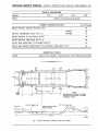
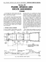
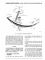
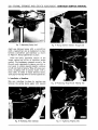
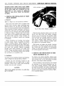
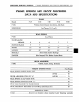
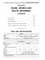
220—FRAME, SPRINGS AND SHOCK ABSORBERS CHRYSLER SERVICE MANUAL
Section IX
FRAME, SPRINGS AND
SHOCK ABSORBERS
CONTENTS
Page
Frame Alignment
223
Spring Maintenance
224
Rear Spring Interliners
225
Removal and Installation of Front Shock Absorbers
228
Removal and Installation of Rear Shock Absorbers
228
DATA AND SPECIFICATIONS
FRAME
Models
TYPE
DIMENSIONS
C-71
C-72
|
C-73
|
C-70
Welded, Double-Channel Box Section, Side Rails
See Figures 1, 2, 3 and 4
REAR SPRINGS
TYPE
NO. OF LEAVES
SEDANS
TOWN & COUNTRY WAGON
*5
7
6
7
7
7
WIDTH
2.5
2.5
2.5
2.5
LENGTH
55"
55"
55"
55"
SHACKLE
Semi-Elliptic
Silent Block Rubber Bushings
HANGER
Side Strapped with Rubber Bushed Bolts
*SIX LEAF SPRINGS USED ON ALL CARS EQUIPPED WITH AIR CONDITIONING UNITS,
OR POWER PACKAGE.
CHRYSLER SERVICE MANUAL FRAME, SPRINGS AND SHOCK ABSORBERS—221
SHOCK ABSORBERS
Modelsi
C-71
C-72
C-73
C-70
Oriflow, Double Acting, Hydraulic
TYPE
TORQUE SPECIFICATIONS
Foot-Pounds
REAR SPRING SILENT BLOCK NUT
60
UPPER
LOWER
SHOCK ABSORBER STUD NUT y2"
60
70
REAR SPRING U-CLIP BOLT NUTS
70
REAR SPRING SHACKLE NUTS Ke"
50
SWAY BAR BRACKET TO FRAME BOLTS
55
SWAY BAR SHAFT RETAINER TO CONTROL ARM BOLT NUT
55
ESSENTIAL TOOLS
Remover and Installer—Shock Absorber Lower Mounting Assembly
C-3413
NOTE
GAUGE
HOLE
DIMENSIONS ARE SHOWN AS INCHES
AND ARE PLUS OR MINUS V\6 UNLESS
OTHERWISE NOTED
TOP OF FRAME LINE
TOP OF FRAME LINE
GAUGE HOLE IN EACH
SIDE OF FRAME
A
55x37B
Fig.
1—Frame
Dimensions (Windsor and New Yorker)
222—FRAME, SPRINGS AND SHOCK ABSORBERS CHRYSLER SERVICE MANUAL
Section IX
FRAME, SPRINGS AND
SHOCK ABSORBERS
FRAME
A full length box section frame with redesigned crossmembers and longer side rails are
used on 1956 Chrysler Models.
1. CHECKING FRAME ALIGNMENT
mensional limits. It is possible that ordinary
straightening methods will suffice for minor
damage. In case of serious damage or fracture,
however, the entire front suspension crossmember, brace and support must be replaced. Before member is replaced, it is essential that
frame alignment be checked and corrected if
necessary. Whenever possible, parts should be
securely fastened with hot rivets. In cases
where no riveting equipment is available, finished bolts snugly fitted in reamed holes may
be used. The nuts should be securely tightened
and non-spreading lockwashers used. (Cold rivets are not recommended unless adequate power
press equipment is available to do a secure riveting job.)
In case of collision, frame members can often
be satisfactorily straightened to required di-
When welding frame members, care must be
taken to localize the heat so that the steel hard-
The convertible coupe frames have X-members as formerly, to reduce body shake and improve frame to body attachment. A rear axle
control strut and center bearing propeller shaft
has been incorporated in frame and rear axle
housing design of C-73 Model for the purpose
of controlling rise of nose of rear axle carrier
under varying load conditions (See Paragraph
8, Universal Joints, Section XII, for adjustment procedures).
48%6
NOTE
DIMENSIONS ARE S H O W N AS INCHES
AND ARE PLUS OR MINUS K6 UNLESS
OTHERWISE NOTED
TOP OF FRAME LINE
TOP OF FRAME LINE
GAUGE HOLE IN EACH
SIDE OF FRAME
55x38B
Fig. 2—Frame
Dimensions (Custom
Imperial)
CHRYSLER SERVICE MANUAL FRAME, SPRINGS AND SHOCK ABSORBERS—223
NOTE
76
DIMENSIONS ARE SHOWN AS INCHES
AND ARE PLUS OR MINUS K6 UNLESS
OTHERWISE NOTED
TOP OF FRAME LINE
TOP OF FRAME LINE
GAUGE HOLE IN EACH
SIDE OF FRAME
55x39B
Fig.
3—Frame Dimensions (Crown Imperial)
ness of frame will be retained. Reinforcement
welds should run lengthwise, along side of reinforcement.
Figures 1, 2, 3 and 4 show various dimensions
to be used as a guide for checking frame alignment. These dimensions are the true distance
between two points as measured with a steel
tape.
Figure 4 shows a few of various measurements that may be taken to check "squareness"
of frame. Diagonal measure will quickly deter-
mine which section of frame is bent and where
force should be applied to restore correct alignment.
2. FRAME ALIGNMENT
To properly check a frame for alignment, diagonal measurement should be performed with
great care. When body is removed, the frame
may be easily checked for alignment by measuring diagonals, as shown in Figure 4, with
trammels or steel tape and check dimensions
given in Figure 1, 2 and 3. Measurements may
55x40
Fig. 4—Typical Frame Diagonal Measurements
224—FRAME, SPRINGS AND SHOCK ABSORBERS CHRYSLER SERVICE MANUAL
be taken without removing body from chassis
by using a plumb-bob and chalk line on level
floor.
Attach line of plumb-bob to center of one of
rear body bolts. The plumb-bob should be suspended slightly above floor. When plumb-bob
comes to rest, mark floor directly underneath it.
The marks made on floor will represent various points of frame to be checked diagonally.
Move car away so the distance can be measured
to compare with the diagonal measurements,
shown in Figures 1, 2, 3 and 4.
3. REPLACING BODY SUPPORT BRACKETS
The body support brackets are welded to frame
in manufacturing. Due to "Box" construction
of frame, rivets cannots be used to attach a
new body bracket to frame.
Cut damaged bracket off frame, file surface
smooth. Clamp new bracket in correct position
and weld securely to frame member.
The shielded arc-weld method is recommended
for frame welding, or replacement of body
frame support brackets. The heat generated
from welding operation is localized and burning of material is held to a minimum when a
mild steel welding rod is used.
Install body bolt and washers, insulator and
nut. Tighten to 18 foot-pounds torque. On Convertibles, install a solid spacer, bolt and nut,
and tighten securely.
SPRINGS
The rear springs used on Chrysler cars are of
the semi-elliptical design. The front ends of rear
springs are mounted to removable hangers
which are bolted to brackets welded to outer
surface of frame side rails. (See Fig. 5).
The spring front pivot bolts are cushioned
in rubber which tends to help reduce noise and
allows increased riding comfort through a reduction in torque and brake reaction shock. (No
lubrication is required at this point.)
The rear ends of springs are attached to
frame through medium of flat plate shackles,
rubber shackle bushings, shackle bolts and
nuts. (See Fig. 6.) Thus, suspension of rear
springs in rubber, tends to reduce road noise
to a minimum. (No lubrication is required at
the rear shackles.)
hold spring hanger to frame bracket. The pivot
bolts cannot be removed unless this is done.
4. SPRING MAINTENANCE
It is important that spring "U" bolts be inspected at regular intervals and kept tight to
prevent spring breakage. Tighten spring "U"
bolt nuts to 70 foot-pounds torque. The spring
shackles should be inspected occasionally to
make sure they are tight, but not binding.
Tighten to 50 foot-pounds torque. No lubrication of any kind must be used on rubber bushings.
The width of spring leaves are 2i/£ inches
(refer to Data and Specifications.) Thus, with
outboard-mounted rear springs, rear-end roll is
greatly reduced and car stability on curves or
sharp turns is maintained.
NOTE
Cars equipped with air conditioning units are
equipped with a heavier rear spring.
Should it become necessary to install new
springs or silent blocks, it will be necessary to
remove four bolts, nuts and lockwashers that
56 K 232
Fig. 5—Rear Spring Front Mounting
CHRYSLER SERVICE MANUAL FRAME, SPRINGS AND SHOCK ABSORBERS—225
NUT
PLATE
DASHER
'-BOLT
RETAINER
BUSHING,
WASHER
BOLT
BUMPER
NUT-
WASHER
SILENT BLOCK
NUT
1
BOLT
SHACKLE
WASHER
54x544A
Fig. 6—Typical Rear Spring Suspension (Exploded View)
Front spring heights may be affected if rear
spring height varies more than % inch on one
side as compared with other side. To check
this, measure vertical distance from top of rear
spring main leaf to underside of frame side
rail on both sides of car. If these distances differ by more than % inch, this is an indication
that one of rear springs should be replaced.
This condition could be due to a bent frame
kick-up or an incorrectly welded spring saddle.
CAUTION
Care should be taken when replacing rear spring
on Imperial Models to see that the rear axle
housing to strut shims are reinstalled in same
position so as to maintain correct propeller
shaft to axle pinion shaft angle.
5. REPLACEMENT OF REAR SPRING
INTERLINERS
The 1956 Chrysler rear springs are similar to
those previously used with exception of rear
spring interliners. To replace interliners, proceed as follows:
a. Removal
Unload rear springs by jacking up the rear end
of frame until rear shock absorbers are fully
extended.
Remove alignment clips from springs. If any
of removed parts (nut, bolt, spacer, clip) are
damaged, use corresponding replacement parts.
Examine spring interliners. If any are missing, or if any have lost their metal fasteners,
they must be replaced. For replacement of
these interliners, proceed as outlined below.
Pry out metal fastener directly beneath
spring leaf surface and slip out old interliner,
after separating the spring leaf to which interliner was fastened from the next longer spring
leaf. To effect this separation, pry open the
226—FRAME, SPRINGS AND SHOCK ABSORBERS CHRYSLER SERVICE MANUAL
Fig. 7—Separating Spring Leaf
Fig. 9—Prying Interliner Fastener Through Leaf
slight gap between leaves with a screwdriver
until a tapered bar can be hammered in place
between screwdriver and interliner as shown
in Figure 7. Keep tapered bar in place.
Clean the lower (grooved) surface of the
longer spring leaf as far as interliner makes
contact. Use sandpaper wrapped around a flat
file and scrub vigorously to remove any dirt or
rust spots to obtain smooth metallic surfaces
to left and right of groove. Wipe off excess particles, including dirt in groove itself, with a
clean cloth. In order to reach between leaves,
open gap by bearing down on end of tapered bar.
b. Installation of Interliner
Slip new interliner in place by opening gap
between the spring leaves again with tapered
Fig. 10—Positioning Wrap-Around Aligning Clip
Fig. 8—Positioning New Interliners
Fig. 11—Tightening Aligning Clip
CHRYSLER SERVICE MANUAL FRAME, SPRINGS AND SHOCK ABSORBERS—227
bar and moving interliner until prongs of metal
fasteners are aligned with holes in the shorter
leaf, as shown in Figure 8.
With tapered bar still in place, pry prong
end of each metal fastener through hole in
spring leaf, as shown in Figure 9.
out, reversing operation which was used to insert bar in position. A faster method for withdrawing bar is to insert end of a bar with a
short tapered hook alongside the tapered bar.
After tapered bar has been withdrawn, the bar
with hook can be slipped out easily using leverage motion inward on the far end of hooked bar.
Remove tapered bar which has remained between leaves during these operations. The bar
may be withdrawn while a screwdriver is placed
alongside. Then the screwdriver may be pulled
Position wrap-around alignment clip and
tighten retainer nut, as shown in Figures 10
and 11. Peen end of bolt over nut so it will
not loosen.
SHOCK ABSORBER
Chrysler cars are equipped with double acting Oriflow shock absorbers. Oriflow shock absorbers provide a smoother, steadier ride with
greater comfort and stability, which is particularly noticeable at high speeds or on rolling or
rough roads. In the Oriflow shock absorber,
resistance is built up slowly at beginning of
stroke so as not to jolt passengers. This resistance is increased to a maximum at mid stroke
and is tapered off to zero at end of movement.
The major part of dampening is accomplished
at high velocity mid-operation of stroke where
no jolt can originate. There can be little jolt
at beginning and at end of stroke because both
velocities of movement and resistance offered
by the shock absorber are low at those points.
This simply means that the piston encounters
minimum resistance at beginning of stroke and
is gradually slowed down by increased resistance due to fluid velocity through the orifices.
In turn, slow movement of piston causes fluid
velocity to decrease and offer minimum resistance at termination of stroke.
absorber piston speed. Then drive over a fairly
smooth road to test resistance during slower
shock absorber piston speeds.
Hand testing Oriflow shock absorbers will
only reveal complete failure. The amount of ride
control evident from a hand test on bench is
small, compared with control exerted under
actual riding conditions. For this reason, it is
impossible to feel any sudden resistance in an
Oriflow shock absorber, no matter how fast it
is operated by hand.
7. SERVICING THE ORIFLOW SHOCK
ABSORBER
The Oriflow shock absorber cannot be refilled
or disassembled. Where servicing is required,
the shock must be removed and a new unit installed. SHOCK ABSORBERS SHOULD ONLY
UPPER
MOUNTING
6. TESTING ORIFLOW SHOCK ABSORBERS
Oriflow shock absorbers are designed to operate
with low resistance when operated slowly and
with high resistance when operated rapidly.
Since they operate with little resistance when
compressed by hand or by bench test methods,
their true operating efficiency can be determined
best by a road test. It is impossible to determine
operating efficiency of Oriflow shock absorbers
by rocking the car by the bumper.
When road testing, drive car over a fairly
rough road to test resistance under fast shock
LOWER MOUNTING
ASSEMBLY
SCREW
•LOCK WASHER
55P1014
Fig. 12—Front Shock Absorber Installed
228—FRAME, SPRINGS AND SHOCK ABSORBERS CHRYSLER SERVICE MANUAL
BE REPLACED IF THEY HAVE LOST THEIR
RESISTANCE IN ONE OR BOTH DIRECTIONS
OR IF THEY DRIP OIL. EVIDENCE OF OIL
MOISTURE IS NOT CAUSE TO REPLACE
THEM AS SEAL MUST WEEP TO PREVENT
SCORING.
SHOCK ABSORBER ASSEMBLY
8. REMOVAL AND INSTALLATION OF FRONT
SHOCK ABSORBER
a. Removal
Refer to Figure 12 and proceed as follows:
Raise hood and remove dirt or grease from
around shock absorber upper mounting area.
Remove piston rod nut and cup washer. Remove two lower mounting bolts, then withdraw
shock absorber through opening in bottom of
spring seat. The lower cup washer may remain
in place or drop through when shock absorber
is removed. Using a suitable drift, force inner
steel sleeve out of bushing, then remove bushing from frame opening. Check bushing for
deterioration or fatigue. Install new bushing
if necessary.
Before installing new bushing, dip bushing
in soapy water, insert in position in frame,
using a twisting motion. When properly installed, groove in bushing will index with frame.
Force steel sleeve through opening in bushing
and down into position. Remove mounting
bracket from shock absorber eye using Tool
C-3413. Press mounting bracket and bushing
out of eye. The mounting bracket and bushing
are serviced as an assembly only.
b. Installation
To install a new mounting bracket and bushing,
refer to Figure 12 and proceed as follows:
Position the new mounting bracket so the
mounting holes are at a right angle to shock
absorber. Using Tool C-3413, press mounting
bracket into eye until centered.
CAUTION
Always press against steel sleeve to avoid damage to assembly.
Fig. 13—Rear Shock Absorber Installed
Extend shock absorber piston rod to its full
travel, and slide lower cup washer (concave
side up) over rod and down into position. Slide
shock absorber up through opening in spring
seat (be sure the extended piston rod enters
steel sleeve through upper bushing), and up
into position. Install retaining bracket bolts
and tighten 35 foot-pounds torque.
Slide piston rod upper cup washer (concave
side down) over piston rod and down on bushing. Install nut, and tighten 35 foot-pounds
torque, or until upper and lower concave washers bottom against steel sleeve.
9. REMOVAL AND INSTALLATION OF REAR
SHOCK ABSORBERS (Fig. 13)
To remove rear shock absorber, remove nuts
from shock absorber mounting stud pins which
pass through eyes at top and bottom of shock
absorber, and remove shock absorber.
When installing a shock absorber, first install
the bushings in the shock absorber's eye. Install inner bushing retainers, shock absorber
and bushing assembly and outer retainers and
nut. The concave face of each retainer must fit
against convex face of adjacent bushing. Tighten to specified torque.