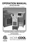
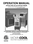
1
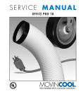
SERVICE MANUAL CLASSIC 10 SERIAL NUMBER FROM FEBRUARY 2011 (0211) TO PRESENT DocID: 00G00089E © 2012 DENSO SALES CALIFORNIA, INC. All rights reserved. This book may not be reproduced or copied, in whole or in part, without the written permission of the publisher. DENSO SALES CALIFORNIA, INC. reserves the right to make changes without prior notice. MovinCool®, Office Pro® and SpotCool® are registered trademarks of DENSO Corporation. Table of Contents Table of Contents Operation Section 1. PRECAUTIONS FOR SAFETY 1.1 Foreword . . . . . . . . . . . . . . . . . . . . . . . . . . . . . . . . . . . . . . . . . . . . . . . . . . . . . . . . . . . . . . . . . . . . . . . 5 1.2 Definition of Terms . . . . . . . . . . . . . . . . . . . . . . . . . . . . . . . . . . . . . . . . . . . . . . . . . . . . . . . . . . . . . . . 5 1.3 General Precautions. . . . . . . . . . . . . . . . . . . . . . . . . . . . . . . . . . . . . . . . . . . . . . . . . . . . . . . . . . . . . 5 2. SPECIFICATIONS 2.1 Exterior Dimension Diagram. . . . . . . . . . . . . . . . . . . . . . . . . . . . . . . . . . . . . . . . . . . . . . . . . . . . . . . . 6 2.2 Technical Specifications . . . . . . . . . . . . . . . . . . . . . . . . . . . . . . . . . . . . . . . . . . . . . . . . . . . . . . . . . . . 7 2.3 Characteristics . . . . . . . . . . . . . . . . . . . . . . . . . . . . . . . . . . . . . . . . . . . . . . . . . . . . . . . . . . . . . . . . . . 8 3. CONSTRUCTION 3.1 Internal Structure . . . . . . . . . . . . . . . . . . . . . . . . . . . . . . . . . . . . . . . . . . . . . . . . . . . . . . . . . . . . . . . 10 4. REFRIGERATION SYSTEM 4.1 Refrigeration System Construction . . . . . . . . . . . . . . . . . . . . . . . . . . . . . . . . . . . . . . . . . . . . . .. . . . . 11 4.2 Compressor . . . . . . . . . . . . . . . . . . . . . . . . . . . . . . . . . . . . . . . . . . . . . . . . . . . . . . . . . . . . . . . . . . . 12 4.3 Condenser . . . . . . . . . . . . . . . . . . . . . . . . . . . . . . . . . . . . . . . . . . . . . . . . . . . . . . . . . . . . . . . . . . . . 15 4.4 Capillary Tube. . . . . . . . . . . . . . . . . . . . . . . . . . . . . . . . . . . . . . . . . . . . . . . . . . . . . . . . . . . . . . . . . . 15 4.5 Evaporator . . . . . . . . . . . . . . . . . . . . . . . . . . . . . . . . . . . . . . . . . . . . . . . . . . . . . . . . . . . . . . . . . . . . 16 4.6 Accumulator . . . . . . . . . . . . . . . . . . . . . . . . . . . . . . . . . . . . . . . . . . . . . . . . . . . . . . . . . . . . . . . . . . . 16 4.7 High Pressure Switch . . . . . . . . . . . . . . . . . . . . . . . . . . . . . . . . . . . . . . . . . . . . . . . . . . . . . . . . . . . . 16 5. ELECTRICAL SYSTEM 5.1 Circuit Diagram . . . . . . . . . . . . . . . . . . . . . . . . . . . . . . . . . . . . . . . . . . . . . . . . . . . . . . . . . . . . . . . . . 17 5.2 Control Box . . . . . . . . . . . . . . . . . . . . . . . . . . .. . . . . . . . . . . . . . . . . . . . . . . . . . . . . . . . . . . . . . . . . 19 5.3 Control Specifications. . . . . . . . . . . . . . . . . . . . . . . . . . . . . . . . . . . . . . . . . . . . . . . . . . . . . . . . . . . . 24 5.4 Compressor. . . . . . . . . . . . . . . . . . . . . . . . . . . . . . . . . . . . . . . . . . . . . . . . . . . . . . . . . . . . . . . . . . . . 27 5.5 Fan Motor . . . . . . . . . . . . . . . . . . . . . . . . . . . . . . . . . . . . . . . . . . . . . . . . . . . . . . . . . . . . . . . . . . . . . 28 5.6 Temperature Thermistor. . . . . . . . . . . . . . . . . . . . . . . . . . . . . . . . . . . . . . . . . . . . . . . . . . . . . . . . . . 29 5.7 Drain Tank Switch. . . . . . . . . . . . . . . . . . . . . . . . . . . . . . . . . . . . . . . . . . . . . . . . . . . . . . . . . . . . . . . 30 6. CONNECTION AND SETTING 6.1 Warning Signal Connection . . . . . . . . . . . . . . . . . . . . . . . . . . . . . . . . . . . . . . . . . . . . . . . . . . . . . . . 31 6.2 Fire Alarm Control Panel Connection . . . . . . . . . . . . . . . . . . . . . . . . . . . . . . . . . . . . . . . . . . . . . . . 32 7. OPERATION 7.1 Operation of Control Panel . . . . . . . . . . . . . . . . . . . . . . . . . . . . . . . . . . . . . . . . . . . . . . . . . . . . . . . 33 3 4 Table of Contents Repair Section 8. TROUBLESHOOTING 8.1 Troubleshooting . . . . . . . . . . . . . . . . . . . . . . . . . . . . . . . . . . . . . . . . . . . . . . . . . . . . . . . . . . . . . . . . 35 8.2 Self-Diagnostic Codes. . . . . . . . . . . . . . . . . . . . . . . . . . . . . . . . . . . . . . . . . . . . . . . . . . . . . . . . . . . . 35 8.3 Troubleshooting Chart . . . . . . . . . . . . . . . . . . . . . . . . . . . . . . . . . . . . . . . . . . . . . . . . . . . . . . . . . . . 37 8.4 Basic Inspection . . . . . . . . . . . . . . . . . . . . . . . . . . . . . . . . . . . . . . . . . . . . . . . . . . . . . . . . . . . . . . . . 42 8.5 Compressor Inspection . . . . . . . . . . . . . . . . . . . . . . . . . . . . . . . . . . . . . . . . . . . . . . . . . . . . . . . . . . 43 8.6 Fan Motor Inspection . . . . . . . . . . . . . . . . . . . . . . . . . . . . . . . . . . . . . . . . . . . . . . . . . . . . . . . . . . . 43 8.7 Capacitor Inspection ( For Fan Motor and Compressor ). . . . . . . . . . . . . . . . . . . . . . . . . . . . . . . . . 44 8.8 Full Drain Switch Inspection . . . . . . . . . . . . . . . . . . . . . . . . . . . . . . . . . . . . . . . . . . . . . . . . . . . . . . . 45 8.9 Thermistor Inspection . . . . . . . . . . . . . . . . . . . . . . . . . . . . . . . . . . . . . . . . . . . . . . . . . . . . . . . . . . . . 45 8.10 Wiring Connection Inspection . . . . . . . . . . . . . . . . . . . . . . . . . . . . . . . . . . . . . . . . . . . . . . . . . . . . . . 45 8.11 Refrigeration System Inspection . . . . . . . . . . . . . . . . . . . . . . . . . . . . . . . . . . . . . . . . . . . . . . . . . . . . 46 9. DISASSEMBLY 9.1 Parts Construction . . . . . . . . . . . . . . . . . . . . . . . . . . . . . . . . . . . . . . . . . . . . . . . . . . . . . . . . . . . . . . 47 9.2 Disassembly . . . . . . . . . . . . . . . . . . . . . . . . . . . . . . . . . . . . . . . . . . . . . . . . . . . . . . . . . . . . . . . . . . . 48 9.3 Fan Motor Removal. . . . . . . . . . . . . . . . . . . . . . . . . . . . . . . . . . . . . . . . . . . . . . . . . . . . . . . . . . . . . . 51 9.4 Removal of Electrical Components . . . . . . . . . . . . . . . . . . . . . . . . . . . . . . . . . . . . . . . . . . . . . . . . . 56 9.5 Full Drain Switch Removal . . . . . . . . . . . . . . . . . . . . . . . . . . . . . . . . . . . . . . . . . . . . . . . . . . . . . . . . 60 10. REFRIGERATION SYSTEM REPAIR 10.1 Repair of Refrigeration System. . . . . . . . . . . . . . . . . . . . . . . . . . . . . . . . . . . . . . . . . . . . . . . . . . . . . 61 10.2 Removal of Refrigeration System Components . . . . . . . . . . . . . . . . . . . . . . . . . . . . . . . . . . . . . . . . 63 10.3 Charging the System with R-410A Refrigerant. . . . . . . . . . . . . . . . . . . . . . . . . . . . . . . . . . . . . . . . . 65 10.4 Refrigerant Charging Work . . . . . . . . . . . . . . . . . . . . . . . . . . . . . . . . . . . . . . . . . . . . . . . . . . . . . . . . 69 11. REASSEMBLY 11.1 Reassembly of the Unit . . . . . . . . . . . . . . . . . . . . . . . . . . . . . . . . . . . . . . . . . . . . . . . . . . . . . . . . . . . 71 11.2 Compressor Installation . . . . . . . . . . . . . . . . . . . . . . . . . . . . . . . . . . . . . . . . . . . . . . . . . . . . . . . . . . . 71 11.3 Fan Assembly. . . . . . . . . . . . . . . . . . . . . . . . . . . . . . . . . . . . . . . . . . . . . . . . . . . . . . . . . . . . . . . . . . 72 11.4 Wiring Information . . . . . . . . . . . . . . . . . . . . . . . . . . . . . . . . . . . . . . . . . . . . . . . . . . . . . . . . . . . . . . . 72 Operation Section 1. PRECAUTIONS FOR SAFETY 1.1 Foreword • This manual has been published to service the MovinCool Classic 10. Please use this service manual only when servicing this unit. 1.2 Definition of Terms WARNING CAUTION NOTE Describes precautions that should be observed in order to prevent injury to the user during installation or unit operation. Describes precautions that should be observed in order to prevent damage to the unit or its components, which may occur during installation or unit operation if sufficient care is not taken. Provides additional information that facilitates installation or unit operation. 1.3 General Precautions WARNING • All electrical work should only be performed by qualified electrical personnel. Repair to electrical components by non-certified technicians may result in personal injury and/or damage to the unit. All electrical components replaced must be genuine MovinCool parts, purchased from an authorized reseller. • When handling refrigerant, always wear proper eye protection and do not allow the refrigerant to come in contact with your skin. • Do not expose refrigerant to an open flame. • The power supply for this unit should be a dedicated single outlet circuit with a UL recognized short-circuit and ground-fault protective breaker to prevent electrical shock from the unit. • When brazing any tubing, always wear eye protection, and work only in a well ventilated area. 5 6 Operation Section 2. SPECIFICATIONS 2.1 Exterior Dimension Diagram 6-M6 8 3. 1 A. A. 4. 9 DI DI 5.5 .8 4.0 11.5 41.5 19.5 6.5 13 13.0 16.5 19.3 (Unit: inch) 3.1 20.7 1.8 25.6 ILL00548-00 Operation Section 2.2 Technical Specifications ITEM Operation Voltage Requirement Operating Voltage Max. Range Min. Starting Current Recommended Fuse Size FLA LRA Cooling Capacity and Power Consumption Evaporator: 95 °F (35 °C), 60 %RH Total Cooling Capacity Condenser: 95 °F (35 °C), 60 %RH Sensible Cooling Capacity Power Consumption Current Consumption EER Power Factor Type Compressor Output Type of Evaporator Evaporator Type of Fan Air Flow Max. External Static Pressure Motor Output*1 Type of Condenser Condenser Type of Fan Air Flow Max. External Static Pressure Motor Output*1 Refrigerant Control Refrigerant Type Amount Fire Alarm Input (Signal Type) Signal Connection Electronic Features Electrical Characteristics Power Cord Dimension Weight Drain Tank Capacity Operating Condition Range Warning Signal Output NEMA Plug Configuration Gauge x Length W×D×H Net Shipping Max. Inlet Air Min. Temperature Cold Duct Maximum Duct Length Hot Duct 2 With Condenser Duct Sound Level* Without Condenser Duct Compressor Overload Protector Safety Devices Fan Motor Overload Protector Freeze Protection Thermistor Full Drain Tank Switch Automatic Restart (Power Interruption) Compressor Time Delay High Pressure Interruption*3 Signal Input/Output Temperature Control Control Devices • Specifications are subject to change e without notice. < NOTE > *1: One motor rotates both the evaporator and the condenser fans. *2: Measured at 3 feet (1.0 m) from surface of the unit. *3: For unit serial number from November 2011 (1111) to Present. SPECIFICATIONS Digital Programmable Single-Phase, 115 V, 60 Hz 127 V 104 V 43 A 15 A 9.7 A 43 A 10000 Btu/h (2940 W) 4500 Btu/h (1320 W ) 1.05 kW 9.7 A 9.5 94 % Hermetic Rotary 0.70 kW Plate Fin Centrifugal Fan 265 CFM (451 m3/h) 0.33 IW G (82 Pa) 0.15 kW Plate Fin Centrifugal Fan 740 CFM (1258 m3/h) 0.13 IW G (32 Pa) Capillary Tube R-410A 1.43 lb (0.65 kg) •No-voltage contact input • Contact resistance less than 100 ohm 2 A at 30 V (DC/AC) or less (resistive load) 5-15 14 AWG (3-core) × 10 ft (3.0 m) 19.4 × 26.5 × 41.5 in (493 × 673 × 1054 mm) 156 lb (71 kg) 194 lb (88 kg) 5.0 gal (19 L) 104 °F (40 °C), 50 %RH 70 °F (21 °C), 50 %RH 40 ft (12.2 m) 60 ft (18.3 m) 55 dB (A) 58 dB (A) Included Included Included Included Included 120 sec Included Included Included 7 Operation Section 2.3 Characteristics Dry Bulb Temp. °F (°C) Cooling Capacity. x103 Btu/h (1) Cooling capacity curve at 115 V 13.9 11.9 9.9 7.9 6.0 104 (40) 95 (35) 86 (30) 77 (25) 59 (15) 68 (20) 77 (25) 86 (30) Wet Bulb Temp. °F (°C) ILL00563-00 (2) Power consumption curve at 115 V Power Consumption. kW 1.2 Dry Bulb Temp. °F (°C) 8 1.1 1.0 0.9 0.8 104 (40) 95 (35) 86 (30) 77 (25) 68 (20) 77 (25) 86 (30) 95 (35) Wet Bulb Temp. °F (°C) ILL00564-00 Operation Section (3) Cool air temperature difference curve Temperature Difference Between Inlet and Outlet (Delta-T) °F (°C) at 115 V 27.0 (15) 25.2 (14) 23.4 (13) 21.6 (12) 19.8 (11) 18.0 (10) 16.2 (9) 14.4 (8) 12.6 (7) 40 50 60 70 Relative Humidity. % ILL00565-00 9 10 Operation Section 3. CONSTRUCTION 3.1 Internal Structure Control Panel Room Thermistor (RTS) Condenser Air Outlet Cooling Air Duct Housing for Condenser Fan Housing for Evaporator Fan Condenser Fan and Motor Evaporator Freeze Protection Thermistor (CTS) Condenser Capillary Tube Compressor and Accumulator Drain Tank High Pressure Switch Control Box • Relay Board • Capacitor Locking Swivel Caster (Front) Full Drain Switch Caster (Rear) ILL00549-00 Operation Section 11 4. REFRIGERATION SYSTEM 4.1 Refrigeration System Construction The component parts of the refrigeration system include the following: • Compressor, Evaporator, Condenser, Accumulator, Capillary tube, High Pressure Switch. The parts above are all connected by copper piping with brazed connections. Evaporator Condenser Evaporator Outlet Pipe Capillary Tube Evaporator inlet Pipe Condenser Inlet Pipe Connecting Pipe (Evaporator to Compressor) Connecting Pipe (Condenser to Capillary Tube) Compressor Discharge Pipe Compressor Suction Pipe Condenser Outlet Pipe High Pressure Switch Compressor Accumulator Condenser Flow of Refrigerant Accumulator Capillary Tube Fan Motor Evaporator Compressor ILL00550-00 12 Operation Section 4.2 Compressor • The compressor used for the unit is hermetically sealed. The compressor and the compressor motor are in one casing. (1) Compressor construction • The construction of a rotary type compressor is divided into two mechanisms; the drive mechanism (compressor motor), and the compression mechanism (compressor). When the rotor shaft of the motor (drive mechanism) turns, the roller (compression mechanism) rotates to compress the refrigerant. To Condenser From Evaporator Accumulator Terminal Strainer Stator Rotor Cylinder Roller Lubricator Blade Discharge Valve Oil I001675 Operation Section (2) Basic compressor operation • The roller (compression mechanism) is set eccentrically with a certain distance given from the axis of the center of the cylinder. A spring Discharge Hole Discharge Valve loaded blade is mounted on the cylinder. The Spring Suction Hole Blade roller turns to compress the refrigerant in the space between the cylinder and eccentrically mounted roller. The blade is in contact with the Shaft Roller roller by means of spring force. The blade Cylinder I000510 partitions the space between the suction side and the discharge side to keep compressed refrigerant from returning to the suction side. There is no suction valve. The discharge valve is designed not to open until the pressure of the refrigerant within the cylinder reaches or exceeds discharge side pressure. As a result, the discharge valve prevents the backward flow of refrigerant gas. 13 14 Operation Section (3) Operation 1) Start of compression Discharge Valve 1) The cylinder is filled with low pressure gas. Blade 2) Since pressure in the discharge chamber is higher than in the cylinder, the discharge valve is kept closed. Roller I001676 2) Suction and compression Discharge Valve 1) The pressure in the cylinder increases gradually. Blade 2) Refrigerant suction begins on the suction side of the cylinder. 3) The discharge valve remains closed. Roller I001677 3) Discharge Discharge Valve 1) The pressure in the cylinder exceeds that in the discharge chamber, and the discharge Blade valve opens. 2) On the suction side, refrigerant suction continues. Roller I001678 4) Completion of compression 1) When compression is completed, all of the Discharge Valve refrigerant has been drawn from the suction Blade chamber. 2) Operation then returns to step 1) (Start of compression) and the above process of suction Roller I001679 and compression repeatedly in succession. continues Operation Section (4) Compressor lubrication • The lubrication system is comprised of a hollow shaft, an oil scraper mounted at the end Rotor face, hollow shaft, a shaft journal (shaft bearing), and the lubrication groove for the shaft journal. The lubrication groove is wider than the oil hole. When the shaft turns, oil is Hollow Shaft Eccentric Shaft Cylinder Roller scraped upward by the oil scraper along the inside diameter of the hollow shaft. The oil is fed through the oil hole by centrifugal force, then supplied to the lubrication groove for each shaft journal, lubricating the bearing. In this lubrication system, oil enters into each bearing Oil Feed Groove Oil Hole Oil Scrapper separately and returns to the oil reservoir. I001680 This system effectively prevents bearing temperature increases, and offers high reliability. In addition, the specially treated shaft journal keeps the bearing from being damaged during high temperature operation. 4.3 Condenser • The condenser is a heat exchanger with copper tubes that are covered with thin aluminum projections called plate fins. • Heat is given off and absorbed by air being pulled across the condenser fins by the centrifugal fan and then expelled through the exhaust air duct. 4.4 Capillary Tube • The capillary tube is a long thin tube that ILL00551-00 High Temp./High Pressure Liquid Refrigerant utilizes line flow resistance as an expansion valve. The length and the inner diameter of the capillary tube are determined according to the capacity of the refrigeration system, operating conditions, and the amount of refrigerant. The high pressure, high temperature liquid Low Temp./Low Pressure Gas and Liquid Mixture I001887 refrigerant sent from the condenser expands rapidly as the refrigerant is sprayed out through the fixed orifice in the capillary tube. As a result, the temperature and state of the refrigerant becomes low and mist-like, and therefore evaporates easily. 15 16 Operation Section 4.5 Evaporator • The evaporator is a heat exchanger covered with plate fins. Heat is removed from the air being pulled across the evaporator by the centrifugal fan. The resulting cool air is expelled through the cooling air ducts. ILL00552-00 4.6 Accumulator • The accumulator is mounted on the suction From Evaporator gas piping between the evaporator and the compressor. The accumulator separates the liquid refrigerant from the gas refrigerant, allowing only the gas refrigerant to enter the compressor. In the accumulator, suction gas is led into a cylindrical vessel where the speed of the gas is decreased. This process separates To Compressor I000514 the refrigerant contained in the gas by the force of gravity, causing the refrigerant to accumulate at the bottom of the vessel. As a result, the compressor is protected from possible damage caused by liquid refrigerant intake. 4.7 High-Pressure Switch • The high-pressure condenser and switch compressor prevents from the Pressure of Refrigerant being damaged by excessive high pressure in the Snap Disk Movable Point high-pressure line of the refrigeration cycle. The switch is normally closed. The snap disk responds to the variations in pressure and, if Stationary Point Case pressure is abnormally high, the snap disk moves down to push the pin down, causing the Molding by Resin internal contacts to open. This interrupts the ground signal at the relay board which turns the compressor off. Pin Terminal Lead Wires I001768 17 Operation Section 5. ELECTRICAL SYSTEM 5.1 Circuit Diagram For Unit Serial Number from February 2011 (0211) to October 2011(1011) Dip Switch R ON OFF (Default) MF MC 1 2 3 IOLF 4 G S C G #1 : ON: Fan Stop Mode (Fan Auto) OFF: Fan Operate Mode (Fan On) #2 : N/A #3 : N/A #4 : ON: The Buzzer Sound Disabled 1 2 CF TB2 L- OLC CC Output Signal 1 2 1 2 L+ EE+ On Board Controller Fine Alarm Input CN9 11 CN23 CN25 1 5 1 5 520D2 1 1 CN21 3 CN22 CN24 2 1 1 COM 52CT 520D1 52ID F1 Dip Switch Ground (G) RB 115V T T R AP R TB1 ON 11 CN17 1 1 5 CB 1 1 1 2 3 4 CN13 5 AC115V 1PHASE 60Hz 5 CN01 CN12 3 1 CN11 3 1 2 CN16 1 CN15 52CM 3 1 2 4 G 3 CN8 Control Box CN Jumper Line CTS TB1 TB2 RB MF MC CF CC OLC Terminal Block1 Terminal Block2 Relay Board Fan Motor Compressor Motor Capacitor for Fan Motor Capacitor for Compressor Overload Protector RTS CN CTS RTS G CB HPRS Drain Tank SW HPRS Connector for Option Drain Pump Freeze Protection Thermistor Room Thermistor Ground Control Board High Pressure Switch ILL00553-00 18 Operation Section For Unit Serial Number from November 2011 (1111) to Present Dip Switch ON R OFF (Default) 1 2 3 MF MC 4 IOLF G S C #1 : ON: Fan Stop Mode (Fan Auto) OFF: Fan Operate Mode (Fan On) #2 : N/A #3 : N/A #4 : ON: The Buzzer Sound Disabled TB2 L- G OLC 1 2 CF CC Output Signal 1 L+ 2 1 2 EE+ On Board Controller CN9 11 Fine Alarm Input CN23 CN25 1 1 5 520D2 1 1 CN22 520D1 3 1 CN21 1 CB 5 1 2 3 CN8 1 COM 115V 3 T T R R AC115V 1PHASE 60Hz CN12 1 3 CN11 1 2 CN16 1 CN15 3 1 5 52CM CN03 4 3 G CN-HP HPRS 2 Control Box CN-PUMP CTS TB1 TB2 RB MF MC CF CC OLC AP TB1 4 1 5 CN17 CN13 1 RB 1 5 CN01 ON 11 2 52CT F1 52ID Dip Switch 1 Ground (G) CN24 5 Terminal Block1 Terminal Block2 Relay Board Fan Motor Compressor Motor Capacitor for Fan Motor Capacitor for Compressor Overload Protector RTS Drain Tank SW CN-PUMP CTS RTS G CB HPRS Jumper Line Connector for Option Drain Pump Freeze Protection Thermistor Room Thermistor Ground Control Board High Pressure Switch ILL00554-00 Operation Section 5.2 Control Box For Unit Serial Number from February 2011 (0211) to October 2011 (1011) TB2 : Terminal Block2 E+ EL+ L- RB:Relay Board TB1:Terminal Block 1 CF:Capacitor for Fan Motor CC:Capacitor for Compressor ILL00559-00 For Unit Serial Number from November 2011 (1111) to Present TB2 : Terminal Block2 E+ EL+ L- CF:Capacitor for Fan Motor RB:Relay Board TB1:Terminal Block 1 CC:Capacitor for Compressor ILL00555-00 19 20 Operation Section (1) Capacitor • The capacitor is used to improve the rotational power of the fan motor and compressor at startup. The specification for each capacitor is shown below. ILL00561-00 Model Capacitor Rated Voltage Capacitance For unit serial number from February 2011 (0211) to March 2011 (0311) For Fan Motor 450 V 16 μF For Compressor 450 V 55 μF For unit serial number from April 2011 (0411) to Present For Fan Motor 250 V 25 μF For Compressor 450 V 55 μF Operation Section 21 (2) Relay board • The relay board contains the dip switch, the compressor and fan relays, and a step-down transformer that reduces the line voltage from 115VAC to approx. 14 VAC. This voltage is then rectified from 14 VAC to 12 VDC and used for relay coil activation. The 12 VDC voltage is sent to the control panel assembly, and further being reduced to 5 V for the system logic. CN23 CN22 CN21 CN24 Relay Board Fuse (5A) CN01 CN25 CN17 CN13 CN12 CN11 CN04 CN03 CN02 CN14 CN16 CN15 4-Position Dip Switch “OFF” Position ILL00556-00 1) Power supply requirements • This unit requires a single-phase 115 V, 60 Hz power supply. 2) Relay board fuse • The relay board fuse is the only serviceable component on the relay board assembly. This fuse provides protection against damage to the step-down transformer. The fuse must be replaced with the exact same part, or a suitable equivalent. Specifications: - 5 A, 250 VAC CAUTION Failure to use the exact same fuse may result in damage to the unit and/or components, and will also void the unit warranty. 22 Operation Section 3) Input signal • The relay board receives inputs from the control panel, sensors, and external devices to perform device control. Control Panel Input Symbol Indication SW1 ON/OFF Button SW2 FAN Button Function On/off control for unit operation. Turns the unit on and off. Changes the fan control mode between continuous and automatic on/off control. SET TEMP SW3 Connector CN17 Increases the set temperature. Button SET TEMP SW4 Decreases the set temperature. Button Sensor Input Specification Symbol Type Connector Characteristic RTS Room Thermistor Freeze Protection CTS Thermistor “Short” Detection “Open” Detection 5 k ohm at 77 °F 181 °F (83 °C) or -29 °F (-34 °C) or (25 °C) more less 5 k ohm at 77 °F 181 °F (83 °C) or -29 °F (-34 °C) or (25 °C) more less CN11 CN12 External Input Signal Specification Symbol Signal Fire AUX2 TANK FULL S/W mA at DC12 V Input (Off: No signal) Tank Full Switch (Contact: Normally open) LED shows “AL”, Output signal “ON” Off: Activates “Defect control” (Contact: Normally closed) (Off: No signal) CN15 On board buzzer sound LED shows “FL”, Output signal “ON” On: Between 10 to 20 Connector On: Activates “Defect control” mA at DC12 V Failure Switch Function (Off: No signal) mA at DC12 V Pressure HPRS On: Between 10 to 20 Pump High *1 On: Between 10 to 20 Alarm External AUX1 Specification CN16 Off: 1) From 1 to 180 seconds - Compressor stops. 2) After 180 seconds - Compressor stops. CN13 LED shows “AS”, Output signal turns “ON” On: Between 0.4 to 1.0 Off: Activates “Defect control” (Contact: Normally closed) mA at DC 5V (Off: No signal) 1) Activates 3 times in 24 hours: LED shows blinking “HP”. 2) Activates 10 times in 24 hours: LED shows “HP”, Output signal “ON” *1 : For unit serial number from November 2011 (1111) to Present CN03 Operation Section 4) Dip switch setting • The controller is equipped with a four position dip switch that defaults in the OFF position. The dip switch can be set to configure the following functions: ON 1 2 3 4 Symbol DSW4 Item Buzzer Function On --- Disable “onboard buzzer” Off --- Enable “onboard buzzer” DSW3 - N/A DSW2 - N/A DSW1 Fan Mode Change Fan Mode On --- Fan stop mode (Fan AUTO) Off --- Fan operate mode (Fan ON) I002623 23 24 Operation Section 5.3 Control Specifications (1) Fan control • When the FAN button is pressed, the 52ID (fan motor on/off) relay on the relay board turns on, operating the fan. Specifications: - 52ID (Fan motor On-Off) relay contact rating: 5 A at 250 VAC (2) Compressor start control • When the ON/OFF button is pressed, the 52CM relay on the relay board turns on, operating the compressor. Specifications: - 52CM (Compressor On-Off) relay contact rating: 20 A at 250 VAC (3) Anti-freeze control • Anti-freeze controls turns the compressor on and off by turning the 52CM relay on in accordance with the freeze protection thermistor (CTS) temperature. As a result, decreases in cooling performance due to frost buildup on the evaporator are prevented. • Compressor off conditions: Freeze protection thermistor (CTS) temperature 29 °F (-1.5 °C) • Compressor on (recovery) conditions: CTS temperature 59 °F (15 °C) ON 52CM OFF 29 °F (-1.5 °C) 59 °F (15 °C) CTS temperature (Evaporator out temperature) I001687 Operation Section (4) Compressor time delay control (compressor protection) • Compressor protection consists of a time delay program within the microprocessor. This program prevents a heavy load from being applied to the compressor motor when restarting the unit (cool mode) after a very short period of time. This “delay” is in effect any time the compressor is turned on by either the COOL ON/OFF button, or power interruption restart (automatic recovery.) Specifications: - Time Delay: 120 seconds. 1st Time (After initial set up, reset circuit breaker, etc.) Compressor turns off and on immediately (within 120 sec.) [Example] Turn ON Compressor turns off and on more than 120 sec. later ON Controller OFF Status Compressor ON Status OFF (52CM) No Delay Time (less than 5 sec.) Delay Time (120 sec.) No Delay Time (Less than 5 sec.) Stop (for Extended Period) Delay Time (120 sec. after last turn off) Reference: Initial turn on Within: 120 sec. after (the power cord is connected to) the power supply, the compressor will start with delay timer. After: 120 sec. since (the power cord was connected to) the power supply, the compressor will start without delay timer. I001688 (5) Automatic restart and recovery function • The microprocessor contains a feature that automatically restart the unit after power is lost and regained, and also has memory to store and recover operation status in the event of a power loss. Status of memory during power interruption • When the input power is off, the status items below are saved in the memory. - Running status (on or off) - Operating mode: Cool mode or fan only mode - Set temperature - Temperature mode (°F or °C) - Fan mode: Fan operation mode (fan on) or fan stop mode (fan auto) 25 26 Operation Section (6) Temperature control • During cool mode, temperature control changes the 52CM (compressor on/off) relay status according to RTS temperature in the available range (-4 °F to 140 °F (-20 °C to 60 °C)). ON 52CM (Compressor Relay) OFF (Set Temp. -3 °F) (Set Temp. -1.7 °C) Set Temp Inlet Air Temperature When compressor operation continues within this range for more than 5 minutes, the 52CM relay stops. I002624 (7) Fire alarm signal control • When receiving the signal from the fire alarm control panel, the buzzer sounds, and the 52CT (signal output) relay on the relay board turns on. Operation Section 5.4 Compressor (1) Compressor motor • The compressor motor is a single-phase motor and is contained within the same housing as the compressor. Specifications: Rated Voltage 115 V Rated Output 700 W I002355 (2) Compressor overload relay • An external compressor overload relay is used Bimetal to protect the compressor motor. This relay is mounted within the connector housing that attaches to the top of the compressor. The Points relay interrupts the flow of current when there is an overload condition such as high current Terminal draw and/or high temperature build up in the compressor. I001691 Operating Temperature Non-Operating Limit at 212 °F OFF (Open Contacts) ON (Closed Contacts) (100 °C) 302 °F (150 °C) 142 °F (61 °C) 12.8 A Marking MRA1261-12026 27 28 Operation Section 5.5 Fan Motor (1) For unit serial number from February 2011 (0211) to March 2011 (0311) • The fan motor is a single phase, induction type. The motor rotates the fan on both the evaporator side and the condenser side at the same time. Specifications: Rated Voltage 115 V Rated Output 140 W I001692 (2) For unit serial number from April 2011 (0411) to Present • The fan motor is a single phase, induction type. The motor rotates the fan on both the evaporator side and the condenser side at the same time. Specifications: Rated Voltage 115 V Rated Output 150 W ILL00560-00 < NOTE > An internal overload relay is used to protect the fan motor. This relay is built into the fan motor and interrupts the flow of current when there is an over current situation, or if there is an abnormally high temperature build up in the fan motor. Operation Section 5.6 Temperature Thermistor • The room thermistor (RTS) is installed upstream of the evaporator, and detects evaporator inlet temperature as a resistance value. • The freeze protection thermistor (CTS) is installed in the evaporator outlet piping, and detects low temperature on the evaporator as a resistance value. I001695 Specification Type Characteristic Room Thermistor (RTS) Freeze Protection Thermistor (CTS) “Short” Detection “Open” Detection 5 k ohm at 77 °F (25 °C) 181 °F (83 °C) or more -29 °F (-34 °C) or less 5 k ohm at 77 °F (25 °C) 181 °F (83 °C) or more -29 °F (-34 °C) or less 29 30 Operation Section 5.7 Drain Tank Switch • The drain switch activates and stops the operation of compressor motor and fan motor when approximately 4.4 gal (16 L) of drain water accumulates in the drain tank. At the same time, control panel display "FL", and compressor and fan operations stop. This system uses a 250 V, 0.1 A rating micro switch for this function. • When approximately 4.4 gal (16 L) of drain water accumulates in the drain tank, the drain tank base plate, which is supported at fulcrum (a), is pushed down in the direction of the arrow. • When the drain tank base plate is forced down, “portion A”, located at the top of the drain tank base plate, turns off micro switch contacts (1)-(2). Evaporator Portion “A” Drain Pan Full Drain Switch NC (2) Relay Board (CN16) 2 1 NC NO 3 COM Drain Tube C (1) Drain Tank Drain Water Spring a Base Base Plate ILL00593-00 Operation Section 31 6. CONNECTION AND SETTING 6.1 Warning Signal Connection (Output Signal Terminal L+ and L-) • The controller is equipped with a warning signal output relay type (Form C, normal open dry contact) which can be used to monitor the failure conditions. Relay contactor is closed if any of the following conditions has occurred: - Tank Full - Temperature sensor fails - High pressure switch errorr *1 < NOTE > * 1 : For unit serial number from November 2011 (1111) to Present • The relay output contactor is rated 2 A at 30 VDC or 2 A at 30 VAC (resistive load) and it is compatible with various warning devices such as alarm speaker, light indicators, etc. Connecting warning signal from controller 1 ) Remove service panel from the rear of the unit. 2 ) Squeeze the inner latches and push out the black cap from inside the panel. (See drawing of cap and inner latch shapes.) 3 ) Insert the warning signal wire through the hole in the rear panel. Use recommended warning signal wire size from 16 AWG to 26 AWG or a solid wire, or 16 AWG to 22 AWG for a stranded wire with ring terminal for #6 stud size. 4 ) Connect warning device to terminal L+ and L- according to its polarities. <Cap> Unit Terminal Warning Device E+ EL+ L- Latch Relay Output Contactor ILL00078-00 Input Signal ILL00079-00 32 Operation Section 6.2 Fire Alarm Control Panel Connection (Input Signal Terminal E+ and E-) • The controller is equipped with a normal open input signal, which can be connected directly from the fire alarm control panel. When receiving the signal from the fire alarm control panel, the unit turns off and does not turn back on until it has been reset. Connecting fire alarm control panel to controller 1 ) Remove service panel from the rear of the unit. 2 ) Squeeze the inner latches and push out the black cap from inside the panel. (See drawing of Cap and inner latch shapes.) 3 ) Insert the fire alarm signal wire through the hole in the rear panel. Use recommended warning signal wire size from 16 AWG to 26 AWG for a solid wire, or 16 AWG to 22 AWG for a stranded wire with ring terminal for #6 stud size. 4 ) Connect warning device to terminal E+ and E- according to its polarities. <Cap> Unit Terminal Fire Alarm Device Output Signal E+ EL+ L- Latch Open Dry Contact ILL00080-00 ILL00078-00 Operation Section 33 7. OPERATION 7.1 Operation of Control Panel (1) Control panel •Before operating the unit, it is important to be familiar with the basic operation of the control panel. 5 6 1 2 4 7 3 1 COOL ON/OFF Button Activates/deactivates the cool mode; turns the unit off. 2 FAN Button Activates/deactivates the fan only mode; turns the unit off. 3 SET TEMP Buttons ( / ) Increases/decreases the temperature set point during cool mode. 4 Room Temperature/ Set Point Display Shows a blinking set point temperature for 5 seconds, then continuously indicates room temperature. 5 Temperature Scale LED Illuminates to indicate the current temperature being displayed is either in °C or °F. 6 ON LED Illuminates during fan only mode and cool mode using fan operate mode. 7 AUTO LED Illuminates during cool mode using fan stop mode. [LED Display Indication] In normal operation, LED displays the following indication. Display Indication Conditions Right decimal segment is on Power stand by or during fan only mode Indicates room temperature when display is solid. (Left fig. : Room temp. at 78 °F) During cool mode Indicates set point temperature when display is flashing. (Left fig. : Set Point temp. at 75 °F) During set point temperature adjustment or cool mode on. (5 seconds) ILL00557-00 < NOTE > • The room temperature display range is from 0 °F to 109 °F. (When displayed in “°C ” the range is from -9 °C to 60 °C) • In Fahrenheit only, when the display value is greater than 99 °F, 100 °F, 101 °F, and 109 °F are displayed as “00”, “01”, and “09” respectively. 34 Operation Section (2) Fan only mode • When the FAN button on the control panel is pressed, the FAN “ON” LED illuminates, and the fan operates. At this time, the compressor is off, and only the fan is in operation. When the FAN button is pressed again, the fan stops. (3) Cool mode • When the COOL ON/OFF button is pressed, the FAN “ON” LED illuminates, and room temperature is shown on the display. At this time, the compressor and fan begin to operate to provide cooling. When the COOL ON/OFF button is pressed again, the compressor and fan stop. • When the COOL ON/OFF button is pressed in fan only mode, room temperature is shown on the display, and the compressor operates to provide cooling. If room temperature reaches the set temperature during cooling operations, the compressor stops, and only the fan continues to operate. (Fan operate mode is a default setting from the manufacturer.) < NOTE > The fan only mode will not operate after the cool mode has been activated. Once the cool mode is activated, the unit cannot be turned off by pressing the fan button. Rather, the COOL ON/OFF button must be pressed. *Fan stop mode - In fan stop mode, if room temperature reaches the set temperature during cooling operations, both the compressor and fan stop. The fan stop mode setting can be changed using the dip switch on the relay board. (For details, refer to page 23). During cooling operations when in the fan stop mode, the FAN “AUTO” LED illuminates. (4) Change temperature mode “°C” and “°F” • The temperature display can be switched between “°C” and “°F” by holding the SET TEMP arrow buttons ( , ) and the FAN button down simultaneously for 3 seconds. (5) Diagnostic code • Most of the diagnostic codes can be RESET by holding the SET TEMP arrow buttons ( , ) down simultaneously for 3 seconds. (For details, refer to page 35 to 36.) 35 Repair Section 8. TROUBLESHOOTING 8.1 Troubleshooting • Before troubleshooting the system, the following inspection should be performed. WARNING Disconnect power supply from the unit before performing any service. Beware that some residual voltage may remain in the unit immediately after the power is disconnected. (1) Inspection Voltage of the Power Source • Check the voltage of the power source. - Single Phase 115V ( 60 Hz) • Check the operation and condition of the fuse or circuit breaker in the power source. (2) Inspection of Air Filters • Remove the air filters and check the element, if the element is dirty, wash the element as described in the OPERATION MANUAL supplied with the unit. 8.2 Self-Diagnostic Codes • Self-diagnostic codes are displayed on the control board under the following conditions. Indication Condition Output Signal Buzzer (On Board) Yes Yes Yes No When the fire alarm control panel input signal is CLOSED, the unit turns off, the LED displays “AL”, and the buzzer turns on. This condition returns to normal when the input No. 1 signal is once again OPEN, and unit has been RESET. To RESET, hold down the SET TEMP buttons ( / ) simultaneously for 3 seconds, and the controller returns to normal status. When the drain tank switch is activated, the LED displays “FL” and the unit turns off automatically. Once emptying the drain tank procedure is No. 2 completed and ON/OFF has been pushed, unit returns to normal operation. 36 Repair Section Indication Condition Output Signal Buzzer (On Board) No No Yes No Yes No Yes No Yes No Yes No When the high pressure switch (connected to CN03) is activated (= CN03 input turns open) for the first 2 times in 24 hours, “HP” turns on but goes away as the high pressure switch resets. No. 3*1 If the high pressure switch is activated 3 times in 24 hours, “HP” blinks and signal output (CN24) turns on. When the high pressure switch is activated 10 times in 24 hours, “HP” turns on and signal output (CN24) turns on. To RESET, hold down the SET TEMP buttons ( / ) simultaneously for 3 seconds, and the controller returns to normal status. Improper hose connection (including kink or blockage) or a defect in the condensate pump for more than 180 seconds will display "AS" on the LED resulting the compressor to stop immediately; however, fan will continue to operate. No. 4 Normal condition is resumed when condensate pump or hose connection is fixed, and the unit has been RESET. To RESET, hold down the SET TEMP buttons ( / ) simultaneously for 3 seconds, and the controller returns to normal status. When room thermistor becomes open or shorted, display shows “E1” and cool mode No. 5 operation is off. Display and cool mode operation are returned to normal operation after condition is corrected. When freeze protection thermistor becomes open or shorted, display shows “E2” and cool No. 6 mode operation is off. Display and cool mode operation are returned to normal operation after condition is corrected. *1 : For unit serial number from November 2011 (1111) to Present Repair Section 8.3 Troubleshooting Chart • To accurately troubleshoot the problem, it is important to carefully confirm the nature of the problem. Common problems are: - Insufficient cooling. - Unit does not operate. - Overflow of drain water. - Abnormal noise or vibrations. - Others. (1) Insufficient cooling • This problem may occur from electrical components, mechanical components, environmental condition, or installation location. Refer to the troubleshooting chart on the next page for possible causes of insufficient cooling and remedies. 37 38 Repair Section Possible Cause Condition Insufficient Cooling Remedy Check Area 1. Usage conditions Cause Operation near usage limits. (high temperature). 2. Dirt in condenser or Compressor operates. Air volume place. Insufficient heat exchange. Clean fins. evaporator. 3. Frost in refrigeration cycle. Clogging at the frost section. Replace clogged section. 4. No temperature difference Insufficient refrigerant. Check the leaking part, between evaporator and then repair and charge condenser. refrigerant. 1. Compressor coil resistance. (0 ohm or ohm normal Review the installation Short or open circuit. Replace compressor. (In case of short, check the compressor relay on the relay board) Compressor does not operate. 2. Compressor on/off relay (52CM) on the relay board. Open circuit or insufficient contact. Replace relay board. 3. Capacitor for compressor and fan motor. 4. Compressor overload relay. Capacitor malfunction. Replace capacitor. Overload relay fault. Replace overload relay. 5. Voltage. Low voltage. Repair power supply. Defective high pressure switch ( short or open ). Loose high pressure switch connection. Short or open circuit. Replace high pressure switch. Reconnect high pressure switch and check connection. Replace fan motor. Open circuit or bad contact . Replace relay board. 1. Air filter. Clogged air filter. Clean air filter. 2. Evaporator. Clogged evaporator or Repair and clean fins, or crushed fins. replace evaporator. 3. Duct connection state. Improper connection. Repair duct connection. 4. Fan motor. Insufficient rotation. Replace motor. 6. High Pressure Switch*1. 1. Coil resistance of fan motor. (0 ohm or ohm) No air. 2. Fan motor on-off relay (52ID) on the relay board. Insufficient air volume Insufficient air volume. *1 : For unit serial number from November 2011 (1111) to Present. Repair Section (2) Unit does not start (operate) • This problem occurs mainly from the safety devices, electrical components, environmental condition, or installation location. Refer to the troubleshooting chart below and the next page for possible causes of unit does not start and remedies. Possible Cause Condition Remedy Check Area Unit does not operate. Unit does not operate Cause 1. Voltage. Power failure. 2. Ground fault breaker trip. Ground fault or defective Repair ground fault ground fault breaker. section. Control panel LED display 3. LCDI power cord trip. turns off. Repair power supply. Reset or repair breaker. Leakage current detected. Reset power cord. Replace power cord. 4. Fuse. 1. Display code “FL”. Fuse blown on relay board. Check and fix shorted circuit and replace fuse. Drain tank is filled with the Discharge the drain water. RESET the controller*1. drain water. 2. Display code “AS” Control panel Control panel LED display display shows turns off. error codes. Loose drain switch connection. Reconnect the drain switch and check the connection. RESET the controller*1. Defective Drain Switch. Replace the drain switch. RESET the controller*1. Optional condensate pump stops pumping water due to any kinks/blockage in the drain line or due to improper routing of the drain line. Remove any blockage or kinks from the drain line or improve hose installation. RESET the controller*1. Defective condensate pump. Replace the condensate pump. RESET the controller*1. Missing jumper connector at the pump connector. Insert the pump connector and check the connection. RESET the controller*1. 3. Display code “AL” with beep sound. Signal is input from the fire alarm. Check the fire alarm system and confirm there is no input signal to the unit, then RESET the controller*1. 4. Display code “E1”. Loose or defective room thermistor. Reconnect or replace room thermistor. RESET the controller*1. 5. Display code “E2”. Loose or defective freeze protection thermistor. Reconnect or replace freeze protection thermistor. RESET the controller*1. *1 : To RESET the controller, press SET TEMP ( / ) buttons simultaneously for 3 seconds. 39 40 Repair Section Possible Cause Condition Unit does not operate. Remedy Check Area *2 Cause Operating outside of the operating temperature’s range. Check environmental condition. Do not use the unit outside the operating range (See page 7). RESET the controller*1. Loose high-pressure switch connection. Reconnect the high pressure switch and check the connection. Defective high-pressure switch (short/open). Replace high pressure switch. Refrigerant is over charged. Charge the correct amount of refrigerant (See page 70). RESET the controller*1. Open circuit or insufficient contact. Replace relay board. Insulation failure on fan motor. Replace fan motor. Insulation failure on compressor. Replace compressor. 1. Coil resistance of fan motor. Defective fan motor. Replace fan motor. 2.Temperature of fan motor abnormally high. Operation of safety device (IOLF) due to fan motor malfunction. Operation of safety device (IOLC) due to compressor malfunction. Insufficient refrigerant or gas leakage. Replace fan motor. Insufficient cooling of condenser. Clean air filter and condenser. 6.Display code “HP” . Control panel Control panel LED display display shows turns on. error codes. 1.Fan Motor on/off relay (52ID) on the relay board. Unit stops Control panel 2. Fan Motor insulation immediately LED displays resistance. after starting normal. 3.Compressor insulation resistance. Unit stops Control panel 3.Temperature of compressor after running LED displays abnormally high. for a while. normal. 4. Dirt on air filter or condenser. *1 : To RESET the controller, press SET TEMP ( / ) buttons simultaneously for 3 seconds. *2 : For unit serial number from November 2011 (1111) to Present. Replace compressor. Repair and charge refrigerant. Repair Section 41 (3) Drain water overflow Possible Cause Condition Remedy Check Area Cause 1. Drain pan. Cracks in drain pan. Check and replace. 2. Water level in drain pan. Clogged drain hose. Check and repair. 3. Drain hole. Reversed air flow from drain Insert a trap on the hole. discharge drain hose. Reversed air flow from drain Clean air filter. Overflow from the unit. 4. Clogged air filter. hole due to the excessive negative pressure inside of the unit. (4) Abnormal noise or vibration • To prevent abnormal noise or vibration, carefully determine the source of the problem and come up with proper countermeasures to solve the problem so that it does not occur again. Possible Cause Condition Remedy Check Area 1. Fan. Abnormal noise or vibration. Cause Fan interference. Repair interfering section. Fan deformation. Replace fan. 2. Compressor fixing nuts. Loose nuts. Tighten nuts further. 3. Piping. Pipe interference. Repair interfering section. 4. Panel fixing screws. Loose screws. Tighten screws further. 42 Repair Section 8.4 Basic Inspection • Perform the following inspections before disassembly. (1) Inspection of plate fins • To inspect the plate fins of either the evaporator or condenser, the air filter must be removed. After removal of the air filters, inspect the plate fins for any dirt, dust, lint, or debris that may have caused insufficient cooling performance of the unit. If cleaning of the fins is necessary, it is recommended that this service be performed by a qualified service I001780 technician. (2) Examination of operating environment • Operating environments can vary depending on location, climate and surrounding conditions. Installation location can also cause operational problems. Consult with your reseller concerning operational environment requirements. (3) Cooling capacity inspection • Measure the temperature difference between the evaporator inlet and the cooling air duct Cooling Air Duct Thermometer outlet. If the difference is out of the range shown in the graphs on page 9, proceed with the remedy suggested in the troubleshooting chart on page 35 to 41. Inlet of Evaporator ILL00597-00 Repair Section 8.5 Compressor Inspection (1) Compressor motor inspection • Measure resistance across the terminals of the C S compressor motor. Resistance at 77 °F (25 °C) R-C C-S Approx. 0.83 ohm Approx. 1.92 ohm R ILL00603-00 • If the measured resistance is not equal to the standard values listed above, replace the compressor. The compressor has an external overload relay. The overload relay should be operational if the above resistance is obtained under normal temperature. For overload relay specifications, refer to the chart below. (2) Overload relay inspection • Check for continuity across two terminals of the overload relay. At normal temperature, there should be continuity across the terminals. Operating Temperature OFF (open contacts) ON (closed contacts) 302 °F (150 °C) 142 °F (61 °C) • If there is no continuity across the terminals, I001701 replace the overload relay. 8.6 Fan Motor Inspection (1) For unit serial number from February 2011 (0211) to March 2011 (0311) • Measure resistance across the terminals of the fan motor. Resistance at 68 °F (20 °C) CF1-TBT CF2-TBT TBT Approx. 7.06 ohm Approx. 8.73 ohm CF2 • If the measured resistance is not equal to the standard values listed above, replace the fan motor. CF1 I001702 43 44 Repair Section (2) For unit serial number from April 2011 (0411) to Present • Measure resistance across the terminals of the fan motor. Resistance at 68 °F (20 °C) CF1 - CN21-3 CF2 - CN21-3 Approx. 8.2 ohm Approx. 9.8 ohm CN21 • If the measured resistance is not equal to the CF2 CF1 standard values listed above, replace the fan ILL00562-00 motor. 8.7 Capacitor Inspection (For Fan Motor and Compressor) (1) Ohmmeter method • Set the ohmmeter to the 10 M ohm range. Place the two probes against the two terminals of the capacitor. At first, the ohmmeter indicates small value, then the reading should gradually increase towards infinity (), indicating that the capacitor is charging. If the reading indicates infinity immediately (open), ILL00567-00 or the ohmmeter fails to move from 0 ohm (shorted), replace the capacitor. (2) Capacitance tester method • Use a capacitance tester to check the capacitors for the values indicated below. If the value tested is not within 10% of the indicated capacitance, replace the capacitor. Unit Serial Number Capacitor Rated Voltage Capacitance From February 2011 (0211) to March 2011 (0311) For Fan Motor 450 V 10 μF For Compressor 450 V 55 μF From April 2011 (0411) to Present For Fan Motor 250 V 25 μF For Compressor 450 V 55 μF WARNING • Properly discharge the capacitor(s) before and after testing. Failure to discharge the capacitor may cause damage to the test equipment and/or unit, and result in personal injury (electrical shock) or death. 45 Repair Section 8.8 Full Drain Switch Inspection • Depress the full drain switch to check for continuity. If there is no continuity, replace the Full Drain Switch switch. NC (2) • Normally: Continuity across 1 and 2. • Switch Depressed: Continuity across 1 and 3. Relay Board (CN16) 2 NC 1 NO 3 COM C (1) I001745 8.9 Thermistor Inspection • Use an ohmmeter to check the resistance across the 2-pin connector at normal temperature (77 °F (25 °C)). Specification Type Characteristic Room Thermistor (RTS) Freeze Protection Thermistor (CTS) 5 k ohm at 77 °F (25 °C) 5 k ohm at 77 °F (25 °C) I001695 8.10 Wiring Connection Inspection • Refer to the wiring diagram on page 17 to 18, and check the connection of each wire. CAUTION Secure the wires using clamps to prevent contact with the edges of the structure, etc. Secure the wires in the same position as prior to removal. 46 Repair Section 8.11 Refrigeration System Inspection • In most cases, the causes for insufficient cooling is a clog in the system, a leakage, or an incorrect amount of refrigerant. In such cases, inspect the system according to the following procedure. (1) Clogged refrigeration system • Check the component parts of the refrigeration system, including piping, that could be clogged with refrigerant. If clogged with refrigerant, only the clogged part is partially frosted. If this occurs, change the part in question (see page 63). (2) Refrigerant leak • Carefully check all connections, and each component for leaks whenever the refrigeration system is installed or repaired. Use an electronic gas leak tester to inspect the system. (See page 68). (3) Insufficient refrigerant • When the unit is not producing sufficient cooling, follow the troubleshooting chart on page 38 to confirm the cause of the problem. Then, charge the system with the refrigerant to the specified amount as indicated on page 70. 47 Repair Section 9. DISASSEMBLY WARNING Disconnect power supply from the unit before performing any service. Beware that some residual voltage may remain in the unit immediately after the power is disconnected. 9.1 Parts Construction Room Thermistor Upper Panel Cooling Air Duct Control Panel Right Side Panel Front Panel Air Filter Housing for Condenser Fan Air Filter Housing for Evaporator Fan Condenser Fan and Motor Left Side Panel Rear Panel Drain Pan Drain Tank Full Drain Switch Service Panel Locking Swivel Caster Power Cord Caster ILL00604-00 48 Repair Section 9.2 Disassembly 1) Remove the drain tank. Cooling Air Duct 2) Unfasten the two clips and the lower-side hook, Screws (4) and then remove the front panel. 3) Take out the four (4) screws, and then remove the cooling air duct. Front Panel Drain Tank I002600 4) Take out the seven (7) screws, and then remove Service Panel the service panel. Screws (7) I002601 5) Remove the two (2) power supply lines from the TB1:Terminal Block 1 Power Supply Lines (2) Ground Wire ILL00568-00 terminal block 1, and remove the ground wire. Repair Section 49 6) Take out the thirteen (13) screws, and then remove the rear panel. Screws (13) Rear Panel I002602 Screws (2) Upper Panel Screws (4) 7) Take out the fourteen (14) screws, and then remove the upper panel. CAUTION The two screws (2*) used on the front side of Screws (4) the upper panel differ from the rest. Ensure that the correct screws are used when attaching the upper panel. Screws (2*) Upper Panel Screws (2) Housing for Condenser Fan I002603 8) Unfasten the connector on the room thermistor wiring harness. Clamp 9) Remove the wiring harness from the clamp. Room Thermistor Harness Connector I001730 50 Repair Section 10) Unfasten the two connectors (11-pin, 5-pin) from Connectors Upper Panel Board Clamp the control panel. 11) Remove the wiring harness from the clamp and Control Panel board clamp. Clamp I001731 12) Take out the seven (7) screws, and then remove the left-side panel. Left Side Panel CAUTION The screw (1*) on the front side of the left-side panel differs from the rest. Ensure that the Screws (6) Screw (1*) correct screw is used when attaching the left-side panel. I002604 13) Remove the air filter from the right-side panel. Air Filter I001733 Screw (1) 14) Take out the eleven (11) screws, and then remove the right-side panel. Screw (1*) CAUTION The screw (1*) on the front side of the rightside panel differs from the rest. Ensure that the Screws (9) correct screw is used when attaching the Right Side Panel I002358 right-side panel. Repair Section 9.3 Fan Motor Removal (1) For Unit Serial Number From February 2011 (0211) to March 2011 (0311) Housing for Evaporator Fan Condenser Fan Evaporator Fan Partition Plate Fan Motor Motor Bracket Ring Housing for Condenser Fan ILL00576-00 51 52 Repair Section Condenser Fan 1) Loosen the set screw with a hex key, and then remove the condenser fan. CAUTION • Set Screw Torque Value (for Installation) - 10.80 ± 2.17 ft•lbf (14.7 ± 3.0 N•m) Set Screw I002361 2) Take off the thee (3) nuts, and then remove the Housing for Condenser Fan condenser fan housing. Nuts (3) ILL00573-00 3) Take off the four (4) nuts, and then remove the Nuts (4) fan motor together with the motor bracket. Motor Bracket Fan Motor ILL00574-00 4) Loosen the set screw with a hex key, and then remove the evaporator fan. Set Screw Evaporator Fan I001740 Repair Section 5) Take out the four (4) nuts, and then remove the fan motor. Nuts (4) Harness Clamp Fan Motor ILL00577-00 53 54 Repair Section (2) For Unit Serial Number From April 2011 (0411) to Present Housing for Evaporator Fan Condenser Fan Evaporator Fan Partition Plate Fan Motor Ring Motor Bracket Housing for Condenser Fan ILL00576-00 Repair Section Condenser Fan 55 1) Loosen the set screw with a hex key, and then remove the condenser fan. CAUTION • Set Screw Torque Value (for Installation) - 10.80 ± 2.17 ft•lbf (14.7 ± 3.0 N•m) Set Screw I002361 2) Take off the thee (3) nuts, and then remove the Housing for Condenser Fan condenser fan housing. Nuts (3) ILL00573-00 3) Take off the four (4) nuts, and then remove the Nuts (4) fan motor together with the motor bracket. Motor Bracket Fan Motor ILL00574-00 4) Loosen the set screw with a hex key, and then remove the evaporator fan. Set Screw Evaporator Fan I001740 56 Repair Section 5) Take out the four (4) bolts, and then remove the fan motor. Bolts (4) Fan Motor ILL00575-00 9.4 Removal of Electrical Components WARNING Disconnect power supply from the unit before performing any service. Beware that some residual voltage may remain in the unit immediately after the power is disconnected. (1) Removal of control panel 1) Take out the eight (8) screws, and then remove the control panel. Control Panel Screws (8) I002605 57 Repair Section (2) Removal of wire-harness in control box 1) Disconnect all the wires from the electrical parts in control box . For Unit Serial Number from February 2011 (0211) to October 2011 (1011) E- (Red) E+ (Red) TB2: Terminal Block 2 2-P (Brown) L+ (Brown) 2-P (Black) L- (Brown) 3-P (Black) 3-P (Red) E+ EL+ L- 2-P (Red) 3-P (Blue) 52CM4 (White) RB: Relay Board 5-P 52CM3 (White) 5-P 11-P CF1 (Black) 3-P (Black) TBR (White) CF1 (Black) TBT (Black) CF2 (Black) TBT (Black) TBR (White) TB1: Terminal Block 1 CF: Capacitor for Fan Motor G (Green) G (Green) G (Green) CC1 (White) CC1 (White) CC: Capacitor for Compressor CC2 (White) ILL00569-00 58 Repair Section 2) Disconnect all the wires from the electrical parts in control box. For Unit Serial Number from November 2011 (1111) to Present E- (Red) E+ (Red) TB2: Terminal Block 2 L+ (Brown) 2-P (Black) 2-P (Black) L- (Brown) 3-P (Black) 3-P (Red) E+ EL+ L- 2-P (Red) 3-P (Blue) 52CM4 (White) RB: Relay Board 5-P 2-P (Brown) 52CM3 (White) 5-P 11-P CF1 (Black) 3-P (Black) TBR (White) CF1 (Black) TBT (Black) CF2 (Black) TBT (Black) TBR (White) TB1: Terminal Block 1 CF: Capacitor for Fan Motor G (Green) G (Green) G (Green) CC1 (White) CC1 (White) CC: Capacitor for Compressor CC2 (White) ILL00594-00 59 Repair Section (3) Removal of control box 1) Take out the three (3) nuts, and then remove the control box. Control Box Nuts (3) I002606 (4) Removal of electrical parts - Terminal block 1 (power connection): Remove the two (2) screws from the control box. - Terminal block 2 (signal connection): Remove the two (2) screws from the control box. - Capacitor for compressor: Remove the one (1) screw from the control box. - Capacitor for fan motor: Remove the one (1) screw from the control box. - Relay Board: Remove the six (6) supports from the relay board. TB2: Terminal Block 2 Control Box Support RB: Relay Board TB1: Terminal Block 1 CF: Capacitor for Fan Motor CC: Capacitor for Compressor ILL00571-00 60 Repair Section 9.5 Full Drain Switch Removal 1) Take out the two (2) screws, and then remove the full drain switch cover. Screws (2) Full Drain Switch Cover I002609 2) Unfasten the wiring harness connector. Harness Connector 3) Take out the two (2) screws, and then remove the full drain switch. Full Drain Switch Screws (2) I002610 61 Repair Section 10. REFRIGERATION SYSTEM REPAIR 10.1 Repair of Refrigeration System • When there is a leak, obstruction, or problem in the refrigeration system of the unit, replace or repair the defective refrigeration component. After replacing any refrigeration component, all the connections must be brazed. (1) Proper brazing techniques • When brazing, use a slightly reduced flame. Oxyacetylene is commonly used since it is easy to verify and adjust the condition of the flame. Unlike gas welding, a secondary flame is used for brazing. It is necessary to preheat the base metal properly depending on the shape, size, or thermal conductivity of the brazed fitting. • The most important point in flame brazing is to bring the whole brazed fitting to a proper brazing temperature. Care should be taken to not cause overflow of the brazing filler metal, oxidation of the brazing filler metal, or to not deterioration due to overheating of the flux. (2) Brazed fittings and fitting clearance • In general, the strength of the brazing filler metal is lower than the base metal. Therefore, a the shape and clearance of brazed fitting Clearance 0.001~0.003 in (0.025~0.075 mm) brazed fitting, it is necessary to maximize its a are very important. As for the shape of adhesive area. The clearance of the brazed fitting must be minimized to facilitate brazing filler metal to flow into the fitting by capillary action. Clearance From The Pipe Fitting and Tubing. I002225 62 Repair Section (3) Cleaning brazing filler metal and pipe • When the refrigeration system has been opened and exposed to the heat which could cause the brazing filler metal to stick to the inside and outside of the pipe. Brazing filler metal may also be compounded with oxygen in the air to form the oxide film. In addition, grease and oils may stick to the pipe during handling. All these factors can reduce the effectiveness of brazing . It is necessary to eliminate the excessive brazing filler metal using sand paper and by thorough cleaning with solvent such as Trichlene. CAUTION • Do not use chlorine cleaner (4) Use of Dry Nitrogen gas • During brazing, the inside of the pipe undergoes an oxidative reaction due to the brazing flame. Introduce dry nitrogen gas (0.27 gal/min (1 L/min); adjust with the flow regulator) through the pinch-off tube of the refrigerant cycle to prevent oxidation. < NOTE > • Make sure not to allow dirt, water, oil, etc . to enter into the pipes. (5) Vertical joint • Heat the entire brazed fitting to a proper brazing temperature. Bring the brazing filler 45° metal into contact with the fitting so that the Vertical Down Joint Brazing Filler Metal Burner brazing filler metal starts to flow by itself. • Stop heating the fitting as soon as the brazing filler metal has flown into the gap (clearance). Since the brazing filler metal flows easily into the portions heated to a proper temperature, it Tube I000564 is essential to keep the whole fitting at a proper brazing temperature. Vertical Up Joint Tube Burner 45° Brazing Filler Metal I001725 Repair Section 10.2 Removal of Refrigeration System Components WARNING • Before replacing any refrigeration component, recover the refrigerant using standard recovery procedures and equipment. • When recovering the refrigerant, use the pinch-off tubes at the low pressure side (tube 1) and high pressure side (tube 2) as shown in figure below. CAUTION • To prevent oxidation, dry nitrogen should be conducted (flow rate 0.27 gal/min (1 L/min)) through the pinch-off tube during any brazing operation. • During any component replacement involving brazing, shield nearby parts with a steel plate to protect them from the flame. B Tube 1 D H F E A Tube 2 Pipe 2 Pipe 1 C G Part to Replace Disconnect at • Compressor (See the next page.) • Condenser A&C • Capillary Tube E&F • Evaporator D&F • High Pressure Switch G I ILL00579-00 63 64 Repair Section (1) Removal of compressor assembly TBT wire TB1:Terminal Block 1 Control Box CC1 wire CC2 wire CC:Capacitor for Compressor 1) Disconnect CC1 and CC2 wires (white) from the capacitor for compressor in the control box. Disconnect TBT wire (black) from the terminal block 1 in the control box. WARNING Disconnect power supply from the unit before performing any service. Beware that some residual voltage may remain in the unit immediate after the power is disconnected. ILL00600-00 Insulators 2) Remove the insulators from pipe 2 and accumulator. Pipe 2 Accumulator ILL00567-00 3) Braze at point A and B. A B Pipe 2 Pipe 1 ILL00598-00 4) Remove three (3) nuts and three (3) washers, and keep them for installation, then remove the compressor. Remove three (3) cushions and three (3) collars and discard. Nut (3) Washer (3) Cushion (3) Collar (3) Compressor ILL00599-00 65 Repair Section 10.3 Charging the System with R-410A Refrigerant • Always ensure that the refrigeration system has been properly evacuated before charging with the specified amount of R-410A. • Equipments is for R-410A only. • Liquid charge (no gas charge). • Make sure not to use more than 90 % of the initial weight of R-410A in the cylinder. WARNING • When handling refrigerant (R-410A), the following precautions should always be observed: - Always wear proper eye protection while handling refrigerant. - Maintain the temperature of the refrigerant container below 104 °F (40 °C). - Perform repairs in a properly ventilated area. (Never in an enclosed environment.) - Do not expose refrigerant to an open flame. - Never smoke while performing repairs, especially when handling refrigerant. - Take caution so that the liquid refrigerant does not come in contact with the skin. • If liquid refrigerant strikes eye or skin: - Do not rub the eye or the skin. - Splash large quantities of cool water on the eye or the skin. - Apply clean petroleum jelly to the skin. - Go immediately to a physician or to a hospital for professional treatment. Step 1 Connect manifold gauge. 1) Evacuate the system. • 15 minutes or more. Step 2 • 30 inHg (100 kPa) or more of vacuum. 2) Stop evacuating the system. • Leave for 5 minutes. When leak is found, repair the connection or components. 3) Check the vacuum. Step 3 Connect to refrigerant source. Step 4 Test the system for leaks. Step 5 Step 6 Charge the system with R-410A. • See “Technical Specifications” for the specified amount. Remove manifold gauge. ILL00084-00 66 Repair Section (1) Connection of gauge manifold 1) Properly remove the crushed end of the pinch-off Charging Hose Side Refrigerant Cycle Side tube at the high pressure side and the low pressure side of the refrigerant cycle with a pipe cutter. 2) Fit the process tube fitting to the pinch-off tube on both sides. Seal Pinch-Off Tube I002183 3) Connect the charging hoses (red high pressure Low Pressure Valve (Closed) High Pressure Valve (Closed) Red Hose Green Hose Process Tube Fitting High Pressure Side Tube side) for the gauge manifold to the process tube fitting. < NOTE > Connect the hoses using care not to mistake the high pressure side for the low pressure side and vice versa. Vacuum Pump (when stopped) I000568 4) Connect the charging hose (green) at the center of the gauge manifold to the vacuum pump. (2) Evacuation 1) Open the high pressure valve (Hl) of the gauge Valve Setting Gauge LO HI Closed Open LO HI Closed Closed 30 inHg (100 kPa) or larger Low Pressure Valve High Pressure Gauge High Pressure Valve High Pressure Side Tube Vacuum Pump (in Operation) manifold. 2) Turn on the vacuum pump to start evacuation. (Evacuate the system for approximately 15 minutes.) 3) When the high pressure gauge indicates 30 inHg (100 kPa) or higher, turn off the vacuum pump and close the high pressure valves of the gauge I002227 manifold. Repair Section 67 (3) Checking vacuum Valve Setting LO HI Closed Closed Pressure Gauge 1) Leave the high pressure valve and the low Leave valves closed for 5 minutes or more. Pointer of pressure gauge returning to zero indicates there is a leak. pressure valve of the gauge manifold closed for five minutes or more, and confirm that the gauge pointer does not return to zero. 2) If the gauge pointer returns gradually to zero, Return there is a leak somewhere in the system (this Pipe Brazing could also include gauge manifold). Perform a I003203 leak check according to the procedure indicated in the next step. Once the leak has been found and repaired, evacuate the system once more to confirm that the system holds vacuum. 68 Repair Section (4) Checking gas leak 1) Remove the charging hose (green) from the Valve Setting vacuum pump, and connect the hose to the LO HI Closed Closed Air Purging refrigerant cylinder (R-410A). Charging Hose Red (Green) To Process Tube Fitting 2) Loosen the nut on the gauge manifold side of the Refrigerant Cylinder R-410A Open The Valve of Refrigerant Cylinder charging hose (green). 3) Open the valve of the refrigerant cylinder and perform air purging in the charging hose (green). I001901 4) Open the high pressure valve of the gauge Valve Setting LO HI LO HI Closed Open Gauge Reading Closed Closed Refrigerant Cylinder Valve (Open) Refrigerant Cylinder R-410A Low Pressure Valve (Closed) Then tighten the nut. manifold. Charge the system with refrigerant until 57 psi (390 kPa) the high pressure gauge indicates 57 psi (390 Open High Pressure Valve Process Tube Fitting High Pressure Side Tube I002228 kPa). After charging is complete, close the high pressure valve. 5) Open the valve of the refrigerant cylinder and perform air purging in the charging hose (green). Then tighten the nut. 6) Check carefully for gas leaks inside the refrigeration system using the gas leak tester. 7) Repair any leak. WARNING Any repair on a charged system should be performed by a licensed professional only. WARNING Before checking for gas leaks, confirm that there is nothing flammable in the area to cause an explosion or fire. Contact of refrigerant with an open flame generates toxic gas. Repair Section 69 (5) Evacuation (repeat) 1) Close the valve of the refrigerant cylinder. Then Valve Setting Gauge LO HI Closed Open LO HI Closed Closed 30 inHg (100 kPa) or larger Low Pressure Valve High Pressure Gauge High Pressure Valve High Pressure Side Tube remove the charging hose (green) from the refrigerant cylinder, and connect it to the refrigerant recovery machine. < NOTE > Keep the high pressure valve and the low pressure valve of the gauge manifold closed. Vacuum Pump (in Operation) I002227 2) Using the procedure under “Evacuation”, evacuate the system until the high pressure gauge indicates 30 inHg (100 kPa) or higher. (For 15 minutes or more.) 3) After evacuation is complete, close the high and the low pressure valves of the gauge manifold. CAUTION Make sure to evacuate the system twice or more using the repetitive vacuum method. Evacuate the system an additional time on rainy or humid days. 10.4 Refrigerant Charging Work (1) Refrigerant charging 4) Remove the charging hose (green) from the Valve Setting vacuum pump, and connect it to the refrigerant LO HI Closed Closed Air Purging cylinder (R-410A). Charging Hose Red (Green) To Process Tube Fitting 5) Loosen the nut on the gauge manifold side of the Refrigerant Cylinder R-410A Open The Valve of Refrigerant Cylinder charging hose (green). Open the valve of the charging hose (green). Open the valve of the refrigerant cylinder. After air purging, tighten the I001901 nut and close the valve of the refrigerant cylinder. 70 Repair Section 6) Securely place the refrigerant cylinder on a scale Valve Setting LO HI Specified Amount LO HI Closed Open Closed Closed of Refrigerant with a weighing capacity of 70 lb (30 kg) that is graduated by 0.2 oz (5 g) increments. High Pressure Valve Process Tube Fitting Refrigerant Cylinder R-410A Valve of Refrigerant Cylinder High Pressure Side Tube Weight I001903 7) Open the high pressure valve of the gauge manifold and the valve of the refrigerant cylinder. Charge the system with refrigerant to the specified amount. Standard Amount of Refrigerant: 1.43 lb (0.65 kg) CAUTION The amount of refrigerant charged has a great effect on the cooling capacity of the unit. Charge to the specified amount, always observing the scale graduations while charging. 8) Close the high pressure valve of the gauge manifold and the valve of the refrigerant cylinder. (2) Removal of gauge manifold 1) Crimp the pinch-off tube with a pinch-off tool. Pinch-Off Tool Pinch-Off Tube 2) Remove the gauge manifold and the process To Gauge Manifold Side tube fitting. Crush the end of the pinch-off tube. 3) Braze the end of the pinch-off tube. Charging Hose To Refrigerant Cycle Side 4) Ensure that a gas leak is not present at the pinched off portion and the brazed end. Process Tube Fitting I002185 Repair Section 71 11. REASSEMBLY 11.1 Reassembly of Unit • Reassemble the unit in the reverse order of removal. Described below are the parts that require special care in reassembling the unit. Perform all wiring or rewiring as referenced in the wiring diagram. 11.2 Compressor Installation 1) Install three (3) cushions and three (3) collars to Nut (3) Washer (3) the bolts and mount the supplied compressor to the unit. < NOTE > Cushion (3) Cushions and collars are packaged in the supplied compressor assembly. Collar (3) 2) Insert three (3) washers and tighten three (3) nuts. CAUTION • Tightening torque: Compressor ILL00605-00 MC-S Plastic Cover MC-C OLC-3 8.3 ± 2.1 ft•lbf (11.3 ± 2.9 N•m) 3) Remove the plastic cover, wires and overload relay from the compressor before brazing. Overload Relay MC-R ILL00601-00 A I B 4) Braze pipe 1 at point A and I, then braze pipe 2 at point B and H. < NOTE > H Pipe 2 Pipe 1 ILL00598-00 Pipe 1 and pipe 2 are packaged in the supplied compressor assembly. 5) Re-install overload relay, wires, and plastic cover after brazing. 72 Repair Section 5) Apply insulators to the accumulator and pipe 2. Insulator < NOTE > Insulators are packaged in the supplied compressor assembly. Pipe 2 Accumulator ILL00602-00 11.3 Fan Assembly • Install the evaporator fan and condenser fan. Allow a clearance of 0.06 inch (1.5 mm) or more between the evaporator fan and the fan 0.06 in (1.5 mm) or more 0.06 in (1.5 mm) or more casing. CAUTION • Tightening torque: - 10.69 ± 1.04 ft•lbf (14.5 ± 1.4 N•m) I002608 11.4 Wiring Notice • Secure the wires using clamps so that they do not come into contact with the edges of the structure, etc. Secure the wires using clamps in the same position they were before removal. P/N: SV0069-00 First Issue: March 2012