1
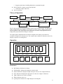
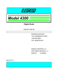
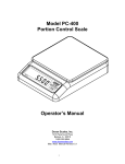
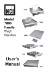
Virtual Measurements & Control
VC210 Service Manual
Safety Notice..................................................................................................................2
Technical Specification.................................................................................................3
Features.........................................................................................................................3
Theory of Operation......................................................................................................4
Operation.......................................................................................................................4
Enunciators .......................................................................................................................... 4
Buttons.................................................................................................................................. 5
Power Down Timer and Buzzer Setting .......................................................................5
Backlight .......................................................................................................................5
Configuration & Calibration ........................................................................................5
Configuration ....................................................................................................................... 6
Calibration ........................................................................................................................... 7
Load Cell Connection ...................................................................................................7
RS232 Connection.........................................................................................................7
RS485 and Current Loop Connection..........................................................................8
Parallel Printer Connection (Centronix) .....................................................................8
Battery Installation .......................................................................................................8
AC Operation / Battery Charging...............................................................................8
Installation Considerations and Restrictions...............................................................8
Warranty Statement.....................................................................................................10
1
Safety Notice
It is important that Virtual Measurements & Control’s equipment is installed and operated in such
a way that all applicable safety requirements are met. It is your responsibility as a user to ensure
that you identify the relevant standards and comply with them. Failure to do so may result in
damages to equipment and personal injury. In particular, you should review the contents of the
User Guide carefully before installing or operating the equipment.
This equipment is not designed for placement in hazardous or explosive environments that
require Factory Mutual Approval.
Under no circumstances will the supplier of the equipment be liable for any incidental,
consequential, or special damages of any kind whatsoever, including but not limited to lost profits
arising from or in any way associated with the use of the equipment or this User Guide.
2
Overview
The VC-210 weight indicator is microprocessor based featuring:
•
•
•
•
•
High resolution weighing
AC or DC power source
Low power consumption
LCD display
Easy operation.
This makes it an ideal choice for an electronic bench or platform scale.
Technical Specification
•
•
•
•
•
•
•
•
•
Accuracy: Class III 5000d (Not type approved)
•
Display:
◊ Backlit LCD
◊ Six characters
◊ Character height/width 22mm (0.88in) / 10 (0.4in)
•
Enunciators:
◊ Low Battery
◊ Stable
◊ Weight Mode
◊ Tare Active
◊ Center Zero
•
•
•
•
•
Power consumption : 0.1VA
A/D conversion speed: 40 samples/sec.
Internal resolution 400,000 counts
Maximum displayed resolution: 1:15000
Non-linear error: < 0.016% F.S
Transducer input range: 1-3 mv/v
Load Cell Excitation: +5VDC
Maximum number of load cells: (4) 350Ω or (10) 1000Ω
Power:
◊ Six AA alkaline batteries (Not included)
◊ Internal 6VDC 1.2Ah lead acid re-chargeable battery (Included)
◊ AC adapter - 12VDC 300mA output (Included)
Operating temperature: 0-40° C
Operating humidity: ≤85%
Dimensions: 210mm (8.4in) L × 140mm (5.6in) H × 88mm (3.52in) W
Approx. Weight: 0.8kg
Features
• Automatic keyboard calibration
• Automatic power shutdown when not in use extends battery life
• Vibration filtering provides a stable weight under adverse conditions
• Automatic lb/kg conversion
• Parallel printer port
3
◊
Supports print features including displayed or accumulated weight
•
RS-232, RS-485, or 20mA current loop (Optional)
◊ Continuous weight output only
•
Auto zero tracking
Theory of Operation
Transducer
Amplifier
A/D
Power Supply
AA battery
LCD display
Microprocessor
Re-chargeable
battery
AC/DC adapter
20mA current ring,
printing RS-232, RS485
Keyboard
The VC-210 provides a strain-gauge transducer with a 5VDC excitation supply. The Wheatstone
bridge configuration of the transducer’s strain gauge provides a resistive change proportional to
the force applied. A DC output signal is derived from the excitation voltage applied across the
bridge that is proportional to the change in resistance.
The output signal is amplified and converted into a digital value which is processed into a
normalized weight by the microprocessor. The weight is then available for indication on the LCD
display or output to a recording device.
Operation
ct
oz
lb
kg
BAT
On
Off
STB
Tare
Figure 2
GROSS
NET
Zero
TARE
Mode
ZERO
ACC
Print series
Panel of the weighing equipment of SME
Print
Enunciators
•
•
•
•
•
•
•
BAT (Battery): Indicates low battery
STB (Stability): Indicates the displayed weight is stable
GOSS: Indicates the displayed weight is the gross value (no tare weight subtracted)
NET: Indicates the displayed weight is the net value (tare weight is subtracted)
TARE: Indicates a tare value is available
ZERO: Indicates center zero
kg (kilograms): Indicates the weight displayed is in kilograms
4
•
•
•
lb (pounds): Indicates the weight is displayed in pounds
oz (ounce): Indicates the weight is displayed in ounces
ct (carat): Indicates the weight is displayed in carats
Buttons
•
ON/OFF: Turns the indicator on or off. A momentary press will turn the unit on when it is
powered down. To turn the unit off press and hold the ON/OFF button for 1.5 seconds,
the battery charge status will be displayed as a percentage ‘bpt 99’ and the unit will power
down.
•
•
TARE: Establishes the current gross weight as a tare value.
•
MODE: Toggles the weight mode between lbs and kgs if unit switching is enabled. Press
and hold the ‘Mode’ button to turn the backlight on or off.
•
PRINT: Prints and accumulates the current weight then counts the transaction. After
printing the transaction count ‘n××’ and accumulated weight ‘YYYYY’ will be displayed
for 1.5 seconds respectively. To clear the transaction count and accumulated weight press
the ‘Zero’ key while the count is displayed.
•
‘ACC PRINT’: for accumulative printing of current weight. After printing the transaction
count ‘n××’ and accumulated weight ‘YYYYY’ will be displayed for 1.5 seconds
respectively. To clear the transaction count and accumulated weight press the ‘Zero’ key
while the count is displayed.
ZERO: Establishes the current gross weight as zero. The allowable zero range is ±2% of
full scale capacity.
Power Down Timer and Buzzer Setting
•
•
•
Insure the calibration jumper is in the Off position (default).
Press the ‘Tare’ button for 1.5 seconds
The indicator will display ‘OFF ××’, where ×× denotes the power down setting 3, 10, 15
or 30 minutes and 0 to disable. Press ‘Print’ to scroll until the desired setting is displayed
then press ‘Mode’ to accept. With the power down time enabled the unit will
automatically power down if there is not weight change or key press in the selected
period of time.
•
The indicator will display ‘bp on’ or ‘bp off indicating the current buzzer status. Press
‘Print’ to select the desired buzzer mode then ‘Mode’ to accept.
•
The indicator will resume the normal weighing mode.
Backlight
•
To toggle the display backlight on and off press and hold the ‘Mode’ key for 1.5 seconds.
Note that enabling the backlight will shorten the battery life.
Configuration & Calibration
To enter the configuration & calibration mode:
•
•
Turn off the VC210 and disconnect the AC adapter.
•
•
Find jumper JP1 and move it to the ‘ON’ position.
Remove the four case screws and carefully open the case. One case screw is found under
the load cell connection panel.
Carefully close the case being careful to not pinch any wiring.
5
•
•
•
•
•
•
Secure the case temporarily with one case screw
Plug in the AC adapter if necessary
Perform the necessary configuration and calibration.
Return JP1 to the ‘OFF’ position.
Carefully close the case being careful not to pinch any wiring.
Secure the case with the case screws.
Configuration
•
•
•
•
•
•
•
Turn on the VC210 and wait for the power up countdown to complete
Press and hold the ‘Tare’ key until the display prompts ‘CAL SP’
Press the ‘Mode’ key, the display will prompt ‘-SET-’
Press the ‘Acc Print’ key to enter the configuration menu
The display will prompt ‘d1 xxx’ or ‘d2 xxx’. Use the ‘Acc Print’ key to toggle to the
‘d1’ setting. The ‘d2 xxx’ selection is reserved for future features.To set the primary
weight division (also referred to as ‘d’ or Countby) press the ‘Print’ key repeatedly until
the desired the weight division (xxx) is displayed. Weight divisions from 0.001 to 50 are
available. Press the ‘Mode’ key to accept the value and advance to the next step. Do not
select a weight division that will cause the scale resolution (capacity / weight division) to
exceed 15000.
The display will prompt ‘n xxxx’ where xxxx is the desired weight resolution (Display
Resolution = Capacity/Weight Divison). If displayed the decimal point is to be ignored
i.e. 12.00 is a display resolution of 1200. To determine the resolution required divide the
desired scale capacity by the weight division.
◊ For example:
(1) If the weight division is set to 0.1 and a 1000 lb capacity is desired set the display
resolution to 1000.0 (10000 = 1000 / 0.1).
(2) If the weigh division is set to 2 and a 5000 lb capacity is desired set the display
resolution to 2500 = (5000/2).
(3) Note that if lb/kg switching is to be allowed set the resolution to the kg value.
◊ To change the resolution:
(1) Press the ‘Acc Print’ key repeatedly until the desired digit is flashing.
(2) Press the ‘Print’ key repeatedly until the desired number is displayed.
(3) Press the ‘Acc Print’ key to advance to the next decade to be changed the ‘Mode’
key to accept and continue to the next step.
◊ Re-calibration will be necessary if the weight division or resolution values are
changed.
The display will prompt ‘Unt yx’ where ‘yx’ represents the unit of measure to be used.
◊ The unit choices are:
(1) 00 kg only
(2) 01 lb only
(3) 02 oz only
(4) 03 ct only
(5) 10 Dual unit of measure with kg as primary (calibration) unit and lb as secondary
unit.
◊ Press the ‘Acc Print’ key until the desired ‘y’ setting is displayed and the ‘Print’ key
until the desired ‘x’ setting is displayed.
◊ Press ‘Mode’ to accept the value and advance to the next setting.
•
The display will prompt ‘b xxxx’ where xxxx is the serial baud rate. Press the ‘Print’ key
repeatedly until the desired baud rate is displayed. 1200, 2400, 4800 and 9600 baud are
available. Press ‘Mode to accept the value.
•
The configuration is completed and the indicator will return to the normal weighing
6
mode.
Calibration
•
•
•
•
Turn on the VC210 and wait for the power up countdown to complete
•
This display will prompt ‘xxxxx’ where ‘xxxxx’ is the weigh value used for the previous
calibration.
◊ To change the calibration weight:
(1) Press the ‘Acc Print’ key repeatedly until the desired digit is flashing.
(2) Press the ‘Print’ key repeatedly until the desired number is displayed.
(3) Press the ‘Acc Print’ key to advance to the next decade to be changed.
•
With the desired calibration weight displayed place the calibration load on the scale. Press
‘Mode’ to establish the span calibration point.
•
The calibration and the indicator will return to the normal weighting mode.
Press and hold the ‘Tare’ key until the display prompts ‘CAL SP’
Press the ‘Acc Print’ key to enter the calibration menu
The display will prompt ‘CAL 00’. Remove all weight from the scale and press ‘Mode’
to establish the zero calibration point.
Load Cell Connection
The load cell connection is made via a round 5 pin quick disconnect. Terminate the load cell to the
mating connector as indicated.
1
5
2
4
3
(1) +Signal
(2) - Signal
(3) AGND shield
(4) +E, +S (+excitation, +sense)
(5) -E, -S (-excitation, -sense)
Back (solder side) View
RS232 Connection
The RS232 serial connection is made via a female D-SUB-9 (DB9) connector.
1 2 3 4 5
OOOOO
OOOO
6 7 8 9
Back (solder side) View
Signal direction at device
(2) RD receive
input
(3) SD transmit
output
(5) SG signal ground
(9) SD 2
input
7
RS485 and Current Loop Connection
The RS485 and current loop connection are made via a male DB15 connector.
1 2 3 4 5 6 7 8
OOOOOOOO
OOOOOOO
9 10 11 12 13 14 15
(2) 485-A
(3) 485-B
(5) Pin GND
(7) Pin I+
(8) Pin I-
Back (solder side) View
Parallel Printer Connection (Centronix)
The parallel printer connection is made via a male DB25
1
2 3 4 5 6 7 8 9 10 11 12 13
O O O O O O O O O O O O O
O O O O O O O O O O O O
14 15 16 17 18 19 20 21 22 23 24 25
Back (solder side) View
(1)
(2-9)
(10,12-18)
(11)
(19-25)
STRB
D0-D7
NC
BUSY
SG
Battery Installation
•
Remove the battery compartment cover found on the top of the VC210 by pressing on the
latching tab and rocking forward.
•
Install six AA (#5) alkaline batteries noting the battery orientation found inside the battery
compartment.
•
Replace the battery compartment cover.
AC Operation / Battery Charging
•
•
Insert the 12V AC adapter jack into the 12V socket on the rear of the indicator.
•
The internal battery is charging while the AC adapter is connected.
Plug the AC adapter into the wall socket. (INSURE THE AC ADAPTOR IS
APPROPRIATE FOR THE SUPPLIED LINE VOLTAGE, 120 or 220 VAC.)
Installation Considerations and Restrictions
•
•
•
Avoid installation in direct sunlight.
Avoid installation in dusty environments.
Avoid installation in areas where serious vibration is present.
8
•
•
•
•
Do not operate on battery power if the ‘BAT’ enunciator is illuminated.
Do not expose the case to strong solvents.
Do not submerge or soak with water.
Return all failures to the factory there are no user serviceable parts.
9
Warranty Statement
Virtual Measurements & Control warrants your VC210 instrumentation, under normal use and
service to be free from defects in material and workmanship for a period of twelve (12) months
from the date of purchase.
If your VC210 instrumentation fails to work properly during the warranty period due to a defect in
materials or workmanship VMC will either repair or replace it at no charge for labor or
materials. Replacement units are provided on an exchange basis and will be either new or
reconditioned at VMC’s discretion.
Warranty service may be obtained by returning or shipping your faulty unit prepaid and insured to
our nearest repair or manufacturing facility.
Failure to exercise caution to protect the equipment from electrostatic discharge damage, adverse
temperature and humidity conditions or physical abuse may void the warranty.
Under no circumstances will the supplier of the equipment be liable for any incidental,
consequential or special damages of any kind whatsoever, including but not limited to lost profits
arising from or in any way associated with the use of the equipment.
10