1
{ServiceManual}{FinalDraft}{HealthImaging}{Internal}
Publication No. 8E8820
03NOV03
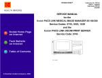
SERVICE MANUAL
for the
Kodak PACS LINK MEDICAL IMAGE MANAGER 100
Service Codes: 3433, 4223 - 1.2 GHz
Kodak PACS LINK MEDICAL IMAGE MANAGER 200
Service Codes: 1539, 4224 - 1.2 GHz
and the
Kodak PACS LINK 25 PRINT SERVER
Service Code: 3754
Restricted Information
© Eastman Kodak Company, 2003
PLEASE NOTE
The information contained herein is based on the experience and knowledge relating to the subject matter
gained by Eastman Kodak Company prior to publication.
No patent license is granted by this information.
Eastman Kodak Company reserves the right to change this information without notice, and makes no
warranty, express or implied, with respect to this information. Kodak shall not be liable for any loss or
damage, including consequential or special damages, resulting from any use of this information, even if
loss or damage is caused by Kodak’s negligence or other fault.
This equipment includes parts and assemblies sensitive to damage from electrostatic
discharge. Use caution to prevent damage during all service procedures.
Table of Contents
Description
Page
System Description. . . . . . . . . . . . . . . . . . . . . . . . . . . . . . . . . . . . . . . . . . . . . . . . . . . . . . . . . . . . . .
1-1
How to Use this Manual . . . . . . . . . . . . . . . . . . . . . . . . . . . . . . . . . . . . . . . . . . . . . . . . . . . . .
1-1
Overview of MIM Types . . . . . . . . . . . . . . . . . . . . . . . . . . . . . . . . . . . . . . . . . . . . . . . . . . . . .
1-3
Printers Used with MIMs . . . . . . . . . . . . . . . . . . . . . . . . . . . . . . . . . . . . . . . . . . . . . . . . . . . .
1-4
Input Options . . . . . . . . . . . . . . . . . . . . . . . . . . . . . . . . . . . . . . . . . . . . . . . . . . . . . . . . . . . . . .
1-5
Input Data Formats Allowed . . . . . . . . . . . . . . . . . . . . . . . . . . . . . . . . . . . . . . . . . . . . . . . . . .
1-5
Output Options . . . . . . . . . . . . . . . . . . . . . . . . . . . . . . . . . . . . . . . . . . . . . . . . . . . . . . . . . . . .
1-5
Maximum Inputs and Outputs . . . . . . . . . . . . . . . . . . . . . . . . . . . . . . . . . . . . . . . . . . . . . . . . .
1-6
User Control . . . . . . . . . . . . . . . . . . . . . . . . . . . . . . . . . . . . . . . . . . . . . . . . . . . . . . . . . . . . . .
1-8
HIPPA Privacy Feature . . . . . . . . . . . . . . . . . . . . . . . . . . . . . . . . . . . . . . . . . . . . . . . . . . . . . .
1-8
“MIM Service Application” Software . . . . . . . . . . . . . . . . . . . . . . . . . . . . . . . . . . . . . . . . . . .
1-8
Service Access . . . . . . . . . . . . . . . . . . . . . . . . . . . . . . . . . . . . . . . . . . . . . . . . . . . . . . . . . . . . .
1-8
MIM 200 and 25 Print Server: Patient Environment. . . . . . . . . . . . . . . . . . . . . . . . . . . . . . . . 1-13
Documentation. . . . . . . . . . . . . . . . . . . . . . . . . . . . . . . . . . . . . . . . . . . . . . . . . . . . . . . . . . . . . 1-16
Tools - Hardware and Software . . . . . . . . . . . . . . . . . . . . . . . . . . . . . . . . . . . . . . . . . . . . . . . . . . . .
2-1
Software Tools . . . . . . . . . . . . . . . . . . . . . . . . . . . . . . . . . . . . . . . . . . . . . . . . . . . . . . . .
2-2
Installing the “Service LAPTOP COMPUTER Software for MIM-Based Products” . .
2-3
Installation and Setup Procedures for LAPTOP COMPUTERS with Windows 98 . . . .
2-9
Installation and Setup Procedures for LAPTOP COMPUTERS with Windows 2000 . . 2-15
Installation and Setup Procedures for LAPTOP COMPUTERS with Windows NT . . . 2-17
Installing “SecureLink” Client Software . . . . . . . . . . . . . . . . . . . . . . . . . . . . . . . . . . . . 2-19
Installing pcAnywhere REMOTE CONTROL SOFTWARE. . . . . . . . . . . . . . . . . . . . . 2-21
Creating a Remote Connection Item for pcAnywhere . . . . . . . . . . . . . . . . . . . . . . . . . . 2-21
Connection Methods . . . . . . . . . . . . . . . . . . . . . . . . . . . . . . . . . . . . . . . . . . . . . . . . . . . . 2-23
Starting and Using “SecureLink” . . . . . . . . . . . . . . . . . . . . . . . . . . . . . . . . . . . . . . . . . . 2-23
Connecting your LAPTOP COMPUTER to a MIM using a SERIAL CABLE - for LAPTOP
COMPUTERS with Windows 98 . . . . . . . . . . . . . . . . . . . . . . . . . . . . . . . . . . . . . . . . 2-25
Connecting your LAPTOP COMPUTER to a MIM using a SERIAL CABLE - for LAPTOP
COMPUTERS with Windows 2000 or Windows NT . . . . . . . . . . . . . . . . . . . . . . . . . 2-27
Connecting your LAPTOP COMPUTER to a MIM with a VPN Connection . . . . . . . . 2-30
Quitting the Service Application . . . . . . . . . . . . . . . . . . . . . . . . . . . . . . . . . . . . . . . . . . 2-32
Starting pcAnywhere on your LAPTOP COMPUTER. . . . . . . . . . . . . . . . . . . . . . . . . . 2-33
Buttons and Hot Keys for pcAnywhere. . . . . . . . . . . . . . . . . . . . . . . . . . . . . . . . . . . . . . 2-36
3-1
Installing the Hardware . . . . . . . . . . . . . . . . . . . . . . . . . . . . . . . . . . . . . . . . . . . . . . . . . . . . . . . . . .
Unpacking System Components . . . . . . . . . . . . . . . . . . . . . . . . . . . . . . . . . . . . . . . . . . . . . . .
3-2
Installing the 25 PS on an 8100 or 8200 LASER IMAGER . . . . . . . . . . . . . . . . . . . . .
3-3
Installing the 25 PS on a Wall . . . . . . . . . . . . . . . . . . . . . . . . . . . . . . . . . . . . . . . . . . . .
3-4
Installing the 25 PS on a Shelf . . . . . . . . . . . . . . . . . . . . . . . . . . . . . . . . . . . . . . . . . . . .
3-5
Connecting a Telephone Line to an INTERNAL MODEM . . . . . . . . . . . . . . . . . . . . . . . . . . 3-37
2
NOV 2003 – 8E8820
Installing an EXTERNALMODEM . . . . . . . . . . . . . . . . . . . . . . . . . . . . . . . . . . . . . . . . . . . . .
Installing a FIBER OPTIC OUTPUT (FOPCIL) BOARD . . . . . . . . . . . . . . . . . . . . . . . . . . .
Installing a COPPER OUTPUT (COPCIL) BOARD . . . . . . . . . . . . . . . . . . . . . . . . . . . . . . .
Network Isolation for MIM 200: 667 MHz, 1 MHz, 1.2 GHz, 2.4 MHz - European . . . . . . .
Primary Ethernet Isolation Connections . . . . . . . . . . . . . . . . . . . . . . . . . . . . . . . . . . . . .
Secondary Ethernet Isolation Connections . . . . . . . . . . . . . . . . . . . . . . . . . . . . . . . . . . .
Patient Environment Connection . . . . . . . . . . . . . . . . . . . . . . . . . . . . . . . . . . . . . . . . . . .
Connecting the KEYPAD to the MODALITY. . . . . . . . . . . . . . . . . . . . . . . . . . . . . . . . . . . . .
Preparing to Apply Power. . . . . . . . . . . . . . . . . . . . . . . . . . . . . . . . . . . . . . . . . . . . . . . . . . . . .
De-energizing the MIM . . . . . . . . . . . . . . . . . . . . . . . . . . . . . . . . . . . . . . . . . . . . . . . . . . . . . .
Energizing the MIM . . . . . . . . . . . . . . . . . . . . . . . . . . . . . . . . . . . . . . . . . . . . . . . . . . . . . . . . .
Upgrading MIM Software . . . . . . . . . . . . . . . . . . . . . . . . . . . . . . . . . . . . . . . . . . . . . . . . . . . . . . . . .
Saving and Restoring the System Set Up . . . . . . . . . . . . . . . . . . . . . . . . . . . . . . . . . . . . . . . . .
Saving and Restoring from a PRINT or DISPLAY KEYPAD . . . . . . . . . . . . . . . . . . . .
Backing up from the TOUCHSCREEN KEYPAD . . . . . . . . . . . . . . . . . . . . . . . . . . . . .
Setting Up the BIOS for the MIM 200 - 667 MHz . . . . . . . . . . . . . . . . . . . . . . . . . . . . .
Setting Up the BIOS for the 25 PS . . . . . . . . . . . . . . . . . . . . . . . . . . . . . . . . . . . . . . . . .
Setting Up the BIOS for the MIM 100 . . . . . . . . . . . . . . . . . . . . . . . . . . . . . . . . . . . . . .
Loading New MIM Application Software (Ghosting) . . . . . . . . . . . . . . . . . . . . . . . . . . . . . . .
Installing MIM DEVICE DRIVERS and FIRMWARE. . . . . . . . . . . . . . . . . . . . . . . . . . . . . .
MIM Privacy Feature . . . . . . . . . . . . . . . . . . . . . . . . . . . . . . . . . . . . . . . . . . . . . . . . . . . . . . . .
Accessing the Security Administrator Console from a Remote COMPUTER . . . . . . . .
Enabling or Disabling the Privacy Feature . . . . . . . . . . . . . . . . . . . . . . . . . . . . . . . . . . .
Setting up a PRINTER . . . . . . . . . . . . . . . . . . . . . . . . . . . . . . . . . . . . . . . . . . . . . . . . . . . . . . . . . . .
Kodak DryView 8100 LASER IMAGER. . . . . . . . . . . . . . . . . . . . . . . . . . . . . . . . . . . . .
Kodak DryView 8200 LASER IMAGER. . . . . . . . . . . . . . . . . . . . . . . . . . . . . . . . . . . . .
Kodak DryView 8700/8500 and 969 HQ LASER IMAGERS and
Kodak DryView 8800 MULTI-INPUT MANAGER. . . . . . . . . . . . . . . . . . . . . . . . . .
Setting Up a PRINT SERVER . . . . . . . . . . . . . . . . . . . . . . . . . . . . . . . . . . . . . . . . . . . . . . . . . . . . .
Creating Network Profiles Using the “MIM Service Application” . . . . . . . . . . . . . . . . .
Setting Up the KEYPAD for Correct Time Zone. . . . . . . . . . . . . . . . . . . . . . . . . . . . . . . . . . .
Completing Configuration of the Destinations . . . . . . . . . . . . . . . . . . . . . . . . . . . . . . . . . . . . .
Parameter Tables. . . . . . . . . . . . . . . . . . . . . . . . . . . . . . . . . . . . . . . . . . . . . . . . . . . . . . . . . . . .
Setting Up a MODALITY SERVER . . . . . . . . . . . . . . . . . . . . . . . . . . . . . . . . . . . . . . . . . . . . . . . .
Setting Up the Input for a VIDEO INTERFACE BOARD . . . . . . . . . . . . . . . . . . . . . . . . . . .
Using Auto Setup to Set up the VIDEO INTERFACE BOARD . . . . . . . . . . . . . . . . . .
Cable Compensation Adjustment for VIDEO 60 and 150LC INTERFACE BOARDS .
Checking Image Quality . . . . . . . . . . . . . . . . . . . . . . . . . . . . . . . . . . . . . . . . . . . . . . . . .
Using Advanced Leveling to Define Black and White Values . . . . . . . . . . . . . . . . . . . .
Adjusting Gain and Offset . . . . . . . . . . . . . . . . . . . . . . . . . . . . . . . . . . . . . . . . . . . . . . . .
Notes on Adjusting Image Quality. . . . . . . . . . . . . . . . . . . . . . . . . . . . . . . . . . . . . . . . . .
Parameter Tables. . . . . . . . . . . . . . . . . . . . . . . . . . . . . . . . . . . . . . . . . . . . . . . . . . . . . . . . . . . .
Checking the HIS/RIS Connection . . . . . . . . . . . . . . . . . . . . . . . . . . . . . . . . . . . . . . . . .
Troubleshooting the HIS/RIS Gateway Connection . . . . . . . . . . . . . . . . . . . . . . . . . . . .
Disabling the HIS/RIS GATEWAY . . . . . . . . . . . . . . . . . . . . . . . . . . . . . . . . . . . . . . . .
Using the BAR CODE READER with HIS/RIS . . . . . . . . . . . . . . . . . . . . . . . . . . . . . . .
Using the BAR CODE READER without HIS/RIS . . . . . . . . . . . . . . . . . . . . . . . . . . . .
Obtaining Optimum Images . . . . . . . . . . . . . . . . . . . . . . . . . . . . . . . . . . . . . . . . . . . . . . . . . . . . . . .
Using the KEYPAD to Create Optimum Images for the SCU . . . . . . . . . . . . . . . . . . . . . . . . .
Setting Up Print Server for True Size Printing - Cropping of Images . . . . . . . . . . . . . . . . . . .
Setting Up the SCU for Cropping . . . . . . . . . . . . . . . . . . . . . . . . . . . . . . . . . . . . . . . . . .
Text Box Relocation . . . . . . . . . . . . . . . . . . . . . . . . . . . . . . . . . . . . . . . . . . . . . . . . . . . . . . . . .
Definitions . . . . . . . . . . . . . . . . . . . . . . . . . . . . . . . . . . . . . . . . . . . . . . . . . . . . . . . . . . . .
Selecting TFT Sets . . . . . . . . . . . . . . . . . . . . . . . . . . . . . . . . . . . . . . . . . . . . . . . . . . . . . .
TFT Set Descriptions . . . . . . . . . . . . . . . . . . . . . . . . . . . . . . . . . . . . . . . . . . . . . . . . . . . .
ULUT Set Selections for the 8300 LASER IMAGER . . . . . . . . . . . . . . . . . . . . . . . . . .
ULUT Set Selections for the 8600 and 8610 LASER IMAGER. . . . . . . . . . . . . . . . . . .
Completing the Installation . . . . . . . . . . . . . . . . . . . . . . . . . . . . . . . . . . . . . . . . . . . . . . . . . . . . . . . .
8E8820 – NOV 2003
3-38
3-40
3-41
3-42
3-42
3-42
3-42
3-43
3-44
3-44
3-44
4-1
4-1
4-2
4-2
4-7
4-8
4-9
4-10
4-14
4-15
4-15
4-16
5-1
5-1
5-2
5-4
6-1
6-6
6-11
6-20
6-20
7-1
7-11
7-31
7-33
7-35
7-36
7-37
7-39
7-48
7-70
7-70
7-70
7-74
7-74
8-1
8-10
8-11
8-11
8-12
8-16
8-16
8-18
8-35
8-41
9-1
3
SERVICE MANUAL
Final Procedures . . . . . . . . . . . . . . . . . . . . . . . . . . . . . . . . . . . . . . . . . . . . . . . . . . . . . . . . . . .
9-1
Objectives . . . . . . . . . . . . . . . . . . . . . . . . . . . . . . . . . . . . . . . . . . . . . . . . . . . . . . . . . . . .
9-2
Training the Security Administrator . . . . . . . . . . . . . . . . . . . . . . . . . . . . . . . . . . . . . . . . . . . .
9-6
Providing Service Feedback . . . . . . . . . . . . . . . . . . . . . . . . . . . . . . . . . . . . . . . . . . . . . . . . . .
9-7
Conversions . . . . . . . . . . . . . . . . . . . . . . . . . . . . . . . . . . . . . . . . . . . . . . . . . . . . . . . . . . . . . . . . . . . 10-1
Troubleshooting. . . . . . . . . . . . . . . . . . . . . . . . . . . . . . . . . . . . . . . . . . . . . . . . . . . . . . . . . . . . . . . . 11-1
Replacing the MIM HARD DRIVE, CD ROM DRIVE, or FLOPPY DRIVE. . . . . . . . . . . . 11-1
Connecting to a MIM . . . . . . . . . . . . . . . . . . . . . . . . . . . . . . . . . . . . . . . . . . . . . . . . . . . . . . . 11-2
Finding an Unknown MIM IP Address . . . . . . . . . . . . . . . . . . . . . . . . . . . . . . . . . . . . . . . . . . 11-2
Tools for Troubleshooting . . . . . . . . . . . . . . . . . . . . . . . . . . . . . . . . . . . . . . . . . . . . . . . . . . . . 11-2
Running a Network “Ping” Test from the “MIM Service Application”. . . . . . . . . . . . . 11-4
Running a Network “DICOM Echo” Test . . . . . . . . . . . . . . . . . . . . . . . . . . . . . . . . . . . 11-5
Running Diagnostics of the INPUT and OUTPUT BOARDS . . . . . . . . . . . . . . . . . . . . 11-6
Changing Level of a Log for Troubleshooting . . . . . . . . . . . . . . . . . . . . . . . . . . . . . . . . 11-7
Retrieving the Activity History Log . . . . . . . . . . . . . . . . . . . . . . . . . . . . . . . . . . . . . . . . 11-8
Interpreting the Activity History Log . . . . . . . . . . . . . . . . . . . . . . . . . . . . . . . . . . . . . . . 11-9
Interpreting the Error History Log . . . . . . . . . . . . . . . . . . . . . . . . . . . . . . . . . . . . . . . . . 11-11
Retrieving the Error Frequency Log . . . . . . . . . . . . . . . . . . . . . . . . . . . . . . . . . . . . . . . . 11-12
Clearing the Error Frequency Log . . . . . . . . . . . . . . . . . . . . . . . . . . . . . . . . . . . . . . . . . 11-13
Viewing Printing Statistics . . . . . . . . . . . . . . . . . . . . . . . . . . . . . . . . . . . . . . . . . . . . . . . 11-13
Troubleshooting with pcAnywhere REMOTE CONTROL SOFTWARE . . . . . . . . . . . . . . . 11-15
Transferring Files Using pcAnywhere REMOTE CONTROL SOFTWARE . . . . . . . . 11-51
Using Windows TASK MANAGER from pcAnywhere REMOTE CONTROL SOFTWARE
11-53
Using NT Event Viewer from pcAnywhere REMOTE CONTROL SOFTWARE . . . . 11-55
Beep Codes . . . . . . . . . . . . . . . . . . . . . . . . . . . . . . . . . . . . . . . . . . . . . . . . . . . . . . . . . . . 11-57
Illustrated Parts List . . . . . . . . . . . . . . . . . . . . . . . . . . . . . . . . . . . . . . . . . . . . . . . . . . . . . . . . . . . . . 12-1
Illustrated Parts Breakdown. . . . . . . . . . . . . . . . . . . . . . . . . . . . . . . . . . . . . . . . . . . . . . . . . . . 12-1
MIM 100 and MIM 200 1.2 GHz Field Replaceable Parts . . . . . . . . . . . . . . . . . . . . . . . . . . . 12-20
Additional Information. . . . . . . . . . . . . . . . . . . . . . . . . . . . . . . . . . . . . . . . . . . . . . . . . . . . . . . . . . . 13-1
Warnings and Cautions. . . . . . . . . . . . . . . . . . . . . . . . . . . . . . . . . . . . . . . . . . . . . . . . . . . . . . . . . . . 14-1
Safety, Regulatory, EMC and CE Marking Compliance. . . . . . . . . . . . . . . . . . . . . . . . . . . . . 14-3
Labels. . . . . . . . . . . . . . . . . . . . . . . . . . . . . . . . . . . . . . . . . . . . . . . . . . . . . . . . . . . . . . . . . . . . 14-3
Kodak PACS LINK MEDICAL IMAGE MANAGER 200
(MIM 200) Safety Requirements Change . . . . . . . . . . . . . . . . . . . . . . . . . . . . . . . . . . . . . . 14-4
Compliancy with IEC 60601-1-1/EN 60601-1-1 Requirements . . . . . . . . . . . . . . . . . . . . . . . 14-4
Setup Diagram . . . . . . . . . . . . . . . . . . . . . . . . . . . . . . . . . . . . . . . . . . . . . . . . . . . . . . . . . . . . . 14-5
Non-Compliancy with IEC 60601-1-1/EN 60601-1-1 Requirements . . . . . . . . . . . . . . . . . . . 14-6
4
NOV 2003 – 8E8820
System Description
Section 1: System Description
Introduction
This manual provides instructions for installation and maintenance of Kodak PACS LINK MEDICAL IMAGE MANAGERS
(MIMs) with V_6.1 and higher software. These systems include the:
• Kodak PACS LINK MEDICAL IMAGE MANAGER 200 (MIM 200)
• Kodak PACS LINK MEDICAL IMAGE MANAGER 100 (MIM 100)
• Kodak PACS LINK 25 PRINT SERVER (25 PS)
Note
The name “MIM,” as used in this manual, applies to all of the above devices.
Note
For MIM service manuals that apply to software versions older than V_6.1, See “Documentation” on Page 1–16.
How to Use this Manual
This manual includes 14 sections:
• Section 1 provides a general description of MIMs.
• Section 2 describes the hardware and software used as tools for installation and service.
• Sections 3 through 9 provide instructions for installing and setting up MIM SYSTEMS. The Field Engineer (FE) will not
need all of these sections for every MIM. The sections cover “types” of MIM: PRINT SERVER, MODALITY SERVER
or COMBINATION BOX. See Figure 1–1. For example, to install a MODALITY SERVER, reference to Sections 5 and 6
is not necessary.
• Section 10 includes procedures for changing MIM configurations.
• Section 11 includes procedures for troubleshooting a MIM.
• Section 12 provides parts information for V_6.1 and higher software.
• Section 13 provides additional information.
• Section 14 provides Warnings and Cautions
8E8820 – NOV 2003
1-1
SERVICE MANUAL
Figure 1–1
1-2
Installing and Setting Up a MIM
NOV 2003 – 8E8820
System Description
Overview of MIM Types
MIMs operate as MODALITY SERVERS, PRINT SERVERS, or both. See Table 1–1.
Table 1–1
MIM Primary Functions
Device
MODALITY SERVER
PRINT SERVER
MIM 200
x
x
MIM 100
x
25 PS
x
• MODALITY SERVERS capture images from digital or video MODALITIES. They have the ability to add annotation to
the images and develop STUDIES that include patient demographic data. The STUDIES are converted to DICOM 3.0 and
sent to WORKSTATIONS, ARCHIVES, and PRINTERS or PRINT SERVERS on the network. See Figure 1–2.
• PRINT SERVERS receive DICOM 3.0 print-class images from remote users on a DICOM/Ethernet NETWORK, convert
these images to the protocol required by a local PRINTER, and send the images to the PRINTER.
Note
The MIM 200 can operate as both a MODALITY SERVER and PRINT SERVER. When it is set up to do so, it is identified as
a COMBINATION BOX. The MIM 200 1.2 GHz only functions as either a MODALITY SERVER or a PRINT SERVER, but
not a COMBINATION BOX.
A COMPUTER using Windows 2000 and application software from Kodak controls and processes the functions of the MIM.
Special purpose INPUT and OUTPUT BOARDS are added to the COMPUTER for external communication.
The MIM does not include a MONITOR, KEYBOARD or MOUSE. For access to the MIM for service, the FE must connect:
• A LAPTOP COMPUTER, or
• A MONITOR KIT that includes a MONITOR, KEYBOARD, and MOUSE.
Figure 1–2
Example MIM 200 667 MHz, 1.4 GHz, and 2.4 GHz Setup
or VIDEO
Digital orDIGITAL
Video Modalities
MODALITIES
(Non-DICOM)
KEYPADS
Keypadsor
or HOST
Host Control
Consoles
CONTROL
CONSOLES
Keypad or
Host Control
Console
MIM
Modality
Server
M9410
Kodak
Kodak
Laser
LASER
Imager
IMAGER
Fiber Optic
or Copper
MODALITY SERVER
DICOM Net
DICOM
DICOM
Printer
PRINTER
DICOM
DICOM
Printer
PRINTER
DICOM 3.0 Print
Class
9410-01L
8E8820 – NOV 2003
1-3
SERVICE MANUAL
Printers Used with MIMs
The software version listed in the table indicates the minimum software version required for each product.
Table 1–2
PRINTER from PRINT SERVER Cross-Reference Chart
PRINTER
Print
Type
Output Data Format
Interface
CABLES
MIM 200
Kodak Ektascan 1120 LASER PRINTER
Laser
Optical Interface
Print Request
Fiber Optic
3.2
Kodak Ektascan 2180 LASER PRINTER
Laser
Optical Interface
Print Request
Fiber Optic
3.2
Kodak Ektascan 160 LASER IMAGER
Laser
Ethernet HOSTCOM
Ethernet
3.2
25 PS
Kodak DryView 8100 LASER IMAGER
Laser
952/COPCIL
Copper
5.0
5.0
Kodak DryView 8200 LASER IMAGER
Laser
DICOM
Ethernet
4.0, 4.1
5.0
Kodak DryView 8300 LASER IMAGER
Laser
952/COPCIL
Copper
5.0
5.2
Kodak DryView 8500 LASER IMAGER / PLUS Laser
Superset or 952/ FOPCIL Fiber Optic
5.0
5.0
Kodak DryView 8500 LASER IMAGER /
STANDARD
Laser
Superset or 952/COPCIL Copper
5.0
5.0
Kodak DryView 8600 LASER IMAGER
Laser
Superset or 952/COPCIL Copper
5.2
5.2
Kodak DryView 8610 LASER IMAGER
Laser
Superset or 952/COPCIL Copper
5.0
5.2
Kodak DryView 8700 LASER IMAGER / PLUS Laser
Superset or 952/ FOPCIL Fiber Optic
5.0
5.0
Kodak DryView 8700 LASER IMAGER /
STANDARD
Laser
Superset or 952/
COPCIL
5.0
5.0
Kodak DryView 8800 MULTI-INPUT
MANAGER
Laser
Superset or 952/ FOPCIL Fiber Optic
5.0
Kodak DryView 969 HQ LASER IMAGER
Laser
Superset or 952/FOPCIL Fiber Optic
5.0
Kodak DryView 969 HQT LASER IMAGER
Laser
Superset or 952/
COPCIL
5.0
1-4
Copper
Copper
NOV 2003 – 8E8820
System Description
Input Options
MIMs use the following interfaces for input of images:
Video Input:
A VIDEO INTERFACE BOARD is necessary.
Digital Input:
A DIGITAL INTERFACE BOARD which receives 8-bit Grayscale images is necessary.
Input from Network:
An Ethernet 10/100baseT circuit in the MIM connects to an Ethernet 10baseT or 100baseT
NETWORK. The network connection is used for image input when the MIM is set up as a PRINT
SERVER. Images received from the network must conform to DICOM 3.0 print-class protocol.
Input Data Formats Allowed
• Point-to-Point Grayscale Video
• Point-to-Point Color Video
• Point-to-Point Grayscale Digital
• KEYPAD Study Management Requests
• Autofilming: KCL, Siemens, 952/831, Hitachi, Toshiba, YMS
• DICOM Print Request: Grayscale or Color
• DICOM Part 10 File
• Patient Demographics: KEYPAD, KEYBOARD, HIS/RIS Broker
• DICOM MODALITY Worklist Management SCU: TOUCHSCREEN KEYPAD
• 3M
Output Options
Network Output:
A NETWORK INTERFACE PORT on the MIM provides the connection for an Ethernet
10baseT or 100baseT NETWORK. A MIM can be set up to send images to as many as 25 print
or store destinations on the network.
Local PRINTER Output:
The following options are available for output to a local PRINTER. Only one output BOARD
can be included in a MIM.
Fiber Optic Output:
A FIBER OPTIC OUTPUT BOARD (FOPCIL) is used to drive LASER IMAGERS from
Kodak with fiber optic inputs. The FOPCIL provides a digital output interface to match the
digital input interface in LASER IMAGERS from Kodak. Both image and COM outputs are
fiber optic. 2180 and 1120 LASER PRINTERS require a single FIBER OPTIC CABLE, and are
driven by an OPTICAL INTERFACE BOARD.
Copper Output:
A COPPER OUTPUT BOARD (COPCIL) is used to drive LASER IMAGERS from Kodak
with copper image and COM inputs. The COPCIL provides a digital output interface to match
the digital input interface in these LASER IMAGERS.
Ethernet Output:
An Ethernet BOARD and CROSSOVER CABLE are used to drive the 8200 LASER IMAGER,
the 160 LASER IMAGER, and the 3600 DMI.
8E8820 – NOV 2003
1-5
SERVICE MANUAL
Output Data Formats Allowed
• DICOM Basic Grayscale Print Management SCU: TOUCHSCREEN and PRINT KEYPAD
• DICOM Color Print Management SCU: TOUCHSCREEN and PRINT KEYPAD
• DICOM Secondary Capture Grayscale and Color Image Store SCU: TOUCHSCREEN KEYPAD
• MIM Optical Interface Print Request: 2180 and 1120 LASER PRINTER
• 10/100baseT Ethernet HOSTCOM Print: 160 LASER IMAGER
• 10/100baseT Ethernet DICOM Print: 8200 LASER IMAGER
• COPCIL: 8700 and 8500 LASER IMAGERS/STANDARD; and 8600, 8610, 8300, and 8100 LASER IMAGERS
• FOPCIL: 8700 and 8500 IMAGERS/PLUS, 8800 MULTI-INPUT MANAGER, and 969 HQ LASER IMAGER
Maximum Inputs and Outputs
Maximum inputs and outputs allowed for MIMs are described in Table 1–3.
Table 1–3
Maximum Inputs and Outputs for MIMs
MIM
200
Function
Maximum Outputs
2 direct - Video or Digital.
1 network - DICOM
1 - Fiber, Copper, or Ethernet
output
MODALITY SERVER (SCU) or PRINT 2 direct - Video or Digital.
SERVER (SCP)
1 network - DICOM
1 - Fiber, Copper, or Ethernet
output
100
MODALITY SERVER (SCU)
1 direct- Video or Digital
1 - DICOM
100 1.2 GHz
MODALITY SERVER (SCU)
2 direct- Video or Digital
1 - DICOM
PRINT SERVER (SCP)
1 network- DICOM
1 - Fiber, Copper, or Ethernet
output
200 1.2 GHz
25 PS
1-6
MODALITY SERVER (SCU), PRINT
SERVER (SCP), OR COMBINATION
Maximum Inputs
NOV 2003 – 8E8820
System Description
INPUT and OUTPUT BOARDS
The INPUT and OUTPUT BOARDS used in MIMS are identified in Table 1–4.
Table 1–4
INPUT and OUTPUT BOARDS
Type of BOARD
MIM 200 MIM 200 MIM 200 MIM 200 MIM 100 MIM 100
2.4 GHz
1 GHz
1.2 GHz 667 MHz 433 MHz 1.2 GHz
25 PS
Input
PRIMARY Ethernet 10/100base T
*
*
*
NETWORK ISOLATION (EEC
countries)
x
x
x
VIDEO 60 INTERFACE
x
x
VIDEO 150LC INTERFACE
x
x
*
x
x
*
x
x
x
VIDEO 150 INTERFACE
DIGITAL INTERFACE
*
x
x
x
x
x
x
x
SECONDARY Ethernet 10/100base T
x
x
x
x
x
FIBER OPTIC OUTPUT (FOPCIL)
x
x
x
x
x
COPPER OUTPUT (COPCIL)
x
x
x
x
x
x
x
x
x
x
x
Output
MIM OPTICAL INTERFACE
Communication
RS422 SERIAL I/F, 8-Channel
x
x
x
POWER/RS422 DIST., 2-Channel
RS-422, 1-Channel
MODEM***
x
x
x
x
x
x
x
x
* PRIMARY Ethernet connection is on the MOTHERBOARD of the COMPUTER.
*** An EXTERNAL MODEM is an option on the MIM 200 - all, 25PS, and MIM 100 1.2 GHz.
Note
For MIM’s with software V_6.1 and higher, the boards must be installed in the correct slots in order for the system to boot. See
“MIM 200, 1.2 GHz - BOARDS” on Page 12–6 and “MIM 100, 1.2 GHz - BOARDS” on Page 12–7.
8E8820 – NOV 2003
1-7
SERVICE MANUAL
MODEM for Remote Service Access
To provide FEs with remote access, an optional MODEM can be included in MIMs. For MIMs manufactured with V_6.1
software, an external MODEM is used. An external MODEM is used on the MIM 100 when installed outside the U.S. or Canada.
An internal MODEM BOARD is used in the MIM 100 within the U.S. and Canada.
If 2 or more MIMS are connected on an Ethernet NETWORK, a MODEM is necessary for only one of the MIMs. To connect
to a MIM without a MODEM, the FE makes a call to the MIM with the MODEM. The call can then be routed to any other MIM
on the network.
User Control
Operators use either a KEYPAD or a host control CONSOLE to acquire images, select output destinations, and print the images.
There is a separate KEYPAD or host control CONSOLE for each directly-connected MODALITY.
MIMs can use 3 types of KEYPADS:
• TOUCHSCREEN KEYPAD - Used to control STUDY creation from a directly-connected MODALITY. This KEYPAD
provides a number of features, including patient demographic acquisition for STUDY delivery to WORKSTATIONS and
ARCHIVES. Only this KEYPAD can be used to send STUDIES to DICOM store destinations.
• PRINT KEYPAD - Used to control STUDY creation from a directly-connected MODALITY for delivery to
print-only destinations such as LASER PRINTERS and LASER IMAGERS.
• DISPLAY KEYPAD - Used only for setup and STUDY management for a MIM operating as a PRINT SERVER, for which
there is only a DICOM interface for STUDY acquisition.
For more information on user control, see the User’s Guides for the MIMs.
HIPPA Privacy Feature
V_6.1 MIM software, includes a privacy feature that allows MIM users to comply with requirements of the Health Insurance
Portability and Accountability Act (HIPPA). When the privacy feature is enabled, keypad operators must log in with a username
and password to use keypad functions that provide access to patient protected health information. The privacy features are
controlled from a “security console” web page that is resident on each MIM. A customer security administrator, working on a
computer connected to the same local area network as the MIM, can access the “security console” web page to setup username/
password accounts for each MIM keypad operator.
“MIM Service Application” Software
The “MIM Service Application” can be used by FEs to:
• Enter parameters for configuration of a MIM during installation.
• Do system management functions, such as backup and restore of configuration parameters.
• Do diagnostics such as viewing logs, running tests, and monitoring operation of the system.
The “MIM Service Application” is stored on the LAPTOP COMPUTER as well as in the MIM. For more information on this
and other tools for service, refer to Section 2, Tools - Hardware and Software.
Service Access
The MIM does not include a MONITOR, KEYBOARD or MOUSE. For access to the MIM for service, the FE must:
• Connect a LAPTOP COMPUTER, or
• Connect a MONITOR KIT that includes a MONITOR, KEYBOARD, and MOUSE.
The MONITOR KIT connects directly to PORTS on the MIM. The LAPTOP COMPUTER can connect to the MIM:
• Over a dial-up serial line connection.
• Over an Ethernet network. The LAPTOP COMPUTER must contain an Ethernet interface for this connection.
• Over a dial-up telephone line using a MODEM.
1-8
NOV 2003 – 8E8820
System Description
When the LAPTOP COMPUTER is connected to a MIM, the FE can use it to run the “MIM Service Application.” Also, via
pcANYWHERE, the FE can use Windows FEATURES such as Windows EXPLORER, Windows EVENT VIEWER, and
Windows TASK MANAGER on the target MIM.
Note
The MONITOR KIT can also be used for service access:
• The “MIM Service Application” can be run with the MONITOR KIT because the service software is stored on the MIM as
well as on the LAPTOP COMPUTER.
• The MONITOR KIT can be used to watch the boot process and access the BIOS on the MIM.
When a MONITOR KIT is used, a LAPTOP COMPUTER with “SecureLink” is also required to unlock the Windows
DESKTOP.
8E8820 – NOV 2003
1-9
SERVICE MANUAL
Setting Up the MIMs
The following figures provide examples of systems using MIMs.
Figure 1–3
MIMs and other Devices on the Network
FIBER OPTIC CABLE
DICOM over Ethernet
Imaging
Device
HIS/RIS
DICOM
ARCHIVE
DEVICE
Digital
Data
DICOM
Imaging
Device
Color or
Grayscale
Video
MIM 200
Autofilming
Link
MIM 100
8500 or 8700
LASER IMAGER
DICOM
WORKSTATION
DISPLAY
KEYPAD
DICOM
25 Print Server
8120 LASER IMAGER
Imaging
Device
Digital
Data
Autofilming
Link
Imaging
Device
CROSSOVER
ETHERNET
CABLE
DICOM
Color or
Grayscale
Video
MIM 200
Autofilming
Link
DISPLAY
KEYPAD
8200 LASER IMAGER
MIM 200
RS-422
COPPER
CABLE
DICOM
MIM 200
8300 or 8610
DISPLAY
KEYPAD LASER IMAGER
H180_3003ECA
H180_3003EC
1-10
NOV 2003 – 8E8820
System Description
Figure 1–4
MODALITY SERVERS
DICOM over Ethernet
PRINT
KEYPAD
Digital Data
Imaging
Device
Digital Data
Imaging
Device
DICOM
MIM 200
PRINT
KEYPAD
PRINT
KEYPAD
Digital Data
Imaging
Device
Autofilming
Link
Color or
Grayscale
Video
Imaging
Device
DICOM
Autofilming
Link
MIM 200
Print
Keypad
TOUCHSCREEN
KEYPAD
FORMAT=
24
COPIES=
1
END
EXAM
MAIN
MENU
Digital Data
Imaging
Device
Autofilming
Link
Color or
Grayscale
Video
Imaging
Device
DICOM
Autofilming
Link
MIM 200
TOUCHSCREEN
KEYPAD
FORMAT=
24
COPIES=
1
END
EXAM
MAIN
MENU
H180_3004EC
8E8820 – NOV 2003
1-11
SERVICE MANUAL
Figure 1–5
MODALITY SERVER, PRINT SERVER, and COMBINATION BOXES
DICOM over Ethernet
PRINT
KEYPAD
Imaging
Device
DICOM
TOUCHSCREEN
KEYPAD
Grayscale
Video
FORMAT=
24
COPIES=
1
PACS Link
MEDICAL IMAGE MANAGER 200
RS-422
COPPER
CABLE
DISPLAY
KEYPAD
MIM 200
8100 LASER IMAGER
END
EXAM
MAIN
MENU
Imaging
Device
PACS Link
MEDICAL IMAGE MANAGER 200
Grayscale
Video
Imaging
Device
Grayscale
Video
MIM 200
PACS Link
DICOM
PRINT
KEYPAD
Imaging
Device
MEDICAL IMAGE MANAGER 200
Grayscale
Video
Ethernet
CABLE
DISPLAY
KEYPAD
MIM 200
160 LASER IMAGER
PRINT
KEYPAD
PRINT
KEYPAD
Imaging
Device
Grayscale
Video
PACS Link
DICOM
Imaging
Device
MEDICAL IMAGE MANAGER 200
Grayscale
Video
RS-422
COPPER
CABLE
Display
Keypad
MIM 200
8100 LASER IMAGER
PRINT
KEYPAD
H180_0082EC
1-12
NOV 2003 – 8E8820
System Description
MIM 200 and 25 Print Server: Patient Environment
Minimum Distance between the MIM 200 or
25 Print Server and the Patient Contact Equipment
Figure 1–6
1.83 m
(6 ft)
Warning
The following installation requirements must be met
worldwide for the MIM 200 and the 25 Print Server and their
accessories; e.g., keypads, footswitches, keyboards. Refer to
the illustration at the left, which identifies the patient
environment.
• Minimum distance from device or accessory to Patient
Contact Equipment; e.g., Ultrasound:
– Horizontal: 1.83 m (6 ft)
– Vertical: 2.5 m (8 ft) above the floor under the
patient
• Contact of patient and device or accessory
simultaneously by caregiver is not allowed.
2.5 m
(8 ft)
• Direct electrical connection between device or accessory
and Patient Contact Equipment is not allowed.
Note
The requirements are based on the EN60601-1 Standard.
1.83 m
(6 ft)
H174_0043GC
8E8820 – NOV 2003
1.83 m
(6 ft)
Important
The MIM 100 can be installed within the patient
environment.
MIM 200 product placement in the European Economic
Community (EEC), see “Kodak PACS LINK MEDICAL
IMAGE MANAGER 200 (MIM 200) Safety Requirements
Change” on Page 14–4.
1-13
SERVICE MANUAL
History of Software
Table 1–5
Versions of Software for the MIM
Version
V_1.x
Features of Software
Original version, for MIM 100 only. Developed for the SPOOLER for DICOM PRINTERS market. Used the CP
DICOM Input Package to connect with the XLP, 1120, and 2180 LASER PRINTERS over the network. Used
DICOM to connect to MLP 190. Features included:
• Grayscale video image acquisition, 8-bit, 1-150 MHz
• Digital image acquisition, 8-bit
• DICOM Basic Grayscale Print Management SCU
• Autofilming control: 952, P831, KCL, Hitachi, YMS, Toshiba, and Siemens
• Image delivery to a single destination chosen from a list of all available destinations
• 10baseT-twisted pair, 10base2-thinnet, 10base5-thicknet using TCP/IP
V_2.x
For MIM 100 only. Developed for the Image Distribution for Diagnosis and Review market. Added:
• 12-bit digital image acquisition
• DICOM Store SCU for Study Delivery to WORKSTATIONS and ARCHIVES
• DICOM Worklist SCU for HIS/RIS Gateway access to retrieve patient demographics
• Manual patient demographics entry via TOUCHSCREEN KEYPAD or full KEYBOARD
• Automated patient demographics entry via HIS/RIS Gateway connection
• Delivery to multiple destinations chosen from a list of all available destinations
• Study re-delivery to any available destination
• Native 100baseT support
• Software licensing ability
V_3.x
Introduced MIM 50 and DPS. Developed for the DMI market and the DICOM SPOOLER for CP-Based
PRINTERS application. Supported connection to the 3600 DMI and 1200 DMI. Added:
• DICOM Basic Grayscale and Color Print SCP for receiving DICOM print jobs
• DICOM Basic Annotation Box SCP for receiving text
• Low Cost Color/Grayscale VIDEO 60 INTERFACE BOARD
• Output to CP-Based PRINTERS via high-speed fiber connection
V_3.2
Introduced MIM 200. Developed for the LSI, DMI, and PACS (Cemax-ICON) business applications. Added:
• Multiple direct connect inputs with or without DICOM input
• Ability to acquire a mix of color and monochrome images on a single page
• 9410 ACQUISITION SYSTEM MS emulation for 952 Autofilming Superset support
• Connection database to provide user with ability to set image processing preferences within the spooler, source
by source
• Ability to create separate image series within a “study” for delivery to AutoRad WORKSTATIONS
• DICOM Presentation PLUT support for interoperability with 9410 ACQUISITION SYSTEM
V_4.x
Added the ability to operate as a DPS for the 8200 LASER IMAGER, and features that can:
• Support standard multi-up page formats used by the Kodak Directview CR 800 SYSTEM for DICOM delivery.
• Rasterize page annotation tests, using a clear, sharp, true-size font onto a predefined location centered on the
bottom of the page.
• Use the “MIM Service Application” for configuration of an 8200 LASER IMAGER and a networked PRINT
SERVER/8200 LASER IMAGER destination.
V_5.0
1-14
Adds to MIMs the features of the 9410 ACQUISITION SYSTEM and the 9405 PRINT SERVER, allowing a
MIM to be a replacement for these in systems that connect to Kodak DryView LASER IMAGERS. This release
allows connection to the 8700, 8500, 8610, 8300, 8200, and 8100 LASER IMAGERS as well as the 8800
MULTI-INPUT MANAGER, 160 LASER IMAGER and 969 HQ LASER IMAGER.
NOV 2003 – 8E8820
System Description
Version
Features of Software
V_5.2
Adds the features of cropping CR and DR images from Kodak and other manufacturer’s systems including FUJI
CR to provide true size printing using the MIM Print Servers.
The MIM Print Servers have expanded Kodak DryView printer destinations including the 8300, 8600, and 8610
for the 25 Print Server and 8600 for the MIM 200 Print Server.
A bar code reader option is supported on the modality servers, MIM 100 and MIM 200, to improve workflow for
patient demographics.
A network isolation board has been added to the MIM 200 for the European region.
V_6.0
Adds Privacy-Enable features to the MIMs for those customers desiring this feature. Expected usage is in DICOM
Store and DICOM Worklist management applications. Also, the privacy feature may be used for the reprint
capability of DICOM print applications. The privacy feature is optional and can be disabled.
Incorporates SecureLink authentication and encryption for service connections to the MIM.
Changes operating system on MIMs from Windows NT to Windows 2000.
V_6.0 supports only the following MIM platforms:
• MIM 100 - 433 MHz
• MIM 200 - 667 MHz
• MIM 200 1.0 GHz
• MIM 200 2.4 GHz
• Kodak PACS Link 25 Print Sever
With V_6.0, the following items no longer supported:
• MIM 50
• DPS (DICOM Print Server)
• Kodak 3600 DESKTOP MEDICAL IMAGER
• Kodak 1200 DESKTOP MEDICAL IMAGER
Supports VPN remote access.
Film border default setting = Image Dmax for 2180, 8900 and 160 applications.
Date annotation format is configurable according to international requirements.
Printing of patient demographics in the quotation box, at the bottom of the film, if DICOM Store is enabled.
HISRIS enhancements:
- Polling interval can be configured
- Record retention window can be configured
- Enable/disable scheduled procedure step start time
- Enable/disable Study Description
V_6.1
• Adds support for embedded enclosure
• Improves workflow for bar code reader by allowing use from Acquisition screen.
• Uses image capture time in DICOM study date/time and page annotation date/time.
• Supports underscore character in AE Title
8E8820 – NOV 2003
1-15
SERVICE MANUAL
Specifications
For machine specifications, see the SITE SPECIFICATIONS document for the MIM.
Documentation
Publication
SITE
SPECIFICATIONS
QUICK REFERENCE
SERVICE MANUAL
USER GUIDES
Product
Pub. No.
Notes
8E9891
Kodak PACS LINK MEDICAL IMAGE
MANAGER 100 and 200, and Kodak PACS LINK NOV03
25 PRINT SERVER
QUICK REFERENCE GUIDE for the KODAK
PACS LINK MEDICAL IMAGE
MANAGER with DISPLAY KEYPAD
QUICK REFERENCE GUIDE for the KODAK
PACS LINK MEDICAL IMAGE
MANAGER 200 with PRINT KEYPAD
QUICK REFERENCE GUIDE for the KODAK
PACS Link 25 PRINT SERVER
QUICK REFERENCE GUIDE for the KODAK
PACS LINK MEDICAL IMAGE
MANAGER TOUCH SCREEN KEYPAD
Kodak PACS LINK MEDICAL IMAGE
MANAGER 100/200, Kodak PACS LINK 25
PRINT SERVER
Introduction to the Kodak PACS LINK
PRODUCTS
USER’S GUIDE for the DISPLAY KEYPAD - for
use with KODAK PACS LINK MEDICAL
IMAGE MANAGER 200 and KODAK PACS
LINK 25 Print Server
USER’S GUIDE for the PRINT KEYPAD - for use
with the KODAK PACS LINK MEDICAL
IMAGE MANAGER 20
USER’S GUIDE for the TOUCH SCREEN
KEYPAD - for use with the KODAK PACS LINK
MEDICAL IMAGE MANAGER 100 and 200
Security and Privacy Features - for use with the
KODAK PACS LINK MEDICAL IMAGE
MANAGER and 25 Print Server
Security Policy, Customer Security Obligations
and Best Practices
USER’S GUIDE ADDENDUM for SOFTWARE
VERSION 6.1 - for KODAK PACS LINK
8E8681
JUL03
LAMINATED CARD
8E8682
JUL03
8E8684
JUL03
8E8683
JUL03
8E8820
NOV03
CD for systems with V_6.1
application software.
8E8676
JUL03
8E8678
JUL03
8E8679
JUL03
8E8680
JUL03
8E9002
JUL03
8E9122
JUL03
8E9892
NOV03
MEDICAL IMAGE MANAGER 100 and 200
1-16
NOV 2003 – 8E8820
System Description
Glossary
10/100baseT
A CSMA/CD Ethernet LAN using Twisted Pair Wire with a baseband of either 10 Mbps or
100 Mbps. The IEEE standard for 24-gauge UTP for Ethernet.
ANSI
American National Standards Institute
ASL
Adaptive Speed Leveling: ASL keeps the MODEM on-line, operating at the highest possible speed and
constantly checking data integrity.
AUI
Attachment Unit Interface: A 15-pin CONNECTOR, usually with a transceiver, used with Ethernet
connection.
AWG
American Wire Gauge
CP
Common Protocol
CPOI
Common Protocol Optical Interface
CSMA/CD
Carrier Sense Multiple Access / Collision Detection
DICOM
The Digital Imaging and Communications in Medicine imaging standard.
DMI
DESKTOP MEDICAL IMAGER
EEC
European Economic Community
EIA
Electrical Industries Association
Ethernet
A passive COAXIAL CABLE that sends digital signals for a network in which the interconnections contain
active elements. A LAN standard that uses a BUS topology with CSMA/CD access control. A LAN that can
bridge operating systems and ignore inherent differences in data and file structures to promote reliable
interconnections.
HIS/RIS
Hospital Information System / Radiology Information System
HUB
A central point or concentrator in a star topology where connections meet. Network communications flow
through the HUB.
IP
Internet Protocol
LAN
Local Area Network: A combination of COMPUTER hardware and software that connects several
COMPUTERS and peripherals to provide communication and access to shared data.
LUT
Lookup Table
MIM
Medical Image Manager
MODALITY
An Imaging Device.
MODEM
Modulator / Demodulator: A device that your COMPUTER uses to send data over TELEPHONE WIRES.
Mbps
Megabits per second
NEMA PLUG
The National Electrical Manufacturer’s Association standard 3-pronged PLUG.
OI
Optical Interface
PACS
Picture Archiving & Communication Systems
PLUT
Presentation Lookup Table
Pre-staged
Equipment that was shipped with the MODALITY parameters installed and tested.
Protocol
Set of rules and procedures allowing COMPUTERS and peripherals to communicate.
Qualified Input The MODALITY has been field tested with correct parameters. The database in the Service Software for
the MIM might also include this MODALITY in the Qualified list.
RJ-11
4-WIRE MODULAR CONNECTORS for phone lines.
RJ-45
8-WIRE MODULAR CONNECTORS for Ethernet twisted-pair wiring.
RS-232, RS-422 EIA standards for physical and electrical specifications of a serial interface between a COMPUTER and a
peripheral, for example, a MODEM.
RS-485
EIA standard for digital data connections between devices.
SCU
DICOM Service Class User.
SCP
DICOM Service Class Provider.
8E8820 – NOV 2003
1-17
SERVICE MANUAL
TCP/IP
Transmission Control Protocol / Internet Protocol: Set of communication protocols developed for the
Defense Advanced Research Projects Agency (DARPA) to connect dissimilar systems. The TCP controls
the transfer of the data, and the IP provides the routing mechanism.
TFT
Transfer Function Table
TSC
Technical Support Center
TSK
TOUCHSCREEN KEYPAD - Liquid Crystal Display (LCD) screen.
Twisted Pair
Wiring used in telephone systems and many networks, consisting of a pair of COPPER WIRES twisted
around each other to counteract the effects of noise. Commonly used instead of coaxial Ethernet cable in
network applications. Usually unshielded; however, the more expensive shielded version supports greater
distance with less risk of electrical interference.
ULUT
User Lookup Table
Unqualified
Input
The MODALITY has not been field tested.
UTP
Unshielded Twisted Pair
WAN
Wide Area Network
1-18
NOV 2003 – 8E8820
Tools - Hardware and Software
Section 2: Tools - Hardware and Software
Introduction
This section provides information about the tools used for installation and service of the:
• Kodak PACS LINK MEDICAL IMAGE MANAGER 200 (MIM 200)
• Kodak PACS LINK MEDICAL IMAGE MANAGER 100 (MIM 100)
• Kodak PACS LINK 25 PRINT SERVER (25 PS)
The information in this section includes:
Lists of hardware and software tools
Procedures for configuring the LAPTOP COMPUTER
Procedure for installing new MIM Service Application software
Procedure for installing “SecureLink” authentication software
Procedure for installing pcAnywhere REMOTE CONTROL SOFTWARE
Procedures for connecting your LAPTOP COMPUTER to a MIM
Description of “MIM Service Application” functions
Procedures for starting the “MIM Service Application”
Using pcAnywhere REMOTE CONTROL SOFTWARE
Procedure for using a MONITOR KIT
8E8820 – NOV 2003
2-1
SERVICE MANUAL
Tools and Accessories
Hardware Tools
Item
1.
2.
3.
4.
5.
6.
7.
8.
9.
10.
11.
12.
13.
Part Number
LAPTOP COMPUTER - Must have Windows 98, Windows 2000 or Windows NT.
SERIAL CABLE - Use to connect LAPTOP COMPUTER to MIM SERIAL PORT
10bT/100bT Ethernet BOARD - Installed in LAPTOP COMPUTER
NETWORK CROSSOVER CABLE
10 baseT CABLE
Ethernet HUB: 10bT/100bT
MONITOR KIT - A MONITOR, KEYBOARD and MOUSE
ADAPTER - Used to connect MONITOR CABLE to the MIM 200, 667 MHz version.
Y CABLE - Used to connect KEYBOARD and MOUSE of MONITOR KIT to 25 PS
or MIM 100.
EXTERNAL CD ROM DRIVE - Used to upgrade new software for MIM 100.
EXTENDER POWER CONNECTOR - Used with EXTERNAL CD ROM DRIVE for
MIM 100.
RIBBON CABLE - Used with EXTERNAL CD ROM DRIVE for MIM 100.
TELEPHONE CORD
TL-5224
78-9998-2934-0
96-0000-3918-8
96-9998-2936-5
78-9998-2935-7
8E2480
3H9543
8E2284, TL-5371
TL-5651
TL-5652
5E2908
None
LAPTOP COMPUTER
This primary service tool includes Windows 98, Windows 2000 or Windows NT SOFTWARE, an Ethernet
BOARD, and a MODEM. The LAPTOP COMPUTER can connect to the MIM with a SERIAL CABLE, a
MODEM or a local area network. It is used to run the “MIM Service Application,” which is used to configure the
MIM, run diagnostics, view the logs, and do other functions.
MONITOR KIT
The MONITOR, KEYBOARD, and MOUSE in this KIT connect to the MIM, and can directly access the
Windows 2000 DESKTOP and the MIM files, including the logs. The MONITOR KIT is used to configure the
MIM BIOS and to diagnose MIM database or hardware/Windows 2000 problems that the “MIM Service
Application” cannot diagnose. Because the “MIM Service Application” is stored in the MIM as well as on the
LAPTOP COMPUTER, the Service Application can be accessed directly in the MIM with the MONITOR KIT.
Software Tools
For MIM service, the following software tools must be installed on your LAPTOP COMPUTER.
Item
4.
“Service LAPTOP Software for MIM-Based Products”
“MIM Service Application” Software, V_6.1 - installed on LAPTOP COMPUTER
Includes SecureLink V_1.1 Software Part Number 8E9820
pcAnywhere REMOTE CONTROL SOFTWARE - installed on LAPTOP
COMPUTER and on MIM
“SecureLink V_1.0 Client” CD
5.
FLOPPY BIOS FLASH DISK 2.0
1.
2.
3.
2-2
Part Number
7E6051
8E9823
78-9998-2937-3
8E8814
7F3185
NOV 2003 – 8E8820
Tools - Hardware and Software
Setting Up the LAPTOP COMPUTER
Setup Tasks
To prepare your laptop computer for MIM service, you must do the software installation and setup tasks listed in the following
table on your LAPTOP COMPUTER.
Normally you will do these procedures during training or they will be part of the TCO or Field LAPTOP COMPUTER image.
You will not have to repeat them unless you change the operating system on your COMPUTER or new MIM-related software
is released.
Table 2–1
LAPTOP COMPUTER Setup Tasks
Task
Procedure
For LAPTOP
COMPUTER with
Windows 98
Procedure
For LAPTOP
COMPUTER with
Windows 2000
Procedure
For LAPTOP
COMPUTER with
Windows NT
Page 2–3
Page 2–3
Page 2–3
1
Install Service LAPTOP Software
for MIM-Based Products
2
Install TCP/IP
Page 2–9
Page 2–15
Page 2–17
3
Configuring Direct Cable Connection - for
LAPTOP COMPUTERS with Windows 98
Page 2–9
Not applicable
Not applicable
4
Install Dial-Up Networking
Page 2–10
Not applicable
Page 2–17
5
Install “Serial Cable to NT” and Set Up
the SERIAL PORT
Page 2–11
Not applicable
Not applicable
6
Install “Communications cable between two
computers” and Set Up the SERIAL PORT.
Not applicable
Page 2–15
Page 2–17
7
Create a “Dial-Up Networking” Icon for the
SERIAL PORT
Page 2–12
Page 2–16
Page 2–18
8
Create “Dial-Up Networking” Icons for MODEM
Connections
Page 2–13
Page 2–16
Page 2–18
9
Install “SecureLink” Client software
See SecureLink documentation on Service Apps CD.
10
Request and Install a Digital Certificate for
“SecureLink”
See SecureLink documentation on Service Apps CD.
11
Install latest MIM Service Application Software
Page 2–20
Page 2–20
Page 2–20
12
Install pcAnywhere
Page 2–21
Page 2–21
Page 2–21
13
Create a Remote Connection Item for pcAnywhere Page 2–21
Page 2–21
Page 2–21
Note
LAPTOP COMPUTERS with an official Kodak image will have items 1, 2 and 4 through 7 completed. Steps 9 through 11 will
not be part of the image until after August 2003.
Installing the “Service LAPTOP COMPUTER Software for MIM-Based Products”
This procedure applies to LAPTOP COMPUTERS with Windows 98, Windows 2000 or Windows NT.
For this procedure you will need the CD 7E6051. The table on Page 2–4 lists the software components on this CD that you will
install.
To install this CD, do the procedure that starts after the table on Page 2–4.
Important
See the table on Page 2–4 for the correct order for installing the software
8E8820 – NOV 2003
2-3
SERVICE MANUAL
Table 2–2
Loading the Service Laptop Software for MIM-Based Products on the LAPTOP COMPUTER
Step
Folder Containing the
SOFTWARE on CD
Description
Notes
1
Insert CD into CD-ROM DRIVE
-
--
2
Install LAPTOP COMPUTER BASIC
SOFTWARE V_2.0
LapBasic
DAO V_3.00 files, Data
Link Library (DLL) Files, and
MODEM Files
3
Install DATA ACCESS OBJECTS (DAO)
FILES V_3.0
Part of Laptop Basic
Software V_2.0
See above.
4
Install SERVICE SOFTWARE V_A1.8
S_sw_a18
MODALITY Database, Help
Files
5
Install LAPTOP COMPUTER BASIC
SOFTWARE V_3.0
Laptop30
DAO V_3.5 files.
6
Install SERVICE SOFTWARE V_2.1
S_sw_2_1
MODALITY Database, Help
Files
7
Install LAPTOP COMPUTER BASIC
SOFTWARE V_3.5
Laptop35
8
Install SERVICE SOFTWARE V_3.0
S_sw_3_0
9
Install SERVICE SOFTWARE V_3.1
S_sw_3_1
10
Install LAPTOP COMPUTER BASIC
SOFTWARE V_3.6
mim laptop basic 3.6
11
Install SERVICE SOFTWARE V_3.2
mimservice3.2
12
Install SERVICE SOFTWARE V_3.2.1
mimservice3.2.1
13
Install KEYPAD FIRMWARE UPDATE
V_1.0.4
Key_104
14
Install KEYPAD FIRMWARE UPDATE
V_1.0.5
Key_105
15
Install KEYPAD DIRMWARE UPDATE
V_1.0.7
Key_107
16
Install MIM DIGITAL FIRMWARE V_2.2
Mim_Dig
17
MIM 100 APPLICATION SOFTWARE
V_6.0
Mim_100
18
MIM 100 APPLICATION SOFTWARE
V_6.1
Mim_100
19
Install VIDEO 150 BOARD FIRMWARE
V_1.3
V150_1_3
MODALITY Database, Help
Files
Installation Procedure:
[1] Insert the CD into the LAPTOP COMPUTER.
The contents of the CD displays automatically.
[2] Install the LAPTOP COMPUTER BASIC SOFTWARE V_2.0 on the LAPTOP COMPUTER:
(a) Double-click [Laptop Basic].
(b) Double-click [Setup].
(c) Click [Next] in each of the 4 screens that display.
(d) Click [Finish].
2-4
NOV 2003 – 8E8820
Tools - Hardware and Software
Important
In Step [3] (i), if the LAPTOP COMPUTER displays the message “Missing DLL,” click [OK] to complete the installation. This
message does not indicate a malfunction.
[3] Install the DATA ACCESS OBJECTS (DAO) FILES V_3.0:
(a) Select Start>Settings>Control Panel.
(b) Open “Add/Remove Programs.”
(c) Click:
• [Install]
• [Next]
• [Browse]
(d) At the “C:\” prompt, double-click the [C:\] prompt and then open the folder “Program Files.”
(e) Open:
1. “KHID”
2. “DAO”
(f) Double-click [Setup.exe].
(g) Check that the “Run Installation Program” window displays “C:\Program Files\KHID\DAO\Setup.exe.”
(h) Click:
• [Finish]
• [Next]
(i) At the message “DAO Setup Complete,” click [OK].
(j) To check your work, select Start>Settings>Control Panel>Add/Remove Program.
Note
The screen displays “Data Access Objects (DAO) 3.0” if the software is correctly installed.
[4] Install the SERVICE SOFTWARE V_A1.8:
(a) Double-click [S_sw_a1.8].
(b) Double-click [Setup].
(c) Click [Yes].
(d) Click [Finish].
[5] Install the LAPTOP COMPUTER BASIC SOFTWARE V_3.0 on the LAPTOP COMPUTER:
(a) Double-click [Laptop30].
(b) Double-click [Setup].
(c) Click [Next].
8E8820 – NOV 2003
2-5
SERVICE MANUAL
(d) Select Jet 3.5.
(e) Click [Next].
Important
In Step f, all boxes must be unchecked.
(f) Check that all boxes are unchecked.
(g) Click [Next].
(h) Click [OK].
2-6
NOV 2003 – 8E8820
Tools - Hardware and Software
[6] Install the SERVICE SOFTWARE V_2.1:
(a) Double-click [S_sw_2.1].
(b) Double-click [Setup].
(c) Click [Yes].
(d) Click [Finish].
Important
Depending on what software is on the LAPTOP COMPUTER, you might have to click [Yes] 1 or more times in
Step [7] (d).
[7] Install the LAPTOP COMPUTER BASIC SOFTWARE V_3.5:
(a) Double-click [Laptop35].
(b) Double-click [Setup].
(c) Click [Next].
(d) Click [Yes] each time the screen asks if you want to overwrite an existing file.
(e) Click [Finish].
[8] Install the SERVICE SOFTWARE V_3.0:
(a) Double-click [S_sw_3_0].
(b) Double-click [Setup].
(c) Click [Yes].
(d) Click [Finish].
[9] Install the SERVICE SOFTWARE V_3.1:
(a) Double-click [S_sw_3_1].
(b) Double-click Setup].
(c) Click [Yes].
(d) Click [Finish].
[10] Install the LAPTOP COMPUTER BASIC SOFTWARE V_3.6:
(a) Double-click [MIM Laptop Basic 3.6].
(b) Double-click [Setup].
(c) Click [Yes].
(d) Click [Finish].
[11] Install the SERVICE SOFTWARE V_3.2:
(a) Double-click [MIM Service 3.2].
(b) Double-click [Setup].
(c) Click [Yes].
(d) Click [Finish].
[12] Install the SERVICE SOFTWARE V_3.2.1:
(a) Double-click [MIM Service 3.2.1].
(b) Double-click [Setup].
(c) Click [Yes].
(d) Click [Finish].
8E8820 – NOV 2003
2-7
SERVICE MANUAL
[13] Install the KEYPAD FIRMWARE UPDATE V_1.04:
(a) Double-click [key_10].
(b) Double-click [Setup].
(c) Click [Yes].
(d) Click [Finish].
[14] Install the KEYPAD FIRMWARE UPDATE V_1.05:
(a) Double-click [key_105].
(b) Double-click [Setup].
(c) Click [Yes].
(d) Click [Finish].
[15] Install the KEYPAD FIRMWARE UPDATE V_1.07:
(a) Double-click [key_107].
(b) Double-click [Setup].
(c) Click [Yes].
(d) Click [Finish].
[16] Install the DIGITAL FIRMWARE V_2.2:
(a) Double-click [Mim_Dig].
(b) Double-click [Setup].
(c) Click [Yes].
(d) Click [Finish].
[17] Install the MIM 100 APPLICATION SOFTWARE V_6.1:
(a) Double-click [Mim_100].
(b) Double-click [Setup].
(c) Click [Yes].
(d) Click [Finish].
[18] Install the VIDEO 150 BOARD FIRMWARE V_1.3:
(a) Double-click [V150_1_3].
(b) Double-click [Setup].
(c) Click [Yes].
(d) Click [Finish].
[19] Remove the CD from the LAPTOP COMPUTER.
[20] What operating system is on your LAPTOP COMPUTER?
Windows 98
Continue with “Installing TCP/IP Windows 98” on Page 2–9
2-8
Windows 2000
Advance to “Installing TCP/IP Windows 2000” on Page 2–15
Windows NT
“Installing TCP/IP - Windows NT”
on Page 2–17
NOV 2003 – 8E8820
Tools - Hardware and Software
Installation and Setup Procedures for LAPTOP COMPUTERS with Windows 98
Installing TCP/IP - Windows 98
[1] On the LAPTOP COMPUTER, select Start>Control Panel.
[2] Open Network.
[3] Check the “network components installed” list in the “Configuration” window:
• If TCP/IP is installed, check that “Client for Microsoft Networks” is selected in the “Primary Network Logon”
window. Advance to the procedure “Configuring Direct Cable Connection - for LAPTOP COMPUTERS with
Windows 98” on Page 2–9.
• If TCP/IP is not installed, advance to Step 4.
[4] Click [Add].
[5] At the “Select Network Component Type” window, select Protocol.
[6] Click [Add].
[7] At the “Select Network Protocol” window, select:
• Manufacturer: Microsoft
• Network Protocol: TCP/IP
[8] Click [OK].
[9] At the “Select Device” window, click [OK].
[10] At the restart prompt, click [Yes].
[11] Continue with the next procedure.
Configuring Direct Cable Connection - for LAPTOP COMPUTERS with Windows 98
[1] Right-click “My Computer”.
[2] Select “Properties”
[3] Select Device Manager>Modem>Serial Cable on COM1.
[4] Select “Properties” for “COM1”.
[5] Select “Modem”.
[6] Set “maximum speed” to 115200 and select [OK].
[7] Select Device Manager>Ports>COM1.
[8] Select “Properties” for “COM1”.
[9] Select “Port Settings”.
[10] Set “Bits/second” to 115200.
[11] Set “Flow Control” to “none”.
[12] Select [OK] twice to escape.
[13] Shut down the LAPTOP COMPUTER.
Note
You must select a full “Shut down”, not “Restart”.
[14] Continue with the next procedure.
8E8820 – NOV 2003
2-9
SERVICE MANUAL
Installing Dial-Up Networking - Windows 98
Note
TCP/IP must be installed in “Dial-Up Networking” for communication between the LAPTOP COMPUTER and the MIM.
[1] At the TASKBAR, select Start>Programs>Accessories>Communications.
[2] Check the “Communications” folder for Windows 98:
• If “Dial-Up Networking” is not installed, advance to Step 3.
• If “Dial-Up Networking” is installed, advance to “Installing “Serial Cable to NT” and Setting Up the SERIAL PORT
- Windows 98” on Page 2–11.
[3] If “Control Panel” is not open, select Start>Control Panel.
[4] Select Add>Remove Programs.
[5] Select Windows Setup>Communications.
[6] Check that Communications has a checkmark next to it.
[7] Click [Details].
Important
In the next step, the field for “Dial-Up Networking” must be checked.
[8] Check that the field for the “Dial-Up Networking” is selected, click [OK].
[9] Click [OK].
[10] Follow the directions the screen displays for restarting the LAPTOP COMPUTER.
[11] Continue with the next procedure.
2-10
NOV 2003 – 8E8820
Tools - Hardware and Software
Installing “Serial Cable to NT” and Setting Up the SERIAL PORT - Windows 98
[1] Open Modems in the “Control Panel” Window.
[2] At the “Modems Properties” window under “General,” click [Add].
[3] Select “Other” and click [Next].
[4] Check “Don’t Detect my Modem” and click [Next].
[5] Click:
• [Have Disk]
• [Browse]
Important
In the following step, you might have to change the directory level from “C:\Windows” to the directory indicated.
[6] At the “Open” window, select C:\ProgamFiles\KHID\Modem.
[7] At the “Open” window, Select “mdhayes.inf” and click [OK] twice.
[8] Select the 2nd listing for manufacturer: “Generic Modem Drivers” and “Serial Cable to Windows NT.”
[9] Click [Next].
[10] Select “Communications Port (COM 1)” for the 9-Pin SERIAL PORT of the LAPTOP COMPUTER.
[11] Click [Next].
[12] When the LAPTOP COMPUTER displays the message “Your modem has been set up successfully,” click:
• [Finish]
• [Close]
[13] Close the “Control Panel.”
[14] Continue with the next procedure.
8E8820 – NOV 2003
2-11
SERVICE MANUAL
Creating a “Dial-Up Networking” Icon for the SERIAL PORT - Windows 98
[1] At the TASKBAR, select Start>Programs>Accessories>Communications>Dial-Up Networking.
[2] At the “Dial-Up Networking” window, double-click [Make New Connection].
[3] At the “Make a New Connection” window, type: Connect to MIM products or some other title you choose.
[4] At the “Select a Device” menu for , click [Serial Cable to Windows NT].
[5] Click [Configure].
[6] Check that the settings are correct in each of the following tabs:
• General:
– Communication Port (COM1)
– Max Speed = 115,200 baud
• Connection:
– Data bits = 8
– Parity = None
– Stop bits = 1
• Options: Display modem status
[7] Click:
• [Connection]
• [Advanced]
[8] Check both “Use Flow Control” and “Hardware (RTS/CTS)”.
[9] Click:
• [OK] twice
• [Next]
Important
• You must enter a telephone number before you can exit the “Make New Connection” window.
• The Dial-Up Networking “Connect to” window does not use this telephone number.
• Use “Tab” to advance to the next field in the menu.
[10] Type:
• 111 for the area code
• Type: 111-1111 for the telephone number
[11] Click:
• [Next]
• [Finish]
[12] Make a shortcut for “Connect to” (see the title assigned in Step 3.):
(a) Right-click the MOUSE to select “Connect to.”
(b) Click [Create Shortcut].
(c) Click [Yes] to place the shortcut on the desktop
[13] Close the “Dial-Up Networking” window.
[14] Continue with the next procedure.
2-12
NOV 2003 – 8E8820
Tools - Hardware and Software
Creating Dial-Up Networking Icons for MODEM Connections - Windows 98
You should create a dial-up networking icon for each of the MIMs that you expect to access with a dial-up telephone connection.
The following procedure sets up one dial-up modem connection. Repeat this procedure for each MIM that has a MODEM.
[1] At the TASKBAR, select Start>Programs>Accessories>Communications>Dial-Up Networking.
[2] In the “Dial-Up Networking” window, double-click [Make New Connection].
[3] Enter a name for the MIM or RAS Server to which you want to connect.
[4] Click [Configure] and accept the default values for the MODEM configuration.
[5] Click [Next].
[6] Enter the telephone number of the target MIM or RAS Server.
8E8820 – NOV 2003
2-13
SERVICE MANUAL
[7] Click [Next].
[8] Click [Finish].
An icon with the name of the connection you entered in Step 3 will now appear in your Dial-Up Networking folder. You can
connect to the target MIM by double-clicking on the icon.
Repeat this procedure for each of the MIMs you expect to access through a MODEM. You can add icons for additional MODEM
connections later.
[9] When you are done creating dial-up icons, advance to “Installing “SecureLink” Client Software” on Page 2–19.
2-14
NOV 2003 – 8E8820
Tools - Hardware and Software
Installation and Setup Procedures for LAPTOP COMPUTERS with Windows 2000
Installing TCP/IP - Windows 2000
[1] On the LAPTOP COMPUTER, select Start>Settings>Control Panel>Network and Dial-up Connections>Local Area
Connection.
[2] Click [Properties].
[3] Scroll to “Internet Protocol (TCP/IP)”.
[4] Is “Internet Protocol (TCP/IP)” checked?
No
Yes
Continue with Step 5. Advance to “Installing “Communications cable between two computers” and Setting
Up the SERIAL PORT - for Windows 2000” on Page 2–15
[5] Click [Install].
[6] Select “Client”.
[7] Click [Add].
[8] Follow the instructions to install TCP/IP.
[9] Continue with the next procedure.
Installing “Communications cable between two computers” and Setting Up the SERIAL PORT - for Windows 2000
[1] From the task bar: Start>Settings>Control Panel>Phone and Modem Options.
[2] Select the “Modem” tab.
[3] Click [Add].
[4] Check “Don’t Detect my modem; I will select it from list”.
[5] Click [Next].
[6] From the list, select “Communications cable between two computers”.
[7] Click [Next].
[8] Select “Selected ports”.
[9] Select “COM1”.
[10] Click [Next].
[11] Click [Finish].
[12] Select “Communications cable between two computers”.
[13] Click [Properties].
[14] Set “Maximum Port Speed” to “115200”.
[15] Click [OK].
[16] Click [OK] again to close the “Phone and Modem Options” window.
[17] Continue with the next procedure.
8E8820 – NOV 2003
2-15
SERVICE MANUAL
Creating a “Dial-Up Networking” Icon for the SERIAL PORT - Windows 2000
[1] At the TASKBAR, select Start>Programs>Accessories>Communications>Network and Dial-Up Communications.
[2] Click [Make New Connection].
The Network Connection Wizard starts.
[3] Click [Next].
[4] Select “Connect directly to another computer” and click [Next].
[5] Select “Guest” and click [Next].
[6] Select “Communications cable between two computers (COM1)” and click [Next].
[7] Select “Only for myself” and click [Next].
[8] Enter the name Connect to MIM products or some other title you choose.
[9] Click [Finish].
An icon now appears in the “Networking and Dial-Up Connections” window with the name you entered.
[10] Make a desktop shortcut for connection you just created.
(a) Right-click the MOUSE on the icon you just created.
(b) Click [Create Shortcut].
(c) Click [Yes] to place the shortcut on the desktop.
[11] Close the “Networking and Dial-up Connections” window.
[12] Continue with the next procedure.
Creating “Dial-Up Networking” Icons for MODEM Connections - Windows 2000
You should create a dial-up networking icon for each of the MIMs that you expect to access with a dial-up telephone connection.
The following procedure sets up one dial-up modem connection. Repeat this procedure for each MIM that has a MODEM.
[1] At the TASKBAR, select Start>Programs>Accessories>Communications>Network and Dial-Up Communications.
[2] Click [Make New Connection].
The Network Connection Wizard starts.
[3] Click [Next].
[4] Select “Dial-up to private network” and click [Next].
[5] Select “Guest” and click [Next].
[6] Select the modem you have installed in your LAPTOP COMPUTER and click [Next].
Note
If there is only one dial-up device in your LAPTOP COMUTER, this step may not appear.
[7] Enter the telephone number of the target MIM or RAS Server.
[8] Select “Only for myself” and click [Next].
[9] Enter a name for this connection.
[10] Click [Finish].
An icon now appears in the “Networking and Dial-Up Connections” window with the name you entered.
[11] Close the “Networking and Dial-up Connections” window.
An icon with the name of the connection you entered in Step 9 will now appear in your Dial-Up Networking folder. You can
connect to the target MIM by double-clicking on the icon.
Repeat this procedure for each of the MIMs you expect to access through a MODEM. You can create additional icons for
MODEM connections later.
[12] When you are done creating dial-up icons, continue with “Installing “SecureLink” Client Software” on Page 2–19.
2-16
NOV 2003 – 8E8820
Tools - Hardware and Software
Installation and Setup Procedures for LAPTOP COMPUTERS with Windows NT
Installing TCP/IP - Windows NT
[1] On the LAPTOP COMPUTER, select Start>Settings>Control Panel>Network and Dial-up Connections>Local Area
Connection.
[2] Click [Properties].
[3] Scroll to “Internet Protocol (TCP/IP)”.
[4] Is “Internet Protocol (TCP/IP)” checked?
No
Yes
Continue with Step 5. Advance to “Installing Dial-Up Networking - Windows NT” on Page 2–17
[5] Click [Install].
[6] Select “Client”.
[7] Click [Add].
[8] Follow the instructions to install TCP/IP.
[9] Continue with the next procedure.
Installing Dial-Up Networking - Windows NT
[1] At the TASKBAR, select Start>Programs>Accessories>Dial-Up Networking.
[2] Click [Install].
[3] Continue with the next procedure.
Installing “Dial-Up Networking cable between two PCs” and Setting Up the SERIAL PORT - for
Windows NT
[1] From the task bar: Start>Settings>Control Panel
[2] Open the “Modem” icon.
[3] Click [Add].
[4] Check “Don’t Detect my modem; I will select it from list”.
[5] Click [Next].
[6] From the list, select “Dial-Up Networking Cable between 2 PCs”.
[7] Click [Next].
[8] Select “Selected ports”.
[9] Select “COM1”.
[10] Click [Next].
[11] Click [Finish].
[12] Select “Dial-Up Networking Cable between 2 PCs”.
[13] Click [Properties].
[14] Set “Maximum Port Speed” to “115200”.
[15] Click [OK].
[16] Click [Close] to close the “Modems Properties” window.
[17] Continue with the next procedure.
8E8820 – NOV 2003
2-17
SERVICE MANUAL
Creating a “Dial-Up Networking” Icon for the SERIAL PORT - Windows NT
[1] On the desktop, open “My Computer” and then open “Dial-Up Networking”.
[2] Select [New].
The Network Connection Wizard starts.
[3] In the “New Phone Book Entry” window:
• Enter the name Connect to MIM Products or some other name you select.
• Select “Dial-Up Networking Serial Cable Between 2 PCs.”
[4] Click [Next].
[5] At the “Server” window, select “Send my plain text password if that’s the only way to connect.”
[6] Click [Next].
[7] At the “Phone Number” window, click [Next].
[8] Click [Finish].
Your entry now appears in the “Networking and Dial-Up Connections” window with the name you entered.
[9] Close the “Networking and Dial-up Connections” window.
[10] Make a desktop shortcut for connection you just created.
(a) Right-click the MOUSE on the icon you just created.
(b) Click [Create Shortcut].
(c) Click [Yes] to place the shortcut on the desktop.
[11] Continue with the next procedure.
Creating “Dial-Up Networking” Entries for MODEM Connections - Windows NT
You should create a dial-up networking entry for each of the MIMs that you expect to access with a dial-up telephone connection.
The following procedure sets up one dial-up modem connection.
[1] On the desktop, open “My Computer” and then open “Dial-Up Networking.”
[2] Select [New].
The Network Connection Wizard starts.
[3] In the “New Phone Book Entry” window:
• Enter a name for this connection.
• Select the MODEM that is installed in your LAPTOP COMPUTER.
[4] Click [Next].
[5] At the “Server” window, select “Send my plain text password if that’s the only way to connect.”
[6] Click [Next].
[7] At the “Phone Number” window, enter the telephone number for the target MIM and click [Next].
[8] Click [Finish].
Your entry now appears in a pull-down list of dial-up connection entries.
[9] Close the “Networking and Dial-up Connections” window.
Repeat this procedure for each of the MIMs you expect to access through a MODEM. You can create additional entries for
MODEM connections later.
When you are done creating dial-up entries, continue with “Installing “SecureLink” Client Software” on Page 2–19.
2-18
NOV 2003 – 8E8820
Tools - Hardware and Software
Installing “SecureLink” Client Software
For information about installing the SecureLink software, see the SecureLink documentation on the Service Apps CD.
8E8820 – NOV 2003
2-19
SERVICE MANUAL
Installing the MIM Service Application on your LAPTOP COMPUTER
[1] Energize the LAPTOP COMPUTER.
[2] Insert the CD-ROM for the “MIM Service Application” software into the LAPTOP COMPUTER.
Note
The name and level of the Service Application and the Software License Agreement will display.
[3] Read the Licensing Agreement and click [Yes]. The software will begin loading.
[4] When the icon displays, click:
• [File]
• [Close]
[5] When the “Setup Complete” screen displays, click [Finish]. The new MIM Service Application version will now display
on the Start>Programs list of the LAPTOP COMPUTER.
[6] Advance to “Installing pcAnywhere REMOTE CONTROL SOFTWARE” on Page 2–21.
2-20
NOV 2003 – 8E8820
Tools - Hardware and Software
Installing pcAnywhere REMOTE CONTROL SOFTWARE
pcAnywhere software and installation instructions are provided on CD-ROM.
[1] Insert the CD into your LAPTOP COMPUTER.
[2] Follow the installation instructions included in the package.
When installed, pcAnywhere will appear in the Windows programs list as “Symantec pcAnywhere.”
[3] Continue with the next procedure.
Creating a Remote Connection Item for pcAnywhere
A pcAnywhere remote connection item is a file of the information needed to make a pcAnywhere connection from your LAPTOP
COMPUTER to a target MIM. The remote connection item appears as an icon in the pcAnywhere Manager window on your
LAPTOP COMPUTER.
[1] From the task bar: Select Start>Programs>Symantec pcAnywhere
[2] Click “Add Remote.”
8E8820 – NOV 2003
2-21
SERVICE MANUAL
[3] On the “Connect Info” select “TCP\IP.”
[4] On the “Settings” tab, enter:
• IP Address: 127.0.0.1
• Login name: PLMIMService
• Password: NetServer
[5] Click [OK]
New remote connection item
[6] Change the name of the new remote connection item to “Connect MIM 6.1.”
[7] Close the pcAnywhere Manager window.
This completes Installation and setup of software on your LAPTOP COMPUTER.
2-22
NOV 2003 – 8E8820
Tools - Hardware and Software
Connecting Your LAPTOP COMPUTER to a MIM
There are several methods of connecting your LAPTOP COMPUTER to a MIM.
Connection Methods
Method
Page number
Connecting to MIM using a SERIAL CABLE - for LAPTOP
COMPUTERS with Windows 98.
Page 2–25
Connecting to MIM using a SERIAL CABLE - for LAPTOP
COMPUTERS with Windows 2000 or Windows NT.
Page 2–27
Connecting to a MIM using a MODEM connection
Page 2–28
Connecting to a MIM with a network connection
Page 2–29
Connecting to a MIM with a NETWORK CROSSOVER CABLE
Page 2–30
VPN (Virtual Private Network) Internet connection
Page 2–30
Note
Before you can connect your LAPTOP COMPUTER to a MIM by any of the above methods, you must complete the LAPTOP
COMPUTER setup tasks listed on Page 2–3.
Important
For all of these connection methods, you must know the IP Address of the MIM you wish to access.
The IP Address of the MIM is recorded in:
• A pouch on the side of the MIM.
• The “View Service Information” screen of the KEYPAD. Select Service Menu>Configuration Menu> Network
Setup>IP Address.
• For V_6.0 and above, the IP Address for a newly ghosted MIM 100, MIM 200 or PS 25 is 123.123.123.10
• The default RAS Pool IP Address is 123.123.123.200
Starting and Using “SecureLink”
As a part of each of the MIM connection methods, you must use “SecureLink” to authenticate the connection. The general
procedure for connecting to a MIM from your LAPTOP COMPUTER with “SecureLink” is:
[1] Connect to the MIM with any of the connection methods listed in “Connection Methods” on Page 2–23.
[2] Start the “SecureLink” client application: Start>Programs>Kodak>SecureLink.
[3] Enter your “SecureLink” Password.
Note
You created this password when you requested your “SecureLink” digital certificate.
8E8820 – NOV 2003
2-23
SERVICE MANUAL
IP Address of the target MIM
Must be 443
Before you connect
Connector Symbol - Red
[4] Enter the IP Address of the target MIM.
Important
If the Ethernet cable at the MIM is disconnected or if an IP Address conflict exists, Windows 2000 disables the Ethernet port on
the MIM. “SecureLink” will then only connect using a serial cable and the RAS Pool IP Address.
[5] Verify that the Port value is 443.
Note
It is not necessary to enter a name in the Server field.
[6] Click [Connect].
If the connection is successful:
• The 2 parts of the connector symbol close and the color changes to green.
• The [Connect] button changes to [Disconnect].
2-24
NOV 2003 – 8E8820
Tools - Hardware and Software
local
199
122
Connector Symbol - Green
After you connect
This completes the “SecureLink” authentication procedure. You can now use the MIM Service Application or pcAnywhere on
your LAPTOP COMPUTER to access the target MIM.
For more detailed connection instructions, refer to the following procedures.
Connecting your LAPTOP COMPUTER to a MIM using a SERIAL CABLE - for LAPTOP
COMPUTERS with Windows 98
You can use this procedure:
• To access the MIM that you physically connected with the serial cable.
• To establish a pass-through connection to any other MIM on the same local area network as the first MIM.
Note
Before you can connect using this procedure, you must have completed the setup tasks listed in “Setup Tasks” on Page 2–3 on
your LAPTOP COMPUTER. Normally, you will set up these items during MIM training.
[1] De-energize your LAPTOP COMPUTER and the MIM.
[2] Is there an external MODEM connected to this MIM?
Yes
Continue with Step 3
No
Advance to Step 5
[3] De-energize the MODEM.
[4] Disconnect the MODEM cable from the MIM SERIAL PORT.
[5] Connect the SERIAL CABLE (TL-5224) between the SERIAL PORT of the LAPTOP COMPUTER and the
COM 1 (Service) PORT of the MIM.
[6] Energize the LAPTOP COMPUTER and the MIM.
[7] Log on to your LAPTOP COMPUTER.
[8] From the TASKBAR, select Start>Programs>Accessories>Communications>Direct Cable Connection.
[9] Set “Connection” to “Guest.”
[10] Select “Connect.”
[11] When a connection is made, cancel the window that prompts you to share files.
A pop-up window will show that the connection is established.
8E8820 – NOV 2003
2-25
SERVICE MANUAL
[12] Authenticate the connection with “SecureLink.”
(a) From the task bar: Start >Programs>Kodak>SecureLink.
(b) Enter your “SecureLink” Password.
(c) Enter the IP Address of the target MIM:
• To access the MIM connected by the serial cable, enter the RAS address or IP Address of this MIM.
• For a pass-through connection to another MIM on the same local area network, enter the IP address of the target
MIM.
(d) Make sure the Port value is 443
(e) Click [Connect].
The connection is complete when the “SecureLink” connection symbol closes and changes from red to green.
You can then use the MIM Service Application:
• Start the MIM SERVICE APPLICATION on your laptop and use it to do maintenance functions on the target MIM.
• Start pcAnywhere on your LAPTOP COMPUTER and use it to take control of the target MIM.
2-26
NOV 2003 – 8E8820
Tools - Hardware and Software
Connecting your LAPTOP COMPUTER to a MIM using a SERIAL CABLE - for LAPTOP
COMPUTERS with Windows 2000 or Windows NT
This procedure enables a Remote Access Service (RAS) connection to a MIM over a serial line. This is the normal mode of
connection to the MIM.
You can use this procedure:
• To access the MIM that you physically connected with the serial cable.
• To establish a pass-through connection to any other MIM on the same local area network as the first MIM.
Note
Before you can connect using this procedure, you must have completed the setup tasks listed in “Setup Tasks” on Page 2–3 on
your LAPTOP COMPUTER. Normally, you will set up these items during MIM training.
[1] De-energize your LAPTOP COMPUTER and the MIM.
[2] Is there an external MODEM connected to this MIM?
Yes
Continue with Step 3
No
Advance to Step 5
[3] De-energize the MODEM.
[4] Disconnect the MODEM cable from the MIM SERIAL PORT.
[5] Connect the SERIAL CABLE (TL-5224) between the SERIAL PORT of the LAPTOP COMPUTER and the
COM 1 (Service) PORT of the MIM.
[6] Energize the LAPTOP COMPUTER and the MIM.
[7] Log on to your LAPTOP COMPUTER.
[8] From the desktop on the LAPTOP COMPUTER, click the shortcut to “Connect to MIM Products.”
Note
This shortcut was created when you LAPTOP COMPUTER was set up for a direct serial port connection.
[9] At the “Connect to” window, type Service for the user name.
[10] Click [Accept] in the “Network Protocol Connection Result” screen.
[11] Type Service for the password.
[12] Click [Connect]. The LAPTOP COMPUTER displays the “Connection Complete” screen.
[13] Authenticate the connection with “SecureLink.”
(a) From the task bar: Start >Programs>Kodak>SecureLink.
(b) Enter your “SecureLink” Password.
(c) Enter the IP Address of the target MIM:
• To access the MIM connected by the serial cable, enter the RAS Address or IP Address of this MIM.
• For a pass-through connection to another MIM on the same local area network, enter the IP Address of the target
MIM.
(d) Make sure the Port value is 443
(e) Click [Connect].
The connection is complete when the “SecureLink” connection symbol closes and changes from red to green.
You can then use the MIM Service Application:
• Start the MIM SERVICE APPLICATION on your laptop and use it to do maintenance functions on the target MIM.
• Start pcAnywhere on your LAPTOP COMPUTER and use it to take control of the target MIM.
8E8820 – NOV 2003
2-27
SERVICE MANUAL
Connecting to a MIM through a MODEM Connection
Use this method to connect to a MIM over the dial-up telephone network. You will need access to a wall jack for an analog
telephone line. The MIM that you call must have an optional MODEM installed.
You can use this procedure:
• To access the MIM that has a MODEM.
• To establish a pass-through connection to any other MIM on the same local area network as the MIM with the MODEM.
Note
Before you can connect using this procedure, you must complete the setup tasks in the table on Page 2–3, on your LAPTOP
COMPUTER. Normally, you will set up these items during MIM training.
Important
If the target MIM has an EXTERNAL MODEM, the POWER SWITCH on the MIM must have been cycled OFF and then ON
after the MODEM was INSTALLED. If this has not been done, the MIM will not respond to a call from your LAPTOP
COMPUTER through the MODEM.
[1] De-energize your LAPTOP COMPUTER.
[2] Connect a telephone cable from the MODEM PORT on your LAPTOP COMPUTER to a telephone wall jack.
[3] Energize your LAPTOP COMPUTER.
[4] At the taskbar, select:
• For Windows 98: Start>Programs>Accessories>Communications>Dial-Up Networking.
• For Windows 2000 and Windows NT: Start>Programs>Accessories>Communications>Networking and Dial-up
Connections
[5] In the networking folder, double-click the icon for the MIM that you want to access.
Note
To use this procedure you must have previously set up a connection icon in your networking folder for the MIM you wish to
access through a MODEM.
[6] At the “Connect to” window, type PLMIMService for the user name.
[7] Type NetServer for the password.
[8] Click [Connect]. The LAPTOP COMPUTER displays the “Connected to MIM” message.
[9] Authenticate the connection with “SecureLink.”
(a) From the task bar select: Start >Programs>Kodak>SecureLink.
(b) Enter your “SecureLink” Password.
(c) Enter the IP Address of the target MIM
• To access the MIM with the MODEM, enter the IP Address of this MIM.
• For a pass-through connection to another MIM on the same local area network, enter the IP Address of the target
MIM.
(d) Make sure the Port value is 443
(e) Click [Connect].
If the connection is successful, the connector symbol in the display closes and turns green. You can then:
• Start the MIM SERVICE APPLICATION on your laptop and use it to do maintenance functions on the target MIM.
• Start pcAnywhere on your LAPTOP COMPUTER and use it to take control of the target MIM.
2-28
NOV 2003 – 8E8820
Tools - Hardware and Software
Connecting to a MIM with a Network Connection
Use this method to connect to a MIM over the customer’s Ethernet network. You will need access to a RJ-45 jack on the network.
[1] Assign an IP Address to your LAPTOP COMPUTER that is on the same subnet as the MIM you want to access.
[2] De-energize your LAPTOP COMPUTER.
[3] Connect a NETWORK CABLE from the NETWORK PORT on the LAPTOP COMPUTER to the customer network.
[4] Energize your LAPTOP COMPUTER.
[5] Authenticate the connection with “SecureLink.”
(a) From the task bar: Start >Programs>Kodak>SecureLink.
(b) Enter your “SecureLink” Password.
(c) Enter the IP Address of the target MIM.
(d) Make sure the Port value is 443
Note
It is not necessary to enter a name in the Server field.
(e) Click [Connect].
If the connection is successful, the connector symbol in the display closes and turns green. You can then:
• Start the MIM SERVICE APPLICATION on your laptop and use it to do maintenance functions on the target MIM.
• Start pcAnywhere on your LAPTOP COMPUTER and use it to take control of the target MIM.
8E8820 – NOV 2003
2-29
SERVICE MANUAL
Connecting to a MIM with a NETWORK CROSSOVER CABLE
Use this method to connect your LAPTOP COMPUTER to a MIM using a NETWORK CROSSOVER CABLE.
[1] Assign an IP Address to your LAPTOP COMPUTER that is on the same subnet as the MIM you want to access.
[2] De-energize your LAPTOP COMPUTER.
[3] Connect a NETWORK CROSSOVER CABLE from the NETWORK PORT on your LAPTOP COMPUTER to the
NETWORK PORT on the MIM.
[4] Energize your LAPTOP COMPUTER.
[5] Authenticate the connection with “SecureLink”.
(a) From the task bar: Start >Programs>Kodak>SecureLink.
(b) Enter your “SecureLink” Password.
(c) Enter the IP Address of the target MIM.
(d) Make sure the Port value is 443
Note
It is not necessary to enter a name in the Server field.
(e) Click [Connect].
If the connection is successful, the connector symbol in the display closes and turns green. You can then:
• Start the MIM SERVICE APPLICATION on your laptop and use it to do maintenance functions on the target MIM.
• Start pcAnywhere on your LAPTOP COMPUTER and use it to take control of the target MIM.
Connecting your LAPTOP COMPUTER to a MIM with a VPN Connection
VPN is a secure method of accessing some MIM sites over the Internet.
If you require remote access to a site through the Kodak VPN, contact the Technical Support Center (TSC).
2-30
NOV 2003 – 8E8820
Tools - Hardware and Software
Using the MIM Service Application
Service Application Functions
The “MIM Service Application” is the primary tool for installation and troubleshooting. It provides 5 main functions, which can
be selected by tabs on the main screen. See the following table.
Table 2–3
“MIM Service Application” Main Functions
Function
Connect
Configure
Logs
Diagnostics
Admin
Selections
Use To:
Connect to MIM
Links the MIM Service Application to the MIM to which your
LAPTOP COMPUTER is connected.
Network Broadcasting
Used to enable/disable broadcast of MIM connection info. on the
network. Connect/Local will not work if disabled.
Disconnect
Disconnect LAPTOP COMPUTER from MIM.
Exit
Exit from Service Application.
Service Tracking Information
Check and, if necessary, correct service ID data for the MIM.
Network
Set up the MIM to be a device on the network.
Input
Set up inputs to MIM: network, digital or video.
Destination
Set up the PRINTER, storage device, or network destination.
HIS/RIS Gateway
Set up the storage WORKSTATION parameters.
Disk Management
Set high water mark (normally 75%) and low water mark (50%) for
MIM memory. At 75% full, MIM begins to delete oldest image files.
At 50% full MIM stops deleting. Do not change these values without
consulting TSC.
Save Configuration
Save the current MIM configuration to FLOPPY.
Restore Configuration
Restore the MIM to the last saved configuration.
Network Profiles
Set up the network addresses for a “mobile” 25 PS.
SCP Services
Display connected SCUs, optimize image parameters.
Text Box Relocation
Allows patient and exam information to be cut and placed back in a
cropped image.
Logging Levels
Select level of detail in logs.
Activity History
Display log of MIM activity between specified dates/times.
Error History
Display log of all errors between specified dates/times.
Error Frequency
Display list of all errors indicating numbers of each.
Clear Error Frequency
Clear the Error Frequency Log.
System
Print a test image or transfer the last stored image.
Digital
Test DIGITAL INTERFACE BOARD.
Video
Test VIDEO 150, 150LC or 60 INTERFACE BOARD.
Delivery
Test OUTPUT BOARD: FOPCIL or COPCIL.
Network
Test connection to an address on network using Ping or Echo.
Change Password
Change password for entering “MIM Service Application.”
Update Software
Update MIM software/firmware.
Clear Job Queues
All print queues and studies will be removed from the MIM.
Software Licenses
Display list of licensed and unlicensed destinations.
Shutdown MIM
Shut down the MIM.
View MODALITY Database
Display list of all qualified MODALITIES.
View Destination Database
Display list of all qualified PRINTERS and storage devices.
Printing Statistics Database
Display print count per DICOM or direct MODALITY input.
8E8820 – NOV 2003
2-31
SERVICE MANUAL
Starting the “MIM Service Application”
Important
• Only 1 user can connect to a MIM at a time.
Important
The beginning and end IP Address for the RAS must be set up for passthrough access.
• For a PRINT SERVER see “Setting up the Network Address of the PRINT SERVER” in Section 6.
• For a Modality Server see “Setting up the MODALITY SERVER for the NETWORK” in Section 7.
[1] Connect your LAPTOP COMPUTER to the target MIM. Refer to “Connecting Your LAPTOP COMPUTER to a MIM”
on Page 2–23
[2] At the Windows TASKBAR, select Start>Programs>MIM Service.
[3] Open the correct version of the “MIM Service Application.”
Note
If the application software for the MIM is V_6.1, the “MIM Service Application” will also be V_6.1.
[4] At the “MIM Service Application” window, select Connect>Connect to MIM.
The “MIM Service Application” is now ready for use.
Quitting the Service Application
[1] At the “MIM Service Application” window, select Connect>Disconnect.
[2] Select Connect>Exit to quit the “MIM Service Application.”
Your LAPTOP COMPUTER remains connected to the MIM.
2-32
NOV 2003 – 8E8820
Tools - Hardware and Software
Using pcAnywhere
The pcAnywhere REMOTE CONTROL SOFTWARE allows your LAPTOP COMPUTER to take control of a connected MIM.
When pcAnywhere is connected to a target MIM, the Windows 2000 DESKTOP of the MIM displays on the LAPTOP
COMPUTER screen. You can then use the keyboard and mouse of the LAPTOP COMPUTER to control the MIM.
pcAnywhere allows direct access to the Windows 2000 DESKTOP and the files on the MIM, including the logs. pcAnywhere can
be used to diagnose MIM database or hardware/Windows 2000 problems that the “MIM Service Application” cannot diagnose.
The “MIM Service Application” can also be used through pcAnywhere.
The pcAnywhere software must be installed on both the MIM and the LAPTOP COMPUTER. In the MIM, pcAnywhere is
defaulted to “Host,” which means that the MIM is ready to take a call from the LAPTOP COMPUTER at any time. pcAnywhere
is installed in all MIMs at the factory. You must install pcAnywhere on your LAPTOP COMPUTER as described on Page 2–21.
To use pcAnywhere, first connect your LAPTOP COMPUTER to the target MIM using “SecureLink” and any of the connection
methods described on Page 2–23. Then you can start pcAnywhere on your LAPTOP COMPUTER and make a pcAnywhere
connection to the target MIM.
Starting pcAnywhere on your LAPTOP COMPUTER
To use this procedure you must have created a pcAnywhere remote connection item on your LAPTOP COMPUTER. See
“Creating a Remote Connection Item for pcAnywhere” on Page 2–21.
[1] Connect to the target MIM. Use any of the methods listed in “Connection Methods” on Page 2–23.
After you connect the “SecureLink” window will remain open on your desktop.
[2] From the TASKBAR: select Start->Programs->Symantec pcAnywhere.
local
199
122
Remote connection item
SecureLink Window
[3] Click “Remotes.”
[4] Double-click “Connect MIM 6.1.”
Note
“Connect MIM” is the pcAnywhere remote connection item you created previously. See See “Creating a Remote Connection
Item for pcAnywhere” on Page 2–21.
8E8820 – NOV 2003
2-33
SERVICE MANUAL
Note
Do not press Ctrl-Alt-Del on your keyboard.
Ctrl-Alt-Del Icon
[5] Click the Ctrl-Alt-Del icon.
[6] Type RNIServiceManager for the user name.
[7] Type NetServer for the password.
[8] Click [OK].
2-34
NOV 2003 – 8E8820
Tools - Hardware and Software
Session ID
[9] Enter the “Session ID” from the “SecureLink Client” window.
Note
The “Session ID” is always displayed as 6 upper-case letters on the “SecureLink” screen.
[10] Click [OK].
The Windows 2000 DESKTOP of the target MIM displays in the pcAnywhere window.
Virtual KEYPAD
MIM Desktop
All KEYPADS connected to the MIM will be displayed as virtual KEYPADS on the MIM desktop. Icons on the lower
TASKBAR indicate the application software that is running: “MIMRoute,” “Remote Network Interface,” etc.
8E8820 – NOV 2003
2-35
SERVICE MANUAL
You can now use the KEYBOARD and MOUSE on your LAPTOP COMPUTER to control the MIM.
From your LAPTOP COMPUTER you can:
• View the MIM VIRTUAL KEYPADS on the MIM desktop.
• Examine the MIM logs.
• Run on the MIM any of the diagnostic tools that are part of Windows 2000.
• Use Windows EXPLORER on the MIM to locate files on the MIM.
• Run the MIM Service Application on the MIM.
Buttons and Hot Keys for pcAnywhere
1
Button
1. Full Screen
2
3
4
5
Function
Not applicable for MIM functions. If you enter “full screen” mode, you can exit by pressing [Alt]
[Enter]
2. Scaling
Allows the server’s TASKBAR to display, but may result in poor resolution.
3. File Transfer
Used to transfer MIM files to the LAPTOP COMPUTER.
4. C-A-D
Starts the Ctrl-Alt-Delete function at the MIM. Also must be selected before the pcAnywhere
session is ended.
5. Disconnect
Used to disconnect and end a pcAnywhere remote control session.
2-36
NOV 2003 – 8E8820
Tools - Hardware and Software
Important
• If the pcAnywhere screen is not set up correctly because of any of the following problems, you might have to disconnect and
recall the “Host” Server:
– The pcAnywhere upper TASKBAR does not appear.
– The screen display appears to be out of sync.
– The desktop icons do not appear.
• For best results, check that the screen resolution for both the “Host” Server and Remote Server match.
8E8820 – NOV 2003
2-37
SERVICE MANUAL
Using a MONITOR KIT to Access the MIM
A MONITOR KIT, Part No. 96-000-5311-4, is necessary for setting up the BIOS in a MIM. The MONITOR KIT can also be
used to connect with the “MIM Service Application” stored in the MIM to do service functions.
Before you can log on to the MIM with the MONITOR KIT, you must establish a “SecureLink” connection to the MIM from
your LAPTOP COMPUTER. This is a security measure to prevent unauthorized access to the MIM using the MONITOR KIT.
MIM 200 - 667 MHz
MIM 200 - 1 GHz
MOUSE
MOUSE
KEYPAD
1
2
3
4
5
MIM 200 1.2 GHz
1
KEYPAD
6
2
MONITOR
UTP
MONITOR
Slot
1
1
COM 2
COM 1
2
2
3
4
3
5
6
4
7
KEYPAD MOUSE ADAPTER/
MONITOR
PACS LINK 25
MIM 100 1.2 GHz
MONITOR
MOUSE
KEYPAD
Y - CABLE to
MOUSE and KEYPAD
MIM 100 433 MHz
MONITOR
1
BACK
PANEL
2
3
4
Y - CABLE
to MOUSE
and KEYPAD
H180_3024ECA
H180_3024EC
MONITOR TOP VIEW (COVER REMOVED)
2-38
NOV 2003 – 8E8820
Tools - Hardware and Software
[1] Connect the MONITOR KIT to the MIM:
(a) Remove the COVER on the MIM, if necessary.
(b) Connect the CABLES from the MONITOR, KEYBOARD, and MOUSE to the MIM.
Note
To connect the CABLE of the MONITOR to the MIM 200, 667 MHz, use ADAPTER PLUG (3H9543). To connect the
KEYBOARD and MOUSE to the 25 PS and MIM 100, use Y CABLE (TL5371). The 25 PS and MIM 100 have a single
CONNECTOR for KEYBOARD and MOUSE.
[2] Energize the MIM and the MONITOR.
[3] Connect your LAPTOP COMPUTER to the MIM using SecureLink.
Note
Use any of the connection methods described in “Connecting Your LAPTOP COMPUTER to a MIM” on Page 2–23.
[4] At the MONITOR KIT KEYBOARD, press Ctrl-Alt-Del.
[5] Enter:
• Username: RNIServiceManager
• Password: NetServer
[6] Click [OK].
local
199
122
MONITOR
LAPTOP COMPUTER
8E8820 – NOV 2003
2-39
SERVICE MANUAL
[7] Enter the “Session ID” from the “SecureLink Client” screen on your LAPTOP COMPUTER.
Note
The “Session ID” is always displayed as 6 upper-case letters on the “SecureLink” screen.
[8] Click [OK].
The MIM Windows DESKTOP will display on the monitor.
[9] Using the MONITOR KIT you now can:
(a) Start the MIM Service Application on the MIM.
(b) Open Windows EXPLORER to examine logs.
(c) Use Windows DIAGNOSTIC TOOLS.
[10] To start the “MIM Service Application:”
(a) On the MIM desktop, Double-click the Shortcut named mimdui
(b) At the “MIM Service Application” window, select Connect>Connect to MIM.
2-40
NOV 2003 – 8E8820
Installing the Hardware
Section 3: Installing the Hardware
Introduction
This section provides instructions for installing and setting up the following MIMs:
• Kodak PACS LINK MEDICAL IMAGE MANAGER 200 (MIM 200)
• Kodak PACS LINK MEDICAL IMAGE MANAGER 100 (MIM 100)
• Kodak PACS LINK 25 PRINT SERVER (25 PS)
The instructions include information for connecting MIM PRINT SERVERS to the following LASER IMAGERS:
• Kodak Ektascan 1120 LASER PRINTER
• Kodak Ektascan 2180 LASER PRINTER
• Kodak Ektascan 160 LASER IMAGER
• Kodak DryView 8100 LASER IMAGER
• Kodak DryView 8200 LASER IMAGER
• Kodak DryView 8300 LASER IMAGER
• Kodak DryView 8500 LASER IMAGER / PLUS
• Kodak DryView 8500 LASER IMAGER / STANDARD
• Kodak DryView 8600 LASER IMAGER
• Kodak DryView 8610 LASER IMAGER
• Kodak DryView 8700 LASER IMAGER / PLUS
• Kodak DryView 8700 LASER IMAGER / STANDARD
• Kodak DryView 8800 MULTI-INPUT MANAGER
• Kodak DryView 969 HQ LASER IMAGER
• Kodak DryView 969 HQT LASER IMAGER
Installation of the hardware includes:
Unpacking
Installing a 25 PS
Connecting System CABLES
Terminating Video Inputs
Connecting a Telephone Line to an INTERNAL MODEM
Installing an EXTERNAL MODEM
Installing a FIBER OPTIC OUTPUT (FOPCIL) BOARD
Installing a COPPER OUTPUT (COPCIL) BOARD
Network Isolation for the MIM 200 - European
MIM 200 System Setup Per IEC 60601-1-1/EN 60601-1-1 Requirements
Connecting the KEYPAD Directly to the MODALITY
Preparing for Application of Power
Energizing the MIM
De-energizing the MIM
8E8820 –NOV 2003
3-1
SERVICE MANUAL
Important
The site must be prepared for installation of the MIM as described in the SITE SPECIFICATIONS for the MIM. Before
installation of the MIM, the customer must provide IP and RAS Addresses for all equipment to be installed. Also, before the
MIM can be installed, the customer must install:
• All NETWORK CABLES
• All FIBER OPTIC CABLES
• All 42 m (138 ft.) and 45 m (148 ft.) CABLES
• Space on wall for installation of MIM, if necessary. This is optional for MIM 100 and PS 25.
• Analog telephone line for a MODEM
Unpacking System Components
[1] Check with the customer where to install the MIM and move the equipment to this area.
[2] Check the CARTON for damage.
Caution
The SHOCK DETECTOR on the carton for the MIM changes from clear to red if damage occurs during shipment.
[3] Check that:
• The SHOCK DETECTOR is clear.
• The PRODUCT LABEL on the CARTON indicates that the EQUIPMENT is correct for the site.
[4] Unpack the CARTON holding the MIM.
[5] Unpack the other CARTONS and check the contents. They should include:
• A LASER IMAGER, if the MIM will be used as a PRINT SERVER. See the LASER IMAGER SERVICE MANUAL
for installation instructions.
• An UNINTERRUPTIBLE POWER SUPPLY (UPS). See the installation instructions sent with the UPS.
(A UPS is optional with the MIM 100.) See “Installing the 25 PS on an 8100 or 8200 LASER IMAGER.” for special
instructions for the 25 PS.
• CABLES for connecting the MIM to the MODALITY, KEYPAD, HOST CONTROLLER (if used), network and/or
PRINTER.
• CD-ROMS with the current version of the MIM Application Software.
• User Guides
3-2
NOV 2003 – 8E8820
Installing the Hardware
Installing the 25 PS
The 25 Print Server is the print server for new orders as it can be used in a hospital, clinic, or mobile unit and has a number of
mounting options.
Note
When installing connect the following components:
UPS to the POWER STRIP
25 Print Server to the UPS
UPS COMMUNICATIONS CABLE to COM 2 on the 25 Print Server
In this configuration, the power switch on the power strip will be used to safely power up and down the 25 Print Server.
Important
If the 25 Print Server is installed without using the power strip or the UPS communications cable, it is necessary to exit the system
software using the Display Keypad, before the 25 Print Server can be safely powered down.
Installing the 25 PS on an 8100 or 8200 LASER IMAGER
If the 25 PS will be used with an 8100 or 8200 LASER IMAGER, it should be installed on the back of the LASER IMAGER. If
it will be used with an 8500 or 8700 LASER IMAGER, it will normally be installed on a wall. See “Installing the 25 PS on a
Wall.”
Instructions for installing an 8100 LASER IMAGER in a MOBILE VAN are included in the MOBILE STRAP KIT
96-0000-4045-9. This KIT is used to fasten the LASER IMAGER to the wall of the MOBILE VAN. Before attaching the LASER
IMAGER, install the 25 PS on the BACK PANEL of the LASER IMAGER and install the UPS on the floor of the VAN as
instructed in this procedure.
Figure 3–1
Installing a 25 PS on an 8100 LASER IMAGER
SCREW
Holes
25 PS
[1] Install the 25 PS on the 8100 LASER IMAGER using 5 mm SCREWS. The CONNECTORS of the 25 PS must be adjacent
to the CONNECTORS of the LASER IMAGER.
Note
Installation on the 8200 LASER IMAGER is similar, except the 25 PS is installed below the FILTER on the BACK PANEL.
[2] Tighten the SCREWS.
8E8820 –NOV 2003
3-3
SERVICE MANUAL
Installing the 25 PS on a Wall
Installation of the 25 PS on a wall is an option for any site. ANCHOR FASTENERS and SCREWS (4 each) for installation on
DRYWALL are included with the 25 PS. If the 25 PS will be installed on another type of wall, the customer must supply
FASTENERS.
Figure 3–2
Installing the 25 PS on a Wall
64.6 cm
(25.4 in.)
5 cm
(2 in.)
203.2 cm
(80 in.)
COMM
CABLE
to UPS
15.2 cm
(6 in.)
15.2 cm
(6 in.)
39.3 cm
(15.5 in.)
1.63 m
(64 in.)
POWER
CORD
to UPS
5 cm
(2 in.)
H180_0075HCA
H180_0075HC
[1] Drill pilot holes and install ANCHOR FASTENERS in the wall as shown in the figure.
[2] Fasten the 25 PS to the wall with No.5 SCREWS (4).
3-4
NOV 2003 – 8E8820
Installing the Hardware
Installing the 25 PS on a Shelf
Depth
Height
Width
H180_0106ACA
H180_0106AC
2 Side Brackets
Important
The side brackets should be removed to expose 4 rubber feet.
8E8820 –NOV 2003
3-5
SERVICE MANUAL
Installing the UPS for the 25 PS
For installation in a MOBILE VAN, the UPS must be fastened to the floor of the VAN with the MOUNTING KIT sent with the
25 PS.
Use the instructions included with the UPS and this procedure. If the 25 PS will be installed in a MOBILE VAN, the UPS must
be fastened to the floor of the VAN between the LASER IMAGER and the front wall of the VAN. A UPS HOLDDOWN KIT
is available for this purpose.
Figure 3–3
Installing the UPS for the 25 PS on a Mobile Van Floor
3.8 cm
(1.5 in.)
Strap Ay end must be
oriented as shown
Van Wall
15.2 cm
(6 in.)
UPS
LASER
IMAGER
16.5 cm
(6.5 in.)
1/4 inch
Lag Screw
Location (4)
Midpoint of
LASER IMAGER
H180_0071BCA
H180_0071BC
[1] Remove the 2 STRAP ASSEMBLIES from the UPS HOLDDOWN KIT.
[2] Mark positions for 4 holes to be drilled on the floor of the VAN. The front 2 holes must be 3.8 cm
(1.5 in.) from the front wall.
[3] Drill pilot holes in the floor to a depth of 3.8 cm (1.5 in.). 4 LAG SCREWS (1/4 - 1.5 in.) will be used to attach the STRAP
ASSEMBLIES to the floor.
[4] Open the LATCH on each STRAP ASSEMBLY and remove slack from the adjustment STRAP.
[5] Place the STRAP ASSEMBLIES, with the metal ends pointing in the same direction, before installing them. See the figure.
[6] Fasten the metal ends of the STRAP ASSEMBLIES to the floor with the 4 LAG SCREWS. Use a large and a small FLAT
WASHER with each LAG SCREW.
[7] Place the UPS in the STRAPS. Tighten and lock the STRAPS.
To install CABLES between the MIM and other components of the system:
• For CABLES for MODALITY SERVERS, see Table 3–1.
• For CABLES for PRINT SERVERS, see Table 3–2.
• For diagrams relating to video termination, RS-232/RS-422 conversion and other CABLE conversion, see
Table 3–3.
• To locate COM PORTS on all MIMS, see Table 3–4.
Table 3–1
CABLES for MODALITY SERVERS
MODALITY SERVER/KEYPAD
See Figure:
MIM 200, 2.4 GHz
3–7
MIM 200, 1.2 GHz
3–6
MIM 200, 1 GHz
3–5
MIM 200, 667 MHz
3–4
MIM 100
3–8
TOUCHSCREEN KEYPAD
3–10
3-6
NOV 2003 – 8E8820
Installing the Hardware
Table 3–2
CABLES for PRINT SERVERS
PRINT SERVER
MIM 200
MIM 200 1.2 GHz
25 PS
8E8820 –NOV 2003
Connection Type
LASER IMAGER
See Figure:
Ethernet
8200 and 160 LASER IMAGERS
3–11, 3–13
Fiber Optic (FOPCIL)
8500 and 8700 LASER IMAGERS/PLUS, 8800 MULTIINPUT MANAGER, 969 HQ LASER IMAGER
3–14, 3–15
Fiber Optic (CPOI)
2180 and 1120 LASER PRINTERS
3–16, 3–18
Copper (COPCIL)
8100, 8300, 8600, and 8610 LASER IMAGERS, 8500 and
8700 LASER IMAGERS/STANDARD
3–18, 3–20
Ethernet
8200 and 160 LASER IMAGERS
3–12
Fiber Optic (FOPCIL)
8500 and 8700 LASER IMAGERS/PLUS, 8800 MULTIINPUT MANAGER, 969 HQ LASER IMAGER
3–15
Fiber Optic (CPOI)
2180 and 1120 LASER PRINTERS
3–17
Copper (COPCIL)
8100, 8300, 8600, and 8610 LASER IMAGERS, 8500 and
8700 LASER IMAGERS/STANDARD
3–19
Ethernet
8200 LASER IMAGER
3–21
Fiber Optic (FOPCIL)
8500 and 8700 LASER IMAGERS/PLUS
Copper (COPCIL)
8100 LASER IMAGER, 8500 and 8700 LASER IMAGERS/
STANDARD
3-7
SERVICE MANUAL
Table 3–3
Other CABLES
CABLE Diagram
See Figure:
MODALITY SERVERS: KEYPAD CABLES for Video Mode
3–22
MODALITY SERVERS: Autofilming CABLES for Video Mode
3–23
MODALITY SERVERS: KEYPAD CABLES for Digital Mode
3–24
MODALITY SERVERS: Autofilming CABLES for Digital Mode - RS422 Serial Control
3–25
MODALITY SERVERS: Autofilming CABLES for Digital Mode - RS232 Converted to RS422 Serial
Control
3–26
Siemens Imaging Device: FIBER OPTIC CABLE with Hirschmann CONNECTORS
3–27
Siemens Imaging Device: FIBER OPTIC CABLE with Pritzel CONNECTORS
3–28
Terminating the Video Input for a MIM 200 with VIDEO 60 INTERFACE BOARD
3–29
Video Imaging Device with 1 Video Output to the MONITOR (Non-terminating Passthrough)
3–30
Table 3–4
Functions of COM PORTS for MIMs
COM
PORT
MIM 200
Figure 3–7,
Figure 3–5,
Figure 3–4
Function
MIM 200-1.2 GHz
Figure 3–6
MIM 100
Figure 3–8
MIM 100-1.2 GHz
Figure 3–6
25 PS
Figure 3–21
1
Service
BACK PANEL
BACK PANEL
BACK PANEL
BACK PANEL
BACK PANEL
2
RS232
BACK PANEL
(Not Used)
BACK PANEL
(Not Used)
BACK PANEL
BACK PANEL
(Not Used)
BACK PANEL
(UPS Comm.)
3
MODEM
Slot 2
N/A
BACK PANEL
N/A
* Not used
4
Autofilm
SERIAL CABLE
N/A
BACK PANEL
N/A
* MODEM BD.
5
KEYPAD
SERIAL CABLE
N/A
BACK PANEL
N/A
BACK PANEL
6
Autofilm
SERIAL CABLE
N/A
Not Used
N/A
Not Used
7
KEYPAD
SERIAL CABLE
N/A
Not Used
N/A
Not Used
8
Autofilm 2
SERIAL CABLE
SERIAL CABLE
Not Used
SERIAL CABLE
Not Used
9
KEYPAD 2 SERIAL CABLE
SERIAL CABLE
Not Used
SERIAL CABLE
Not Used
10
Autofilm 1
Slot 1
Slot 1
Not Used
Slot 2
Not Used
11
KEYPAD 1 Slot 1
Slot 1
Not Used
Slot 2
Not Used
* For 25 PS, the MODEM PORT is COM 4.
3-8
NOV 2003 – 8E8820
Installing the Hardware
Figure 3–4
MIM 200, 667 MHz - MODALITY SERVER CABLES
TOUCHSCREEN or
PRINT KEYPAD
COM PORT
ADAPTER CABLE
Com 9
Com 8
Com 7
Com 6
AUTO- FILMING
CABLE
(See Note below.)
Com 5
Com 4
To UPS
COLOR VIDEO
CABLE
(8 m or 20 m)
J8 Sync Out
J7 Blue Out
J6 Green Out
SWITCH
115/230 V
J5 Red Out
J4 Sync In
J3 Blue In
COLOR
VIDEO
INTERFACE
J1 Red In
J8 Csync Out
J7 Csync In
VIDEO
ADAPTER
CABLE
TO DIGITAL MODALITY
J1 Video1 In
4
5
6
TELCO
(RJ-11)
PHONE
(optional)
COM 1
VIDEO
INTERFACE
RS - 485 DATA
CABLE (10 m or
45 m)
RS - 485
ADAPTER
CABLE
(1 m)
3
SERVICE
and EXT.
MODEM
J3 Video2 In
J2 Video1 Out
2
COM 2
CUSTOMER
NETWORK
J4 Video2 Out
(10 m or 45 m)
COM 1
J6 Video3 Out
J5 Video3 In
75 ohm
COAX
CABLE
1
UTP
TO VIDEO MODALITY
J2 Green In
SERVICE
COM 2
(not used)
BOARD
SLOT
DIGITAL
ADAPTER
CABLE
H180_0058ECA
H180_0058EC
1
Ethernet 10/100 BASE T
2
INTERNAL MODEM
3
SERIAL INTERFACE
4
VIDEO INTERFACE (as needed)
5
DIGITAL INTERFACE (as needed)
6
BLANK
Note
For information on Autofilming CABLES:
• See Figure 3–23 for connections to a VIDEO MODALITY.
• See Figures 3–25 through 3–28 for connections to a DIGITAL MODALITY.
Note
For information on CABLES to connect the optional EXTERNAL MODEM, see “Installing an EXTERNALMODEM” on
Page 3 – 38
8E8820 –NOV 2003
3-9
SERVICE MANUAL
MIM 200, 1 GHz - MODALITY SERVER CABLES
TO DIGITAL MODALITY
DIGITAL
ADAPTER
CABLE
VIDEO
ADAPTER
CABLE
VIDEO
INTERFACE
TOUCHSCREEN or
PRINT KEYPAD
COLOR
VIDEO
INTERFACE
J8 Sync Out
J7 Blue Out
J6 Green Out
J4 Sync In
J3 Blue In
J2 Green In
J1 Red In
J7 Csync In
J5 Video3 In
J4 Video2 Out
J3 Video2 In
J2 Video1 Out
J1 Video1 In
RS - 485
ADAPTER
CABLE
(1 m)
J6 Video3 Out
75 ohm
COAX CABLE
(10 m or 45 m)
RS - 485 DATA
CABLE (10 m or
45 m)
J5 Red Out
TO VIDEO MODALITY
J8 Csync Out
Figure 3–5
COLOR
VIDEO
CABLE
(8 m or 20 M)
To UPS
AUTOFILMING
CABLE (See
Note below.)
Com 4
Com 5
Com 6
Com 7
Com 8
Com 9
COM 1
SERVICE
and EXT.
MODEM
COM 2
(not used)
COM PORT
ADAPTER
CABLE
TELCO (RJ11)
1
PHONE (optional)
2
Slot
1
2
3
SLOT
BOARD
4
5
6
Ethernet
CABLE
CUSTOMER
NETWORK
H180_0057ECA
H180_0057EC-b
1
VIDEO ADAPTER
2
INTERNAL MODEM
3
SERIAL INTERFACE
4
INPUT 1: DIGITAL or VIDEO
5
INPUT 2: DIGITAL or VIDEO
6
BLANK
Note
For information on Autofilming CABLES:
• See Figure 3–23 for connections to a VIDEO MODALITY.
• See Figures 3–25 through 3–28 for connections to a DIGITAL MODALITY.
Note
For information on CABLES to connect the optional EXTERNAL MODEM, see “Installing an EXTERNALMODEM” on
Page 3 – 38
3-10
NOV 2003 – 8E8820
Installing the Hardware
MIM 200, 1.2 GHz MODALITY SERVER CABLES
TO DIGITAL MODALITY
DIGITAL
ADAPTER
CABLE
VIDEO
ADAPTER
CABLE
VIDEO
INTERFACE
J7 Blue Out
J8 Sync Out
J6 Green Out
J5 Red Out
J3 Blue In
J2 Green In
J1 Red In
J7 Csync In
J5 Video3 In
J4 Video2 Out
J3 Video2 In
J2 Video1 Out
J1 Video1 In
RS - 485
ADAPTER
CABLE
(1 m)
J6 Video3 Out
75 ohm
COAX CABLE
(10 m or 45 m)
RS - 485 DATA
CABLE (10 m or
45 m)
J4 Sync In
TO VIDEO MODALITY
J8 Csync Out
Figure 3–6
COLOR
VIDEO
CABLE
(2 m)
COLOR
VIDEO
INTERFACE
To UPS
AUTO FILMING
INPUT 2
TOUCHSCREEN
or PRINT KEYPAD
INPUT 2
Com 9
Com 7
Com 8
COM 11 - TOUCHSCREEN
or PRINT KEYPAD
INPUT 1
CABLE PORT
ADAPTER CABLE
COM 10 - AUTO FILMING
INPUT 1
COM 1
SLOT
COM 2
BOARD
1
1
BRACKET - 422
2
2
BOARD - 422
3
3
INPUT 1: VIDEO or DIGITAL
4
4
iNPUT 2: VIDEO or DIGITAL
MIM 200 - 1.2 GHz
CUSTOMER
NETWORK
H180_3025ECA
H180_3025EC
Note
For information on Autofilming CABLES:
• See Figure 3–23 for connections to a VIDEO MODALITY.
• See Figures 3–25 through 3–28 for connections to a DIGITAL MODALITY.
Note
For information on CABLES to connect the optional EXTERNAL MODEM, see “Installing an EXTERNALMODEM” on
Page 3 – 38
8E8820 –NOV 2003
3-11
SERVICE MANUAL
MIM 200, 2.4 GHz - MODALITY SERVER CABLES
TO DIGITAL MODALITY
DIGITAL
ADAPTER
CABLE
VIDEO
ADAPTER
CABLE
VIDEO
INTERFACE
COLOR
VIDEO
INTERFACE
J7 Blue Out
J8 Sync Out
J6 Green Out
J5 Red Out
J3 Blue In
J2 Green In
J1 Red In
J7 Csync In
J5 Video3 In
J4 Video2 Out
J3 Video2 In
J2 Video1 Out
J1 Video1 In
RS - 485
ADAPTER
CABLE
(1 m)
J6 Video3 Out
75 ohm
COAX CABLE
(10 m or 45 m)
RS - 485 DATA
CABLE (10 m or
45 m)
J4 Sync In
TO VIDEO MODALITY
J8 Csync Out
Figure 3–7
COLOR
VIDEO
CABLE
(8 m or 20 M)
To UPS
AUTO FILMING
INPUT 2
TOUCHSCREEN
or PRINT KEYPAD
INPUT 2
Com 9
Com 7
Com 8
COM 1
SERVICE and
EXT. MODEM
COM 2
(not used)
1
COM 10 - AUTO FILMING INPUT 1
2
COM 11
COM PORT
ADAPTER
CABLE
TOUCHSCREEN or
PRINT KEYPAD
INPUT 1
Slot
1
BOARD
SLOT
2
3
4
5
TELCO (RJ11)
6
7
Ethernet
CABLE
PHONE (optional)
CUSTOMER
NETWORK
H180_0114ECA
H180_0114EC-b
3-12
1
CABLE, COM 10, 11
2
INTERNAL MODEM or NETWORK ISOLATION
3
SERIAL INTERFACE
4
INPUT 1: DIGITAL or VIDEO
5
VGA PORT
6
INPUT 2: DIGITAL or VIDEO
7
BLANK
NOV 2003 – 8E8820
Installing the Hardware
Figure 3–8
MIM 100 - MODALITY SERVER CABLES
TO VIDEO MODALITY
TO DIGITAL MODALITY
RS-485
UTP
IN
To UPS
(optional)
OUT
or
MODEM
VIDEO
KEYPAD AUTO FILM
C/H SYNC
V SYNC
Label: Serial Number
and Service Code
KEYPAD AUTO FILM
CUSTOMER
NETWORK
LP FIBER
ON/OFF
SWITCH
MODEM/
SERVICE
COM 2
blue
SLOT
green
BOARD
1
3.3 VDC REGULATOR
2
SERIAL INTERFACE
3
BLANK
4
DIGITAL or VIDEO
5
BLANK
6
BLANK
7
VGA ADAPTER
8
ISOLATION/INTERNAL MODEM
AUTOFILMING CABLE
MIM 100 NR (433 MHz) with
MICRO INDUSTRIES CPU
TOUCHSCREEN or
PRINT KEYPAD
H180_0088DCA
H180_0088DC
8E8820 –NOV 2003
3-13
SERVICE MANUAL
Figure 3–9
MIM 100 1.2 GHz WITH 2 MODALITY CONNECTIONS
COM 10 AUTO FILMING
INPUT 1
COM 11
TOUCHSCREEN or
PRINT KEYPAD
COM 2
1
AUTO FILMING
INPUT 2
To UPS
COM 1
Com 9
Com 8
Com 7
CUSTOMER
NETWORK
2
3
4
TOUCHSCREEN
OR PRINT KEYPAD
INPUT 2
SLOT
BOARD
1
ISOLATION
2
BOARD - 422
3
INPUT 1: VIDEO or DIGITAL
4
INPUT 2: VIDEO or DIGITAL
COM PORT
ADAPTER
CABLE
H180_3026DCA
H180_3026DC
3-14
NOV 2003 – 8E8820
Installing the Hardware
Figure 3–10 TOUCHSCREEN KEYPAD - CABLES
Cable
Barcode Reader
Mini-Keypad
Keyboard
Footswitch
FO
RM
AT
=
24
CO
PIE
S=
1
EN
EX D
AM
MA
ME IN
NU
H180_0117HCA
H180_0117HC
8E8820 –NOV 2003
3-15
SERVICE MANUAL
Figure 3–11
MIM 200 - PRINT SERVER, Ethernet OUTPUT CABLE
CUSTOMER NETWORK
Ethernet CABLE
To UPS
POWER
SWITCH
SLOT
DISPLAY
KEYPAD
Com 9
Slot
1
2
3
4
5
6
UTP
UTP
1
Ethernet 10/100 BASE T
2
INTERNAL MODEM
3
SERIAL INTERFACE
4
BLANK
5
BLANK
6
Ethernet 10/100 BASE T
Ethernet
8200 or 160
LASER IMAGER
or 3600 DMI
CROSSOVER
CABLE - 3 m (10 m available)
COM 2
COM 1
TELCO
(RJ11)
BOARD
PHONE
(optional)
COM 1
SERVICE
and EXT.
MODEM
MIM 200 - 667 MHz
COM 2
(not used)
CUSTOMER NETWORK
To UPS
Ethernet CABLE
COM 1 SERVICE
and EXT. MODEM
COM 2
(not used)
DISPLAY
KEYPAD
1
SLOT
BOARD
2
Com 9
Com 8
Com 7
Com 6
Com 5
Com 4
TELCO
(RJ11)
Slot
1
2
3
4
1
VIDEO ADAPTER
2
INTERNAL MODEM
3
SERIAL INTERFACE
4
INPUT 1: DIGITAL or VIDEO
5
INPUT 2: DIGITAL or VIDEO
6
Ethernet 10/100 BASE T
5
PHONE
(optional)
6
MIM 200 - 1 GHz
Ethernet
8200 or 160
LASER IMAGER
CROSSOVER
CABLE - 3 m (10 m available)
H180_0061ECA
H180_0061EC-b
Note
For information on CABLES to connect the optional EXTERNAL MODEM, see “Installing an EXTERNALMODEM” on
Page 3 – 38
3-16
NOV 2003 – 8E8820
Installing the Hardware
Figure 3–12 MIM 200, 1.2 GHz - PRINT SERVER, Ethernet OUTPUT CABLE
CUSTOMER NETWORK
To UPS
Ethernet CABLE
COM 10 - AUTO FILMING
INPUT 1
COM 11 - TOUCHSCREEN
or PRINT KEYPAD
INPUT 1
DISPLAY
KEYPAD
COM 1
SLOT
Com 9
2
BOARD - 422
EMPTY
Ethernet 10/100 BASE T
3
Com 7
4
Com 6
3
BRACKET - 422
2
COM 2
1
1
Com 8
4
Ethernet
Com 5
Com 4
MIM 200 - 1.2 GHz
BOARD
8200 or 160
LASER IMAGER
or 3600 DMI
CROSSOVER
CABLE - 3 m (10 m available)
H180_3027HCA
H180_3027HC
Note
For information on CABLES to connect the optional EXTERNAL MODEM, see “Installing an EXTERNALMODEM” on
Page 3 – 38
8E8820 –NOV 2003
3-17
SERVICE MANUAL
Figure 3–13
MIM 200 X205, 2.4 GHz - COMBO BOX, Dual Input, Ethernet OUTPUT CABLE
COM 1 SERVICE
and EXT. MODEM
CUSTOMER NETWORK
AUTO FILMING INPUT 1
To UPS
Ethernet CABLE
COM 10
COM 11
DISPLAY
KEYPAD
AUTO
FILMING
INPUT 2
COM 2
(not used)
2
Com 9
Com 8
Com 7
TOUCH SCREEN
or PRINT KEYPAD
INPUT 2
Slot
PHONE
(optional)
H180_0108HCA
H180_0108HC-b
1
CABLE, COM 10, 11
2
INTERNAL MODEM or NETWORK ISOLATION
3
SERIAL INTERFACE
4
INPUT 1: DIGITAL or VIDEO
5
VGA PORT
6
INPUT 2 DIGITAL OR VIDEO
7
Ethernet 10/100 BASE T
1
2
3
TELCO
(RJ11)
BOARD
SLOT
1
TOUCH SCREEN or
PRINT KEYPAD INPUT 1
4
5
6
7
8200 or 160
LASER IMAGER
MIM 200 - X205, 2.4 GHz Ethernet
CROSSOVER
CABLE - 3 m (10 m available)
Note
For information on CABLES to connect the optional EXTERNAL MODEM, see “Installing an EXTERNALMODEM” on
Page 3 – 38
3-18
NOV 2003 – 8E8820
Installing the Hardware
Figure 3–14 MIM 200, X200, 1 GHz - PRINT SERVER, FIBER OPTIC (FOPCIL) OUTPUT CABLES
CUSTOMER NETWORK
Ethernet CABLE
To UPS
POWER
SWITCH
DISPLAY
KEYPAD
Com 9
Slot
1
2
3
4
BOARD
SLOT
5
1
Ethernet 10/100 BASE T
2
INTERNAL MODEM
3
SERIAL INTERFACE
4
BLANK
5
BLANK
6
FOPCIL
6
8500/8700
LASER IMAGER/
PLUS, 969 HQ
LASER IMAGER
or 8800 MULTIINPUT MANAGER
IMAGE
UTP
CONTROL
FIBER
OPTIC
CABLES - 3 m (10, 30, 60 m available)
COM 1
TELCO
(RJ11)
COM 1
SERVICE
and EXT.
MODEM
PHONE
(optional)
MIM 200 - 667 MHz
COM 2
(not used)
COM 1
SERVICE and
EXT. MODEM
To UPS
CUSTOMER
NETWORK
Ethernet CABLE
SLOT
COM 2
(not used)
DISPLAY
KEYPAD
1
2
Com 9
Com 8
Com 7
Com 6
Com 5
Com 4
TELCO
(RJ11)
Slot
1
VIDEO ADAPTER
2
INTERNAL MODEM
3
SERIAL INTERFACE
4
BLANK
5
BLANK
6
FOPCIL
1
2
3
PHONE
(optional)
BOARD
4
IMAGE
5
CONTROL
6
MIM 200 - 1 GHz
8500/8700
LASER IMAGER/
PLUS, 969 HQ
LASER IMAGER
or 8800 MULTIINPUT MANAGER
FIBER
OPTIC
CABLES - 3 m (10, 30, 60 m available)
H180_0062ECA
H180_0062EC-b
Note
For information on CABLES to connect the optional EXTERNAL MODEM, see “Installing an EXTERNALMODEM” on
Page 3 – 38
8E8820 –NOV 2003
3-19
SERVICE MANUAL
Figure 3–15
MIM 200, 1.2 GHz - PRINT SERVER, FIBER OPTIC (FOPCIL) OUTPUT CABLES
CUSTOMER NETWORK
MIM 200 - 1.2 GHz
To UPS
COM 10
Ethernet CABLE
DISPLAY
KEYPAD
COM 11
COM 1
SLOT
BOARD
1
BRACKET - 422
2
BOARD - 422
1
3
EMPTY
2
4
FOPCIL
COM 2
3
4
IMAGE
CONTROL
8500/8700
LASER IMAGER/
PLUS, 969 HQ
LASER IMAGER
or 8800 MULTIINPUT MANAGER
H180_3028DCA
H180_3028DC
Note
For information on CABLES to connect the optional EXTERNAL MODEM, see “Installing an EXTERNALMODEM” on
Page 3 – 38
3-20
NOV 2003 – 8E8820
Installing the Hardware
Figure 3–16 MIM 200 - PRINT SERVER, FIBER OPTIC (CPOI) OUTPUT CABLE
CUSTOMER NETWORK
Ethernet CABLE
To UPS
POWER
SWITCH
DISPLAY
KEYPAD
Com 9
Slot
1
2
3
4
5
1
Ethernet 10/100 BASE T
2
INTERNAL MODEM
3
SERIAL INTERFACE
4
BLANK
5
BLANK
6
OPTICAL INTERFACE
6
UTP
2180 or 1120
LASER PRINTER
FIBER
OPTIC
CABLE - 8 m
COM 1
TELCO
(RJ11)
BOARD
SLOT
CP0I OPTICAL
INTERFACE BOARD
PHONE
(optional)
COM 1
SERVICE and
EXT. MODEM
MIM 200 - 667 MHz
COM 2
(not used)
CUSTOMER
NETWORK
COM 1
SERVICE and
EXT. MODEM
To UPS
Ethernet CABLE
SLOT
COM 2
(not used)
DISPLAY
KEYPAD
1
2
Com 9
Com 8
Com 7
Com 6
Com 5
Com 4
TELCO
(RJ11)
Slot
1
VIDEO ADAPTER
2
INTERNAL MODEM
3
SERIAL INTERFACE
4
BLANK
5
BLANK
6
OPTICAL INTERFACE
1
2
3
4
PHONE
(optional)
5
6
MIM 200 - 1 GHz
H180_0063ECA
H180_0063EC-b
BOARD
FIBER
OPTIC
CABLE - 8 m
2180 or 1120
LASER PRINTER
CP0I OPTICAL
INTERFACE BOARD
Note
For information on CABLES to connect the optional EXTERNAL MODEM, see “Installing an EXTERNALMODEM” on
Page 3 – 38
8E8820 –NOV 2003
3-21
SERVICE MANUAL
Figure 3–17
MIM 200 1.2 GHz - PRINT SERVER, FIBER OPTIC (CPOI) OUTPUT CABLE
CUSTOMER NETWORK
Ethernet CABLE
To UPS
COM 10
COM11 - DISPLAY
KEYPAD
COM 1
SLOT
1
BRACKET - 422
2
BOARD - 422
1
3
EMPTY
2
COM 2
BOARD
4
OPTICAL INTERFACE
3
4
H180_3029HCA
H180_3029HC
MIM 200 - 1.2 GHz
FIBER
OPTIC
CABLE - 8 m
2180 or 1120
LASER PRINTER
CP0I OPTICAL
INTERFACE BOARD
Note
For information on CABLES to connect the optional EXTERNAL MODEM, see “Installing an EXTERNALMODEM” on
Page 3 – 38
3-22
NOV 2003 – 8E8820
Installing the Hardware
Figure 3–18 MIM 200 - PRINT SERVER, COPPER (COPCIL) OUTPUT CABLE
CUSTOMER NETWORK
Ethernet CABLE
To UPS
POWER
SWITCH
DISPLAY
KEYPAD
Com 9
Slot
1
2
3
4
BOARD
SLOT
5
6
1
Ethernet 10/100 BASE T
2
INTERNAL MODEM
3
SERIAL INTERFACE
4
NONE
5
NONE
6
COPCIL
IMAGE PORT
3m
COPPER
8100, 8300, 8610
Y CABLE
LASER IMAGER or
8500/8700 LASER
IMAGER/STANDARD
*
COM 1
TELCO
(RJ11)
COM PORT
COM 1
SERVICE and
EXT. MODEM
PHONE
(optional)
MIM 200 - 667 MHz
COM 2
(not used)
CUSTOMER
NETWORK
of 10, 30 or
* Extensions
60 m COPPER CABLE
are available.
COM 1
SERVICE and
EXT. MODEM
To UPS
Ethernet CABLE
SLOT
COM 2
(not used)
DISPLAY
KEYPAD
1
2
Com 9
Com 8
Com 7
Com 6
Com 5
Com 4
TELCO
(RJ11)
Slot
1
VIDEO ADAPTER
2
INTERNAL MODEM
3
SERIAL INTERFACE
4
BLANK
5
BLANK
6
COPCIL
1
2
IMAGE PORT
3
*
3m
COPPER
Y CABLE
4
PHONE
(optional)
5
6
MIM 200 - 1 GHz
H180_0064ECA
H180_0064EC-b
BOARD
COM PORT
*
8100, 8300, 8610
LASER IMAGER or
8500/8700 LASER
IMAGER/STANDARD
Extensions of 10, 30 or
60 m COPPER CABLE
are available.
Note
For information on CABLES to connect the optional EXTERNAL MODEM, see “Installing an EXTERNALMODEM” on
Page 3 – 38
8E8820 –NOV 2003
3-23
SERVICE MANUAL
Figure 3–19
MIM 200 1.2 GHz - PRINT SERVER, COPPER (COPCIL) OUTPUT CABLE
CUSTOMER NETWORK
Ethernet CABLE
To UPS
COM 10
DISPLAY
KEYPAD
COM 11
COM 1
SLOT
1
BRACKET - 422
2
BOARD - 422
1
3
EMPTY
2
COM 2
BOARD
4
COPCIL
3
4
MIM 200 - 1.2 GHz
3m
*COPPER
Y CABLE
IMAGE PORT
8100, 8300, 8610
LASER IMAGER or
8500/8700 LASER
IMAGER/STANDARD
H180_3030DCA
H180_3030DC
COM PORT
of 10, 30 or
* Extensions
60 m COPPER CABLE
are available.
Note
For information on CABLES to connect the optional EXTERNAL MODEM, see “Installing an EXTERNALMODEM” on
Page 3 – 38
3-24
NOV 2003 – 8E8820
Installing the Hardware
Figure 3–20 MIM 200 X205, 2.4 GHz - PRINT SERVER, COPPER (COPCIL) OUTPUT CABLE
COM 1
SERVICE and
EXT. MODEM
To UPS
CUSTOMER
NETWORK
COM 10
DISPLAY
KEYPAD
COM 11
Ethernet CABLE
COM 2
(not used)
1
2
Slot
1
2
3
SLOT
BOARD
1
CABLE COM 10, 11
2
INTERNAL MODEM or NETWORK ISOLATION
3
SERIAL INTERFACE
4
BLANK
5
VGA PORT
6
BLANK
7
COPCIL
5
3m
*COPPER
6
Y CABLE
4
IMAGE PORT
7
H180_0111HCA
H180_0111HC-b
MIM 200 - X205, 2.4 GHz COM PORT
Extensions of 10, 30 or
60 m COPPER CABLE
are available.
8100, 8300, 8600, 8610
LASER IMAGER or
8500/8700 LASER
IMAGER/STANDARD
*
Note
For information on CABLES to connect the optional EXTERNAL MODEM, see “Installing an EXTERNALMODEM” on
Page 3 – 38
8E8820 –NOV 2003
3-25
SERVICE MANUAL
CABLES for 25 PS
TO DIGITAL MODALITY
DIGITAL
ADAPTER
CABLE
VIDEO
ADAPTER
CABLE
VIDEO
INTERFACE
COLOR
VIDEO
INTERFACE
J8 Sync Out
J7 Blue Out
J6 Green Out
J5 Red Out
J3 Blue In
J2 Green In
J1 Red In
J7 Csync In
J5 Video3 In
J4 Video2 Out
J3 Video2 In
J2 Video1 Out
J1 Video1 In
RS - 485
ADAPTER
CABLE
(1 m)
J6 Video3 Out
75 ohm
COAX CABLE
(10 m or 45 m)
RS - 485 DATA
CABLE (10 m or
45 m)
J4 Sync In
TO VIDEO MODALITY
J8 Csync Out
Figure 3–21
COLOR
VIDEO
CABLE
(8 m or 20 M)
To UPS
AUTO FILMING
INPUT 2
TOUCHSCREEN
or PRINT KEYPAD
INPUT 2
Com 9
Com 8
Com 7
COM 1
SERVICE and
EXT. MODEM
COM 2
(not used)
1
COM 10 - AUTO FILMING INPUT 1
2
COM 11
COM PORT
ADAPTER
CABLE
TOUCHSCREEN or
PRINT KEYPAD
INPUT 1
Slot
1
BOARD
SLOT
2
3
4
5
TELCO (RJ11)
6
7
Ethernet
CABLE
PHONE (optional)
CUSTOMER
NETWORK
H180_0114ECA
H180_0114EC-b
1
CABLE, COM 10, 11
2
INTERNAL MODEM or NETWORK ISOLATION
3
SERIAL INTERFACE
4
INPUT 1: DIGITAL or VIDEO
5
VGA PORT
6
INPUT 2: DIGITAL or VIDEO
7
BLANK
Note
For information on CABLES to connect the optional EXTERNAL MODEM, see “Installing an EXTERNALMODEM” on
Page 3 – 38
3-26
NOV 2003 – 8E8820
Installing the Hardware
Figure 3–22 MODALITY SERVERS: KEYPAD CABLES for Video Mode
Keypad
Keypad Cable
Com Port Adapter Cable
for the MIM 200 only
W
B
Imaging
Device
B
Video Cable (75 ohm Coax)
Video Input Pkg.
MIM 100 or MIM 200
Video Adapter Cable
for the MIM 200
H180_0007BCA
H180_0007BC
Important
The CABLES in the figure are for each installed channel of a MIM 200.
Table 3–5
CABLES for Video Mode with KEYPAD
CABLE Description
VIDEO CABLE (75 ohm Coax)
VIDEO ADAPTER CABLE for the
MIM 200
Length
Catalog
Number
10 m (32.8 ft.)
839 7747
45 m (150 ft.)
160 9791
20.3 cm (8 in.)
---
RGB VIDEO CABLE. Used in place of 8 m (26 ft.)
VIDEO CABLE and VIDEO
20 m (65 ft.)
ADAPTER CABLE in RGB
2 m (6.6 ft.)
installations. Not shown in figure.
KEYPAD CABLE
3 m (9.8 ft.)
KEYPAD Extension CABLE: Extends 12 m (39.4 ft.)
the KEYPAD CABLE to a length of
42 m (137.8 ft.)
either 15 m (49.2 ft) or 45 m (147.6 ft).
KEYPAD Extension CABLE is not
shown in the figure.
KEYPAD and Autofilming COMM
PORT ADAPTER CABLE
Table 3–6
Symbol
1 m (3.2 ft.)
Notes
--The CONNECTORS are not installed.
Included with the MIM 200 only.
----Used with MIM 100 only.
--881 5144
848 3539
---
Included with the KEYPAD.
Both ends of the CABLE have blue labels. One end
is labeled “Keypad” and the other end is labeled
“Rear Panel.”
Included with the MIM 200. Odd numbered COMM
PORT CONNECTORS are for KEYPADS. Even
numbered CONNECTORS are for Autofilming
connections.
Color Key for CONNECTORS in Figures 3-16 and 3-17
Label
Notes
²
None
Video
B
Blue
KEYPAD CABLES are blue.
G
Green
Autofilming CABLES are green.
The RS-232 SERIAL CONTROL CABLE supplied by Kodak has red labels.
R
Red
Y
Yellow
W
White
8E8820 –NOV 2003
The end of the RS-485 DATA CABLE that connects directly to the MIM has a white label.
3-27
SERVICE MANUAL
Figure 3–23
MODALITY SERVERS: Autofilming CABLES for Video Mode
Keypad Cable
Video Adapter Cable
for the MIM 200
Com Port Adapter Cable
for the MIM 200 only
Video Cable (75 ohm Coax)
Keypad
W
B
Imaging
Device
B
Video Input Pkg.
R
RS-232 Serial
Control Cable
R Y
Serial Control Cable
RS-422 (DB15)
G
H180_0008BCA
H180_0008BC
RS-232 / RS-422
Conversion Kit
Com Port Adapter Cable
for the MIM 200 only
MIM 100 or MIM 200
W
This view shows RS-232 converted to RS-422.
Important
The CABLES in both figures are for each installed channel of a MIM 200. A MIM 200 can have 2 input devices.
Keypad Cable
Video Adapter Cable
for the MIM 200
Com Port Adapter Cable
for the MIM 200 only
B
Imaging
Device
Video Cable (75 ohm Coax)
Keypad
W
B
Video Input Pkg.
Adapter Cable
(DB25 to DB15)
952
Y Y
Serial Control Cable
RS-422 (DB15)
G
Com Port Adapter Cable
for the MIM 200 only
W
MIM 100 or MIM 200
H180_0021BCA
H180_0021BC
This view shows an RS-422 connection.
3-28
NOV 2003 – 8E8820
Installing the Hardware
Table 3–7
CABLES for Video Autofilming
CABLE Description
VIDEO CABLE (75 ohm Coax)
Length
Catalog
Number
10 m (32.8 ft)
839 7747
45 m (147.6 ft)
160 9791
--The CONNECTORS are not installed.
VIDEO ADAPTER CABLE for
MIM 200
20.3 cm (8 in.)
RGB VIDEO CABLE. Used in place of
VIDEO CABLE and VIDEO ADAPTER
CABLE in RGB installations. Not shown in
the figure.
8 m (26 ft.)
---
20 m (65 ft.)
---
2 m (6.6 ft.)
Use with MIM 100 only.
RS-232/RS-422 Conversion Kit
---
---
Notes
121 2018
DB25 to DB15
RS-232 SERIAL CONTROL CABLE
1.8 m (6 ft)
SERIAL CONTROL CABLE
RS-422 (DB15)
10 m (32.8 ft)
819 2742
45 m (147.6 ft)
860 3599
Male end connects to the MIM; Female end
connects to MODALITY.
ADAPTER CABLE (DB25 to DB15)
1.52 m (5 ft)
835 9689
RS-422
KEYPAD CABLE
3 m (9.8 ft)
KEYPAD Extension CABLE: Extends the
KEYPAD CABLE to a length of either
15 m (49.2 ft) or 45 m (147.6 ft). The
KEYPAD Extension CABLE is not shown
in the figure.
12 m (39.4 ft)
881 5144
42 m (137.8 ft)
848 3539
KEYPAD and Autofilming COMM PORT
ADAPTER CABLE
1 m (3.2 ft)
8E8820 –NOV 2003
---
Included with the MIM 200.
---
---
Included with Conversion Kit.
Included with the KEYPAD.
Both ends of the CABLE have blue labels. One
end is labeled “Keypad” and the other end is
labeled “Rear Panel”.
Included with the MIM 200. Odd numbered
COMM PORT CONNECTORS are for
KEYPADS and even numbered
CONNECTORS are for Autofilming
connections.
3-29
SERVICE MANUAL
Figure 3–24
MODALITY SERVERS: KEYPAD CABLES for Digital Mode
Keypad
Keypad Cable
Com Port Adapter Cable
for the MIM 200 only
G
B
Imaging
Device
B
G
RS-485 Data Cable (DB37)
W
Digital Input Pkg.
W
MIM 100 or MIM 200
W
K
RS-485 Adapter Cable
for the MIM 200
H180_0009BCA
H180_0009BC
Important
The CABLES in the figure are for each installed channel of a MIM 200.
Table 3–8
CABLES for Digital Mode with KEYPAD
CABLE Description
RS-485 DATA CABLE (DB37)
Length
Catalog
Number
Notes
10 m (32.8 ft)
197 2330
Both ends are male. F/F gender changer
included.
45 m (147.6 ft)
877 7021
The CONNECTORS are not installed.Both
ends are male.F/F gender changer included.
RS-485 ADAPTER CABLE for the
MIM 200
1 m (3.2 ft)
---
Included with the MIM 200.
KEYPAD CABLE
3 m (9.8 ft)
---
Included with the KEYPAD.
KEYPAD Extension CABLE: Extends the 12 m (39.4 ft)
KEYPAD CABLE to a length of either 15 42 m (137.8 ft)
m (49.2 ft) or 45 m (147.6 ft). The
KEYPAD Extension CABLE is not shown
in the figure.
KEYPAD and Autofilming COMM PORT 1 m (3.2 ft)
ADAPTER CABLE
Table 3–9
Symbol
881 5144
Both ends of the CABLE have blue labels.
One end is labeled “Keypad” and the other is
labeled “Rear Panel.”
848 3539
---
Included with the MIM 200. Odd numbered
COMM PORT CONNECTORS are for
KEYPADS and even numbered
CONNECTORS are for Autofilming.
Color Key for the CONNECTORS in Figures 3-18 through 3-21.
Label
Notes
K
BlacK
B
Blue
---
G
Green
---
R
Red
Only the RS-232 CABLE that is supplied by Kodak has red labels.
W
White
The end of the RS-485 DATA CABLE that connects directly to the MIM has a white label.
Y
Yellow
3-30
The CONNECTOR of the RS-485 ADAPTER CABLE that connects to the MIM 200 has a black label.
---
NOV 2003 – 8E8820
Installing the Hardware
Figure 3–25 MODALITY SERVERS: Autofilming CABLES for Digital Mode - RS-422 Serial Control
Keypad
Keypad Cable
Com Port Adapter Cable
for the MIM 200 only
RS-485 Adapter Cable
for the MIM 200
W
Imaging
Device
K
W
W
RS-422 Serial Control
Cable (DB37)
Y Y
Digital Input Pkg.
RS-422 Adapter Cable
(DB37 to DB15)
G
H180_0010BCA
H180_0010BC
W
B B
RS-485 Data Cable (DB37)
Y
B
Com Port Adapter Cable
for the MIM 200 only
W
MIM 100 or MIM 200
Important
The CABLES in the figure are for each installed channel of a MIM 200.
Table 3–10
CABLES for Digital Autofilming: RS-422 Serial Control
CABLE Description
RS-485 DATA CABLE (DB37)
Catalog
Number
Notes
10 m (32.8 ft)
197 2330
Both ends are male. F/F gender changer included.
45 m (147.6 ft)
877 7021
The CONNECTORS are not installed. Both ends
are male. F/F gender changer included.
Length
RS-485 ADAPTER CABLE for the MIM
200
1 m (3.2 ft)
RS-422 SERIAL CONTROL CABLE
(DB37)
10 m (32.8 ft)
842 9391
Both ends are male. F/F gender changer included.
45 m (147.6 ft)
197 0862
The CONNECTORS are not installed. Both ends
are male. F/F gender changer included.
RS-422 ADAPTER CABLE
(DB37 to DB15)
1 m (3.2 ft)
814 5732
KEYPAD CABLE
3 m (9.8 ft)
---
KEYPAD Extension CABLE: Extends the 12 m (39.4 ft)
KEYPAD CABLE to a length of either 15 42 m (137.8 ft)
m (49.2 ft) or 45 m (147.6 ft). The
KEYPAD Extension CABLE is not shown
in the figure.
KEYPAD and Autofilming COMM PORT 1 m (3.2 ft)
ADAPTER CABLE
8E8820 –NOV 2003
---
881 5144
848 3539
---
Included with the MIM 200.
--Included with the KEYPAD.
Both ends of the CABLE have blue labels. One
end is labeled “Keypad” and the other end is
labeled “Rear Panel.”
Included with the MIM 200. Odd numbered
COMM PORT CONNECTORS are for
KEYPADS and even numbered CONNECTORS
are for Autofilming.
3-31
SERVICE MANUAL
Figure 3–26
Control
MODALITY SERVERS: Autofilming CABLES for Digital Mode - RS-232 Converted to RS-422 Serial
Keypad
Keypad Cable
Com Port Adapter Cable
for the MIM 200 only
RS-485 Adapter Cable
for the MIM 200
W
Imaging
Device
K
B
B
RS-485 Data Cable (DB37)
W
R
G
W
RS-232 Serial
Control Cable
R Y
Digital Input Pkg.
G
Serial Control Cable
RS-422 (DB15)
G
H180_0011BCA
H180_0011BC
W
RS-232 / RS-422
Conversion Kit
W
MIM 100 or MIM 200
Com Port Adapter Cable
for the MIM 200 only
Important
The CABLES in the figure are for each installed channel of a MIM 200.
Table 3–11
CABLES for Digital Autofilming: RS-232 Converted to RS-422
CABLE Description
RS-485 DATA CABLE (DB37)
RS-485 ADAPTER CABLE for the
MIM 200
RS-232/RS-422 Conversion Kit
Length
Catalog
Number
197 2330
Both ends are male. F/F gender changer
included.
45 m (147.6 ft)
877 7021
The CONNECTORS are not installed. Both
ends are male. F/F gender changer included.
1 m (3.2 ft)
---
--121 2018
RS-232 SERIAL CONTROL CABLE
1.8 m (6 ft)
SERIAL CONTROL CABLE
RS-422 (DB15)
10 m (32.8 ft)
819 2742
45 m (147.6 ft)
860 3599
KEYPAD CABLE
3 m (9.8 ft)
KEYPAD Extension CABLE: Extends the 12 m (39.4 ft)
KEYPAD CABLE to a length of either 15 42 m (137.8 ft)
m (49.2 ft) or 45 m (147.6 ft). The
KEYPAD Extension CABLE is not in
figure.
KEYPAD and Autofilming COMM PORT 1 m (3.2 ft)
ADAPTER CABLE
3-32
Notes
10 m (32.8 ft)
---
--881 5144
848 3539
---
Included with the MIM 200.
DB25 to DB15
Included with Conversion Kit.
Male end connects to the MIM; Female end
connects to MODALITY.
Included with the KEYPAD.
Both ends of the CABLE have blue labels. One
end is labeled “Keypad” and the other end is
labeled “Rear Panel.”
Included with the MIM 200. Odd numbered
COMM PORT CONNECTORS are for
KEYPADS and even numbered
CONNECTORS are for Autofilming
connections.
NOV 2003 – 8E8820
Installing the Hardware
Figure 3–27 Siemens Imaging Device: FIBER OPTIC CABLE with Hirschmann CONNECTORS
Keypad
Keypad Cable
Com Port Adapter Cable
for the MIM 200 only
RS-485 Adapter Cable
for the MIM 200
W
Imaging
Device
K
W
B
RS-485 Data Cable (DB37)
W
R
B
G
W
RS-232
(DB25)
R
Fiber optics
R
RS-232
(DB25)
R Y
RS-422
(DB15)
Digital Input Pkg.
G
MIM 100 or MIM 200
G
Hirschmann
Connectors
RS-232 / RS-422
Conversion Kit
H180_0012BCA
H180_0012BC
Com Port Adapter Cable
for the MIM 200 only
W
Figure 3–28 Siemens Imaging Device: FIBER OPTIC CABLE with Pritzel CONNECTORS
Keypad
Keypad Cable
Com Port Adapter Cable
for the MIM 200 only
RS-485 Adapter Cable
for the MIM 200
W
Imaging
Device
K
RS-485
(DB37)
RS-485
(DB37)
W
W
R
R
RS-232
(DB25)
Fiber optics
B
W
R
B
W
G
W
RS-232
(DB25)
R Y
RS-422
(DB15)
Digital Input Pkg.
G
MIM 100 or MIM 200
G
Hirschmann
Pritzel
Connectors
H180_0013BCA
H180_0013BC
RS-232 / RS-422
Conversion Kit
Com Port Adapter Cable
for the MIM 200 only
W
Important
For Figures 3–27 and 3–28: The CABLES are for each installed channel of a MIM 200.
Important
For Figures 3–27 and 3–28: The RS-232/RS-422 CONVERTER 2E4415 contains 2 DIP SWITCHES. To locate the DIP
SWITCHES, remove the COVER from the side of the CONVERTER that has the hole for access.
• For the Hirschmann CONNECTORS, the 2 DIP SWITCHES must be set to the ON position. This provides power to the
Hirschmann CONNECTOR.
• For some versions of the Pritzel CONNECTOR, the 2 DIP SWITCHES might have to be reset.
8E8820 –NOV 2003
3-33
SERVICE MANUAL
Table 3–12
Siemens Imaging Device: CABLES for Digital Autofilming
CABLE Description
RS-485 DATA CABLE (DB37)
RS-485 ADAPTER CABLE for the
MIM 200
RS-232/RS-422 Conversion Kit
Length
Catalog
Number
10 m (32.8 ft)
197 2330
Both ends are male. F/F gender changer
included.
45 m (147.6 ft)
877 7021
The CONNECTORS are not installed.Both ends
are male. F/F gender changer included.
1 m (3.2 ft)
---
--121 2018
RS-232 SERIAL CONTROL CABLE
1.8 m (6 ft)
SERIAL CONTROL CABLE
RS-422 (DB15)
10 m (32.8 ft)
819 2742
45 m (147.6 ft)
860 3599
KEYPAD CABLE
3 m (9.8 ft)
KEYPAD Extension CABLE: Extends the 12 m (39.4 ft)
KEYPAD CABLE to a length of either 15 42 m (137.8 ft)
m (49.2 ft) or 45 m (147.6 ft). The
KEYPAD Extension CABLE is not in the
figure.
FIBER OPTIC CABLE
Notes
--881 5144
848 3539
DB25 to DB15
Included with Conversion Kit.
Male end connects to the MIM; Female end
connects to MODALITY.
Included with the KEYPAD.
Both ends of the CABLE have blue labels. One
end is labeled “Keypad” and the other end is
labeled “Rear Panel.”
---
Not provided by Kodak.
Hirschmann CONNECTOR
---
---
Not provided by Kodak. Use for Fiber optics
less than or equal to 30 m (98.4 ft) in length.
Pritzel CONNECTOR
---
---
Not provided by Kodak. Use for Fiber optics
greater than 30 m (98.4 ft) in length.
---
Included with the MIM 200. Odd numbered
COMM PORT CONNECTORS are for
KEYPADS and even numbered
CONNECTORS are for Autofilming
connections.
KEYPAD and Autofilming COM PORT
ADAPTER CABLE
3-34
variable
---
Included with the MIM 200.
1 m (3.2 ft)
NOV 2003 – 8E8820
Installing the Hardware
Figure 3–29 Terminating the Video Input for MIM 200 with VIDEO 60 INTERFACE BOARD
Uninstalled MIM50 or SPOOLER/Video
Video 60 Board
Video In
Video Out
A
Terminated Video (Non-Passthrough)
1
B
In
Out
MONITOR
MODALITY
Single Video Output
B
2
MONITOR
MODALITY
TERMINATOR
1
C
In
Out
MODALITY
MONITOR
Multiple Video Output
C
2
MODALITY
MONITOR
Non-terminated Video (Passthrough)
1
D
In
and
D
2
Out
MODALITY
MONITOR
H174_0065CC
Important
The diagrams indicate various states of the VIDEO 60 INTERFACE BOARD depending on the set up of the MODALITY and
MONITOR at the site.
• A: Uninstalled MIM 200.
• B: Installed MIM 200 with terminated video (non-passthrough) for a MODALITY with a single video output. The
“Terminate Video Input” box for monochrome or boxes for RGB must be enabled before you select [Set Parameters]
in the “Video Board Setup” menu. A 75 Ohm TERMINATOR, which is not shipped with the product, must be installed
when the MIM is de-energized.
– B1: Energized
– B2: De-energized
• C: Installed MIM 200 with terminated video (non-passthrough) for a MODALITY with multiple video outputs:
– C1: Energized
– C2: De-energized
• D: Installed MIM 200 with non-terminated video (passthrough): Same for both the energized and
de-energized states.
– D1: Energized
– D2: De-energized
8E8820 –NOV 2003
3-35
SERVICE MANUAL
Figure 3–30
Video Imaging Device with One Video Output to MONITOR (Non-terminated Passthrough)
IMAGING
DEVICE
MIM
VIDEO IN
VIDEO OUT
IMAGING DEVICE
MONITOR
75 OHMS
H156_0114BC
Important
A MIM with a VIDEO 150 or 150LC INTERFACE BOARD must be energized if the MODALITY is in use (active passthrough
video) and provides only one video output connection to the MONITOR.
3-36
NOV 2003 – 8E8820
Installing the Hardware
Connecting a Telephone Line to an INTERNAL MODEM
To install a telephone connection for a MIM that includes an INTERNAL MODEM, connect to a telephone line as indicated in
Figure 3–31.
Figure 3–31 Connect MODEM BOARD to Telephone Line
MIM
- Rear
PACS
Link 9410
Computer
(rear)
Do not connect
to PHONE Jack
MIM - Rear
Telephone
Drop Cable
TELCO
Jack
Line Jack
(Analog Line)
Modem
Board
MODEM BOARD
r9410-13L
8E8820 –NOV 2003
3-37
SERVICE MANUAL
Installing an EXTERNALMODEM
An optional EXTERNAL MODEM can be connected to a MIM 200 or 25 PS for remote service access. An analog dial-up
telephone line is reqired for the MODEM.
The MODEM requires an AC power source of 100 to 240 volts, 50 or 60 Hz.
Parts
The EXTERNAL MODEM supplied with MIM products includeds the following items:
• MODEM
• POWER ADAPTER
• SERIAL CABLE
• TELEPHONE CORD
• INSTRUCTION BOOK
Procedure
[1] Check that the MIM is de-energized.
Figure 3–32
CONFIGURATION SWITCHES
ON
1 2 3 4 5 6 7 8 9 10
MODEM - Bottom
CONFIGURATION
SWITCHES
[2] Set the CONFIGURATION SWITCHES on the bottom of MODEM:
• SWITCHES 3 and 8: ON
• All other SWITCHES: OFF
3-38
NOV 2003 – 8E8820
Installing the Hardware
Figure 3–33 MODEM CABLES
POWER SOURCE
100 - 240 vOLTS,
50 or 60 Hz
JACK for ANALOG
TELEPHONE LINE
To COM1 CONNECTOR
on MIM 200 or 25PS
TELEPHONE
CORD
SERIAL
CABLE
Ferrite
CLAMP
MODEM
POWER
SWITCH
PHONE JACK
POWER
ADAPTER
LINE JACK
[3] Connect the cables for the MODEM as shown in Figure 3–33 on Page 3 – 39.
Note
The TELEPHONE CORD connects to the LINE JACK on the MODEM. Do not connect to the TELEPHONE JACK on the
MODEM.
[4] Install the ferrite CLAMP on the SERIAL CABLE near the end with the 25-pin CONNECTOR.
[5] Energize the MODEM.
Note
No MIM software coniguration is required to use the external MODEM. Powering up the MIM with the MODEM installed
activates remote service access.
8E8820 –NOV 2003
3-39
SERVICE MANUAL
Installing a FIBER OPTIC OUTPUT (FOPCIL) BOARD
This procedure installs a FIBER OPTIC OUTPUT (FOPCIL) BOARD in a MIM 200 or 25 PS and connects the FOPCIL
BOARD to a local PRINTER.
Tools/Parts
• FOPCIL BOARD
• FIBER OPTIC CABLES (2)
Procedure
1. Check that the MIM is de-energized.
2. Insert the FOPCIL BOARD into:
• Slot 6 on the back of the MIM 200 <SLOT ON NEW MIM???>
• The INTERFACE BOARD located at the top center of the 25 PS
3. Connect FIBER OPTIC CABLES as indicated in Figure 3–34.
• On INPUT MODULES for 969 LASER IMAGERS or 8800 MULTI-INPUT MANAGERS, the control CABLES can
be connected to either the COM 1 or COM 2 PORT.
• On the FIBER INTERFACE BOARD for the 8500/8700 LASER IMAGER/PLUS, the image CABLES can be
connected to USER PORT 0 or 1. The control CABLES can be connected to COM PORT 0 or 1.
Figure 3–34
FIBER OPTIC CABLES
B
IMAGE
Image
PORT
Port
A
COM A
COM
PORT
Port
B
PACS Link 9410
Computer
MIM
MIM
(Rear)
B-Lead
A-Lead
A-Lead
B-Lead
FOPCIL
FOPCIL
BOARD
Board
FIBER
OPTIC
CABLES
Fiber
Optic
Cables
Image
A-Lead
FIBER
OPTIC
CABLES
Fiber
Optic
Cables
Control
B-Lead
A-Lead
B-Lead
INPUT
MODULE
Input
Module
or
or FIBER
BOARD
Fiber
Interface
Board
B IMAGE
Image
Port
A PORT
A COM
COM PORT
Port
O
or 01or 1
B
Laser
Imager
or
LASER
IMAGER
or
DryView
8800
8800 MULTI-INPUT
Multi-input
Manager
MANAGER
Note:
The above drawing does not show
the exact position of the Image and
COM connectors.
Refer to the laser imager service
manual for location of COM and
Image connectors.
3-40
NOV 2003 – 8E8820
Installing the Hardware
Installing a COPPER OUTPUT (COPCIL) BOARD
This procedure installs a COPPER OUTPUT (COPCIL) BOARD in a MIM 200 or 25 PS and connects the COPCIL BOARD to
a local LASER IMAGER.
Tools/Parts
• COPCIL BOARD
• Y CABLE
Procedure
1. De-energize the MIM, if necessary.
2. Insert the COPCIL BOARD into:
• Slot 6 in the MIM 200 <SLOT ON NEW MIM??>
• The INTERFACE BOARD location at the top center of the 25 PS
3. Connect CABLES as indicated in Figure 3–35. If the local PRINTER is an 8500/8700 LASER IMAGER/STANDARD, you
can connect the “Y” CABLE to either image PORT and to either COM PORT.
Figure 3–35 COPPER OUTPUT CABLES
37-PINConnector
CONNECTOR
37-Pin
50-PINConnector
CONNECTOR
50-Pin
Digital Image
PORT
Port
Image
Control
RS422 COM
PORT
Port
CABLE(3(3
M)
YY Cable
Meters)
PACS Link
9410
MIM
Computer
(Rear)
MIM
74-0500-5864-8
COPCIL
COPCIL
BOARD
Output Board
Laser Imager
with with
LASER
IMAGER
Copper Image
and and
COPPER
IMAGE
COM Ports
COM PORTS
9-PIN CONNECTOR
9-Pin
Connector
Note:
The above drawing does not show
the exact position of the Image and
COM connectors.
Refer to the laser imager service
manual for location of COM and
Image connectors.
9410-62L
8E8820 –NOV 2003
3-41
SERVICE MANUAL
Network Isolation for MIM 200: 667 MHz, 1 MHz, 1.2 GHz, 2.4 MHz - European
DUAL NETWORK ISOLATION BOARD
ISOLATION
CABLE
ETHERNET
CABLE
H180_0104GCA
H180_0104GC
Primary Ethernet Isolation Connections
1. Connect the ISOLATION CABLE ASSY to the NETWORK OUTPUT and to INPUT #1 (J1) on the DUAL NETWORK
ISOLATION BOARD.
2. Connect the ETHERNET CABLE to the OUTPUT #1 (J2) on the DUAL NETWORK ISOLATION BOARD and to the
CUSTOMER NETWORK.
Secondary Ethernet Isolation Connections
To isolate the connection for the direct-connect network connection using a CROSSOVER NETWORK CABLE to a LASER
IMAGER.
1. Connect the second ISOLATION CABLE ASSY to the NETWORK OUTPUT PORT and to INPUT PORT #2 (J3) on the
DUAL NETWORK ISOLATION BOARD.
2. Connect the CROSSOVER ETHERNET CABLE to OUTPUT #2 (J4) on the DUAL NETWORK ISOLATION BOARD
and to the INPUT NETWORK PORT of the LASER IMAGER.
Patient Environment Connection
The MIM 200 can be installed within the patient environment in the European Economic Community (EEC) if it is connected
per “Setup Diagram” on Page 14 – 5. For additional information see “Compliancy with IEC 60601-1-1/EN 60601-1-1
Requirements” on Page 14 – 4 and “Non-Compliancy with IEC 60601-1-1/EN 60601-1-1 Requirements” on Page 14 – 6
3-42
NOV 2003 – 8E8820
Installing the Hardware
Connecting the KEYPAD to the MODALITY
A SWITCH on the MODALITY can be connected to a KEYPAD in place of a FOOTSWITCH, as shown in the drawing below.
An optional CABLE is available for this connection. This connection applies to MODALITY SERVERS only.
CABLE Catalog Number: 1836253
CABLE Description: Four meter IMAGE ACQUISITION CABLE
The CABLE has a KEYPAD CONNECTOR on one end and a BNC coaxial PLUG on the other end. It is designed to connect to
a MODALITY that has SWITCH CONTACTS wired to a BNC coaxial JACK. A BNC-to-RCA adapter is supplied with the
CABLE for connecting to a MODALITY with an RCA-type coaxial JACK.
Important
This CABLE provides a reference voltage for isolated SWITCH CONTACTS at the MODALITY.
Important
After installing this modification, the MODALITY SERVER must be set up so that the MODALITY Store function can be done
from the KEYPAD. See Section 7.
BNC CONNECTOR
(JACK) on MODALITY
FOOTSWITCH
CONNECTOR
CABLE
Length: 4 Meters
KEYPAD
BNC CONNECTOR
(PLUG) on CABLE
MODALITY
8E8820 –NOV 2003
3-43
SERVICE MANUAL
Preparing to Apply Power
Setting Up the MIM
Set up the MIM for application of power as follows:
• The MIM 200 (667 MHz) and the 25 PS have a 115/230 V POWER SWITCH, located on the rear of the MIM adjacent to
the POWER CONNECTOR. Set this SWITCH to the correct position for the site.
Note
Later MIM 200s (2.4 GHz and 1 GHz) and the MIM 100 do not include the 115/230 V SWITCH. They include “Autosensing”
circuits which automatically set the MIM for the correct source voltage.
• The MIM 200 and the 25 PS are provided with a UPS, for either 115 or 230 V operation. A UPS is optional with the MIM
100. Connect the UPS to the MIM and to source power using the instructions included with the UPS.
Important
The UPS for the 25 PS is a “smart” unit. It includes software which allows communication with the 25 PS. If a source power
failure occurs, the UPS provides battery backup for the 25 PS for about 1 minute (adjustable) to allow the 25 PS to shut down
its processes in order. Then, about 7 or 8 seconds later, the UPS turns off.
De-energizing the MIM
[1] Shut down the MIM either from the KEYPAD or from the “MIM Service Application.” The MIM 200 and 25 PS will
power off automatically.
[2] For the MIM 100: De-energize the MIM by pressing the POWER SWITCH off after the KEYPAD indicates that it is safe
to do so. The power light will turn off.
Energizing the MIM
After all components have been set up and CABLES have been connected, apply power to the system:
[1] Energize the UPS, if the system includes one.
[2] For all MIMS except the 25 PS:
(a) Energize the MIM by pressing the POWER SWITCH on. The power light will turn on.
(b) If the MIM has been set up, check the KEYPAD for a “Ready” indication. Start-up to “Ready” can take up to 6
minutes.
[3] For the 25 PS: Energize the 25 PS by pressing the POWER SWITCH on the POWER STRIP to the on position.
3-44
NOV 2003 – 8E8820
Upgrading MIM Software
Section 4: Upgrading MIM Software
Introduction
The procedures in this section are primarily “upgrade” procedures. These procedures upgrade the MIM to the latest software
level. Normally, except for the procedure “Saving and Restoring the Configuration”, it is not necessary to perform these
procedures when you install a new system, because new systems are delivered with the latest software and software licenses.
The procedures include:
“Saving and Restoring the System Set Up.”
“Setting Up the BIOS.”
“Installing New MIM Application Software (Ghosting).”
“Enabling Software Licenses.”
“Installing MIM DEVICE DRIVERS and FIRMWARE.”
Saving and Restoring the System Set Up
Saving and Restoring Using the “MIM Service Application”
[1] Connect the LAPTOP COMPUTER to the MIM and start the “MIM Service Application”.
[2] From the “MIM Service Application” window, select Connect>Connect to MIM
[3] Make sure the CONFIGURATION DISKETTE is loaded in the FLOPPY DRIVE of the MIM.
[4] Select Configuration from the menu, and:
• To back up the configuration, select Save Configuration.
• To restore the configuration, select Restore Configuration.
[5] Click [OK].
8E8820 –NOV 2003
4-1
SERVICE MANUAL
Saving and Restoring from a PRINT or DISPLAY KEYPAD
[1] At the KEYPAD main menu, press [Menu].
[2] Press the [Down Arrow] key until > points to the “Service” menu.
[3] Press the [Menu].
[4] Press the [Down Arrow] key until > points to the “Configuration” menu.
[5] Press the [Menu] key.
[6] Check that the CONFIGURATION DISKETTE is loaded in the FLOPPY DRIVE of the MIM.
[7] To save the configuration for the system:
• Press the [Down Arrow] key until > points to Backup Config.
• Press the [Menu] key.
• Press the [Down Arrow] key until > points to Run Backup. The following messages will display:
“BACKUP STATUS: IN PROGRESS.” Then “BACKUP STATUS: Operation completed.”
• To exit, press the [Menu] key.
[8] To restore the configuration for the system:
• Press the [Down Arrow] key until > points to Restore Config.
• Press the [Menu] key. “Enter Password” will display.
• Use the [Up Arrow] and [Down Arrow] keys to enter the password: SVC, letter by letter. Press the [Menu] key after
entering each letter. The [Menu] key acts like the Spacebar on a KEYBOARD.
• Press the [Menu] key until the screen displays “Exit.”
• Press the [Down Arrow] key until > points to Exit.
• Press the [Menu] key.
• Press the [Down Arrow] key until > points to Confirm Restore.
• Press the [Menu] key to begin the system restore.
Backing up from the TOUCHSCREEN KEYPAD
[1] Check that the CONFIGURATION DISKETTE is loaded in the FLOPPY DRIVE of the MIM.
[2] Press [MAIN MENU] on the TOUCHSCREEN KEYPAD.
[3] Press [SERVICE].
[4] Press [BACKUP CONFIGURATION]. The screen will display “DISKETTE OK.”
[5] Press [EXECUTE BACKUP]. The screen will display “BACKUP STATUS: IN PROGRESS,” then “BACKUP STATUS:
COMPLETED.”
[6] Press [RETURN].
Note
The Restore function is not available on the TOUCHSCREEN KEYPAD.
4-2
NOV 2003 – 8E8820
Upgrading MIM Software
Setting Up the BIOS
BIOS Setup Functions
Version 6.1 software is on a CD-ROM for all MIMs. For all MIMs using software stored on CD-ROM, the BIOS must be set up
to boot from CD-ROM. MIM 200s below serial number 100600 were set up to boot from the HDD DRIVE. Before V_6.1
software can be loaded on any MIM 200 below serial number 100600, the BIOS for the MIM must be set up to boot from CDROM. For many of these MIMs, the BIOS was changed when Version 5.0 or 5.2 MIM software was loaded. However, if you
are upgrading a MIM200 in this group that currently has a software level below Version 5.0, check the Boot options in the BIOS
and change if necessary.
The following pages provide procedures for setting up the BIOS in the following devices:
• Kodak PACS LINK MEDICAL IMAGE MANAGER 200 (MIM 200) - Both 1 GHz and 667 MHz
• Kodak PACS LINK 25 PRINT SERVER (25 PS)
• Kodak PACS LINK MEDICAL IMAGE MANAGER 100 (MIM 100)
Note
Setting up the BIOS to boot from CD-ROM normally involves only changing the settings that select the first and second boot
devices. CD-ROM must be selected to be the first boot device and the HARD DRIVE to be the second. But if the BIOS is corrupt,
all settings will have to be checked.
Table 4–1 shows general options that are available during BIOS setup.
Table 4–1
BIOS Setup Functions
Menu
Use to:
Main
Set up and change the main options; for example, time, date, FLOPPY DRIVE, HARD
DRIVE, CD-ROM.
Advanced
Change advanced features, for example: “peripheral configuration” and “advanced
chipset configuration”.
Security
Enter a password to limit access to the system.
Exit
Save or discard changes.
Sub Menu
Use to:
Hard Drive Configuration
Set up the HARD DRIVE.
Boot options
Modify options for the system to boot up, for example: boot sequence.
Peripheral Configuration
Modify options for the SERIAL PORTS, the PARALLEL PORT, and the HARD
DRIVE interfaces.
Advanced Chipset
Configuration
Modify options for memory and system buses.
Power Management
Configuration
Modify options for Advanced Power Management (APM).
Plug-and-Play
Configuration
Modify options for the system’s plug-and play features.
8E8820 –NOV 2003
4-3
SERVICE MANUAL
Setting Up the BIOS for the MIM 200 - 2.4 GHz
This version of MIM will come from the factory set to boot from CD-ROM. The following procedure is provided in case the
BIOS is corrupted.
[1] Check that the configuration is saved to FLOPPY DISKETTE.
[2] Shut down the MIM from the “MIM Service Application” or the KEYPAD.
[3] De-energize the MIM.
[4] Attach the MONITOR KIT to the MIM. See “Using a MONITOR KIT to Access the MIM” in Section 2.
[5] Energize the MIM, and access the “Configuration/Setup Utility” menu for the BIOS by pressing F1 when prompted on the
MONITOR screen.
[6] Follow the instructions on the screen for selecting menu items, and install the settings in Table 4–2.
Table 4–2
Step
Settings on the “Configuration/Setup Utility” Menu
Under Menu Item
Action
1
Devices and I/O Ports / USB Setup / USB Support
Disabled
2
Devices and I/O Ports / Serial Port Setup / Serial Port B Address
3F8
3
Devices and I/O Ports / Serial Port Setup / Serial Port A Address
2F8
4
Start Options / Startup Sequence / Wake On LAN
Disabled
5
Start Options / Startup Sequence / First Startup Device
Select “CD ROM”
6
Start Options / Startup Sequence / Second Startup Device
Select “Hard Disk 0”
7
Start Options / Startup Sequence/ Third Startup Device
Disabled
8
Start Options / Startup Sequence / Fourth Startup Device
Disabled
9
Start Options / Fast Power On Self Test
Disabled
10
Start Options / Memory Test
Enabled
11
Start Options / Boot Fail Count
Disabled
12
Advanced Setup / CPU Frequency / Single Processor MP Table
Disabled
13
Power Management Setup / Automatic Power On
Disabled
[7] After entering new settings, save and exit the BIOS setup.
[8] Reboot. Then re-ghost the MIM.
4-4
NOV 2003 – 8E8820
Upgrading MIM Software
Setting Up the BIOS for the MIM 100 and MIM 200 - 1.2 GHz
This version of MIM will come from the factory set to boot from CD-ROM. The following procedure is provided in case the
BIOS is corrupted.
[1] Check that the configuration is saved to FLOPPY DISKETTE.
[2] Shut down the MIM from the “MIM Service Application” or the KEYPAD.
[3] De-energize the MIM.
[4] Attach the MONITOR KIT to the MIM. See “Using a MONITOR KIT to Access the MIM” in Section 2.
[5] Energize the MIM, and access the “Configuration/Setup Utility” menu for the BIOS by pressing F1 when prompted on the
MONITOR screen.
[6] Follow the instructions on the screen for selecting menu items, and install the settings in Table 4–3.
Table 4–3
Custom Settings from Factory Defaults
Step
Under Menu Item
Action
1
General Configuration / Select / - 1st Boot Device
DROM
2
General Configuration / Select / 2nd Boot Device
HDD-2
3
General Configuration / Select / 3rd Boot Device
DISABLED
4
General Configuration / Select / 4th Boot Device
DISABLED
5
Peripherals / Serial port 2
COM2
6
Power Management
“Disable”
[7] After entering new settings, save and exit the BIOS setup.
[8] Reboot. Then re-ghost the MIM.
8E8820 –NOV 2003
4-5
SERVICE MANUAL
Setting Up the BIOS for the MIM 200 - 1 GHz
This version of MIM will come from the factory set to boot from CD-ROM. The following procedure is provided in case the
BIOS is corrupted.
[1] Check that the configuration is saved to FLOPPY DISKETTE.
[2] Shut down the MIM from the “MIM Service Application” or the KEYPAD.
[3] De-energize the MIM.
[4] Attach the MONITOR KIT to the MIM. See “Using a MONITOR KIT to Access the MIM” in Section 2.
[5] Energize the MIM, and access the “Configuration/Setup Utility” menu for the BIOS by pressing F1 when prompted on the
MONITOR screen.
[6] Follow the instructions on the screen for selecting menu items, and install the settings in Table 4–4.
Table 4–4
Step
Settings on the “Configuration/Setup Utility” Menu
Under Menu Item
Action
1
Devices and I/O Ports / USB Setup
Disable “OnChip USB”
2
Devices and I/O Ports / IDE Drives Setup
Enable “OnChip Primary IDE” - default setting
3
Devices and I/O Ports / IDE Drives Setup
Enable “OnChip Secondary IDE” - default setting
4
Devices and I/O Ports / Video Setup
Set “Primary Video Slot” to AGP
5
Devices and I/O Ports /
Disable “OnChip sound”
6
Devices and I/O Ports /
Disable “Sound Blaster”
7
Devices and I/O Ports /
Disable “Midi Port (200-207H)”
8
Start Options / Startup Sequence
Select “CD ROM” to be the First Boot Device -default
setting
9
Start Options / Startup Sequence
Select “Hard Disk 0” to be the Second Boot Device
10
Start Options / Startup Sequence
Disable “Third Boot Device”
11
Advanced Setup/Chipset Feature
Set “AGP Aperture Size” to 64
12
Power Management Setup / Automatic Power On
Disable “Wake On PCIPME”
13
Power Management Setup / Automatic Power On
Disable “Wake on LAN/Ring”
14
Power Management Setup / Automatic Power On
Disable “Wake on RTC Alarm”
15
Power Management Setup / Automatic Power On
Set “Power Button Mode” to Instant-Off - default setting
16
Power Management Setup / Automatic Power On
Set “Power On After Power Loss” to Last State
[7] After entering new settings, save and exit the BIOS setup.
[8] Reboot. Then re-ghost the MIM.
4-6
NOV 2003 – 8E8820
Upgrading MIM Software
Setting Up the BIOS for the MIM 200 - 667 MHz
Important
Starting with V_5.0 application software, the MIM includes a “soft off” feature for all versions of MIM 200. All before serial
number 103650 must have a BIOS change before being upgraded to Version 5.0. Otherwise the system will reboot on an
attempted shutdown. See the necessary BIOS change in Step 12 of Table 4–5.
Important
Do this procedure before installing new application software in any MIM 200 with a serial number below 100600, to enable
booting from the CD-ROM.
[1] Make sure the configuration is saved to FLOPPY DISKETTE.
[2] Shut down the MIM from the “MIM Service Application” or the KEYPAD.
[3] De-energize the MIM.
[4] Attach the MONITOR KIT to the MIM. See “Using a MONITOR KIT to Access the MIM” in Section 2.
[5] Energize the MIM, and access the “Configuration/Setup Utility” menu for the BIOS by pressing F1 when prompted on the
MONITOR screen.
[6] Follow the instructions on the screen for selecting menu items, and install the settings from in Table 4–5.
Table 4–5
Settings on the “Configuration/Setup Utility” Menu
Step
Under Menu Item
Action
1
Devices and I/O Ports
Select “Not Installed” for Mouse
2
Devices and I/O Ports / USB Setup
Disable “USB Keyboard/ Mouse Support”
3
Devices and I/O Ports / IDE Drives Setup /
IDE Hard Disk Drive 0
Select “High Performance” for IDE Performance - default setting
4
Devices and I/O Ports / IDE Drives Setup /
IDE Hard Disk Drive 0
Disable “IDE Read Prefetch” - default setting
5
Devices and I/O Ports / Audio Setup
Disable “Audio Support”
6
Start Options / Startup Sequence
Select “CD ROM” for the Primary/First Startup Device
7
Start Options / Startup Sequence
Select “Hard Disk 0” for the Primary/Second Startup Device
8
Start Options / Startup Sequence
Select “Disabled” for the Automatic Power On Startup Sequence
9
Start Options / Startup Sequence
Select “Primary” for the Error Startup Sequence
10
Start Options
Enable “Keyboardless Operation Mode”
11
Start Options
Disable “Network Boot F12 Option”
12
Power Management / APM
Enable “APM BIOS Mode”
13
Power Management / APM
Disable “Automatic Hardware Power Management”
14
Power Management / Automatic Power On /
Wake on LAN
Disable “Wake on LAN”
[7] After entering new settings, save and exit the BIOS setup.
[8] Reboot. Then re-ghost the MIM.
8E8820 –NOV 2003
4-7
SERVICE MANUAL
Setting Up the BIOS for the 25 PS
This version of MIM comes from the factory set to boot from the CD-ROM. Use this procedure if the BIOS is corrupted.
[1] Make sure the configuration is saved to FLOPPY DISKETTE.
[2] Shut down the MIM from the “MIM Service Application” or the KEYPAD.
[3] De-energize the MIM.
[4] Attach the MONITOR KIT to the MIM. See “Using a MONITOR KIT to Access the MIM” in Section 2.
[5] Energize the MIM, and access the BIOS “Configuration/Setup Utility Menu” by pressing F2 when prompted on the
MONITOR screen.
[6] Follow the instructions on the screen for selecting menu items, and install the settings from Table 4–6 for the Menu Items
indicated. Disregard all other Menu Items.
Table 4–6
Step
Settings on the “BIOS Setup” Menu
Under Menu Item
Action
1
Advanced/ I/O Device Configuration
Enable “Serial Port A”
2
Advanced/ I/O Device Configuration
Enable “Serial Port B”
3
Advanced/ I/O Device Configuration
Enable “Serial Port C”
4
Advanced/ I/O Device Configuration
Disable “Serial Port D”
5
Advanced/ I/O Device Configuration
Disable “Parallel Port A”
6
Advanced/ I/O Device Configuration
Disable “Parallel Port B”
7
Boot/Floppy Check
Disable
8
Boot / Boot Device Priority
Select:
“1. ATAPI CD-ROM Drive”
“2. Hard Drive”
“3. Removable Devices”
“4. Network Boot”
“5. MBA UNDI”
[7] After entering new settings, save and exit the BIOS setup.
[8] Reboot. Then re-ghost the MIM.
4-8
NOV 2003 – 8E8820
Upgrading MIM Software
Setting Up the BIOS for the MIM 100
For Software V_6.1, the capability exists to load software from a CD using the external CD-ROM DRIVE KIT Tool. For some
MIMs the BIOS settings must be changed so that the MIM can boot from the CD-ROM DRIVE:
• Each MIM 100 with a serial number below 111345 contains a 120 MHZ mother board and may not be upgraded to V_6.0
and above software.
• Each MIM 100 with a serial number 111345 or above contains a 433 MHz motherboard and may be upgraded to V_6.0 and
above software. Additional memory and BIOS configuration may be required.
• Each MIM 100 with a serial number 112779 or higher comes from Manufacuring with the correct BIOS configuration but
may need additional memory.
• Each MIM 100 with a serial number 113045 or higher comes from Manufacuring with the correct BIOS configuration and
memory.
The following procedure is provided if the BIOS becomes corrupted.
[1] Check that the configuration is saved to FLOPPY DISKETTE.
[2] Shut down the MIM application from the “Service Application” or the KEYPAD.
[3] De-energize the MIM.
[4] Connect the MONITOR, KEYBOARD, and MOUSE to the equipment.
[5] Energize the MIM.
[6] When the MIM is booting, press [F2] to enter the BIOS Setup.
Table 4–7
Settings on the “PhoenixBIOS Setup Utility” Menu
Step
Under Menu Item
Action
1
Advanced
Disable “Legacy USB Support”
2
Advanced / I/O Device Configuration
Disable “Parallel Port”
3
Advanced
Select “Other” for Large Disk Access Mode
4
Advanced / Advanced Chipset Control
Select “4MB” for Graphics Aperture
5
Boot
Disable “QuickBoot Mode”
6
Main / Secondary Master
Select Type: [Auto]
7
Boot / Boot Device Priority
Change the Boot Device Priority to:
• [ATAPI CD-ROM Drive]
• [HARD DRIVE]
• [Diskette Drive]
• [Network Boot]
8E8820 –NOV 2003
4-9
SERVICE MANUAL
Loading New MIM Application Software (Ghosting)
It may be necessary to re-load the MIM application software (ghost) if:
• A software upgrade is necessary
• The HARD DRIVE is corrupt
• The current software is corrupt
Important
This ghosting procedure for MIM 100 requires the use of the external CD-ROM DRIVE KIT TL-Tools.
[1] Is the equipment a MIM 100?
Yes
a. Remove the COVER.
No
Continue with Step 2.
b. Connect the EXTERNAL CD-ROM DRIVE, TL-5651, to the equipment:
1. TOOL RIBBON CABLE, 5E2908 - CONNECTOR P1 to IDE 1 on CPU
BOARD.
2. TOOL RIBBON CABLE, 5E2908 - CONNECTOR P3 to CD-ROM
DRIVE.
3. EXENDER POWER CONNECTOR, TL-5652, to power on CD-ROM
DRIVE and to the INTERNAL CONNECTOR, MOD-J2 POWER
CONNECTION.
c. Continue with Step 2.
[2] Energize the MIM and start the “MIM Service Application”.
[3] Save the MIM configuration to FLOPPY DISKETTE.
[4] If necessary, set up the BIOS.
Note
Setting up the BIOS may be necessary for early MIMs that loaded software from the LAPTOP COMPUTER. Because current
version software is provided on CD-ROM, the BIOS must be set up to boot from CD-ROM.
[5] If the LAPTOP COMPUTER does not contain the latest version of the “MIM Service Application”, load the latest version.
[6] Connect the LAPTOP COMPUTER to the MIM and connect to the “MIM Service Application”.
4-10
NOV 2003 – 8E8820
Upgrading MIM Software
[7] Select Admin>Software Licenses and note the software licenses that are enabled. These will have to be re-enabled after
ghosting.
[8] Load the CD-ROM with the new application software into the CD-ROM DRIVE of the MIM.
[9] De-energize, then energize the MIM. The software will begin to load automatically.
[10] Wait 6 minutes for ghosting to complete:
• For the MIM 100 and MIM 200: The MIM will beep 3 times if ghosting was successful. If the MIM beeps 10 times,
ghosting has failed.
• For the 25 PS: The CD and HDD LED’s will stop blinking after 6 minutes, indicating that ghosting has completed
successfully.
[11] Remove the CD-ROM from the MIM. De-energize the MIM, then energize it.
Important
After a MIM has been ghosted, the first reboot will take about 4 minutes. CHKDSK will be performed once. Then the MIM will
reboot and do CHDSK 3 more times before reaching the Ready state. The length of this process is not an indication of a bad Hard
Drive. You should allow at least 7 minutes before assuming that the boot process has failed. When in doubt, connect a
MONITOR to the MIM and watch the boot process.
Note
After V_6.0 and above ghosting is completed, the MIMs and RAS Server will have the following default IP Addresses:
• MIM 100, MIM 200, PS 25: 123.123.123.10
• RAS Server: Begin IP Address: 123.123.123.200, End IP Address: 123.123.123.201
[12] After successfully ghosting, re-enable the correct software licenses. See “Enabling Software Licenses” on Page 4 – 12.
[13] Restore the cofiguration from the backup disk or manually configure the system. See the instructions in Section 6 (for
PRINT SERVERS) or Section 7 (for MODALITY SERVERS).
8E8820 –NOV 2003
4-11
SERVICE MANUAL
Enabling Software Licenses
Software licensing is necessary when:
• The customer purchases additional features for an existing system:
– DICOM Store Output - Enabling connection to WORKSTATIONS and archives
– HIS/RIS Connection - Enabling connection to a HIS/RIS Gateway
• You reload software (ghosting) in a MIM set up with destinations other than PRINTERS.
Important
Using the LAPTOP COMPUTER, the FE must set the Software License to “On” state for each Feature before the MIM can add
a DICOM Store Destination, or HIS/RIS GATEWAY.
[1] Connect the LAPTOP COMPUTER to the MIM and start the “MIM Service Application”.
Important
After ghosting, all V_6.0 and above MIMs (MIM 100, MIM 200 and 25 PS) have the default IP Address 123.123.123.10
[2] From the “MIM Service Application” screen, select Admin>Software Licenses.
4-12
NOV 2003 – 8E8820
Upgrading MIM Software
[3] From the “Software Licenses” screen, record the “Site Code” information.
[4] Call the TSC and provide:
• The Site Code of the MIM
• The K# of the MIM
Note
The TSC will provide the necessary Site Key information.
[5] On the “Software Licenses” screen, enter the Site Key provided by the TSC.
[6] Click [Update].
[7] On the “Software Licenses” screen, check that the correct Features are “On.”
[8] Select [Cancel] to exit the screen.
Note
After the correct software licenses are enabled, the MIM is ready to be set up.
8E8820 –NOV 2003
4-13
SERVICE MANUAL
Installing MIM DEVICE DRIVERS and FIRMWARE
Important
Use this procedure to install software from the LAPTOP COMPUTER to the MIM to upgrade MIM DEVICE DRIVERS or
install new FIRMWARE in any of the following MIM components:
• VIDEO INTERFACE BOARD
• DIGITAL INTERFACE BOARD
• KEYPAD
Note
The software which will be transferred in the following procedure was loaded onto the LAPTOP COMPUTER when it was set
up. See “Installing the LAPTOP COMPUTER Software for MIM Products” in Section 2.
[1] Connect:
• LAPTOP COMPUTER to the MIM through Dial-Up Networking. See Section 2.
• “MIM Service Application” to the MIM. See Section 2.
[2] At the “MIM Service Application” window, select Admin>Update Software.
[3] Select the correct version and then select [OK].
Important
The MIM displays the “File Transfer Progress” window. Do not abort the procedure, which takes 5 to 10 minutes to complete.
• Wait 5 to 10 minutes for the “File Transfer Progress” completion. During this time the “File Transfer Progress” window
might indicate 1 to 2 minutes of no activity.
• After 5 to 10 minutes the COMPUTER displays the message “The MIM Software has been successfully updated. The MIM
system will be restarted.” At this time, the software automatically restarts the MIM.
• Do not select “Reconnect” when the COMPUTER displays the “Re-establish Connection” window. Wait another 2 minutes
for the KEYPAD to display the “Acquisition” window.
[4] Wait until the KEYPAD displays the “Acquisition” window. Then use the KEYPAD to select:
• Main Menu
• Service
• View System Information
[5] At the KEYPAD, check that the correct software version displays.
[6] Close any open windows on the LAPTOP COMPUTER.
4-14
NOV 2003 – 8E8820
Upgrading MIM Software
MIM Privacy Feature
Introduction
MIM software includes a Privacy feature that customers can use to prevent unauthorized users of a MIM from printing or storing
patient data. This feature allows customers to comply with the U. S. Health Insurance Portability and Accountability Act
(HIPPA). The Customer can elect to either enable or disable the privacy feature. If the Privacy feature is enabled, the customer
can set up user accounts that will require each authorized MIM operator to login at a KEYPAD with a user name and password.
The Privacy feature is controlled from a “Security Administrator Console” (SA Console).The SA Console is a web page on the
MIM that can be accessed using Internet Explorer or other web browser. Each MIM unit has its own Security Administrator web
page. Usually the customer's Security Administrator will access the SA Console web page from a COMPUTER connected on
the same local area network as the target MIM. The SA Console contains several screens that are used to comfigure the Privacy
functions to meet customer requirements.
A service provider can also access the Security Administrator Console using a MONITOR KIT if he/she has Security
Administrator privledges. Starting Internet Explorer from the MIM desktop automatically brings up the Security Administrator
Console web page.
For detailed instructions for using the Security Adminitrator Console, see User Guide 8E9002 - Security and Privacy Features
for the MIM 100, MIM 200 and 25 PS.
Accessing the Security Administrator Console from a Remote COMPUTER
To open the SA Console for a MIM you must have:
• A remote COMPUTER connected on the same network a the target MIM
• The IP Address of the target MIM
• The username and password for the SA Console on the target MIM
On a newly installed V_6.0 and above MIM or after V_6.0 and above software is installed on a MIM, the username and password
are:
• Username: SA
• Password: PASSWORD
Access Procedure
[1] Connect your LAPTOP COMPUTER or other COMPUTER with Internet Explorer to the same network as the MIM.
[2] Launch Internet Explorer.
[3] In the Internet Explorer Address Box, type in http://aaa.bbb.ccc.ddd where aaa.bbb.ccc.ddd is the IP Address of the
MIM.
8E8820 –NOV 2003
4-15
SERVICE MANUAL
[4] Type in the username and password.
Note
Initially the username is SA and the password is password.
[5] Click [Logon].
The SA Console Welcome Screen appears. You can use the menu buttons on the left side of the Welcome screen to move to the
other screens within the SA Console.
Menu
Buttons
Enabling or Disabling the Privacy Feature
[1] Click [Device]
4-16
NOV 2003 – 8E8820
Upgrading MIM Software
[2] Click [PACS LINK MEDICAL IMAGE MANAGER V_ 6.1].
[3] Click the “Enabled” or “Disabled” button.
[4] Click [Save].
[5] Click [Logout].
8E8820 –NOV 2003
4-17
SERVICE MANUAL
[6] Restart the MIM for the change to take effect.
4-18
NOV 2003 – 8E8820
Setting up a PRINTER
Section 5: Setting up a PRINTER
Setting Up Parameters for the PRINTER
To set up a local PRINTER for use with a PRINT SERVER, see the SERVICE MANUAL for the PRINTER and the information
in the following tables. After setting the parameters for the PRINTER, go to Section 6: Setting Up a PRINT SERVER.
Kodak DryView 8100 LASER IMAGER
To set up an 8100 LASER IMAGER that connects to a MIM, use MPC to enter the values for the following parameters.
Parameter
Value
System Configuration
Parameter
Value
Image Quality
Acquire Channel
Digital
User ID
Enter ID per customer
preference
MODEM Initialization
Accept default
MODALITY
Enter descriptive name for
MODALITY
Maximum Imageable
Columns
4096
Aspect Ratio
1.0
Match Borders Option
Usually enabled - customer
preference
Network Configuration
TCP/IP Address
Not applicable
Force TFT to Film Dmin
Usually disabled - customer
preference
TC/IP Net Mask
Not applicable
Pixel Correct
Disabled
TCP/IP Gateway
Not applicable
Mag Scaling
Enabled
Digital Configuration
Optics
Default Pixels per Line
Not applicable
Translation Speed
Default Lines per Image
Not applicable
SOP Delay
Pixel Depth
8 or 12*
Pixel Stretch
Header Mode
Header Line
Facet to Stretch
Parity
Even
SOS Delay
Communications
Follow on-screen instructions
Not adjustable
Laser Dead Time
Parity
Even
SOS Level
Stop Bits
1
Laser Dynamic Range
Follow on-screen instructions
Baud Rate
1200
EOM
CR
P1 (PRI to DCR/PAS)
0
Protocol
952
P2 (DCR to DCR/PAS)
0
Memory Full Message
MOV
P3 (STP to STC)
0
Alarm Mode
Old
P4 (EXP to DCR.EOE)
0
Acquire Timeout
25
P5 (EOE to PTC)
0
P6 (DCR to STC)
0
* Set to 8 or 12, depending on the pixel width from modalities.
8E8820 – NOV 2003
5-1
SERVICE MANUAL
Kodak DryView 8200 LASER IMAGER
To set up an 8200 LASER IMAGER that connects to a MIM, use MPC to enter the values for the following parameters.
Note
To connect the LAPTOP COMPUTER to the 8200 LASER IMAGER through the customer network and the MIM, you must
start Internet Explorer (IE) and in the IE address window, enter the IP Address of the MIM followed by the socket number (4080)
of the connection. For example: 149.98.202.200:4080
Parameter
Value
Network Configuration
8200 TCP/IP Address
100.100.100.40
8200 TCP/IP Net Mask
255.255.255.0
8200 TCP/IP Gateway
0.0.0.0
DICOM Parameters
SCU AE Title
MIM, for example. This is the “Node Name” used to configure MIM 200 for the network.
SCU TFT Set
Ver693c0.w87
SCU Contrast
1
SCU Smoothing
5
PRINTER AE Title
DV_8200, as agreed upon by user of MODALITY
PRINTER TCP/IP Port
1025
LOCAL PANEL
Language Code
English
Current Contrast
1
Current Density
2.600
Image Quality
Site ID
Get information from the user. This is data that will appear on each sheet of film.
Modality
Name of MODALITY
Match Borders Option
Enabled
5-2
NOV 2003 – 8E8820
Setting up a PRINTER
Kodak DryView 8300, 8600 or 8610 LASER IMAGER
To set up the DIGITAL INPUT MODULE that connects to the MIM, enter the values for the following parameters at the LOCAL
PANEL of the 8300/8600/8610 LASER IMAGER. The parameter values in bold apply to operation in a MIM system.
Parameter
8300 Value
8600 and 8610 Value
Operator Menu
Density
16
16
Contrast
6
3
Sharp/Smooth
AUTO (0)
1
Film Layout
1:1 Portrait
1:1 Portrait
1.0
1.0
1. Baud Rate
1200*
1200*
2. Number of Data Bits
8*
8*
3. Number of Stop Bits
1*
1*
4. Parity
Even*
Even*
5. Delimiter
Comma
Comma
6. Ignore Late Ack/Nack
On
On
7. Protocol (3M or Keypad)
3M* (952)
3M* (952)
6. Mark Install Date
Date PRINTER is installed
Date PRINTER is installed.
7. Memory Management
16
127
8. Calibration Enable: ON or OFF
On
On
9. Module ID
Rename the input module
per customer wishes
Rename the input module
per customer wishes
10. Exposures: film counter
Do not change
Do not change.
Installation Menu
1. Aspect Ratio
3. Serial Control Interface:
11. Cal Processor Center Temp
1. Measured Center Zone Reading
Readjustment at installation
usually not required
12. Cal Processor End Temp
1. Measured End Zone Reading
Readjustment at installation
usually not required
13. Energy Saver Option
Customer preference
14. Image Viewing
Emulsion
15. Digital Interface
1. Parity
Even
Even
16. Modality Group
1
6
17. Smoothing Group
-
1
18. PM Exposures
0
0
19. Film Count Enable
On
On
20. Film Type
-
DVM for mammography
* Parameter settings must match corresponding Communication and Image Transfer parameter settings for MIM.
8E8820 – NOV 2003
5-3
SERVICE MANUAL
Kodak DryView 8700/8500 and 969 HQ LASER IMAGERS and
Kodak DryView 8800 MULTI-INPUT MANAGER
Enter the following parameter values using MPC.
Important
For the 969 HQ LASER IMAGER and the 8800 MULTI-INPUT MANAGER, you must check that the Transfer Clock Speed
JUMPER on the INPUT MODULE that connects to the MIM is set to 10 MHz. See the procedure in the SERVICE MANUAL.
Communication
Image
Host
System
EIB
Parity = Even
Contrast = 10
Image Size Mode = New
Parameter Set = 0
Test Pattern = Disable
Data Bits = 8*
Dmax = 3.0
Alarm Mode = Old
User Priority = Normal Header Mode* =
Header/Frame or
Header Line*
Command Set = 969*
Density = 13
P1 = 0
FIB Port = 0
Parity = Disable*
Border = 0
P2 = 0
Interface = Digital EIB Parity = Even
Stop Bits = 1*
969 Cmd Set Beta
Horizontal = 3
Vertical = 3
P3 = 0
Media Size = 14 x 17
Parity Enable =
Enable*
Baud = 19200*
Match Border = YES P4 = 0
Media Type =
BWGEN
Port (see Note 2)
Prescale = On
End of Message = None Dmin Mode =
Normal
P5 = 0
ID Fgnd Intensity =
255 (8 bit)
4095 (12 bit)
Time out = 25
Protocol = Packet
P6 = 0
ID Bgnd Intensity = 0
Pixels Per Line = 0
TFT =VER 693CØ*
Rotate All Images = No
Character Pacing = 0
Memory Full Resp = MOV Requeue = 5
Image Lines = 0
Note: Click on “969 Command Set” in the
Defaults box to enter all of the above values.
Override 952 Beta = No
Modality = Digital
Pixel Width
(see Note 1)
Aspect Ratio = 1.00
User ID = Customer
Preference
Horizontal Sharp = 0
Memory Management
= Best Fit
Digital IF Timing
T6 = 200
T7 = 255
T10 = 255
Horizontal Smooth = 8
Destination =
Processor 0***
Vertical Sharp = 0
Vertical Smooth = 8
Density Test Contrast
Source = NVRAM
Framing = No
Pixel Correction = Yes
Slides = 35 mm
Dual Switch = Off
Scale Format = No
Scale Magnif. = Yes
* Parameter settings must match corresponding Communication and Image Transfer parameter settings for the MIM.
5-4
NOV 2003 – 8E8820
Setting up a PRINTER
Communication
Image
Host
System
EIB
Note 1: Set Pixel Width to 8 or 12, depending on LASER IMAGER capability.
Note 2: EIB Port setting:
Fiber connection: always set to 0.
Copper connection (8700/8500 LASER IMAGERS/STANDARD only): Port setting must be the same as
the LASER IMAGER COM port used to connect to the MIM (i.e., if MIM connects to COM Port 0 of
LASER IMAGER, set EIB Port to 0. If MIM connects to COM port 1 of LASER IMAGER,
set EIB Port to 1.)
8E8820 – NOV 2003
5-5
SERVICE MANUAL
This page is intentionally blank.
5-6
NOV 2003 – 8E8820
Setting Up a PRINT SERVER
Section 6: Setting Up a PRINT SERVER
Introduction
This section provides instructions for setting up these MIMs to function as PRINT SERVERS:
• Kodak PACS LINK MEDICAL IMAGE MANAGER 200 (MIM 200)
• Kodak PACS LINK 25 PRINT SERVER (25 PS)
The instructions set up the PRINT SERVERS to send images to these PRINTERS:
• Kodak Ektascan 1120 LASER PRINTER
• Kodak Ektascan 2180 LASER PRINTER
• Kodak Ektascan 160 LASER IMAGER
• Kodak DryView 8100 LASER IMAGER
• Kodak DryView 8200 LASER IMAGER
• Kodak DryView 8300 LASER IMAGER
• Kodak DryView 8500 LASER IMAGER / PLUS
• Kodak DryView 8500 LASER IMAGER / STANDARD
• Kodak DryView 8600 LASER IMAGER
• Kodak DryView 8610 LASER IMAGER
• Kodak DryView 8700 LASER IMAGER / PLUS
• Kodak DryView 8700 LASER IMAGER / STANDARD
• Kodak DryView 8800 MULTI-INPUT MANAGER
• Kodak DryView 969 HQ LASER IMAGER
• Kodak DryView 969 HQT LASER IMAGER
To set up a PRINT SERVER, you must have:
• A LAPTOP COMPUTER with the correct “MIM Service Application” software. See Section 2.
• The CABLES and HARDWARE installed on the system. See Section 3.
• The system software upgraded. If this installation is an upgrade, the MIM has:
– The current MIM Application software. See Section 4.
– The necessary software licenses. See Section 4.
• The LASER IMAGER that will be the destination for the MIM PRINT SERVER correctly set up. See Section 5.
This section includes these procedures for setting up a PRINT SERVER:
Checking Service Tracking
Setting Up the Network Address of the PRINT SERVER
Setting Up Network Profiles for a 25 PS in a Mobile Van
Setting Up the Network Input to the PRINT SERVER
Setting Up the KEYPAD
Setting Up the Destination for Single PRINTER Setups
Setting Up the Destination for Dual PRINTER Setups
8E8820 – NOV 2003
6-1
SERVICE MANUAL
Checking Service Tracking
[1] Connect the Service LAPTOP COMPUTER to the MIM.
Note
You will need the IP Address of the MIM to connect. For a new MIM, locate the IP Address in the pouch on the side of the MIM.
MIMs re-ghosted with V_6.1 software will have these IP Addresses:
• 123.123.123.10 for MIM 100, MIM 200 and 25 PS
• 123.123.123.200 RAS IP - for all MIMs
[2] Start the “MIM Service Application.”
[3] At the “MIM Service Application” window, select Configure>Service Tracking Information.
Note
The screen displayed on your system might be slightly different from this screen.
[4] Check that the information in the “Service Tracking Information” window is correct.
[5] Did you change information?
• Yes: Click [OK].
• No: Click [Cancel].
[6] Go to the next procedure to set up the Network Address.
6-2
NOV 2003 – 8E8820
Setting Up a PRINT SERVER
Table 6–1
Input Parameters: Service Tracking Information
Input Parameter
Description
Range
Site/Hospital Name
Where the MIM is located. This appears as an annotation 1-14 alphanumeric characters
if enabled within the “SCU Connection Database.”
K Number
The K Number assigned to this product by
manufacturing. This should match the number on the tag
on the side of the MIM.
Serial Number
The Serial Number assigned to this product by
1 - 6 alphanumeric characters
manufacturing. This number should match the number on
the Serial Plate decal on the MIM.
Model
Indicates the type of equipment.
Service Code
Indicates the service code of the equipment.
Power-On-Hours
The number of hours that the MIM has been energized.
1 - 6 numeric digits
The software updates this number every hour. This value
is used for product reliability analysis.
Service Phone Number
Telephone number of the local Technical Support Center: 0 - 20 alphanumeric characters
1-800-328-2910. For the U.S. only.
NT Product ID
Product ID for setting up the license for the
Windows NT operating system. Must be unique for each
MIM.
MIM Application Version
This is a “view only” field. Shows the version level of the 3 - 19 alphanumeric characters
application software. For example: 5.0b12
1st number = release level.
Letter = development level, alpha or
beta. Last number = sequence
number for successive release levels.
Keypad Interfaces
Viewable only.
Delivery Interfaces
The type of output board installed along with the service
code, serial number, board revision and firmware level.
8E8820 – NOV 2003
1 -11 alphanumeric characters
For PRINT SERVERS:
MIM 200, 25 PS
4 alphanumeric fields
field 1 = 5 characters
field 2 = 3 characters
field 3 = 7 characters
field 4 = 5 characters
Serial number only. 1-6
alphanumeric characters
6-3
SERVICE MANUAL
Setting Up the Network Address of the PRINT SERVER
The “MIM Service Application” allows you to view and modify the parameters for the TCP/IP and Ethernet circuit that are used
to set up the MIM as a device on the network. In most MIMs the RJ45 Ethernet connector is on the CPU MOTHERBOARD. In
some MIMs the RJ45 connector is on a NETWORK BOARD located in a slot in the back of the MIM. In either case, you will
use the LAPTOP COMPUTER to set it up.
[1] At the “MIM Service Application” window, select: Configure>Network.
[2] Determine from the customer if you must change any of the factory default settings in the “MIM Network Configuration”
window.
[3] See Table 6-2 on Page 6 – 5 for descriptions of the parameters in the “MIM Network Configuration” window.
• Node Name: A name that identifies the MIM on the Local Area Network (LAN). The Node Name of a PRINT
SERVER is also the COMPUTER name of the MIM.
• IP Address: See Network Administrator
• Subnet Mask: See Network Administrator
• Gateway Address: See Network Administrator
• RAS Server Begin and End IP Addresses: See Network Administrator. The 2 addresses must be sequential, and the
End IP Address must be higher than the Begin IP Address.
[4] If you changed any information, click [OK] and update the LABEL on the side of the MIM. If you did not change
information, click [Cancel].
Note
Changing the Node Name of the MIM will increase the boot time by up to 4 minutes on the next boot only.
[5] At the message “Changes will take effect the next time the MIM is restarted,” click [OK].
[6] Shut down the MIM from the MIM Service Application Admin menu, and select Restart from the next window.
[7] Go to “Setting Up the Network Input.”
6-4
NOV 2003 – 8E8820
Setting Up a PRINT SERVER
Table 6–2
Input Parameters: Network Information
Description
Range
Node Name
Input Parameter
A unique name that identifies the local COMPUTER
to TCP/IP. This name should be meaningful for the
location. The Node Name for a PRINT SERVER
(SCP) is also the computer name of the MIM.
1 - 15 alphanumeric characters plus hyphen: “-”
IP Address
The unique address that identifies a specific node in a 4 fields (1 - 254) in which each field is separated
network. Add the unique address name to the LABEL by a period
on the side of the MIM.
Subnet Mask
The subnet mask works with the IP address to
subdivide the network into more than 1 network.
Gateway Address
The IP Address of the router used in a wide area
4 fields (1 - 254) in which each field is separated
network (WAN) configuration. No data in this field is by a period
necessary for the “MIM Service Application”
software.
Transceiver Type
The TRANSCEIVER type of the NETWORK
UTP (RJ45) is the only option for the MIM 200
BOARD or circuit used for network communications. or 25 PS. Although the MIM 100 has various
This is a “view only” field.
options, RJ45 is recommended. These options
are available only when using the NETWORK
COMBO CARD 10base:
• UTP (RJ45)
4 fields (0 - 255) in which each field is separated
by a period
• Thickwire (10 base 5)
• Thinwire (10 base 2)
RAS Server Begin
IP Address
Beginning IP Address of the RAS Server static
address pool. The Begin IP Address must be lower
than the End IP Address and located on the same
subnet. The Begin and End IP Addresses must be
sequential.
RAS Server End IP
Address
Ending IP Address of the RAS Server static address 4 fields (1 - 254) in which each field is separated
pool. The End IP Address must be higher than the
by a period
Begin IP Address and located on the same subnet. The
Begin and End IP Addresses must be sequential.
8E8820 – NOV 2003
4 fields (1 - 254) in which each field is separated
by a period
6-5
SERVICE MANUAL
Setting Up Network Profiles for a “Mobile” 25 PS
For a 25 PS installed in a Mobile Van to connect to the network at different customer sites, a different Network Profile for each
site is necessary. The IP Addresses can be set up in the “MIM Service Application” or on the KEYPAD by using “Network
Profiles.”
Creating Network Profiles Using the “MIM Service Application”
[1] At the “MIM Service Application” window, select Configure>Network Profiles.
[2] Enter information in the fields of the “Create Network Profiles” window:
• Profile Name: Enter the name of the site.
• Node ID: Enter a name that will identify the 25 PS to TCP/IP, for example: “MIM25.”
• For all Address entries: See the local Network Administrator.
6-6
NOV 2003 – 8E8820
Setting Up a PRINT SERVER
[3] After entering the parameters, click [OK]. The “Network Profile Management” window will display a list of all Profile
Names that have been selected for this 25 PS.
Important
The correct Network Profile for each site must be selected at the KEYPAD before the 25 PS can be used at that site. See “Creating
Network Profiles at the KEYPAD” on Page 6 – 8.
[4] After creating the Network Profile, advance to “Setting Up the Network Input.”
8E8820 – NOV 2003
6-7
SERVICE MANUAL
Creating Network Profiles at the KEYPAD
[1] At the KEYPAD, press [Menu].
[2] On the Main Menu, press the [Down Arrow] until > points to Service Menu.
[3] Press [Menu].
[4] On the Service Menu, press the [Down Arrow] until > points to Configuration Menu.
[5] Press [Menu].
[6] On the Configuration Menu, press the [Down Arrow] until > points to Network Profiles.
[7] Press [Menu].
[8] Use the [Up Arrow] or [Down Arrow] keys to select Add to Profile.
[9] Press [Menu].
[10] Select Add Profile.
[11] On the Network Profiles menu:
• Use the [Up Arrow} or [Down Arrow] keys to scroll through the alphabet and numbers to select the Profile Name for
the site.
• Use the [Up Arrow} or [Down Arrow] keys to select a Node ID name that will identify the 25 PS to TCP/IP, for
example “MIM25.”
• Enter all fields. See the local Network Administrator for addresses.
[12] After setting up the Network Profile, advance to “Setting Up the Network input.”
Important
The correct Network Profile for each site must be selected at the KEYPAD before the 25 PS can be used at that site. Network
profiles can be Selected, Viewed, Edited or Deleted at the Keypad.
6-8
NOV 2003 – 8E8820
Setting Up a PRINT SERVER
Setting Up the Network Input
[1] At the “MIM Service Application” window, select Configure>Input>Network.
Caution
Changing parameters in this menu will take the system off-line.
[2] Click [Add].
Important
Except to select the “DICOM Port Number” or “Com Port” do not change information in the “Network Input Parameters”
window. See Table 6-3.
Table 6–3
Network Input Parameter - Settings
DICOM Port Number
Primary Control
Type
Primary Control
Com Port
Configurable from 1 - 65535. Generally set to 1024 or 5040. Use default: “Keypad - Conventional” Port 5, 7, 9 or 11
[3] In the pull-down menu for “Com Port” the following are the standard port assignments:
• For MIM 200 2.4 GHz, select COM11.
• For all other MIM 200, select COM9.
• For 25 PS, select COM5.
8E8820 – NOV 2003
6-9
SERVICE MANUAL
Note
Com Port assignments may need to change for Combo boxes. See Table 6-4 on Page 3 – 8 for the functions and locations of
COM ports for all MIMs.
[4] Click [OK].
[5] Click [Close].
6-10
NOV 2003 – 8E8820
Setting Up a PRINT SERVER
Setting Up the KEYPAD for Date Format and Operating Language
[1] At the “MIM Service Application” window, select Configure>Input>Keypads>Modify.
Caution
Changing these parameters will take the system off-line.
[2] Select the Operating Language from the Pull-down Menu.
[3] Select either the “American” or “European” format for display of the date.
[4] To store this configuration, click [OK].
Setting Up the KEYPAD for Correct Time Zone
This procedure applies to both the DISPLAY KEYPAD and the PRINT KEYPAD.
[1] On the KEYPAD, press [Menu].
[2] On the “Main Menu,” press the [Down Arrow] until > points to Service Menu.
[3] Press [Menu].
[4] On the “Service Menu,” press the [Down Arrow] until > points to Machine Setup Menu.
[5] Press [Menu].
[6] On the “Machine Setup Menu,” press the [Down Arrow] until > points to Select Time Zone.
[7] To select the time zone:
• Press the [Up Arrow} or [Down Arrow] until > points to the correct time zone.
• Press [Menu] to select the time zone.
• Press [Menu] to exit.
8E8820 – NOV 2003
6-11
SERVICE MANUAL
Setting Up the Destination - Single PRINTER Setups
This procedure applies to MIMs with single PRINTER destinations. If the system includes an 8800 MULTI-INPUT MANAGER
or 969 HQ IMAGER that controls 2 destinations, do not do this procedure. Advance to “Setting Up the Destination - Dual
PRINTER Setups” on Page 6 – 16 and do the procedure for setting up dual PRINTER destinations.
Important
See the Tables and this information for the Destination Parameters.
[1] At the “Service Application” window, select Configure>Destination.
Note
With any type of CABLE, a printing or imaging destination connected to the MIM is a direct connection.
[2] At the “Installed Destinations” window, select the sequence:
• [Add]
• [Print]
• [Direct]
• [Qualified]
6-12
NOV 2003 – 8E8820
Setting Up a PRINT SERVER
[3] At the “Choose a New Direct Print Destination” window, select the correct PRINTER and click [OK].
Important
The information in the General parameters window depends on the destination PRINTER. The window in the figure is for an
8200 LASER IMAGER destination on an Ethernet cable. See Table 6-4 “General Parameters” on Page 6 – 21 for descriptions
of all parameters that can be displayed.
The Logical Name for a PRINT SERVER is also the AE Title for the PRINTER.
[4] At the General parameters window, enter:
• Logical Name - User defined. This is the AE Title the SCU should target.
• IP Address - Necessary only if an Ethernet OUTPUT BOARD is used.
– 100.100.100.40 for 8200 LASER IMAGERS
– 100.100.100.30 for 160 LASER IMAGERS
• Memory, Image Pixels - 32
• Node ID - 0 to 6. Necessary only for 1120 and 2180 LASER PRINTERS.
[5] Click [Next].
8E8820 – NOV 2003
6-13
SERVICE MANUAL
Note
The numbers the “Media” information window displays on the LAPTOP COMPUTER might not match the numbers displayed
on the window above.
[6] In the “Media” window, select all media that the customer will use. Check with the customer on film sizes. The table shows
all film sizes allowed by LASER IMAGERS/PRINTERS for Kodak.
Film Size
IMAGERS/PRINTERS
35 x 43 cm
8100, 8200, 8700, 969HQT, 160 LASER IMAGERS; 1120 and 2180 LASER PRINTERS
35 x 35 cm
8200 LASER IMAGER; 1120 and 2180 LASER PRINTERS
11 x 14 in.
8200, 8500 LASER IMAGERS; 1120 and 2180 LASER PRINTERS
8 x 10 in.
8300, 8600, 969HQ LASER IMAGERS; 1120 and 2180 LASER PRINTERS
Important
You must select a media base for each medium selected. See “Format Parameters” on Page 6 – 27.
[7] If the destination printer is a Kodak DryView LASER IMAGER, click [Next]. The “Output Parameters” window will
display for some Kodak DryView LASER IMAGERS.
6-14
NOV 2003 – 8E8820
Setting Up a PRINT SERVER
[8] If the “Output Parameters” window displays, check that the Output Parameters agree with the set up of the LASER
IMAGER.
Important
The application software automatically selects defaults for the destination parameters. To select values other than the defaults,
you must use the “Supported Items” windows for the other groups of parameters.
[9] Click [Finish] to select the defaults for these destination parameters:
• Supported Items
• Interpolation
• Format Types
• Page Formatting
• Image Processing
• M952 Usage
Note
When [Finish] is clicked, the “Installed Destinations” window will display and the MIM will process the parameter information.
[10] When processing is completed, click [Close].
[11] Advance to “Completing Configuration of the Destinations.”
8E8820 – NOV 2003
6-15
SERVICE MANUAL
Setting Up the Destination - Dual PRINTER Setups
This procedure applies to applications that include an 8800 MULTI-INPUT MANAGER or 969 HQ LASER IMAGER that
controls 2 destinations.
Important
See the Tables and this procedure for detailed information on the Destination Parameters.
[1] At the “Service Application” window, select Configure>Destination. The “Installed Destinations” window will display.
Note
If a printing destination is connected to the MIM, it is a direct connection, regardless of CABLE connection type.
[2] At the “Installed Destinations” window, select the sequence:
• [Add]
• [Print]
• [Direct]
• [Qualified]
[3] At the “Choose a New Direct Print Destination” window, select the correct destination from the list: 8800/8500, 8800/8700
or 8800/969HQ. Then click [OK].
6-16
NOV 2003 – 8E8820
Setting Up a PRINT SERVER
Important
The Logical Name for a PRINT SERVER is also the AE Title for the PRINTER. The SCU selects a PRINTER by Logical Name
(AE Title).
[4] At the General parameters window, enter:
• Logical Name - The 2 destinations must be set up separately. Name them correctly. For example, call the first
destination 8800_prtA and the second destination 8800_prtB.
• Memory, Image Pixels - 32
[5] If the first destination is the default destination, enter a check mark in the field for “Set As Default Destination for
ambiguous DICOM AE Title:”
Note
This destination is where films will be printed if the SCU targets an AE Title tha is not an exact match fo the Logical Name.
[6] Click [Next].
8E8820 – NOV 2003
6-17
SERVICE MANUAL
Note
The numbers that the “Media” information window displays on the LAPTOP COMPUTER might not match the numbers
displayed in the window above.
[7] In the “Media” window, select all media that the customer will use. Check with the customer, if necessary, on film sizes.
The table shows the correct film sizes for the Kodak DryView 8800 DUAL PRINTERS.
Film Size
PRINTERS
35 x 43 cm
8800 MULTI-INPUT MANAGER/8700 LASER IMAGER;
8800 MULTI-INPUT MANAGER/969HQ LASER IMAGER
11 x 14 in.
8800 MULTI-INPUT MANAGER/8500 LASER IMAGER;
8800 MULTI-INPUT MANAGER/969HQ LASER IMAGER
8 x 10 in.
8800 MULTI-INPUT MANAGER/969HQ LASER IMAGER
Important
You must select a media base for each medium selected. See “Format Parameters” on Page 6 – 27.
[8] Click [Next] to display the “Output Parameters” window.
6-18
NOV 2003 – 8E8820
Setting Up a PRINT SERVER
[9] Select “Printer 1” at the top of the “Output Parameters” window.
[10] Set the “Communication” variables to match those of the 8800 MULTI-INPUT MANAGER.
[11] Set the “Image Transfer” variables to match those of the 8800 MULTI-INPUT MANAGER. Pay special attention to: “Pixel
Depth,” Acquire Mode,” and “Transfer Rate.”
Note
The application software automatically selects defaults for these groups of destination parameters. To select values other than
the defaults, advance to the “Supported Items” windows.
[12] Click [Finish] to select the defaults for these destination parameters:
• Supported Items
• Interpolation
• Format Types
• Page Formatting
• Image Processing
• M952 Usage
Note
When [Finish] is clicked, the “Installed Destinations” window will display and the MIM will process the parameter information.
[13] When processing is completed, click [Close].
[14] Return to “Setting Up the Destination - Dual PRINTER Setups” on Page 6 – 16 , Step 1, and set up the second destination.
For the second destination in a dual PRINTER setup:
• In Step 3, select the second destination.
• In Step 4, enter the Logical Name for the second destination. This name should be logically related to the name for
the first destination.
• In Step 5, if the second destination is to be the default destination, enter a check mark in the field for “Set As Default
Destination for ambiguous DICOM AE Title:”.
• In Step 9, the second destination, “Printer 2,” will automatically be selected.
[15] Advance to “Completing Configuration of the Destinations” below.
8E8820 – NOV 2003
6-19
SERVICE MANUAL
Completing Configuration of the Destinations
[1] Check that you correctly set up the destination(s) by running a test print.using “MIM Service Application”
Diagnostics>System.
[2] After completing configuration of the PRINT SERVER, advance to:
Type of System
Go To:
PRINT SERVER
Section 8. “Obtaining Optimum Images”
COMBO BOX
Section 7. “Setting Up a MODALITY Server”
Parameter Tables
Important
Do not change any of the items in the tables for a qualified destination unless directed by the TSC. If an item is not checked in
the “Supported Items” or “Media Information” windows, the customer will not be able to use that item.
• The KEYPAD of the MIM will not display a feature or function that is not allowed.
• The MIM will not recognize a request for an item that the destination does not support.
6-20
NOV 2003 – 8E8820
Setting Up a PRINT SERVER
Table 6–4
General Parameters
Item
Description
ngenge
Logical Name
Site-specific name that must be entered for a Destination. 1 - 9 alphanumeric characters
The “Logical Name” is also the “SCP AE Title” for the No spaces allowed.
destination and is used by any SCU that wants to use this Underscores and hyphens are allowed.
destination. A unique logical name for the MIM is
necessary across all currently installed destinations.
IP Address
Site-specific address that uniquely identifies the
Destination on the network. Necessary only when the
destination and input to the PRINT SERVER are on an
Ethernet cable. Duplicate IP Addresses for installed
destinations are allowed if the DICOM AE Titles are
unique for each Destination.
Database Name
The name of the Destination, if it is being installed using 1 - 13 alphanumeric characters.
a known destination from the qualified destination
database. This is a “view only” field.
Model
The model of the Destination. The product uses this data 1 - 12 alphanumeric characters. 1120 and 2180
to optimize the page format validation for the particular LASER PRINTERS, Kodak Dryview LASER
Destination. This is a “view only” field.
IMAGERS, 160 LASER IMAGER, Kodak
DryView PACS LINK 9410 ACQUISITION
SYSTEM.
8E8820 – NOV 2003
4 fields of 0 - 255 where each field is separated
by a period: For example: 149.110.98.10.
6-21
SERVICE MANUAL
Description
ngenge
Memory
Item
Memory in mega pixels residing in the Destination. The
product uses this value to do format validation. This
value is site-specific. A value must be in this field for the
“MIM Service Application.”
1 - 128. For 2180 and 1120 LASER PRINTERS,
obtain page store information from the
PRINTER’S CES port. For Kodak DryView
LASER IMAGERS, obtain by setting General
log level to 5 after LASER IMAGER is installed
and checking “Available Memory = log output”
with system in Idle state.
Node ID
The node assigned to the CPOI BOARD in the 1120 or 1 - 6. Default is 6.
2180 LASER PRINTER. Node ID must be unique and
not conflict with any Node IDs assigned to any CP
Interfaces installed in the PRINTER. A value must be in
this field for the “MIM Service Application.”
6-22
NOV 2003 – 8E8820
Setting Up a PRINT SERVER
Table 6–5
Media Information Parameters
Item
Description
Range
[Media Info]
Select [Media Info] to display the Media Information in this table.
N/A
Size
Media sizes recognized by the Destination.
35 x 43 cm,
35 x 35 cm,
11 x 14 in.,
10 x 12 in.,
8.5 x 11 in.,
8 x 10 in., 4 x 6 in.,
A4
Maximum
Columns
Maximum number of pixels in the x-direction for a media size. Maximum columns 1 - 9999
can be selected for each media size. The MIM uses this parameter to validate the
format.
Maximum Rows Maximum number of pixels in the y-direction for a media size. Maximum rows are 1 - 9999
selectable for each media size with or without “common” text. The MIM uses this
parameter to validate the format.
Maximum Rows Maximum number of pixels in the y-direction for a media size. Maximum rows can 1 - 9999
with Common
be selected for each media size with or without “common” text. The MIM uses this
Text
parameter to validate the format.
Types
8E8820 – NOV 2003
Media types recognized by the Destination. Media types can be selected for each
media size. “Any” indicates that the Destination will use the media type that
matches the media size selected (blue or clear). The selections “Reflective” and
“Transparent” are valid for color printing.
Any, Blue, Clear,
Reflective (Paper),
Transparent (Film).
6-23
SERVICE MANUAL
Table 6–6
Output Parameters
Item
Description
Range
Command Set
Used for data transmission to the direct destination.
952 or SuperSet
Baud Rate
Baud rate of the SERIAL PORT for data transmission to the direct destination.
300, 600, 1200, 2400,
4800, 9600, 19200,
38400
Data Bits
Number of data bits in each pixel in the data transmission on the SERIAL PORT. 5, 6, 7, 8; Default 8
Stop Bits
Number of stop bits in each pixel the data transmission on the SERIAL PORT.
1, 1.5, 2; Default 1
Parity
Parity setting for the data transmission on the SERIAL PORT.
None, Even, Odd
Pixel Depth
Depth of the pixel data that the MIM will send in a data packet.
8, 12; Default 8
Header Mode
Determines if the MIM will send a header with the data packet to the direct
destination OUTPUT BOARD. The header includes the size of the acquired
image. If “No Header” is selected, the size of the acquired images must remain
constant.
No Header, Header;
Default Header
Acquire Mode
Determines whether the acquire mode for the digital input port will be Line or
Frame. If Line, the data comes across 1 line at a time.
Line, Frame
Transfer Rate
Data transfer rate of the digital image port from the MIM to the direct destination. 1000, 2000, 4000
Applies only to the COPPER OUTPUT (COPCIL) BOARD.
KHz
Acquire Timeout
Time interval allowed to transfer the image from the MIM to the direct
destination.
6-24
1 - 90 seconds;
Default 60
NOV 2003 – 8E8820
Setting Up a PRINT SERVER
Table 6–7
Parameters for “Supported Items”
Item
Description
Range
[Supported
Items]
Select [Supported Items] to display the features in this table.
N/A
Collation
Enables “study mode operation” at the KEYPAD and has the Destination print all of the
films that are in the same “study.” Select if the destination allows Collation.
Yes, No
Common Text
Enables the user to enter “common” text information including the macros for time/date,
etc. at the KEYPAD for printing at the bottom of each film. This parameter will also be
used by the MIM when doing format validation.
Select if the destination allows Common Text.
Yes, No
Tonescaling on
Image Basis
Enables the changing of curve shape in the middle of a page and selecting a curve shape
series from the KEYPAD.Select if the destination allows Tonescaling on Image Basis.
Yes, No
Pivot Density
Enables the selection of a pivot density setting from the KEYPAD. Select if the
destination allows Pivot Density.
Yes, No
Print Quality
Enables the selection of print quality to be used when printing the page from the
KEYPAD. Select if the destination allows different Printing Qualities.
Yes, No
Remote Image
Deletion
Allows images acquired from the imaging source/image node to be sent to the destination. Yes, No
Select if the destination allows Remote Image Deletion.
Rotation
When enabled, allows the user to select “landscape” for a page format that is normally
Yes, No
“portrait” and vice versa. Also used by the MIM when validating the format. Select if the
MIM allows page Rotation.
8E8820 – NOV 2003
6-25
SERVICE MANUAL
Table 6–8
Interpolation Parameters
Item
[Interpolation]
Description
Select [Interpolation] to display the features in this table.
Range
N/A
Interpolation enables you to select an interpolation process from the KEYPAD or No Magnification,
from other inputs.
Bilinear,
Replication,
Cubic Spline,
Cubic Convolution 2,
Cubic Convolution 3
6-26
NOV 2003 – 8E8820
Setting Up a PRINT SERVER
Table 6–9
Format Parameters
Item
[Formats]
Description
Select [Formats] to display the information indicated in this table.
Range
N/A
Custom Formats Custom formats enable the user to select formats 101 and 102 from the KEYPAD
or from other inputs. The MIM uses this parameter to validate the format.
Yes, No
Row Symmetric Enables the user to enter formats that only have 1 line of symmetry in the vertical
Formats
direction from an Autofilming Link or through a DICOM network. The MIM uses
this parameter to validate the format.
Yes, No
Slide Format
Enables the user to select the “slide format” from the KEYPAD or from other
inputs. The MIM uses this parameter to validate the format.
Yes, No
Super Slide
Format
Enables the selection of super slide format from the KEYPAD or from other inputs. Yes, No
The MIM uses this parameter to validate the format.
Allowable
Formats
A list of formats that the destination allows. This list can be customized to control
what destination the user sees. Each format (1up, 2up, 4up, etc.) has a setting.
8E8820 – NOV 2003
Yes, No
6-27
SERVICE MANUAL
Table 6–10
Page Formatting Parameters
Item
[Formatting
Parameters]
Description
Range
Select [Formatting] to display the information in this table.
N/A
Aspect Ratio Mix on Select if the destination allows a mixed aspect ratio on the same page. The MIM uses this Yes, No
Page
parameter when it validates the format.
Image Size Mix in
Std Fmt
Select if the destination allows a mixed image size on a format. This indicates if the
Yes, No
image size can be changed on a page with a row/column symmetric format. The images
will be scaled independently to print all of the images at the same time. The MIM uses
this parameter when it validates the format.
DICOM Annotation Select if the destination allows page annotation. This indicates if the destination allows
Box
the use of the DICOM Annotation Box for selecting the band of text that will be placed
on each film. The MIM uses this parameter when it validates the format.
Yes, No
Requested Size
Scale
Yes, No
Select if the destination allows the requested image to be scaled to fit the image cell on
the destination. The PRINTER will notify the output that the operation was completed.
The MIM uses this parameter when it validates the format.
Requested Size Mix Select if all images in a row should have the same requested size. The MIM uses this
in Row
parameter when it validates the format.
Trim
Yes, No
Select if the destination allows Trim. This allows the user to select a border around each Yes, No
image from the KEYPAD or from other input devices.
Aspect Ratio Mix in Select if the destination allows Mixed aspect ratio in the same row. The MIM uses this
Row
parameter when it validates the format.
Yes, No
Image Size Mix in
Row
Select if the destination allows a mixed image size in row. This indicates if the image
size can be changed in a row independent of the page format. The MIM uses this
parameter when it validates the format.
Yes, No
Requested Image
Size
Select if the destination allows the user to request an image size. This indicates if the
destination can print images at a specific size.The MIM uses this parameter when it
validates the format.
Yes, No
6-28
NOV 2003 – 8E8820
Setting Up a PRINT SERVER
Item
Description
Range
Requested Size Mix Select if all images on the page should have the same requested size. The MIM uses this Yes, No
on Page
parameter when it validates the format.
Supports True
Landscape
Select if the destination allows a true landscape orientation.
Yes, No
Maximum Images
Per Band
Enter the maximum images per band allowed by the destination.
1 - 32
Maximum Bands
Per Page
Enter the maximum bands per page that is allowed by the destination.
1 - 32
Maximum Image
Columns
Enter the number of maximum image columns that are allowed by the destination
0 - 5000
Maximum Image
Rows
Enter the number of maximum image rows that are allowed by the destination.
0 - 5400
Pixel Pitch
Enter the number of pixels per millimeter for the destination.
0 - 32
Minimum
Horizontal
Separation
Enter the number of columns that separate images in the horizontal direction.The MIM
uses this parameter when it validates the format.
0 - 20
Minimum Vertical
Separation
Enter the number of rows that separate image bands in the vertical direction. The MIM
uses this parameter when it validates the format.
0 - 10
Trim Width - When
Enabled
Enter the number of pixels reserved around the border of an image in the x and y
direction when trim is on. The MIM uses this parameter when it validates the format.
0-5
Trim Width - When
Disabled
Enter the number of pixels reserved around the border of an image in the x and y
0-5
direction when trim is not on. The MIM uses this parameter when it validates the format.
Image Pad
Enter the number of pixels reserved around the border of an image in the x and y
direction. The MIM uses this parameter when it validates the format.
8E8820 – NOV 2003
0 - 10
6-29
SERVICE MANUAL
Table 6–11
Image Processing Parameters
Item
Description
Range
[Image Processing]
Select [Image Processing] to display the information indicated in this
table.
N/A
Color
Select if the destination allows color images.
Yes, No
Color/Grayscale Same Page
Select if the destination allows the user to place color and grayscale
images on the same page.
Yes, No
Grayscale
Select if the destination allows grayscale images.
Yes, No
Minify/Crop
Formerly Decimation. Indicates if the destination can recognize images
with actual dimensions that exceed the dimensions of the printable film
area. Select if the destination allows Minify/Crop.
Yes, No
Maximum Image DMAX
Enter the maximum image DMAX value that is allowed by the
destination.
0.0 - 3.8
6-30
NOV 2003 – 8E8820
Setting Up a PRINT SERVER
Table 6–12
M952 Usage Parameters
Item
Description
Range
[M952]
Select [M952] to display the information indicated in this table.
N/A
Minimum Horizontal/Vertical
Magnification
Enter the minimum Horizontal and Vertical Magnification value that is
allowed by the destination. This parameter does not apply to store
destinations.
0.64
Maximum Horizontal/Vertical
Magnification
Enter the maximum Horizontal and Vertical Magnification value that is
allowed by the destination. This parameter does not apply to store
destinations.
0.64
Minimum DMAX for M952
Command Devices
Enter the minimum DMAX value that is allowed by the destination when 1.5 - 2.0
mapping to click counts.
8E8820 – NOV 2003
6-31
SERVICE MANUAL
This page is intentionally blank.
6-32
NOV 2003 – 8E8820
Setting Up a MODALITY SERVER
Section 7: Setting Up a MODALITY SERVER
Introduction
This section provides instructions for setting up the following devices to function as MODALITY SERVERS:
• Kodak PACS LINK MEDICAL IMAGE MANAGER 200 (MIM 200)
• Kodak PACS LINK MEDICAL IMAGE MANAGER 100 (MIM 100)
Before doing the procedures in this section, check that:
• The LAPTOP COMPUTER has the current “MIM Service Application” software. See Section 2.
• The system hardware and CABLES have been installed. See Section 3.
• The software for the MIM is correct. If this installation is an upgrade, the MIM must have:
– The correct application software for the MIM. See Section 4.
– The necessary software licenses. See Section 4.
The following pages include instructions for:
Checking Service Tracking
Setting Up the MODALITY SERVER for the Network
Setting Up the Input for a DIGITAL INTERFACE BOARD
Setting Up the Input for a VIDEO INTERFACE BOARD
Setting Up the MODALITY SERVER for Autofilming
Setting Up a Network Print Destination
Setting Up a Network Store Destination
Setting Up the MODALITY SERVER for a HIS/RIS Gateway
Setting Up the MODALITY SERVER for the BAR CODE READER Option
Setting Up the MODALITY SERVER for the MODALITY Store Option
8E8820 – NOV 2003
7-1
SERVICE MANUAL
Checking Service Tracking
[1] Connect the LAPTOP COMPUTER to the MIM.
Note
You will need the IP Address of the MIM to connect:
• For a new MIM, locate the IP Address on the side of the MIM.
• After re-ghosting, the IP Address for all V_6.1 MIMs is 123.123.123.10
[2] At the “MIM Service Application” window, select Configure>Service Tracking Information.
[3] Check that the information in the “Service Tracking Information” window is correct. See Table 7–1.
[4] Did you change information?
• Yes: Click [OK].
• No: Click [Cancel].
[5] Advance to the next procedure to set up the MODALITY SERVER for the network.
7-2
NOV 2003 – 8E8820
Setting Up a MODALITY SERVER
Table 7–1
Input Parameters: Service Tracking Information
Input Parameter
Description
Range
Site/Hospital Name
The location of the MIM. This will appear as an 1-14 alphanumeric characters
annotation if enabled within the SCU
Connection Database.
K Number
The K Number assigned to this MIM by
manufacturing.
Serial Number
The Serial Number assigned by manufacturing 1 - 6 alphanumeric characters
to the MIM family. The “Service Tracking”
window displays the corresponding service code
below the Serial Number.
Model
Indicates the type of equipment.
MODALITY SERVERS: MIM 200,
MIM 100NR
Service Code
Indicates the service code of the equipment.
4 digit code
Power-On-Hours
The number of hours that the MIM has been
energized. The software updates this number
every hour. This value is used for MIM
reliability analysis.
1 - 6 numeric digits
1 -11 alphanumeric characters
Service Telephone Number Telephone number of the local Technical
Support Center, for U.S. only.
0 - 20 alphanumeric characters
NT Product ID
Product ID for the license for the Windows NT
operating system. Must be unique for each
MIM.
4 alphanumeric fields
field 1 = 5 characters
field 2 = 3 characters
field 3 = 7 characters
field 4 = 5 characters
MIM Application Version
This is a “view only” field. Shows the version
level of the application software for the MIM.
For example: 6.0
3 - 19 alphanumeric characters
The number = release level.
If included following the number:
Letter = development level, alpha or
beta.
Last number = sequence number for
successive release levels.
Acquisition Interfaces
Information for each interface is displayed for
the MIM 200.
“Service Code”: This is a “view only” field.
“Serial Number”: Check the DATA PLATE of
the INPUT or OUTPUT BOARD.
“Board/Rev ID,” “Firmware,” and “Driver
Versions” are “view only” fields.
Video or Digital: 3433, 3468, 3469,
or 3743
Enter the Serial Number to
automatically update the other fields
for Interface Type.
8E8820 – NOV 2003
7-3
SERVICE MANUAL
Setting Up the MODALITY SERVER for the Network
The “MIM Service Application” allows you to check and set the MIM network parameters that are necessary to set up the MIM
as a device on the network.
Important
The Remote Access Service (RAS) provides IP addresses for clients, enabling access to other MIMs on the network. See the
Network Administrator for RAS IP Addresses. 2 IP Addresses per site are necessary on the same subnet as the MIM: 1 for the
MIM and 1 for the client.
[1] At the “MIM Service Application” window, select: Configure>Network.
[2] Determine from the customer the information to enter in the “MIM Network Configuration” window.
[3] See Table 7–2 for descriptions of the parameters in the “MIM Network Configuration” window.
• Node Name: Identifies the MIM on the Local Area Network (LAN). The Node Name is also the AE Title for a
MODALITY SERVER. See Network Administrator.
• IP Address: See Network Administrator
• Subnet mask: See Network Administrator
• Gateway Address: See Network Administrator
• RAS Server Begin and End IP Addresses: See Network Administrator. The 2 addresses must be sequential, and the
End IP Address must be higher than the Begin IP Address.
[4] If you changed any information, click [OK] and update the LABEL on the side of the MIM. If you did not change
information, click [Cancel].
Note
Changing the Node Name of the MIM will increase the boot time by up to 4 minutes on the next boot only.
[5] At the message “Changes will take effect the next time the MIM is restarted...,” click [OK].
[6] Shut down the MIM from the MIM Service Application Admin menu, and select Restart from the next window.
[7] Advance to the correct procedure:
INTERFACE BOARD
Go To:
DIGITAL
“Setting Up the Input for a DIGITAL INTERFACE BOARD.”
VIDEO 60, 150LC, or 150
“Setting Up the Input for a VIDEO INTERFACE BOARD.”
7-4
NOV 2003 – 8E8820
Setting Up a MODALITY SERVER
Table 7–2
Input Parameters: Network Information
Input Parameter
Description
Range
Node Name
A unique name that identifies the local MIM to
the TCP/IP network. This name should identify
the location of the MIM. For a MODALITY
SERVER, the Node Name is also the AE Title.
Update the LABEL on the side of the MIM.
1 - 15 alphanumeric characters plus hyphen: “-”
IP Address
The unique address that identifies a node in a
network. Update the LABEL on the side of the
MIM.
4 fields (1 - 254) in which each field is separated by a
period
Subnet Mask
Works with the IP Address to subdivide the
network into more than 1 network.
4 fields (0 - 255) in which each field is separated by a
period
Gateway Address
The IP Address of the Router used in a wide
area network (WAN) setup. The “MIM Service
Application” software does not require you to
enter data in this field.
4 fields (1 - 254) in which each field is separated by a
period
Transceiver Type
The TRANSCEIVER type of the Ethernet
circuit or NETWORK BOARD used for
communication on the network. This is a “view
only” field.
UTP (RJ45) is the only option for the MIM 200.
Although the MIM 100 has various options, RJ45 is
recommended. The following options are available
only when using the NETWORK COMBO CARD
10base:
• UTP (RJ45)
• Thickwire (10 base 5)
• Thinwire (10 base 2)
RAS Server Begin
IP Address
Beginning IP Address of the RAS Server static 4 fields (1 - 254) in which each field is separated by a
address pool. This IP Address must be lower
period
than the End IP Address and located on the same
subnet. The Begin and End IP Addresses must in
sequence.
RAS Server End IP
Address
End IP Address of the RAS Server static address 4 fields (1 - 254) in which each field is separated by a
pool. This IP Address must be higher than the
period
Begin IP Address and located on the same
subnet. The Begin and End IP Addresses must in
sequence.
8E8820 – NOV 2003
7-5
SERVICE MANUAL
Setting Up the Input for a DIGITAL INTERFACE BOARD
Setting Up the Basic Input Parameters
Use this procedure to set up the DIGITAL INTERFACE BOARD for the MIM 200 or MIM 100.
• Will the primary control of the MIM be the KEYPAD or an Autofilming Link?
• Will the MIM be connected to a Qualified or Unqualified MODALITY?
– A Qualified Input indicates that the MODALITY has been checked in the field with correct parameters. The database
in the Service Software for the MIM may also include this MODALITY in the Qualified list.
– An Unqualified Input indicates that the MODALITY has not been checked in the field. Consult TSC before attempting
to set up an Unqualified Input.
• Check that the operator can provide a clinical image to evaluate image quality after you finish setting up the Input. The image
must contain:
– Grayscale including the brightest and darkest values (0 to 255 A/D Counts)
– White text on black background, or black text on white background
– Sharp transitions and vertical lines
Important
• New MIMs are set up with a “test” input. Before adding a new input, delete this existing input from the “Configuration”
menu.
• Check the MODALITY DATABASE for information on parameters before continuing.
[1] At the “MIM Service Application” window, select Configure>Input>Direct Connect.
[2] At the “Direct Connect Input Configuration” window, highlight the “test” input and click [Delete].
[3] At the message, “Executing this command will delete the input from the system. Are you sure?” select [Yes]. The
KEYPAD goes off-line.
[4] At the “Direct Connect Input Configuration” window, select:
• [Add]
• [Digital]
• [Qualified]
7-6
NOV 2003 – 8E8820
Setting Up a MODALITY SERVER
[5] At the “Qualified Digital Modalities” window, select the correct MODALITY and click [OK].
Note
See Table 7–3 for descriptions of the Direct Connect Input Parameters.
[6] Enter the correct input parameters:
• Board/Channel: Select from the drop-down menu.
• Logical Name: Enter a name for the DIGITAL INTERFACE BOARD, for example: dig1, dig2.
• Database Name: For Unqualified MODALITIES only, enter a name for the MODALITY.
• Modality ID Name: Enter a shortened name for the MODALITY.
8E8820 – NOV 2003
7-7
SERVICE MANUAL
• Primary Control Type: KEYPAD or type of Autofilming connection. See Table 7–3.
• Primary Control COM Port: See Table 7–3.
• Auxiliary Control Type: Used only for Autofilming. See Table 7–3.
• Auxiliary Control COM Port: Used only for Autofilming. See Table 7–3.
• Aspect Ratio and Page Preallocation: See Table 7–3.
[7] Click [OK]. This will display the “Direct Connect Input Configuration” window.
[8] Advance to “Setting Up the Digital Interface ‘Image’ Parameters.”
Table 7–3
Direct Connect Input Parameters
Input Parameter
Description
Range
Board
INTERFACE BOARD on the PCI BUS.
DIGITAL INTERFACE BOARD 1 or 2
Channel Number
Number of the channel of the INTERFACE
BOARD.
Channel 1
Logical Name
Name for the BOARD receiving the input.
1 - 5 alphanumeric characters
Examples: MRI 1 or CTRM 1
Database Name
A “view only” field for Qualified MODALTIES.
Name of MODALITY was selected from list of
Qualified MODALITIES. For Unqualified
MODALITIES, a name must be entered.
1 - 30 alphanumeric characters
Modality ID Name
Shortened version of MODALITY name. This
name is printed on the film when the “Modality
ID” is selected for Common Text insertion.
1- alphanumeric characters
Fischer STU, etc.
Primary Control
Type
What the customer uses to control the MIM.
TOUCHSCREEN or PRINT KEYPAD
Autofilming: Hitachi, KCL, M952/P831, Siemens
(DASM, FSPOT, SPCI), 3M (DASM, FSPOT,
SPCI), Toshiba, YMS
Primary Control
Com Port
Port for the KEYPAD or the SERIAL CONTROL KEYPAD: COM 5 for MIM 100. For MIM 200 it
CABLE connection
is COM 5, 7, 9 or 11.
Autofilming RS422: COM 4 for MIM 100NR. For
MIM 200 it is COM 4, 6, 8 or 10.
Auxiliary Control
Keypad
Enables the KEYPAD for auxiliary control when
Autofilming is the primary control.
KEYPAD: Touchscreen or Conventional
Autofilming: On
Important: For a MIM with Autofilming,
“Auxiliary Control” is always On.
Auxiliary Control
Port No.
The COM Port for the KEYPAD when it is used
for auxiliary control.
KEYPAD: COM 5 for MIM 100. For MIM 200 it
is COM 5, 7, 9 or 11
Autofilming: COM4 or 6 for HCL, and COM5, 7
or 9 for KEYPAD.
Aspect Ratio:
Horizontal
Horizontal component of pixel aspect ratio. The
software automatically determines this ratio.
Aspect ratios not equal to 1:1 correct for nonsquare pixels.
1 - 255
Aspect Ratio:
Vertical
Vertical component of pixel aspect ratio. The
software automatically determines this ratio.
Aspect ratios not equal to 1:1 correct for nonsquare pixels.
1 - 255
Page Preallocation
When enabled, this feature ensures that sufficient
memory is available on the HARD DISK to
prevent a “Buffer Full” condition while MIM
stores a page.
On, Off
7-8
NOV 2003 – 8E8820
Setting Up a MODALITY SERVER
Setting Up the Digital Interface “Image” Parameters
Important
• Set Up the digital input for the smallest image size used at the site.
• Check the MODALITY DATABASE to determine correct parameters.
• To advance to each item in the “Digital Interface Parameters” window, press [Tab] on the LAPTOP COMPUTER.
[1] At the “Direct Connect Input Configuration” window, select:
• [Acquisition]
• [Modify]
Note
If you want to see the “Digital Interface Parameters,” you can select:
• [Acquisition]
• [View]
[2] When the MIM prompts “Are you sure?”, click [OK].
[3] For Qualified MODALITIES, the parameters are automatically set. For Unqualified MODALITIES, all parameters in the
window must be set to the correct values. See Table 7–4 for parameter descriptions.
8E8820 – NOV 2003
7-9
SERVICE MANUAL
Table 7–4
Fields and [Buttons] for the “Digital Interface Parameters”
Parameter
Description
Range
Pixels per Line
The default number of pixels per line that the MIM expects the Imaging Device to send. 1 - 4361
This number will be used to determine format validation.
Lines per Image
The default number of lines per image that the MIM expects the Imaging Device to
send. This number will be used to determine format validation.
1 - 5348
Parity
Error-detection used by adding an even or odd number of 1’s to the binary word.
None, Odd,
or Even
Line Timer
The number of seconds that the DIGITAL INTERFACE BOARD waits to receive a
complete size or data packet from the Imaging Device.
1 - 240
Sync Mode
If “Auto Sync” is selected, the DIGITAL INTERFACE BOARD will continue to
acquire the image when a failure occurs during image acquisition.
If “No Sync” is selected, the DIGITAL INTERFACE BOARD will not continue to
acquire the image when a failure occurs during image acquisition.
No Sync,
Auto Sync
Pixel Depth
The number of bits per pixel.
8
[4] After changing information, select [Set]. If the information is correct, select [Cancel].
[5] Use the following table to advance to the next procedure:
Primary Control Type
Procedure
Autofilming
“Setting Up the MODALITY SERVER for Autofilming”
KEYPAD
Do the procedures that apply to this site:
• “Setting Up a Network Print Destination”
• “Setting Up a Network Store Destination”
• “Setting Up the MODALITY SERVER for a HIS/RIS Gateway”
• “Setting Up the MODALITY SERVER for the MODALITY Store Option”
7-10
NOV 2003 – 8E8820
Setting Up a MODALITY SERVER
Setting Up the Input for a VIDEO INTERFACE BOARD
Setting Up the Basic Input Parameters
This procedure applies to all 3 VIDEO INTERFACE BOARDS: VIDEO 60, VIDEO 150LC, and VIDEO 150.
• Will the primary control of the MIM be the KEYPAD or an Autofilming Link?
• Will the MIM be connected to a Qualified or Unqualified MODALITY?
– A Qualified Input indicates that the MODALITY has been checked in the field with correct parameters. The database
in the Service Software for the MIM may also include this MODALITY in the Qualified list.
– An Unqualified Input indicates that the MODALITY has not been checked in the field. Consult TSC before attempting
to set up an Unqualified Input.
• Check that the operator can provide a clinical image to evaluate image quality after you finish setting up the Input. The image
must contain:
– Grayscale including the brightest and darkest values (0 to 255 A/D Counts)
– White text on black background, or black text on white background
– Sharp transitions and vertical lines
Important
• The MIM comes from the factory set up with a “test” Input. Before adding a new Input, you should delete this existing Input
from the “Direct Connect Input Configuration” menu.
• See Tables 7-6 through 7-11 for descriptions of the parameters that you will enter in this procedure.
• Consult the MODALITY DATABASE for parameter information before proceeding.
[1] At the “MIM Service Application” window, select Configure>Input>Direct Connect.
[2] At the “Direct Connect Input Configuration” window, highlight the “test” Input and click [Delete].
[3] At the message, “Executing this command will delete the input from the system. Are you sure?” select [Yes]. The
KEYPAD goes off-line.
8E8820 – NOV 2003
7-11
SERVICE MANUAL
[4] At the “Direct Connect Input Configuration” window, select:
• [Add]
• [Video]
• [Qualified Video xxx] or [Unqualified Video xxx], as necessary
[5] If you selected “Qualified Video xxx,” the “Qualified Video xxx Modalities” window displays:
(a) Highlight the name of the correct MODALITY.
(b) Click [OK] to display the “Direct Connect Input Parameters” window.
[6] Enter the correct input parameters:
• Board/Channel (monochrome or Color-RGB): Select from the drop-down menu.
7-12
NOV 2003 – 8E8820
Setting Up a MODALITY SERVER
• Logical Name: Select name of VIDEO INTERFACE BOARD, for example: vid1, vid2, etc.
• Database Name: For Unqualified MODALITIES only, enter name of MODALITY.
• Modality ID Name: Enter a short name for the MODALITY.
• Primary Control Type: KEYPAD or type of Autofilming connection. See Table 7–5.
• Primary Control COM Port: See Table 7–5.
• Auxiliary Control Type: Used only for Autofilming. See Table 7–5.
• Auxiliary Control COM Port: Used only for Autofilming. See Table 7–5.
• Aspect Ratio and Page Preallocation: See Table 7–5.
[7] Click [OK] to return to the “Direct Connect Input Configuration” window.
[8] If the input is from a “Qualified” MODALITY, advance to “Using Auto Setup to Set Up the VIDEO INTERFACE
BOARD.”
[9] If the input is from an “Unqualified” MODALITY, consult TSC before entering parameters:
(a) Select [Acquisition] + [Modify] to display the “Video Board Setup” window (see Table 7–6).
(b) Select [Config] + [Horizontal Parameters].The “Horizontal Parameters” window displays (see Table 7–7).
(c) Enter parameter information from the MODALITY DATABASE and then click [OK].
(d) Repeat steps b and c for each of the 4 remaining parameter types that can be selected on the “Video Board Setup”
window: Vertical (Table 7–8), Video Gain and Offset (Table 7–9), Video Sync (Table 7–10), and Pixel Clock (Table
7–11).
(e) After entering the parameters, select [Set Parameters] from the “Video Board Setup” window.
(f) Advance to “Using Auto Setup to Set Up the VIDEO INTERFACE BOARD.”
8E8820 – NOV 2003
7-13
SERVICE MANUAL
Table 7–5
Direct Connect Input Parameters
Parameter
Description
Range
Board / Channel
INTERFACE BOARD on the PCI BUS / selected
channel
VIDEO BOARD 1/Channel 1, 2, or 3, RGB
Logical Name
Name of the BOARD receiving the input.
1 - 5 alphanumeric
Database
Name of the MODALITY. A “view only” field.
1 - 30 alphanumeric
Primary Control
Type
What the customer uses to control the MIM.
KEYPAD: Touchscreen or Conventional
Autofilming: Hitachi, KCL, M952/P831,
Siemens (DASM, FSPOT, SPCI), 3M (DASM,
FSPOT, SPCI) Toshiba, YMS
Primary Control
COM Port
Port for the KEYPAD or the SERIAL CONTROL
CABLE connection
KEYPAD: COM 5 for MIM 100. For MIM 200
it is COM 5, 7, 9 or 11.
Autofilming RS422: COM 4 for MIM 100. For
MIM 200 it is COM 4, 6, 8 or 10.
Auxiliary Control When Autofilming is selected as the Primary Control, KEYPAD: Touchscreen or Conventional
Keypad
“Auxillary Keypad” is automatically checked. The type
of KEYPAD is selectable.
Auxiliary Control The COM Port for the KEYPAD when it is used for
Com Port
auxiliary control. If the KEYPAD is the Primary
Control, then the “Auxiliary Control Com Port” is not
user changeable.
KEYPAD: COM 5 for MIM 100. For MIM 200
it is COM 5, 7, 9, 11.
Aspect Ratio:
Horizontal
Horizontal component of pixel aspect ratio. The
software automatically determines this ratio. When the
aspect ratio is not 1:1, the software corrects for nonsquare pixels.
1 - 255
Aspect Ratio:
Vertical
Vertical component of pixel aspect ratio. The software
automatically determines this ratio. When the aspect
ratio is not 1:1, the software corrects for non-square
pixels.
1 - 255
Page Preallocation
When enabled, this feature ensures that sufficient
memory is available on the HARD DISK to prevent a
“Buffer Full” condition while the MIM stores a page.
On, Off
7-14
NOV 2003 – 8E8820
Setting Up a MODALITY SERVER
Table 7–6
Windows“Video Board Setup”
The Terminate
Video Input panel
applies to VIDEO
60 only. VIDEO
150LC is Active
Passthrough.
VIDEO 60 and 150LC INTERFACE BOARD
VIDEO 150 INTERFACE BOARD
8E8820 – NOV 2003
7-15
SERVICE MANUAL
Parameter
Description
Range
Video Input Channel
Allows selection of an RGB channel or monochrome.
1,2,3, RGB or
monochrome
[Config]
[Horizontal Parameters]
[Vertical Parameters]
[Gain and Offset]
[Sync Parameters]
[Pixel Clock Parameters]
Press to enter values for 5 sets of parameters.
[Auto Setup]
Automatically adjusts the values for certain parameters.
[Acquire]
Automatically acquires and displays a test image. VIDEO 150 provides
option of acquiring from “Current Settings” or “Last Saved” settings.
[Constant Acquire]
Do repetitive acquisitions.
Ignore Lock Detect on
Acquire
Do not enable this mode.
When enabled, the MIM will acquire an image even if an error occurs.
The software will not compute the “Lock Detect Count”.
Ignore Signal Detect on
Acquire
For VIDEO 60 and 150LC only: The MIM will acquire an image even if Yes, No
a signal is not detected.
Frame Average
This feature reduces the signal noise in the image. When it is selected, a Yes, No
window opens to the user to enter the number of frames (2-4) on which to default: Off
base the calculation of the average.
Not Enabled
Terminate Video Input. See For VIDEO 60 only. (Disabled for VIDEO 150LC.) Provides 75 ohms at Yes, No
RS-232/RS-422 Converter in video input. Without this termination the image will indicate horizontal
Section 3.
ringing. MODALITIES with high pixel clock frequency will be affected
most.
Terminate Input Video
For VIDEO 150 only: Same as “Terminate Video Input” for VIDEO 60
described above.
Yes, No
Terminate Ext CSyn
For VIDEO 60 only: Provides termination for CSync.
Yes, No
Image Display
For VIDEO 60 and 150LC only: Allows selection of previous region of
interest for image display.
Yes, No
Image Compression
For VIDEO 60 and 150LC only: Provides ability to acquire an
uncompressed normal lossy or high lossy image for display.
Yes, No
Status
Grayed out for VIDEO 60 and 150LC. For VIDEO 150, displays the 9
“tasks” during Auto Setup.
N/A
[Set Parameters]
For VIDEO 60 or 150LC only. Stores the parameter information
permanently.
N/A
[Set}
For VIDEO 150 only. Stores parameter information permanently if
“Temporary” is deselected. If “Temporary” is selected, stores until next
time MIM is de-energized, then energized.
Permanent,
Temporary
[Reset Parameters]
Resets the parameters either to the factory default or the last saved set.
Default, Last Saved
[Reset Board]
For VIDEO 60 and 150LC only. Resets the BOARD to defaults.
N/A
[OK]
or [Close]
Exits the window without saving changes.
N/A
7-16
NOV 2003 – 8E8820
Setting Up a MODALITY SERVER
Table 7–7
“Horizontal Parameters”
VIDEO 60 and 150LC INTERFACE BOARD
VIDEO 150 INTERFACE BOARD
8E8820 – NOV 2003
7-17
SERVICE MANUAL
Horizontal Parameter
Description
Range
Line Time
Time in microseconds for one HSYNC cycle.
1.00 - 99.99
Total Pixels per Line
Number of pixel clock pulses that occur in one horizontal line.
1 - 9999
Display Time
Time in microseconds for active video in one horizontal line.
1.00 - 99.99
Image Pixels
Number of image pixels per line. A combination of 4.
1 - 9999
Pixel Clock Frequency
Pixel clock rate in MHz. The software calculates value.
1.000 - 999.999
Sync Width
Width in microseconds of the horizontal synchronization pulses.
0.000 - 99.999
Front Porch
Width in microseconds of the front porch. The software calculates the
value.
0.000 - 99.999
Back Porch
Width in microseconds of the back porch.
0.000 - 99.999
Blanking
Total in microseconds of the widths for the back porch, front porch. The
software calculates this value.
0.000 - 99.999
Calculate
For VIDEO 150 only. Calculates the pixel clock frequency using the
N/A
“Horizontal Line Time” and “Total Pixels per Line” with the option of
holding constant the “Display Time” and/or “Image Pixels.” The software
requires that values be entered for “Horizontal Line Time” and “Total
Pixels per Line.”
Hold
Determines which value you select for the constant during the setup.
Display Time, Image
Pixels
[Auto Horizontal
Centering]
Do not select. Places the same number of black pixels on either side of
the image. Uses the selection you make for “Shift Image Pixels...”.
N/A
Shift Image Pixels L/R
The number of pixels that the image will move to the right or left when
you select [Auto Centering]. Negative numbers move the image to the
left, positive numbers to the right.
-9999 to 9999
7-18
NOV 2003 – 8E8820
Setting Up a MODALITY SERVER
Table 7–8
Windows “Vertical Parameters”
VIDEO 60 and 150LC INTERFACE BOARD
VIDEO 150 INTERFACE BOARD
8E8820 – NOV 2003
7-19
SERVICE MANUAL
Vertical Parameter
Description
Range
Image Lines Per Frame
Number of vertical image lines per frame in the active video.
1 - 9999
Total Lines Per Frame
Number of vertical lines including vertical synchronization and equalization
periods.
1 - 9999
Vertical Back Porch (H)
Number of vertical lines per field that occur after the vertical sync pulse
and before the active video begins.
1 - 999
Vsync Width (H)
Width of the vertical synchronization pulse measured in Hsync pulses (H).
1 - 99
Serrations
For VIDEO 150 only. Number of serration pulses that occur during the
vertical synchronization pulse period. This number typically is 1 or 2 times
the Vsync Width, and is set by the Double H Frequency/Eq/Serration”
option. The software calculates the value.
0 - 99
Pre-equalization Width (H)
Width of the pre-equalization period measured in Hsync pulses (H).
0 - 99
(Pre-Eq Width) Pulses
For VIDEO 150 only. Number of serration pulses that occur during the preequalization pulse period. This number typically is 1 or 2 times the PreEqualization Width, and is set by the Double H Frequency/Eq/Serration”
option. The software calculates the value.
0 - 99
Post-equalization Width (H)
Width of the post-equalization period measured in Hsync pulses (H).
0 - 99
(Post-Eq Width) Pulses
For VIDEO 150 only. Number of serration pulses that occur during the postequalization pulse period. This number typically is 1 or 2 times the PostEqualization Width, and is set by the Double H Frequency/Eq/Serration”
option. The software calculates the value.
0 - 99
Interlaced Image (Option)
Must be enabled if the image is interlaced.
Yes, No
Swap Fields (Option)
Allows the order of the 2 fields (one for odd lines and one for even lines) of
an interlaced image to be interchanged.
Yes, No
Interlaced Field Counter:
(in HSyncs)
Value is automatically calculated for the number of lines or HSyncs by the
software for interlaced Modalities only.
0 - 225
Override
Indicates if the “Interlaced Field Counter: (in HSyncs) is overridden.
Yes, No
Vsync Serrations Present
For VIDEO 150 only. Indicates that serration pulses exist during the Vsync
period.
Yes, No
Double H Frequency/Eq/
Serration
For VIDEO 150 only. If enabled, the frequency of occurrence of serration
pulses during the vertical period is twice the rate of Hsync pulses. If not
enabled, the frequencies are the same.
Yes, No
ASync Video Compensation
Selections for inserting serrating pulses.
[Auto Vertical Centering]
Adjusts the top to bottom centering of the image on the film.
7-20
N/A
NOV 2003 – 8E8820
Setting Up a MODALITY SERVER
Figure 7–1
HF and LF Cable Compensation Parameters
Portion of SMPTE Pattern
BLACK
WHITE
Pixels
1
2
3
4
5
6
WHITE
BLACK
HF
LF
H174_0064GC
Important
The High Frequency (HF) response occurs at the transition of BLACK and WHITE in the SMPTE. The Low Frequency (LF)
response begins at Pixel 4.
Table 7–9
Windows “Video Gain and Offset Parameters”
Parameter
Description
Range
Coarse Offset
Coarse video offset control. One Coarse Offset step will provide a change VIDEO 150: 45 - 255;
of approximately 2 A/D counts.
default: 128
VIDEO 60 and 150LC: 0
- 255; default: 128
Fine Offset
Fine video offset control. One Fine Offset step will provide a change of
approximately one-half A/D count.
Coarse Gain
Coarse video gain control. Set the gain level with the Coarse Gain before 0 - 255; default: 128
you use the Fine Gain.
Fine Gain
Fine video gain control.
LF Cable
Compensation
VIDEO 60 and 150LC only: Low frequency compensation. Calculated
0 - 255; default 128
value. The lower the number, the longer the CABLE. See Figure 7–1 on
Page 7 – 21 and the “Cable Compensation Adjustment” on page 7-21.
HF Cable
Compensation
VIDEO 60 and 150LC only: High frequency compensation. Calculated
value. The lower the number, the longer the CABLE. See Figure 7–1 on
Page 7 – 21 and the “Cable Compensation Adjustment” on Page 7-21.
Amp Offset
VIDEO 150 only: Sets the offset voltage level applied to the variable gain 0 - 255: default 150
video amplifiers. Used with the coarse and fine gain offset controls.
[Auto Level]
VIDEO 150 only: Pressed to do automatic gain and offset calculations.
Requires an image with a grayscale bar or one with brightest white and
brightest black.
[Auto Offset]
Sets the offset. Requires an image with a grayscale bar or one with
brightest white and brightest black.
8E8820 – NOV 2003
0 - 255; default: 128
0 - 255; default: 128
0 - 255; default 128
N/A
7-21
SERVICE MANUAL
Parameter
[Auto Gain]
Description
Range
Sets the gain. Requires an image with a grayscale bar or one with
brightest white and brightest black.
[Manual Adjustment VIDEO 60 and 150LC only: Displays “Manual Gain/Offset” window,
Tool]
which provides ability to graphically plot the pixel values for lines in the
image and manually adjust CABLE compensation values.
RGB Channel Select VIDEO 60 and 150LC manual adjustment only: Selects channel to be
N/A
adjusted. For monochrome signals this setting is disabled and
automatically set to input channel designated from Video Setup Dialog.
For RGB signals, a single channel can be adjusted separately, or all 3 GB
channels can be adjusted simultaneously. Changing the value from a
single channel to RGB will write over the settings for all channels with
the last selected RGB channel.
Pixel Plot Line
Number
VIDEO 60 and 150LC manual adjustment only: Selects the line number
to be plotted. Can be used to scroll through and plot lines in an image.
1 - 4096: default 1
Plot Single Channel
of RGB
VIDEO 60 and 150LC manual adjustment only: Provides ability to plot a N/A
single channel of an RGB signal. This control is disabled for
monochrome signals.
[Set, Acquire and
Plot]
VIDEO 60 and 150LC manual adjustment only: Programs the parameters N/A
to the VIDEO BOARD, acquires an image and plots the pixel values for
the designated line and channels. Displays the pixel plot window, if
necessary.
Figure 7–2 VIDEO 60 and 150LC INTERFACE BOARD - Monochrome.
7-22
NOV 2003 – 8E8820
Setting Up a MODALITY SERVER
Figure 7–3
VIDEO 150 INTERFACE BOARD
Figure 7–4
VIDEO 60 and 150LC INTERFACE BOARD - RGB Color
8E8820 – NOV 2003
7-23
SERVICE MANUAL
Figure 7–5 VIDEO 60 and 150LC INTERFACE BOARD - Manual Adjustment
Table 7–10
Windows “Video Sync Parameters”
Parameter
Description
Range
Sync Input Source
VIDEO 60 AND 150LC only: Selection of Sync Input Source, Composite Video (default)
either Composite Video or External C Sync. Composite video or External Composite (Csync)
is always the same channel as the video signal.
RGB Sync Source
VIDEO 60 AND 150LC only: Channel selection for Sync
R, G, B
External Composite
Sync Polarity
VIDEO 60 AND 150LC only: Polarity of the Sync Pulse.
Negative, Positive
Sync Input source
VIDEO 150 only: Selection of Sync Input Source: Composite
Video, External Composite (Csync), or separate External
Hsync and External Vsync.
Composite Video (default),
External Csync,
External H & V Sync
Composite Sync
Channel
VIDEO 150 only: Input channel from which to derive the
1,2,3,4; default 1
composite sync. Normally the same channel as the video signal,
which will be selected automatically when you select [Set]
External Sync
Channel
VIDEO 150 only: Input channel from which to derive the
external Csync, Hsync, or Hsync-Vsync. Normally the same
channel as the video signal, which will be selected
automatically when you select [Set].
1,2,3,4; default 1
Pos Ext H or C Sync
VIDEO 150 only: Set for positive-going External Csync or
External Hsync signals.
Yes, No
7-24
NOV 2003 – 8E8820
Setting Up a MODALITY SERVER
Parameter
Description
Range
Pos Ext V Sync
VIDEO 150 only: Set for positive-going External Vsync
signals.
External Sync Level
VIDEO 150 only: Setting for H or Csync or Vsync slicing
0 - 255: default 127
level. A value of 127 shifts the sync to 0 VDC. A value of 0
shifts the slicing level to -3 VDC. A value of 255 shifts the
slicing level to +3 VDC. Selecting [Auto H or C Sync] or [Auto
V Sync] automatically calculates these values.
Low Voltage
VIDEO 150 only: When “Auto H or C Sync” or “Auto Vsync” 0 - 255; default 0
is selected for an external sync only, the software determines
the Low Voltage H/V necessary to correctly amplify or
attenuate the sync. The range of -3 VDC to +3 VDC is
associated with the 0 to 255 counts. You cannot directly change
this value.
High Voltage
VIDEO 150 only: VIDEO 150 only: When “Auto H or C Sync” 0 - 255; default 0
or “Auto Vsync” is selected for an external sync only, the
software determines the High Voltage H/V necessary to
correctly amplify or attenuate the sync. The range of -3 VDC to
+3 VDC is associated with the 0 to 255 counts. You cannot
directly change this value.
[Auto H or C Sync]
VIDEO 150 only: Select this button to automatically determine N/A
the Hsync slicing level. The software calculates the average of
the maximum and minimum values between -3.0 and +3.0 volts
for the Hsync slicing level. Composite video applied to the
External Hsync input will result in an erroneous slicing level.
[Auto V Sync]
VIDEO 150 only: Select this button to automatically determine N/A
the Vsync slicing level. The software calculates the Hsync
slicing level as for the Vsync slicing level. Composite video
applied to the External Hsync input will result in an erroneous
slicing level.
8E8820 – NOV 2003
Yes, No
7-25
SERVICE MANUAL
Figure 7–6 VIDEO 60 and 150LC INTERFACE BOARD
Figure 7–7 VIDEO 150INTERFACE BOARD
7-26
NOV 2003 – 8E8820
Setting Up a MODALITY SERVER
Table 7–11
Windows “Pixel Clock Parameters”
Parameter
Description
Range
VCO Divisor
VIDEO 60 only: External divisor setting for PLL. Select from
Values from 3 - 80, but not all
drop-down menu. The Video Control Oscillator (VCO) divisor
numbers are included; default 3.
maintains the VCO frequency in the range of 75 to 150 MHz and
is calculated automatically.
VCO Divisor
VIDEO 150 only: External divisor setting for PLL. The divisor is 1, 2, 4, 8; No default
selected automatically to keep the VCO frequency in the range of
15 to 150 MHz. A “view only” field.
VCO Divisor
Override
VIDEO 60 only. Allows override of calculated PLL VCO divisor On/Off; Default Off
value.
VCO Frequency
Automatically calculated. A “view only” field.
Vsync Capacitor
Vsync extraction capacitor setting. Automatically calculated. See 0 - 3; Default 3. See Table 7–12.
Table 7–12.
Lock Detect Count
VIDEO 60 and 150LC only: The number of pixel clock periods
detected by the PLL between Hsync pulses. A “view only” field.
0 - 9999; no default
VCO Gain
VIDEO 60 only: Specifies the PLL VCO gain value.
Automatically calculated
0 - 7; Default 0
VIDEO 150: 75.000 - 150.000
VIDEO 60: 14.000 - 230.000
VIDEO 150LC: 150.000 - 450.000.
No defaults for any.
VCO Gain Override VIDEO 60 only: Allows for override of PLL VCO gain value.
On, Off; Default Off
Pixel Clock Freq
VIDEO 150LC only: Pixel clock rate in MHz. Automatically
calculated, A “view only” field.
1.000 - 999.999; No default
Post-Scaler Divisor
VIDEO 150LC only: Specifies the PLL post-scaler divisor value
used to derive the VCO frequency. This value is calculated to
generate an optimized VCO frequency using the pixel clock
frequency. The value is calculated unless overridden.
2, 4, 8, 16; Default calculated
Post-Scaler Divisor
Override
VIDEO 150LC only: Allows for override of the calculated postscaler divisor value.
On, Off; Default Off
PLL Locked
VIDEO 150LC only: Indicates whether PLL is locked. This
setting is refreshed each time the pixel clock parameters are sent
to the BOARD.
On, Off; No default
Phase Frequency
Detector Gain
VIDEO 60 and 150LC only: Specifies the PLL phase frequency
detector gain. Automatically calculated unless overridden.
Settings 0-7; Default 0 for VIDEO
60, 6 for VIDEO 150LC
Phase Frequency
Detector Gain
Override
VIDEO 60 and VIDEO 150LC only: Allows for override of the
calculated phase frequency detector gain value.
On, Off; Default Off
Fine Phase Adjust:
VIDEO 60 only: Specifies the fine phase adjust feedback
direction for the PLL. Do not use unless directed by the TSC.
LEAD, LAG; Default LEAD
Dynamic Phase
Adjust Resolution
VIDEO 150LC only: Specifies the number of steps available for
the pixel clock phase delay adjustment. The value is calculated
unless overridden.
0, 1, 3: Default 0
Dynamic Phase
Adjust Res.
Override
VIDEO 150LC only: Allows for override of the dynamic phase
adjust resolution value.
On, Off; Off
Pixel Clock Timing
VIDEO 60 only: Specifies the pixel clock phase adjustment
0 - 255; Default 0
relative to the data phase for the PLL. Each step represents a
phase shift of about 1 nanosecond. For RGB, 3 separate channels
may be adjusted.
8E8820 – NOV 2003
7-27
SERVICE MANUAL
Parameter
Description
Range
Pixel clock Delay
Adjust
VIDEO 150LC only: Specifies the pixel clock phase adjustment
relative to the data phase for the PLL. Each step represents a
phase shift delay of about pi/8 RADIANS. For RGB, 3 separate
channels may be adjusted.
0 - 15; Default 0
Control Voltage
VIDEO 150 only: VCO tuning voltage setting. Used to provide
minimum jitter and fast lock-up times.
0 - 63; Default 32
HSync to Clock
Delay
VIDEO 150 only: Pixel clock to horizontal sync pulse clock
delay. Used to prevent line shift artifacts which may occur
because of race conditions.
0 - 255; Default 0
[Auto Pixel Clock]
When pressed, automatically adjusts pixel clock phase setting to
maximize pixel to pixel contrast.
N/A
[AutoControl
Voltage]
VIDEO 150 only: Pressed to automatically adjust PLL control
voltage setting to ensure proper lock and minimum jitter.
N/A
[AutoHSync to
Clock]
VIDEO 150 only: Pressed to automatically adjust pixel clock to
Hsync delay setting to minimize probability of horizontal line
shift.
N/A
Figure 7–8 VIDEO 60 INTERFACE BOARD
7-28
NOV 2003 – 8E8820
Setting Up a MODALITY SERVER
Figure 7–9
VIDEO 150LC INTERFACE BOARD
Figure 7–10
VIDEO 150 INTERFACE BOARD
8E8820 – NOV 2003
7-29
SERVICE MANUAL
Table 7–12
Setting
Settings for Vsync Capacitor
H Line Time (microseconds)
HSync Frequency (KHz)
0
0 - 14.29
1
14.49 - 32.26
31 - 68.99
2
32.25 - 55.56
18 - 30.99
3
55.57 - 64.00 and higher
0 - 17.99
7-30
69 - 100
NOV 2003 – 8E8820
Setting Up a MODALITY SERVER
Using Auto Setup to Set up the VIDEO INTERFACE BOARD
Important
• The MIM must be energized for at least 5 minutes before doing “Auto Setup.” The VIDEO INTERFACE BOARD requires
about 5 minutes to stabilize.
• Check that the operator can send a test pattern from the MODALITY (e.g., a SMPTE or Grayscale pattern). If a test pattern
is not available, choose the best clinical image with the following:
– Grayscale with brightest and darkest values (0 to 255 A/D Counts)
– White text on black background or black text on white background
– Sharp transitions and vertical lines
[1] At the “MIM Service Application” window, select Configure>Input>Direct Connect.
Important
A MODALITY must be set up before you do Step 2. Check that the MODALITY you want to configure is highlighted in the
“Direct Connect Input Configuration” window.
[2] At the “Direct Connect Input Configuration” window, click:
• [Acquisition]
• [Modify]
[3] At the “Modify Parameters” window, select [OK].
8E8820 – NOV 2003
7-31
SERVICE MANUAL
Important
See Table 7–6 on Page 7 – 15 for descriptions of the fields and buttons in the “Video Board Setup” window.
[4] At the “Video Board Setup” window, select [Auto Setup].
[5] For the VIDEO 60 or 150 LC INTERFACE BOARD:
(a) Wait about 1 minute while the “Video Board Setup” window displays the messages indicated below, as well as other
messages. The messages might occur more than once during the process. Also, the Offset and Gain messages might
interchange. If Auto Setup does not finish, see Help Files “Autosetup Failures.”
Auto Offset:Decreasing coarse auto offset (xx)
Auto Gain: Increasing coarse gain (xx)
Auto Pixel Clock: Computing derivatives (xx)
Auto Horizontal: Finding right black border
Auto Vertical: Finding top black border
(b) Select [Set Parameters}.
(c) At the “Video Board Setup” window, select [Acquire] to display the test image.
(d) Check the image for “ghosting.”
• If ghosting is excessive, advance to the cable compensation adjustment on the next page.
• If ghosting is not excessive, advance to “Checking Image Quality” on Page 7 – 35.
Note
Ghosting is best observed in the areas of the image where the largest pixel value transition, from black to white or white to black,
occurs. Ghosting occurs only for transitions in the horizontal direction.
[6] For the VIDEO 150 INTERFACE BOARD:
(a) Wait about 2 minutes until the “Status” line in the “Video Board Setup” window displays the message “Auto Board
Setup Complete.” The “Status” line shows each of the 9 setup tasks when they occur. See Table 7–13. If Auto Setup
does not finish, see Help Files “Autosetup Failures.”
(b) Select [Set].
(c) Advance to “Checking Image Quality” on Page 7 – 35.
Table 7–13
No.
The 9 Tasks Completed During [Auto Setup] for the VIDEO 150 INTERFACE BOARD
Tasks Displayed in Status Line
Associated Parameter Window: Field
1
“Input source sync auto-set”
Video Sync Parameters: [Auto Hsync] and [Auto Vsync]
2
“PLL control voltage auto set”
Pixel Clock Parameters: [Auto Control Voltage]
3
“PCLK to Hsync auto-align”
Pixel Clock Parameters: [Auto Hsync to Clock]
4
“Gains and offsets auto-level”
Gain and Offset Parameters: [Auto Level]
5
“Horizontal auto-framing”
Horizontal Parameters: [Auto Horizontal Centering]
6
“PCLK to Data Phase auto-align”
Pixel Clock Parameters: [Auto Pixel Clock]
7
“Horizontal auto-framing”
Horizontal Parameters: [Auto Horizontal Centering]
8
“Vertical auto-framing”
Vertical Parameters: [Auto Vertical Centering]
9
“Auto setup end”
Indicates completion of Auto Setup.
7-32
NOV 2003 – 8E8820
Setting Up a MODALITY SERVER
Cable Compensation Adjustment for VIDEO 60 and 150LC INTERFACE BOARDS
Warning
This procedure should not be done unless it is absolutely necessary. Noise or other artifacts can be induced if the adjustment is
not done properly.
Important
VIDEO CABLE lengths are from 2 to 45 meters, with 10 meters the standard length. For a long CABLE the compensation may
have to be increased. For a short CABLE the compensation may have to be decreased.
[1] At the “Video Board Setup window, set the “Image Compression” value to “None.”
[2] Acquire a test image.
[3] In the image viewer window, determine the line number you wish to view and move the cursor to this line.
[4] At the “Video Board Setup” window, click [Gain & Offset Parameters].
[5] At the “Gain and Offset Parameters” window, click [Manual Adjustment Tool].
Note
The ‘Manual Gain/Offset” window can be used to display 1 line of video as a linear graph to aid in adjusting the cable
compensation parameters.
128
[6] Enter the line number selected in Step 3 into the Line Number dialog box, and click [Set, Acquire and Plot].
8E8820 – NOV 2003
7-33
SERVICE MANUAL
Note
You can zoom in on the transition by placing the cursor on the area and clicking the left mouse button. You can use the right
mouse button to zoom back out.
[7] See Figure 7–11 to determine whether compensation needs to be increased or decreased. Note that the HF (High
Frequency) adjustment affects primarily the first pixel after the transition, and the LF (Low Frequency) adjustment affects
multiple pixels after the transition.
[8] Change compensation values in small increments in the LF or HF Cable Compensation box. Never increase or decrease a
value by more than 10 before viewing the results.
Note
The range of adjustment is 0 - 255, and the normal setting for both HF and LF compensation is 128. Decreasing the compensation
number will increase the amount of compensation. Increasing the number will decrease the amount of compensation.
[9] After changing compensation values, click [Set, Acquire and Plot] to view the results.
[10] Run Auto Setup again (see page 7 – 31) and check for ghosting again.
[11] If necessary, repeat this cable compensation adjustment to remove ghosting.
Figure 7–11 HF and LF Cable Compensation Parameters
Portion of SMPTE Pattern
BLACK
WHITE
Pixels
1
2
3
4
5
6
WHITE
BLACK
HF
LF
H174_0064GC
Over Compensation
Perfect Compensation
Under Compensation
Important
The High Frequency (HF) response occurs at the transition of black and white in the SMPTE. The Low Frequency (LF) response
begins at pixel 4.
7-34
NOV 2003 – 8E8820
Setting Up a MODALITY SERVER
Checking Image Quality
[1] After Auto Setup and the cable compensation adjustment (if performed), select [Acquire] at the “Video Board Setup”
window to display a test image.
[2] Select a Region of Interest (ROI) and display the uncompressed ROI image:
(a) Use the MOUSE to click-and-drag a rectangle around an ROI: You must drag the MOUSE from the top-left position
of the ROI to the bottom-right position of the ROI.
(b) Release the MOUSE click. The uncompressed image displays.
Important
• If this is color video, check each of the Red, Green, and Blue pixels in the following steps.
• To determine pixel values, check the “Pixel Value” window while you move the cursor across the image.
• You might have to execute more than 1 acquire to evaluate the quality of the image.
• To make a histogram, do Step 2 again within the existing uncompressed image.
• You can right click the MOUSE to zoom on a specific area of the ROI.
[3] Check the properties for the test image:
• Correct Gain and Offset:
Brightest white: Pixel value of 253 + 2 counts
Darkest Black: Pixel Value of 2 + 2 counts
Visible 5% and 95% grayscale values if you display the SMPTE pattern.
• Centered horizontally and vertically
• Correct clock timing: No visible pixel shift or line shift
• Straight, undistorted horizontal and vertical lines
• Clear text. Ask the operator to type more text, if necessary.
8E8820 – NOV 2003
7-35
SERVICE MANUAL
• Sharp transitions between maximum and minimum grayscale values
[4] Use Table 7-14 as a troubleshooting guide after the quality check. If the video gain and offset parameters are not at
acceptable levels, advance to:
VIDEO BOARD
Procedure
60 and 150LC
“Using Advance Leveling to Define Black and White Values”
150
“Adjusting Gain and Offset”
Table 7–14
Troubleshooting Guide for the Acquired Image
Malfunction
Remedy
Maximum grayscale counts not
253 + 2 counts.
Minimum grayscale counts not 2 + 2
counts.
In the “Video Gain and Offset Parameters” window: Adjust the values for
Coarse Gain and Coarse Offset. Adjusting by 1 count will change pixel value by
approximately 3-4. Adjust the values for “Fine Gain” and “Fine Offset.”
Adjusting by 3 counts will change pixel value by approximately 1. (If using
color video, adjust the values of each color separately.) Increasing the “Gain”
will cause the white pixel counts to increase without affecting the black pixels.
Increasing the “Offset” will cause the white and black pixel counts to increase.
Pixel shift or line shift in the vertical
lines or in the text of the image.
Check that the MONITOR of the MODALITY displays the correct test image.
Execute [Auto Setup] again. Ask the operator to add more text to the image if
you do not have sufficient text to evaluate.
The acquired image does not include
all of the image information that the
MODALITY monitor displays.
In the “Video Vertical Parameters” window, adjust the values for the “Images
Lines / Frame.” In the “Video Horizontal Parameters” window, adjust the
values for the “Image Pixels / Line.” Increasing these values will increase the
area of the image that the VIDEO INTERFACE BOARD requires.
Image is too high or too low on film.
In the “Video Vertical Parameters” window: Adjust Vertical Back Porch for
VIDEO 150. Adjust Vertical Shift for VIDEO 60 and 150LC.
Blurred text.
In the “Video Vertical Parameters” window, swap fields.
Using Advanced Leveling to Define Black and White Values
Note
This procedure applies only to the VIDEO 60 and 150LC VIDEO INTERFACE BOARDS.
[1] At the “Video Board Setup” window, click [Acquire].
[2] In the “Uncompressed Region Of Interest” window, hold and drag the left mouse button to select a region of interest,
including a grayscale area. The “Uncompressed Region of Interest” screen is displayed.
[3] Select a Region of Interest (ROI) to include grayscale:
(a) Use the MOUSE to click-and-drag a rectangle around an ROI: You must drag the MOUSE from the top-left position
of the ROI to the bottom-right position of the ROI.
(b) Release the MOUSE click. The uncompressed image displays.
[4] Move the cursor to the blackest point of the screen. Hold the “b” key and press the right MOUSE button. The x and y
coordinate values will be entered in the Black area of the “Advanced Leveling” window.
[5] Move the cursor to the whitest point of the screen. Hold the “w” key and press the right MOUSE button. The x and y
coordinate values will be entered in the White area of the “Advanced Leveling” window.
[6] In the “Advanced Leveling” window, select [Perform Leveling].
7-36
NOV 2003 – 8E8820
Setting Up a MODALITY SERVER
[7] Close the Region Of Interest window.
[8] In the “Video Board Setup” window, select [Set Parameters].
[9] Select [Acquire].
[10] Select a Region of Interest (ROI) to check the gain and offset values:
(a) Use the MOUSE to click-and-drag a rectangle around an ROI: You must drag the MOUSE from the top-left position
of the ROI to the bottom-right position of the ROI.
(b) Release the MOUSE click. The uncompressed image displays.
[11] If gain and offset are still not acceptable, advance to the next procedure to adjust gain and offset.
Adjusting Gain and Offset
[1] At the “Video Board Setup” window, click [Gain & Offset Parameters].
VIDEO 60 AND 150LC BOARDMonochrome
VIDEO 60 and 150LC - RGB Color
VIDEO 150 BOARD
[2] Select the necessary dialog box. See Table 7-14.
[3] Enter the changes and select [OK].
8E8820 – NOV 2003
7-37
SERVICE MANUAL
[4] At the “Video Board Setup” window, select [Set Parameters].
[5] View the image and repeat the adjustment as necessary.
[6] After completing the adjustment, click [OK] in the “Gain and Offset Parameters” window.
[7] Click [Set Parameters] in the Video Board Setup” window.
[8] To see the image and check the changes you have made, click [Acquire] in the “Video Board Setup” window.
[9] If necessary, repeat the adjustment procedure.
[10] When you are satisfied with the test image, click [OK] in the “Video Board Setup” window.
[11] After completing video adjustment, advance to:
Primary Control Type
Procedure
Autofilming
“Setting Up the MIM for Autofilming” in next procedure.
KEYPAD
Do in turn the procedures that apply to this site:
• “Setting Up a Network Print Destination.”
• “Setting Up a Network Store Destination.”
7-38
NOV 2003 – 8E8820
Setting Up a MODALITY SERVER
Notes on Adjusting Image Quality
Optimum image quality can be achieved from the MIM by adjusting the video signal and parameters. In a video environment,
the process begins with a good video signal. This signal must then be adjusted in the MIM. Check that you have done the
following:
• Use the correct parameters to acquire the video signal for digitization.
• Check that the image is centered correctly - both vertically and horizontally.
• Set the gain and offset correctly to obtain the correct black and white values. See “Defining Black and White Values (Using
the Advanced Leveling Feature)”.
• The pixel clock must be correctly timed with the data signal pixels.
The VIDEO INTERFACE BOARDS have an Auto Setup feature that will accomplish this setup when the correct video signal
is provided. When the algorithm has completed, check the image for the correct values for gain and offset. For optimum quality
in monochrome images, the black value should be 2 ±2 and the white value should be 253 ±2. If the adjustment is for color
images, these values should be 1 -1/+0 (0 or 1) for black and 254 +1/-0 (254 or 255) for white. Check these values in the red,
green and blue color plane for the correct values.
“Advanced Leveling” is a feature of the VIDEO 60 and 150LC INTERFACE BOARDS. It allows the user to choose a position
for black and white values. Normally, the MIM uses the entire image to find a part that it calls black and white. When a
MODALITY provides a computer-generated grayscale, the black and white points can be selected from it. This will provide a
known black and white point for the MIM to use to adjust gain and offset. After this algorithm runs, you should check the images
for the proper gain and offset values. This feature can be especially useful for Ultrasound images and can be used for images
from all MODALITIES. See “Using Advanced Leveling to Define Black and White Values.”
• Print a page of images to check that the timing is correct.
• Check that transitions from black to white are sharp and clear.
• Print a curve series, contrast series, or color print matching series.
In versions of software prior to V_3.2, only the curve series or the color print matching series could be run. The curve series is
used for the 2180 and 1120 LASER PRINTERS. Different contrast settings will produce a different looking image when printing
the curve series. 11 contrast settings can be used. The user can select from 6 curve shape prints for each contrast setting.
The contrast series is used for all Kodak DryView LASER IMAGERS and any IMAGERS connected to the 9410
ACQUISITION SYSTEM. The correct TFT/ULUT (Transfer Function Table/Universal Look Up Table) should be selected
before printing this contrast series. The user can select from 16 images in the series. The 160 LASER IMAGER requires the use
of this contrast series to adjust image quality.
Setting the curve shape and the contrast settings depends on the MODALITY. Some Autofilming links will send the values to
use, and some will use the default settings in the MIM.
The contrast setting could be sent with the DICOM information, but defaults in the MIM are used in case these values are not
sent. In versions below V_3.2, only one default value was used by all Service Class Users (SCUs). Starting with V_3.2, the
default values for each SCU can be set at the MIM.
Starting with V_3.2, the SCU sends the MODALITY type, body part, and image tone adjustment information to the print and
storage destinations. The MODALITY type can be set up using the “MIM Service Application” and the body part (if series is
enabled) can be selected at the TOUCHSCREEN KEYPAD. The MODALITY type and body part information is useful when
sending to storage destinations to enable hanging protocols and features of certain WORKSTATIONS. MODALITY type is
useful when sending DMI print destinations through the network to select image processing techniques.
8E8820 – NOV 2003
7-39
SERVICE MANUAL
Setting Up the MODALITY SERVER for Autofilming
Important
• For Autofilming, an RS232 or RS422 CABLE must be connected between the MODALITY and the MIM.
• Current MIMS use only RS422.
• For Autofilming connections that require RS232, install the CONVERTER KIT 8B8186 (Catalog No. 121-2018) to changes
the RS232 signal to RS422.
• Check the MODALITY DATABASE for information on parameters.
[1] At the “Direct Connect Input Configuration” window, click:
• [Autofilming]
• [Modify]
[2] At the prompt “Are you sure?” click [OK]. The “Autofilming Parameters” window displays.
[3] At the window for the type of Autofilming at the site, enter the correct information. See Table 7–15 and
Table 7–16.
[4] If you did not change information, click [Cancel].
[5] If you changed information, click [Set].
Important
After changing the setup information, you must click [Set] or the changes will be lost.
[6] After setting up for Autofilming, advance to “Setting Up a Network Print Destination.”
7-40
NOV 2003 – 8E8820
Setting Up a MODALITY SERVER
Table 7–15
Default Values for Autofilming Link Parameters
Parameter
Autofilming Link
Hitachi
Port ID
Baud Rate
Driver Type
M952/
P831
KCL
Siemens or 3M*
SPCI/FSPOT
DASM
Toshiba
YMS
--
--
--
--
--
--
--
4800
9600
1200
2400
4800
9600
1200
RS422
R2332**
RS422
RS232**
RS232**
RS422
RS422
Data Bits
8
8
8
7
8
7
8
Stop Bits
1
1
1
2
1
1
2
even
none
even
odd
even
even
odd
Parity
ACK Wait Timer
3
5
6
2
2
1
--
Ack Required
--
--
No
--
--
--
--
Memory Full Response
--
--
MOV
--
--
--
--
Host Assume 4800
Lines
--
--
No
--
--
--
--
Report Alarms
--
--
On
--
--
--
--
Host Assume 300 DPI
--
--
No
--
--
--
--
Variable Correction
--
--
Yes
--
--
--
--
Store Key Active
active
active
active
--
--
active
active
Receive Message Timer
--
5
--
--
Start Timer
--
2
--
1
--
1
--
1
--
--
EOT Wait Timer
--
--
--
--
--
10
--
Switch Mode
--
KEYPAD
--
--
--
KEYPAD
--
Switch Handling
--
Not
Allowed
--
--
--
--
--
Automatic Film Type
Selection
--
--
--
Off
Off
--
--
DTR Connect
--
--
--
--
--
On
--
Default Horiz. Frames
--
--
--
--
--
3
--
Default Vertical Frames
--
--
--
--
--
4
--
Autoprint
--
--
--
On***
On***
--
--
AutoFormat
--
--
--
On***
On***
--
--
Interpolation: Sharp
--
--
--
Replication***
Replication***
--
--
Interpolation: Smooth
--
--
--
Cubic Spline*** Cubic Spline*** --
--
Emulate 3M
--
--
--
--
--
Off
Off
Extended Page Formats
--
--
--
--
--
--
On
Notes:
* For all Kodak DryView LASER IMAGERS and 969/8800, select “3M” parameters for the Primary Control Type. For the
160 LASER IMAGER, and 1120 and 2180 LASER PRINTERS, select “Siemens” for the Primary Control type.
** Allowed by the MIM 100 only. All other models must have RS232 changed to RS422. See the “Important” at the top of
Page 182.
*** Applies to 3M-Siemens only.
8E8820 – NOV 2003
7-41
SERVICE MANUAL
Table 7–16
Autofilming Parameter Definitions and Range
Item
Description
Range
Port Id
SERIAL COMMUNICATIONS PORT
MIM 100: COM 4, MIM 200:
COM 4, 6, 8, OR 10
Baud Rate
Baud Rate of the SERIAL COMMUNICATIONS PORT.
300, 1200, 2400, 4800, 9600
Driver Type
Driver protocol of the SERIAL COMMUNICATIONS PORT. MIM 100: RS422
MIM 200: RS422
Data Bits
Number of bits for serial communications.
7, 8
Stop Bits
Number of stop bits for serial communications.
1, 2
Parity
Setting of parity for SERIAL COMMUNICATIONS PORT.
None, Even, Odd
ACK Wait Timer*
Acknowledgment wait timer. The time in seconds that the MIM 1 - 999
will wait after it sends a message until the Imaging Device
acknowledges that it received the message.
Ack Required*
Determines whether or not an acknowledgment is required
from the “host.”
Yes, No
Memory Full Response*
Specifies what the Memory Full response should be for the
“host.”
MOV, BSY
Host Assume 4800 Lines* Specifies whether the “host” assumes that the destination has
4800 lines on a page.
Yes, No
Report Alarms*
Flag that indicates if the MIM should report to the
MODALITY alarm conditions associated with the PRINTER.
On, Off
Host Assume 300 DPI*
Specifies whether the “host” assumes that the destination has
300 DPI.
Yes, No
Variable Correction*
Specifies whether the MIM will attempt to reduce the number Yes, No
of lines in the last image band to fit the film (without minifying
the image).
Store Key Active*
Determines if [Store] on the KEYPAD is active when the
system uses auxiliary control.
Active, Inactive
Receive Message Timer*
Specifies the amount of time in seconds allowed to
receive an entire message.
1 - 999
Start Timer*
Specifies the amount of time in seconds that the MIM waits for 1 - 999
the Imaging Device to reply to a handshake character.
EOT Wait Timer*
Specifies the amount of time in seconds that the MIM waits to
receive an End of Transmission (EOT) character from the
Imaging Device.
Switch Mode*
Allows you to designate printing films using either the Console Keypad, Host
of the Imaging Device (Host) or the Auxiliary KEYPAD.
Switch Handling*
The process used to handle stored images when filming is
switched between the“host” and the Auxiliary KEYPAD.
Automatic Film Type
Selection*
Flag that indicates if the SUPPLY MAGAZINE in the LASER On, Off
PRINTER must be used to automatically select the film size
and film base.
DTR Connect*
Specifies the amount of time in seconds the MIM must wait for On, Off
the Imaging Device to respond to a handshake character.
Default Horizontal
Frames*
The number of horizontal frames in page format that the MIM
defaults to.
1-9
Default Vertical
Frames*
The number of vertical frames in page format that the MIM
defaults to.
1-9
Autoprint*
Flag that indicates if the MIM should automatically print the
page when the last image on the page is stored.
On, Off
7-42
1- 999
Not Allowed
NOV 2003 – 8E8820
Setting Up a MODALITY SERVER
Item
Description
Range
AutoFormat*
Flag that indicates if the MIM should automatically set up for a On, Off
new page of the same format after it makes a print of a page.
Interpolation: Sharp*
Specifies the type of interpolation to use when the MODALITY Bilinear, Cubic Spline, Cubic
selects Sharp interpolation.
Convolution 2, Cubic
Convolution 3, No
Magnification, Replication
Interpolation: Smooth*
Specifies the type of interpolation to use when the MODALITY Bilinear, Cubic Spline, Cubic
selects Smooth interpolation.
Convolution 2, Cubic
Convolution 3, No
Magnification, Replication
Emulate 3M*
Specifies whether the Toshiba or YMS Autofilming link will
emulate the behavior of the 3M Toshiba or YMS interface.
True, False
Extended Page
Formats*
Flag that determines if the MIM will allow the extended page
formats (15:1, 16:1, 20:1, 24:1) that can be selected at the
Auxiliary KEYPAD. Older YMS Imaging Devices do not
support the new page formats.
Yes, No
Note: Parameters indicated by * do not apply to all types of Autofilming.
8E8820 – NOV 2003
7-43
SERVICE MANUAL
Setting Up a Network Print Destination
Important
See the tables on 7 – 49 and following for detailed information on the Destination Parameters.
[1] At the “MIM Service Application” window, select Configure>Destination. The “Installed Destinations” window will
display.
Important
The following procedure for installing destinations must be done for each network destination.
[2] At the “Installed Destinations” window, select from the “Update Configuration” panel the following sequence:
• [Add]
• [Print]
• [Network]
• [Qualified]
7-44
NOV 2003 – 8E8820
Setting Up a MODALITY SERVER
[3] At the “Choose a New Network Print Destination” window, select the correct SERVER/PRINTER combination from the
list and then click [OK].
[4] At the “General” parameters window, enter the Logical Name for the destination, the IP Address, and the Memory value.
[5] Click [Next].
8E8820 – NOV 2003
7-45
SERVICE MANUAL
Important
You must select a media base for each media item selected in the “Media” window.
[6] In the “Media” window, select all media that the customer will use.
Note
The numbers the “Media Information” window displays on the LAPTOP COMPUTER might not match the numbers displayed
on the screen.
[7] After entering the media parameters, click [Next].
7-46
NOV 2003 – 8E8820
Setting Up a MODALITY SERVER
[8] At the DICOM window, check the following parameters:
• Protocol: DICOM 3.0
• Service Class: Basic Grayscale Print
• Port Number: Enter as necessary by the SCP.
• AE Title: Enter as necessary by the SCP.
• Timers/Counters: Accept the defaults.
Important
With Version 5.0 and higher, the application software for the MIM automatically selects defaults for these destination
parameters. To select values other than the defaults, click [Next] to proceed to the “Supported Items” window and to windows
for the other groups of parameters.
[9] Click [Finish] to select the defaults for these destination parameters:
• Supported Items
• Interpolation
• Format Types
• Page Formatting
• Image Processing
• M952 Usage
Note
When [Finish] is clicked, the “Installed Destinations” window will display and the MIM will process the parameter information.
[10] When processing is completed, click [Close].
Important
You must repeat the destination setup procedure for each network print destination.
[11] To check that the network destinations are correctly set up:
8E8820 – NOV 2003
7-47
SERVICE MANUAL
(a) Start the “MIM Service Application” and select Diagnostics>Network.
(b) Execute a Ping and/or DICOM Echo:
• Enter the IP Address of the new destination for a Ping.
• Enter the IP Address, port number and AE title for a DICOM Echo.
(c) Click [OK].
(d) Click [Cancel] from the “Network Diagnostics” window.
[12] After completing the network print destination setup, use the table below to advance to the correct procedure:
Procedures to Complete:
Does the MODALITY SERVER have Store
Destinations?
Advance to:
“Setting Up a Network Store Destination” on Page 7 – 60
Will the MODALITY SERVER be connected to “Setting Up the MODALITY SERVER for a HIS/RIS Gateway” on page
an HIS/RIS Gateway?
Page 7 – 68
Has the FOOTSWITCH been modified for the
MODALITY Store Option?
“Setting Up the MODALITY SERVER for the MODALITY Store
Option” on page Page 7 – 75
Have you finished setting up the MODALITY
SERVER?
Section 8, Obtaining Optimum Images
Parameter Tables
Important
• Do not modify any of the items in the following tables for a qualified destination unless directed to by the TSC. If an item
is not checked in the “Supported Items” or Media Information” window, the customer will not be able to access that item.
• The KEYPAD will not display features or functions that are not allowed.
7-48
NOV 2003 – 8E8820
Setting Up a MODALITY SERVER
Table 7–17
General Parameters - for Print Destinations
Item
Logical Name
Description
Site-specific name for a particular Destination. The
KEYPAD displays this name when the operator selects a
Destination. The MIM requires a logical name that is
unique across all currently installed destinations.
IP Address (This Site-specific address that uniquely identifies the
will be blank for Destination on the network. The Service Application for
a Direct option.) the MIM requires the user to enter a value. Duplicate IP
Addresses for installed destinations are acceptable if the
DICOM AE Titles are unique for each destination.
Range
1 - 9 alphanumeric characters
No spaces allowed.
Underscores are allowed.
4 fields of 0 - 255 where each field is
separated by a period:
For example: 149.110.98.10.
Database Name
The name of the Destination if it is being installed using a 1 - 13 alphanumeric characters
known destination from the qualified destination database.
This is a “view only” field.
Model
The model of the Destination. The MIM uses this data to
optimize the page format validation for the particular
Destination. This is a “view only” field.
1 - 12 alphanumeric characters.
Kodak Ektascan LASER PRINTERS, Kodak
DryView LASER IMAGERS, 160 LASER
IMAGER, Kodak PACS LINK 9410
ACQUISITION SYSTEM.
Memory
Memory in megabytes residing in the Destination. The
MIM uses this value to validate the format. This value is
site-specific. The Service Application requires a value in
this field.
1 - 99. For the 2180 and 1120 LASER
PRINTERS, obtain page store information
from the printer’s CES port.
8E8820 – NOV 2003
7-49
SERVICE MANUAL
Table 7–18
Media Information - for Print Destinations
Item
Description
Range
[Media Info]
Select [Media Info] to display the Media Information indicated in this table.
N/A
Size
Media sizes allowed by the Destination.
35 x 43 cm
35 x 35 cm
11 x 14 in.
11 x 11 in.
10 x 12 in.
8.5 x 11 in.
8 x 10 in.
4 x 6 in.
A4
Maximum
Columns
Maximum number of printable pixels in the x-direction for a particular media size. 1 - 9999
Maximum columns can be selected for each media size. The MIM uses this
parameter to validate the format.
Maximum Rows Maximum number of printable pixels in the y-direction for a particular media size. 1 - 9999
Maximum rows are selectable for each media size with or without common text.
The MIM uses this parameter to validate the format.
Maximum Rows Maximum number of printable pixels in the y-direction for a particular media size. 1 - 9999
with Common
Maximum rows can be selected for each media size with or without common text.
Text
The MIM uses this parameter to validate the format.
Types
7-50
Media types allowed by the Destination. Media types can be selected for each
media size. “Any” indicates that the Destination will use the media type that
matches the media size selected (blue or clear). The selections “Reflective” and
“Transparent” are valid for color printing.
Any, Blue, Clear,
Reflective (Paper),
Transparent (Film).
NOV 2003 – 8E8820
Setting Up a MODALITY SERVER
Table 7–19
DICOM Parameters - for Print Destinations
Item
Description
Range
Protocol
Protocol used to communicate with the Destination.
DICOM 3.0
Service Class
The service class provided by the Destination.
Print or Store
Port Number
The port number of the Destination that the MIM uses to make a socket
connection for sending and receiving DICOM messages.
0 - 65535
AE Title
The Applications Entity (AE) Title specifies the Destination application that 1 - 16 alphanumeric
the MIM must communicate with for successful DICOM communications. characters
Association Retry
Counter
Specifies the number of retry attempts in establishing a DICOM association. 1 - 999
Response Message
Specifies the time to wait for a response after a message is sent. Meaningful 1 - 999 seconds
only when the MIM is functions as a DICOM SCU.
8E8820 – NOV 2003
7-51
SERVICE MANUAL
Table 7–20
Supported Items Parameters - for Print Destinations
Item
Description
Range
[Supported
Items]
Select [Supported Items] to display the supported features indicated in this table.
N/A
Collation
Enables “study mode” operation at the KEYPAD and has the Destination print the set of all
films that belong to the same study. Select if the destination allows Collation.
Yes, No
Common Text
Allows the user to enter common text information (including the macros for time/date, etc.) at Yes, No
the KEYPAD for printing at the bottom of each film. This parameter will also be used by MIM
when validating the format. Select if the destination allows Common text.
Tonescaling on
Image Basis
Enables the changing of curve shape in the middle of a page and selecting a curve shape series
from the KEYPAD. Select if the destination allows Tonescaling on Image Basis.
Media Bin
Default
Enables selecting a default media bin at the KEYPAD when the media size/type is not specified Yes, No
by a DICOM input. Select if the destination allows this feature.
Pivot Density
Enables the selection of a pivot density setting from the KEYPAD. Select if the destination
allows pivot density.
Yes, No
Print Quality
Enables the selection of print quality to be used when printing the page from the KEYPAD.
Select if the destination allows different printing qualities.
Yes, No
Remote Image
Deletion
Enables images to be sent to the destination when they are acquired from the imaging source/
image node. Select if the destination allows remote image deletion.
Yes, No
Rotation
Allows the KEYPAD to prevent the customer from selecting a page orientation of landscape for Yes, No
formats that are normally portrait (and vice versa) from the KEYPAD that is not allowed by the
destination. The MIM also uses this to validate the format. Select if the MIM allows page
rotation.
7-52
Yes, No
NOV 2003 – 8E8820
Setting Up a MODALITY SERVER
Table 7–21
Interpolation Parameters - for Print Destinations
Item
[Interpolation]
8E8820 – NOV 2003
Description
Range
Select [Interpolation] to display the supported features indicated in this table.
N/A
Interpolation allows the user to use the KEYPAD or other input to select from a
list of interpolation modes.
No Magnification,
Bilinear,
Replication,
Cubic Spline,
Cubic Convolution 2,
Cubic Convolution 3
7-53
SERVICE MANUAL
Table 7–22
Item
Format Parameters - for Print Destinations
Description
[Format Types] Select [Format Types] to display the information indicated in this table.
Range
N/A
Custom Formats Custom formats enables the selection of formats 101 and 102 from the KEYPAD or Yes, No
from other inputs. The MIM uses this parameter to validate the format.
Row Symmetric Enables the user to select formats that only have a line of symmetry in the vertical
Formats
direction from an Autofilming Link or through a DICOM network. The MIM uses
this parameter to validate the format.
Yes, No
Slide Format
Enables the selection of slide format from the KEYPAD or from other inputs. The
MIM uses this parameter to validate the format.
Yes, No
Super Slide
Format
Enables the selection of super slide format from the KEYPAD or from other inputs. Yes, No
The MIM uses this parameter to validate the format.
Allowable
Formats
A list of standard formats that the destination allows. This list can be customized to Yes, No
control what the users see for a specific destination. Each format (1up, 2up, 4up,
etc.) has 1 setting.
7-54
NOV 2003 – 8E8820
Setting Up a MODALITY SERVER
Table 7–23
Page Formatting Parameters - for Print Destinations
Item
[Formatting
Parameters]
Description
Select [Formatting] to display the Formatting information indicated in this table.
Range
N/A
Aspect Ratio Mix on Mixed aspect ratio on the same page is allowed by the destination. The MIM uses this Yes, No
Page
parameter to validate the format.
Image Size Mix in
Std Fmt
Select if the destination allows mixed image size on standard format. This indicates if Yes, No
the image size can be changed on a page with a row/column symmetric format. The
images will be scaled differently to print all the images at the same time. The MIM
uses this parameter to validate the format.
DICOM Annotation Select if the destination allows page annotation. This indicates if the destination
Box
allows the DICOM Annotation Box to be used for selecting the band of text that will
be placed on each film. The MIM uses this parameter to validate the format.
Requested Size
Scale
Yes, No
Select if the destination should scale the image to fit the image cell area of the
Yes, No
destination. The printer places a notice on the output indicating that the operation was
done. The MIM uses this parameter to validate the format.
Requested Size Mix Select if the destination allows all images in a row to be the same size. The MIM uses Yes, No
in Row
this parameter to validate the format.
Trim
Select if the destination allows Trim. This allows the user to select a border to around Yes, No
each image from the KEYPAD or from other input devices.
Aspect Ratio Mix in Select if the destination allows mixed aspect ratio in the same row. The MIM uses this Yes, No
Row
parameter to validate the format.
Image Size Mix in
Row
Select if the destination allows mixed image sizes in row. Allows the image size to be Yes, No
changed separately of the page format. The MIM uses this parameter to validate the
format.
Requested Image
Size
Select if the destination allows the user to select an image size. The MIM uses this
parameter to validate the format.
Yes, No
Requested Size Mix Select if the destination allows all images on the page to have the same requested size. Yes, No
on Page
The MIM uses this parameter to validate the format.
True Landscape
8E8820 – NOV 2003
Select if the destination allows a true landscape orientation.
Yes, No
7-55
SERVICE MANUAL
Item
Description
Range
Maximum Images
Per Band
Enter the maximum images per band allowed by the destination.
1 - 32
Maximum Bands
Per Page
Enter the maximum bands per page allowed by the destination.
1 - 32
Maximum Image
Columns
Enter the number of maximum image columns allowed by the destination.
0 - 5000
Maximum Image
Rows
Enter the number of maximum image rows allowed by the destination.
0 - 5400
Pixel Pitch
Enter the number of pixels per millimeter for the destination.
0 - 32
Minimum
Horizontal
Separation
The number of columns that separate images in the horizontal direction.The MIM uses 0 - 20
this parameter to validate the format.
Minimum Vertical
Separation
The number of rows that separate image bands in the vertical direction. The MIM uses 0 - 10
this parameter to validate the format.
Trim Width Enabled The number of pixels reserved around the border of an image in the x and y direction 0 - 5
when trim is on. The MIM uses this parameter to validate the format.
Trim Width
Disabled
7-56
The number of pixels reserved around the border of an image in the x and y direction 0 - 5
when trim is not on. The MIM uses this parameter to validate the format.
NOV 2003 – 8E8820
Setting Up a MODALITY SERVER
Table 7–24
Image Processing Parameters - for Print Destinations
Item
Description
Range
[Image Processing]
Select [Image Processing] to display the information indicated in this
table.
N/A
Color
Select if the destination allows color images.
Yes, No
Color/Grayscale Same Page
Select if the destination allows the user to place color and grayscale
images on the same page.
Yes, No
Edge Enhancement
Allows the user to select edge enhancement parameters (e.g.,
MODALITY type and image tone adjustment values) from the
KEYPAD. Select if the destination allows edge enhancement.
Yes, No
Grayscale
Select if the destination allows grayscale images.
Yes, No
Minify
Formerly Decimation. Indicates that the destination can accept images
with dimensions larger than the dimensions of the image cell where the
image will be printed. Select if the destination allows Minify.
Yes, No
Maximum Image DMAX
Enter the maximum image DMAX value that is allowed by the
destination.
0.0 - 3.8
8E8820 – NOV 2003
7-57
SERVICE MANUAL
Table 7–25
SCU Parameters - for Print Destinations
Item
Description
Range
Density Space
Density space allowed by the destination. Determines if the MIM can send
images using density space (code value 0 represents white and code value 255
represents black). In DICOM, density space is represented in the photometric
interpretation attribute of the Image SOP as “monochrome 1.”
Luminance Space
Luminance space allowed by the destination. Determines if the MIM can send
Yes, No
images using luminance space (code value 0 represents black and code value 255
represents white). In DICOM, luminance space is represented in the photometric
interpretation attribute of the Image SOP as “monochrome 2.”
Variable Border
Density
Indicates whether the destination allows the user to select a border density
between black and clear. The parameter has no meaning for store destinations.
Curve Shape
Tonescaling
Specifies whether the destination allows Curve Shape Tonescaling with Curve
Yes, No
shape and contrast. Determines if the MIM will send Curve Shape Tonescaling
parameters when the destination does not support negotiation of PLUTs. Has no
meaning for store destinations.
Perception LUT
Tonescaling
Specifies whether the destination allows Perception LUT Tonescaling with TFT Yes, No
set and contrast setting. Determines if the MIM will send Perception LUT
Tonescaling parameters when the destination does not support negotiation of
PLUTs. Has no meaning for store destinations.
PLUT Service
Specifies whether the destination allows Presentation Lookup Tables (PLUTs). Yes, No
PLUTs are used to standardize “tonescaling” information for the same image on
any type of PRINTER. Information in PLUT includes curve shape, contrast,
pivot density, TFT set, DMIN, DMAX, and border DMAX. Parameter has no
meaning for store destinations.
Extended Print
Attributes
These attributes (MODALITY, body part, and image tone adjustment) can be
Yes, No.
used by some destinations to enhance image quality. The parameter attributes are
automatically sent to the store destination.
7-58
Yes, No
Yes, No
NOV 2003 – 8E8820
Setting Up a MODALITY SERVER
Table 7–26
M952 Usage Parameters - for Print Destinations
Item
Description
Range
[M952]
Select [M952] to display the information indicated in this table.
N/A
Minimum Horizontal/Vertical
Magnification
Enter the minimum Horizontal and Vertical Magnification value that is
allowed by the destination. This parameter does not apply to store
destinations.
0 - 64
Maximum Horizontal/Vertical
Magnification
Enter the maximum Horizontal and Vertical Magnification value that is
allowed by the destination. This parameter does not apply to store
destinations.
0 - 64
Minimum DMAX for M952
Command Devices
Enter the minimum DMAX value that is allowed by the destination when 1.5 - 2.0
mapping to click counts.
8E8820 – NOV 2003
7-59
SERVICE MANUAL
Setting Up a Network Store Destination
Important
• Before you enter the Storage Destination Parameters, verify the information at the Destination.
• If this is the first Storage Destination, see “Enabling Software Licenses” in Section 4.
• In the “Destination Parameters” window, press [Tab] on the LAPTOP COMPUTER to advance to the next field.
[1] At the “MIM Service Application” window, select Configure>Destination.
[2] At the “Installed Destinations” window, select:
• [Add]
• [Store]
• [Qualified] or [Unqualified]
[3] Select the store destination and click [OK].
7-60
NOV 2003 – 8E8820
Setting Up a MODALITY SERVER
[4] At the “General” parameters window, enter the following parameters. See Table 7-27.
(a) “Logical Name”
(b) “IP Address”
[5] Click [Next].
8E8820 – NOV 2003
7-61
SERVICE MANUAL
[6] In the “DICOM” window, enter the required information (see Table 7-27).
[7] Click [Finish]. This will select default values for the following groups of parameters:
• Supported Items
• Formats
• Page Formatting
• SCU
Note
Descriptions of the parameters in these groups is provided in Table 7–28 through Table 7–31.
Table 7–27
Destination Parameters: Names, Addresses and DICOM Information
Item
Description
Range
Logical Name
Site-specific name that you must enter for a particular Destination. 1 - 9 alphanumeric characters
The KEYPAD displays this name when the operator selects a
No spaces allowed.
Destination. The MIM requires a unique “Logical Name.” The
Underscores are allowed.
“Logical Name” of the DICOM PRINT SERVER is the “AE
Title”.
IP Address
Site-specific address that identifies the Destination on the
4 fields of 1 - 254 where each field is
network. The Service Application for the MIM requires the user to separated by a period. For example:
enter a value. Two or more Destinations must not have the same IP 149.110.98.10
Address.
Database Name
The name of the Destination selected from the Destination
database. This is a “view only” field.
Model
The model of the Destination. The MIM uses this data to optimize MEDICAL VIEWING STATION
the page format validation for the particular Destination. This is a (MVS), MEDICAL IMAGE AND
“view only” field.
INFORMATION LIBRARY (MIIL)
Memory
The amount of memory in megabytes residing in the Destination. 1 - 99
The MIM uses this value to validate the format. This value is sitespecific. The Service Application for the MIM requires that the
user enter a value in this field.
[DICOM Info]
Select [DICOM Info] to display the DICOM information indicated N/A
in this table.
Protocol
Protocol used to communicate with the Destination.
DICOM 3.0
Service Class
The service class provided by the Destination.
Store
Port Number
The port number of the Destination that the MIM uses to make a
socket connection for sending and receiving DICOM messages.
0 - 65535; default 104
AE Title
The Applications Entity (AE) Title specifies the Destination
1 - 16 alphanumeric characters
application that the MIM must communicate with for successful
DICOM communications. The field width for this parameter is 1 16 alphanumeric characters.
1 - 13 alphanumeric characters
Timers/Counters] This feature is used for DICOM communication, and is configurable per site. It specifies the number of
retries per message and the amount of time to wait for a response after sending a message.
7-62
NOV 2003 – 8E8820
Setting Up a MODALITY SERVER
Table 7–28
Supported Items Parameters - for Store Destinations
Item
Description
Range
[Supported
Items]
Select [Supported Items] to display the supported features indicated in this table.
N/A
Collation
Enables “study mode” operation at the KEYPAD and has the Destination print the set of all
films that belong to the same study. Select if the destination allows Collation.
Yes, No
Common Text
Enables the user to enter common text information (including the macros for time/date, etc.) at
the KEYPAD for printing at the bottom of each film. The MIM uses this parameter to validate
the format. Select if the destination allows Common text.
Yes, No
Tonescaling on
Image Basis
Enables the user to change the curve shape in the middle of a page and select a curve shape
series from the KEYPAD. Select if the destination allows Tonescaling on Image Basis.
Yes, No
Media Bin
Default
Selects a default media bin at the KEYPAD when the media size/type is not selected by a
DICOM input. Select if the destination allows this feature.
Yes, No
Pivot Density
Selects a pivot density setting from the KEYPAD. Select if the destination allows pivot density. Yes, No
Print Quality
Selects the print quality to be used when printing the page from the KEYPAD. Select if the
destination allows different printing qualities.
Yes, No
Remote Image
Deletion
Sends images to the destination as soon as they are acquired from the imaging source/image
node. Select if the destination allows remote image deletion.
Yes, No
Rotation
Prevents the customer from selecting a landscape page for formats that are normally portrait
(and vice versa) from the KEYPAD that the destination does not allow. The MIM uses this to
validate the format. Select if the MIM allows page rotation.
Yes, No
8E8820 – NOV 2003
7-63
SERVICE MANUAL
Table 7–29
Item
Format Parameters - for Store Destinations
Description
[Format Types] Select [Format Types] to display the information indicated in this table.
Range
N/A
Custom Formats Custom formats enables the selection of formats 101 and 102 from the KEYPAD or Yes, No
from other inputs. The MIM uses this parameter to validate the format.
Row Symmetric Allows the user to select formats that only have a line of symmetry in the vertical
Formats
direction from an Autofilming Link or through a DICOM network. The MIM uses
this parameter to validate the format.
Yes, No
Slide Format
Enables the selection of slide format from the KEYPAD or from other inputs. The
MIM uses this parameter to validate the format.
Yes, No
Super Slide
Format
Enables the selection of super slide format from the KEYPAD or from other inputs. Yes, No
The MIM uses this parameter to validate the format.
Allowable
Formats
A list of formats that the destination allows. This list can be customized to control Yes, No
what the users see for a specific destination. Each format (1up, 2up, 4up, etc.) has 1
setting.
7-64
NOV 2003 – 8E8820
Setting Up a MODALITY SERVER
Table 7–30
Page Formatting Parameters - for Store Destinations
Item
[Formatting
Parameters]
Description
Select [Formatting] to display the Formatting information indicated in this table.
Range
N/A
Aspect Ratio Mix on Mixed aspect ratio on the same page is allowed by the destination. The MIM uses this Yes, No
Page
parameter to validate the format.
Image Size Mix in
Std Fmt
Select if the destination allows mixed image size on a standard format. This indicates Yes, No
if the image size can be changed on a page with a row/column symmetric format. The
images will be scaled differently to print all the images at the same time. The MIM
uses this parameter to validate the format.
DICOM Annotation Select if the destination allows page annotation. This indicates if the destination
Box
allows the DICOM Annotation Box for selecting the band of text that will be placed
on each film. The MIM uses this parameter to validate the format.
Requested Size
Scale
Yes, No
Select if the destination allows the user to request an image to fit the image cell
Yes, No
allowed by the destination. The size of the image should be scaled to match the
available image cell area. The printer places a notice on the output indicating that the
operation was done. The MIM uses this parameter to validate the format.
Requested Size Mix Select if the destination allows all images of the same size in a row. The MIM uses
in Row
this parameter to validate the format.
Yes, No
Trim
Select if the destination allows Trim. This allows the user to select a border around
each image from the KEYPAD or from other input devices.
Yes, No
Aspect Ratio Mix in Mixed aspect ratio in the same row allowed by the destination. The MIM uses this
Row
parameter to validate the format.
Yes, No
Image Size Mix in
Row
Select if the destination allows mixed image size in row. This indicates if the image
size can be changed in a row independent of the page format. The MIM uses this
parameter to validate the format.
Yes, No
Requested Image
Size
Select if the destination can print images at a specific size. The MIM uses this
parameter to validate the format.
Yes, No
8E8820 – NOV 2003
7-65
SERVICE MANUAL
Item
Description
Range
Requested Size Mix Select if the destination allows the same size for all images on the page. The MIM
on Page
uses this parameter to validate the format.
Yes, No
True Landscape
Select if the destination allows a true landscape orientation.
Yes, No
Maximum Images
Per Band
Enter the maximum images per band allowed by the destination.
1 - 32
Maximum Bands
Per Page
Enter the maximum bands per page allowed by the destination.
1 - 32
Maximum Image
Columns
Enter the number of maximum image columns allowed by the destination.
0 - 5000
Maximum Image
Rows
Enter the number of maximum image rows allowed by the destination.
0 - 5400
Pixel Pitch
Enter the number of pixels per millimeter for the destination.
0 - 32
Minimum
Horizontal
Separation
The number of columns that separate images in the horizontal direction. The MIM
uses this parameter to validate the format.
0 - 20
Minimum Vertical
Separation
The number of rows that separate image bands in the vertical direction. The MIM uses 0 - 10
this parameter to validate the format.
Trim Width Enabled The number of pixels reserved around the border of an image in the x and y direction 0 - 5
when trim is on. The MIM uses this parameter to validate the format.
Trim Width
Disabled
7-66
The number of pixels reserved around the border of an image in the x and y direction 0 - 5
when trim is not on. The MIM uses this parameter to validate the format.
NOV 2003 – 8E8820
Setting Up a MODALITY SERVER
Table 7–31
SCU Parameters - for Store Destinations
Item
Description
Range
Density Space
Density space allowed by destination. Determines if the MIM can send images
using density space (code value 0 is white, and code value 255 is black). In
DICOM networks, density space is indicated in the photometric interpretation
attribute of the Image SOP as “monochrome 1.”
Luminance Space
Luminance space allowed by destination. Determines if the MIM can send
Yes, No
images using luminance space (code value 0 is black and code value 255 is
white). In DICOM, luminance space is indicated in the photometric interpretation
attribute of the Image SOP as “monochrome 2.”
Variable Border
Density
Indicates whether the destination allows the user to select a border density
between black and clear. The parameter has no meaning for store destinations.
Curve Shape
Tonescaling
Specifies whether the destination allows Curve Shape Tonescaling with Curve
Yes, No
shape and contrast. Determines if the MIM will send Curve Shape Tonescaling
parameters when the destination does not support negotiation of PLUTs. Has no
meaning for store destinations.
Perception LUT
Tonescaling
Specifies whether the destination allows Perception LUT Tonescaling with TFT
set and contrast setting. Determines if the MIM will send Perception LUT
Tonescaling parameters when the destination does not support negotiation of
PLUTs. Has no meaning for store destinations.
PLUT Service
Specifies whether the destination allows Presentation Lookup Tables (PLUTs). Yes, No
PLUTs are used to standardize “tonescaling” information for the same image
from any type of PRINTER. Information in PLUT includes curve shape, contrast,
pivot density, TFT set, DMIN, DMAX, and border DMAX. Parameter has no
meaning for store destinations.
Extended Print
Attributes
These attributes (MODALITY type, body part, and image tone adjustment) can Yes, No.
be used by some destinations to enhance image quality. The parameter attributes
are automatically sent to the store destination.
8E8820 – NOV 2003
Yes, No
Yes, No
Yes, No
7-67
SERVICE MANUAL
Setting Up the MODALITY SERVER for a HIS/RIS GATEWAY
Setting Up an HIS/RIS Gateway for a MIM with TOUCHSCREEN KEYPAD
Important
Each input channel must be set up. To set up the MODALITY information the first time, do all remaining steps. If the
MODALITY information has previously been set up, advance to Step 3.
[1] At the “MIM Service Application” window, select Configure>Input>Direct Connect.
[2] At the “Configuration” window, select Modality Info>Modify.
[3] At the prompt “Are you sure?,” click [OK]. The LAPTOP COMPUTER displays the “Modality Info.”
[4] At the “Type” line, select the Down Arrow and highlight a MODALITY from the list.
Note
The “Type” parameter enables “preferences” and “tonescaling” on some WORKSTATIONS. “Type” sets up an algorithm for
the MODALITY (e.g., MR for Magnetic Resonance). The other fields can be any information that is meaningful to you and the
site. Once set up, the information for the MODALITY will be used for HIS/RIS and storage class destinations.
[5] Enter any additional information in other fields.
[6] At the “Modality Info” screen, click [OK].
[7] At the “Configuration” window, click [Close].
Note
Check the Storage Destination connection by executing a ping. If the ping does not work, you will have to set up the destination
or troubleshoot the problem.
[8] At the “MIM Service Application” window, select Diagnostics>Network.
[9] At the “Network Diagnostics” window, press [Run].
[10] At the “Input IP Address” window, enter the “IP Address” of the storage device.
[11] Click [OK].
[12] At the “Network Diagnostics” window, press [Cancel].
[13] At the “MIM Service Application” window, select Configure>HIS/RIS Gateway.
Important
• You must set up the HIS/RIS Gateway at the KEYPAD for the MIM to successfully query the “Patient Worklist.” See
Section 13 for instructions for setting up a “Mitra PACS Broker” to send Event Notifications to the MIM.
• When the KEYPAD on the MIM displays either “Study Info” or the “Patient List” screen, the application software for the
MIM queries the HIS/RIS GATEWAY every 2 minutes and updates the new information on the “Patient List” screen.
• The KEYPAD displays records in the “Patient List” for a configurable time.
7-68
NOV 2003 – 8E8820
Setting Up a MODALITY SERVER
[14] At “HIS/RIS Gateway Configuration,” enter the correct values:
Parameter
Description
Mitra GATEWAY
IP address
Site specific
Site specific
AE Title
The Application Entity (AE) Title of the HIS/RIS Gateway
BROKER
Port Number
The DICOM communication port
3320
Override Study Description
with RPD
Determines whether the MIM will query the HIS/RIS
BROKER by the study description (default) or the requested
procedure description. The MIM will display the requested
procedure description (RPD) in the study description field
when this option is selected.
On, off
Scheduled Procedure Start
Time
Disabling causes the MIM not to request the scheduled
procedure start time on a query.
On, Off
Support Study Description
Disabling causes the MIM not to query the Broker for Study
Description.
On, Off
[15] Press [Set].
8E8820 – NOV 2003
7-69
SERVICE MANUAL
Adding the “Station Name” at the KEYPAD
[1] Using the TOUCHSCREEN KEYPAD, press:
(a) [Main Menu]
(b) [Service]
(c) [More Options]
(d) [HIS/RIS Configuration]
(e) [Add Station Name]
[2] Using either the KEYPAD or the MINI-KEYBOARD, type the name of the station and then press [Enter].
[3] Press [Return].
[4] Press [Polling Interval].
[5] Type in the interval (in minutes) at which the MIM will poll the Broker for Patient List updates and press [Enter].
[6] Press [Retention Period].
[7] Type in the length of time (in hours) that items will remain in the patient list before deleting and press [Enter].
[8] Press [Return] 2 times.
[9] Press [Acquisition].
Checking the HIS/RIS Connection
Important
If the HIS/RIS connection is not functioning, an error message “WORKLIST CONN. TIMEOUT” displays on the “Study Info”
MIM KEYPAD screen. See “Troubleshooting the HIS/RIS Gateway Connection.”
[1] At the “Main Menu” screen on the KEYPAD, press [Acquisition] and then [Study Info].
[2] At the “Study Info” screen, press [Patient List].
[3] Check that the Hospital Administrator makes correct entries for today’s date.
Note
If patient information exists, it appears in the “Patient Info” field.
Troubleshooting the HIS/RIS Gateway Connection
[1] Use the “MIM Service Application” to “ping” the IP Address of the HIS/RIS GATEWAY.
[2] Check that the Station Name is entered correctly. The Station Name is used by the MIM to query the HIS/RIS GATEWAY
for Patient Worklist Records.
[3] Check that the Hospital Administrator correctly enters the Patient Records at the HIS/RIS GATEWAY for today’s date.
Disabling the HIS/RIS GATEWAY
Note
This procedure allows you to use “Study Info” or “Patient List” screen on the KEYPAD to stop querying the HIS/RIS Gateway
every 2 minutes.
[1] At the “MIM Service Application” window, select Configure>HIS/RIS Gateway.
[2] Press [Reset]. The IP Address is cleared.
7-70
NOV 2003 – 8E8820
Setting Up a MODALITY SERVER
Setting Up the MODALITY SERVER for the BAR CODE READER Option
Setting up the BAR CODE READER
The BAR CODE READER supports the bar code standard 39 used by most HIS/RIS systems and full ASCII decode. The BAR
CODE READER can be configured to work with or without a HIS/RIS system to reduce or eliminate the user entry of patient
demographics at the TOUCHSCREEN KEYPAD or KEYBOARD.
[1]At the “MIM Service Application” window, select Configure>Input>Direct Connect.
Note
Changing parameters in the following procedure will take the system off-line.
[2]To display the “Parameters: Touchscreen Keypad” window, click:
• [Keypad]
• [Modify]
• [OK]
8E8820 – NOV 2003
7-71
SERVICE MANUAL
[3]At “Demographic Input Device”, select Bar Code Reader.
[4]Click [Configure].
7-72
NOV 2003 – 8E8820
Setting Up a MODALITY SERVER
[5]Based on the customer needs, select the primary field that matches the BAR CODE LABEL at the site. Enter prefix and/or
suffix sizes, discriminators, and/or leading zero filter as needed:
Parameter
Primary Field
Description
Range
The demographic field that is used to search the patient list for
a matching record. This is also the field that receives scanned
data when:
• no discriminator is found.
PATIENT NAME
PATIENT ID
BIRTHDATE
SEX
ACCESSION NUMBER
REFERRING PHYSICIAN
• the scan was done while in the Acquisition screen.
• no field is currently selected on the “Study Info” screen.
Prefix Size
A prefix filter size for each demographic field. Specifies the
0 to N
number of characters to remove from the front of the received
data.
Suffix Size
A suffix filter size for each demographic field. Specifies the
number of characters to remove from the end of the received
data.
Discriminator
Discriminators are characters that you can associate with each 1 or more characters from
piece of patient information (patient name, patient ID, etc.) to the ASCII character set.
tell the BAR CODE READER which type of information you
have scanned.
To use discriminators, you must have a symbol(s) or a special
character as part of the patient information. You configure the
MIM to read and understand the symbol(s) or special
characters when scanned with the BAR CODE READER.
For example, if you associate the character “%” with patient
names, the customer can scan the BAR CODE LABEL with
the patient name, and the name automatically populates the
Patient Name field. Using discriminators eliminates the need
for the customer to highlight the appropriate field before they
scan the LABEL.
Leading Zero Filter
Patient ID
Accession Number
A leading zero filter switch from Patient ID and Accession
Number. Specifies whether or not to remove leading zeros
from the data scanned.
On, off
Automatic Search
Enable Automatic Search.
A switch for automatic search on the primary demographic
field. Enables the automatic search of the local patient list
when any bar code data is received for the Primary Field.
Recommend OFF without
HIS/RIS and ON with
HIS/RIS
Date Format Delimiter
The delimiter for date of birth demographic field. Allows
variable length day, month, and year.
0 to N
None (mmddyy)
backslash “/” (mm/dd/yy)
hyphen “-” (mm-dd-yy)
Note
underscore “_”
The birthdate format is determined by the region of the selected
(mm_dd_yy)
language:
period “.” (mm.dd.yy)
• US: mmddyy
• Europe: ddmmyy
• Asia: yymmdd
[6]Click “Automatic Search” to enable.
[7]To exit, click:
• [OK]
• [OK]
• [Close]
8E8820 – NOV 2003
7-73
SERVICE MANUAL
Using the BAR CODE READER with HIS/RIS
[1]At any screen, scan the BAR CODE LABEL. You receive 1 of the following messages:
•1 record found on the local MIM database.
The patient is updated with all the study information. The information is displayed after “NAME:” above “Study
Info”. The record received from the HIS/RIS cannot be edited.
•No matching records were found.
The study information you scanned will be entered, and all additional fields will be blank. You must select [Study
Info] to enter all missing information.
•More than 1 record is found.
The user must select [Study Info], and then select [Patient List] to select the correct record.
[2]To check initial operation, select [Study Info], and verify:
a.Correct Information was placed in the Primary Field.
b.Correct information is present.
Using the BAR CODE READER without HIS/RIS
Important
•
Before you scan the LABEL, you must highlight the correct field on the “Study Info” screen. When you scan the LABEL,
the information is placed in the field you have highlighted. If the site is configured with discriminators, the information will
be placed in the field according to the site setup.
•
You can only retrieve 1 piece of information from each BAR CODE LABEL, for example, Patient Name or Patient ID.
[1]At any screen, scan the BAR CODE LABEL.
[2]From the “Study Info” field, you can view, edit, or delete the information as necessary.
[3]Complete the 5 required demographic fields.
7-74
NOV 2003 – 8E8820
Setting Up a MODALITY SERVER
Setting Up the MODALITY SERVER for the MODALITY Store Option
A MODALITY can be set up to store from the TOUCHSCREEN KEYPAD by connecting a cable from the KEYPAD to a switch
on the MODALITY. The MODALITY must have a switch available for this purpose. See “Connecting the KEYPAD to the
MODALITY” in Section 3. If the KEYPAD has been connected to the MODALITY, do the following procedure:
[1] At the “MIM Service Application” window, select Configure>Input>Direct Connect.
Note
Changing parameters in the following procedure will take the system off line.
[2] To display the “Parameters: Touchscreen Keypad” window, click:
• [Keypad]
• [Modify]
• [OK]
[3] In the “Store Connection” panel, select “Modality.”
[4] Click [OK].
8E8820 – NOV 2003
7-75
SERVICE MANUAL
This page is intentionally blank.
7-76
NOV 2003 – 8E8820
Obtaining Optimum Images
Section 8: Obtaining Optimum Images
Introduction
This section includes procedures for obtaining optimum images after initial configuration of the MIM. The procedures apply to
images sent to the:
• Kodak Ektascan 1120 LASER PRINTER
• Kodak Ektascan 2180 LASER PRINTER
• Kodak Ektascan 160 LASER IMAGER
• Kodak DryView 8100 LASER IMAGER
• Kodak DryView 8200 LASER IMAGER
• Kodak DryView 8300 LASER IMAGER
• Kodak DryView 8500 LASER IMAGER / PLUS
• Kodak DryView 8500 LASER IMAGER / STANDARD
• Kodak DryView 8600 LASER IMAGER
• Kodak DryView 8610 LASER IMAGER
• Kodak DryView 8700 LASER IMAGER / PLUS
• Kodak DryView 8700 LASER IMAGER / STANDARD
• Kodak DryView 8800 MULTI-INPUT MANAGER
• Kodak DryView 969 HQ LASER IMAGER
• Kodak DryView 969 HQT LASER IMAGER
The procedures in this section include:
Creating optimum images for an SCP. Either the “MIM Service Application” or the DISPLAY KEYPAD is used for
this procedure.
Creating optimum images for an SCU. Either the TOUCHSCREEN KEYPAD or the PRINT KEYPAD is used for this
procedure.
Note
Information on Transfer Function Tables (TFTs) and User Lookup Tables (ULUTs) is provided at the end of this section.
8E8820 – NOV 2003
8-1
SERVICE MANUAL
Using the “MIM Service Application” to Create Optimum Images for the SCP
This procedure sets up SCP image processing defaults for all MODALITIES that sends images to a PRINTER through the MIM.
[1] Send an image from each SCU to record its IP Address with the MIM.
[2] At the “MIM Service Application” window, select Configure>SCP Services.
[3] From the “List of Connected SCUs,” select the first SCU and click [Modify].
8-2
NOV 2003 – 8E8820
Obtaining Optimum Images
Figure 8–1
SCP Parameters - Image Optimization
[4] Check the parameters on the Image Optimization Tab and change if necessary. See Table 8–1 on Page 8 – 5 for
recommended parameter values.
[5] Click on the Other Printer Options tab to select the second screen of parameters.
8E8820 – NOV 2003
8-3
SERVICE MANUAL
Figure 8–2 SCP Parameters - Other Printer options
[6] Change the parameters if necessary. See Table 8–2 on Page 8 – 6 for recommended parameter values.
[7] Send an image from the SCU to the MIM and PRINTER, and check quality of the image.
[8] Repeat this procedure from Step 1 for each SCU.
8-4
NOV 2003 – 8E8820
Obtaining Optimum Images
Table 8–1
Setting Defaults for the Image Processing Parameters
Selection
Parameter
Kodak DryView LASER IMAGERS
160, 1120, 2180 LASER
IMAGERS/PRINTER
Services Provided to SCU Select PLUT
Select PLUT
Tonescaling Method
Select Perception LUT*
Select Curve Shape*
TFT/ULUT file
Select the TFT or ULUT file that applies to MODALITY.*
Does not apply to 8600 and 8610 LASER IMAGER.
Does not apply.
ICC Profile
(color compensation)
Does not apply.
Does not apply.
Contrast (dry)
Type a number from 1 to 15,* except for 8600 and 8610
LASER IMAGER, see note**.
Does not apply.
Image Dmin
Type 0.0*
Type 0.0*
Image Dmax
Type a number from 1.7 to 3.2 for all, except type
3.5 for 8600 and 8610 LASER IMAGER.*
Type a number from 1.7 to 3.2 for
160, 1120, 2180 IMAGERS.
Modality Type
Does not apply.
Select correct type.*
Body Part
Does not apply.
Does not apply to 160, 1120, 2180
IMAGERS.*
Modality Group
Type a number from 1 to 11. Applies only to 8600 and 8610 Does not apply.
LASER IMAGER. See note***
Curve Shape
Does not apply.
Type a number from 0 to 69.* 30 is
recommended.
Contrast (wet)
Does not apply.
Type a number from -5 to +5.
Recommend 0 for DMI.
Interpolation Type
Select Cubic. Applies only to 8600 and 8610 LASER
IMAGER.
Select Bilinear, Cubic or
Replicate.*
Convolution Group
Type a number from 0 to 11. Applies only to 8600 and 8610 Does not apply.
LASER IMAGER.
Gamma Table
Type 0 for Linear in Density. Type 1 for Linear in
Xmittance. Applies only to 8600 and 8610 LASER
IMAGER.
Does not apply.
Smoothing Type
Type a number from 0 to 15 for all.* (1 is recommended for
8600 and 8610 LASER IMAGER.)
Type a number from 1 to 15.*
Image Polarity
Select Normal or Reverse.
Select Normal or Reverse.
* Selecting Always Apply will cause the parameter set at the SCP to be used, not the corresponding parameter
from the
SCU.
** For 8600 and 8610: The range is 1-12. Set Contrast to 3 for GE Senographe 200D, 6 for Lorad TDMS, and 3 for Fischer.
*** For 8600 and 8610: Set Modality Group to 6 for GE Senographe 200D, 7 for Lorad TDMS, and 3 for Fischer.
Note
Functions of the image processing parameters are described in Table 8–3 on Page 8 – 6.
8E8820 – NOV 2003
8-5
SERVICE MANUAL
Table 8–2
Resizing
Setting Defaults for Status Reporting, Annotation, Printer Parameters, Film and Page Options, and Image
Parameter
Status Reporting
For all Kodak LASER IMAGERS/PRINTERS:
For “N-Event Reporting”: Select Send N-Event Reports.*
Default is De-Select for Siemens products. May need be selected for other products.
For “Warning Status”: Select Off or On.* (Default is On).
Annotation (Common Text)
Elements
Select Print Date to display current date on film.*
Select Print Time to display current time on film.*
Select Page Number to display sequential numbers on film.*
Select Hospital Name to display Site/Hospital name field within Service Tracking
Information screen on film.*
Select Modality ID to display a name of the MODALITY on film. Type the name to be
displayed the adjacent text box.*
Printer Parameters
For “Priority”: Select Low, Normal or Stat.*
Film and Page Options
For “Border”: Select Clear or Black.”*
For “Film Base”: Select Clear Film, Blue Film or Paper.*
For “Film Size”: Select the film size to be used. *
For “Film Output Destination”: Select Bin 0-9, 969 Processor or 969 Magazine.*
Image Resizing
Select Minify/Scale or Crop to resize images.
Text Box Relocation
For “Text Box Relocation”: select Top, Bottom, or None to cut and place text
information back in cropped images.
SourceID
Not adjustable - for information only.
Border DMAX
Type a number from 0.00 to 3.99. Note: for the 160, 2180 and 8900 the default border
Dmax = Image Dmax.
* Selecting Always Apply will cause the parameter set at the SCP to be used, not the corresponding parameter from the SCU.
Table 8–3
Image Processing Parameter Definitions
Parameter
Descriptions
PLUT
Presentation Lookup Table - This DICOM standard for tonescaling attribute can be sent by the
SCU to help provide an optimum image. If checked, the SCP will negotiate PLUT Service if
requested by the SCU.
Tonescaling Method
Perception LUT - This is a Kodak standard that uses TFT sets to help provide optimum images.
It is used normally with Kodak DryView LASER IMAGERS, but can be used also with the 1120
and 2180 LASER IMAGERS.
Curve Shape - This is a Kodak standard that uses curve shape to help provide optimum images.
It is used normally with 1120, 2180, and 160 IMAGERS/PRINTERS.
TFT/ULUT file
Transfer Function Table/ User Lookup Table File- A set of curves that can be selected according
to MODALITY requirements. See the descriptions of TFTS and ULUTs later in this section.
Contrast (dry)
Used with a TFT/ULUT set, this number controls which TFT/ULUT curve will be used.
ICC Profile (CRT1-CRT6)
Used with DMI 1200 and 3600 color PRINTERS only. A CRT profile is selected to help the
image data match that of the monitor of the MODALITY. As the CRT number is increased, the
image darkens. Does not apply to V_6.0.
Image Dmin (0.00-3.98)
Indicates the minimum density of the image area of the film. Must be lower than Image Dmax.
Image Dmax (0.01-3.99)
Indicates the maximum density of the image area of the film. Must be higher than Image Dmin
and cannot be higher than Border Density.
Curve Shape (0.0-69)
This field allows for a coarse adjustment in matching the film to the MONITOR. Curve shape 0
is linear. Increasing the value in this field enhances density differences in the dark areas of the
image.
Contrast (wet) (-5 to +5)
Used with Curve Shape to allow a fine adjustment in matching the film to the MONITOR.
8-6
NOV 2003 – 8E8820
Obtaining Optimum Images
Parameter
Descriptions
Modality Type
Selected to help provide an optimum image according to type of MODALITY (CT, MR, etc.).
Used only with 1120 and 2180 IMAGERS/PRINTERS.
Body Part
Adjusts the image depending on body part. Used only by 1200 and 3600 DMI.
Does not apply to V_6.0 and above.
Modality Group (1-11)
Used by the 8600 and 8610 LASER IMAGER only. The number selects a ULUT from among a
group:
1 = upmsv3kp.w8u
2 = u693c0p.8wu
3 = u713c0p.w8u
4 - gsdfp.w8u
5 = gsdfll0p.w8u
6 = gsdfaa0p.w8u
7-11 - upmsv3kp.w8u
Interpolation Type
Selected to help provide an optimum image by specifying characteristics of image pixels and
image appearance. Options are Cubic, Replicate, Bi-linear, or None. Used only with the 1120
and 2180 PRINTERS.
Convolution (kernel) Group Used only with the 8600 and 8610 LASER IMAGER to select the smoothing group to be used.
(0-11)
Gamma Table (0-1)
Used only with the 8600 and 8610 LASER IMAGER to select either the Linear in Density (0) or
Linear in Transmittance (1) algorithm.
Border DMAX
Limits the maximum density of the image border. Increasing the value increases the maximum
density of the image border.
The value must be equal to or greater than the image dmax value.
Smoothing Type (0-15)
Selects a “smoothing” value (level of smoothing/sharpness). Used only with Kodak DryView
LASER IMAGERS.
Image polarity
Determines whether image is normal or reversed in polarity.
Priority
Determines whether print priority is Low, Normal or Stat (high).
Border
Selects either a Black or Clear image border.
Film Base
Selects BLUE FILM, CLEAR FILM, or PAPER.
Film Size
Selects a default size for the film.
Film Output Destination
Indicates film destination: Processor, Magazine, or (for 2180 PRINTER only) Bin 0-9
Send N-Event Reports
Enables SCP support of N-Event reporting for this SCU.
Warning Status
Enables or disables PRINTER warning messages to SCU.
Annotation (Common Text) Print Date - Prints the date the image file was received.
Elements
Print Time - Prints the time the image file was received.
Page Number - Prints page numbers on film.
Hospital Name - Prints the Hospital Name text field entered in the “Service Tracking Menu” of
the “MIM Service Application.”
Modality ID - Prints the text entered in the adjacent field.
Image Resizing
Image Resizing: The Requested Decimate / Crop DICOM element within DICOM Basic Print is
supported and determines if an image should be cropped, minified, or scaled when the size or
requested size of the image is greater than the printable area of the film. Images are
automatically resized using a combination of Scaling, Minification, and Cropping. An icon is
printed at the bottom right hand corner of the film indicating images were resized and the type of
resizing method applied.
Negotiate Color Print
When enabled, the MIM SCP will attempt to negotiate color print SOP with the SCU.
8E8820 – NOV 2003
8-7
SERVICE MANUAL
Parameter
Minify/Scale
Descriptions
Select Minify/Scale to enable both minification and scale reduction and applies the appropriate
method, where:
• Minify: reducing the raw physical image to a new smaller physical size maintaining the
aspect ratio of the original image (removing pixel data). An image might be minified if the
image size is larger than the media in the laser imager.
• Scale: reducing Requested Image Size to a smaller size that can be successfully printed. An
image might be scaled if the requested image size cannot be magnified to the full size
requested. The full image is printed but the size of the image is reduced to allow it to print
on the media that is closest to the requested size.
Minify/Scale is the default.
Crop
Select Crop when using Requested Image Size to remove the image’s perimeter to allow the
image to fit on the media and print the same scale as the anatomical area of interest.
Cropping: Removing image data from the outer edges of the image so that it fits on the printable
film area maintaining aspect ratio. Cropping allows “true size” printing for larger images. True
size printing provides a common scale between images captured on analog systems that use
medical x-ray film exposed by phosphor screens in cassettes and printed digital images. The
anatomical area of interest is printed at the same size that it is captured on the analog system.
Caution
With cropping, the edges of the image file are removed. If anatomical areas of interest are near
an outer image edge, they might be removed from the image when it is printed. Do not use
cropping for images with areas of interest near the edges or corners.
Text Box Relocation
Allows patient and exam information to be cut and placed back in a cropped image.
Caution
• When Top or Bottom is selected, the corners are cut and placed back into the cropped image.
If anatomical areas of interest are near the image corners, image data might be skewed or
obscured if the corner areas are moved. If anatomical areas of interest are near an image
corner, select None before you print.
• Patient and exam information in any area but the top or bottom corners is not supported.
Depending on the location, the information might be cropped from the image.
8-8
NOV 2003 – 8E8820
Obtaining Optimum Images
Using the DISPLAY KEYPAD to Set Up Image Parameters for the SCP
[1] Send an image from each SCU to record its IP Address with the MIM.
[2] Press [Menu] on the DISPLAY KEYPAD to display the Main Menu.
[3] Press [Down Arrow] until the cursor is at “Service Menu”.
[4] Press [Menu] to display the Service Menu.
> Exit Menu
Machine Setup Menu
Configuration Menu
Diagnostics Menu
SCP Services
[5] Press [Down Arrow] until the cursor is at “SCP Services”.
[6] Press [Menu]. The screen displays the IP Address and description of each SCU that is connected to the MIM.
> Exit Menu
149.98.202.203 MIM
10.211.23.129 Arrhus_DCP
129.176.155.74 Mayo_DCP
[7] Press [Down Arrow] until the cursor is at the IP Address of the first SCU to be set up.
[8] Press [Menu] to display the “SCP Services” screen.
8E8820 – NOV 2003
8-9
SERVICE MANUAL
[9] Use the [Down Arrow] or [Up Arrow] key to select parameters to be changed.
Note
For the parameter values that apply to the MODALITY, see Table 8–1 on page Page 8 – 5 and Table 8–2 on Page 8 – 6. Full
descriptions of the parameters are available in the User Guide for the MIM.
[10] Use the [Arrow] and [Menu] keys to change parameter values when necessary.
Note
If “Always Apply” is set to “Y,” the system values will be used, not the parameter input from the SCU.
[11] After setting the parameter values, send an image from the SCU to the MIM and check quality of the image.
[12] Repeat steps Step 6 through Step 11 for each SCU on the list displayed in step Step 6.
Using the KEYPAD to Create Optimum Images for the SCU
For MOD SERVERS, parameters for the images can be set up using the TOUCHSCREEN or PRINT KEYPAD. Complete
procedures are provided in the User Guide for the MIM. Options for parameter values are provided in Table 8–4.
• For a TOUCHSCREEN KEYPAD: Display the “Keypad Svcs” menu. After making a selection, adjust within the “Imaging
Options” menu.
• For a PRINT KEYPAD: Display the “Machine Setup” menu. After making a selection, adjust within the “Imaging Options”
menu.
Table 8–4
SCU Parameters for Images Set by KEYPAD
For Kodak DryView LASER IMAGERS
For other Kodak LASER IMAGERS/PRINTERS
Parameter
TOUCHSCREEN KP
PRINT KP
TOUCHSCREEN KP
PRINT KP
TFT/ULUT
See Note below.
See Note below.
_
_
Curve Shape
_
_
Enter a number from 0 to Enter a number from 0 to
6.9
6.9
Contrast
Enter a number from 1 to Enter a number from
15
1 to15
Enter a number from -5 to Enter a number from -5 to
+5
+5
Dmax
Enter a number from 0.01 Enter a number from
to 3.99
0.01 to 3.99
Enter a number from 0.01 Enter a number from 0.01
to 3.99
to 3.99
Dmin
Enter a number from 0.00 Enter a number from
to 3.98
0 to 3.98
Enter a number from 0.00 Enter a number from 0 to
to 3.98
3.98
Interpolation
Select Curve, Replicate, Select Curve,
Bilinear or None
Replicate, Bilinear,
None
Select Curve, Replicate, Select Curve, Replicate,
Bilinear, None
Bilinear, None
Border
Select Black or Clear
Select Black or Clear Select Black or Clear
Select Black or Clear
Border Dmax
Enter 3.99
_
3.99
_
Polarity
Select Normal or
Reverse
_
Select Normal or
Reverse
_
Note: Selection varies by MODALITY. See information on TFTs and ULUTs on the following pages.
8-10
NOV 2003 – 8E8820
Obtaining Optimum Images
Setting Up Print Server for True Size Printing - Cropping of Images
When a DICOM modality such as CR or DR uses “requested image size” to send an image to the printer that is beyond the range
of the printer, MIM can crop the image so that it fits on the film achieving true size. In some cases, a site may wish to print only
some of the films from the modality using true size printing (cropping) and some films without cropping.
Caution
With cropping, the edges of the image file are removed. If anatomical areas of interest are near an outer edge of the image, they
might be removed from the image when it is printed. Do not use cropping for images with the areas of interest near the edges or
corners.
Important
To set up using both cropping and non cropping, it is necessary to create 2 destinations at the SCU with the same IP address and
port, giving 2 unique AE Titles for the destinations. Determine if a customer wants to print using both cropping and non-cropping
from a modality.
Setting Up the SCU for Cropping
[1] Send an image from each SCU to record its IP Address.
[2] At the “MIM Service Application” window, select Configure>SCP Services.
[3] From the “List of Connected SCUs”, select the correct SCU and click [Modify].
[4] Click [Other Printer Options], and select “Crop” under “Image Resizing”.
[5] Check “Always Apply”.
[6] Select “Top” or “Bottom” under “Text Box Relocation” depending on the location of the text, if text on image will be saved
and relocated.
[7] Click [OK] to close the SCP Parameters screen.
8E8820 – NOV 2003
8-11
SERVICE MANUAL
Text Box Relocation
Important
This procedure needs to be done using pcANYWHERE and the Service Application that resides on the MIM.
Note
You can only relocate text from 2 places on the image.
Caution
When Top or Bottom is selected, the corners are cut and placed back into the cropped image. If anatomical areas of interest are
near the image corners, image data might be skewed or obscured if the corners are moved. If anatomical areas of interest are near
an image corner, select None before you print.
[1] At the “MIM Service Application” window, select Configure>Text Box Relocation.
The “Configure Text Box Location” screen displays.
8-12
NOV 2003 – 8E8820
Obtaining Optimum Images
[2] Click [Refresh List] to see all the image sizes that have been sent to the Print Server.
Note
If you know the image size from the modality, and it does not appear in the list, click [Add] to directly add this image size for
Text Box Relocation configuration.
[3] Select an image size in “Columns x Rows”, and click [Modify] to edit Text Box Coordinates.
8E8820 – NOV 2003
8-13
SERVICE MANUAL
[4] Click [View Image] to view an image in MIM.
[5] Select the appropriate image, and click [Open].
8-14
NOV 2003 – 8E8820
Obtaining Optimum Images
[6] Move your mouse to the Text Area for the text box that you are relocating.
• Click to zoom an area of interest.
• Click and drag to select an area of interest and zoom.
Note
If you increase the image size too much and you can no longer determine coordinates, right-click to get the original image size.
[7] Position the mouse over the top left corner and bottom right corner of each text box and record the coordinates. The
coordinates are displayed in “Pixel Value” by row and column.
[8] Enter the parameters in the “Configuration Text Box Coordinates” window.
a. At “Text Box Location” select “Top” or “Bottom”.
b. Type the values for the first text box in the “Left Text Box Coordinates”.
c. Type the values for the second text box in the “Right Text Box Coordinates”.
[9] Click [OK] to close “Configuration Text Box Coordinates”.
8E8820 – NOV 2003
8-15
SERVICE MANUAL
Transfer Function Table (TFT) Sets and User Lookup Tables (ULUTs)
References
This information is designed to help in the selection of the correct TFT set or ULUT during the process of image optimization.
• MPC (Maintenance Software Package) TFT Help file for LASER IMAGERS
• KHI Documentation Database (USLN331/US/EKC/IOL Product Info)
• TFTSV3.4 T S.Rev6.document
• meta_ULUTs.document
Definitions
Note
Do not confuse a TFT set with a TFT. Image quality is significantly affected by the single, specific TFT that was used in making
a print. Image quality is totally unaffected by the other TFTs in the set. The TFT set is simply a container, and all of its contents
may not be useful or correct for a given MODALITY or a given density setting. In fact, some TFT sets are quite diverse. They
offer a wide variety of looks within a single set of 15 TFTs. Some TFTs in a given TFT set may be completely unacceptable to
a customer for a specific MODALITY, while one may be just right. That is, it is preferable to any other TFT in any other TFT set.
TFT: A table (curve) used in closed-loop Kodak DryView LASER IMAGERS that relates each digital input value to a
corresponding target value of perceived brightness.
TFT Set: A set of 15 TFTs that represent 15 different curve shapes, each of which is associated with a corresponding userselectable contrast selection (1-15).
Contrast: A user-selectable setting from 1 through 15 on the LASER IMAGER that initiates the associated TFT for the current
print.
Density: A user-selectable setting that determines the maximum density (Dmax) used in printing.
ULUT: The tables, or curves, that are used in Kodak DryView 8300, 8600, and 8610 LASER IMAGERS.
Selecting TFT Sets
When selecting a TFT for a given MODALITY, first try the contrast and density settings for the TFT set suggested in the
following table. The selections shown there are recommended for the majority of users. Other selections are useful in certain
situations, depending on radiologist preference, etc.
When determining with the customer which TFT set to select, it is important to print using all of the available TFTs, by using
all 15 contrast settings or doing one contrast test film. It is equally important to note the specific contrast setting (i.e., the specific
TFT) and the TFT set that best satisfies the customer. Similar or identical individual TFTs may occur in multiple TFT sets. For
example, in VER693C0, the popular perceived linear TFT 6 is essentially the same as TFT 9 of PMSV3K and is also similar to
TFT 8 of C3B5AX4. Where more than one TFT set contains a TFT that is satisfactory to the customer, deciding which set to
install should be based on the set that gives the customer more usable choices on a contrast test.
8-16
NOV 2003 – 8E8820
Obtaining Optimum Images
MODALITY
TFT Set
Contrast (TFT#)
Density
AutoRad Workstation
(typical)
VER693C0
6
3.0
Limited experience
AutoRad Workstation
(others)
C3B5AX4
8
3.0
Limited experience
C3B5AX4
10
3.0
GE Workstation with AutoRad BOARD
(limited experience)
WKSTN2A
2
3.0
Most CR’s (Kodak CR800, Agfa VIPs, Kodak
CR400): MagType = cubic; smoothing = 5;
local PRINTER set for 12-bit
CT (typical)
VER693C0
6 or higher
3.0
Head and body
CT (others)
VER713C0
6 or higher
3.0
Head and body
SIECT87B
6
2.8
For Siemens, Europe. Contrast setting has
little effect
PMSV3K
9
3.0
Philips
VER693C0
8
2-8
Elscint
VER713C0
6
2.9-3.0
VER723C0
Comments
Picker PQ
GE CTi
DSA (typical)
VER713C0
6-8
2.7-3.0
DSA (others)
VER713C0
6-8
2.9
GE DF5000 DSA
9
3.0
Philips DSI
VER713C0
8-12
3.0
C3B5AX4
2
3.0
C3B5AX4
8
3.0
ATS Dig. Fluoro
SFH301A4
Set to density
(1-15)
2.9
Siemens Fluorospot H (developed for HQ)
Siemens Fluorospot DSA
PMSV3K
SIEFL87B
5
3.0
Fuji CR through 2210
CREIB or Analogic SD100
FCR302C4
12
2.8
MR (typical)
VER693C0
6
3.0
MR (others)
VER693C0
4
3.0
Picker MR
VER713C0
11
3.0
Lunar Arthroscan
SIEMR87B
5
2.6
For Siemens, Europe. Contrast setting has
little effect
PMSV3K
9
3.0
Philips Gyroscan
VER693C0
6
3.0
Elscint
AIRIS2A
8
3.0
Hitachi Airis
Nuclear Medicine (typical)
VER713C0
9
2.2
Nuclear Medicine (others):
PMSV3K
7
2.2
YMS (bone)
MAXXUS
8
2.2
YMS (SPECT)
7-8
1.9
Toshiba. Limited experience
Picker (Limited Experience)
WRKSTN2A
10
2.3
Philips Easyvision
B3C5AX4
PMSV3K
9
3.0
Philips Thoravision
B3C5AX4
11
3.0
Philips V3000/V4000
PMSV3K
15
3.0
Picker Digital Reconstructed VER693C0
Radiography (DRR)
6
3.0
Siemens Camera Server (Set
to output linear-in-density)
3
2.8
8E8820 – NOV 2003
WRKSTN2A
Note that TFTs 1-8 are designed for densities
of 3.2 - 1.8, respectively
8-17
SERVICE MANUAL
Contrast (TFT#)
Density
Comments
Siemens Camera Server
(Others)
MODALITY
SIEWS87B
TFT Set
3
2.8
A slight modification to WRKSTN2A, to
match Siemens Sienet WS test requirements in
Europe
Siemens Polytron (TOP
interface)
SIEPOLY
10
3.0
Equivalent To PMSV3K
Ultrasound (typical)
PMSV3K
8-13
2.4-2.8
Ultrasound (others):
PMSV3K
9 (depends on
radiologist)
PMSV3K
12
2.4
GE Ultrasound
PMSV3K
9
2.4
Toshiba Ultrasound
2.4 - 2.8 Acuson Ultrasound
TFT Set Descriptions
The following are the TFT set choices available for use with 969, 8500, 8700, 8100, and 8200 LASER IMAGER and 8800
MULTI-INPUT MANAGER applications.
AIRIS2A: Designed to meet Hitachi requirements for a TFT set which, when used for printing on Kodak DryView films, can
perceptually match films printed on a 969 HQ (wet) LASER IMAGER when TFT Set VER693C0 (with Contrast=6 and
Dmax=3.0) is used in the HQ.
To accomplish this, the AIRIS2A TFT Set is designed for overall similarity to the VER693C0 TFT Set, but provides slightly
lower measured densities in the darker part of the density range. Specifically, in the AIRIS2A Set, the Contrast=8 TFT is
designed to provide dry prints which perceptually match the Contrast=6 wet prints made using VER693C0 on an HQ, with
Dmax=3.0 for both prints.
The plots of this TFT Set (see the chart below) show that all 15 of the tables have the same mid-tone brightness, with varying
degrees of an S-shape which gives the strongest end-points contrast (slope) to Table 12 and the strongest mid-tone contrast to
Table 15. Note that this TFT Set provides a narrower range of curves than the VER693C0.
8-18
NOV 2003 – 8E8820
Obtaining Optimum Images
B3C5AX4: Allows moderate departures from the basic VER693C0 curves. Curves 2, 5, 8, 11 and 14 roughly cover the span of
VER693C0. The remaining curves provide more mid-tone brightness choices (curves 1, 4, 7, 10, and 13 = the brightest, and
curves 3, 6, 9, 12, and 15 = the darkest). In all, there are 5 mid-tone contrast choices for each of 3 mid-tone brightness choices
The plots on the chart show the two-dimensional brightness/contrast combinations provided by this TFT Set. The numbering of
the TFTS in the set is such that when a 3 (horizontally) x 5 (vertically) contrast test film is printed, the printed images are of
decreasing brightness going from left to right and increasing mid-tone contrast going from top to bottom on the film.
C3B5AX4: Allows moderate-to-strong departures from the basic VER693C0 curves. Curves 7 through 9 cover roughly the span
of VER693C0 and the remaining curves provide more choices of mid-tone brightness: Curves 1 through 3 = the brightest, and
curves 13 through 15 = the darkest. In all, there are 3 mid-tone contrast choices for each of 5 mid-tone brightness choices.
The plots on the chart show the two-dimensional brightness/contrast combinations provided by this TFT Set. The numbering of
the TFTS in the set is such that when a 3 (horizontally) x 5 (vertically) contrast test film is printed, the printed images are of
decreasing brightness going from top to bottom and decreasing mid-tone contrast going from left to right on the film.
FCR302C4: Created specifically for use with the 3M Model 2210 CREIB interface to a Fuji Computed Radiography system.
This TFT set should not be used for any other application. The 15 TFTs in this set are designed to be used in correspondence
with the 15 Dmax choices of the IMAGER (using Contrast 1 when the first Dmax setting is used, etc.). The plots in the chart
8E8820 – NOV 2003
8-19
SERVICE MANUAL
below show a sagging shape, which is characteristic of a “linear in density” behavior, until maximum brightness (Dmin) is
approached, at which point the curves become relatively flat.
8-20
NOV 2003 – 8E8820
Obtaining Optimum Images
GEHYB01: A hybrid (multi-MODALITY) TFT set that supports the various imaging MODALITIES which may be connected
to a GE (Amber) Workstation. These MODALITIES include Fuji Computed Radiography (CR), CT, MR, Ultrasound and any
MODALITY that expects a linear-in-density PRINTER. The following table defines how the 15 TFTs can best be applied to the
various MODALITIES supported by this TFT Set.
Contrast Setting
(TFT No.)
Application
1
Fuji CR, with Dmax = 2.6
2
Fuji CR, with Dmax = 2.7
3
Fuji CR, with Dmax = 2.8
4
Fuji CR, with Dmax = 2.9
5
Fuji CR, with Dmax = 3.0
6
Linear in Density, Dmax = 2.6
7
Linear in Density, Dmax = 2.6
8
Linear in Density, Dmax = 2.6
9
Linear in Density, Dmax = 2.6
10
Linear in Density, Dmax = 2.6
11
Ultrasound (highest mid-tone brightness)
12
Ultrasound (moderate mid-tone brightness)
13
Ultrasound, CT or MR
14
CT or MR
15
CT or MR
8E8820 – NOV 2003
8-21
SERVICE MANUAL
GSDF0: A TFT set in which all 15 curves are designed to conform to the NEMA Grayscale Standard Display Function as applied
to the case of transmissive film media under certain typical conditions. For optimum conformity with the standard, select the
contrast setting in this TFT set based upon the Dmax density setting in the following table:
8-22
Dmax
Optimum Contrast Setting
1.7
1
1.8
2
1.9
3
2.0
4
2.1
5
2.2
6
2.3
7
2.4
8
2.5
9
2.6
10
2.7
11
2.8
12
2.9
13
3.0
14
3.1
15
NOV 2003 – 8E8820
Obtaining Optimum Images
HYB60516: A hybrid (multi-MODALITY) TFT set that supports the diverse needs of several imaging MODALITIES, such as
may be operating within a Lockheed (formerly Loral) network. These MODALITIES include Fuji Computed Radiography (CR),
Digital Subtraction Angiography (DSA or DSI), C-Arm applications, CT, MR, Ultrasound and Nuclear Medicine. The following
table defines how these 15 individual TFTs can best be applied to the needs of various imaging modalities supported by this TFT
set.
HYB60516 Applications
Imaging MODALITY Suitable Dmax Range
Preferred Dmax
Suitable TFTs
(Contrast Settings)
Preferred TFT
(Contrast Setting)
2.7 - 3.0
3.0
2
2
DSI (DSA)
3.0
3.0
4-7
4
C-Arm
3.0
3.0
1-4
1
CT
3.0
3.0
2-7
2
MR
3.0
3.0
1-7
2
Ultrasound
2.5
2.5
3, 5-7, 11-15
9
Nuclear Medicine
2.3
2.3
Fuji CR
12
MAXXUS: Created specifically for use with the YMS SPECT to match Konica film. All 15 curves are very close to a single
curve. The MAXXUS TFT Set provides a set of tables suitable for certain nuclear medicine applications, specifically, to provide
a relatively flat (low contrast) curve shape in the brightest portions of an image. This minimizes the visibility of soft tissue in a
bone nuclear medicine image in which bone is printed as black on a white background. This is a relatively tight TFT set, offering
limited variation with contrast setting.
8E8820 – NOV 2003
8-23
SERVICE MANUAL
MSFDUP1: Designed to meet the density printing requirements of a TFT-based LASER IMAGER for Kodak that is used as the
PRINTER in a DUPLICATOR for Kodak equipped with a MULTI-SHEET FEEDER. The 15 individual TFTs of this TFT set
are designed to map 15 different Dmin and Dmax nominal input ranges (original film) into the full density range of the imager
(approximately 0.2 to 3.1, for Kodak DryView Blue film).
Example: If the original film is a blue-based film from a LASER IMAGER, with a film Dmin of about 0.2 and a printed Dmax
of about 3.0, a reasonable contrast setting for duplicating this film would be 11. However, since these input density ranges are
approximate, other “similar” settings (6 in this example) could give optimal results from a user perspective. Refer to the
following table of nominal contrast settings
Nominal Contrast Settings*
Dmin
Dmax ~ 3.0
Dmax ~ 3.2
Dmax ~ 3.4
Dmax ~3.6
Dmax ~ 3.8
~ 0.05
C=1
C=2
C=3
C=4
C=5
~ 0.12
C=6
C=7
C=8
C=9
C = 10
~ 0.20
C = 11
C = 12
C = 13
C = 14
C = 15
* For various original film density ranges.
8-24
NOV 2003 – 8E8820
Obtaining Optimum Images
PMSB: Developed as a slight modification to the PMSV3K TFT Set that was previously developed for Philips Medical Systems.
This set was created by adjusting the t-values within the PMSV3K TFT Set so that when using Contrast 9 of the PMSB TFT Set
match, the densities print, as accurately as possible, the latest target densities requested by Philips Medical Systems. All 15 of
these tables have essentially the same mid-tone contrast (slope), but have a wide variety of brightnesses with contrast setting 1
= the darkest image and contrast setting 15 = the brightest.
PMSV3K: A set of non-S-curve TFTs, with mid-tone density gradually decreasing as the TFT number (contrast setting) is
increased. This set was originally requested by Philips Medical Systems who preferred saggy curve shapes to the S-shaped
curves of VER693C0 and VER713C0. All 15 of these tables have essentially the same mid-tone contrast (slope), but have a wide
variety of brightnesses with contrast setting 1 = the darkest image and contrast setting 15 = the brightest.
8E8820 – NOV 2003
8-25
SERVICE MANUAL
SFH301A4: Composed of 15 non-S-curve curves, designed specifically for the Siemens Fluorospot H system. The plots on the
chart below show a shape that is approximately “linear in brightness,” with the different minimum t-values corresponding to the
different selectable Dmax values.
SIECT87: A set in which all 15 curves are very close to a single, Siemens-defined curve for CT. The following plots of this TFT
Set show a shape which is close to a “linear in brightness” shape and quite similar to the slightly S-shaped middle TFTs of the
VER693C0 TFT Set. But unlike the VER693C0 Set, this TFT Set is not designed to provide a significant range of variability to
the user, but rather a small range of variability to allow a single predefined table to be matched as closely as possible.
8-26
NOV 2003 – 8E8820
Obtaining Optimum Images
SIECT87B: A slight modification to the SIECT87 TFT Set, designed to match, as closely as possible, the Siemens requirements
for CT.
SIEFC969: Designed to satisfy the requirements of Siemens for use with the Fluorospot Compact MODALITY. The t-values
in this TFT Set are similar to the values defined for the SFH301A4 TFT Set, but the SIEFC969 values have been adjusted to
optimally meet the needs of the Fluorscope Compact. The t-value plots below show a shape that is approximately ”linear in
brightness,” with the different minimum t-values corresponding to the different selectable Dmax values.
8E8820 – NOV 2003
8-27
SERVICE MANUAL
SIEFL87B: A slight modification to the SFH301A4 TFT Set, designed to match, as closely as possible, the Siemens
requirements for Fluorospot DSA. The t-value plots below show a shape that is approximately ”linear in brightness,” with the
different minimum t-values corresponding to the different selectable Dmax values.
SIEFL87C: A slight modification to the SIEFL87B TFT Set, designed to match, as closely as possible, the latest Siemens
requirements for the Fluorospot DSA.
8-28
NOV 2003 – 8E8820
Obtaining Optimum Images
SIEFLTOP: A slight modification to the SIEWS87B TFT Set, designed to match, as closely as possible, the Siemens
requirements for Fluorospot Top systems.
SIEMR87: A set in which all 15 curves are very close to a single, Siemens-defined curve for MR. The t-value plots in the chart
below show a shape which is somewhat like a “linear in brightness” shape, but with more undulations than the slightly S-shaped
middle TFTs of the VER693C0 TFT Set. As with the SIECT87 TFT Set, the SIEMR87 TFT Set is not designed to provide a
significant range of variability to the user, but rather a small range of variability to allow a single predefined table to be matched
as closely as possible.
8E8820 – NOV 2003
8-29
SERVICE MANUAL
SIEMR87B: A slight modification to the SIEMR87 TFT Set, designed to match, as closely as possible, the Siemens
requirements for MR.
SIEPOLY: Equivalent to the PMSV3K TFT Set, designed to match, as closely as possible, the Siemens requirements for
Siemens Polytron/8700 installations.
8-30
NOV 2003 – 8E8820
Obtaining Optimum Images
SIEWS87B: A slight modification to the WRKSTN2A TFT Set, designed to match, as closely as possible, the Siemens
requirements for the Sienet Workstation.
TLII: Created for use with the Toshiba Laser Imager Interface (TLII) for nuclear medicine applications. It provides several
linear-in-density curves (5 with increasing density plus 5 with decreasing density). It also provides 5 approximately linear-inbrightness curves, similar to some of the VER693C0 curves, for an MR MODALITY (Toshiba Flexart). The combination of
diverse curve shapes in this TFT Set, for different MODALITIES, makes it an example of a hybrid TFT Set.
8E8820 – NOV 2003
8-31
SERVICE MANUAL
VER693C0: A popular, general-purpose TFT set of S-shaped curves, widely used for CT, MR and certain other modalities.
Curve 6 of this set is designed to be linear-in-perceived-brightness. Contrast settings below 6 give increased contrast (slope) near
the endpoints and decreased “mid-tone” (near 50% of digital input) contrast. Contrast settings above 6 give decreased contrast
near the endpoints and increased mid-tone contrast. The following plots of this TFT Set show that all 15 of the tables have
essentially the same mid-tone brightness, with varying degrees of an S-shape contribution which gives the strongest end-points
contrast (slope) to Table 1 and the strongest mid-tone contrast (slope) to Table 15.
VER703C0: Created to provide a set of S-shaped curve choices that are intermediate-in-perceived- brightness, i.e., between
those of VER693C0 TFT Set and those of VER713C0 TFT Set. All 15 of these tables have essentially the same mid-tone
brightness, which is slightly brighter than the mid-tone brightness of the VER693C0 tables and slightly darker than the mid-tone
brightness of the VER713C0 TFT Set. As with the VER693C0 and VER713C0 TFT Sets, there are varying degrees of an Sshape contribution which gives the strongest end-points contrast (slope) to Table 1 and the strongest mid-tone contrast (slope)
to Table 15.
VER713C0: Nearly as popular as the VER693C0 Set, with a somewhat lower mid-tone density than the VER693C0 Set. This
set is similar to the VER693C0 TFT Set, but with a slight increase in brightness (i.e., the VER713C0 TFT Set can be
8-32
NOV 2003 – 8E8820
Obtaining Optimum Images
characterized as having slightly lower “mid-tone density” than the VER693C0 TFT Set). All 15 of these tables have essentially
the same mid-tone brightness, which is noticeably brighter than the mid-tone brightness of the VER693C0 tables. As with the
VER693C0 TFT Set, there are varying degrees of an S-shape contribution which gives the strongest end-points contrast (slope)
to Table 1 and the strongest mid-tone contrast (slope) to Table 15.
VER723C0: Designed to offer another choice of curves, similar to the S-shaped curves of VER713C0, but at a brightness higher
than VER713C0 (which, in turn, is brighter than VER703C0, which is brighter than VER693C0). This choice is needed at certain
customer sites (e.g., at GE CT-I sites where higher brightness is desired for mid-brain gray/white matter and/or abdominal soft
tissue).
8E8820 – NOV 2003
8-33
SERVICE MANUAL
WRKSTN2A: Designed for post-processing imaging workstations in which curves 1 through 8 are designed to produce linear
in optical density results on film, for density settings of 3.2 through 1.8, respectively. Curves 9 through 11 are the same as
VER693C0 curves 6 through 8. Curves 12 through 14 are designed for film digitizer applications. Curve 15 is the same as curve
9.
8-34
NOV 2003 – 8E8820
Obtaining Optimum Images
ULUT Set Selections for the 8300 LASER IMAGER
The following are the set choices available when using the ULUT set for 8300 LASER IMAGER applications.
GSDF6: Composed of 12 curves, all based on the DICOM Grayscale Standard Display Function, with parameters chosen to
support the range of density (Dmax) settings available on the 8300 LASER IMAGER. The curves are designed so the contrast
and density (Dmax) settings should be chosen according to the following table:
Recommended Contrast Settings
Maximum Density
See Note 1.
Recommended Contrast Setting
See Note 2.
2.0
1
2.1
2
2.2
3
2.3
4
2.4
5
2.5
6
2.6
7
2.7
8
2.9
9
3.1
10
3.3
11
3.5
12
1. As controlled by density setting.
2. For best conformance with Grayscale Standard Display Function.
GSDF6AA0: Composed of 12 curves, all based on the DICOM Grayscale Standard Display Function, applied to an 8300
LASER IMAGER printing at its highest density setting (Dmax = 3.5). All the curves in this ULUT set were designed based on
an assumed film Dmin of 0.2 and an assumed light box luminance of 5500 cd/sq.m. The variable parameter in this family of
curves is the assumed reflected ambient light for the different contrast settings. The following table shows the values used.
Assumed Reflected Ambient Light Values
Contrast Setting Assumed Reflected Ambient
Light (cd/sq.m)
1
5.5
2
11
3
16.5
4
22
5
27.5
6
33
7
38.5
8
44
9
49.5
10
55
11
60.5
12
66
8E8820 – NOV 2003
8-35
SERVICE MANUAL
GSDF6LL0: Composed of 12 curves, all based on the DICOM Grayscale Standard Display Function, applied to an 8300 LASER
IMAGER printing at its highest density setting (Dmax = 3.5). All of the curves in this ULUT set were designed based on an
assumed film Dmin of 0.2. In this family of curves (see the following table), the assumed light
box luminance was set to different values for the different contrast settings, and, at each contrast setting, the reflected ambient
light was set to be 0.5% of the light box luminance of that setting.
Assumed Light Box Luminance Values
Contrast Setting
Assumed Light Box
Luminance (cd/sq.m)
1
2000
2
2210
3
2442
4
2699
5
2982
6
3295
7
3641
8
4024
9
4447
10
4914
11
5430
12
6000
LORAD03: A moderately “tight” ULUT set, intended for printing Lorad digital mammography images using an 8300 LASER
IMAGER in linear-in-transmittance 1/3 gamma mode. All of the curves of this ULUT set are close to each other and close to a
single, central curve (curve 6), which was designed to provide printed densities that match as closely as possible a table of target
densities desired by Lorad in order to match the density-vs-input characteristics of an Agfa printer. The table of densities (i.e.,
as measured on an Agfa film) is as follows:
Desired Densities vs. Step Numbers
8-36
Step Number
Desired Optical Density
1
3.65
2
2.67
3
2.17
4
1.82
5
1.54
6
1.31
7
1.13
8
0.97
9
0.84
10
0.70
11
0.59
12
0.49
13
0.41
14
0.32
15
0.25
16
0.20
17
0.16
NOV 2003 – 8E8820
Obtaining Optimum Images
The desired densities are converted into desired t-values (for the “central” curve 6) by the WARP15 program import function.
In an actual 8610 print, t-values are mapped into the available density range of the 8300 LASER IMAGER (i.e., from
approximately 0.20 film Dmin to approximately 3.5 using the highest density 8300 setting). A small range of brightness is
provided in this ULUT set. Brightness increases as the contrast setting is increased from 1 through 12.
LORAD04: Similar to the LORAD03 ULUT Set that was created for Lorad, but with one difference. In the LORAD03 ULUT
Set, curve 12 is the brightest of all 12 ULUTs in the relatively tight set. In the LORAD04 ULUT Set, curve 12 is linear (i.e., a
straight line). As a result, in the LORAD04 ULUT Set, curve 12 (contrast setting 12) can be used on an 8300 LASER IMAGER
that is set to linear-in-density gamma mode to print images with a linear-in-density overall response.
SIECT83C: A “tight” ULUT set, with all of its curves close to each other and close to a single, central curve that was designed
to provide printed densities which match, as accurately as possible, a table of target densities defined by Siemens for their CT
systems.
There is a very small variation range provided in this ULUT set. Curves 1, 4, 7, and 10 give a slightly lowered mid-tone
brightness. Curves 2, 5, 8, and 11 give the nominal or target mid-tone brightness, and curves 3, 6, 9, and 12 give a slightly
elevated mid-tone brightness. Within each of these three groups, the mid-tone contrast increases very slightly as the contrast
setting is increased (e.g., from 2 to 5 to 8 to 11).
SIEMR83C: A “tight” ULUT set, with all of its curves close to each other and close to a single, central curve that was designed
to provide printed densities which match, as accurately as possible, a table of target densities defined by Siemens for their MR
systems.
There is a very small variation range provided in this ULUT set. Curves 1, 4, 7, and 10 give a slightly lowered mid-tone
brightness. Curves 2, 5, 8, and 11 give the nominal or target mid-tone brightness, and curves 3, 6, 9, and 12 give a slightly
elevated mid-tone brightness. Within each of these three groups, the mid-tone contrast increases very slightly as the contrast
setting is increased (e.g., from 2 to 5 to 8 to 11).
U1_109B: The original standard ULUT set for the 8300 LASER IMAGER. A recommended replacement for this ULUT set is
the newer ULUT Set, U1_109S described below.
This ULUT Set has a diversity of curve shapes designed to accommodate the needs of a variety of imaging MODALITIES. Its
12 curves consist of 6 saggy curves that span a wide range of mid-tone brightnesses and 3 S-shaped curves at each of 2 mid-tone
brightnesses. The saggy curves are often used for printing Ultrasound and nuclear medicine images, while the S-shaped curves
are widely used for printing CT and MR images.
The number order of the curves (tables) in this set is designed so that when a contrast test is requested that yields 2 films with 3
columns of 2 images on each film, the first film shows the 6 images printed from upper left to lower right using the 6 saggy
curves. On the second film, the left column shows the images printed using the first group of 3 S-curves and the right column
shows the images printed using the second group of 3 S-curves. For these curves, overall image brightness increases as the
contrast setting is increased from 1 to 6. These curves are often preferred over S-shaped curves by radiologists who are working
with MODALITIES such as Ultrasound or nuclear medicine.
8E8820 – NOV 2003
8-37
SERVICE MANUAL
Curves 7, 9, and 11 of this ULUT set are a subset of the U713C0 ULUT Set (see the graph below). A contrast setting of 7 gives
the lowest mid-tone contrast in this group of 3, while a contrast setting of 11 gives the highest mid-tone contrast. These 3 curves
have a higher mid-tone brightness than curves 8, 10, and 12 of this ULUT set.
Curves 8, 10, and 12 of this ULUT set are a subset of the U693C0 ULUT Set. A contrast setting of 8 gives the lowest mid-tone
contrast in this group of 3, while a contrast setting of 12 gives the highest mid-tone contrast. These 3 curves have a lower midtone brightness than curves 7, 9, and 11 of this ULUT set.
Because this ULUT set has such a variety of curve shapes, with no simple relationship between contrast setting and either midtone brightness or mid-tone contrast, this set may be useful primarily as a “finder” set, to help a user decide on some other ULUT
set as a final choice, within which the curve shape varies in a more continuous, intuitive way as the contrast setting is changed
(e.g., UPMSV3K, U693C0, or U713C0).
U1_109S: Like the U1_109B ULUT Set it replaces, this set has a diversity of curve shapes designed to accommodate the needs
of a variety of imaging modalities. Its 12 curves consist of 6 saggy curves that span a wide range of mid-tone brightnesses, and
3 S-shaped curves at each of 2 mid-tone brightnesses. The saggy curves are often used for printing Ultrasound and nuclear
medicine images, while the S-shaped curves are widely used for printing CT and MR images.
The number order of the curves (tables) in this set is designed so that when a contrast test is requested that yields 2 films with 3
columns of 2 images on each film, the first film shows the 6 images printed from upper left to lower right using the 6 saggy
curves. On the second film, the left column of shows the images printed using the first group of 3 S-curves and the right column
shows the images printed using the second group of 3 S-curves.
The U1_109S ULUT Set is a nearly identical replacement for the previously described U1_109B TFT Set. Whereas U1_109B
had some tables that only reached 1020 instead of the full maximum scale value of 1023, all the tables of U1_109S do reach the
maximum scale value. Therefore, printed densities can reach the lowest possible Dmin.
For these curves, overall image brightness increases as the contrast setting is increased from 1 to 6. These curves are often
preferred over S-shaped curves by radiologists who are working with modalities such as ultrasound or nuclear medicine.
Curves 7, 9, and 11 of this set are a subset of the U713C0 ULUT Set. A contrast setting of 7 gives the lowest mid-tone contrast
in this group of 3, while a contrast setting of 11 gives the highest mid-tone contrast. These 3 curves have a higher mid-tone
brightness than curves 8, 10, and 12 of this ULUT set.
Curves 8, 10, and 12 of this set are a subset of the U693C0 ULUT Set. A contrast setting of 8 gives the lowest mid-tone contrast
in this group of 3, while a contrast setting of 12 gives the highest mid-tone contrast. These 3 curves have a lower mid-tone
brightness than curves 7, 9, and 11 of this ULUT set.
8-38
NOV 2003 – 8E8820
Obtaining Optimum Images
Because this ULUT set has such a variety of curve shapes, with no simple relationship between contrast setting and either midtone brightness or mid-tone contrast, this set may be primarily useful as a “finder” set, to help a user decide on some other ULUT
set as a final choice, within which the curve shape varies in a more continuous, intuitive way as the contrast setting is changed
(e.g., UPMSV3K, U693C0, or U713C0).
U693C0: Consists of “S-shaped” variations about a linear-in-perceived-brightness response. For this ULUT set, all curves
intersect at the 50% point of maximum input, meaning that all contrast settings will give the same mid-tone brightness.
As the contrast setting is increased from 1 to 12, the mid-tone contrast (i.e., the contrast in the middle part of the grayscale) is
increased, while the contrast in the very dark and very light parts of the grayscale is decreased. This ULUT set is very suitable
for CT, MR, and C-Arm applications and is also sometimes useful for nuclear medicine applications.
U713C0: Consists of S-shaped variations about a central curve which is somewhat brighter than the central linear-in-perceivedbrightness curve of the U693C0 ULUT Set. As with the U693C0 ULUT Set, all curves of this set also intersect at the 50% point
of maximum input, but the mid-tone brightness of the curves in this set is somewhat higher than the mid-tone brightness of the
U693C0 ULUT Set.
As with the U693C0 ULUT Set, as the contrast setting is increased from 1 to 12, the mid-tone contrast (i.e., the contrast in the
middle part of the grayscale) is increased, while the contrast in the very dark and very light parts of the grayscale is decreased.
This ULUT set has rather wide applicability and is often used for ultrasound, nuclear medicine and DSA. It may also be used for
other MODALITIES when a brightness greater than that from the U693C0 ULUT Set is desired.
8E8820 – NOV 2003
8-39
SERVICE MANUAL
UPMSV3K: A relatively wide-ranging set of saggy curves. This set provides a wider choice of brightnesses than curves 1-6 of
the U1_109S (or U1_109B) ULUT Set. This set is widely used in applications including ultrasound, nuclear medicine, and others
where an S-shaped response curve is not desired.
For these curves, overall image brightness increases as the contrast setting is increased from 1 to 12. The brighter curves in this
set are often preferred by radiologists who are working with modalities such as Ultrasound or nuclear medicine.
WKSTN83A: Most of the curves in this set are designed to give a linear-in-density response, while the remaining curves are
designed to give an approximately linear-in-perceived-brightness response. This is assuming that in both cases, the subsequent
gamma table processing in the imager is of the linear-in-transmittance 1/3 type, as is always the case in the 8300 LASER
IMAGER.
Because of its linear-in-density curves, this ULUT set can be used, even on an 8300 LASER IMAGER, with certain
MODALITIES or workstations (e.g., Toshiba nuclear medicine or some Siemens workstations) that are designed to work with
an IMAGER that has a linear-in-density characteristic. Overall this ULUT set offers the choices shown below:
The linear in density in this ULUT Set are associated with contrast settings of 1 through 8 as shown below.
The best curve (contrast setting) to use to obtain a linear-in-density response depends on the current Dmax density setting, as
indicated in the following table.
8-40
NOV 2003 – 8E8820
Obtaining Optimum Images
Preferred Pairings of Density and Contrast Settings (See Note 1
Density Setting
Contrast Setting for Linearin-Density Response
15,16
1
13,14
2
11,12
3
9,10
4
7,8
5
5,6
6
3,4
7
1,2
8
1. When using linear-in-density curves from WKSTN83A on an 8300
LASER IMAGER operating in linear-in-transmittance 1/3 mode.
When you choose the contrast setting from this table, the density printed by an 8300 LASER IMAGER should decrease in
approximately equal steps of Optical Density as the digital input is increased by a given step size.
The approximate linear-in-brightness curves in this ULUT set are obtained at Contrast settings of 9 through 12. As the Contrast
setting is increased from 9 to 11, mid-tone contrast is increased slightly while the contrast in the near-black and near-white
portions of the image is decreased slightly. Curve 12 is a repeat of curve 9. For further details on these U693C0-type curves, see
the description of the U693C0 ULUT Set.
ULUT Set Selections for the 8600 and 8610 LASER IMAGER
The current MODALITY (Contrast Table) Groups, contained in the file “Luts86-G5B-1.txt,” include the following 11 ULUT
sets.
Group 1, UPMSV3K: A relatively wide-ranging set of saggy curves. This set provides a wider choice of brightnesses than
curves 1-6 of the U1_109S (or U1_109B) ULUT Set. This set is widely used in applications including Ultrasound, nuclear
medicine, and others where an S-shaped response curve is not desired.
For these curves, overall image brightness increases as the contrast setting is increased from 1 to 12. The brighter curves in this
set are often preferred by radiologists who are working with modalities such as ultrasound or nuclear medicine.
Group 2, U693C0: Consists of “S-shaped” variations about a linear-in-perceived-brightness response. For this ULUT set, all
curves intersect at the 50% point of maximum input, meaning that all contrast settings will give the same mid-tone brightness.
As the contrast setting is increased from 1 to 12, the mid-tone contrast (i.e., the contrast in the middle part of the grayscale) is
increased, while the contrast in the very dark and very light parts of the grayscale is decreased. This ULUT set is very suitable
for CT, MR, and C-Arm applications and is also sometimes used for nuclear medicine.
8E8820 – NOV 2003
8-41
SERVICE MANUAL
Group 3, U713C0: Consists of S-shaped variations about a central curve which is somewhat brighter than the central linear-inperceived-brightness curve of the U693C0 ULUT Set. As with the U693C0 ULUT Set, all curves of this set also intersect at the
50% point of maximum input, but the mid-tone brightness of the curves is somewhat higher than the mid-tone brightness of the
U693C0 ULUT Set.
As with the U693C0 ULUT Set, as the contrast setting is increased from 1 to 12, the mid-tone contrast (i.e., the contrast in the
middle part of the grayscale) is increased, while the contrast in the very dark and very light parts of the grayscale is decreased.
This ULUT set has rather wide applicability and is often used for Ultrasound, nuclear medicine and DSA. It may also be used
for other MODALITIES when a brightness greater than that from the U693C0 ULUT Set is desired.
Group 4, GSDFP - All the contrast tables of this set are based on the NEMA Grayscale Standard Display Function,
parameterized with a D-min of 0.2, a lightbox luminance of 2000 cd/sq.m., and an ambient light fraction of 0.005. "Light
fraction" is the amount of reflected ambient light coming off the film, expressed as a fraction of the lightbox luminance. For this
ULUT Set, the parameter which varies as the contrast setting is changed is D-max. As the contrast setting is changed from 1
through 12, the D-max parameter goes through the following sequence of values: 2.0, 2.1, 2.2, 2.3, 2.4, 2.5, 2.6, 2.7, 2.9, 3.1,
3.3, 3.5.
Group 5, GSDFLL0P - All the contrast tables of this set are based on the NEMA Grayscale Standard Display Function,
parameterized with a D-max of 3.5 and a D-min of 0.2. For this ULUT Set, the parameter which varies as the contrast setting is
changed is the measured luminance of the lightbox in cd/sq.m. As the contrast setting is changed from 1 through 12, the
luminance is varied through the following sequence of values: 2000, 2210, 2442, 2699, 2982, 3295, 3641, 4024, 4447, 4914,
5430, 6000 cd/sq.m., respectively.
Group 6, GSDFAA0P - All the contrast tables of this set are based on the NEMA Grayscale Standard Display Function,
parameterized with a D-max of 3.5, a D-min of 0.2, and a lightbox luminance of 5500 cd/sq.m. For this ULUT Set, the parameter
which varies as the contrast setting is changed is the ambient light fraction, i.e., the amount of reflected ambient light coming off
the film, expressed as a fraction of the lightbox luminance. As the contrast setting is changed from 1 through 12, the ambient
light fraction parameter goes through the following sequence of values: .001, .002, .003, .004, .005, .006, .007, .008, .009, .010,
.011, .012.
Groups 7 through 11 - These include the UPMS3VK set.
8-42
NOV 2003 – 8E8820
Completing the Installation
Section 9: Completing the Installation
Introduction
This section includes procedures for installing a:
• Kodak LINK MEDICAL IMAGE MANAGER 200 (MIM 200)
• Kodak PACS LINK MEDICAL IMAGE MANAGER 100 (MIM 100)
• Kodak PACS LINK 25 PRINT SERVER (25 PS)
The procedures include:
Saving the setup
Checking MIM basic functions
Training the customer
Sending service feedback through SCAN
Final Procedures
[1] After setting up the SYSTEM, save the setup on a DISKETTE and store it in the FLOPPY DRIVE of the MIM.
[2] From the “MIM Service Application,” make some test images: select Diagnostics>System.
[3] If necessary for this site, use the KEYPAD or Autofilming Link to store some clinical images.
[4] Make some prints to the destination and check the image quality.
[5] For PRINT SERVERS: print a grayscale test image.
[6] Set the MIM for Remote Service. See Section 2, Tools.
[7] Have the TSC check that the MODEM operates correctly.
[8] Provide the TSC with the MODEM number.
[9] For a MIM 100 and MIM 200 with a TOUCHSCREEN KEYPAD, do the Customer Profile. See the User Guide for the
MIM.
Note
For each interface for the MIM, insert the User Guide for the interface in the site User Guide. Each interface has a section (e.g.,
KEYPAD). Use the tab dividers in the binder for the User Guide.
[10] Enable or disable the Privacy feature according to the customer’s request and verify operation of the Privacy functions.
[11] Train the customer.
[12] For an unqualified MODALITY only, send the FILM MAILER (Mod 1) with test films enclosed.
[13] Provide feedback for your service time.
8E8820 – NOV 2003
9-1
SERVICE MANUAL
Training the Operator and Key Operator
General
The FE installing the MIM must instruct the customer’s operators, key operator and, if the Privacy Feature is used, the customer’s
Security Administrator. Use the attached “Proficiency Checklist” to check that all necessary topics are reviewed with the
customer.
Objectives
At the end of the first 4 Modules, the Operator should be able to do the following:
• Describe a MIM and some of its benefits and features.
• Identify components of the MIM.
• Energize the MIM, start and shut down the software application, and de-energize the MIM.
• Operate the KEYPAD.
• Understand when to use the main screens of the KEYPAD.
• Select a profile.
• Change imaging options.
• Store and make images.
• Do image transfer.
• Make or edit a profile.
At the end of the first 6 Modules, the Key Operator should be able to do all of the Operator tasks and the following:
• Adjust Tone Scaling.
• Maintain the MIM.
• Make a back up of the SYSTEM setup.
• Set the SYSTEM time.
• Troubleshoot simple problems and ask for service, if necessary.
• Clean the KEYPAD and FILTER.
9-2
NOV 2003 – 8E8820
Completing the Installation
Training Modules
The training time is:
• Operator - 60 minutes
• Key Operator - 90 minutes
Module
1. Overview:
• Overview of the User Guide
Duration
Key/Basic Operator
5 minutes
Operator / Key Operator
20 minutes
Operator / Key Operator
25 minutes
Operator / Key Operator
– Chapter Layout
– Appendices
• What is the MIM?
– Introducing the MIM
– Benefits and Features
• Components
– SYSTEM Setup
– COMPUTER
– KEYPAD
– FOOTSWITCH or MINI KEYPAD
– BULKHEAD
– POWER SWITCH and CORD
– Power On LED
– FAN
2. Basic Operations
• Turning on the MIM
• Shutting Down the MIM
• Using the KEYPAD
• Privacy Feature - UserName and Password, functions
protected by the Privacy Feature
• Selecting and Entering Information
• Overview of the Main Screens
• Setting SYSTEM Preferences
3. Working with Images:
• Choosing a Profile
• Adjusting Imaging Options
• Storing Images
• Deleting Images and Pages
• Printing the Page
• Managing Image Transfer
8E8820 – NOV 2003
9-3
SERVICE MANUAL
Module
4. Creating and Managing Profiles:
• Understanding Profiles
Duration
Key/Basic Operator
10 minutes
Operator / Key Operator
15 minutes
Key Operator
15 minutes
Key Operator
• Planning Profiles
• Viewing Profiles
• Creating Profiles
• Editing Profiles
• Renaming Profiles
• Deleting Profiles
5. Tone Scaling:
• Overview
• Tone Scaling Options
• Selecting Tone Scaling Options
• Adjusting Tone Scaling Options
6. Maintaining the MIM
• Backing Up the SYSTEM Setup
• Setting the SYSTEM Time
• Troubleshooting
– Viewing SYSTEM Information
– Viewing Error Logs
– Sending Test Images
• Care and Maintenance
– Cleaning the KEYPAD
– Removing and cleaning the FILTER
9-4
NOV 2003 – 8E8820
Completing the Installation
Operator Training Checklist for the MIM
Overview
Identify Components
Basic Operations
Turn On/Shut Down
Privacy Feature - Username and Password
Select and Enter Information using the KEYPAD
Use the Screens: Acquisition, Main, Imaging Options, and Manage Profiles
Set SYSTEM Preferences
Working with Images
Choose a profile
Adjust imaging options
Store images
Delete images and pages
Print the page
Manage image transfer
Creating and Managing Profiles
Plan the profile
View the profile
Create the profile
Edit and Rename the profile
Delete the profile
Tone Scaling- Key Operator
Tone Scaling options
Make a Back Up of the SYSTEM Setup
Select the Tone Scaling option
Adjust the Tone Scaling option
Maintaining the MIM - Key Operator
Set the SYSTEM time
View the SYSTEM information and error logs
Send a test image
Clean the KEYPAD
Clean the FILTER
Signatures
Technologist:
Date:
Apps. Con.
Date:
8E8820 – NOV 2003
9-5
SERVICE MANUAL
Training the Security Administrator
If the customer uses the privacy feature added to MIM products in V_6.0 and above, the customer must appoint a security
administrator who is responsible for setting up user accounts for operators and key operators.
Training Outline:
• Enabling the privacy feature
• Accessing the “Security Administrator Console”
• Entering “System Settings”
“Password Rules”
“Login Rules”
“Privacy Warning Notice”
• Entering Device Information
• Adding users
• Editing user information
• Changing the Security Administrator password
• Logging off the “Security Administrator Console”
• Enabling/disabling Kodak Service Access
• Backing up the MIM configuration after changing the Security Administrator password or Operator passwords.
Note
Setting up user accounts and training key operators on the log in procedures is the responsibility of the Security Administrator.
Leave Publication 8E9002 SECURITY AND PRIVACY FEATURES with the Security Administrator. This manual serves as
training reference and detailed user guide for the privacy features.
9-6
NOV 2003 – 8E8820
Completing the Installation
Mod 1 FILM MAILER for Unqualified MODALITIES
The Mod 1 FILM MAILER is a pre-paid, addressed, express mailer for use when servicing the MIM 100 or the MIM 200 for an
unqualified MODALITY.
Important
Include the following items in the Mod 1 FILM MAILER:
• 2 clinical images from the MODALITY that you have printed using the MIM.
• One test print from the PRINTER.
• The “MODALITY Parameter Worksheet,” with any changes documented.
Providing Service Feedback
SCAN Feedback
Refer to the Service Reporting Guide to find the proper feedback codes for the tasks you completed during the MIM installation.
Use the codes in Table 9–1 to complete the feedback.
Use the codes in to complete service feedback.
• Send the installation time using the XN code.
• Send the troubleshooting time using the RAM code.
8E8820 – NOV 2003
9-7
SERVICE MANUAL
Service Codes
Table 9–1
MIM Product Service Codes
Group
Code
Service
Code
MIM 200
TBD
1539
Serialized Mainframe
MIM 100
2551
3433
Serialized Mainframe
25 PS
3754
Serialized Mainframe
NETWORK INTERFACE CARD
1547
Used for 160 LASER IMAGER
VIDEO 150 INPUT PACKAGE
3467
NSA for MIM 100
VIDEO 150LC INPUT PACKAGE
4399
SA for MIM 100, NSA for MIM 200
VIDEO 60 INPUT PACKAGE
3743
SA for MIM 200
DIGITAL INPUT PACKAGE
3468
SA for MIM
MIM OPTICAL INTERFACE
3469
SA for MIM 200
COPCIL INTERFACE
3469
SA for MIM 200 and 25 PS
FOPCIL INTERFACE
3469
SA for MIM 200 and 25 PS
COMMON PROTOCOL OPTICAL
INTERFACE
3746
NSA for 1120 AND 2180 LASER PRINTERS
NETWORK ISOLATION BOARD
1532
SA for MIM 200 in Western Europe
Product
9-8
Notes
NOV 2003 – 8E8820
Conversions
Section 10: Conversions
Converting Optical Interface to Fiber Optic Interface for MIM 200
Important
This conversion is only supported on the MIM 200 on the 2.4 GHz and 1 GHz enclosures.
[1] From the “MIM Service Application” window, select “Configure/Destination.” The “Installed Destination Window”
displays.
[2] From the “Installed Destination” window, highlight the KELP 2180 or KELP 1120 destination and select “Delete.”
Note
The 2180 or 1120 must be removed as a destination from any referenced profiles before it can be deleted.
[3] Exit the “MIM Service Application.”
[4] De-energize the MIM.
Warning
Dangerous Voltage.
[5] Disconnect the main power for the MIM.
[6] Remove the side COVER for the MIM.
[7] Disconnect the cable to the OPTICAL INTERFACE BOARD.
[8] Remove the existing OPTICAL INTERFACE BOARD.
[9] Install the FOPCIL BOARD into:
(a) Slot 7 in the MIM 200, 1 GHz
(b) Slot 7 in the MIM 200, 2.4 GHz
[10] Connect FIBER OPTIC CABLES as indicated in Figure 3–34 on Page 3 – 40.
[11] Replace the COVER for the MIM.
[12] Energize the MIM.
[13] At the “MIM Service Application” window, select “Configure/Destination.” The “Installed Destination” window displays.
[14] Configure the MIM for the new LASER PRINTER by completing the following procedures:
Section 5 - “Setting up a Printer”
Section 6 - “Configuring a Print Server,” “Setting up the Destination”
Section 8 - “Obtaining Optimum Images”
Section 9 - “Completing the Installation”
Note
A 30 day warranty ONLY is included with the new FIBER OPTIC BOARD and the MIM.
8E8820 – NOV 2003
10-1
SERVICE MANUAL
This page is intentionally blank.
10-2
NOV 2003 – 8E8820
Troubleshooting
Section 11: Troubleshooting
Introduction
This section provides instructions for troubleshooting the:
• Kodak PACS LINK MEDICAL IMAGE MANAGER 200 (MIM 200)
• Kodak PACS LINK MEDICAL IMAGE MANAGER 100 (MIM 100)
• Kodak PACS LINK 25 PRINT SERVER (25 PS)
Troubleshooting includes:
Identification and location of field replaceable parts inside the MIM 100 and MIM 200 1.2 GHz enclosure.
Procedures for using the “MIM Service Application” to run diagnostics
Instructions for using the Activity History Log, Error History Log, and Console Log
Samples of logs
Procedures for using pcAnywhere REMOTE CONTROL SOFTWARE to run diagnostics
Information on Power-On Self Test (beep codes, power-on problems)
Instructions for troubleshooting the Common Protocol Optical Interface
Replacing the MIM HARD DRIVE, CD ROM DRIVE, or FLOPPY DRIVE
ESD
Possible damage from electrostatic discharge.
The parts inside the MIM are sensitive to damage from electrostatic discharge. Use proper grounding equipment during all
service procedures.
[1] Loosen the screw securing the MIM COVER and it as shown.
H180_3042AC
[2] If removing the HARD DRIVE only, remove the 4 SCREWS securing the HARD DRIVE to the DRIVE BAY. If removing
the CD ROM DRIVE or FLOPPY DRIVE, remove all 6 SCREWS.
[3] Detach the RIBBON CABLE(S) and POWER CABLE(S) from the drive. See Figure 0–1.
[4] Lift the DRIVE out of the DRIVE BAY. Position the new DRIVE in the DRIVE BAY.
[5] Secure the DRIVE to the DRIVE BAY with the SCREWS.
[6] Replace the MIM COVER and secure it with the SCREW.
8E8820 – NOV 2003
11-1
SERVICE MANUAL
Figure 0–1
Replacing the Hard Drives
H180_3041GC
Connecting to a MIM
To use the troubleshooting procedures in this section, you must connect your Laptop Computer to the MIM using the
“SecureLink” authentication and encryption software. For step-by-step connection procedures, see “Connecting Your LAPTOP
COMPUTER to a MIM” on Page 2 – 23.
Finding an Unknown MIM IP Address
[1] Use pcAnywhere REMOTE CONTROL SOFTWARE or a MONITOR KIT to access the MIM Windows 2000 desktop.
[2] Log on to Windows:
• Press the C-A-D icon for the pcAnywhere application.
• Press Ctrl-Alt-Del for the MONITOR KIT.
[3] Enter:
• Username: PACSLinkIP
• Password: NetServer
Note
A SecureLink session ID is not required.
[4] Click [OK].
The “ipconfig” utility will run and display current network settings for the MIM.
[5] Press C-A-D to return to the Windows log on screen.
Tools for Troubleshooting
The main tools for troubleshooting MIMs are the “MIM Service Application” and “pcAnywhere.”
• The “MIM Service Application” is the primary tool for troubleshooting. See the next paragraph for descriptions of its
functions.
• pcAnywhere is the secondary tool for troubleshooting, but it includes some features that the “MIM Service Application”
does not. For procedures to start pcAnywhere and communicate with the MIM, see “Using pcAnywhere” on Page 2 – 33.
11-2
NOV 2003 – 8E8820
Troubleshooting
Troubleshooting with the “MIM Service Application”
Running a Test Print Using the “MIM Service Application”
[1] Connect the LAPTOP COMPUTER to the MIM and start the “MIM Service Application.”
[2] Select Connect>Connect to MIM.
[3] Select Diagnostics>System.
[4] Select the “Print Test Image” box only. Then click [Run].
[5] Select the “Pattern” type from the 7 options to be printed and the “Image Size.”
[6] Click [OK].
Note
If a MIM has more than 1 destination, the test print will be sent to the currently selected or default print destination.
[7] Check the quality of the print.
8E8820 – NOV 2003
11-3
SERVICE MANUAL
Running a Test Print Using the DISPLAY KEYPAD
[1] Select the [Menu] button on the KEYPAD.
[2] Using the Arrow keys, advance from the “Service” menu to the “Diagnostic” menu to the “Test Print” menu.
[3] Select “Grayscale Print.”
[4] Check the quality of the test print.
Running a Network “Ping” Test from the “MIM Service Application”
[1] Connect the LAPTOP COMPUTER to the MIM and start the “MIM Service Application.”
[2] Select Connect>Connect to MIM.
[3] Select Diagnostics>Network.
[4] Select the “Ping” field only and click [Run].
[5] Use the Up and Down Arrow Keys to enter the IP Address of the network target.
[6] Click [OK].
[7] Check that Ping was successful.
11-4
NOV 2003 – 8E8820
Troubleshooting
Running Network Ping from the DISPLAY KEYPAD
[1] Select the [Menu] button on the KEYPAD.
[2] Using the Arrow keys, advance from the “Service” menu to the “Diagnostic” menu.
[3] Select “Network Ping.”
[4] Check that Ping was successful.
Running a Network “DICOM Echo” Test
[1] Connect the LAPTOP COMPUTER to the MIM and launch the “MIM Service Application.”
[2] Select Connect>Connect to MIM.
[3] Select Diagnostics>Network.
[4] Select the “DICOM Echo” field only and click [Run].
[5] Enter the IP Address, Port Number, and AE Title of the network target. Then click [OK].
[6] Check that DICOM Echo was successful.
8E8820 – NOV 2003
11-5
SERVICE MANUAL
Running Diagnostics of the INPUT and OUTPUT BOARDS
The procedure includes tests for the following INTERFACE BOARDS:
• The DIGITAL INTERFACE BOARD
• The VIDEO INTERFACE BOARDS
• The OPTICAL INTERFACE BOARD, COPPER INTERFACE (COPCIL) BOARD, and FIBER OPTIC INTERFACE
(FOPCIL) BOARD
[1] Connect the LAPTOP COMPUTER to the MIM and start the “MIM Service Application.”
[2] Select Connect>Connect to MIM.
[3] Select Diagnostics.
[4] Select tests as follows:
• For tests of the DIGITAL INTERFACE BOARD, select Digital.
• For tests of a VIDEO INTERFACE BOARD, select Video.
• For tests of an OUTPUT BOARD, select Delivery. The options are Optical, COPCIL, and FOPCIL.
[5] Select as necessary from the options and click [OK].
[6] Observe the following notes about DIGITAL INTERFACE BOARD tests:
Important
The OPTO-ISOLATOR test fails if the OPTO-ISOLATOR BOARD is not installed.The diagnostics for the DIGITAL
INTERFACE BOARD include tests of the:
• Registers & Interrupts
• FIFO & RAM
• MODALITY INTERFACE
• OPTO-ISOLATOR
[7] Observe the following notes about VIDEO INTERFACE BOARD tests:
Important
If MODALITY Capture Tests fail, the VIDEO INTERFACE BOARD is not necessarily defective:
• The Input Video may not be present.
• The parameters entered in the MIM may not match the parameters for the MODALITY, or they may be incorrect.
The diagnostics for the VIDEO INTERFACE BOARD include the following tests:
• General Tests
• Memory Tests
• MODALITY Capture Tests
• Simulated Capture Tests
11-6
NOV 2003 – 8E8820
Troubleshooting
Changing Level of a Log for Troubleshooting
The range of detail level for all log subsystems is 0 -7. The higher the level, the more detail in the log for any subsystem. The
levels should be changed only for troubleshooting. See the table below for the communication purposes of the logs and the
optimum logging levels for troubleshooting:
Log
Communication Purpose
Optimum Log Level
for V_6.0 and above
Delivery
PRINT SERVER to PRINTER communications
5
General/Hardware
HIS/RIS, communications to Kodak DryView LASER
IMAGERS
All: 3
KEYPAD
Auxiliary KEYPADS
5
Network Services
DICOM input/output
5
Service
Service functions
5
Source
Autofilming, KEYPAD acquisition and print
commands
3
Storage
Disk space, aging algorithm
6
[1] Connect the LAPTOP COMPUTER to the MIM and start the “MIM Service Application.”
[2] Select Connect>Connect to MIM.
[3] Select Logs.
[4] Select Logging Levels from the pull-down menu.
[5] To change a “Logging Level” for any subsystem:
(a) Click the Increment or Decrement button next to the name and level number of the subsystem.
(b) Click [Set].
Important
• See the table above for recommended log levels for each subsystem.
• Changing Log Levels only impacts active history after the time of the change.
[6] After completing troubleshooting, reset the log level by selecting “Default” and clicking [Reset].
8E8820 – NOV 2003
11-7
SERVICE MANUAL
Retrieving the Activity History Log
[1] Connect the LAPTOP COMPUTER to the MIM and launch the “MIM Service Application.”
[2] Select Connect>Connect to MIM.
[3] Select Logs.
[4] Set the Logging Level as instructed in the preceding procedure.
[5] From the “Logs” pull-down menu, select Activity History.
Note
The date/time of the LAPTOP COMPUTER and the MIM should match to enable correct time selections.
[6] Enter “View From” and “View Through” dates and times for the log to be retrieved, according to the time set at the MIM.
Note
The right 2 boxes in the “View” fields specify time in hours and minutes using the military system of 1 to 24 hours. For example,
23 and 41 corresponds to 11:41 PM.
[7] Use the “Filter” drop-down menus to select the “Input” and the “Subsystem” log you want to retrieve.
[8] Click [OK].
[9] Select the mode of retrieval:
• To view the log on the MONITOR of the LAPTOP COMPUTER, click [View Log].
• To store the log on the HARD DRIVE of the LAPTOP COMPUTER, click [Save As].
11-8
NOV 2003 – 8E8820
Troubleshooting
Interpreting the Activity History Log
The retrieved Activity History Log includes data from all subsystems that were operating during the time selected for retrieval,
except for subsystems that were filtered out. The log will display this data at the selected level of detail. Following is a sample
section of an Activity History Log.
Date
Time
Log Class Object
Level ID
ID
Source
Name
File
Line No.
Comment
Key to Columns in the Sample Log:
• Date - Date of log is selected on “Get Activity History” window.
• Time - Time is in military (24 hour) day.
• Log Level - Level of detail. Where the letter “I” (Information), “W” (Warning), or “E” (Error) is displayed in the Log Level
field, this line is included in the Error Log.
• Class ID - This information identifies the subsystem logged and is used by development for troubleshooting.
• Object ID - This information is used by development for troubleshooting.
• Source Name - Name of the input that generated the log information.This could be DICOM or the name of the directly
connected video or digital input. Each DICOM SCU will have a unique source name.
• File - Name of the file for this line in the program.
• Line No. - Number of the line in the file.
• Comment - Description of the function in the program of this line.
8E8820 – NOV 2003
11-9
SERVICE MANUAL
Retrieving the Error History Log
[1] Connect the LAPTOP COMPUTER to the MIM and start the “MIM Service Application.”
[2] Select Connect>Connect to MIM.
[3] Select Logs.
[4] From the “Logs” pull-down menu, select Error History.
Note
Log Levels do not apply to the Error History Log. All errors are logged.
[5] Enter “View From” and “View Through” dates and times for the log to be retrieved.
Note
The right 2 boxes in the “View” fields specify time in hours and minutes using the military system of 1 to 24 hours. For example,
23 and 41 corresponds to 11:41 PM
[6] Click [OK].
[7] Select the mode of retrieval:
• To view the log on the MONITOR of the LAPTOP COMPUTER, click [View Log].
• To store the log on the HARD DRIVE of the LAPTOP COMPUTER, click [Save As].
11-10
NOV 2003 – 8E8820
Troubleshooting
Interpreting the Error History Log
Key to Columns in the Error Log
• Severity - “Info” = Information only (no error). “Fatal” = Error condition causes system to stop. “Warning” = Error
condition, but system continues to run.
• Error Code - Series of digits to the left of the (-) is the error code. Series of 3 digits to the right of the hyphen is the source
code. See the table below for categories of errors.
• Date/Time - Date/Time can be selected by user. Time is in military (24 hour clock) days.
• Description - Describes the error.
Table 11–1
Error Code Categories
Error Codes
Subsystem
Types of Error
0-599
General
Object or operation not found
600-699
Hardware
Buffer too small. Invalid firmware. Memory test error.
1000-1999
Service
Diagnostic not found. DAD message error.
2000-2999
Source
Command device not ready. Error reading or writing image.
3000-3999
Delivery
Page full. Invalid curve shape. Failure sending image to PRINTER.
4000-4999
Network Services
Problem in DICOM delivery. Wrong information for MIM.
5000-5999
Storage
Memory access error. “Disk Low Water Mark” not reached.
6000-6999
KEYPAD
KEYPAD cannot send the message. KEYPAD test failure.
8E8820 – NOV 2003
11-11
SERVICE MANUAL
Retrieving the Error Frequency Log
[1] Connect the LAPTOP COMPUTER to the MIM and start the “MIM Service Application.”
[2] Select Connect>Connect to MIM.
[3] Select Logs.
[4] From the “Logs” pull-down menu, select Error Frequency.
[5] In the “Retrieve” panel, select one of the following:
• “System” (Windows NT Operating System)
• “MIM Application” (all logging subsystems for MIM)
• “KELI-160 Application”
[6] If you chose “MIM Application,” enter “Error Code From” and “Error Code To” numbers.
[7] Click [OK].
[8] At the prompt, click [View Log].
[9] To save the log, click [Save As].
11-12
NOV 2003 – 8E8820
Troubleshooting
Clearing the Error Frequency Log
Important
Use this function after repairing a problem to observe if the “Error Frequency Log” indicates the error again.
[1] From the “MIM Service Application” window, select Logs>Clear Error Frequency Log.
[2] Click [Clear].
[3] At the prompt “Are you sure?” click [Yes].
Viewing Printing Statistics
The MIM uses print counters:
• For PRINT SERVERS: From a source on DICOM.
• For MODALITY SERVERS: From direct input from a MODALITY, video or digital.
[1] Connect the LAPTOP COMPUTER to the MIM and start the “MIM Service Application.”
[2] Select Connect>Connect to MIM.
[3] Select Admin.
[4] From the Admin pull-down menu, select Printing Statistics Database.
8E8820 – NOV 2003
11-13
SERVICE MANUAL
Note
The MIM has the ability to reset a particular counter or all counters.
11-14
NOV 2003 – 8E8820
Troubleshooting
Troubleshooting with pcAnywhere REMOTE CONTROL SOFTWARE
Using “Live Console Logs”
The preceding procedures describe use of the Activity History Log and the Error History Log, which allow the FE to view logs
of system operations that have occurred in the past. The following paragraphs provide information for viewing logs of operations
as the operations occur. The console log subsystems are the same as those for the Activity History Logs. Figure 11–2 indicates
the sources of data for the logs.
Figure 11–2
Console Log Data Sources
Keypad
Service
MODALITY
MODALITY
SERVER
Grayscale
Video
PRINT
SERVER
Service
DICOM
over
Ethernet
PRINTER
Autofilming
Link
FORMAT=
24
COPIES=
1
END
EXAM
MAIN
MENU
Keypad
Source
(Import)
Storage
Network
Services
Network
Services
Service
Routing/
Delivery
System
General
MODALITY
Grayscale
Video
MODALITY
SERVER
Service
H180_3031DC
8E8820 – NOV 2003
11-15
SERVICE MANUAL
To View the Logs:
[1] Connect the LAPTOP COMPUTER to the MIM.
[2] Start the pcAnywhere application and connect with the MIM.
The MIM desktop will display on the LAPTOP COMPUTER.
Remote Network Interface
Menu Bar
[3] From the “Remote Network Interface” menu bar, select Logging.
Important
Do not use any features on the “Remote Network Interface” menu bar except “Logging”.
[4] Select Start AppConsoleLogger.
The log displays.
11-16
NOV 2003 – 8E8820
Troubleshooting
Note
The defaults for Log Level are preset to the correct level for troubleshooting purposes as shown.
[5] At the “Remote Network Interface” menu bar, select SetLogLevel.
[6] At the “Console” menu bar, select View.
8E8820 – NOV 2003
11-17
SERVICE MANUAL
[7] In the “Format” panel of the ‘Settings” window, select the fields you wish to display in the log.
Note
For troubleshooting, the most useful fields are Comment, Log Level, Time, and SRC Name. With these fields selected, a log line
appears as indicated below:
09:55:05:058 2 [
] SCU Assoc#29022 Up (XRAY 8200)
|
|
|
Time Log Level SRC Name
|
Comment
|
[8] After “filtering” the fields, click [OK].
[9] When finished, at the “Remote Network Interface” menu bar, select Logging.
[10] Select Stop AppConsoleLogger.
11-18
NOV 2003 – 8E8820
Troubleshooting
Network Services Log
DICOM communications between an SCU and an SCP normally occur in the sequence indicated in the table below. Each of the
command functions is described following the table.
Sequence
Command Function
Command
1
Negotiations between SCU and SCP.
Open an association
2
Get PRINTER status.
prNGet
3
Create a film session.
fsNCreate
4
Create a film box.
fbNCreate
5
Set the image box.
ibNSet
6
Print.
fbNAction
7
End the job.
fbNDelete
8
End the session.
fsNDelete
1. Negotiation Phase - A new connection is opened and communication between SCU and SCP occurs as in the sample printout
below:
11/29/01 13:32:38:839 5 [ ] [MIMPrintAcse.cpp,836] - SCP Assoc#4:===> NEW CONNECTION OPENED <===
11/29/01 13:32:38:859 5 [ ] [MIMPrintAcse.cpp,840] - SCP Assoc#4: SCU/Modality AE Title = MIMP
11/29/01 13:32:38:889 5 [ ] [MIMPrintAcse.cpp,845] - SCP Assoc#4: SCU/Host IP Address = 149.98.199.86
11/29/01 13:32:38:919 5 [ ] [MIMPrintAcse.cpp,846] - SCP Assoc#4: SCU/Implement Version Name =
11/29/01 13:32:38:939 5 [ ] [MIMPrintAcse.cpp,847] - SCP Assoc#4: SCU/Implement UID = 1.2.840.113564.3.1.3
11/29/01 13:32:38:970 5 [ ] [MIMPrintAcse.cpp,1466] - SCP Assoc#4: Destination AE Title = MIM
11/29/01 13:32:39:000 5 [ ] [MIMPrintAcse.cpp,1504] - SCP Assoc#4: Destination Name = MIM
11/29/01 13:32:39:030 5 [ ] [MIMPrintAcse.cpp,1523] - SCP Assoc#4: The Default Printer is 83
11/29/01 13:32:39:050 5 [ ] [MIMPrintAcse.cpp,1538] - SCP Assoc#4: No perfect Name match for MIM
11/29/01 13:32:39:080 5 [ ] [MIMPrintAcse.cpp,1603] - SCP Assoc#4: No unique ShortName match for MIM
11/29/01 13:32:39:110 5 [ ] [MIMPrintAcse.cpp,1730] - SCP Assoc#4: No unique Type match for Destination MIM
11/29/01 13:32:39:140 5 [ ] [MIMPrintAcse.cpp,1734] - SCP Assoc#4: Using the Default Printer for Destination MIM
11/29/01 13:32:39:160 5 [ ] [MIMPrintAcse.cpp,1743] - SCP Assoc#4: The Printer being used for this session is 83
11/29/01 13:32:39:270 3 [ ] [MIMPrintAcse.cpp,710] - SCP Assoc#4: Verification SOP negotiated.
11/29/01 13:32:39:300 3 [ ] [MIMPrintAcse.cpp,694] - SCP Assoc#4: Basic Grayscale Print Meta SOP negotiated.
11/29/01 13:32:39:330 3 [ ] [MIMPrintAcse.cpp,706] - SCP Assoc#4: Presentation LUT SOP negotiated.
11/29/01 13:32:39:360 2 [ ] [MIMDicomDevice.cpp,59] - SCP Assoc#4 Up for 83 from modality MIMP
2. prNGet - Get PRINTER status. The MODALITY (SCU) asks for the status and characteristics of the PRINTER that is
connected to the PRINT SERVER.
11/29/01 13:32:40:321 5 [DICOM] [PrintSCPService.cpp,3753] - SCP Assoc#4: Sending Printer SOP [N-GET]
11/29/01 13:32:40:352 5 [DICOM] [PrintSCPService.cpp,3792] - SCP Assoc#4: Sending status for 83=> Severity:NORMAL Status:NORMAL. (N-Get)
8E8820 – NOV 2003
11-19
SERVICE MANUAL
3. fsNCreate - Create a film session. Information about the film is communicated between the MODALITY (SCU) and the
PRINT SERVER (SCP). This includes number of copies, priority, type of medium, film destination, and status.
11/29/01 13:32:39:711 5 [DICOM] [PrintSCPService.cpp,1670] - SCP Assoc#4: Creating Film Session (FS) [N-CREATE]
11/29/01 13:32:39:761 5 [DICOM] [PrintSCPService.cpp,1689] - SCP Assoc#4: FS default Contrast: 0 (from Connection DB)
11/29/01 13:32:39:831 5 [DICOM] [PrintSCPService.cpp,1746] - SCP Assoc#4: FS default Modality: CT (from Dicom)
11/29/01 13:32:39:891 5 [DICOM] [PrintSCPService.cpp,1817] - SCP Assoc#4: Setting Film Session (FS) [N-SET]
11/29/01 13:32:39:921 5 [DICOM] [PrintSCPService.cpp,1826] - SCP Assoc#4: FS Copies: 1
11/29/01 13:32:39:961 5 [DICOM] [PrintSCPService.cpp,1888] - SCP Assoc#4: FS Print Priority: MED
11/29/01 13:32:39:991 5 [DICOM] [PrintSCPService.cpp,1982] - SCP Assoc#4: FS Using FilmBase from Connection DB
11/29/01 13:32:40:021 5 [DICOM] [PrintSCPService.cpp,2002] - SCP Assoc#4: FS Value received for FilmBase was BLUE FILM
4. fbNCreate - Create a film box. The command to create a film box defines how the image will appear on film. The information
communicated includes: film size, type, orientation, format, contrast, density, trim, configuration information (TFT/ULUT), etc.
11/29/01 13:32:42:625 5 [DICOM ] [PrintSCPService.cpp,848] - SCP Assoc#4: Setting Image Box (IB) for Position 1 [N-SET]
11/29/01 13:32:42:655 5 [DICOM ] [PrintSCPService.cpp,3566] - SCP Assoc#4: IB Rows: 480
11/29/01 13:32:42:685 5 [DICOM ] [PrintSCPService.cpp,3576] - SCP Assoc#4: IB Columns: 748
11/29/01 13:32:42:715 5 [DICOM ] [PrintSCPService.cpp,3583] - SCP Assoc#4: IB Bits Allocated: 8
11/29/01 13:32:42:745 5 [DICOM ] [PrintSCPService.cpp,3601] - SCP Assoc#4: IB Bits Per Pixel (stored): 8
11/29/01 13:32:42:775 5 [DICOM ] [PrintSCPService.cpp,3632] - SCP Assoc#4: IB High Bit: 7
11/29/01 13:32:42:805 5 [DICOM ] [PrintSCPService.cpp,3649] - SCP Assoc#4: IB Pixel Aspect Ratio: 13:15
11/29/01 13:32:42:835 5 [DICOM ] [PrintSCPService.cpp,3679] - SCP Assoc#4: IB Photometric Interpretation: M ONOCHROM E2
11/29/01 13:32:42:885 5 [DICOM ] [PrintSCPService.cpp,1166] - SCP Assoc#4: IB Polarity: NORM AL (from Dicom)
11/29/01 13:32:42:915 5 [DICOM ] [PrintSCPService.cpp,1197] - SCP Assoc#4: IB Magnification Type: CUBIC
11/29/01 13:32:42:945 5 [DICOM ] [PrintSCPService.cpp,1215] - SCP Assoc#4: IB Smoothing Type: 15
11/29/01 13:32:42:975 4 [DICOM ] [PrintSCPService.cpp,1333] - SCP Assoc#4: IB Configuration Information: LUT=Ver693c0.w87,0
11/29/01 13:32:43:005 3 [DICOM ] [PrintSCPService.cpp,1452] - SCP Assoc#4: IB Set TFT: Ver693c0.w87
11/29/01 13:32:43:035 5 [DICOM ] [PrintSCPService.cpp,1453] - SCP Assoc#4: IB Set Dry Contrast: 6
11/29/01 13:32:43:065 5 [DICOM ] [PrintSCPService.cpp,1515] - SCP Assoc#4: IB Body Part: DEFAULT (from Connection DB)
11/29/01 13:32:43:156 5 [DICOM ] [PrintSCPService.cpp,1583] - SCP Assoc#4: IB Color Profile: @ DEF0 (from Connection DB)
11/29/01 13:32:43:196 5 [DICOM ] [PrintSCPService.cpp,1616] - SCP Assoc#4: IB Image Tone Adjustment: 0 (from Connection DB)
11/29/01 13:32:43:246 5 [DICOM ] [PrintSCPService.cpp,1040] - SCP Assoc#4: IB found an Image's PLUT
11/29/01 13:32:43:276 5 [DICOM ] [PrintSCPService.cpp,1063] - SCP Assoc#4: IB uses PLUT uid: 1.2.840.113564.3.5040.2001.11.29
11-20
NOV 2003 – 8E8820
Troubleshooting
5. ibNSet - Set the image box. This command sends image data to a defined location on film. The MODALITY transfers the
image data along with position and size information and assigns a job number. Information provided includes: rows and columns,
bit depth, aspect ratio, polarity, magnification and smoothing type, etc.
11/29/01 13:32:42:625 5 [DICOM] [PrintSCPService.cpp,848] - SCP Assoc#4: Setting Image Box (IB) for Position 1 [N-SET]
11/29/01 13:32:42:655 5 [DICOM] [PrintSCPService.cpp,3566] - SCP Assoc#4: IB Rows: 480
11/29/01 13:32:42:685 5 [DICOM] [PrintSCPService.cpp,3576] - SCP Assoc#4: IB Columns: 748
11/29/01 13:32:42:715 5 [DICOM] [PrintSCPService.cpp,3583] - SCP Assoc#4: IB Bits Allocated: 8
11/29/01 13:32:42:745 5 [DICOM] [PrintSCPService.cpp,3601] - SCP Assoc#4: IB Bits Per Pixel (stored): 8
11/29/01 13:32:42:775 5 [DICOM] [PrintSCPService.cpp,3632] - SCP Assoc#4: IB High Bit: 7
11/29/01 13:32:42:805 5 [DICOM] [PrintSCPService.cpp,3649] - SCP Assoc#4: IB Pixel Aspect Ratio: 13:15
11/29/01 13:32:42:835 5 [DICOM] [PrintSCPService.cpp,3679] - SCP Assoc#4: IB Photometric Interpretation: MONOCHROME2
11/29/01 13:32:42:885 5 [DICOM] [PrintSCPService.cpp,1166] - SCP Assoc#4: IB Polarity: NORMAL (from Dicom)
11/29/01 13:32:42:915 5 [DICOM] [PrintSCPService.cpp,1197] - SCP Assoc#4: IB Magnification Type: CUBIC
11/29/01 13:32:42:945 5 [DICOM] [PrintSCPService.cpp,1215] - SCP Assoc#4: IB Smoothing Type: 15
11/29/01 13:32:42:975 4 [DICOM] [PrintSCPService.cpp,1333] - SCP Assoc#4: IB Configuration Information: LUT=Ver693c0.w87,006
11/29/01 13:32:43:005 3 [DICOM] [PrintSCPService.cpp,1452] - SCP Assoc#4: IB Set TFT: Ver693c0.w87
11/29/01 13:32:43:035 5 [DICOM] [PrintSCPService.cpp,1453] - SCP Assoc#4: IB Set Dry Contrast: 6
11/29/01 13:32:43:065 5 [DICOM] [PrintSCPService.cpp,1515] - SCP Assoc#4: IB Body Part: DEFAULT (from Connection DB)
11/29/01 13:32:43:156 5 [DICOM] [PrintSCPService.cpp,1583] - SCP Assoc#4: IB Color Profile: @DEF0 (from Connection DB)
11/29/01 13:32:43:196 5 [DICOM] [PrintSCPService.cpp,1616] - SCP Assoc#4: IB Image Tone Adjustment: 0 (from Connection DB)
11/29/01 13:32:43:246 5 [DICOM] [PrintSCPService.cpp,1040] - SCP Assoc#4: IB found an Image's PLUT
11/29/01 13:32:43:276 5 [DICOM] [PrintSCPService.cpp,1063] - SCP Assoc#4: IB uses PLUT uid: 1.2.840.113564.3.5040.2001.11.29.13.32.2
6. fbNAction and 8. fsNDelete - Print the job and delete the session. The MODALITY asks that the job be printed and the
session be deleted.
11/29/01 13:32:43:596 5 [DICOM] [PrintSCPService.cpp,677] - SCP Assoc#4: Printing Film Box (FB) [N-ACTION]
11/29/01 13:32:43:806 5 [DICOM] [PrintSCPService.cpp,375] - SCP Assoc#4: Deleting Film Session (FS) [N-DELETE]
11/29/01 13:32:43:957 2 [
8E8820 – NOV 2003
] [MIMDicomDevice.cpp,78] - SCP Assoc#4 Down
11-21
SERVICE MANUAL
Example Subsystem Logs
The following pages include sample logs of communications that occur during the following operations:
• MIM power on - Logged activity from all subsystems.
• KEYPAD to MODALITY SERVER - Source Subsystem.
• MODALITY SERVER to PRINT SERVER - Network Services Subsystem.
• DISPLAY KEYPAD to PRINT SERVER - KEYPAD Subsystem.
• MIM Storage - Storage Subsystem.
• PRINT SERVER to PRINTER - Delivery Subsystem.
• PRINT SERVER to PRINTER (952 Command Set) - Idle State - System/General Subsystem.
• PRINT SERVER to PRINTER (952 Command Set) - Job Transfer - System/General Subsystem.
• PRINT SERVER to PRINTER (Superset) - Idle State - System/General Subsystem.
• PRINT SERVER to PRINTER (Superset) - Job Transfer - System/General Subsystem.
• MODALITY SERVER to PRINT SERVER to Kodak DryView 8200 LASER IMAGER - Network and Delivery
Subsystems.
Sample Log 1 - MIM Power On - This log shows the power-on process of a MIM. The log level for all subsystems is set at 2,
as indicated in the first 6 lines of the log.
11/30/01 10:02:21:041 2 [ ] [ReporterImpl.cpp,247] - Log Level for Service set to LOGLEVEL2
11/30/01 10:02:21:061 2 [ ] [ReporterImpl.cpp,247] - Log Level for Import set to LOGLEVEL2
11/30/01 10:02:21:072 2 [ ] [ReporterImpl.cpp,247] - Log Level for Routing set to LOGLEVEL2
11/30/01 10:02:21:092 2 [ ] [ReporterImpl.cpp,247] - Log Level for Network set to LOGLEVEL2
11/30/01 10:02:21:112 2 [ ] [ReporterImpl.cpp,247] - Log Level for Storage set to LOGLEVEL2
11/30/01 10:02:21:122 2 [ ] [ReporterImpl.cpp,247] - Log Level for Keypad set to LOGLEVEL2
11/30/01 10:02:21:142 2 [ ] [RNISystem.cpp,387] - System starting up on machine MIMSMALL
11/30/01 10:02:21:162 2 [ ] [RNISystem.cpp,393] - MIM Application Version 5.0.b10
11/30/01 10:02:21:182 2 [ ] [RNISystem.cpp,402] - StatRecorder activated
11/30/01 10:02:23:635 2 [ ] [StorageClass.cpp,583] - Activated chkdsk
11/30/01 10:02:26:239 2 [ ] [PortManager.cpp,138] - Model Type - 25
11/30/01 10:02:26:299 2 [ ] [PortManager.cpp,285] - Mapped/Added PortID = 0x101
11/30/01 10:02:26:309 W [ ] [PortManager.cpp,289] - Could not MapSerialPort for: 2 (#308)
11/30/01 10:02:26:499 2 [ ] [PortManager.cpp,285] - Mapped/Added PortID = 0x1305
11/30/01 10:02:26:509 2 [ ] [PortManager.cpp,285] - Mapped/Added PortID = 0x104
11/30/01 10:02:26:529 2 [ ] [PortManager.cpp,1565] - Found board: copcil0
11/30/01 10:02:26:539 2 [ ] [PortManager.cpp,2475] - COPCIL/FOPCIL Card 0 Hardware Rev 0
11/30/01 10:02:26:559 2 [ ] [PortManager.cpp,2484] - COPCIL/FOPCIL Card 0 Driver Version 0.1.5
11/30/01 10:02:26:569 2 [ ] [PortManager.cpp,1691] - Added Output Port ID: 0x601
11/30/01 10:02:26:589 2 [ ] [PortManager.cpp,1700] - High Speed COPCIL Interface Card at Slot #18
11/30/01 10:02:27:401 2 [ ] [MIMDryViewPrintInterface.cpp,112] -DVPI::MIMDryViewPrintInterface() start
11/30/01 10:02:27:511 2 [ ] [MIMDryViewPrintInterface.cpp,2384] - DVPI::StartDVReportingInstance() start
11/30/01 10:02:27:531 E [ ] [DVReporting.cpp,30] - DVPrintserver logging is up! (#99)
11/30/01 10:02:27:561 2 [ ] [MIMDryViewPrintInterface.cpp,128] - DVPI::m_pLaserImager Created
11/30/01 10:02:27:621 2 [ ] [MIMDryViewPrintInterface.cpp,1867] - DVPI::createDVDiagnosticInstance() start
11/30/01 10:02:27:641 2 [ ] [MIMDryViewPrintInterface.cpp,212] - DVPI::MIMDryViewPrintInterface() end
11/30/01 10:02:27:881 2 [ ] [KisManager.cpp,118] - KisManager Activated
11/30/01 10:02:27:991 E [ ] [ImgDevExt.cpp,176] - Something wrong with channelNum (#300)
11/30/01 10:02:28:021 1 [ ] [ImgCapDev.cpp,137] - mutex string = NETWORK_0
11/30/01 10:02:28:052 2 [ ] [NetImgCapDevExt.cpp,103] - NetworkImageCaptureDeviceExt AttachAndLoad()...
11/30/01 10:02:28:132 2 [ ] [ConventionalKeypad.cpp,104] - Conventional Keypad constructed!!
11/30/01 10:02:28:162 2 [DICOM] [MIMPrintSCP.cpp,249] - PrintSCP listener is activated on port: 5040
11/30/01 10:02:28:192 2 [DICOM] [KeypadBase.cpp,85] - Loaded a new Resource DLL: .\RniResources.dll
11/30/01 10:02:29:434 2 [DICOM] [ConventionalKeypad.cpp,789] - Conventional Keypad Activated!!
11-22
NOV 2003 – 8E8820
Troubleshooting
11/30/01 10:02:29:454 1
11/30/01 10:02:29:474 1
11/30/01 10:02:29:714 2
11/30/01 10:02:29:744 2
11/30/01 10:02:44:004 2
11/30/01 10:02:44:035 2
[DICOM] [CKMainDisplayScreen.cpp,226] - Initialized the hint list
[DICOM] [CKMainDisplayScreen.cpp,233] - Attached to the ViewManager
[DICOM] [ConventionalKeypad.cpp,1183] - Conventional Spooler Keypad firmware version: 5
[DICOM] [ConventionalKeypad.cpp,1104] - A print spooler conventional keypad has been detected.
[ ] [DryViewStatusEvent.cpp,454] - DVPS Printer[1] FP Status: = FP_Unknown/FP_Normal
[ ] [DryViewStatusEvent.cpp,464] - DVPS Printer[1] mapped status: NORMAL/NORMAL
(End of log.)
Sample Log 2 - KEYPAD to MODALITY SERVER - This log monitors acquisition and print commands from a
TOUCHSCREEN or PRINT KEYPAD to a MODALITY SERVER. Logs have been filtered to include only the Source
(Import) Subsystem.
Source
MODALITY SERVER
MODALITY
VID. I/F
BOARD
Network
DISK
Target
Devices
KEYPAD
Note
The bold text in () is not part of the log.
11/30/01 13:09:38:818 5 [2056,01210904] [vid1 ] [Scorpion60ImgCapDev.cpp,1340] -Scorpion60ImageCaptureDevice Grayscale Store Start
11/30/01 13:09:38:828 5 [2056,01210904] [vid1 ] [ImgCapDev.cpp,221] - ImageCaptureDevice Change Operating Mode Complete
11/30/01 13:09:38:828 5 [2056,01210904] [vid1 ] [ImgCapDev.cpp,206] - ImageCaptureDevice Change Operating Mode Start
(VIDEO I/F BOARD is set to capture images.)
11/30/01 13:09:38:988 5 [2051,01211160] [ ] [DiskArbiter.cpp,701] - DiskArbiter: Writing image to queue (Image from
MODALITY is to be written into queue on VIDEO I/F BOARD.)
11/30/01 13:09:38:988 5 [2056,01210904] [vid1 ] [ImgCapDev.cpp,2453] - Image submittal started
11/30/01 13:09:39:018 5 [2051,01211160] [ ] [DiskArbiter.cpp,352] - DiskArbiter: Run(): done checking queue
11/30/01 13:09:39:028 5 [2051,01211160] [ ] [DiskArbiter.cpp,302] - DiskArbiter: Run(): checking queue
11/30/01 13:09:39:028 5 [2056,01210904] [vid1 ] [ImgCapDev.cpp,2525] - Image submittal finished
11/30/01 13:09:39:028 2 [2056,01210904] [vid1 ] [ImgCapDev.cpp,2406] - Image Stored Columns = 548, Rows = 512, BitsPerPixel = 8
(STORE button on KEYPAD has been pressed.)
11/30/01 13:09:39:028 5 [2051,01211160] [ ] [DiskArbiter.cpp,306] - DiskArbiter: Run(): popping data from queue
11/30/01 13:09:39:038 5 [2056,01210904] [vid1 ] [ImgCapDev.cpp,221] - ImageCaptureDevice Change Operating Mode Complete
11/30/01 13:09:39:038 5 [2051,01211160] [ ] [DiskArbiter.cpp,772] - DiskArbiter: Writing image to disk
(Image data is written onto DISK.)
11/30/01 13:09:39:038 5 [2056,01210904] [vid1 ] [ImgCapDev.cpp,206] - ImageCaptureDevice Change Operating Mode Start
11/30/01 13:09:39:048 5 [2051,01211160] [ ] [DiskArbiter.cpp,352] - DiskArbiter: Run(): done checking queue
11/30/01 13:09:39:048 5 [2056,01210904] [vid1 ] [Scorpion60ImgCapDev.cpp,1491] - Scorpion60ImageCaptureDevice Grayscale Store
Complete (Image storage is complete.)
11/30/01 13:09:39:058 5 [2051,01211160] [ ] [DiskArbiter.cpp,302] - DiskArbiter: Run(): checking queue
11/30/01 13:09:53:539 5 [2056,01210904] [vid1 ] [Scorpion60ImgCapDev.cpp,1340] - Scorpion60ImageCaptureDevice Grayscale Store Start
11/30/01 13:09:53:549 5 [2056,01210904] [vid1 ] [ImgCapDev.cpp,221] - ImageCaptureDevice Change Operating Mode Complete
11/30/01 13:09:53:549 5 [2056,01210904] [vid1 ] [ImgCapDev.cpp,206] - ImageCaptureDevice Change Operating Mode Start (Start image
transfer process again.)
11/30/01 13:09:53:700 5 [2056,01210904] [vid1 ] [ImgCapDev.cpp,2453] - Image submittal started
11/30/01 13:09:53:700 5 [2051,01211160] [ ] [DiskArbiter.cpp,701] - DiskArbiter: Writing image to queue
11/30/01 13:09:53:740 5 [2051,01211160] [ ] [DiskArbiter.cpp,302] - DiskArbiter: Run(): checking queue
11/30/01 13:09:53:740 5 [2056,01210904] [vid1 ] [ImgCapDev.cpp,2525] - Image submittal finished
11/30/01 13:09:53:740 5 [2051,01211160] [ ] [DiskArbiter.cpp,352] - DiskArbiter: Run(): done checking queue
11/30/01 13:09:53:750 5 [2051,01211160] [ ] [DiskArbiter.cpp,306] - DiskArbiter: Run(): popping data from queue
11/30/01 13:09:53:750 5 [2056,01210904] [vid1 ] [ImgCapDev.cpp,206] - ImageCaptureDevice Change Operating Mode Start
8E8820 – NOV 2003
11-23
SERVICE MANUAL
11/30/01 13:09:53:750 2 [2056,01210904] [vid1 ] [ImgCapDev.cpp,2406] - Image Stored Columns = 548, Rows = 512, BitsPerPixel = 8
11/30/01 13:09:53:760 5 [2051,01211160] [ ] [DiskArbiter.cpp,772] - DiskArbiter: Writing image to disk
11/30/01 13:09:53:760 5 [2056,01210904] [vid1 ] [Scorpion60ImgCapDev.cpp,1491] - Scorpion60ImageCaptureDevice Grayscale Store
Complete
11/30/01 13:09:53:760 5 [2056,01210904] [vid1 ] [ImgCapDev.cpp,221] - ImageCaptureDevice Change Operating Mode Complete
11/30/01 13:09:53:770 5 [2051,01211160] [ ] [DiskArbiter.cpp,302] - DiskArbiter: Run(): checking queue
11/30/01 13:09:53:770 5 [2051,01211160] [ ] [DiskArbiter.cpp,352] - DiskArbiter: Run(): done checking queue
11/30/01 13:09:59:398 5 [2017,00000278] [vid1 ] [ImagePixelVersion.cpp,716] - ImagePixelVersion::GetImageData Stop
11/30/01 13:09:59:398 5 [2017,00000278] [vid1 ] [ImagePixelVersion.cpp,683] - ImagePixelVersion::GetImageData Start
11/30/01 13:10:00:149 5 [2017,00000279] [vid1 ] [ImagePixelVersion.cpp,683] - ImagePixelVersion::GetImageData Start
11/30/01 13:10:00:159 5 [2017,00000279] [vid1 ] [ImagePixelVersion.cpp,716] - ImagePixelVersion::GetImageData Stop
(End of log.)
Sample Log 3 - MODALITY SERVER to PRINT SERVER - This log monitors input from a DICOM SCU to an SCP for
printing. It has been filtered to include only the log for the Network Services Subsystem, set at level 5. (All other subsystems
are set at 0.)
Network
Services
MODALITY
11/29/01 13:32:38:839 5
11/29/01 13:32:38:859 5
11/29/01 13:32:38:889 5
11/29/01 13:32:38:919 5
11/29/01 13:32:38:939 5
11/29/01 13:32:38:970 5
11/29/01 13:32:39:000 5
11/29/01 13:32:39:030 5
[
[
[
[
[
[
[
[
MODALITY
SERVER
PRINT
SERVER
] [MIMPrintAcse.cpp,836] - SCP Assoc#4:===> NEW CONNECTION OPENED
] MIMPrintAcse.cpp,840] - SCP Assoc#4: SCU/Modality AE Title = MIMP
] [MIMPrintAcse.cpp,845] - SCP Assoc#4: SCU/Host IP Address = 149.98.199.86
] [MIMPrintAcse.cpp,846] - SCP Assoc#4: SCU/Implement Version Name =
] [MIMPrintAcse.cpp,847] - SCP Assoc#4: SCU/Implement UID = 1.2.840.113564.3.1.3
] [MIMPrintAcse.cpp,1466] - SCP Assoc#4: Destination AE Title = MIM
] [MIMPrintAcse.cpp,1504] - SCP Assoc#4: Destination Name = MIM
] [MIMPrintAcse.cpp,1523] - SCP Assoc#4: The Default Printer is 83
(The default printer is an 8300 LASER IMAGER.)
11/29/01 13:32:39:050 5 [ ] [MIMPrintAcse.cpp,1538] - SCP Assoc#4: No perfect Name match for MIM
11/29/01 13:32:39:080 5 [ ] [MIMPrintAcse.cpp,1603] - SCP Assoc#4: No unique ShortName match for MIM
11/29/01 13:32:39:110 5 [ ] [MIMPrintAcse.cpp,1730] - SCP Assoc#4: No unique Type match for Destination MIM
11/29/01 13:32:39:140 5 [ ] [MIMPrintAcse.cpp,1734] - SCP Assoc#4: Using the Default Printer for Destination MIM
11/29/01 13:32:39:160 5 [ ] [MIMPrintAcse.cpp,1743] - SCP Assoc#4: The Printer being used for this session is 83
11/29/01 13:32:39:270 3 [ ] [MIMPrintAcse.cpp,710] - SCP Assoc#4: Verification SOP negotiated.
11/29/01 13:32:39:300 3 [ ] [MIMPrintAcse.cpp,694] - SCP Assoc#4: Basic Grayscale Print Meta SOP negotiated.
11/29/01 13:32:39:330 3 [ ] [MIMPrintAcse.cpp,706] - SCP Assoc#4: Presentation LUT SOP negotiated.
11/29/01 13:32:39:360 2 [ ] [MIMDicomDevice.cpp,59] - SCP Assoc#4 Up for 83 from modality MIMP
(At this point, “negotiation” between Mod Server and Print Server has been completed. A film session to print to an 8300 from Print
Server MIMP will now be created.)
11/29/01 13:32:39:711 5 [DICOM] [PrintSCPService.cpp,1670] - SCP Assoc#4: Creating Film Session (FS) [N-CREATE] (Begin to set
parameters for the film session.)
11/29/01 13:32:39:761 5 [DICOM] [PrintSCPService.cpp,1689] - SCP Assoc#4: FS default Contrast: 0 (from Connection DB)
11/29/01 13:32:39:831 5 [DICOM] [PrintSCPService.cpp,1746] - SCP Assoc#4: FS default Modality: CT (from DICOM)
11/29/01 13:32:39:891 5 [DICOM] [PrintSCPService.cpp,1817] - SCP Assoc#4: Setting Film Session (FS) [N-SET]
11/29/01 13:32:39:921 5 [DICOM] [PrintSCPService.cpp,1826] - SCP Assoc#4: FS Copies: 1
11/29/01 13:32:39:961 5 [DICOM] [PrintSCPService.cpp,1888] - SCP Assoc#4: FS Print Priority: MED
11/29/01 13:32:39:991 5 [DICOM] [PrintSCPService.cpp,1982] - SCP Assoc#4: FS Using FilmBase from Connection DB
11/29/01 13:32:40:021 5 [DICOM] [PrintSCPService.cpp,2002] - SCP Assoc#4: FS Value received for FilmBase was BLUE FILM
11-24
NOV 2003 – 8E8820
Troubleshooting
11/29/01 13:32:40:321 5 [DICOM] [PrintSCPService.cpp,3753] - SCP Assoc#4: Sending Printer SOP [N-GET]
11/29/01 13:32:40:352 5 [DICOM] [PrintSCPService.cpp,3792] - SCP Assoc#4: Sending status for 83=> Severity:NORMAL
Status:NORMAL. (N-Get)
11/29/01 13:32:40:692 5 [DICOM] [PrintSCPService.cpp,2193] - SCP Assoc#4: Creating Film Box (FB)
[N-CREATE] (Begin to set parameters for the film box.)
11/29/01 13:32:40:772 5 [DICOM] [PrintSCPService.cpp,2234] - SCP Assoc#4: FB get FilmSize from ConnectionDB = 14INX17IN
11/29/01 13:32:40:802 5 [DICOM] [PrintSCPService.cpp,2265] - SCP Assoc#4: FB get FilmSize from Dicom = 8INX10IN
11/29/01 13:32:40:842 5 [DICOM] [PrintSCPService.cpp,2302] - SCP Assoc#4: FB Using FilmSize from Dicom
11/29/01 13:32:40:872 5 [DICOM] [PrintSCPService.cpp,2317] - SCP Assoc#4: FB Checking the FilmSize value of 8INX10IN
11/29/01 13:32:40:962 5 [DICOM] [PrintSCPService.cpp,2426] - SCP Assoc#4: FB Using FilmType of 8INX10IN with Base of BLUE FILM
11/29/01 13:32:41:002 5 [DICOM] [PrintSCPService.cpp,2445] - SCP Assoc#4: FB Film Orientation: PORTRAIT
11/29/01 13:32:41:032 5 [DICOM] [PrintSCPService.cpp,2505] - SCP Assoc#4: FB Image Display Format: STANDARD\2,2
11/29/01 13:32:41:063 5 [DICOM] [PrintSCPService.cpp,2560] - SCP Assoc#4: FB Contrast: 0 (from Connection DB)
11/29/01 13:32:41:103 5 [DICOM] [PrintSCPService.cpp,2576] - SCP Assoc#4: FB Set default contrast to 0
11/29/01 13:32:41:263 5 [DICOM] [PrintSCPService.cpp,2772] - SCP Assoc#4: FB Max Density: 3.99 (from Connection DB)
11/29/01 13:32:41:333 2 [DICOM] [PrintSCPService.cpp,2796] - SCP Assoc#4: FB all DRYVIEW use Min Density of 0.21
11/29/01 13:32:41:383 5 [DICOM] [PrintSCPService.cpp,2884] - SCP Assoc#4: FB Border Density: BLACK
11/29/01 13:32:41:443 5 [DICOM] [PrintSCPService.cpp,2981] - SCP Assoc#4: FB Trim: NO
11/29/01 13:32:41:473 4 [DICOM] [PrintSCPService.cpp,3056] - SCP Assoc#4: FB Configuration Information: LUT=VER693C0.W87,006
11/29/01 13:32:41:503 3 [DICOM] [PrintSCPService.cpp,3356] - SCP Assoc#4: FB set to TFT by default
11/29/01 13:32:41:533 5 [DICOM] [PrintSCPService.cpp,3380] - SCP Assoc#4: FB Magnification Type: CUBIC
11/29/01 13:32:41:563 5 [DICOM] [PrintSCPService.cpp,3392] - SCP Assoc#4: FB Smoothing Type: 15
11/29/01 13:32:41:633 5 [DICOM] [PrintSCPService.cpp,3497] - SCP Assoc#4: FB Illumination: 2000
11/29/01 13:32:41:683 5 [DICOM] [PrintSCPService.cpp,3526] - SCP Assoc#4: FB Reflected Ambient Light: 10
11/29/01 13:32:42:084 5 [DICOM] [MIMPresentationLUTSCP.cpp,118] - SCP Assoc#4: PLUT Creating Presentation LUT (PLUT) [NCREATE]
11/29/01 13:32:42:154 5 [DICOM] [MIMPresentationLUTSCP.cpp,274] - SCP Assoc#4: PLUT
uid:1.2.840.113564.3.5040.2001.11.29.13.32.21.39
11/29/01 13:32:42:625 5 [DICOM] [PrintSCPService.cpp,848] - SCP Assoc#4: Setting Image Box (IB) for Position 1 [N-SET] (Begin to set
parameters for the image box in position 1 of the film box.)
11/29/01 13:32:42:655 5 [DICOM] [PrintSCPService.cpp,3566] - SCP Assoc#4: IB Rows: 480
11/29/01 13:32:42:685 5 [DICOM] [PrintSCPService.cpp,3576] - SCP Assoc#4: IB Columns: 748
11/29/01 13:32:42:715 5 [DICOM] [PrintSCPService.cpp,3583] - SCP Assoc#4: IB Bits Allocated: 8
11/29/01 13:32:42:745 5 [DICOM] [PrintSCPService.cpp,3601] - SCP Assoc#4: IB Bits Per Pixel 0 (stored): 8
11/29/01 13:32:42:775 5 [DICOM] [PrintSCPService.cpp,3632] - SCP Assoc#4: IB High Bit: 7
11/29/01 13:32:42:805 5 [DICOM] [PrintSCPService.cpp,3649] - SCP Assoc#4: IB Pixel Aspect Ratio: 13:15
11/29/01 13:32:42:835 5 [DICOM] [PrintSCPService.cpp,3679] - SCP Assoc#4: IB Photometric Interpretation: MONOCHROME2
11/29/01 13:32:42:885 5 [DICOM] [PrintSCPService.cpp,1166] - SCP Assoc#4: IB Polarity: NORMAL (from Dicom)
11/29/01 13:32:42:915 5 [DICOM] [PrintSCPService.cpp,1197] - SCP Assoc#4: IB Magnification Type: CUBIC
11/29/01 13:32:42:945 5 [DICOM] [PrintSCPService.cpp,1215] - SCP Assoc#4: IB Smoothing Type: 15
11/29/01 13:32:42:975 4 [DICOM] [PrintSCPService.cpp,1333] - SCP Assoc#4: IB Configuration Information: LUT=Ver693c0.w87,006
11/29/01 13:32:43:005 3 [DICOM] [PrintSCPService.cpp,1452] - SCP Assoc#4: IB Set TFT: Ver693c0.w87
11/29/01 13:32:43:035 5 [DICOM] [PrintSCPService.cpp,1453] - SCP Assoc#4: IB Set Dry Contrast: 6
11/29/01 13:32:43:065 5 [DICOM] [PrintSCPService.cpp,1515] - SCP Assoc#4: IB Body Part: DEFAULT (from Connection DB)
11/29/01 13:32:43:156 5 [DICOM] [PrintSCPService.cpp,1583] - SCP Assoc#4: IB Color Profile: @DEF0 (from Connection DB)
11/29/01 13:32:43:196 5 [DICOM] [PrintSCPService.cpp,1616] - SCP Assoc#4: IB Image Tone Adjustment: 0 (from Connection DB)
11/29/01 13:32:43:246 5 [DICOM] [PrintSCPService.cpp,1040] - SCP Assoc#4: IB found an Image's PLUT
11/29/01 13:32:43:276 5 [DICOM] [PrintSCPService.cpp,1063] - SCP Assoc#4: IB uses PLUT uid:
1.2.840.113564.3.5040.2001.11.29.13.32.21.39
11/29/01 13:32:43:596 5 [DICOM] [PrintSCPService.cpp,677] - SCP Assoc#4: Printing Film Box (FB)
[N-ACTION] (Print the film box.)
11/29/01 13:32:43:806 5 [DICOM] [PrintSCPService.cpp,375] - SCP Assoc#4: Deleting Film Session (FS) [N-DELETE]
(Close the film session.)
11/29/01 13:32:43:957 2 [
8E8820 – NOV 2003
] [MIMDicomDevice.cpp,78] - SCP Assoc#4 Down
11-25
SERVICE MANUAL
(End of log.)
Sample Log 4 - DISPLAY KEYPAD to PRINT SERVER - This log includes communication and keystrokes between a
DISPLAY KEYPAD and a MIM SCP. It has been filtered to include only the log for the Keypad Subsystem. All other logs are
set to 0 level.
MODALITY
MODALITY
SERVER
PRINT
SERVER
KEYPAD
11/29/01 13:36:29:371 6
11/29/01 13:36:29:401 6
11/29/01 13:36:29:551 6
11/29/01 13:36:32:135 6
11/29/01 13:36:32:185 6
11/29/01 13:36:32:215 6
11/29/01 13:36:32:355 6
11/29/01 13:36:32:385 6
11/29/01 13:36:32:425 4
11/29/01 13:36:36:050 6
11/29/01 13:37:00:205 7
11/29/01 13:37:00:245 6
11/29/01 13:37:00:285 6
11/29/01 13:37:03:129 6
11/29/01 13:37:03:169 6
11/29/01 13:37:03:340 6
11/29/01 13:37:04:832 6
11/29/01 13:37:04:872 6
11/29/01 13:37:05:042 6
11/29/01 13:37:06:364 6
11/29/01 13:37:06:404 6
11/29/01 13:37:06:574 6
11/29/01 13:37:07:175 6
11/29/01 13:37:07:215 6
11/29/01 13:37:07:385 6
11/29/01 13:37:18:001 6
11/29/01 13:37:18:031 6
11/29/01 13:37:18:181 6
11/29/01 13:37:19:783 6
11/29/01 13:37:19:813 6
11/29/01 13:37:19:853 6
11/29/01 13:37:20:004 6
11/29/01 13:37:20:044 4
11/29/01 13:37:24:901 6
11/29/01 13:37:24:941 6
11/29/01 13:37:25:111 6
11-26
KEYPAD
[DICOM] [ConventionalKeypad.cpp,355] - CK received the command 0x41 from the frame processor.
[DICOM] [CKScreen.cpp,374] - CKScreen::OnDownButtonPressed() called.
[DICOM] [ConventionalKeypad.cpp,1504] - CK received the command 0xffffffc1 from the frame processor.
[DICOM] [ConventionalKeypad.cpp,355] - CK received the command 0x38 from the frame processor.
[DICOM] [CKMenuScreen.cpp,52] - CKMenuScreen constructor called.
[DICOM] [CKMenuScreen.cpp,2727] - CKSDisplayJobs constructor called.
[DICOM] [CKMenuScreen.cpp,3399] - CKSDisplayActiveJobs constructor called.
[DICOM] [ConventionalKeypad.cpp,355] - CK received the command 0xb8 from the frame processor.
[DICOM] [ConventionalKeypad.cpp,468] - Unknown command received. (0xb8)
[DICOM] [ConventionalKeypad.cpp,355] - CK received the command 0x38 from the frame processor.
[DICOM] [CKMainDisplayScreen.cpp,88] - CK MainDisplayScreen::OnMenuSelect() called.
[DICOM] [CKMenuScreen.cpp,52] - CKMenuScreen constructor called.
[DICOM] [CKMenuScreen.cpp,1037] - CKSMainMenu constructor called.
[DICOM] [ConventionalKeypad.cpp,355] - CK received the command 0x41 from the frame processor.
[DICOM] [CKScreen.cpp,374] - CKScreen::OnDownButtonPressed() called.
[DICOM] [ConventionalKeypad.cpp,1504] - CK received the command 0xffffffc1 from the frame processor.
[DICOM] [ConventionalKeypad.cpp,355] - CK received the command 0x39 from the frame processor.
[DICOM] [CKScreen.cpp,327] - CKScreen::OnUpButtonPressed() called.
[DICOM] [ConventionalKeypad.cpp,1504] - CK received the command 0xffffffb9 from the frame processor.
[DICOM] [ConventionalKeypad.cpp,355] - CK received the command 0x41 from the frame processor.
[DICOM] [CKScreen.cpp,374] - CKScreen::OnDownButtonPressed() called.
[DICOM] [ConventionalKeypad.cpp,1504] - CK received the command 0xffffffc1 from the frame processor.
[DICOM] [ConventionalKeypad.cpp,355] - CK received the command 0x38 from the frame processor.
[DICOM] [CKMenuScreen.cpp,52] - CKMenuScreen constructor called.
[DICOM] [CKSServiceMenu.cpp,62] - CKSServiceMenu constructor called.
[DICOM] [ConventionalKeypad.cpp,355] - CK received the command 0xb8 from the frame processor.
[DICOM] [ConventionalKeypad.cpp,468] - Unknown command received. (0xb8)
[DICOM] [ConventionalKeypad.cpp,355] - CK received the command 0x41 from the frame processor.
[DICOM] [CKScreen.cpp,374] - CKScreen::OnDownButtonPressed() called.
[DICOM] [ConventionalKeypad.cpp,1504] - CK received the command 0xffffffc1 from the frame processor.
NOV 2003 – 8E8820
Troubleshooting
11/29/01 13:37:26:273 6
11/29/01 13:37:26:313 6
11/29/01 13:37:26:343 7
11/29/01 13:37:26:473 6
11/29/01 13:37:26:513 4
11/29/01 13:37:29:988 6
11/29/01 13:37:30:018 6
11/29/01 13:37:30:178 6
11/29/01 13:37:31:210 6
11/29/01 13:37:31:250 6
11/29/01 13:37:31:290 6
11/29/01 13:37:31:450 6
11/29/01 13:37:31:490 4
11/29/01 13:37:36:527 6
11/29/01 13:37:36:567 6
11/29/01 13:37:36:608 6
11/29/01 13:37:36:638 6
[DICOM] [ConventionalKeypad.cpp,355] - CK received the command 0x38 from the frame processor.
[DICOM] [CKMenuScreen.cpp,52] - CKMenuScreen constructor called.
[DICOM] [CKSServiceMenu.cpp,196] - CKSMachineSetupMenu constructor called.
[DICOM] [ConventionalKeypad.cpp,355] - CK received the command 0xb8 from the frame processor.
[DICOM] [ConventionalKeypad.cpp,468] - Unknown command received. (0xb8)
[DICOM] [ConventionalKeypad.cpp,355] - CK received the command 0x41 from the frame processor.
[DICOM] [CKScreen.cpp,374] - CKScreen::OnDownButtonPressed() called.
[DICOM] [ConventionalKeypad.cpp,1504] - CK received the command 0xffffffc1 from the frame processor.
[DICOM] [ConventionalKeypad.cpp,355] - CK received the command 0x38 from the frame processor.
[DICOM] [CKMenuScreen.cpp,52] - CKMenuScreen constructor called.
[DICOM] [CKSServiceMenu.cpp,898] - CKSSystemInfo constructor called.
[DICOM] [ConventionalKeypad.cpp,355] - CK received the command 0xb8 from the frame processor.
[DICOM] [ConventionalKeypad.cpp,468] - Unknown command received. (0xb8)
[DICOM] [ConventionalKeypad.cpp,355] - CK received the command 0x38 from the frame processor.
[DICOM] [CKSServiceMenu.cpp,1059] - CKSSystemInfo destructor called.
[DICOM] [CKMenuScreen.cpp,567] - CKDisplayScreen destructor called.
[DICOM] [CKMenuScreen.cpp,77] - CKMenuScreen destructor called.
(Log continues....)
Sample Log 5 - MIM Storage - This log indicates the storage space available on the MIM, and any storage algorithms that are
being implemented. It has been filtered to include only the Storage Subsystem, at log level 5.
11/29/01 13:42:10:692 6
11/29/01 13:42:40:725 6
11/29/01 13:43:10:808 6
11/29/01 13:43:40:811 6
[
[
[
[
] [DatabasePersistence.cpp,2892] ] [DatabasePersistence.cpp,2892] ] [DatabasePersistence.cpp,2892] ] [DatabasePersistence.cpp,2892] -
Storage Recovery, Available Disk Space : 100%
Storage Recovery, Available Disk Space : 100%
Storage Recovery, Available Disk Space : 100%
Storage Recovery, Available Disk Space : 100%
(End of Log.)
Sample Log 6 - PRINT SERVER to PRINTER - This log is for “delivery” from an SCP to a destination. It has been filtered
to include only the log for the Delivery Subsystem, set at level 5. This subsystem does not show all communication between the
MIM and the PRINTER, but only internal processing such as image rendering in the MIM.
MODALITY
MODALITY
SERVER
PRINT
SERVER
PRINTER
Delivery
11/29/01 13:46:18:959 2
11/29/01 13:46:18:989 3
11/29/01 13:46:19:129 3
11/29/01 13:46:19:189 5
11/29/01 13:46:19:870 4
11/29/01 13:46:19:980 4
11/29/01 13:46:20:050 4
11/29/01 13:46:20:080 4
11/29/01 13:46:20:100 5
11/29/01 13:46:20:140 2
11/29/01 13:46:20:190 4
11/29/01 13:46:20:291 4
11/29/01 13:46:21:923 2
8E8820 – NOV 2003
[DICOM] [RoutingAndDeliveryFactory.cpp,744] - Entering CreateOneShotRouting.
[DICOM] [RoutingClass.cpp,10789] - RoutingContext ctor
[DICOM] [RoutingClass.cpp,10838] - context State = EXECUTING
[DICOM] [Page.cpp,1122] - Entering Page::SetContrastSetting()
[DICOM] [RoutingClass.cpp,9021] - Routing::SetStandardFormat()
[DICOM] [RoutingClass.cpp,9021] - Routing::SetStandardFormat()
[DICOM] [RoutingClass.cpp,4556] - Handling: SetPageOrientation()
[DICOM] [RoutingClass.cpp,4556] - Handling: SetPageOrientation()
[DICOM] [Page.cpp,1122] - Entering Page::SetContrastSetting()
[DICOM] [Page.cpp,3522] - Set a Pivot Density to DRYVIEW type. Action is complete but has no effect.
[DICOM] [RoutingClass.cpp,9021] - Routing::SetStandardFormat()
[DICOM] [RoutingClass.cpp,4556] - Handling: SetPageOrientation()
[DICOM] [Page.cpp,546] - Page Closed.
11-27
SERVICE MANUAL
11/29/01 13:46:21:973 1
11/29/01 13:46:22:023 3
11/29/01 13:46:22:053 4
11/29/01 13:46:22:103 3
11/29/01 13:46:22:153 3
11/29/01 13:46:22:183 5
11/29/01 13:46:22:203 4
11/29/01 13:46:22:243 2
11/29/01 13:46:22:263 3
11/29/01 13:46:22:293 5
11/29/01 13:46:22:374 4
11/29/01 13:46:22:434 2
11/29/01 13:46:22:464 5
11/29/01 13:46:22:494 2
11/29/01 13:46:22:524 3
11/29/01 13:46:22:574 4
11/29/01 13:46:22:594 3
11/29/01 13:46:22:624 3
11/29/01 13:46:22:664 4
11/29/01 13:46:22:694 5
11/29/01 13:46:22:714 5
11/29/01 13:46:22:744 5
11/29/01 13:46:22:774 5
11/29/01 13:46:22:804 4
11/29/01 13:46:23:876 3
11/29/01 13:46:23:906 3
11/29/01 13:46:23:936 3
11/29/01 13:46:23:966 2
11/29/01 13:46:23:996 4
11/29/01 13:46:24:026 2
retry = 1
11/29/01 13:46:24:056 2
11/29/01 13:46:24:096 4
11/29/01 13:46:24:116 4
11/29/01 13:46:24:146 4
11/29/01 13:46:24:176 4
11/29/01 13:46:24:206 4
11/29/01 13:46:24:236 4
11/29/01 13:46:24:266 3
11/29/01 13:46:24:296 3
11/29/01 13:46:24:326 3
11/29/01 13:46:24:356 3
11/29/01 13:46:24:386 3
11/29/01 13:46:24:667 3
11/29/01 13:46:24:727 3
11/29/01 13:46:24:757 3
11/29/01 13:46:24:787 3
11/29/01 13:46:24:807 3
11/29/01 13:46:24:847 3
11/29/01 13:46:24:877 4
11/29/01 13:46:24:897 4
11/29/01 13:46:24:927 4
11/29/01 13:46:24:957 4
11/29/01 13:46:24:987 4
11-28
[DICOM] [DeliveryJob.cpp,774] - PrintPages
[DICOM] [DeliveryJob.cpp,2315] - #11 rcs 0 2 2 ImageStored
[DICOM] [DeliveryJob.cpp,2870] - DeliveryJob state = PJ_CLOSED
[DICOM] [DeliveryJob.cpp,2315] - #11 rcs 1 1 0 PageClosed
[DICOM] [DeliveryJob.cpp,2315] - #11 rcs 1 4 15 DocumentClosed
[DICOM] [DeliveryJob.cpp,513] - Queueing DOCUMENT
[DICOM] [DeliveryJob.cpp,2870] - DeliveryJob state = PJ_REQ_ACTIVATION
[DICOM] [NetworkArbiter.cpp,269] - NetworkArbiter::QueueAdd - 83 is activating
[ ] [DestinationState.cpp,93] - RCS NextState = READY JOBREADY 3 PRINTING
[ ] [DestinationState.cpp,466] - NotifyPermanent
[DICOM] [DeliveryJob.cpp,2870] - DeliveryJob state = ACTIVATED_STUDY
[ ] [MIMDryViewPrintInterface.cpp,2120] - DVPI::init()
[DICOM] [DeliveryJob.cpp,2104] - Giving printer DOCUMENT
[ ] [MIMDryViewPrintInterface.cpp,640] - DVPI::sendDocument() start
[ ] [MIMDryViewPrintInterface.cpp,641] - DVPI::Job # = 11
[DICOM] [RoutingClass.cpp,1201] - Routing EndOfExam()
[DICOM] [RoutingClass.cpp,10838] - context State = END_OF_EXAM
[ ] [PhotonDeliveryJob.cpp,120] - complete job #10
[ ] [DeliveryJob.cpp,1254] - send complete to routing
[DICOM] [RoutingClass.cpp,10917] - Entering JobComplete()
[DICOM] [RoutingClass.cpp,11019] - JobComplete() - this routing is still in use
[ ] [Destination.cpp,1325] - Destination handling JobComplete
[ ] [Destination.cpp,1360] - JobComplete is adding job 10 to the to-be-deleted list
[ ] [DeliveryJob.cpp,2870] - DeliveryJob state = ACTIVATED_STUDY
[ ] [MIMDryViewPrintInterface.cpp,680] - DVPI::Unknown Currently Loaded Film Type, Ignored
[ ] [MIMDryViewPrintInterface.cpp,691] - DVPI::pageCount = 1
[ ] [MIMDryViewPrintInterface.cpp,696] - DVPI::numCopies = 1
[ ] [MIMDryViewPrintInterface.cpp,755] - DVPI::UnCollated Printing!
[ ] [MIMDryViewPrintInterface.cpp,467] - Render the page: smoothing number is out of range for 8300/8610
[ ] [MIMDryViewPrintInterface.cpp,775] - DVPI::PATH 3: PAGE BUILDER, Images are processed and resized,
[ ] [MIMDryViewPrintInterface.cpp,1197] - DVPI::printPageWithPageBuilder() start
[ ] [ChainBuilder.cpp,123] - ChainBuilder constructed
[ ] [DryViewChainBuilder.cpp,61] - DryViewChainBuilder constructed
[ ] [TonescaleResolver.cpp,473] - TonescaleResolve - PLUT : TonescaleResolver Constructed
[ ] [TonescaleResolver.cpp,313] - TonescaleResolve - PLUT : PrinterTonescaleResol Constructed
[ ] [PageBuilder.cpp,105] - PageBuilder constructed
[ ] [PageBuilder.cpp,1408] - SetPrinterDensity: 3.,0.21
[DICOM] [FormatValidator.cpp,3675] - ... Row 1, Column 1: Image X Position........ 0
[DICOM] [FormatValidator.cpp,3676] - ... Row 1, Column 1: Image Y Position........ 251
[DICOM] [FormatValidator.cpp,3677] - ... Row 1, Column 1: Image Scale Factor...... 1.49198
[DICOM] [FormatValidator.cpp,3678] - ... Row 1, Column 1: Image Width............. 1116
[DICOM] [FormatValidator.cpp,3679] - ... Row 1, Column 1: Image Height............ 826
[DICOM] [ImageBox.cpp,2255] - Accept a valid PLUT of size:256
[DICOM] [FormatValidator.cpp,3675] - ... Row 1, Column 1: Image X Position........ 0
[DICOM] [FormatValidator.cpp,3676] - ... Row 1, Column 1: Image Y Position........ 251
[DICOM] [FormatValidator.cpp,3677] - ... Row 1, Column 1: Image Scale Factor...... 1.49198
[DICOM] [FormatValidator.cpp,3678] - ... Row 1, Column 1: Image Width............. 1116
[DICOM] [FormatValidator.cpp,3679] - ... Row 1, Column 1: Image Height............ 826
[ ] [DryViewChainBuilder.cpp,154] - PhotometricInterpretation: 1
[ ] [DryViewChainBuilder.cpp,155] - Polarity: 0
[ ] [ChainBuilder.cpp,453] - Input Bit Depth: 8
[ ] [ChainBuilder.cpp,461] - WindowWidth: 256
[ ] [ChainBuilder.cpp,462] - WindowLevel: 128
NOV 2003 – 8E8820
Troubleshooting
11/29/01 13:46:25:508 3
11/29/01 13:46:25:538 3
11/29/01 13:46:25:568 3
11/29/01 13:46:25:598 3
11/29/01 13:46:25:628 3
11/29/01 13:46:26:850 2
11/29/01 13:46:26:880 3
11/29/01 13:46:26:910 3
11/29/01 13:46:26:940 3
11/29/01 13:46:26:970 3
11/29/01 13:46:27:000 3
11/29/01 13:46:27:040 3
11/29/01 13:46:27:441 3
11/29/01 13:46:34:912 2
11/29/01 13:46:36:103 2
sent to the printer.
11/29/01 13:46:36:133 4
11/29/01 13:46:36:163 4
11/29/01 13:46:36:203 4
11/29/01 13:46:36:233 4
11/29/01 13:46:36:263 4
11/29/01 13:46:36:294 2
11/29/01 13:46:36:324 2
11/29/01 13:46:36:354 3
11/29/01 13:46:36:404 4
11/29/01 13:46:36:434 5
11/29/01 13:46:36:464 2
11/29/01 13:46:36:494 3
11/29/01 13:46:36:524 5
11/29/01 13:46:36:554 3
11/29/01 13:46:36:584 2
11/29/01 13:46:36:614 2
11/29/01 13:46:36:644 3
11/29/01 13:46:36:674 5
11/29/01 13:46:36:704 5
11/29/01 13:46:36:784 2
11/29/01 13:46:36:824 3
11/29/01 13:46:36:864 5
11/29/01 13:46:36:904 3
11/29/01 13:46:36:934 5
11/29/01 13:46:36:995 3
[DICOM] [FormatValidator.cpp,3707] - Getting image annotation box information. Row = 1 Column = 1
[DICOM] [FormatValidator.cpp,3828] - Checking for image annotations...
[ ] [MIMDryViewPrintInterface.cpp,1276] - DVPI::m_pLaserImager->NewPrintJob()
[ ] [MIMDryViewPrintInterface.cpp,1312] - DVPI::Film Destination is not supported, MAGAZINE is used
[ ] [MIMDryViewPrintInterface.cpp,1336] - DVPI::pDVPrintJob->SetJobInfo()
[ ] [MIMDryViewPrintInterface.cpp,1689] - DVPI::placeRenderedImage() start
[ ] [MIMDryViewPrintInterface.cpp,1692] - DVPI::pDVPrintJob->NewImageBox()
[ ] [MIMDryViewPrintInterface.cpp,1728] - DVPI::Kernel Group is set to 2
[ ] [MIMDryViewPrintInterface.cpp,1729] - DVPI::InterpolationNumber is set to 1
[ ] [MIMDryViewPrintInterface.cpp,1734] - DVPI::Modality Group is set to 1
[ ] [MIMDryViewPrintInterface.cpp,1735] - DVPI::Contrast is set to 6
[ ] [MIMDryViewPrintInterface.cpp,1746] - DVPI::pDVImageBox->SetImageInfo()
[ ] [MIMDryViewPrintInterface.cpp,1768] - DVPI::pDVImageBox->PrintData(pRiROMem)
[ ] [MIMDryViewPrintInterface.cpp,1777] - DVPI::placeRenderedImage() end
[ ] [MIMDryViewPrintInterface.cpp,1365] - DVPI::printPageWithPageBuilder() end. DVPS JobID[0] has been
[DICOM] [PageBuilder.cpp,116] - PageBuilder destructed
[ ] [DryViewChainBuilder.cpp,72] - DryViewChainBuilder destructed
[ ] [TonescaleResolver.cpp,486] - TonescaleResolve - PLUT : TonescaleResolver Destructed
[ ] [TonescaleResolver.cpp,328] - TonescaleResolve - PLUT : PrinterTonescaleResolver Destructed
[ ] [ChainBuilder.cpp,141] - ChainBuilder destructed
[ ] [MIMDryViewPrintInterface.cpp,800] - DVPI::UnCollated Printing Complete!
[ ] [MIMDryViewPrintInterface.cpp,802] - DVPI::sendDocument() end
[DICOM] [PhotonDeliveryJob.cpp,120] - complete job #11
[DICOM] [DeliveryJob.cpp,1254] - send complete to routing
[DICOM] [RoutingClass.cpp,10917] - Entering JobComplete()
[DICOM] [RoutingClass.cpp,10966] - JobComplete #11- PJ_FINISHED
[DICOM] [RoutingClass.cpp,8309] - ContextFinished()
[DICOM] [RoutingClass.cpp,696] - Entering DeActivate()
[DICOM] [RoutingClass.cpp,10838] - context State = IDLE
[DICOM] [RoutingClass.cpp,735] - JobComplete - PJ_IDLE
[ ] [RoutingAndDeliveryFactory.cpp,1804] - RemoveRouting
[DICOM] [RoutingClass.cpp,10799] - RoutingContext dtor
[DICOM] [DeliveryJob.cpp,513] - Queueing DONE
[DICOM] [Destination.cpp,1325] - Destination handling JobComplete
[ ] [MIMDryViewPrintInterface.cpp,2125] - DVPI::release()
[ ] [DeliveryJob.cpp,396] - DeliveryJob Destructing - job #10 address = 0x03467E70
[DICOM] [DeliveryJob.cpp,2104] - Giving printer DONE
[ ] [DestinationState.cpp,93] - RCS NextState = PRINTING JOB_FIN 11 READY
[ ] [DestinationState.cpp,466] - NotifyPermanent
[DICOM] [DeliveryJob.cpp,396] - DeliveryJob Destructing - job #11 address = 0x033AEC00
(End of log.)
8E8820 – NOV 2003
11-29
SERVICE MANUAL
Sample Log 7 - PRINT SERVER to PRINTER (952_cmdset, Idle State)- This log is for a MIM SCP communicating with a
Kodak DryView LASER IMAGER during an “idle” situation, using 952_cmdset. The logs have been filtered to include only the
log for the System/General Subsystem, set at log level 6.
MODALITY
SERVER
MODALITY
PRINT
SERVER
PRINTER
System/
General
11/29/01 13:17:27:148 6
status.)
11/29/01 13:17:27:178 6
11/29/01 13:17:27:218 6
11/29/01 13:17:27:249 6
11/29/01 13:17:27:289 6
11/29/01 13:17:27:319 6
11/29/01 13:17:27:359 6
11/29/01 13:17:27:399 6
11/29/01 13:17:27:429 6
11/29/01 13:17:27:469 6
11/29/01 13:17:27:509 5
11/29/01 13:17:27:549 6
[
] [LaserImager.cpp,624] - CLaserImager::PollJobStatusChange() starts -----(Begin routine to poll PRINTER
[
[
[
[
[
[
[
[
[
[
[
] [LaserImager.cpp,660] - CLaserImager::PollJobStatusChange() ends ******
] [LaserImager.cpp,668] - CLaserImager::PollPrinterStatusChange() starts ----] [LaserImager.cpp,1174] - PollPrinterStatusChangeHelper() starts ----] [LaserImager.cpp,1207] - GetPrinterStatusHelper() starts ----] [LaserImager.cpp,702] - CLaserImager::Open() starts, maxRetries = 100retryWaitSeconds = 7
] [LaserImager.cpp,740] - Got LIT Open Mutex!
] [LaserImager.cpp,745] - lit_init() is done
] [LaserImager.cpp,768] - lit_open() successful
] [LaserImager.cpp,770] - CLaserImager::Open() returns true ******
] [m952.cpp,387] - m952_GetIMSStatus called
] [m952_sendCommand.cpp,1080] - m952_sendCommand():RQS
(Request status of the IMS in the IMAGER.)
11/29/01 13:17:27:589 6 [
11/29/01 13:17:27:799 5 [
] [dim.cpp,2065] - SendCommand(). To ccpacket: RQS
] [ccpacket.cpp,57] - Packet::signalAck() Ack received
(IMAGER acknowledged receiving IMS status request.)11/29/01 13:17:27:829 6 [ ] [ccpacket.cpp,799] - M952::getPacketTask().
Adding item STA,1,RDY to packet List. #Items=1
11/29/01 13:17:27:859 5 [ ] [m952_sendCommand.cpp,1144] - LIT::Get Response: STA,1,RDY
(IMS status is “Ready.”)
11/29/01 13:17:27:899 5 [ ] [m952.cpp,804] - m952_GetAvailableMemory()
11/29/01 13:17:27:930 6 [ ] [m952_sendCommand.cpp,1080] - m952_sendCommand():INQ
(Inquire status of memory in IMAGER.)|
11/29/01 13:17:27:960 6 [ ] [dim.cpp,2065] - SendCommand(). To ccpacket: INQ
11/29/01 13:17:28:210 5 [ ] [ccpacket.cpp,57] - Packet::signalAck() Ack received
(IMAGER acknowledged receiving inquiry.)
11/29/01 13:17:28:250 6 [
11/29/01 13:17:28:280 5 [
] [ccpacket.cpp,799] - M952::getPacketTask(). Adding item ANQ,504,504,0,0 to packet List. #Items=1
] [m952_sendCommand.cpp,1144] - LIT::Get Response: ANQ,504,504,0,0 (IMAGER responded that
available memory is 16 meg [504 blocks x 32K], all contiguous. with no holes or bad blocks.)
11/29/01 13:17:28:310 5 [
11/29/01 13:17:28:350 6 [
] [m952.cpp,48] - m952_GetPrinterStatus called Printer: 1
] [m952_sendCommand.cpp,1080] - m952_sendCommand():RQS
(Request status of the PRINTER.)
11/29/01 13:17:28:380 6 [
11/29/01 13:17:28:600 5 [
] [dim.cpp,2065] - SendCommand(). To ccpacket: RQS
] [ccpacket.cpp,57] - Packet::signalAck() Ack received
(IMAGER acknowledged.)
11/29/01 13:17:28:631 6 [
11/29/01 13:17:28:671 5 [
] [ccpacket.cpp,799] - M952::getPacketTask(). Adding item STA,1,RDY to packet List. #Items=1
] [m952_sendCommand.cpp,1144] - LIT::Get Response: STA,1,RDY
(IMAGER responded that status is “Ready.”)
11/29/01 13:17:28:741 6 [
11-30
] [dim.cpp,2065] - SendCommand(). To ccpacket: ALI
NOV 2003 – 8E8820
Troubleshooting
(Allocate LASER IMAGER.)
11/29/01 13:17:28:891 5 [
] [ccpacket.cpp,57] - Packet::signalAck() Ack received
(IMAGER acknowledged.)
11/29/01 13:17:28:931 6 [
11/29/01 13:17:28:961 5 [
] [ccpacket.cpp,799] - M952::getPacketTask(). Adding item PAS to packet List. #Items=1
] [m952_sendCommand.cpp,1144] - LIT::Get Response: PAS
(Command from SCP executed properly.)
11/29/01 13:17:29:001 6 [
] [m952_sendCommand.cpp,1080] - m952_sendCommand(): MSZ
(Show and set the media size.)
11/29/01 13:17:29:041 6 [
11/29/01 13:17:29:332 5 [
] [dim.cpp,2065] - SendCommand(). To ccpacket: MSZ
] [ccpacket.cpp,57] - Packet::signalAck() Ack received
(IMAGER acknowledged.)
11/29/01 13:17:29:372 6 [
11/29/01 13:17:29:402 5 [
] [ccpacket.cpp,799] - M952::getPacketTask(). Adding item PAS,0810,0810,0810 to packet List. #Items=1
] [m952_sendCommand.cpp,1144] - LIT::Get Response: PAS,0810,0810,0810
(Command executed properly. Media size is 8 x 10 inches.)
11/29/01 13:17:29:432 5 [
11/29/01 13:17:29:462 6 [
] [m952.cpp,485] - m952_GetFPStatus called
] [m952_sendCommand.cpp,1080] - m952_sendCommand():RQS
(Request status of the Film Processor.)
11/29/01 13:17:29:502 6 [
11/29/01 13:17:29:712 5 [
] [dim.cpp,2065] - SendCommand(). To ccpacket: RQS
] [ccpacket.cpp,57] - Packet::signalAck() Ack received
(IMAGER acknowledged.)
11/29/01 13:17:29:742 6 [
11/29/01 13:17:29:772 5 [
] [ccpacket.cpp,799] - M952::getPacketTask(). Adding item STA,1,RDY to packet List. #Items=1
] [m952_sendCommand.cpp,1144] - LIT::Get Response: STA,1,RDY
(Film Processor status is “Ready.”)
11/29/01 13:17:29:812 6 [
] [LaserImager.cpp,778] - CLaserImager::Close() starts, thread 0x2013929351258 ------
(Begin to close session, and print summary.)
11/29/01 13:17:29:842 6
11/29/01 13:17:29:882 6
11/29/01 13:17:29:912 6
11/29/01 13:17:29:942 6
11/29/01 13:17:29:982 6
11/29/01 13:17:30:013 6
11/29/01 13:17:30:053 6
11/29/01 13:17:30:083 5
11/29/01 13:17:30:113 5
11/29/01 13:17:30:143 5
11/29/01 13:17:30:183 5
11/29/01 13:17:30:213 5
11/29/01 13:17:30:243 5
11/29/01 13:17:30:283 5
11/29/01 13:17:30:313 6
11/29/01 13:17:30:343 6
11/29/01 13:17:30:383 6
[
[
[
[
[
[
[
[
[
[
[
[
[
[
[
[
[
] [dim.cpp,1786] - Dim:Stop() starts -----] [SMessage.cpp,80] - in SMessage::close().
] [ccpacket.cpp,845] - M952::startPacketTask. Quitting!
] [SMessage.cpp,72] - in SMessage::~SMessage().
] [SMessage.cpp,80] - in SMessage::close().
] [dim.cpp,1288] - Dim:DeleteDataConnection() starts -----] [LaserImager.cpp,791] - CLaserImager::Close() ends ******
] [LaserImager.cpp,1353] - currentFilmSize = E8X10
] [LaserImager.cpp,1356] - currentFilmType = FTUnknown
] [LaserImager.cpp,1358] - sheetsLeft= 99
] [LaserImager.cpp,1361] - printerStatus = PR_Normal
] [LaserImager.cpp,1364] - fpStatus =
] [LaserImager.cpp,1367] - imsStatus = IMS_Normal
] [LaserImager.cpp,1370] - availableMemory = 16515072 bytes
] [LaserImager.cpp,1373] - CLaserImager::GetPrinterStatusHelper() returns S_SUCCESS ******
] [LaserImager.cpp,1200] - PollPrinterStatusChangeHelper() ends ******
] [LaserImager.cpp,672] - CLaserImager::PollPrinterStatusChange() ends ******
(End of log.)
8E8820 – NOV 2003
11-31
SERVICE MANUAL
Sample Log 8 - PRINT SERVER to PRINTER (952_cmdset, Job Transfer) - This log is for a MIM SCP communicating
with a Kodak DryView LASER IMAGER during a job transfer, using 952_cmdset. The logs have been filtered to include only
the log for the System/General Subsystem, set at level 6.
DICOM
Network
MODALITY
SERVER
MODALITY
PRINT
SERVER
PRINTER
System/
General
The 952 command set is used in communications with the 8100, 8300, 8600, and 8610 LASER IMAGERS. The following table
includes the typical sequence of commands in a job transfer.
Autofilmer
Command
LASER IMAGER
Response
Function
Comment
RQS
STA,1,RDY
Ask status of PRINTER.
PRINTER is ready.
Can be sent anytime.
ALI
PAS
Set PRINTER to 952 protocol.
Command passed.
Will terminate print if sent before
EXP command.
INQ
ANQ,1024,1024,0,0
Check available memory.
PRINTER reports memory size.
AQU,1
PAS
Acquire first image.
Passed. Image acquired.
To be stored in image position 1.
AQU,2
FAI,SET,AQU 2
ALM,68
Acquire second image.
Acquire failed.
Acquired timed out.
To be stored in image position 2.
Host must clear alarm, reacquire.
CLA
PAS
ARS
Clear the alarm status.
Command passed.
All alarms reset.
Host must wait for ARS command
DZ0,1200,6,1,0,0,0,1,D
PAS
Define zones, No. of images, mag., Repeated for all zones on film.
interpolation, contrast.
Command passed.
STP,1,D
STC
Start the print cycle.
Print cycle successful.
EXP
EOE
PTC
Start exposure.
Image exposed.
Print cycle completed.
CLR ALL
PAS
Clear all images.
Passed. Images deleted.
11/29/01 13:25:17:344 6 [
] [Patient.cpp,1175] - Entering Patient::Patient(worklist,pIF)
(The following lines obtain patient data to be delivered with the print job.)
11/29/01 13:25:17:375 6
11/29/01 13:25:17:405 6
11/29/01 13:25:17:445 6
11/29/01 13:25:17:475 6
11/29/01 13:25:17:495 6
11/29/01 13:25:17:525 6
11/29/01 13:25:17:555 6
11/29/01 13:25:17:675 6
11/29/01 13:25:17:705 3
11-32
[ ] [Patient.cpp,151] - Entering Patient::GetContainingStudy()
[ ] [Patient.cpp,1003] - Entering Patient::GetKey()
[ ] [Patient.cpp,1034] - Entering Patient::AddRef()
[ ] [Patient.cpp,460] - Entering Patient:: GetCommaDelimitedPatientName()
[ ] [Patient.cpp,920] - Entering Patient::GetSetFields()
[ ] [Patient.cpp,1003] - Entering Patient::GetKey()
[ ] [Patient.cpp,960] - Entering Patient::SetStudyKey()
[DICOM] [Patient.cpp,1050] - Entering Patient::ReleaseRef()
[ ] [DeliveryJob.cpp,313] - DeliveryJob Created #4
NOV 2003 – 8E8820
Troubleshooting
11/29/01 13:25:17:755 4 [ ] [Destination.cpp,2728] - GetMinBandSeparation(), linesPerPage=2670, linesPerBand=2670,
numBandsPerPage=1 (Get band separation data from Database for a Format 1 page. Band separation is the number of pixels
between bands on film. Format 1 is a sheet of film with only 1 band and 1 image.)
(11/29/01 13:25:17:785 4 [ ] [Destination.cpp,2733] - GetMinBandSeparation() calculated band separation of 0 overridden by MIMDUI
mimimum setting.
11/29/01 13:25:17:815 3 [ ] [Destination.cpp,2745] - GetMinBandSeparation(), model 8300, pageFormat 1, returns 2
(Band separation is the number of pixels between bands on film.)
11/29/01 13:25:17:845 4 [
] [Destination.cpp,2956] - GetMinImageSeparation() using MIMDUI separation.
(MIMDUI is the MIM Service Application. Image separation is the number of pixels between images on film.)
11/29/01 13:25:17:865 3
11/29/01 13:25:18:656 4
numBandsPerPage=1
11/29/01 13:25:18:686 4
minimum setting.
11/29/01 13:25:18:716 3
11/29/01 13:25:18:747 4
11/29/01 13:25:18:777 3
11/29/01 13:25:18:807 4
numBandsPerPage=1
11/29/01 13:25:18:837 4
minimum setting.
11/29/01 13:25:18:867 3
11/29/01 13:25:18:897 4
11/29/01 13:25:18:917 3
11/29/01 13:25:19:017 4
numBandsPerPage=1
11/29/01 13:25:19:047 4
minimum setting.
11/29/01 13:25:19:077 3
11/29/01 13:25:19:107 4
11/29/01 13:25:19:137 3
11/29/01 13:25:19:177 4
numBandsPerPage=1
11/29/01 13:25:19:207 4
minimum setting.
11/29/01 13:25:19:237 3
11/29/01 13:25:19:267 4
11/29/01 13:25:19:297 3
11/29/01 13:25:19:327 4
numBandsPerPage=1
11/29/01 13:25:19:357 4
minimum setting.
11/29/01 13:25:19:387 3
[
[
] [Destination.cpp,2962] - GetMinImageSeparation(), model 8300, pageFormat 1, returns 2
] [Destination.cpp,2728] - GetMinBandSeparation(), linesPerPage=2670, linesPerBand=2670,
[
] [Destination.cpp,2733] - GetMinBandSeparation() calculated band separation of 0 overridden by MIMDUI
[
[
[
[
] [Destination.cpp,2745] ] [Destination.cpp,2956] ] [Destination.cpp,2962] ] [Destination.cpp,2728] -
[
] [Destination.cpp,2733] - GetMinBandSeparation() calculated band separation of 0 overridden by MIMDUI
[
[
[
[
] [Destination.cpp,2745] ] [Destination.cpp,2956] ] [Destination.cpp,2962] ] [Destination.cpp,2728] -
[
] [Destination.cpp,2733] - GetMinBandSeparation() calculated band separation of 0 overridden by MIMDUI
[
[
[
[
] [Destination.cpp,2745] ] [Destination.cpp,2956] ] [Destination.cpp,2962] ] [Destination.cpp,2728] -
[
] [Destination.cpp,2733] - GetMinBandSeparation() calculated band separation of 0 overridden by MIMDUI
[
[
[
[
] [Destination.cpp,2745] ] [Destination.cpp,2956] ] [Destination.cpp,2962] ] [Destination.cpp,2728] -
[
] [Destination.cpp,2733] - GetMinBandSeparation() calculated band separation of 0 overridden by MIMDUI
[
] [Destination.cpp,2745] - GetMinBandSeparation(), model 8300, pageFormat 1, returns 2 (Separation
GetMinBandSeparation(), model 8300, pageFormat 1, returns 2
GetMinImageSeparation() using MIMDUI separation.
GetMinImageSeparation(), model 8300, pageFormat 1, returns 2
GetMinBandSeparation(), linesPerPage=2670, linesPerBand=2670,
GetMinBandSeparation(), model 8300, pageFormat 1, returns 2
GetMinImageSeparation() using MIMDUI separation.
GetMinImageSeparation(), model 8300, pageFormat 1, returns 2
GetMinBandSeparation(), linesPerPage=2670, linesPerBand=2670,
GetMinBandSeparation(), model 8300, pageFormat 1, returns 2
GetMinImageSeparation() using MIMDUI separation.
GetMinImageSeparation(), model 8300, pageFormat 1, returns 2
GetMinBandSeparation(), linesPerPage=2670, linesPerBand=2670,
GetMinBandSeparation(), model 8300, pageFormat 1, returns 2
GetMinImageSeparation() using MIMDUI separation.
GetMinImageSeparation(), model 8300, pageFormat 1, returns 2
GetMinBandSeparation(), linesPerPage=2670, linesPerBand=2670,
between bands is 2 pixels.)
11/29/01 13:25:19:417 4 [
11/29/01 13:25:19:458 3 [
] [Destination.cpp,2956] - GetMinImageSeparation() using MIMDUI separation.
] [Destination.cpp,2962] - GetMinImageSeparation(), model 8300, pageFormat 1, returns 2 (Separation
between images is 2 pixels.)
11/29/01 13:25:19:558 4 [ ] [Destination.cpp,2728] - GetMinBandSeparation(), linesPerPage=2670, linesPerBand=1326,
numBandsPerPage=2 (Get band separation from Database for a Format 4 page, which has 2 bands per page and 2 images
per band.)
11/29/01 13:25:19:588 3 [
] [Destination.cpp,2745] - GetMinBandSeparation(), model 8300, pageFormat 4, returns 18 (Separation
between bands is 18 pixels.)
11/29/01 13:25:19:618 4 [
numImagesPerBand=2
11/29/01 13:25:19:648 3 [
] [Destination.cpp,2945] - GetMinImageSeparation(), colsPerBand=2736, colsPerImage=1356,
] [Destination.cpp,2962] - GetMinImageSeparation(), model 8300, pageFormat 4, returns 24 (Separation
between images is 24 pixels.)
11/29/01 13:25:19:718 4 [
numBandsPerPage=2
11/29/01 13:25:19:748 3 [
8E8820 – NOV 2003
] [Destination.cpp,2728] - GetMinBandSeparation(), linesPerPage=2670, linesPerBand=1326,
] [Destination.cpp,2745] - GetMinBandSeparation(), model 8300, pageFormat 4, returns 18
11-33
SERVICE MANUAL
11/29/01 13:25:19:778 4 [
numImagesPerBand=2
11/29/01 13:25:19:818 3 [
] [Destination.cpp,2945] - GetMinImageSeparation(), colsPerBand=2736, colsPerImage=1356,
] [Destination.cpp,2962] - GetMinImageSeparation(), model 8300, pageFormat 4, returns 24
(At this point 2 different page formats are set up for print jobs.)
11/29/01 13:25:21:320 3
11/29/01 13:25:21:430 4
11/29/01 13:25:21:460 4
11/29/01 13:25:21:490 6
11/29/01 13:25:21:581 6
11/29/01 13:25:21:611 6
11/29/01 13:25:21:641 6
11/29/01 13:25:21:671 6
11/29/01 13:25:21:701 6
11/29/01 13:25:21:731 6
11/29/01 13:25:21:761 5
11/29/01 13:25:21:781 6
[
[
[
[
[
[
[
[
[
[
[
[
] [DeliveryJob.cpp,3984] - DeliveryJob Created #5
] [PhotonPrinter.cpp,497] - 83 PrintingEvent is signaled
] [PhotonPrinter.cpp,512] - 83 deliveryJobReadySemaphore is signaled
] [Destination.cpp,4391] - Destination Class is Handling: GetAllDirectDestinations()
] [LaserImager.cpp,1207] - GetPrinterStatusHelper() starts ----] [LaserImager.cpp,702] - CLaserImager::Open() starts, maxRetries = 100retryWaitSeconds = 7
] [LaserImager.cpp,740] - Got LIT Open Mutex!
] [LaserImager.cpp,745] - lit_init() is done
] [LaserImager.cpp,768] - lit_open() successful (New job is opened.)
] [LaserImager.cpp,770] - CLaserImager::Open() returns true ******
] [m952.cpp,387] - m952_GetIMSStatus called
] [m952_sendCommand.cpp,1080] - m952_sendCommand():RQS
(Request status of IMS in IMAGER.)
11/29/01 13:25:21:821 6
11/29/01 13:25:21:851 6
11/29/01 13:25:21:961 6
11/29/01 13:25:22:011 5
[
[
[
[
] [dim.cpp,2065] - SendCommand(). To ccpacket: RQS
] [Destination.cpp,4391] - Destination Class is Handling: GetAllDirectDestinations()
] [Destination.cpp,4391] - Destination Class is Handling: GetAllDirectDestinations()
] [ccpacket.cpp,57] - Packet::signalAck() Ack received
(IMAGER acknowledged request.)
11/29/01 13:25:22:051 6 [
11/29/01 13:25:22:081 5 [
] [ccpacket.cpp,799] - M952::getPacketTask(). Adding item STA,1,RDY to packet List. #Items=1
] [m952_sendCommand.cpp,1144] - LIT::Get Response: STA,1,RDY
(Response from IMAGER is that IMS is “Ready.”)
11/29/01 13:25:22:121 5 [
11/29/01 13:25:22:151 6 [
] [m952.cpp,804] - m952_GetAvailableMemory()
] [m952_sendCommand.cpp,1080] - m952_sendCommand():INQ
(Request status of IMAGER memory.)
11/29/01 13:25:22:181 6 [
11/29/01 13:25:22:432 5 [
] [dim.cpp,2065] - SendCommand(). To ccpacket: INQ
] [ccpacket.cpp,57] - Packet::signalAck() Ack received
(IMAGER acknowledged request.)
11/29/01 13:25:22:462 6 [
11/29/01 13:25:22:492 5 [
] [ccpacket.cpp,799] - M952::getPacketTask(). Adding item ANQ,504,504,0,0 to packet List. #Items=1
] [m952_sendCommand.cpp,1144] - LIT::Get Response: ANQ,504,504,0,0 (IMAGER responded that
available memory is 16 meg [504 blocks x 32K), all contiguous, with no holes or bad blocks.)
11/29/01 13:25:22:512 5 [
11/29/01 13:25:22:542 6 [
] [m952.cpp,48] - m952_GetPrinterStatus called Printer: 1
] [m952_sendCommand.cpp,1080] - m952_sendCommand():RQS
(Request status of the PRINTER.)
11/29/01 13:25:22:572 6 [
11/29/01 13:25:22:772 5 [
] [dim.cpp,2065] - SendCommand(). To ccpacket: RQS
] [ccpacket.cpp,57] - Packet::signalAck() Ack received
(PRINTER acknowledged request.)
11/29/01 13:25:22:802 6 [
11/29/01 13:25:22:832 5 [
] [ccpacket.cpp,799] - M952::getPacketTask(). Adding item STA,1,RDY to packet List. #Items=1
] [m952_sendCommand.cpp,1144] - LIT::Get Response: STA,1,RDY
(PRINTER is “Ready.”)
11/29/01 13:25:22:862 6 [ ] [m952_sendCommand.cpp,1080] - m952_sendCommand():ALI
(Allocate LASER IMAGER for printing.)
11/29/01 13:25:22:882 6 [ ] [dim.cpp,2065] - SendCommand(). To ccpacket: ALI
11/29/01 13:25:23:033 5 [ ] [ccpacket.cpp,57] - Packet::signalAck() Ack received
(IMAGER acknowledged command.)
11/29/01 13:25:23:053 6 [
11/29/01 13:25:23:083 5 [
] [ccpacket.cpp,799] - M952::getPacketTask(). Adding item PAS to packet List. #Items=1
] [m952_sendCommand.cpp,1144] - LIT::Get Response: PAS
(Command executed properly.)
11/29/01 13:25:23:113 6 [
] [m952_sendCommand.cpp,1080] - m952_sendCommand():MSZ
(Show and set the media size.)
11/29/01 13:25:23:143 6 [
11/29/01 13:25:23:443 5 [
] [dim.cpp,2065] - SendCommand(). To ccpacket: MSZ
] [ccpacket.cpp,57] - Packet::signalAck() Ack received
(IMAGER acknowledged command.)
11/29/01 13:25:23:473 6 [
11-34
] [ccpacket.cpp,799] - M952::getPacketTask(). Adding item PAS,0810,0810,0810 to packet List. #Items=1
NOV 2003 – 8E8820
Troubleshooting
11/29/01 13:25:23:503 5 [
] [m952_sendCommand.cpp,1144] - LIT::Get Response: PAS,0810,0810,0810
(Command executed properly. Media size is 8 x 10 inches.)
11/29/01 13:25:23:533 5 [
11/29/01 13:25:23:563 6 [
] [m952.cpp,485] - m952_GetFPStatus called
] [m952_sendCommand.cpp,1080] - m952_sendCommand():RQS
(Request status of Film Processor.)
11/29/01 13:25:23:593 6 [
11/29/01 13:25:23:784 5 [
] [dim.cpp,2065] - SendCommand(). To ccpacket: RQS
] [ccpacket.cpp,57] - Packet::signalAck() Ack received
(IMAGER acknowledged request.)
11/29/01 13:25:23:814 6 [
11/29/01 13:25:23:844 5 [
] [ccpacket.cpp,799] - M952::getPacketTask(). Adding item STA,1,RDY to packet List. #Items=1
] [m952_sendCommand.cpp,1144] - LIT::Get Response: STA,1,RDY
(Film Processor status is “Ready.”)
11/29/01 13:25:23:874 6 [
] [LaserImager.cpp,778] - CLaserImager::Close() starts, thread 0x2013929351160 ------
(Begin to close setup session and print summary.)
11/29/01 13:25:23:894 6
11/29/01 13:25:23:924 6
11/29/01 13:25:23:954 6
11/29/01 13:25:23:984 6
11/29/01 13:25:24:014 6
11/29/01 13:25:24:044 6
11/29/01 13:25:24:064 6
11/29/01 13:25:24:094 5
11/29/01 13:25:24:124 5
11/29/01 13:25:24:154 5
11/29/01 13:25:24:184 5
11/29/01 13:25:24:204 5
11/29/01 13:25:24:234 5
11/29/01 13:25:24:264 5
11/29/01 13:25:24:294 6
11/29/01 13:25:24:325 4
numBandsPerPage=2
11/29/01 13:25:24:355 3
11/29/01 13:25:24:375 4
numImagesPerBand=2
11/29/01 13:25:24:405 3
11/29/01 13:25:24:445 4
11/29/01 13:25:24:475 4
Base: 1
11/29/01 13:25:24:535 4
11/29/01 13:25:24:555 4
11/29/01 13:25:24:585 4
11/29/01 13:25:24:615 4
11/29/01 13:25:24:635 4
11/29/01 13:25:24:665 4
numBandsPerPage=2
11/29/01 13:25:24:695 3
11/29/01 13:25:24:725 4
numImagesPerBand=2
11/29/01 13:25:24:755 3
11/29/01 13:25:24:785 4
11/29/01 13:25:24:995 4
11/29/01 13:25:25:026 4
11/29/01 13:25:25:056 4
11/29/01 13:25:25:086 4
11/29/01 13:25:25:106 4
11/29/01 13:25:25:136 4
11/29/01 13:25:25:166 4
11/29/01 13:25:25:196 4
8E8820 – NOV 2003
[
[
[
[
[
[
[
[
[
[
[
[
[
[
[
[
] [dim.cpp,1786] - Dim:Stop() starts -----] [SMessage.cpp,80] - in SMessage::close().
] [ccpacket.cpp,845] - M952::startPacketTask. Quitting!
] [SMessage.cpp,72] - in SMessage::~SMessage().
] [SMessage.cpp,80] - in SMessage::close().
] [dim.cpp,1288] - Dim:DeleteDataConnection() starts -----] [LaserImager.cpp,791] - CLaserImager::Close() ends ******
] [LaserImager.cpp,1353] - currentFilmSize = E8X10
] [LaserImager.cpp,1356] - currentFilmType = FTUnknown
] [LaserImager.cpp,1358] - sheetsLeft= 99
] [LaserImager.cpp,1361] - printerStatus = PR_Normal
] [LaserImager.cpp,1364] - fpStatus =
] [LaserImager.cpp,1367] - imsStatus = IMS_Normal
] [LaserImager.cpp,1370] - availableMemory = 16515072 bytes
] [LaserImager.cpp,1373] - CLaserImager::GetPrinterStatusHelper() returns S_SUCCESS ******
] [Destination.cpp,2728] - GetMinBandSeparation(), linesPerPage=2670, linesPerBand=1326,
[
[
] [Destination.cpp,2745] - GetMinBandSeparation(), model 8300, pageFormat 4, returns 18
] [Destination.cpp,2945] - GetMinImageSeparation(), colsPerBand=2736, colsPerImage=1356,
[ ] [Destination.cpp,2962] - GetMinImageSeparation(), model 8300, pageFormat 4, returns 24
[DICOM] [PageBuilder.cpp,136] - Render() Begin (Begin to render page.)
[DICOM] [PageBuilder.cpp,137] - Media Size: 1/29/01 13:25:24:505 4 [DICOM] [PageBuilder.cpp,138] - Film
[DICOM] [PageBuilder.cpp,139] - Number of Planes: 1
[DICOM] [PageBuilder.cpp,140] - Pixel Depth: 8
[DICOM] [PageBuilder.cpp,141] - Print Quality: 2
[DICOM] [PageBuilder.cpp,178] - BorderDensity (*100): 399.
[DICOM] [PageBuilder.cpp,394] - PrepareRenderedPage() Begin
[ ] [Destination.cpp,2728] - GetMinBandSeparation(), linesPerPage=2670, linesPerBand=1326,
[
[
] [Destination.cpp,2745] - GetMinBandSeparation(), model 8300, pageFormat 4, returns 18
] [Destination.cpp,2945] - GetMinImageSeparation(), colsPerBand=2736, colsPerImage=1356,
[ ] [Destination.cpp,2962] - GetMinImageSeparation(), model 8300, pageFormat 4, returns 24
[DICOM] [PageBuilder.cpp,468] - Portrait Mode
[DICOM] [PageBuilder.cpp,589] - PrepareRenderedPage() End
[DICOM] [PageBuilder.cpp,1325] - RenderImageAnnotation() Begin
[DICOM] [PageBuilder.cpp,1379] - RenderImageAnnotation() End
[DICOM] [PageBuilder.cpp,611] - RenderImage(): 0, 0
[DICOM] [PageBuilder.cpp,616] - Image Columns: 748
[DICOM] [PageBuilder.cpp,617] - Image Rows: 480
[DICOM] [PageBuilder.cpp,618] - Bits Stored: 8
[DICOM] [PageBuilder.cpp,619] - Interpolation Type: 3
11-35
SERVICE MANUAL
11/29/01 13:25:25:216 4
11/29/01 13:25:25:246 4
11/29/01 13:25:25:336 4
11/29/01 13:25:25:366 4
11/29/01 13:25:25:857 4
11/29/01 13:25:25:877 4
11/29/01 13:25:25:907 6
11/29/01 13:25:25:937 6
11/29/01 13:25:25:967 6
11/29/01 13:25:25:997 6
11/29/01 13:25:26:017 6
11/29/01 13:25:26:047 6
11/29/01 13:25:26:077 4
11/29/01 13:25:26:107 6
11/29/01 13:25:26:137 6
11/29/01 13:25:26:167 5
11/29/01 13:25:26:187 5
11/29/01 13:25:26:217 5
11/29/01 13:25:26:247 5
11/29/01 13:25:26:277 5
11/29/01 13:25:26:297 5
11/29/01 13:25:26:327 5
11/29/01 13:25:26:357 6
[DICOM] [PageBuilder.cpp,622] - Aspect Ratio (H): 13
[DICOM] [PageBuilder.cpp,623] - Aspect Ratio (V): 15
[DICOM] [PageBuilder.cpp,708] - Position of Image on Page (x, y): 0,251
[DICOM] [PageBuilder.cpp,709] - Scaled Size (h, w): 826,1116
[DICOM] [PageBuilder.cpp,750] - RenderImage() End
[DICOM] [PageBuilder.cpp,364] - Render() End
[ ] [LaserImager.cpp,324] - CLaserImager::NewPrintJob() starts ------ (Begin new print job.)
[ ] [LaserImager.cpp,702] - CLaserImager::Open() starts, maxRetries = 100retryWaitSeconds = 9
[ ] [LaserImager.cpp,740] - Got LIT Open Mutex!
[ ] [LaserImager.cpp,745] - lit_init() is done
[ ] [LaserImager.cpp,768] - lit_open() successful
[ ] [LaserImager.cpp,770] - CLaserImager::Open() returns true ******
[ ] [PrintJob.h,47] - CPrintJob::FinalConstruct() this = 0x20139293513153056
[ ] [LaserImager.cpp,369] - CLaserImager::NewPrintJob() returns S_SUCCESS ******
[ ] [PrintJob.cpp,16] - CPrintJob::SetJobInfo() starts -----[ ] [PrintJob.cpp,19] - inJobInfo->numCopies = 1
[ ] [PrintJob.cpp,22] - inJobInfo->filmDestination = FDCURRENT
[ ] [PrintJob.cpp,25] - inJobInfo->maxDensity = 300
[ ] [PrintJob.cpp,28] - inJobInfo->borderDensity = 0
[ ] [PrintJob.cpp,31] - inJobInfo->numImages = 1
[ ] [PrintJob.cpp,34] - inJobInfo->gammaTable = 1
[ ] [m952.cpp,48] - m952_GetPrinterStatus called Printer: 1
[ ] [m952_sendCommand.cpp,1080] - m952_sendCommand():RQS
(Request status of PRINTER.)
11/29/01 13:25:26:387 6 [
11/29/01 13:25:26:598 5 [
] [dim.cpp,2065] - SendCommand(). To ccpacket: RQS
] [ccpacket.cpp,57] - Packet::signalAck() Ack received
(PRINTER acknowledged request.)
11/29/01 13:25:26:628 6 [
11/29/01 13:25:26:658 5 [
] [ccpacket.cpp,799] - M952::getPacketTask(). Adding item STA,1,RDY to packet List. #Items=1
] [m952_sendCommand.cpp,1144] - LIT::Get Response: STA,1,RDY
(PRINTER status is “Ready.”)
11/29/01 13:25:26:678 6 [
] [m952_sendCommand.cpp,1080] - m952_sendCommand():ALI
(Allocate LASER imager for printing.)
11/29/01 13:25:26:708 6 [
11/29/01 13:25:26:848 5 [
] [dim.cpp,2065] - SendCommand(). To ccpacket: ALI
] [ccpacket.cpp,57] - Packet::signalAck() Ack received
(IMAGER acknowledged command.)
11/29/01 13:25:26:868 6 [
11/29/01 13:25:26:898 5 [
] [ccpacket.cpp,799] - M952::getPacketTask(). Adding item PAS to packet List. #Items=1
] [m952_sendCommand.cpp,1144] - LIT::Get Response: PAS
(Command executed properly.)
11/29/01 13:25:26:928 6 [
11/29/01 13:25:26:958 6 [
11/29/01 13:25:27:229 5 [
] [m952_sendCommand.cpp,1080] - m952_sendCommand():MSZ (Rquest size of media.)
] [dim.cpp,2065] - SendCommand(). To ccpacket: MSZ
] [ccpacket.cpp,57] - Packet::signalAck() Ack received
(IMAGER acknowledged request.)
11/29/01 13:25:27:259 6 [
11/29/01 13:25:27:289 5 [
] [ccpacket.cpp,799] - M952::getPacketTask(). Adding item PAS,0810,0810,0810 to packet List. #Items=1
] [m952_sendCommand.cpp,1144] - LIT::Get Response: PAS,0810,0810,0810
(Command executed properly. Media size is 8 x 10 inches.)
11/29/01 13:25:27:319 6
11/29/01 13:25:27:339 5
gammaTable=1
11/29/01 13:25:27:369 5
11/29/01 13:25:27:399 5
11/29/01 13:25:27:429 6
[
[
] [m952_sendPageInfo.cpp,322] - m952_sendPageInfo called
] [m952_sendPageInfo.cpp,332] - pageInfo: formatID=-1 numImages=1 borderDensity=0 maxDensity=300
[
[
[
] [m952_sendPageInfo.cpp,342] - numCopies=1 filmType=1 filmSize=1 filmDest=1 orientation=1
] [m952_sendPageInfo.cpp,347] - annoFomrat=1 annoText=4544680
] [m952_sendCommand.cpp,1080] - m952_sendCommand():ALI
(Allocate LASER IMAGER for printing.)
11/29/01 13:25:27:459 6 [ ] [dim.cpp,2065] - SendCommand(). To ccpacket: ALI
11/29/01 13:25:27:589 5 [ ] [ccpacket.cpp,57] - Packet::signalAck() Ack received
(IMAGER acknowledged command.)
11/29/01 13:25:27:619 6 [ ] [ccpacket.cpp,799] - M952::getPacketTask(). Adding item PAS to packet List. #Items=1
11/29/01 13:25:27:649 5 [ ] [m952_sendCommand.cpp,1144] - LIT::Get Response: PAS
(Command executed properly.)
11-36
NOV 2003 – 8E8820
Troubleshooting
11/29/01 13:25:27:679 6 [
] [m952_sendCommand.cpp,1080] - m952_sendCommand():ORI,P
(Set page orientation to Portrait.)
11/29/01 13:25:27:699 6 [
11/29/01 13:25:27:880 5 [
] [dim.cpp,2065] - SendCommand(). To ccpacket: ORI,P
] [ccpacket.cpp,57] - Packet::signalAck() Ack received
(IMAGER acknowledged command.)
11/29/01 13:25:27:900 6 [
11/29/01 13:25:27:930 5 [
] [ccpacket.cpp,799] - M952::getPacketTask(). Adding item PAS to packet List. #Items=1
] [m952_sendCommand.cpp,1144] - LIT::Get Response: PAS
(Command executed properly.)
11/29/01 13:25:27:960 6 [
] [m952_sendCommand.cpp,1080] - m952_sendCommand():CLR ALL
(Clear all pages from memory.)
11/29/01 13:25:27:990 6
11/29/01 13:25:27:990 6
11/29/01 13:25:28:020 6
11/29/01 13:25:28:050 6
11/29/01 13:25:28:080 6
11/29/01 13:25:28:110 6
11/29/01 13:25:28:140 6
11/29/01 13:25:28:170 6
11/29/01 13:25:28:200 5
[
[
[
[
[
[
[
[
[
] [LaserImager.cpp,624] - CLaserImager::PollJobStatusChange() starts -----] [dim.cpp,2065] - SendCommand(). To ccpacket: CLR ALL
] [LaserImager.cpp,660] - CLaserImager::PollJobStatusChange() ends ******
] [LaserImager.cpp,668] - CLaserImager::PollPrinterStatusChange() starts ----] [LaserImager.cpp,1174] - PollPrinterStatusChangeHelper() starts ----] [LaserImager.cpp,1207] - GetPrinterStatusHelper() starts ----] [LaserImager.cpp,702] - CLaserImager::Open() starts, maxRetries = 100retryWaitSeconds = 7
] [LaserImager.cpp,732] - LIT in use by thread 0x2013929351212, wait and retry #1
] [ccpacket.cpp,57] - Packet::signalAck() Ack received
(IMAGER acknowledged command.)
11/29/01 13:25:28:230 6 [
] [ccpacket.cpp,799] - M952::getPacketTask(). Adding item PAS to packet List. #Items=1
11/29/01 13:25:28:260 5 [ ] [m952_sendCommand.cpp,1144] - LIT::Get Response: PAS
(Command executed properly.)
11/29/01 13:25:28:290 6 [ ] [PrintJob.cpp,147] - CPrintJob::SetJobInfo() returns 0 ******
11/29/01 13:25:28:310 6
11/29/01 13:25:28:340 6
11/29/01 13:25:28:370 6
11/29/01 13:25:28:400 5
11/29/01 13:25:28:430 5
11/29/01 13:25:28:460 5
11/29/01 13:25:28:491 6
11/29/01 13:25:28:521 5
Rows=2676 con=6
11/29/01 13:25:28:551 6
[
[
[
[
[
[
[
[
] [PrintJob.cpp,157] - CPrintJob::NewImageBox() starts -----] [PrintJob.cpp,176] - CPrintJob::NewImageBox() returns 0 ******
] [ImageBox.cpp,20] - CImageBox::SetImageInfo() starts -----] [ImageBox.cpp,35] - kernelGroup = 2interp# = 1modalityGroup = 1contrast = 6trim = 0rotate = 0
] [ImageBox.cpp,47] - columns = 2256rows =2676bitsAllocated = 8bitsStored = 8highBit = 7pixelRep = 1
] [ImageBox.cpp,53] - x0 = 0 y0 = 0 width = 2256 height = 2676
] [m952_sendImageInfo.cpp,424] - m952_sendImageInfo called
] [m952_sendImageInfo.cpp,410] - LIT::adjBox mimageID=1index=1 X=0 Y=0 W=2256 H=2676 Cols=2256
[
] [m952_sendCommand.cpp,1080] - m952_sendCommand():INQ
(Request status of IMAGER memory.)
11/29/01 13:25:28:581 6 [
11/29/01 13:25:28:841 5 [
] [dim.cpp,2065] - SendCommand(). To ccpacket: INQ
] [ccpacket.cpp,57] - Packet::signalAck() Ack received
(IMAGER acknowledged request.)
11/29/01 13:25:28:871 6 [
11/29/01 13:25:28:901 5 [
] [ccpacket.cpp,799] - M952::getPacketTask(). Adding item ANQ,504,504,0,0 to packet List. #Items=1
] [m952_sendCommand.cpp,1144] - LIT::Get Response: ANQ,504,504,0,0 (IMAGER responded that
available memory is 16 meg [504 blocks x 32K], all contiguous, with no holes or bad blocks.)
11/29/01 13:25:28:931 5 [
] [m952_sendImageInfo.cpp,555] - LIT::Send Command AQU,1
(Acquire Image number 1.)
11/29/01 13:25:28:961 6 [
11/29/01 13:25:29:091 5 [
] [dim.cpp,2065] - SendCommand(). To ccpacket: AQU,1
] [ccpacket.cpp,57] - Packet::signalAck() Ack received
(IMAGER acknowledged command.)
11/29/01 13:25:29:121 5 [ ] [ImageBox.cpp,283] - CImageBox::SetImageInfo() returns 0x = 20139293510
11/29/01 13:25:29:151 6 [ ] [ImageBox.cpp,311] - CImageBox::PrintData() starts -----11/29/01 13:25:35:170 6 [ ] [LaserImager.cpp,732] - LIT in use by thread 0x2013929351212, wait and retry #2
11/29/01 13:25:36:572 6 [ ] [ccpacket.cpp,799] - M952::getPacketTask(). Adding item PAS to packet List. #Items=1
11/29/01 13:25:36:602 5 [ ] [m952_sendImageData.cpp,303] - m952_sendImageInfo: LIT::Get Response returns PAS
(Image transfer executed properly.)
11/29/01 13:25:36:632 5 [ ] [ImageBox.cpp,394] - lit_sendImageData() time = 7.45 seconds
(Transfer took 7.45 seconds.)
11/29/01 13:25:36:662 6
11/29/01 13:25:36:692 6
11/29/01 13:25:36:722 5
11/29/01 13:25:36:752 5
8E8820 – NOV 2003
[
[
[
[
] [PrintJob.cpp,186] - CPrintJob::PrintPage() starts ------(Set up for printing.)
] [m952_printPage.cpp,902] - m952_printPage called
] [m952_printPage.cpp,421] - m952_printPage:used page width= 2256 & height=2676
] [m952_printPage.cpp,443] - m952_printPage:PrintPage add FID[1]=0
11-37
SERVICE MANUAL
11/29/01 13:25:36:782 5
11/29/01 13:25:36:812 5
11/29/01 13:25:36:843 5
11/29/01 13:25:36:863 6
[
[
[
[
] [m952_printPage.cpp,474] - m952_printPage:PrintPage: Setup free format: 2
] [m952_printPage.cpp,483] - m952_printPage:PrintPage: FID[0]=2
] [m952_printPage.cpp,493] - m952_printPage:PrintPage: FID[1]=0
] [m952_sendCommand.cpp,1080] - m952_sendCommand(): DZO,2676,6,1,1.000,1.000,17,1,6 (Define zone
on the sheet of film: 2676 lines, 6 top border lines, 1 image in zone, horizontal mag of 1.000, vertical mag. of 1.000, 5th
order interpolation, Image id is 1, contrast setting is 6.)
11/29/01 13:25:36:893 6 [
11/29/01 13:25:37:253 5 [
] [dim.cpp,2065] - SendCommand(). To ccpacket: DZO,2676,6,1,1.000,1.000,17,1,6
] [ccpacket.cpp,57] - Packet::signalAck() Ack received
(IMAGER acknowledged command.)
11/29/01 13:25:37:353 6 [
11/29/01 13:25:37:383 5 [
] [ccpacket.cpp,799] - M952::getPacketTask(). Adding item PAS to packet List. #Items=1
] [m952_sendCommand.cpp,1144] - LIT::Get Response: PAS
(Command executed properly.)
11/29/01 13:25:37:413 6 [
] [m952_sendCommand.cpp,1080] - m952_sendCommand():STP,1,16
(Set up to print: 1 copy at a density setting of 6.)
11/29/01 13:25:37:433 6 [
11/29/01 13:25:37:624 5 [
] [dim.cpp,2065] - SendCommand(). To ccpacket: STP,1,16
] [ccpacket.cpp,57] - Packet::signalAck() Ack received
(IMAGER acknowledged command.)
11/29/01 13:25:37:654 6
11/29/01 13:25:37:684 5
11/29/01 13:25:37:714 6
11/29/01 13:25:37:744 6
11/29/01 13:25:37:884 5
[
[
[
[
[
] [ccpacket.cpp,799] - M952::getPacketTask(). Adding item STC to packet List. #Items=1
] [m952_sendCommand.cpp,1144] - LIT::Get Response: STC (Film is staged, ready for printing.)
] [m952_sendCommand.cpp,1080] - m952_sendCommand():EXP (Start exposing film.)
] [dim.cpp,2065] - SendCommand(). To ccpacket: EXP
] [ccpacket.cpp,57] - Packet::signalAck() Ack received
(IMAGER acknowledged command.)
11/29/01 13:25:37:914 6 [
11/29/01 13:25:37:944 2 [
] [ccpacket.cpp,799] - M952::getPacketTask(). Adding item EOE to packet List. #Items=1
] [m952_sendCommand.cpp,1122] - m952_sendCommand() receiveResponse() received: EOE try again (End
of Exposure. Image acquisition can continue.)
11/29/01 13:25:37:994 6 [
11/29/01 13:25:38:024 5 [
] [ccpacket.cpp,799] - M952::getPacketTask(). Adding item PTC to packet List. #Items=1
] [m952_sendCommand.cpp,1144] - LIT::Get Response: PTC
(Printing completed successfully.)
11/29/01 13:25:38:054 5 [
11/29/01 13:25:38:074 6 [
] [m952_printPage.cpp,980] - m952_printPage(): Job ID = 0
] [m952_sendCommand.cpp,1080] - m952_sendCommand():CLR ALL
(Clear all images from memory.)
11/29/01 13:25:38:104 6 [ ] [dim.cpp,2065] - SendCommand(). To ccpacket: CLR ALL
11/29/01 13:25:38:325 5 [ ] [ccpacket.cpp,57] - Packet::signalAck() Ack received
(IMAGER acknowledged command.)
11/29/01 13:25:38:355 6 [ ] [ccpacket.cpp,799] - M952::getPacketTask(). Adding item PAS to packet List. #Items=1
11/29/01 13:25:38:385 5 [ ] [m952_sendCommand.cpp,1144] - LIT::Get Response: PAS
(Command executed properly.)
11/29/01 13:25:38:415 6 [
] [LaserImager.cpp,778] - CLaserImager::Close() starts, thread 0x2013929351212 ------
(Begin to close job.)
11/29/01 13:25:38:445 6
11/29/01 13:25:38:465 6
11/29/01 13:25:38:495 6
11/29/01 13:25:38:525 6
11/29/01 13:25:38:555 6
11/29/01 13:25:38:585 6
11/29/01 13:25:38:615 6
11/29/01 13:25:38:645 6
11/29/01 13:25:38:665 4
11/29/01 13:25:38:725 2
11/29/01 13:25:38:785 5
11/29/01 13:25:38:815 6
11/29/01 13:25:38:865 4
[
[
[
[
[
[
[
[
[
[
[
[
[
] [dim.cpp,1786] - Dim:Stop() starts -----] [SMessage.cpp,80] - in SMessage::close().
] [ccpacket.cpp,845] - M952::startPacketTask. Quitting!
] [SMessage.cpp,72] - in SMessage::~SMessage().
] [SMessage.cpp,80] - in SMessage::close().
] [dim.cpp,1288] - Dim:DeleteDataConnection() starts -----] [LaserImager.cpp,791] - CLaserImager::Close() ends ******
] [PrintJob.cpp,218] - CPrintJob::PrintPage() returns 0 ******
] [PrintJob.h,55] - CPrintJob::FinalRelease() this = 0x20139293513153056
] [NetworkArbiter.cpp,350] - NetworkArbiter::QueueRemove - no print jobs pending on idle printers
] [PhotonPrinter.cpp,483] - Ding is removing job 4 from the to-be-deleted list
] [Destination.cpp,4391] - Destination Class is Handling: GetAllDirectDestinations()
] [PhotonPrinter.cpp,503] - 83 ReadyEvent is signaled
(Log Continues.)
(Sample Log 9 - PRINT SERVER to PRINTER (Superset_cmdset, Idle State)- This log is for a MIM PRINT SERVER
(SCP) communicating with a Kodak DryView LASER IMAGER during an idle situation, using Superset_cmdset. The logs have
been filtered to include only the log for the System/General Subsystem, set at
level 6.
11-38
NOV 2003 – 8E8820
Troubleshooting
DICOM
Network
MODALITY
MODALITY
SERVER
PRINT
SERVER
PRINTER
System/
General
09:44:48:123 6 [8191,000000000] [
09:44:48:153 6 [8191,000000000] [
09:44:48:183 6 [8191,000000000] [
] [LaserImager.cpp,624] - CLaserImager:: PollJobStatusChange() starts -----] [LaserImager.cpp,660] - CLaserImager::PollJobStatus Change() ends ******
] [LaserImager.cpp,668] - CLaserImager::PollPrinterStatus Change() starts -----
(Begin routine to poll PRINTER status.)
09:44:48:213 6 [8191,000000000] [
09:44:48:243 6 [8191,000000000] [
09:44:48:273 6 [8191,000000000] [
09:44:48:303 6 [8191,000000000] [
09:44:48:343 6 [8191,000000000] [
09:44:48:373 6 [8191,000000000] [
09:44:48:403 6 [8191,000000000] [
09:44:48:433 6 [8191,000000000] [
09:44:48:463 6 [8191,000000000] [
] [LaserImager.cpp,1174] - PollPrinterStatusChangeHelper() starts ----] [LaserImager.cpp,1207] - GetPrinterStatusHelper() starts ----] [LaserImager.cpp,702] - CLaserImager::Open() starts, maxRetries = 100retryWaitSeconds = 7
] [LaserImager.cpp,740] - Got LIT Open Mutex!
] [LaserImager.cpp,745] - lit_init() is done
] [LaserImager.cpp,768] - lit_open() successful
] [LaserImager.cpp,770] - CLaserImager::Open() returns true ******
] [ss.cpp,238] - ss_GetIMSStatus() started
] [ss_sendCommand.cpp,233] - LIT::Send Command: Sta IMS
(Request status of the IMS in the IMAGER.)
09:44:48:493 6 [8191,000000000] [
09:44:48:523 6 [8191,000000000] [
09:44:48:563 5 [8191,000000000] [
09:44:48:593 5 [8191,000000000] [
] [dim.cpp,2065] - SendCommand(). To ccpacket: Sta IMS
] [ccpacket.cpp,595] - SuperSet::putPacket. Sending packet _Sta IMS0dc5
] [ccpacket.cpp,89] - Packet::clearAck() Clearing Ack/Nack flags
] [ccpacket.cpp,57] - Packet::signalAck() Ack received
(IMAGER acknowledged receiving request.)
09:44:48:624 5 [8191,000000000] [
09:44:48:654 5 [8191,000000000] [
] [ccpacket.cpp,402] - Warn SuperSet::getPacket. End of packet Sta Y0B13
] [ss_sendCommand.cpp,270] - LIT::Get Response: Sta Y
(Status of IMS has not changed. It is “Ready.”)
09:44:48:684 6 [8191,000000000] [
09:44:48:714 6 [8191,000000000] [
] [ss.cpp,557] - ss_getAvailableMemory() started
] [ss_sendCommand.cpp,233] - LIT::Send Command: Show Mem
(Show status of memory in IMAGER.)
09:44:48:754 6 [8191,000000000] [
09:44:48:784 6 [8191,000000000] [
09:44:48:814 5 [8191,000000000] [
09:44:48:844 5 [8191,000000000] [
(IMAGER acknowledged request.)
09:44:49:014 5 [8191,000000000] [
09:44:49:044 5 [8191,000000000] [
] [dim.cpp,2065] - SendCommand(). To ccpacket: Show Mem
] [ccpacket.cpp,595] - SuperSet::putPacket. Sending packet _Show Mem0e75
] [ccpacket.cpp,89] - Packet::clearAck() Clearing Ack/Nack flags
] [ccpacket.cpp,57] - Packet::signalAck() Ack received
] [ccpacket.cpp,402] - Warn SuperSet::getPacket. End of packet Show Y Mem=32768,32768,1,6,02255
] [ss_sendCommand.cpp,270] - LIT::Get Response: Show Y Mem=32768,32768,1,6,0 (IMAGER
responded that available memory is 33 megapixels, all in one block, 1 hole in memory, 6 bad pixels, 2255 used pixels.)
09:44:49:084 6 [8191,000000000] [
09:44:49:114 6 [8191,000000000] [
] [ss.cpp,36] - ss_getPrinterStatus() started
] [ss_sendCommand.cpp,233] - LIT::Send Command: Sta Pr=1
(Get the status of PRINTER 1.)
09:44:49:144 6 [8191,000000000] [
09:44:49:174 6 [8191,000000000] [
09:44:49:204 5 [8191,000000000] [
09:44:49:234 5 [8191,000000000] [
] [dim.cpp,2065] - SendCommand(). To ccpacket: Sta Pr=1
] [ccpacket.cpp,595] - SuperSet::putPacket. Sending packet _Sta Pr=10e0d
] [ccpacket.cpp,89] - Packet::clearAck() Clearing Ack/Nack flags
] [ccpacket.cpp,57] - Packet::signalAck() Ack received
(IMAGER acknowledged command.)
09:44:49:274 5 [8191,000000000] [
Media=BWDryB,E14x17267A
8E8820 – NOV 2003
] [ccpacket.cpp,402] - Warn SuperSet::getPacket. End of packet Sta Y LT 103
11-39
SERVICE MANUAL
09:44:49:305 5 [8191,000000000] [
] [ss_sendCommand.cpp,270] - LIT::Get Response: Sta Y LT 103 Media=BWDryB,E14x17 (LASER
IMAGER has 103 sheets of black and white 14 x 17 in. Kodak DryView film.)
09:44:49:335 6 [8191,000000000] [
09:44:49:365 6 [8191,000000000] [
] [ss.cpp,301] - ss_getFPStatus() started
] [ss_sendCommand.cpp,233] - LIT::Send Command: Sta FP=1
(Get status of FILM PROCESSOR 1.)
09:44:49:395 6 [8191,000000000] [
09:44:49:425 6 [8191,000000000] [
09:44:49:455 5 [8191,000000000] [
09:44:49:495 5 [8191,000000000] [
] [dim.cpp,2065] - SendCommand(). To ccpacket: Sta FP=1
] [ccpacket.cpp,595] - SuperSet::putPacket. Sending packet _Sta FP=10ee1
] [ccpacket.cpp,89] - Packet::clearAck() Clearing Ack/Nack flags
] [ccpacket.cpp,57] - Packet::signalAck() Ack received
(IMAGER acknowledged request.)
09:44:49:525 5 [8191,000000000] [
09:44:49:555 5 [8191,000000000] [
] [ccpacket.cpp,402] - Warn SuperSet::getPacket. End of packet Sta Y Ready LT14DB
] [ss_sendCommand.cpp,270] - LIT::Get Response: Sta Y Ready LT
(LASER IMAGER is “Ready.”)
09:44:49:585 6 [8191,000000000] [
09:44:49:615 6 [8191,000000000] [
09:44:49:655 6 [8191,000000000] [
09:44:49:685 6 [8191,000000000] [
09:44:49:715 6 [8191,000000000] [
09:44:49:745 6 [8191,000000000] [
09:44:49:775 6 [8191,000000000] [
09:44:49:805 5 [8191,000000000] [
09:44:49:835 5 [8191,000000000] [
09:44:49:875 5 [8191,000000000] [
09:44:49:905 5 [8191,000000000] [
09:44:49:935 5 [8191,000000000] [
09:44:49:965 5 [8191,000000000] [
09:44:49:995 5 [8191,000000000] [
09:44:50:026 6 [8191,000000000] [
09:44:50:056 6 [8191,000000000] [
09:44:50:086 6 [8191,000000000] [
] [LaserImager.cpp,778] - CLaserImager::Close() starts, thread 0x2013929351297 -----] [dim.cpp,1786] - Dim:Stop() starts -----] [SMessage.cpp,80] - in SMessage::close().
] [SMessage.cpp,72] - in SMessage::~SMessage().
] [SMessage.cpp,80] - in SMessage::close().
] [dim.cpp,1288] - Dim:DeleteDataConnection() starts -----] [LaserImager.cpp,791] - CLaserImager::Close() ends ******
] [LaserImager.cpp,1353] - currentFilmSize = E14X17
] [LaserImager.cpp,1356] - currentFilmType = BLUE
] [LaserImager.cpp,1358] - sheetsLeft= 103
] [LaserImager.cpp,1361] - printerStatus = PR_Normal
] [LaserImager.cpp,1364] - fpStatus = FP_Ready
] [LaserImager.cpp,1367] - imsStatus = IMS_Normal
] [LaserImager.cpp,1370] - availableMemory = 33548288 bytes
] [LaserImager.cpp,1373] - CLaserImager::GetPrinterStatusHelper() returns S_SUCCESS *
] [LaserImager.cpp,1200] - PollPrinterStatusChangeHelper() ends ******
] [LaserImager.cpp,672] - CLaserImager::PollPrinterStatusChange() ends ******
(End of log.)
11-40
NOV 2003 – 8E8820
Troubleshooting
Sample Log 10 - PRINT SERVER to PRINTER (Superset_cmdset, Job Transfer) - This log is for a MIM SCP
communicating with a Kodak DryView LASER IMAGER during a job transfer, using Superset_cmdset. The logs have been
filtered to include only the log for the System/General Subsystem, set at level 6.
DICOM
Network
MODALITY
SERVER
MODALITY
PRINT
SERVER
PRINTER
System/
General
Superset command set is used in communications with the 8500, 8700 and 969 LASER IMAGERS, and the 8800 MULTIINPUT MANAGER. The following table indicates the normal sequence of commands in a print job transfer between PRINT
SERVER and PRINTER:
Host Command
Sta Pr=[x]
LASER IMAGER
Response
Comment
Sta Y LT 35
Media=BWDryB,E14x17
Ask status of PRINTER.
Del Fmt
Del Y
Delete all defined print formats.
Del Def Img
Del Y
Delete images in memory.
Set Density xxx
Set Y
Set Maximum density value.
FMT ID
Fmt Y
Assign an ID to page format
Box ID
Box Y
Define an image box.
Res Imgs
Res Y
Reserve memory for images.
STO Img
Sto Y
Store an image in memory.
Pr FMT
Pri Y
Print a job.
Del Def Img
Del Y
Delete images in memory.
Del FMT
Del Y
Delete all defined formats.
Wait or Done
Ask job status.
Sta Job
09:49:51:028 5 [8191,000000000] [
09:49:51:068 5 [8191,000000000] [
09:49:51:108 5 [8191,000000000] [
8E8820 – NOV 2003
Status of LT PRINTER is Ready. 35 sheets of black and
white DryView Blue film, size 14 x 17 in.
Formats deleted.
Images deleted.
Density value set.
ID assigned.
Image box defined.
Memory reserved.
Image stored.
Job printed.
Images deleted.
Formats deleted.
Not finished or finished.
] [LaserImager.cpp,1358] - sheetsLeft= 103
] [LaserImager.cpp,1361] - printerStatus = PR_Normal
] [LaserImager.cpp,1364] - fpStatus = FP_Ready
11-41
SERVICE MANUAL
09:49:51:139 5 [8191,000000000] [ ] [LaserImager.cpp,1367] - imsStatus = IMS_Normal
09:49:51:179 5 [8191,000000000] [ ] [LaserImager.cpp,1370] - availableMemory = 33548288 bytes
09:49:51:219 6 [8191,000000000] [ ] [LaserImager.cpp,1373] - CLaserImager::GetPrinterStatusHelper() returns S_SUCCESS
09:49:51:249 6 [8191,000000000] [ ] [LaserImager.cpp,1200] - PollPrinterStatusChangeHelper() ends ******
09:49:51:289 6 [8191,000000000] [ ] [LaserImager.cpp,672] - CLaserImager::PollPrinterStatusChange() ends
09:49:56:146 W [8191,000000000] [ ] [MIMUIDGeneration.cpp,128] - Invalid K-Number: recorded. (#99)
09:49:56:196 6 [8191,000695382] [ ] [Patient.cpp,1175] - Entering Patient::Patient(worklist,pIF)
09:49:56:256 6 [8191,000695382] [ ] [Patient.cpp,151] - Entering Patient::GetContainingStudy()
09:49:56:286 6 [8191,000695382] [ ] [Patient.cpp,1003] - Entering Patient::GetKey()
09:49:56:346 6 [8191,000695382] [ ] [Patient.cpp,1034] - Entering Patient::AddRef()
09:49:56:386 6 [8191,000695382] [ ] [Patient.cpp,460] - Entering Patient::GetCommaDelimitedPatientName()
09:49:56:416 6 [8191,000695382] [ ] [Patient.cpp,920] - Entering Patient::GetSetFields()
09:49:56:456 6 [8191,000695382] [ ] [Patient.cpp,1003] - Entering Patient::GetKey()
09:49:56:496 6 [8191,000695382] [ ] [Patient.cpp,960] - Entering Patient::SetStudyKey()
09:49:56:616 W [8191,000000000] [ ] [MIMUIDGeneration.cpp,128] - Invalid K-Number: recorded. (#99)
09:49:56:727 6 [8191,000695382] [DICOM] [Patient.cpp,1050] - Entering Patient::ReleaseRef()
09:49:56:767 3 [8191,000000000] [ ] [DeliveryJob.cpp,313] - DeliveryJob Created #0
09:49:56:857 4 [8191,000677206] [ ] [Destination.cpp,2739] - GetMinBandSeparation() using MIMDUI separation.
09:49:56:897 3 [8191,000677206] [ ] [Destination.cpp,2745] - GetMinBandSeparation(), model 8700, pageFormat 1, returns 2
09:49:56:927 4 [8191,000677206] [ ] [Destination.cpp,2956] - GetMinImageSeparation() using MIMDUI separation.
09:49:56:967 3 [8191,000677206] [ ] [Destination.cpp,2962] - GetMinImageSeparation(), model 8700, pageFormat 1, returns 2
09:49:57:087 4 [8191,000677206] [ ] [Destination.cpp,2739] - GetMinBandSeparation() using MIMDUI separation.
09:49:57:117 3 [8191,000677206] [ ] [Destination.cpp,2745] - GetMinBandSeparation(), model 8700, pageFormat 1, returns 2
09:49:57:157 4 [8191,000677206] [ ] [Destination.cpp,2956] - GetMinImageSeparation() using MIMDUI separation.
09:49:57:197 3 [8191,000677206] [ ] [Destination.cpp,2962] - GetMinImageSeparation(), model 8700, pageFormat 1, returns 2
09:49:57:237 4 [8191,000677206] [ ] [Destination.cpp,2739] - GetMinBandSeparation() using MIMDUI separation.
09:49:57:267 3 [8191,000677206] [ ] [Destination.cpp,2745] - GetMinBandSeparation(), model 8700, pageFormat 1, returns 2
09:49:57:307 4 [8191,000677206] [ ] [Destination.cpp,2956] - GetMinImageSeparation() using MIMDUI separation.
09:49:57:347 3 [8191,000677206] [ ] [Destination.cpp,2962] - GetMinImageSeparation(), model 8700, pageFormat 1, returns 2
09:49:57:388 4 [8191,000677206] [ ] [Destination.cpp,2739] - GetMinBandSeparation() using MIMDUI separation.
09:49:57:428 3 [8191,000677206] [ ] [Destination.cpp,2745] - GetMinBandSeparation(), model 8700, pageFormat 1, returns 2
09:49:57:458 4 [8191,000677206] [ ] [Destination.cpp,2956] - GetMinImageSeparation() using MIMDUI separation.
09:49:57:498 3 [8191,000677206] [ ] [Destination.cpp,2962] - GetMinImageSeparation(), model 8700, pageFormat 1, returns 2
09:49:57:728 W [8191,000000000] [ ] [MIMUIDGeneration.cpp,128] - Invalid K-Number: recorded. (#99)
09:49:57:878 3 [8191,000000000] [ ] [DeliveryJob.cpp,3984] - DeliveryJob Created #1
09:49:57:978 4 [8191,000677206] [ ] [PhotonPrinter.cpp,497] - Pecan PrintingEvent is signaled
09:49:58:028 4 [8191,000677206] [ ] [PhotonPrinter.cpp,512] - Pecan deliveryJobReadySemaphore is signaled
09:49:58:089 5 [8191,000677206] [ ] [PhotonPrinter.cpp,483] - Ding is removing job 0 from the to-be-deleted list
09:49:58:149 6 [8191,000000000] [ ] [LaserImager.cpp,1207] - GetPrinterStatusHelper() starts ----09:49:58:189 6 [8191,000000000] [ ] [Destination.cpp,4391] - Destination Class is Handling: GetAllDirectDestinations()
09:49:58:189 6 [8191,000000000] [ ] [LaserImager.cpp,702] - CLaserImager::Open() starts, maxRetries = 100retryWaitSeconds = 7
09:49:58:239 6 [8191,000000000] [ ] [LaserImager.cpp,740] - Got LIT Open Mutex!
09:49:58:279 6 [8191,000000000] [ ] [LaserImager.cpp,745] - lit_init() is done
09:49:58:279 6 [8191,000000000] [ ] [Destination.cpp,4391] - Destination Class is Handling: GetAllDirectDestinations()
09:49:58:329 6 [8191,000000000] [ ] [LaserImager.cpp,768] - lit_open() successful
09:49:58:369 6 [8191,000000000] [ ] [LaserImager.cpp,770] - CLaserImager::Open() returns true ******
09:49:58:409 6 [8191,000000000] [ ] [ss.cpp,238] - ss_GetIMSStatus() started
09:49:58:409 6 [8191,000000000] [ ] [Destination.cpp,4391] - Destination Class is Handling: GetAllDirectDestinations()
09:49:58:459 6 [8191,000000000] [ ] [ss_sendCommand.cpp,233] - LIT::Send Command: Sta IMS
09:49:58:459 6 [8191,000000000] [ ] [Destination.cpp,4391] - Destination Class is Handling: GetAllDirectDestinations()
09:49:58:499 6 [8191,000000000] [ ] [dim.cpp,2065] - SendCommand(). To ccpacket: Sta IMS
09:49:58:539 6 [8191,000000000] [ ] [ccpacket.cpp,595] - SuperSet::putPacket. Sending packet _Sta IMS0dc5
09:49:58:579 5 [8191,000000000] [ ] [ccpacket.cpp,89] - Packet::clearAck() Clearing Ack/Nack flags
09:49:58:619 5 [8191,000000000] [ ] [ccpacket.cpp,57] - Packet::signalAck() Ack received
11-42
NOV 2003 – 8E8820
Troubleshooting
09:49:58:659 5 [8191,000000000] [ ] [ccpacket.cpp,402] - Warn SuperSet::getPacket. End of packet Sta Y0B13
09:49:58:699 5 [8191,000000000] [ ] [ss_sendCommand.cpp,270] - LIT::Get Response: Sta Y
09:49:58:729 6 [8191,000000000] [ ] [ss.cpp,557] - ss_getAvailableMemory() started
09:49:58:769 6 [8191,000000000] [ ] [ss_sendCommand.cpp,233] - LIT::Send Command: Show Mem
09:49:58:810 6 [8191,000000000] [ ] [dim.cpp,2065] - SendCommand(). To ccpacket: Show Mem
09:49:58:850 6 [8191,000000000] [ ] [ccpacket.cpp,595] - SuperSet::putPacket. Sending packet _Show Mem0e75
09:49:58:890 5 [8191,000000000] [ ] [ccpacket.cpp,89] - Packet::clearAck() Clearing Ack/Nack flags
09:49:58:920 5 [8191,000000000] [ ] [ccpacket.cpp,57] - Packet::signalAck() Ack received
09:49:59:090 5 [8191,000000000] [ ] [ccpacket.cpp,402] - Warn SuperSet::getPacket. End of packet Show Y Mem=32768,32768,1,6,02255
09:49:59:130 5 [8191,000000000] [ ] [ss_sendCommand.cpp,270] - LIT::Get Response: Show Y Mem=32768,32768,1,6,0
09:49:59:170 6 [8191,000000000] [ ] [ss.cpp,36] - ss_getPrinterStatus() started
09:49:59:210 6 [8191,000000000] [ ] [ss_sendCommand.cpp,233] - LIT::Send Command: Sta Pr=1
09:49:59:240 6 [8191,000000000] [ ] [dim.cpp,2065] - SendCommand(). To ccpacket: Sta Pr=1
09:49:59:280 6 [8191,000000000] [ ] [ccpacket.cpp,595] - SuperSet::putPacket. Sending packet _Sta Pr=10e0d
09:49:59:320 5 [8191,000000000] [ ] [ccpacket.cpp,89] - Packet::clearAck() Clearing Ack/Nack flags
09:49:59:360 5 [8191,000000000] [ ] [ccpacket.cpp,57] - Packet::signalAck() Ack received
09:49:59:400 5 [8191,000000000] [ ] [ccpacket.cpp,402] - Warn SuperSet::getPacket. End of packet Sta Y LT 103
Media=BWDryB,E14x17267A
09:49:59:440 5 [8191,000000000] [ ] [ss_sendCommand.cpp,270] - LIT::Get Response: Sta Y LT 103 Media=BWDryB,E14x17
09:49:59:471 6 [8191,000000000] [ ] [ss.cpp,301] - ss_getFPStatus() started
09:49:59:511 6 [8191,000000000] [ ] [ss_sendCommand.cpp,233] - LIT::Send Command: Sta FP=1
09:49:59:551 6 [8191,000000000] [ ] [dim.cpp,2065] - SendCommand(). To ccpacket: Sta FP=1
09:49:59:591 6 [8191,000000000] [ ] [ccpacket.cpp,595] - SuperSet::putPacket. Sending packet _Sta FP=10ee1
09:49:59:621 5 [8191,000000000] [ ] [ccpacket.cpp,89] - Packet::clearAck() Clearing Ack/Nack flags
09:49:59:661 5 [8191,000000000] [ ] [ccpacket.cpp,57] - Packet::signalAck() Ack received
09:49:59:701 5 [8191,000000000] [ ] [ccpacket.cpp,402] - Warn SuperSet::getPacket. End of packet Sta Y Ready LT14DB
09:49:59:741 5 [8191,000000000] [ ] [ss_sendCommand.cpp,270] - LIT::Get Response: Sta Y Ready LT
09:49:59:771 6 [8191,000000000] [ ] [LaserImager.cpp,778] - CLaserImager::Close() starts, thread 0x2013929351200 -----09:49:59:811 6 [8191,000000000] [ ] [dim.cpp,1786] - Dim:Stop() starts -----09:49:59:851 6 [8191,000000000] [ ] [SMessage.cpp,80] - in SMessage::close().
09:49:59:891 6 [8191,000000000] [ ] [SMessage.cpp,72] - in SMessage::~SMessage().
09:49:59:931 6 [8191,000000000] [ ] [SMessage.cpp,80] - in SMessage::close().
09:49:59:961 6 [8191,000000000] [ ] [dim.cpp,1288] - Dim:DeleteDataConnection() starts -----09:50:00:001 6 [8191,000000000] [ ] [LaserImager.cpp,791] - CLaserImager::Close() ends ******
09:50:00:041 5 [8191,000000000] [ ] [LaserImager.cpp,1353] - currentFilmSize = E14X17
09:50:00:071 5 [8191,000000000] [ ] [LaserImager.cpp,1356] - currentFilmType = BLUE
09:50:00:111 5 [8191,000000000] [ ] [LaserImager.cpp,1358] - sheetsLeft= 103
09:50:00:151 5 [8191,000000000] [ ] [LaserImager.cpp,1361] - printerStatus = PR_Normal
09:50:00:182 5 [8191,000000000] [ ] [LaserImager.cpp,1364] - fpStatus = FP_Ready
09:50:00:232 5 [8191,000000000] [ ] [LaserImager.cpp,1367] - imsStatus = IMS_Normal
09:50:00:262 5 [8191,000000000] [ ] [LaserImager.cpp,1370] - availableMemory = 33548288 bytes
09:50:00:302 6 [8191,000000000] [ ] [LaserImager.cpp,1373] - CLaserImager::GetPrinterStatusHelper() returns S_SUCCESS *
09:50:00:352 4 [8191,000677206] [ ] [Destination.cpp,2739] - GetMinBandSeparation() using MIMDUI separation.
09:50:00:392 3 [8191,000677206] [ ] [Destination.cpp,2745] - GetMinBandSeparation(), model 8700, pageFormat 1, returns 2
09:50:00:422 4 [8191,000677206] [ ] [Destination.cpp,2956] - GetMinImageSeparation() using MIMDUI separation.
09:50:00:462 3 [8191,000677206] [ ] [Destination.cpp,2962] - GetMinImageSeparation(), model 8700, pageFormat 1, returns 2
09:50:00:502 6 [8191,000000000] [ ] [LaserImager.cpp,324] - CLaserImager::NewPrintJob() starts -----09:50:00:542 6 [8191,000000000] [ ] [LaserImager.cpp,702] - CLaserImager::Open() starts, maxRetries = 100retryWaitSeconds = 9
09:50:00:572 6 [8191,000000000] [ ] [LaserImager.cpp,740] - Got LIT Open Mutex!
09:50:00:612 6 [8191,000000000] [ ] [LaserImager.cpp,745] - lit_init() is done
09:50:00:652 6 [8191,000000000] [ ] [LaserImager.cpp,768] - lit_open() successful
09:50:00:692 6 [8191,000000000] [ ] [LaserImager.cpp,770] - CLaserImager::Open() returns true ******
09:50:00:732 4 [8191,000000000] [ ] [PrintJob.h,47] - CPrintJob::FinalConstruct() this = 0x20139293513153104
09:50:00:772 6 [8191,000000000] [ ] [LaserImager.cpp,369] - CLaserImager::NewPrintJob() returns S_SUCCESS ******
8E8820 – NOV 2003
11-43
SERVICE MANUAL
09:50:00:812 4 [8191,000677206] [
09:50:00:842 3 [8191,000677206] [
09:50:00:883 4 [8191,000677206] [
09:50:00:923 3 [8191,000677206] [
09:50:00:963 6 [8191,000000000] [
09:50:01:003 5 [8191,000000000] [
09:50:01:043 5 [8191,000000000] [
09:50:01:083 5 [8191,000000000] [
09:50:01:123 5 [8191,000000000] [
09:50:01:153 5 [8191,000000000] [
09:50:01:193 5 [8191,000000000] [
09:50:01:233 6 [8191,000000000] [
09:50:01:273 6 [8191,000000000] [
09:50:01:313 6 [8191,000000000] [
09:50:01:353 6 [8191,000000000] [
09:50:01:383 5 [8191,000000000] [
09:50:01:423 5 [8191,000000000] [
09:50:01:463 5 [8191,000000000] [
Media=BWDryB,E14x17267A
09:50:01:503 5 [8191,000000000] [
09:50:01:543 6 [8191,000000000] [
09:50:01:574 6 [8191,000000000] [
09:50:01:614 6 [8191,000000000] [
09:50:01:654 6 [8191,000000000] [
09:50:01:694 5 [8191,000000000] [
09:50:01:734 5 [8191,000000000] [
09:50:01:764 5 [8191,000000000] [
09:50:01:804 5 [8191,000000000] [
09:50:01:844 6 [8191,000000000] [
09:50:01:884 6 [8191,000000000] [
09:50:01:914 6 [8191,000000000] [
09:50:01:954 5 [8191,000000000] [
09:50:01:994 5 [8191,000000000] [
09:50:02:034 5 [8191,000000000] [
09:50:02:074 5 [8191,000000000] [
09:50:02:104 6 [8191,000000000] [
09:50:02:144 6 [8191,000000000] [
09:50:02:184 6 [8191,000000000] [
09:50:02:214 5 [8191,000000000] [
09:50:02:255 5 [8191,000000000] [
09:50:02:295 5 [8191,000000000] [
09:50:02:335 5 [8191,000000000] [
09:50:02:375 6 [8191,000000000] [
09:50:02:405 6 [8191,000000000] [
09:50:02:445 6 [8191,000000000] [
09:50:02:485 5 [8191,000000000] [
09:50:02:525 5 [8191,000000000] [
09:50:03:376 6 [8191,000000000] [
09:50:03:406 6 [8191,000000000] [
09:50:03:446 6 [8191,000000000] [
09:50:03:486 6 [8191,000000000] [
09:50:03:526 6 [8191,000000000] [
09:50:03:556 6 [8191,000000000] [
09:50:03:596 6 [8191,000000000] [
11-44
] [Destination.cpp,2739] - GetMinBandSeparation() using MIMDUI separation.
] [Destination.cpp,2745] - GetMinBandSeparation(), model 8700, pageFormat 1, returns 2
] [Destination.cpp,2956] - GetMinImageSeparation() using MIMDUI separation.
] [Destination.cpp,2962] - GetMinImageSeparation(), model 8700, pageFormat 1, returns 2
] [PrintJob.cpp,16] - CPrintJob::SetJobInfo() starts -----] [PrintJob.cpp,19] - inJobInfo->numCopies = 1
] [PrintJob.cpp,22] - inJobInfo->filmDestination = FDCURRENT
] [PrintJob.cpp,25] - inJobInfo->maxDensity = 309
] [PrintJob.cpp,28] - inJobInfo->borderDensity = 0
] [PrintJob.cpp,31] - inJobInfo->numImages = 1
] [PrintJob.cpp,34] - inJobInfo->gammaTable = 1
] [ss.cpp,36] - ss_getPrinterStatus() started
] [ss_sendCommand.cpp,233] - LIT::Send Command: Sta Pr=1
] [dim.cpp,2065] - SendCommand(). To ccpacket: Sta Pr=1
] [ccpacket.cpp,595] - SuperSet::putPacket. Sending packet _Sta Pr=10e0d
] [ccpacket.cpp,89] - Packet::clearAck() Clearing Ack/Nack flags
] [ccpacket.cpp,57] - Packet::signalAck() Ack received
] [ccpacket.cpp,402] - Warn SuperSet::getPacket. End of packet Sta Y LT 103
] [ss_sendCommand.cpp,270] - LIT::Get Response: Sta Y LT 103 Media=BWDryB,E14x17
] [ss_sendPageInfo.cpp,356] - ss_sendPageInfo() started
] [ss_sendCommand.cpp,233] - LIT::Send Command: Del Fmt=99 Box=All
] [dim.cpp,2065] - SendCommand(). To ccpacket: Del Fmt=99 Box=All
] [ccpacket.cpp,595] - SuperSet::putPacket. Sending packet _Del Fmt=99 Box=All1813
] [ccpacket.cpp,89] - Packet::clearAck() Clearing Ack/Nack flags
] [ccpacket.cpp,57] - Packet::signalAck() Ack received
] [ccpacket.cpp,402] - Warn SuperSet::getPacket. End of packet Del N BadVal=Fmt,991939
] [ss_sendCommand.cpp,270] - LIT::Get Response: Del N BadVal=Fmt,99
] [ss_sendCommand.cpp,233] - LIT::Send Command: Del Fmt=99
] [dim.cpp,2065] - SendCommand(). To ccpacket: Del Fmt=99
] [ccpacket.cpp,595] - SuperSet::putPacket. Sending packet _Del Fmt=99106c
] [ccpacket.cpp,89] - Packet::clearAck() Clearing Ack/Nack flags
] [ccpacket.cpp,57] - Packet::signalAck() Ack received
] [ccpacket.cpp,402] - Warn SuperSet::getPacket. End of packet Del N BadVal=Fmt,991939
] [ss_sendCommand.cpp,270] - LIT::Get Response: Del N BadVal=Fmt,99
] [ss_sendCommand.cpp,233] - LIT::Send Command: Del Def Img=All
] [dim.cpp,2065] - SendCommand(). To ccpacket: Del Def Img=All
] [ccpacket.cpp,595] - SuperSet::putPacket. Sending packet _Del Def Img=All153d
] [ccpacket.cpp,89] - Packet::clearAck() Clearing Ack/Nack flags
] [ccpacket.cpp,57] - Packet::signalAck() Ack received
] [ccpacket.cpp,402] - Warn SuperSet::getPacket. End of packet Del Y0B00
] [ss_sendCommand.cpp,270] - LIT::Get Response: Del Y
] [ss_sendCommand.cpp,233] - LIT::Send Command: Set Density=16 Size=0,0
] [dim.cpp,2065] - SendCommand(). To ccpacket: Set Density=16 Size=0,0
] [ccpacket.cpp,595] - SuperSet::putPacket. Sending packet _Set Density=16 Size=0,01de9
] [ccpacket.cpp,89] - Packet::clearAck() Clearing Ack/Nack flags
] [ccpacket.cpp,57] - Packet::signalAck() Ack received
] [LaserImager.cpp,624] - CLaserImager::PollJobStatusChange() starts -----] [LaserImager.cpp,660] - CLaserImager::PollJobStatusChange() ends ******
] [LaserImager.cpp,668] - CLaserImager::PollPrinterStatusChange() starts ----] [LaserImager.cpp,1174] - PollPrinterStatusChangeHelper() starts ----] [LaserImager.cpp,1207] - GetPrinterStatusHelper() starts ----] [LaserImager.cpp,702] - CLaserImager::Open() starts, maxRetries = 100retryWaitSeconds = 7
] [LaserImager.cpp,732] - LIT in use by thread 0x201392935145, wait and retry #1
NOV 2003 – 8E8820
Troubleshooting
09:50:03:797 5 [8191,000000000] [ ] [ccpacket.cpp,402] - Warn SuperSet::getPacket. End of packet Set Y0B17
09:50:03:837 5 [8191,000000000] [ ] [ss_sendCommand.cpp,270] - LIT::Get Response: Set Y
09:50:03:867 6 [8191,000000000] [ ] [ss_sendCommand.cpp,233] - LIT::Send Command: Fmt Id=99 DMax=309 Media=BWGen,E14X17
09:50:03:907 6 [8191,000000000] [ ] [dim.cpp,2065] - SendCommand(). To ccpacket: Fmt Id=99 DMax=309 Media=BWGen,E14X17
09:50:03:947 6 [8191,000000000] [ ] [ccpacket.cpp,595] - SuperSet::putPacket. Sending packet _Fmt Id=99 DMax=309
Media=BWGen,E14X172b20
09:50:03:987 5 [8191,000000000] [ ] [ccpacket.cpp,89] - Packet::clearAck() Clearing Ack/Nack flags
09:50:04:027 5 [8191,000000000] [ ] [ccpacket.cpp,57] - Packet::signalAck() Ack received
09:50:04:077 5 [8191,000000000] [ ] [ccpacket.cpp,402] - Warn SuperSet::getPacket. End of packet Fmt Y0B12
09:50:04:117 5 [8191,000000000] [ ] [ss_sendCommand.cpp,270] - LIT::Get Response: Fmt Y
09:50:04:147 6 [8191,000000000] [ ] [PrintJob.cpp,147] - CPrintJob::SetJobInfo() returns 0 ******
09:50:04:187 6 [8191,000000000] [ ] [PrintJob.cpp,157] - CPrintJob::NewImageBox() starts -----09:50:04:227 6 [8191,000000000] [ ] [PrintJob.cpp,176] - CPrintJob::NewImageBox() returns 0 ******
09:50:04:297 6 [8191,000000000] [ ] [ImageBox.cpp,20] - CImageBox::SetImageInfo() starts -----09:50:04:337 5 [8191,000000000] [ ] [ImageBox.cpp,35] - kernelGroup = 1interp# = 5modalityGroup = 6contrast = 6trim = 0rotate = 0
09:50:04:378 5 [8191,000000000] [ ] [ImageBox.cpp,47] - columns = 1024rows =1024bitsAllocated = 8bitsStored = 8highBit = 7pixelRep
=1
09:50:04:418 5 [8191,000000000] [ ] [ImageBox.cpp,53] - x0 = 0 y0 = 563 width = 4096 height = 4096
09:50:04:458 6 [8191,000000000] [ ] [ss_sendImageInfo.cpp,211] - ss_sendImageInfo() started
09:50:04:498 5 [8191,000000000] [ ] [ss_sendImageInfo.cpp,292] - RES, Free-form Format, imageID=2 index=0
09:50:04:538 6 [8191,000000000] [ ] [ss_sendCommand.cpp,233] - LIT::Send Command: Res Imgs=2,1024,1024
09:50:04:578 6 [8191,000000000] [ ] [dim.cpp,2065] - SendCommand(). To ccpacket: Res Imgs=2,1024,1024
09:50:04:608 6 [8191,000000000] [ ] [ccpacket.cpp,595] - SuperSet::putPacket. Sending packet _Res Imgs=2,1024,10241ac1
09:50:04:648 5 [8191,000000000] [ ] [ccpacket.cpp,89] - Packet::clearAck() Clearing Ack/Nack flags
09:50:04:688 5 [8191,000000000] [ ] [ccpacket.cpp,57] - Packet::signalAck() Ack received
09:50:04:808 5 [8191,000000000] [ ] [ccpacket.cpp,402] - Warn SuperSet::getPacket. End of packet Res Y0B15
09:50:04:848 5 [8191,000000000] [ ] [ss_sendCommand.cpp,270] - LIT::Get Response: Res Y
09:50:04:888 5 [8191,000000000] [ ] [ss_sendImageInfo.cpp,297] - BOX, Free-form Format, boxID=2
09:50:04:928 6 [8191,000000000] [ ] [ss_sendCommand.cpp,233] - LIT::Send Command: Box Id=2 Fmt=99 Loc=132,666 Size=4096,4096
Beta=5,5 Con=6
09:50:04:968 6 [8191,000000000] [ ] [dim.cpp,2065] - SendCommand(). To ccpacket: Box Id=2 Fmt=99 Loc=132,666 Size=4096,4096
Beta=5,5 Con=6
09:50:04:998 6 [8191,000000000] [ ] [ccpacket.cpp,595] - SuperSet::putPacket. Sending packet _Box Id=2 Fmt=99 Loc=132,666
Size=4096,4096 Beta=5,5 Con=63fbf
09:50:05:039 5 [8191,000000000] [ ] [ccpacket.cpp,89] - Packet::clearAck() Clearing Ack/Nack flags
09:50:05:079 5 [8191,000000000] [ ] [ccpacket.cpp,57] - Packet::signalAck() Ack received
09:50:05:189 5 [8191,000000000] [ ] [ccpacket.cpp,402] - Warn SuperSet::getPacket. End of packet Box Y0B14
09:50:05:229 5 [8191,000000000] [ ] [ss_sendCommand.cpp,270] - LIT::Get Response: Box Y
09:50:05:269 5 [8191,000000000] [ ] [ss_sendImageInfo.cpp,302] - STO, Free-form Format
09:50:05:299 5 [8191,000000000] [ ] [ss_sendImageInfo.cpp,303] - LIT::Send Command: Sto Img=2 Depth=8
09:50:05:339 6 [8191,000000000] [ ] [dim.cpp,2065] - SendCommand(). To ccpacket: Sto Img=2 Depth=8
09:50:05:379 6 [8191,000000000] [ ] [ccpacket.cpp,595] - SuperSet::putPacket. Sending packet _Sto Img=2 Depth=817d4
09:50:05:419 5 [8191,000000000] [ ] [ccpacket.cpp,89] - Packet::clearAck() Clearing Ack/Nack flags
09:50:05:459 5 [8191,000000000] [ ] [ccpacket.cpp,57] - Packet::signalAck() Ack received
09:50:05:499 5 [8191,000000000] [ ] [ImageBox.cpp,283] - CImageBox::SetImageInfo() returns 0x = 20139293510
09:50:05:539 6 [8191,000000000] [ ] [ImageBox.cpp,311] - CImageBox::PrintData() starts -----09:50:06:350 5 [8191,000000000] [ ] [ccpacket.cpp,402] - Warn SuperSet::getPacket. End of packet Sto Y Size=1024,10241AD3
09:50:06:431 5 [8191,000000000] [ ] [ss_sendImageData.cpp,161] - LIT::Get Response: Sto Y Size=1024,1024
09:50:06:461 5 [8191,000000000] [ ] [ImageBox.cpp,394] - lit_sendImageData() time = 0.88649 seconds
09:50:06:501 6 [8191,000000000] [ ] [PrintJob.cpp,186] - CPrintJob::PrintPage() starts -----09:50:06:541 6 [8191,000000000] [ ] [ss_printPage.cpp,22] - ss_printPage() started
09:50:06:581 6 [8191,000000000] [ ] [ss_sendCommand.cpp,233] - LIT::Send Command: Sto Test=3 DPatch
09:50:06:621 6 [8191,000000000] [ ] [dim.cpp,2065] - SendCommand(). To ccpacket: Sto Test=3 DPatch
09:50:06:651 6 [8191,000000000] [ ] [ccpacket.cpp,595] - SuperSet::putPacket. Sending packet _Sto Test=3 DPatch1722
09:50:06:691 5 [8191,000000000] [ ] [ccpacket.cpp,89] - Packet::clearAck() Clearing Ack/Nack flags
8E8820 – NOV 2003
11-45
SERVICE MANUAL
09:50:06:731 5 [8191,000000000] [ ] [ccpacket.cpp,57] - Packet::signalAck() Ack received
09:50:07:212 5 [8191,000000000] [ ] [ccpacket.cpp,402] - Warn SuperSet::getPacket. End of packet Sto Y Size=280,23173A
09:50:07:252 5 [8191,000000000] [ ] [ss_sendCommand.cpp,270] - LIT::Get Response: Sto Y Size=280,23
09:50:07:282 6 [8191,000000000] [ ] [ss_sendCommand.cpp,233] - LIT::Send Command: Pri Fmt=99 Img=2 Cps=1 Dens=3
09:50:07:322 6 [8191,000000000] [ ] [dim.cpp,2065] - SendCommand(). To ccpacket: Pri Fmt=99 Img=2 Cps=1 Dens=3
09:50:07:362 6 [8191,000000000] [ ] [ccpacket.cpp,595] - SuperSet::putPacket. Sending packet _Pri Fmt=99 Img=2 Cps=1 Dens=32300
09:50:07:402 5 [8191,000000000] [ ] [ccpacket.cpp,89] - Packet::clearAck() Clearing Ack/Nack flags
09:50:07:442 5 [8191,000000000] [ ] [ccpacket.cpp,57] - Packet::signalAck() Ack received
09:50:07:722 5 [8191,000000000] [ ] [ccpacket.cpp,402] - Warn SuperSet::getPacket. End of packet Pri Y Job=1112E1
09:50:07:762 5 [8191,000000000] [ ] [ss_sendCommand.cpp,270] - LIT::Get Response: Pri Y Job=11
09:50:07:802 5 [8191,000000000] [ ] [ss_printPage.cpp,217] - ss_printPage(): Job ID = 11
09:50:07:843 6 [8191,000000000] [ ] [ss_sendCommand.cpp,233] - LIT::Send Command: Del Def Img=3,2
09:50:07:883 6 [8191,000000000] [ ] [dim.cpp,2065] - SendCommand(). To ccpacket: Del Def Img=3,2
09:50:07:923 6 [8191,000000000] [ ] [ccpacket.cpp,595] - SuperSet::putPacket. Sending packet _Del Def Img=3,215b5
09:50:07:953 5 [8191,000000000] [ ] [ccpacket.cpp,89] - Packet::clearAck() Clearing Ack/Nack flags
09:50:07:993 5 [8191,000000000] [ ] [ccpacket.cpp,57] - Packet::signalAck() Ack received
09:50:08:033 5 [8191,000000000] [ ] [ccpacket.cpp,402] - Warn SuperSet::getPacket. End of packet Del Y0B00
09:50:08:073 5 [8191,000000000] [ ] [ss_sendCommand.cpp,270] - LIT::Get Response: Del Y
09:50:08:113 6 [8191,000000000] [ ] [ss_sendCommand.cpp,233] - LIT::Send Command: Del Fmt=99 Box=All
09:50:08:153 6 [8191,000000000] [ ] [dim.cpp,2065] - SendCommand(). To ccpacket: Del Fmt=99 Box=All
09:50:08:193 6 [8191,000000000] [ ] [ccpacket.cpp,595] - SuperSet::putPacket. Sending packet _Del Fmt=99 Box=All1813
09:50:08:223 5 [8191,000000000] [ ] [ccpacket.cpp,89] - Packet::clearAck() Clearing Ack/Nack flags
09:50:08:263 5 [8191,000000000] [ ] [ccpacket.cpp,57] - Packet::signalAck() Ack received
09:50:08:303 5 [8191,000000000] [ ] [ccpacket.cpp,402] - Warn SuperSet::getPacket. End of packet Del Y0B00
09:50:08:343 5 [8191,000000000] [ ] [ss_sendCommand.cpp,270] - LIT::Get Response: Del Y
09:50:08:383 6 [8191,000000000] [ ] [ss_sendCommand.cpp,233] - LIT::Send Command: Del Fmt=99
09:50:08:413 6 [8191,000000000] [ ] [dim.cpp,2065] - SendCommand(). To ccpacket: Del Fmt=99
09:50:08:453 6 [8191,000000000] [ ] [ccpacket.cpp,595] - SuperSet::putPacket. Sending packet _Del Fmt=99106c
09:50:08:493 5 [8191,000000000] [ ] [ccpacket.cpp,89] - Packet::clearAck() Clearing Ack/Nack flags
09:50:08:534 5 [8191,000000000] [ ] [ccpacket.cpp,57] - Packet::signalAck() Ack received
09:50:08:574 5 [8191,000000000] [ ] [ccpacket.cpp,402] - Warn SuperSet::getPacket. End of packet Del Y0B00
09:50:08:614 5 [8191,000000000] [ ] [ss_sendCommand.cpp,270] - LIT::Get Response: Del Y
09:50:08:644 6 [8191,000000000] [ ] [LaserImager.cpp,683] - CLaserImager::AddJobID() starts -----09:50:08:684 6 [8191,000000000] [ ] [LaserImager.cpp,695] - CLaserImager::AddJobID() ends ******
09:50:08:724 6 [8191,000000000] [ ] [LaserImager.cpp,778] - CLaserImager::Close() starts, thread 0x201392935145 -----09:50:08:764 6 [8191,000000000] [ ] [dim.cpp,1786] - Dim:Stop() starts -----09:50:08:804 6 [8191,000000000] [ ] [SMessage.cpp,80] - in SMessage::close().
09:50:08:834 6 [8191,000000000] [ ] [SMessage.cpp,72] - in SMessage::~SMessage().
09:50:08:874 6 [8191,000000000] [ ] [SMessage.cpp,80] - in SMessage::close().
09:50:08:914 6 [8191,000000000] [ ] [dim.cpp,1288] - Dim:DeleteDataConnection() starts -----09:50:08:954 6 [8191,000000000] [ ] [LaserImager.cpp,791] - CLaserImager::Close() ends ******
09:50:08:984 6 [8191,000000000] [ ] [PrintJob.cpp,218] - CPrintJob::PrintPage() returns 0 ******
09:50:09:024 4 [8191,000000000] [ ] [PrintJob.h,55] - CPrintJob::FinalRelease() this = 0x20139293513153104
09:50:09:104 2 [8191,000675670] [ ] [NetworkArbiter.cpp,350] - NetworkArbiter::QueueRemove - no print jobs pending on idle printers
09:50:09:144 4 [8191,000677206] [ ] [PhotonPrinter.cpp,503] - Pecan ReadyEvent is signaled
09:50:09:675 6 [8191,000000000] [ ] [Destination.cpp,4391] - Destination Class is Handling: GetAllDirectDestinations()
09:50:09:755 6 [8191,000695382] [DICOM] [Patient.cpp,1050] - Entering Patient::ReleaseRef()
09:50:09:795 6 [8191,000695382] [DICOM] [Patient.cpp,1019] - Entering Patient::~Patient()
09:50:09:825 6 [8191,000000000] [ ] [Destination.cpp,4391] - Destination Class is Handling: GetAllDirectDestinations()
09:50:10:596 6 [8191,000000000] [ ] [LaserImager.cpp,740] - Got LIT Open Mutex!
09:50:10:627 6 [8191,000000000] [ ] [LaserImager.cpp,745] - lit_init() is done
09:50:10:667 6 [8191,000000000] [ ] [LaserImager.cpp,768] - lit_open() successful
09:50:10:707 6 [8191,000000000] [ ] [LaserImager.cpp,770] - CLaserImager::Open() returns true ******
11-46
NOV 2003 – 8E8820
Troubleshooting
(Log continues....)
Sample Log 11 - MODALITY SERVER to PRINT SERVER to Kodak DryView 8200 LASER IMAGER - This log is for
an SCP receiving DICOM input from an SCU and sending it to a Kodak DryView 8200 LASER IMAGER for printing. The logs
have been filtered to include only the log for the Network and Delivery Subsystems, set at level 5.
DICOM
Network
MODALITY
MODALITY
SERVER
PRINT
SERVER
Network
8200 LASER
IMAGER
Delivery
11/30/01 16:19:04:501 3 [3058,00036611] [ ] [MIMDicomInterface.cpp,334] - SCU Assoc#10247 8200: Reporting status is stale (no longer
being updated)
11/30/01 16:19:04:501 4 [3058,23691267] [ ] [MIMPrintService.cpp,3678] - Printer Status Request End (Received)
11/30/01 16:19:04:501 4 [3058,00036611] [ ] [MIMDicomInterface.cpp,275] - SCU Assoc#10247 8200: Releasing (8200)...
11/30/01 16:19:04:501 2 [3058,00036611] [ ] [MIMDicomInterface.cpp,333] - SCU Assoc#10247 Down (8200)
11/30/01 16:19:04:501 5 [3058,23691267] [ ] [MIMPrintService.cpp,1376] - SCU Assoc#10247 8200: Received status for 8200=>
Severity:NORMAL Status:NORMAL. (Get)
11/30/01 16:19:09:508 4 [3049,23691523] [ ] [TonescaleResolver.cpp,163] - TonescaleResolve - PLUT : DicomTonescaleResolver
Destructed
11/30/01 16:19:09:508 5 [3058,23691267] [ ] [MIMPrintService.cpp,276] - MIMPrintService destructing for 8200
11/30/01 16:19:09:508 4 [3056,23690755] [ ] [TonescaleResolver.cpp,486] - TonescaleResolve - PLUT : TonescaleResolver Destructed
11/30/01 16:19:09:508 4 [3056,23691779] [ ] [TonescaleResolver.cpp,486] - TonescaleResolve - PLUT : TonescaleResolver Destructed
11/30/01 16:19:09:508 4 [3049,23690499] [ ] [TonescaleResolver.cpp,163] - TonescaleResolve - PLUT : DicomTonescaleResolver
Destructed
11/30/01 16:19:09:508 5 [3058,23690243] [ ] [MIMPrintService.cpp,276] - MIMPrintService destructing for 8200
11/30/01 16:19:14:516 4 [3056,23693059] [ ] [TonescaleResolver.cpp,473] - TonescaleResolve - PLUT : TonescaleResolver Constructed
11/30/01 16:19:14:516 4 [3049,23692803] [ ] [TonescaleResolver.cpp,148] - TonescaleResolve - PLUT : DicomTonescaleResolver
Constructed
11/30/01 16:19:14:516 5 [3058,23692547] [ ] [MIMPrintService.cpp,208] - MIMPrintService constructing for 8200
11/30/01 16:19:14:516 4 [3058,00036611] [ ] [MIMDicomInterface.cpp,130] - SCU Assoc#10248 Job # **** Dest-8200
11/30/01 16:19:14:516 3 [4008,00029955] [ ] [NetworkServicesFactory.cpp,322] - Pinging 100.100.100.40 with 12 bytes of data
11/30/01 16:19:14:516 3 [4008,00029955] [ ] [NetworkServicesFactory.cpp,350] - Reply (1) from 100.100.100.40: bytes=12 time=0 ms
11/30/01 16:19:14:516 5 [3058,00036611] [ ] [MIMDicomInterface.cpp,98] - SCU Starts connection to 8200 AE:NER_ANY
IP:100.100.100.40 Port:1025 MyAE:MIMBLACK
11/30/01 16:19:14:516 5 [3058,00036611] [ ] [MIMDicomInterface.cpp,141] - Successfully PINGED 100.100.100.40
11/30/01 16:19:14:516 5 [3058,23693571] [ ] [MIMPrintService.cpp,238] - MIMPrintService constructing for 8200
11/30/01 16:19:14:516 4 [3056,23694083] [ ] [TonescaleResolver.cpp,473] - TonescaleResolve - PLUT : TonescaleResolver Constructed
11/30/01 16:19:14:516 4 [3049,23693827] [ ] [TonescaleResolver.cpp,148] - TonescaleResolve - PLUT : DicomTonescaleResolver
Constructed
11/30/01 16:19:14:526 5 [3058,00036611] [ ] [MIMDicomPrintInterface.cpp,446] - SCU Assoc#10248 8200: PresentationLUTService,
ImplicitVRLittleEndian was not accepted.
11/30/01 16:19:14:526 4 [3058,00036611] [ ] [MIMDicomInterface.cpp,323] - SCU Assoc#10248 Up (8200)
11/30/01 16:19:14:526 4 [3058,23693571] [ ] [MIMPrintService.cpp,3673] - Printer Status Request Start
11/30/01 16:19:14:526 5 [3058,00036611] [ ] [MIMDicomPrintInterface.cpp,431] - SCU Assoc#10248 8200: grayscale print,
ImplicitVRLittleEndian accepted.
11/30/01 16:19:33:243 3 [4008,00029955] [ ] [NetworkServicesFactory.cpp,350] - Reply (1) from 100.100.100.40: bytes=12 time=0 ms
11/30/01 16:19:33:243 3 [4008,00029955] [ ] [NetworkServicesFactory.cpp,322] - Pinging 100.100.100.40 with 12 bytes of data
11/30/01 16:19:52:270 3 [4008,00029955] [ ] [NetworkServicesFactory.cpp,322] - Pinging 100.100.100.40 with 12 bytes of data
8E8820 – NOV 2003
11-47
SERVICE MANUAL
11/30/01 16:19:52:270 3 [4008,00029955] [ ] [NetworkServicesFactory.cpp,350] - Reply (1) from 100.100.100.40: bytes=12 time=0 ms
11/30/01 16:20:09:695 3 [4008,00029955] [ ] [NetworkServicesFactory.cpp,350] - Reply (1) from 100.100.100.40: bytes=12 time=0 ms
11/30/01 16:20:09:695 3 [4008,00029955] [ ] [NetworkServicesFactory.cpp,322] - Pinging 100.100.100.40 with 12 bytes of data
11/30/01 16:20:29:724 3 [4008,00029955] [ ] [NetworkServicesFactory.cpp,350] - Reply (1) from 100.100.100.40: bytes=12 time=0 ms
11/30/01 16:20:29:724 3 [4008,00029955] [ ] [NetworkServicesFactory.cpp,322] - Pinging 100.100.100.40 with 12 bytes of data
11/30/01 16:20:48:651 3 [4008,00029955] [ ] [NetworkServicesFactory.cpp,350] - Reply (1) from 100.100.100.40: bytes=12 time=0 ms
11/30/01 16:20:48:651 3 [4008,00029955] [ ] [NetworkServicesFactory.cpp,322] - Pinging 100.100.100.40 with 12 bytes of data
11/30/01 16:21:07:879 3 [4008,00029955] [ ] [NetworkServicesFactory.cpp,322] - Pinging 100.100.100.40 with 12 bytes of data
11/30/01 16:21:07:879 3 [4008,00029955] [ ] [NetworkServicesFactory.cpp,350] - Reply (1) from 100.100.100.40: bytes=12 time=0 ms
11/30/01 16:21:18:624 5 [4031,23708675] [ ] [MIMPrintAcse.cpp,1528] - SCP Assoc#10255: Find the perfect Name match for 8200
11/30/01 16:21:18:624 5 [4031,23708675] [ ] [MIMPrintAcse.cpp,840] - SCP Assoc#10255: SCU/Modality AE Title = MIM150
11/30/01 16:21:18:624 5 [4031,23708675] [ ] [MIMPrintAcse.cpp,845] - SCP Assoc#10255: SCU/Host IP Address = 149.98.199.90
11/30/01 16:21:18:624 5 [4031,23708675] [ ] [MIMPrintAcse.cpp,846] - SCP Assoc#10255: SCU/Implement Version Name = not specified
11/30/01 16:21:18:624 5 [4031,23708675] [ ] [MIMPrintAcse.cpp,847] - SCP Assoc#10255: SCU/Implement UID = 1.2.840.113564.3.1.3
11/30/01 16:21:18:624 5 [4031,23708675] [ ] [MIMPrintAcse.cpp,1466] - SCP Assoc#10255: Destination AE Title = NER_8200
11/30/01 16:21:18:624 5 [4031,23708675] [ ] [MIMPrintAcse.cpp,1504] - SCP Assoc#10255: Destination Name = 8200
11/30/01 16:21:18:624 5 [4031,23708675] [ ] [MIMPrintAcse.cpp,1523] - SCP Assoc#10255: The Default Printer is 8200
11/30/01 16:21:18:624 5 [4031,23708675] [ ] [MIMPrintAcse.cpp,836] - SCP Assoc#10255:===> NEW CONNECTION OPENED <===
11/30/01 16:21:18:624 5 [4031,23708675] [ ] [MIMPrintAcse.cpp,1743] - SCP Assoc#10255: The Printer being used for this session is 8200
11/30/01 16:21:19:986 3 [4031,23708675] [ ] [MIMPrintAcse.cpp,710] - SCP Assoc#10255: Verification SOP negotiated.
11/30/01 16:21:19:986 5 [4031,23708675] [ ] [MIMPrintAcse.cpp,911] - SCP Assoc#10255: N-Event Reporting (NER) is ON
11/30/01 16:21:19:996 3 [4031,23708675] [ ] [MIMPrintAcse.cpp,702] - SCP Assoc#10255: Basic Annotation Box SOP negotiated.
11/30/01 16:21:19:996 3 [4031,23708675] [ ] [MIMPrintAcse.cpp,706] - SCP Assoc#10255: Presentation LUT SOP negotiated.
11/30/01 16:21:19:996 3 [4031,23708675] [ ] [MIMPrintAcse.cpp,694] - SCP Assoc#10255: Basic Grayscale Print Meta SOP negotiated.
11/30/01 16:21:20:016 5 [4045,23712515] [ ] [SCPPrinter.cpp,202] - SCP Assoc#10255: Sending status for 8200=> Severity:NORMAL
Status:NORMAL. (NER)
11/30/01 16:21:20:026 2 [4042,23708931] [ ] [MIMDicomDevice.cpp,59] - SCP Assoc#10255 Up for 8200 from modality MIM150
11/30/01 16:21:20:036 5 [4030,23709187] [DICOM] [PrintSCPService.cpp,3753] - SCP Assoc#10255: Sending Printer SOP [N-GET]
11/30/01 16:21:20:036 5 [4030,23709187] [DICOM] [PrintSCPService.cpp,3792] - SCP Assoc#10255: Sending status for 8200=>
Severity:NORMAL Status:NORMAL. (N-Get)
11/30/01 16:21:21:358 5 [4030,23709187] [DICOM] [PrintSCPService.cpp,1670] - SCP Assoc#10255: Creating Film Session (FS) [NCREATE]
11/30/01 16:21:21:398 5 [4030,23709187] [DICOM] [PrintSCPService.cpp,1689] - SCP Assoc#10255: FS default Contrast: 0 (from
Connection DB)
11/30/01 16:21:21:458 5 [4030,23709187] [DICOM] [PrintSCPService.cpp,1746] - SCP Assoc#10255: FS default Modality: CT (from
Dicom)
11/30/01 16:21:21:488 5 [4030,23709187] [DICOM] [PrintSCPService.cpp,1826] - SCP Assoc#10255: FS Copies: 1
11/30/01 16:21:21:488 5 [4030,23709187] [DICOM] [PrintSCPService.cpp,1817] - SCP Assoc#10255: Setting Film Session (FS) [N-SET]
11/30/01 16:21:21:498 5 [4030,23709187] [DICOM] [PrintSCPService.cpp,1944] - SCP Assoc#10255: FS Medium Type:
DONT_CARE_BASE
11/30/01 16:21:21:498 5 [4030,23709187] [DICOM] [PrintSCPService.cpp,1982] - SCP Assoc#10255: FS Using FilmBase from Connection
DB
11/30/01 16:21:21:498 5 [4030,23709187] [DICOM] [PrintSCPService.cpp,1888] - SCP Assoc#10255: FS Print Priority: MED
11/30/01 16:21:21:498 5 [4030,23709187] [DICOM] [PrintSCPService.cpp,2002] - SCP Assoc#10255: FS Value received for FilmBase was
BLUE FILM
11/30/01 16:21:22:009 5 [4041,23711491] [DICOM] [MIMPresentationLUTSCP.cpp,118] - SCP Assoc#10255: PLUT Creating Presentation
LUT (PLUT) [N-CREATE]
11/30/01 16:21:22:400 5 [4041,23711491] [DICOM] [MIMPresentationLUTSCP.cpp,274] - SCP Assoc#10255: PLUT
uid:1.2.840.113564.3.5040.2001.11.30.14.22.30.3
11/30/01 16:21:22:630 5 [4030,23709187] [DICOM] [PrintSCPService.cpp,2193] - SCP Assoc#10255: Creating Film Box (FB) [N-CREATE]
11/30/01 16:21:22:680 5 [4030,23709187] [DICOM] [PrintSCPService.cpp,2234] - SCP Assoc#10255: FB get FilmSize from ConnectionDB
= 14INX17IN
11/30/01 16:21:22:690 5 [4030,23709187] [DICOM] [PrintSCPService.cpp,2302] - SCP Assoc#10255: FB Using FilmSize from Dicom
11/30/01 16:21:22:690 5 [4030,23709187] [DICOM] [PrintSCPService.cpp,2317] - SCP Assoc#10255: FB Checking the FilmSize value of
14INX17IN
11-48
NOV 2003 – 8E8820
Troubleshooting
11/30/01 16:21:22:690 5 [4030,23709187] [DICOM] [PrintSCPService.cpp,2265] - SCP Assoc#10255: FB get FilmSize from Dicom =
14INX17IN
11/30/01 16:21:22:740 5 [4030,23709187] [DICOM] [PrintSCPService.cpp,2426] - SCP Assoc#10255: FB Using FilmType of 14INX17IN
with Base of BLUE FILM
11/30/01 16:21:22:740 5 [4030,23709187] [DICOM] [PrintSCPService.cpp,2445] - SCP Assoc#10255: FB Film Orientation: PORTRAIT
11/30/01 16:21:22:740 5 [4030,23709187] [DICOM] [PrintSCPService.cpp,2505] - SCP Assoc#10255: FB Image Display Format:
STANDARD\2,2
11/30/01 16:21:22:740 5 [4030,23709187] [DICOM] [PrintSCPService.cpp,2560] - SCP Assoc#10255: FB Contrast: 0 (from Connection DB)
11/30/01 16:21:22:740 5 [4030,23709187] [DICOM] [PrintSCPService.cpp,2576] - SCP Assoc#10255: FB Set default contrast to 0
11/30/01 16:21:22:810 2 [4030,23709187] [DICOM] [PrintSCPService.cpp,2683] - SCP Assoc#10255: FB Unsupported Annotation Display
Format: NONE
11/30/01 16:21:22:810 5 [4030,23709187] [DICOM] [PrintSCPService.cpp,2667] - SCP Assoc#10255: FB Annotation Display Format:
NONE
11/30/01 16:21:22:820 5 [4030,23709187] [DICOM] [PrintSCPService.cpp,2754] - SCP Assoc#10255: FB Max Density: 3.
11/30/01 16:21:22:830 2 [4030,23709187] [DICOM] [PrintSCPService.cpp,2796] - SCP Assoc#10255: FB all DRYVIEW use Min Density
of 0.21
11/30/01 16:21:22:840 5 [4030,23709187] [DICOM] [PrintSCPService.cpp,2884] - SCP Assoc#10255: FB Border Density: BLACK
11/30/01 16:21:22:870 5 [4030,23709187] [DICOM] [PrintSCPService.cpp,2981] - SCP Assoc#10255: FB Trim: NO
11/30/01 16:21:22:890 3 [4030,23709187] [DICOM] [PrintSCPService.cpp,3356] - SCP Assoc#10255: FB set to TFT by default
11/30/01 16:21:22:890 4 [4030,23709187] [DICOM] [PrintSCPService.cpp,3056] - SCP Assoc#10255: FB Configuration Information:
LUT=VER693C0.W87,006
11/30/01 16:21:22:890 5 [4030,23709187] [DICOM] [PrintSCPService.cpp,3380] - SCP Assoc#10255: FB Magnification Type: CUBIC
11/30/01 16:21:22:890 5 [4030,23709187] [DICOM] [PrintSCPService.cpp,3392] - SCP Assoc#10255: FB Smoothing Type: 5
11/30/01 16:21:22:910 5 [4030,23709187] [DICOM] [PrintSCPService.cpp,3481] - SCP Assoc#10255: FB receives PLUT uid:
1.2.840.113564.3.5040.2001.11.30.14.22.30.3
11/30/01 16:21:22:920 5 [4030,23709187] [DICOM] [PrintSCPService.cpp,3497] - SCP Assoc#10255: FB Illumination: 2000
11/30/01 16:21:22:930 5 [4030,23709187] [DICOM] [PrintSCPService.cpp,3526] - SCP Assoc#10255: FB Reflected Ambient Light: 10
11/30/01 16:21:23:251 5 [4030,23709187] [DICOM] [PrintSCPService.cpp,3566] - SCP Assoc#10255: IB Rows: 512
11/30/01 16:21:23:251 5 [4030,23709187] [DICOM] [PrintSCPService.cpp,3576] - SCP Assoc#10255: IB Columns: 548
11/30/01 16:21:23:251 5 [4030,23709187] [DICOM] [PrintSCPService.cpp,3583] - SCP Assoc#10255: IB Bits Allocated: 8
11/30/01 16:21:23:251 5 [4030,23709187] [DICOM] [PrintSCPService.cpp,848] - SCP Assoc#10255: Setting Image Box (IB) for Position 1
[N-SET]
11/30/01 16:21:23:251 5 [4030,23709187] [DICOM] [PrintSCPService.cpp,3601] - SCP Assoc#10255: IB Bits Per Pixel (stored): 8
11/30/01 16:21:23:261 5 [4030,23709187] [DICOM] [PrintSCPService.cpp,3649] - SCP Assoc#10255: IB Pixel Aspect Ratio: 1:1
11/30/01 16:21:23:261 5 [4030,23709187] [DICOM] [PrintSCPService.cpp,3679] - SCP Assoc#10255: IB Photometric Interpretation:
MONOCHROME2
11/30/01 16:21:23:261 5 [4030,23709187] [DICOM] [PrintSCPService.cpp,3632] - SCP Assoc#10255: IB High Bit: 7
11/30/01 16:21:23:301 5 [4030,23709187] [DICOM] [PrintSCPService.cpp,1197] - SCP Assoc#10255: IB Magnification Type: CUBIC
11/30/01 16:21:23:301 5 [4030,23709187] [DICOM] [PrintSCPService.cpp,1215] - SCP Assoc#10255: IB Smoothing Type: 5
11/30/01 16:21:23:301 5 [4030,23709187] [DICOM] [PrintSCPService.cpp,1166] - SCP Assoc#10255: IB Polarity: NORMAL (from Dicom)
11/30/01 16:21:23:311 4 [4030,23709187] [DICOM] [PrintSCPService.cpp,1333] - SCP Assoc#10255: IB Configuration Information:
LUT=Ver693c0.w87,006
11/30/01 16:21:23:321 3 [4030,23709187] [DICOM] [PrintSCPService.cpp,1452] - SCP Assoc#10255: IB Set TFT: Ver693c0.w87
11/30/01 16:21:23:321 5 [4030,23709187] [DICOM] [PrintSCPService.cpp,1453] - SCP Assoc#10255: IB Set Dry Contrast: 6
11/30/01 16:21:23:321 5 [4030,23709187] [DICOM] [PrintSCPService.cpp,1515] - SCP Assoc#10255: IB Body Part: DEFAULT (from
Connection DB)
11/30/01 16:21:23:351 5 [4030,23709187] [DICOM] [PrintSCPService.cpp,1616] - SCP Assoc#10255: IB Image Tone Adjustment: 0 (from
Connection DB)
11/30/01 16:21:23:351 5 [4030,23709187] [DICOM] [PrintSCPService.cpp,1583] - SCP Assoc#10255: IB Color Profile: @DEF0 (from
Connection DB)
11/30/01 16:21:23:361 5 [4030,23709187] [DICOM] [PrintSCPService.cpp,1063] - SCP Assoc#10255: IB uses PLUT uid:
1.2.840.113564.3.5040.2001.11.30.14.22.30.3
11/30/01 16:21:23:361 5 [4030,23709187] [DICOM] [PrintSCPService.cpp,1040] - SCP Assoc#10255: IB found an Image's PLUT
11/30/01 16:21:23:771 5 [4030,23709187] [DICOM] [PrintSCPService.cpp,3566] - SCP Assoc#10255: IB Rows: 512
11/30/01 16:21:23:771 5 [4030,23709187] [DICOM] [PrintSCPService.cpp,848] - SCP Assoc#10255: Setting Image Box (IB) for Position 2
[N-SET]
11/30/01 16:21:23:771 5 [4030,23709187] [DICOM] [PrintSCPService.cpp,3576] - SCP Assoc#10255: IB Columns: 548
8E8820 – NOV 2003
11-49
SERVICE MANUAL
11/30/01 16:21:23:771 5 [4030,23709187] [DICOM] [PrintSCPService.cpp,3583] - SCP Assoc#10255: IB Bits Allocated: 8
11/30/01 16:21:23:771 5 [4030,23709187] [DICOM] [PrintSCPService.cpp,3601] - SCP Assoc#10255: IB Bits Per Pixel (stored): 8
11/30/01 16:21:23:771 5 [4030,23709187] [DICOM] [PrintSCPService.cpp,3632] - SCP Assoc#10255: IB High Bit: 7
11/30/01 16:21:23:771 5 [4030,23709187] [DICOM] [PrintSCPService.cpp,3649] - SCP Assoc#10255: IB Pixel Aspect Ratio: 1:1
11/30/01 16:21:23:771 5 [4030,23709187] [DICOM] [PrintSCPService.cpp,3679] - SCP Assoc#10255: IB Photometric Interpretation:
MONOCHROME2
11/30/01 16:21:23:782 5 [4030,23709187] [DICOM] [PrintSCPService.cpp,1197] - SCP Assoc#10255: IB Magnification Type: CUBIC
11/30/01 16:21:23:782 5 [4030,23709187] [DICOM] [PrintSCPService.cpp,1215] - SCP Assoc#10255: IB Smoothing Type: 5
11/30/01 16:21:23:782 5 [4030,23709187] [DICOM] [PrintSCPService.cpp,1166] - SCP Assoc#10255: IB Polarity: NORMAL (from Dicom)
11/30/01 16:21:23:792 3 [4030,23709187] [DICOM] [PrintSCPService.cpp,1452] - SCP Assoc#10255: IB Set TFT: Ver693c0.w87
11/30/01 16:21:23:792 5 [4030,23709187] [DICOM] [PrintSCPService.cpp,1453] - SCP Assoc#10255: IB Set Dry Contrast: 6
11/30/01 16:21:23:792 5 [4030,23709187] [DICOM] [PrintSCPService.cpp,1515] - SCP Assoc#10255: IB Body Part: DEFAULT (from
Connection DB)
11/30/01 16:21:23:792 4 [4030,23709187] [DICOM] [PrintSCPService.cpp,1333] - SCP Assoc#10255: IB Configuration Information:
LUT=Ver693c0.w87,006
11/30/01 16:21:23:842 5 [4030,23709187] [DICOM] [PrintSCPService.cpp,1583] - SCP Assoc#10255: IB Color Profile: @DEF0 (from
Connection DB)
11/30/01 16:21:23:852 5 [4030,23709187] [DICOM] [PrintSCPService.cpp,1040] - SCP Assoc#10255: IB found an Image's PLUT
11/30/01 16:21:23:852 5 [4030,23709187] [DICOM] [PrintSCPService.cpp,1063] - SCP Assoc#10255: IB uses PLUT uid:
1.2.840.113564.3.5040.2001.11.30.14.22.30.3
11/30/01 16:21:23:852 5 [4030,23709187] [DICOM] [PrintSCPService.cpp,1616] - SCP Assoc#10255: IB Image Tone Adjustment: 0 (from
Connection DB)
11/30/01 16:21:27:507 3 [4008,00029955] [ ] [NetworkServicesFactory.cpp,350] - Reply (1) from 100.100.100.40: bytes=12 time=0 ms
11/30/01 16:21:27:507 3 [4008,00029955] [ ] [NetworkServicesFactory.cpp,322] - Pinging 100.100.100.40 with 12 bytes of data
11/30/01 16:21:29:089 2 [4042,23708931] [ ] [MIMDicomDevice.cpp,78] - SCP Assoc#10255 Down
(Log continues....)
11-50
NOV 2003 – 8E8820
Troubleshooting
Using Windows 2000 EXPLORE on the MIM through pcAnywhere REMOTE CONTROL
SOFTWARE
[1] Connect the LAPTOP COMPUTER to the MIM.
[2] Start the pcAnywhere application and connect with the MIM.
[3] At the taskbar, right-click Start.
[4] Click Explore.
The Explore Window for the MIM appears.
[5] Use Windows EXPLORE to find and move files as necessary.
Transferring Files Using pcAnywhere REMOTE CONTROL SOFTWARE
The pcAnywhere FILE TRANSFER FEATURE allows you to easily transfer files between your LAPTOP COMPUTER and the
MIM.
[1] Connect the LAPTOP COMPUTER to the MIM.
[2] Start the pcAnywhere application and connect with the MIM.
File Transfer
Icon
[3] Click the File Transfer icon.
The pcAnywhere File Manager screen appears. The left pane shows files on your LAPTOP COMPUTER. The right pane
shows files on the MIM. You can copy files between panes in either direction.
8E8820 – NOV 2003
11-51
SERVICE MANUAL
[4] Locate the file to be transferred
[5] Locate the destination folder in the other pane. (Create one, if necessary.)
[6] Click the Transfer icon to copy the file to the destination.
11-52
NOV 2003 – 8E8820
Troubleshooting
Using Windows TASK MANAGER from pcAnywhere REMOTE CONTROL SOFTWARE
Task Manager is a tool within Windows 2000 that allows the user to determine what tasks are running on the computer and what
tasks are not responding. It also can display CPU and memory usage either by application or for the whole system.
[1] Connect the LAPTOP COMPUTER to the MIM.
[2] Start the pcAnywhere application and connect with the MIM.
The MIM desktop will display.
[3] Display the Task Manager Applications window by either:
• Right-clicking the lower task bar and selecting Task Manager.
• Clicking the [C-A-D] button on the pcANYWHERE upper task bar and then selecting the [Task Manager] button.
[4] If the “Applications” window does not appear, click the [Applications] tab to display it.
Note
The Task Manager Applications window lists all active applications. If the MIM is running, at least the following tasks should
display:
• Remote Network Interface (system software)
• MIMRoute (the port routing application). This application runs only on PRINT SERVERS.
[5] Click the [Processes] tab to display the “Processes” window, which monitors computer and memory usage by application:
8E8820 – NOV 2003
11-53
SERVICE MANUAL
[6] Click the [Performance] tab to display the “Performance” window, which provides a graphic of COMPUTER and memory
usage for the entire system:
11-54
NOV 2003 – 8E8820
Troubleshooting
Using NT Event Viewer from pcAnywhere REMOTE CONTROL SOFTWARE
Event Viewer is a Windows 2000 function that can be used to display information relating to COMPUTER processes. It can help
to:
• Detect COMPUTER hardware problems
• Study communication processes.
[1] Connect the LAPTOP COMPUTER to the MIM.
[2] Start the pcAnywhere application and connect to the MIM
The MIM desktop will display.
[3] From the MIM taskbar, select Start>Programs>Administrative Tools (Common)>Event Viewer.
Note
NT Event Viewer displays a table showing system process “events.”
• A red flag indicates a possible error condition.
• A yellow flag is a warning of a possible problem.
• A blue flag indicates the information relates to a “normal” operation.
[4] Double-click on any line to display information relating to that line. For example:
8E8820 – NOV 2003
11-55
SERVICE MANUAL
11-56
NOV 2003 – 8E8820
Troubleshooting
Power-On Problems
The following paragraphs provide information for on problems that occur during the power-on sequence.
Beep Codes
The Basic Input/Output System (BIOS) controls the start-up configuration of the MIM. Because the MIM does not include a
KEYBOARD and MONITOR, the BIOS provides features which allow the FE to:
• Listen to a sequence of beeps that provide feedback of error conditions during Power-On Self Test (POST).
• Use the LAPTOP COMPUTER to observe error messages and Power-On Self Test (POST) information.
Note
The 25 PS does not use beep codes.
Table 11–2
MIM 100 and MIM 200, 667MHz: Beep Codes during Power-On Self Test
Beeps
0
Malfunction and Cause
Recommended Action
SPEAKER malfunction: MIM boots.
Check the SPEAKER.
Power or CPU BOARD: MIM does not boot.
Repair the power malfunction or
install a new CPU BOARD.
1
No malfunction: The BIOS successfully
completed initialization of all onboard and
external devices.
None.
2
CMOS:
• Configuration error
The boot process automatically
stops. The LAPTOP COMPUTER
prompts you to do the AMIBIOS
Setup. Go to Section 4 and do the
procedure “Configuring the BIOS
and Interrupts.”
• Checksum error
• Battery low or malfunctioned
• System options not set
Error Messages
None.
None.
• “CMOS Settings
Wrong”
• “CMOS Checksum
Bad”
• “CMOS Battery Low”
• “CMOS Settings
Wrong“
3
SIMM: Failure in first 640 KB of base memory. The boot process automatically
The system does not have any extended memory. stops. Install a new SIMM in
BANK 0, SLOT 1.
4
CPU BOARD:
• Refresh malfunction
The boot process automatically
stops. Install a new CPU BOARD.
None.
• “Refresh Error“
• “None“
• Processor Exception Interrupt Error
• “Timer Error“
• Timer not Operational
• “FDC Error”
• FLOPPY DRIVE CONTROLLER
5
HARD DRIVE:
• The busy signal of the HARD DRIVE
CONTROLLER did not go low in a finite
period of time.
• The read/write did not verify.
• Initialization failed
The boot process automatically
stops. Repair the malfunction
associated with the HARD
DRIVE.
• “Pri. Master HDD
Error“
• “Pri. Slave HDD Error“
• “Sec. Master Error“
• “Sec. Slave Error“
• Incorrect parameters
• Interrupt was expected or data request signal
did not arrive within a finite period of time.
8E8820 – NOV 2003
11-57
SERVICE MANUAL
Beeps
Malfunction and Cause
Recommended Action
Error Messages
6
VIDEO ADAPTER BOARD: Either the system
VIDEO ADAPTER is missing or the DISPLAY
MEMORY had a malfunction associated with a
read/write command.
The boot process automatically
stops. Repair the malfunction
associated with the VIDEO
ADAPTER BOARD.
None.
7
FLOPPY DRIVE:
• Incorrect Type
Continue to boot from the HARD “A or B: Drive Error“
DRIVE.
• Seek failure occurred during POST.
Table 11–3
MIM 200, 1 GHz, Beep Codes during Power-On Self Test
Beeps
Malfunction and Cause
Recommended Action
Error Messages
Repeated long beeps
A memory error has occurred.
Check that all DIMMs are
correctly installed.
None
One long beep, then 2
short beeps
A video error has occurred and the BIOS
code cannot initialize the video screen to
display additional information.
Check that the VIDEO
ADAPTER BOARD is correctly
installed.
None
11-58
NOV 2003 – 8E8820
Troubleshooting
Troubleshooting the MIM 100
Table 11–4
MIM 100: Troubleshooting the Power-On Sequence
Malfunction
The LED does not illuminate
when the MIM energizes.
Solution
1. Check the AC Power:
• The POWER CORD is correctly seated in an approved wall outlet
• Check the continuity of the POWER CORD
• The AC Power outlet is correct at the wall outlet
2. Check the continuity of the FUSES in the AC POWER SWITCH.
3. Check for 2 VDC at the LED CONNECTOR. If correct, then check all outputs of the
POWER SUPPLY.
4. Install a new LED.
The FAN does not operate
when the MIM energizes.
1. Check the POWER SUPPLY:
• 12 V DC between P2-7 and P2-5 on the POWER SUPPLY
• 12 V DC at the FAN CONNECTOR
2. Install a new FAN.
The KEYPAD does not
display the logo for “PACS
LINK” when the MIM
energizes.
1. Check the KEYPAD CABLE for:
• Correct seating in PORT on the BULKHEAD of the MIM
• Continuity of the KEYBOARD CABLE
2. Check for the DC voltages at the POWER SUPPLY.
3. Check FUSES F2 and F4 on the RS422 SERIAL BOARD.
4. Check that the:
• KEYBOARD HARNESS is correctly seated on the RELAY BD
• RIBBON CABLE for the RS422 I/F is correctly seated
5. Check that 12 Volt CONNECTOR on DIGITAL or VIDEO INTERFACE BOARD is
installed correctly.
6. Install a new KEYPAD.
7. Install a new SERIAL BOARD.
The SPEAKER does not
make one beep tone when the
MIM energizes.
1. If the SPEAKER does not beep once or sounds more than one beep, see Page
57.
2. Check that the SPEAKER is correctly connected to the CPU BOARD.
3. Check the POWER SUPPLY:
• All outputs of the POWER SUPPLY are correct
• CONNECTORS P2, P3 are correctly seated on the CPU BOARD
4. Re-seat the SIMMs. If necessary, install a new SIMM in BANK 0, SLOT 1.
5. Re-seat the BIOS. If necessary, install a new BIOS.
The KEYPAD does not
display the “Acquisition”
screen.
1. Use the LAPTOP COMPUTER to check that the “CPU Setup and Configuration”
information is correct. After you exit the ROM Setup Program, the MIM automatically
reboots and reloads the system.
2. Check that the settings of the SWITCH and JUMPERS are correct on the RS 422 SERIAL
BOARD.
3. Check that the configuration files are correct.
4. Install the System Software and configure the MIM.
8E8820 – NOV 2003
11-59
SERVICE MANUAL
Diagnostics for the OPTICAL INTERFACE (OI) BOARDS
Important
• Executing diagnostics on either the MIM OPTICAL INTERFACE or CPOI BOARDS interrupts communication, stopping
transmission of images to the LASER PRINTER. Transmission will resume when the diagnostic complete.
• Execute the diagnostic for the MIM before executing the diagnostic for the CPOI. The communication between the MIM
and the CPOI must be correct before the diagnostic for the CPOI will successfully pass the test.
• Before installing a replacement CPOI, check that the following equipment operates correctly:
– FIBER OPTIC CABLE between the MIM and the DISTRIBUTION BOARD Ay
– FIBER OPTIC PASSTHROUGH CONNECTOR at the DISTRIBUTION BOARD Ay
– Internal FIBER OPTIC CABLE between the DISTRIBUTION BOARD Ay and the CPOI
• The diagnostics for the CPOI include the following tests:
– Registers and interrupts
– Transmitters and receivers
– Memory
11-60
NOV 2003 – 8E8820
Troubleshooting
Troubleshooting the CPOI
Enter selection -->
CES PORT TEST--------PASSED
DRAM INTEGRITY TEST- PASSED
DRAM REFRESH TEST--- PASSED
ROM SUMCHECK TEST--- PASSED
VICO68 RESET TEST--- PASSED
NVSRAM BATTTERY TEST- PASSED
NVSRAM INTEGRITY TEST-PASSED
VICO69 INITIALIZATION PASSED
CPNI Environment Ver 1.0
Current Date/Time ==> 5/13/1999 10:52:00
Valid Application in FLASH <GO>..copied to RAM
CPOI Application - CkSum 003456D8 OK
CPOI NVRAM- OK
SPURIOUS INTERRUPTS DETECTED! Count=2695692801
CPOI Starting-Date and Time=>5/13/1999 9:41:34
Start CPOI command handler...Complete!
Previous CPCP node:6 entry:1..MIM issue START!
Start CPOI driver...Complete!
CPOI Ver 1.2 [Boot PROM Ver. 1.0]
- UTILITIES MENU 1 Get Current Date & Time
3 CPCP Buffer Address
4 CPCP Buffer Tables
6 Debug Utilities (Trace: 8000)
7 Get OI Firmware Revisions
8 Run All CPOI Diagnostic Tests
9 Set Current Date & Time
CPOI Status: IDLE
***Spurious interrupts: Total=2695692801 Current=0***
Enter selection --> 1
Current PSOS Date & Time= >5/13/1999 9:41:42
Reset PSOS to RTC Date&Time=>5/13/1999 9:41:43
Important
• The CPOI is a “Plug and Play” device. No configuration is necessary. The MIM downloads all setup information to the
CPOI.
• The LAPTOP COMPUTER connects to the CPOI at the 25 PIN SERVICE CONNECTOR of the DISTRIBUTION BOARD
AY on the back of the LASER PRINTER.
• Connection setup to the LAPTOP COMPUTER for a CP interface is a Null Serial Connection: 9600 baud, no parity, 8 data
bits, 1 stop bit, and full duplex.
[1] Connect the LAPTOP COMPUTER to the CPOI.
Caution
Before you return operation of the MIM to the customer, de-energize and energize the LASER PRINTER. The soft boot process
might result in incorrectly terminated operations in the LASER PRINTER. Use the RESET on the front of the CPOI to soft boot
the CPOI without de-energizing the LASER PRINTER.
[2] Energize or reset the LASER PRINTER. See the example screen below.
8E8820 – NOV 2003
11-61
SERVICE MANUAL
Important
If the screen data does not match the data indicated in the example screen, Page 65.
[3] Check that the Date /Time of the CPOI and the MIM match:
• Select item 1 from the “Utilities Menu.”
• At the DISPLAY KEYPAD of the MIM, select Menu>Service Menu>Machine Setup>
Set Date/Time.
CPOI Ver 1.2 [Boot PROM Ver. 1.0]
UTILITIES MENU
1 Get Current Date & Time
3 CPCP Buffer Address
4 CPCP Buffer Tables
6 Debug Utilities (Trace: 8000)
7 Get OI Firmware Revisions
8 Run All CPOI Diagnostic Tests
9 Set Current Date & Time
CPOI Status: IDLE
***Spurious interrupts: Total=2695692801 Current=0***
Enter selection --> 3
CPCP Buffer Tables
-- CPCP Anchor: 0XF0000
Important
If the screen data does not match the data indicated in the example, Page 65.
[4] To determine the interface for which the CPOI is configured, select item 3. The LAPTOP COMPUTER will display the
“CPCP Anchor.”
Note
• For Kodak Ektascan 1120 LASER PRINTER (1120 LASER PRINTER): CPCP Anchor 0XF0000
• For Kodak Ektascan 2180 LASER PRINTER (2180 LASER PRINTER): CPCP Anchor 0X00000
[5] To determine if the interface SLOTS and addresses are correctly assigned, select item 4 from the “Utilities Menu.”
Important
See the example screen below:
• The “CPCP Buffer Table” data depends on the model of LASER PRINTER. In the “ow nr” column the address “00” is
assigned to the LASER PRINTER:
– 2180 LASER PRINTER: 6 addresses
– 1120 LASER PRINTER: 4 addresses
• Maximum no. of entries in the “CPCP Buffer Table”:
– 16 addresses for the 1120 LASER PRINTER
– 22 addresses for the 2180 LASER PRINTER
• All CP interfaces except the CPOI are assigned 2 addresses.
• The CPOI is assigned 1 address.
• The Network Interface is assigned 6 addresses.
11-62
NOV 2003 – 8E8820
Troubleshooting
• In the “ownr” column of the CPCP Buffer Table below:
– Node Id 00: 2180 LASER PRINTER
– Node Id 01: CPVI
– Node Id 06: CPOI
• Address ABCD1234 indicates an unassigned Node.
• The TSC might request this data to resolve node conflicts on the VMEbus.
==============================================================================================
CPCP Global Memory in 2180
==============================================================================================
==============================================================================================
CPCP Buffer Table Anchor
==============================================================================================
Addr. Buftbl * BT_Lock Valid_Anchor BT_Vers.
00000000 0003F980 CD000000 4B454350(‘KECP’) 32324220(‘22B’)
---------------------------------------------------------------------------------------------CPCP NodeAv1[]
Node 0 Node 1 Node 2 Node 3 Node 4 Node 5 Node 6 Node 7
EA000000 EA000000 ABCD1234 ABCD1234 ABCD1234 ABCD1234 EA000000 ABCD1234
==============================================================================================
CPCP Buffer Table Entries
==============================================================================================
ow in ow sn
-----int_owner----- -----ack_sender---Addr. nd us nr dr bufaddr bytes seq mbx_base iv ip type mxb_base iv ip type
00 ------------------------------------------------------------------------------------------0003F980 01 01 00 01 0003EE80 000F 00C8 00002000 00 00 0001 00002100 00 00 0001
01 ------------------------------------------------------------------------------------------0003F99C 01 01 00 06 0003EF00 000F 0003 00002000 01 00 0001 00002600 00 00 0001
02 ------------------------------------------------------------------------------------------0003F9B8 01 00 00 FF 0003EF80 0000 0000 00002000 02 00 0001 4350444C 43 50 444C
03 ------------------------------------------------------------------------------------------0003F9D4 01 00 00 FF 0003F000 0000 0000 00002000 03 00 0001 4350444C 43 50 444C
04 ------------------------------------------------------------------------------------------0003F9F0 01 00 00 FF 0003F080 0000 0000 00002000 04 00 0001 4350444C 43 50 444C
05 ------------------------------------------------------------------------------------------0003F99C 01 00 00 FF 0003F100 0000 0000 00002000 05 00 0001 4350444C 43 50 444C
06 ------------------------------------------------------------------------------------------0003F99C 01 01 01 00 0003F180 000F 00CB 00002100 00 00 0001 00002000 00 00 0001
07 ------------------------------------------------------------------------------------------0003F99C 01 00 01 FF 0003F200 0000 0000 00002100 01 00 0001 4350444C 43 50 444C
08 ------------------------------------------------------------------------------------------0003F99C 01 01 06 00 0003F280 000F 0005 00002600 00 00 0001 00002000 00 00 0001
8E8820 – NOV 2003
11-63
SERVICE MANUAL
CPOI Ver 1.2 [Boot PROM Ver. 1.0]
UTILITIES MENU
1 Get Current Date & Time
3 CPCP Buffer Address
4 CPCP Buffer Tables
6 Debug Utilities (Trace: 8000)
7 Get OI Firmware Revisions
8 Run All CPOI Diagnostic Tests
9 Set Current Date & Time
CPOI Status: IDLE
***Spurious interrupts: Total=2695692801 Current=0***
Enter selection --> 7
CPOI Test -Get OI Revisions-4/29/1999 10:53:48
CPOI SEND_BOOTCODE_REVISION requests
CPOI Boot Code Rev: 1.0.4
MIMOI Boot Code Rev: 1.0.4
CPOI SEND_APPCODE_REVISION requests
CPOI App Code Rev: 1.0.4
MIMOI App Code Rev: 1.0.4
Important
The Debug Utilities are password protected and for use in program debugging only. To execute item 6 “Debug Utilities” you
must call the TSC for the password and instructions.
[6] To determine the “MIM IO firmware version,” select item 7. The version must match the version displayed in “Checking
Service Tracking” on Page 6 – 2.
11-64
NOV 2003 – 8E8820
Troubleshooting
CPOI Ver 1.2 [Boot PROM Ver. 1.0]
UTILITIES MENU
1 Get Current Date & Time
3 CPCP Buffer Address
4 CPCP Buffer Tables
6 Debug Utilities (Trace: 8000)
7 Get OI Firmware Revisions
8 Run All CPOI Diagnostic Tests
9 Set Current Date & Time
CPOI Status: IDLE
***Spurious interrupts: Total=2695692801 Current=0***
Enter selection --> 8
CPOI Diagnostic-Run All Tests-4/29/1999 10:53:
CPOI RUN_DIAGNOSTIC request
CPOI Diag. Result command:X10001
- Tests run: 23
- All tests passed: - 4/29/1999 10:54:11
[7] To execute the “CPOI and MIM OI onboard diagnostics,” select item 8.
Caution
Before returning operation of the MIM to the customer, de-energize and energize the LASER PRINTER. The soft boot process
might result in incorrectly terminated operations in the LASER PRINTER. Use the RESET on the front of the CPOI to soft boot
the CPOI without de-energizing the LASER PRINTER.
[8] After executing the diagnostics, de-energize and energize the LASER PRINTER.
[9] Return operation of the MIM to the customer.
Table 11–5
Troubleshooting the CPOI
Indication
One or more of the 8 boot-up tests fails.
“ChSum” not OK.
Action
Reseat the DAUGHTER BOARD of the CPOI and reboot. If
necessary, install a new CPOI.
CPCP node does not match node configured in Page 6- Execute item 3 in the “Utilities Menu.” If the “Anchor” is incorrect,
11.
see the indication below.
“Date/Time” of the CPOI and the Print Server do not
match.
Execute item 8 in the “Utilities Menu.” Do not execute item 9 unless
the TSC instructs you.
Version < “CPOI Ver 1.2”
The version must be Š 1.2. Install Mod 1.
“Spurious interrupts” counts are display for your
information
Mod 49 must be installed for the 2180 LASER PRINTER. To reset
to zero execute [Ctrl] kill.
Incorrect “Anchor”
Configure the Destination: See Page 6 – 12. If the “Anchor” remains
incorrect, execute item 8 in the “Utilities Menu.” If the diagnostic
does not indicate a malfunction of the MIM OI and the FIBER
OPTIC CABLE, then check that the other CP interfaces on the
VMEbus operate correctly. If necessary, install a new CPOI.
The data in the “CPCP Buffer Table” does not match
the hardware installed.
Select item 8 in the “Utilities Menu” to execute the “CPOI and MIM
onboard diagnostics.” See Page Page 11 – 60. Check that the
configuration of all interfaces is correct, including Node ID.
Troubleshoot hardware on the VMEbus of the LASER PRINTER.
The MIM OI firmware version does not match the
version displayed in “Service Tracking Information.”
8E8820 – NOV 2003
11-65
SERVICE MANUAL
Calling for Support
Be prepared to provide the following information when calling for support to solve a service problem:
• Model Number: MIM 200, MIM 100 or 25 PS
• K- Number:
– For MIM 200 and MIM 100: Located on decal on right side of MIM.
– For 25 PS: Located on decal on left front of machine.
• Serial Number:
– For MIM 200 and MIM 100: Located on decal on back of MIM
– For 25 PS: Located on decal on bottom of machine.
11-66
NOV 2003 – 8E8820
Illustrated Parts List
Section 12: Illustrated Parts List
Introduction
This section includes illustrated parts lists of the hardware components for the following MIMs:
• Kodak PACS LINK MEDICAL IMAGING MANAGER 200 (MIM 200) - 1 GHz
• Kodak PACS LINK MEDICAL IMAGING MANAGER 200 (MIM 200) - 1.2 GHz
• Kodak PACS LINK MEDICAL IMAGING MANAGER 200 (MIM 200) - 2.4 GHz
• Kodak PACS LINK MEDICAL IMAGING MANAGER 100 (MIM 100) - 1.2 GHz
• Kodak PACS LINK 25 PRINT SERVER (25 PS)
The parts lists include all new BOARDS and CABLES necessary for use of V_6.1 and higher.
For parts information for the following MIM versions, see the ILLUSTRATED PARTS LIST 8B8186.
• Kodak PACS LINK MEDICAL IMAGING MANAGER 200 (MIM 200) - 667 MHz.
• Kodak PACS LINK MEDICAL IMAGING MANAGER 100 (MIM 100) - 433 MHz
Illustrated Parts Breakdown
• Figure 12-1. MIM 200, 1 GHz - FRAME AY - External
• Figure 12-2. MIM 200, 2.4 GHz - BOARDS
• Figure 12-3. MIM 200, 1 GHz - BOARDS
• Figure 12-4. 25 PS - FRAME AY - External
• Figure 12-5. 25 PS - BOARDS and CABLES
• Figure 12-6. MODEM BOARD - MIM 200 and 25 PS
• Figure 12-7. SERIAL INTERFACE BOARD - MIM 200
• Figure 12-8. DIGITAL INTERFACE BOARD - MIM 200
• Figure 12-9. VIDEO 150LC INTERFACE BOARD and CABLES - MIM 200
• Figure 12-10. NETWORK ISOLATION BOARD - MIM 200
• Figure 12-11. Ethernet BOARDS and CABLES - MIM 200 and 25 PS
• Figure 12-12. COPPER OUTPUT (COPCIL) BOARD and CABLES - MIM 200 and 25 PS
• Figure 12-13. FIBER OPTIC OUTPUT (FOPCIL) BOARD and CABLES - MIM 200 and 25 PS
• Figure 12-14. OPTICAL INTERFACE BOARD and CABLES - MIM 200
• Figure 12-15. KEYPAD INTERFACE BOARD - 25 PS
• Figure 12-16. Ethernet ADAPTERS and CROSSOVER CABLES
8E8820 – NOV 2003
12-1
SERVICE MANUAL
Figure 12–1
MIM 200, 1 GHz, 1.2 GHz, and 2.4 GHz- FRAME AY - External
2
1
3
FO
RM
AT
=
24
CO
PIE
S
=
1
EN
EX D
AM
MA
ME IN
NU
4
5
7
6
H180_3032DCA
H180_3032DC
Item
1
Part No.
Description
PC AUR/ENCLOSURE AY 1
GHz
Includes HARD DRIVE, CD-ROM DRIVE, CPU BOARD,
and VGA BOARD. For BOARDS added to PC CHASSIS, see
Figure 12–3.
SP8E7078
PC AUR/ENCLOSURE AY 2.4
GHz
Includes HARD DRIVE, CD-ROM DRIVE, CPU BOARD,
and VGA BOARD. For BOARDS added to PC CHASSIS, see
Figure 12–2.
2
PC AUR/ENCLOSURE AY 1.2
GHz
2
3E0840
KEYPAD - touchscreen
3
SP3E1621
KEYPAD - print
4
SP3E1622
KEYPAD - display
12-2
Notes
4E8506
Shipped with the latest FIRMWARE. For proper operation,
must be loaded with correct level of firmware. See Section 2
for procedure.
NOV 2003 – 8E8820
Illustrated Parts List
Item
5
Part No.
Description
Notes
SP7E8011
UNINTERRUPTIBLE POWER
SUPPLY (UPS) - 120 V
For U.S. and Canada.
4E8357
UNINTERRUPTIBLE POWER
SUPPLY (UPS) - 230 V
For international use.
6
SP4E9772
BAR CODE READER
7
4E8061
External Modem
Includes:
• POWER ADAPTER - not illustrated
• TELEPHONE CORD - not illustrated
• SERIAL CABLE - not illustrated
8E8820 – NOV 2003
12-3
SERVICE MANUAL
Figure 12–2
MIM 200, 2.4 GHz - BOARDS
1
2
1
Slot
1
2
2
3
3
4
5
6
4
7
5
H180_0115HCA
H180_0115HC
Item
Part No.
Description
Notes
1
SP3H9609
CABLE - COM 10, COM 11 Internal
Used in all MIM 200s.
2
6E7866
BOARD - MODEM, 3 com, 56K, PCI
Used in MIM 200s manufactured with software
earlier than V_6.0. See Figure 12–8.
SP6E5193
BOARD - network isolation
See Figure 12–12. Required in EEC countries.
3
5E2762
BOARD - RS422 serial interface, 8 channel,
V_1
Used in all MIM 200s. See Figure 12–9.
4
5E2119
BOARD - digital interface, 8 mb, V_2.2
SP4E9916
BOARD - video 150LC interface
4E5524
BOARD - single channel video 60 interface
MODALITY SERVERS only. See Figures 12–
10 and 12–11. The BOARDS can be used in
any combination, installed in slots 4
and 5.
3E2429
BOARD - Ethernet, 10/100baseT, Secondary
PRINT SERVERS only. See Figure 12–13.
3E2429 replaces 3H8075.
SP6E7386
BOARD - COPCIL
PRINT SERVERS only. See Figure 12–14.
SP74040182136
BOARD - FOPCIL
PRINT SERVERS only. See Figure 12–15.
2E4017
BOARD - optical interface, CPOI
PRINT SERVERS only. See Figure 12–16.
5
12-4
NOV 2003 – 8E8820
Illustrated Parts List
Figure 12–3 MIM 200, 1 GHz - BOARDS
1
2
1
Slot
1
2
2
3
4
3
5
4
6
5
H180_0098HCA
H180_0098HC
Item
Part No.
Description
Notes
1
No Number
BOARD - video adapter
Covered by plate. Used in all MIM 200s. Not
stocked.
2
6E7866
BOARD - MODEM, 3 com, 56K, PCI
Used in MIM 200s manufactured with software
earlier than V_6.0. See Figure 12–8.
SP6E5193
BOARD - network isolation
See Figure 12–12. Required in EEC countries.
3
5E2762
BOARD - RS422 serial interface, 8 channel,
V_1
Used in all MIM 200s. See Figure 12–9.
4
5E2119
BOARD - digital interface, 8 mb, V_2.2
SP4E9916
BOARD - video 150LC interface
4E5524
BOARD - single channel video 60 interface
MODALITY SERVERS only. See Figures 12–
10 and 12–11. The BOARDS can be used in
any combination, installed in slots 4
and 5.
3E2429
BOARD - Ethernet, 10/100baseT, Secondary
PRINT SERVERS only. See Figure 12–13.
3E2429 replaces 3H8075.
SP6E7386
BOARD - COPCIL
PRINT SERVERS only. See Figure 12–14.
SP74040182136
BOARD - FOPCIL
PRINT SERVERS only. See Figure 12–15.
2E4017
BOARD - optical interface, CPOI
PRINT SERVERS only. See Figure 12–16.
5
8E8820 – NOV 2003
12-5
SERVICE MANUAL
Figure 12–4
MIM 200, 1.2 GHz - BOARDS
1
1
2
2
3
3
4
4
H180_3033HCA
H180_3033HC
Item
Part No.
1
Description
Notes
BRACKET - 422
???
2
5E2762
BOARD - RS422 serial interface, 8 channel,
V_1
Used in all MIM 200s. See Figure 12–9.
3
5E2119
BOARD - digital interface, 8 mb, V_2.2
SP4E9916
BOARD - video 150LC interface
4E5524
BOARD - single channel video 60 interface
MODALITY SERVERS only. See Figures 12–
10 and 12–11. The BOARDS can be used in
any combination, installed in slots 3
and 4.
3E2429
BOARD - Ethernet, 10/100baseT, Secondary
PRINT SERVERS only. See Figure 12–13.
3E2429 replaces 3H8075.
SP6E7386
BOARD - COPCIL
PRINT SERVERS only. See Figure 12–14.
SP74040182136
BOARD - FOPCIL
PRINT SERVERS only. See Figure 12–15.
2E4017
BOARD - optical interface, CPOI
PRINT SERVERS only. See Figure 12–16.
4
12-6
NOV 2003 – 8E8820
Illustrated Parts List
Figure 12–5 MIM 100, 1.2 GHz - BOARDS
1
1
2
2
3
3
4
4
H180_3046HC
Item
Part No.
Description
Notes
1
SP6E5193
BOARD - network isolation
See Figure 12–12. Required in EEC countries.
2
5E2762
BOARD - RS422 serial interface, 8 channel,
V_1
Used in all MIM 200s. See Figure 12–9.
BOARD - digital interface, 8 mb, V_2.2
MODALITY SERVERS only. See Figures 12–
10 and 12–11. The BOARDS can be used in
any combination, installed in slots 3
and 4.
3 or 4 5E2119
SP4E9916
BOARD - video 150LC interface
4E5524
BOARD - single channel video 60 interface
8E8820 – NOV 2003
12-7
SERVICE MANUAL
Figure 12–6
25 PS - FRAME AY - External
4
3
1
2
H180_0091HCA
H180_0091HC
8
Item
Part No.
Description
Notes
1
SP8E2908
Kodak PACS LINK 25 PRINT SERVER,
FRU for U.S. and International
Includes HARD DRIVE with pre-loaded software.
Does not include INTERNAL MODEM or OUTPUT
BOARD. See Figure 12–7.
2
SP3E1622
KEYPAD - display
3
5E5800
UNINTERRUPTIBLE POWER SUPPLY
(UPS) - 120 V
For U.S. and Canada.
7E7814
UNINTERRUPTIBLE POWER SUPPLY
(UPS) - 230 V
For international use.
4
7E2998
POWER STRIP KIT
For mobile applications.
5
6E7293
UPS HOLDOWN KIT
Not illustrated. For mobile applications.
6
26-1011-5783-7
FASTENERS - Anchor, self-tapping
Not illustrated. Used to fasten MIM to wall. (Supplied
in bag.)
7
42-0007-5371-7
CABLE - Ethernet, 7 ft
Not illustrated.
8
4E8061
External Modem
Includes:
• POWER ADAPTER - not illustrated
• TELEPHONE CORD - not illustrated
• SERIAL CABLE - not illustrated
12-8
NOV 2003 – 8E8820
Illustrated Parts List
Figure 12–7 25 PS - BOARDS and CABLES
5
4
3
1
H180_0096DCA
H180_0096DC
2
Item
Part No.
Description
Notes
1
6E7866
BOARD - MODEM
See Figure 12–8. Used in 25 PS units
manufactured with MIM software earlier than
V_6.0.
2
3E2429
BOARD - Ethernet, 10/100baseT
See Figure 12–13.
SP6E7386
BOARD - COPCIL
See Figure 12–14.
SP74040182136
BOARD - FOPCIL
See Figure 12–15.
3
8E2262
BOARD - KEYPAD interface
See Figure 12–17.
4
7E7760
CABLE - ribbon
5
7E7759
CABLE - power, split
6
5E5554
MEMORY STICK - 128 MB PKD
8E8820 – NOV 2003
Not illustrated.
12-9
SERVICE MANUAL
Figure 12–8
MODEM BOARD - MIM 200 and 25 PS
PHONE
J5
1
TELCO
J1
H180_0044BCA
H180_0044BC
Item Part No.
1
12-10
6E7866
Description
Notes
BOARD - MODEM, 3 Com, 56K, PCI
NOV 2003 – 8E8820
Illustrated Parts List
Figure 12–9 SERIAL INTERFACE BOARD - MIM 200
1
J1
J3
FB2
FB1
FB3
C2
UPC
C1
U1
SS
C4
U3
ORDER
C3
U2
U4
Com 7
J2
FB4
DUAL NETWORK ISOLATION BOARD
3
FB6
FB5
FB7
FB8
J4
Com 8
4
Com 4
Com 9
Com 5
H180_0105GC
Com 6
Com 7
Com 8
2
Com 9
H180_0112DCA
H180_0112DC
Item
Part No.
Description
Notes
1
5E2762
BOARD - RS422 serial interface, 8 channel, V1_1
2
5E2726
CABLE - RS422, 6 PORT, external
3
SP1F5038
CABLE - RS422, 3 PORT, external
4
SP3H9609 CABLE - COM 10, COM 11, internal
Used in MIM 200, 2.4 GHz
5
7E6267
Not illustrated.
8E8820 – NOV 2003
FUSE
Used in MIM 200, 2.4 GHz
12-11
SERVICE MANUAL
Figure 12–10
DIGITAL INTERFACE BOARD and CABLES - MIM 200
1
1
U1
J1
U2
U3
J2
2
U4
P3
USED FOR
EXPANSION
AREA
DO NOT
BREAK OFF
P4
COBRA BOARD
2
Item Part No.
Description
1
5E2199
BOARD - digital interface, 8 MB, V_2.2
2
3E0675
CABLE ADAPTER- RS485, 6 port, 1 m (39.4 in.)
12-12
Notes
NOV 2003 – 8E8820
Illustrated Parts List
Figure 12–11
VIDEO 150LC INTERFACE BOARD - MIM 200
1
P1
A8
P2
P3
P6
J1
A1
3
J1 Red In
J1 Video1 In
2
4
J2 Green In
J2 Video1 Out
Video In
J3 Blue In
J3 Video2 In
J4 Video2 Out
J4 Sync In
J5 Video3 In
J5 Red Out
J6 Video3 Out
J6 Green Out
Video Out
CSync In
Csync Out
J7 Blue Out
J7 Csync In
J8 Sync Out
J8 Csync Out
H180_0034DCA
H180_0034DC
Item Part No.
Description
1
4E9916
BOARD - video 150LC interface
2
3H8796
CABLE - s60, 3 channel, B/W video
3
3E0685
CABLE - color video, 20 ft
4
3H8797
CABLE - B/W video adapter, 8 in.
8E8820 – NOV 2003
Notes
12-13
SERVICE MANUAL
Figure 12–12
NETWORK ISOLATION BOARD - MIM 200
J1
J3
FB2
FB1
J2
FB3
FB4
FB6
FB5
FB7
FB8
J4
C2
UPC
C1
U1
SS
C4
U3
ORDER
C3
U2
U4
DUAL NETWORK ISOLATION BOARD
H180_0105GC
Item
Part No.
Description
1
SP6E5193
BOARD - network isolation
2
SP5E2914
CABLE - network isolation
12-14
Notes
Not illustrated.
NOV 2003 – 8E8820
Illustrated Parts List
Figure 12–13
Ethernet BOARDS and CABLES - MIM 200 and 25 PS
1
2
3
CROSSOVER
H180_0092DCA
H180_0092DC
Item
Part No.
Description
Notes
1
3H8075
BOARD - Ethernet 10/100baseT
For MIM 200. Being replaced by Item 2.
2
3E2429
BOARD - Ethernet 10/100baseT
For PACS LINK 25 and MIM 200.
3
8E2249
CABLE - Ethernet Crossover, 3 m
Furnished with PACS LINK 25.
CABLE - Ethernet Crossover, 10 m
Not furnished with MIM. Available for order.
CABLE - Ethernet Crossover
For MIM 200 (to KELI 160).
3E1581
8E8820 – NOV 2003
12-15
SERVICE MANUAL
Figure 12–14
COPPER OUTPUT (COPCIL) BOARD and CABLES - MIM 200 and 25 PS
1
PWA-COPC
J2
R7
J7
U13
U14
U8
U10
J6
U4
F1
J5
D1
D3
D2
J4
H180_0094HCA
H180_0094HC
Item
Part No.
Description
Notes
1
SP6E7386
BOARD - COPCIL
2
74-0500-5864-8
CABLE - COPCIL, Long
Not illustrated. For connection to 8500/8700 IMAGERS.
74-0401-9054-3
CABLE - COPCIL, Short
Not illustrated. For connection to 8100 IMAGER.
12-16
NOV 2003 – 8E8820
Illustrated Parts List
Figure 12–15
FIBER OPTIC OUTPUT (FOPCIL) BOARD and CABLES - MIM 200 and 25 PS
1
H180_0095HCA
H180_0095HC
Item
Part No.
Description
Notes
1
74-0401-8213-6
BOARD - FOPCIL
2
78-8075-2605-3
CABLE - fiber optic, 3 m
Not illustrated. Furnished with system.
3
78-8063-3684-4
CABLE - fiber optic, 10 m
Not illustrated. Available for order.
4
78-8063-3685-1
CABLE - fiber optic, 30 m
Not illustrated. Available for order.
5
78-8063-3686-9
CABLE - fiber optic, 60 m
Not illustrated. Available for order.
8E8820 – NOV 2003
12-17
SERVICE MANUAL
Figure 12–16
OPTICAL INTERFACE BOARD and CABLES - MIM 200
1
U1
U2
U3
U4
P1
P2
U31
3
2
H180_0036DCA
H180_0036DC
Item
Part No.
Description
1
2E4017
BOARD - optical interface
2
3E0628
CABLE - fiber optic, 2 m
3
2E4018
CABLE - fiber optic, 8 m
12-18
Notes
NOV 2003 – 8E8820
Illustrated Parts List
Figure 12–17
KEYPAD INTERFACE BOARD - 25 PS
1
H180_0097HCA
H180_0097HC
Item Part No.
1
8E2262
8E8820 – NOV 2003
Description
Notes
BOARD - KEYPAD, interface
12-19
SERVICE MANUAL
Figure 12–18
Ethernet ADAPTERS and CROSSOVER CABLES
1
J3
(BASE T)
P3
(ETHERNET-J70)
10 BASE 2
7
5,6
H180_0032BCA
H180_0032BC
Item
Part No.
2,3,4
Description
Notes
1
6C6068
CABLE - TP, crossover, 2ft
2
1C9382
TRANSCEIVER - AUI/Thicknet
3
968381
TRANSCEIVER - AUI/Thinnet
4
4B8646
TRANSCEIVER - AUI/Fiber
5
6C6006
CONVERTER - TP
Twisted Pair
6
6C6007
CONVERTER - TP
Twisted Pair
MIM 100 and MIM 200 1.2 GHz Field Replaceable Parts
The MIM 100 and MIM 200 1.2 GHz enclosures with software V_6.1 and higher include some field replaceable parts. The
following table gives the part numbers for the items, and Figure 12–19 and Figure 12–20 show their location.
Table 11–1
Field Replaceable Parts, MIM 100 and MIM 200 1.2 GHz
Part Number
Item
7E9757
POWER SUPPLY 100
7E9764
POWER SUPPLY 200
7E9759
MOTHERBOARD
7E9758
CPU
7E9763
CPU FAN
7E9761
RAM
7E9756
CD ROM DRIVE
7E9781
HARD DISK DRIVE
7E9760
FLOPPY DRIVE
7E9783
EXHAUST FAN MIM 200
12-20
NOV 2003 – 8E8820
Illustrated Parts List
Part Number
Item
7E9782
EXHAUST FAN MIM 100
1F8688
POWER SWITCH
7E9784
RUBBER FEET (not shown)
Figure 12–19
Location of Field Serviceable Parts, MIM 100 1.2 GHz
FLOPPY DRIVE
POWER SWITCH
POWER SUPPLY
HARD DISK DRIVE
CPU FAN
CD ROM DRIVE
EXHAUST FAN
MOTHER BOARD
MIM 100 1.2 GHz
CPU
H180_3034DCA
H180_3034DC
8E8820 – NOV 2003
12-21
SERVICE MANUAL
Figure 12–20
Location of Field Serviceable Parts, MIM 200 1.2 GHz
POWER SWITCH
POWER SUPPLY
HARD DISK DRIVE
CPU FAN
FLOPPY DRIVE
CD ROM DRIVE
EXHAUST FANS
MOTHER BOARD
MIM 100 1.2 GHz
CPU
H180_3035DCA
H180_3035DC
12-22
NOV 2003 – 8E8820
Additional Information
Section 13: Additional Information
Setting Up the Mitra PACS BROKER to Send Event Notifications to the MIM
Starting with Version 5.0, the MIM uses the DICOM N-Event reporting capability of the Mitra PACS BROKER MODALITY
Worklist “push” model. To have automatic notifications sent to it, the MIM must be registered in the Mitra PACS BROKER. If
the MIM is not registered, or until the first “push” notification is received, the MIM will use the normal “pull” mode for obtaining
MODALITY worklists.
Note
V_1.5.2 of the Mitra PACS BROKER does not allow Study description, which also will cause the MIM software to revert to the
“pull” mode.
[1] Open the “BROKER Toolbar.” You might need the password.
[2] Click [Device Manager] (second button from the left).
[3] From the Device Manager window, click [Add].
8E8820 – NOV 2003
13-1
SERVICE MANUAL
[4] From the list of Device Types, select [PACS].
[5] From the “Vendors” list, select [Mitra].
[6] From the “Products” list, select [Standard PACS Device].
[7] Click [X] to close the window.
13-2
NOV 2003 – 8E8820
Additional Information
[8] Enter the AE Title and Host Name for the MIM/MWLPMC.
[9] Click [Save] (middle button in upper right corner).
[10] Check that the AE Title and Host name are correct.
[11] Enter the PORT Number for which the MIM / MWLPMC is set up. This is normally 5405 for MIM and 5401 for
MWLPMC.
[12] Click the middle button (Events).
8E8820 – NOV 2003
13-3
SERVICE MANUAL
[13] Double-click the 4 STUDY events from the “Event Types Available...” to move them to “Added Event Types”:
• STUDY_CREATED
• STUDY_DELETED
• STUDY_SCHEDULED
• STUDY_UPDATED
[14] Close the window.
13-4
NOV 2003 – 8E8820
Additional Information
[15] From the “STANDARD PACS DEVICE” window, click [Save]. The BROKER is now configured to send N-EVENTSREPORTS to the MIM/MWLPMC.
Important
To enter new data, you can also change the settings by clicking [Modify] on the “Device Manager” window to see the
“STANDARD PACS DEVICE” window.
8E8820 – NOV 2003
13-5
SERVICE MANUAL
13-6
NOV 2003 – 8E8820
Warnings and Cautions
Section 14: Warnings and Cautions
Safety Instructions
Read and understand all instructions in this section before using the:
• Kodak PACS LINK MEDICAL IMAGE MANAGER 200
• Kodak PACS LINK MEDICAL IMAGE MANAGER 100
• Kodak PACS LINK 25 PRINT SERVER
Important
The following safety information applies to all systems covered in this manual, except where indicated.
Warning
This equipment is operated with hazardous voltage which can shock, burn or cause death.
• Use only the power cord supplied with this equipment.
• Remove wall plug before servicing equipment. Never pull on cord to remove from outlet. Grasp plug and pull to disconnect.
• Do not operate equipment with a damaged power cord.
• Do not use an extension cord to power this equipment.
• Position the power cord so it will not be tripped over or pulled.
• Connect this equipment to a grounded outlet.
• Do not place a portable-multiple-socket outlet (power strip) on the floor. Mount the power strip on a wall or on the underside
of a table.
Warning
• Never install telephone wiring during a lightning storm.
• Never install telephone jacks in wet locations unless the jack is specifically designed for wet locations.
• Never touch uninsulated telephone wires or terminals unless the telephone line has been disconnected at the network
interface.
• Use caution when installing or modifying telephone lines.
Warning
This equipment is not contained in a sealed cabinet. Do not use this equipment in locations where it can come in contact with
liquids, including body fluids.
Warning
This equipment contains a lithium battery. There is a danger of explosion if the battery is incorrectly replaced. Replace only with
the same or equivalent type recommended by the manufacturer. Dispose of used batteries according to the manufacturer’s
instructions.
Warning
Do not substitute or modify any part of this equipment without approval of Eastman Kodak Company.
Warning
Do not use in the presence of flammable anesthetics, oxygen or nitrous oxide. This equipment does not have a gas-sealed
electronics enclosure and could ignite any flammable or explosive gases present in its environment.
8E8820 – NOV 2003
14-1
SERVICE MANUAL
Warning
The device is not intended to be installed within patient vicinity. The equipment must be installed no closer than
1.83 meters from a patient bed or chair. This Caution does not apply to the Kodak PACS LINK MEDICAL IMAGE MANAGER
100.
Laser Warning
Avoid Laser Beam. The CD-ROM drive in this product uses an invisible 5-milliwatt laser beam. Laser radiation may be
present when the machine operates without panels or covers installed.
Use of controls or adjustments, or performance of procedures other than those described in this document may result in eye
damage. This Warning does not apply to the Kodak PACS LINK MEDICAL IMAGE MANAGER 100.
Caution
Only trained service personnel are authorized to remove covers. There are no “user” serviceable parts in this machine.
Caution
This equipment is intended to connect to other medical devices. Only qualified service personnel may perform installation and
service maintenance.
Caution
The Kodak PACS LINK 25 PRINT SERVER has been tested and found to comply with the limits for a Class B digital device,
pursuant to part 15 of the FCC rules. Those limits are designed to provide reasonable protection against harmful interference in
a residential installation. This equipment generates, uses and can radiate radio frequency energy and, if not installed and used in
accordance with the instructions, may cause harmful interference to radio communications. However, there is no guarantee that
interference will not occur in a particular installation. If this equipment does cause harmful interference to radio or television
reception, which can be determined by turning the equipment off and on, the user is encouraged to try to correct the interference
by one or more of the following measures:
• Reorient or relocate the receiving antenna.
• Increase the separation between the equipment and the receiver.
• Connect the equipment into an outlet on a circuit different from that to which the receiver is connected.
• Consult the dealer or an experienced radio/TV technician for help.
Caution
The Kodak PACS LINK MEDICAL IMAGE MANAGERS 100 and 200 have been tested and found to comply with the limits
for a Class A digital device, pursuant to part 15 of the FCC rules. Those limits are designed to provide reasonable protection
against harmful interference when the equipment is operated in a commercial environment. This equipment generates, uses and
can radiate radio frequency energy and, if not installed and used in accordance with the instruction manual, may cause harmful
interference to radio communications. Operation of this equipment in a residential area is likely to cause harmful interference in
which case the user will be required to correct the interference at his own expense.
Caution
General External Cleaning: This equipment may be cleaned with a damp cloth using water with mild detergent or commercial
electronic equipment cleaner.
Important
U.S. Federal law restricts this device to sale to, by, or on the order of a licensed health care practitioner.
14-2
NOV 2003 – 8E8820
Warnings and Cautions
For the Kodak PACS LINK MEDICAL IMAGE MANAGER 100 only:
Classifications
UL Classified
File Number E183646
Control Number 9R46
Medical Equipment
UL2601-1
CAN/CSA No. 601.1
Classified by Underwriters Laboratories Inc. with respect to Electric shock, Fire, Casualty and
Medical Hazards only in Accordance with UL2601-1, CAN/CSA C22.2 No.601.1 and IEC 601.1.
Safety, Regulatory, EMC and CE Marking Compliance
All safety, regulatory, EMC and CE marking information is located in the User’s Guides.
Labels
The following label is located either on the CD-ROM drive or on the enclosure for the drive. The label does not apply to the
Kodak PACS LINK MEDICAL IMAGE MANAGER 100:
8E8820 – NOV 2003
14-3
SERVICE MANUAL
Kodak PACS LINK MEDICAL IMAGE MANAGER 200
(MIM 200) Safety Requirements Change
Note
Note: Only MIM 100 1.2 GHz platforms, are marketed in EEC countries for patient environment. Isolation transformer and UPS
are not required
Due to recent hardware changes, there is new information about MIM 200 compliance with the Medical Device Directive (MDD)
for product placement in the European Economic Community (EEC).
Compliancy with IEC 60601-1-1/EN 60601-1-1 Requirements
Under some circumstances in the EEC, the MIM 200 complies with IEC 60601-1-1/
EN 60601-1-1 general requirements for safety - Collateral Standard: Safety requirements for Medical Electrical Systems.
Depending on the MIM 200 configuration, the following requirements must be met to comply with IEC 60601-1-1/EN 606011-1:
• Print Server (only): The MIM 200 must be connected to the imager by fiber optic cable.
• Modality Server (only): Each image source must comply with IEC 60601-1-1/EN 60601-1-1. If there are multiple image
sources, each must comply with IEC 60601-1-1/EN 60601-1-1, or meet approval for the patient contact environment.
• Combination Modality/Print Server:
Each image source must comply with IEC 60601-1-1/EN 60601-1-1. If there are multiple image sources, each must
comply with IEC 60601-1-1/EN 60601-1-1, or meet approval for the patient contact environment.
and
The MIM 200 must be connected to the imager by fiber optic cable or by ethernet cable through the network isolation
board.
In addition, in the EEC for all configurations, the MIM 200 must be connected to the building power source and the network
according to the Setup Diagram. See “Setup Diagram” on Page 14 – 5.
Where each of the requirements is met, the MIM 200 meets the following MDD standard:
English
EUROPEAN MARKET ONLY:
This processor is Class 1, Type B medical equipment as defined by EN 60601-1.
AUTHORIZED AGENT: Manager, Product Safety; Kodak GmbH; Hedelfingerstr. 54-56; 70327 Stuttgart, GERMANY.
14-4
NOV 2003 – 8E8820
Warnings and Cautions
Setup Diagram
This setup diagram applies only to the MIM 200 when installed in the EEC.
Caution
Connections other than those in the Setup Diagram violate IEC 60601-1-1/EN 60601-1-1 requirements and therefore cannot be
placed within a patient environment (1.83 meters from a patient bed or chair).
Building Power
COM 1 and COM 2 Port Fillers
Part Number 1F1539
220 VAC
ISOLATION
TRANSFORMER
UNINTERRUPTIBLE
POWER SUPPLY
Toroid
Corporation
Model ISB-030W
Delta Electronics
Model
GES102N220032
MIM 200
Network Isolation Board
Catalog No. 1898030
(Typical Placement is slot 2)
Building Data
Network
input 2 (Optional Input Used for LASER IMAGER)
J3
input 1 (Connect to MIM 200 Network Port)
J1
Output 1 (Connect to Building Network Port)
J2
Output 2 (Optional Output Used for LASER IMAGER)
J4
H180_0113DC
8E8820 – NOV 2003
14-5
SERVICE MANUAL
Non-Compliancy with IEC 60601-1-1/EN 60601-1-1 Requirements
Caution
Connections described below violate IEC 60601-1-1/EN 60601-1-1 requirements and therefore cannot be placed within a patient
environment (1.83 meters from a patient bed or chair).
In the following circumstances, the MIM 200 does not comply with IEC 60601-1-1/EN 60601-1-1:
• If the MIM 200 connects to an imager by an RS-422 copper cable, the MIM 200 and the imager do not comply with IEC
60601-1-1/EN 60601-1-1 and are not approved for the patient contact environment.
• If the MIM 200 receives images from an image source that does not comply with IEC 60601-1-1/EN 60601-1-1, the MIM
200 and all connected imagers are not approved for the patient contact environment. Any device in the chain that is not
approved for patient contact invalidates approval for each device.
• Any setup other than that shown in the Setup Diagram on page 14 – 5 does not comply with IEC 60601-1-1/EN 60601-1-1.
For any of the scenarios described above, the following MDD statement applies:
1.83 m
(6 ft)
2.5 m
(8 ft)
English
EUROPEAN MARKET ONLY:
This device is not medical equipment according to EN 60601-1 and must therefore not enter the Patient Environment as defined
in EN 60601-1-1. The following requirements have to be met:
1. Distance from device to Patient Contact Equipment (see illustration). Horizontal = 1,83 metres;
Vertical = 2,5 metres above the floor under the patient.
2. Contact of patient and device simultaneously by caregiver not allowed.
3. NO direct electrical connection between device and Patient Contact Environment is allowed.
AUTHORISED AGENT:
Manager, Product Safety; Kodak GmbH; Hedelfingerstr. 54-56; 70327 Stuttgart, GERMANY.
14-6
NOV 2003 – 8E8820
Warnings and Cautions
Publication History
Publication
Date
Publication No.
ECO No.
Changed
Pages
File Name
03NOV03
8E8820
–
–
8E8820.fm
Notes
• Added information
for MIM embedded
enclosures.
• Rev D
8E8820 – NOV 2003
14-7
Kodak, Digital Science, DryView, and Ektascan are trademarks.
Printed in U.S.A. • 8E8820_safety.fm
EASTMAN KODAK COMPANY
Rochester, NY 14650