1
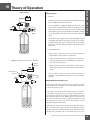
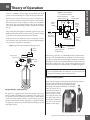
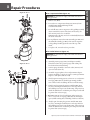
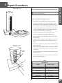
Spirit 300, 600 & 1200 Technical Service Manual I Preface Spirit 300, 600 & 1200 SERVICE MANUAL SPIRIT SERIES - 300, 600, 1200 CAIRE, Inc. 2200 Airport Industrial Dr., Ste. 500 Ball Ground, GA 30107 www.cairemedical.com Customer/Technical Service: United States Phone: 800 482 2473 Asia, Australia, Pacific Rim Phone: +61 297 494333 Fax: 888 932 2473 Europe Phone: Fax: +44(0) 1344 429224 +44 9(0) 1344 403100 Fax : 888 932 2473 Abbreviations LED Light Emitting Diode PRV Primary Relief Valve LOX Liquid Oxygen QDV Quick Disconnect Valve LPM Liters Per Minute RMA Return Materials Authorization NER Normal Evaporation Rate RP Repair Procedure OCD Oxygen Conserving Device R/R Removal and Replacement POI Patient Operating Instructions SRV Secondary Relief Valve Definition of Terms WARNING CAUTION NOTE (Item) Description of a condition that can result in personal injury or death. Description of a condition that can result in equipment or component damage. A statement containing information important enough to emphasize or repeat. Item numbers used throughout this manual are shown on the illustrations adjacent to the Repair Procedures. Disclaimer This manual covers use and maintenance of the Spirit series. This manual is intended for use by experienced personnel only. No attempt should be made to fill or maintain this equipment until both this manual and the Patient Operating Instruction booklet have been read and fully understood. Spirit 300, 600 & 1200 Technical Service Manual • PN 11805120 Rev F 1 II Table of Contents I.Preface................................................................................................................ 1 II. Table of Contents........................................................................................... 2 III. Equipment Description................................................................................ 3 IV.Specifications................................................................................................... 4 V.Safety.............................................................................................................. 5-9 VI. Theory of Operation............................................................................. 10-11 VII. Unpacking/Setup Instructions.................................................................12 Spirit 300, 600 & 1200 VIII.Operation........................................................................................................12 IX. Routine Maintenance.......................................................................... 13-14 X. Troubleshooting (Table of Contents)....................................................15 Troubleshooting Chart........................................................................ 16-21 Repair Procedures................................................................................ 22–31 Service Tools/Equipment/Supplies........................................................32 XI. Parts Price List................................................................................................33 Ordering Information..................................................................................34 XII. Return Policy..................................................................................................35 Spirit 300, 600 & 1200 Technical Service Manual • PN 11805120 Rev F 2 III Equipment Description Spirit 300, 600 & 1200 Figure 1: Spirit Unit CAIRE, Inc.’s Spirit units serve as the portable components of the CAIRE Reservoir/Spirit supplementary oxygen system. Enclosed in a durable leather-look case, Spirits incorporate a stainless steel cryogenic container with the valves, plumbing, and associated hardware required to deliver gaseous oxygen to the patient at near ambient temperature. 3. Case – The case is made of a durable leather-look material which houses and protects the cryogenic container, the breathing circuit, and the oxygen conserving device (OCD). The Spirit is comprised of six major assemblies. Grouped according to function, they are: 5. Filling Circuit – The filling circuit consists of a quick disconnect device (either side fill or top fill) and associated plumbing, allowing the Spirit unit to be easily filled from sources with a variety of connectors. 1. Cryogenic Container – This assembly is a double-walled, vacuum insulated dewar for storing liquid oxygen at approximately -183° Celsius. 2. Breathing Circuit – This circuit consists of the manifold assembly and a breathing coil. It utilizes liquid oxygen from the cryogenic container and warms it to near ambient temperature, so oxygen gas can be delivered to the patient. 4. Spring Scale – The spring scale uses a mechanical scale to display the liquid oxygen contents based on the weight of the unit. 6. Oxygen Conserving Device – This assembly uses a pressure transducer to detect negative pressure created when a patient inhales. A set volume of oxygen gas is then delivered to the patient cannula tube via an electronically controlled valve. NOTE: The oxygen conserving device (OCD) is unique to CAIRE, Inc. with US Patent No. 6,910,482. Spirit 300, 600 & 1200 Technical Service Manual • PN 11805120 Rev F 3 IV 1 Specifications (Nominal Values) Spirit 300 Capacity LOX, mass lbs (kg): LOX, volume L: O2, volume L: 0.79 (0,36) 1.50 (0,68) 3.00 (1,36) 0,330,66 1,25 275516 1087 Selectable Flow Rates Liters per minute: Spirit 600 Off, 1, 1.5, 2, 3, 4, 5, CF CF = Continuous Flow @ 2LPM Pulse Flow Delivery ~(15 ml) x (LPM setting) per breath Normal Evaporation Rate: Pounds per day (Kg per day): 1.2 (0,54) Operating Pressure PSIG (Bar): 20 ± 2 (1,4± 0,14) Primary Relief Valve Setting PSIG (Bar): 24.5-25.5 (1,7 - 1,8) Secondary Relief Valve Setting PSIG (Bar): 27.0-33.0 (1,9-2,3) Height Inches (mm): 8.8 (223) Width Inches (mm): Weight Empty lbs (kg): Full lbs (kg): 3.5 (1,6) 4.3 (1,95) Spirit 1200 11.5 (292) Spirit 300, 600 & 1200 14.0 (356) D-Shaped: 6.0 x 4.5 (152 x 114) 4.1 (1,86) 5.6 (2,54) 5.0 (2,27) 8.1 (3,68) Fill Connector Types Male side mounted rotary coupling or female bottom mounted push or coupling, or bottom mounted rotary coupling. Power Source 2 C-Cell Batteries Battery Life 500 Hours (approximate) Alarms/Indicators Green LED with every breath Red LED for low battery with every breath Spirit 300, 600 & 1200 Technical Service Manual • PN 11805120 Rev F 4 V Safety These hazards require certain safety precautions to be taken when working with or around gaseous and/or liquid oxygen: 1. Never permit combustible substances such as greases, oils, solvents, or other compounds not oxygen compatible to contact any component of the unit exposed to higher-thanatmospheric concentrations of gaseous or liquid oxygen. This especially applies to tubing, fittings, and valves. 2. Keep oxygen equipment away from open flames or electrical appliances such as heaters, stoves, toasters, and other devices with heating elements. 3. Never permit smoking in an area where oxygen equipment is repaired, filled, or used. 4. Always wear goggles, a face shield, and insulated gloves when working with or around liquid oxygen. While CAIRE, Inc. equipment is designed and built to the most rigid standards, no piece of mechanical equipment can ever be made 100% foolproof. Strict compliance with proper safety practices is necessary when using any Spirit unit. We recommend that our distributors emphasize safety and safe handling practices to their employees and customers. While safety features have been designed into the unit and safe operations are anticipated, it is necessary that all distributor personnel carefully read and fully understand WARNINGS, CAUTIONS, and NOTES throughout the manual. Periodic review of this information is recommended. WARNING: Excess accumulation of oxygen creates an oxygenenriched atmosphere (defined by the Compressed Gas Association as an oxygen concentration above 23%). In an oxygen-enriched atmosphere, flammable items may burn vigorously and may explode. Certain items considered non-combustible in air may burn rapidly in such an environment. Keep all organic materials and other flammable substances away from possible contact with oxygen; particularly oil, grease, kerosene, cloth, wood, paint, tar, coal dust, and dirt which may contain oil or grease. DO NOT permit smoking or open flame in any area where oxygen is stored, handled, or used. Failure to comply with this warning may result in serious personal injury. Spirit 300, 600 & 1200 Oxygen, as it exists at standard atmospheric pressure and temperature, is a colorless, odorless, and tasteless gas. Oxygen constitutes 21% of the atmosphere, by volume. Aside from its well-documented ability to sustain life, oxygen also supports combustion, even though it is nonflammable. Many substances which will burn in air, burn at a faster rate and at a higher temperature in an oxygen enriched atmosphere. Other materials that do not burn in air will burn as oxygen concentration increases. Additionally, many greases and liquid solvents become extremely hazardous materials when placed in an oxygen-enriched environment. In its liquid form, oxygen is still odorless and tasteless, but is pale blue in color. At an operating pressure of 1,4 bar (20 psig), the temperature of liquid oxygen is about -173°C (-280° F). Skin exposed to such a low temperature can become severely frostbitten. WARNING: In the event a unit is dropped, tipped over, or unreasonably abused, immediately, but cautiously, raise the container to its normal vertical position. If substantial container damage has occurred, remove the liquid oxygen from the vessel in a safe manner (RP10). Purge the unit with an inert gas (nitrogen) and promptly return it to CAIRE for inspection. The container should be prominently marked “CONTAINER DROPPED, INSPECT FOR DAMAGE.” Failure to comply with these procedures may result in personal injury and can seriously damage the container. WARNING: Personnel must remove liquid oxygen and depressurize the unit before removing parts or loosening fittings from a unit. Failure to do so may result in personal injury from the extreme cold of liquid oxygen and/or the pressure in the vessel. WARNING: During transfer of liquid oxygen, components will become extremely cold. Care should be used to avoid any contact with these components, as serious frostbite may result. WARNING: Keep filled unit upright at all times. Tip over of filled unit may result in liquid oxygen leakage and/or an oxygenenriched atmosphere. WARNING: Only use replacement equipment which is compatible with liquid oxygen and has been cleaned for oxygen use. Do not use regulators, fittings, hoses, etc. which have been previously used in non-oxygen service. Spirit 300, 600 & 1200 Technical Service Manual • PN 11805120 Rev F 5 V 1 Safety WARNING: The use of Accessories, transducers, and cables other than those specified by the manufacturer may result in increased Emissions or decreased immunity of the SPIRIT. WARNING: Portable and mobile RF communications equipment can affect Medical Electrical Equipment. WARNING: The SPIRIT should not be used adjacent to or stacked with other equipment, and that if adjacent or stacked use is necessary, the SPIRIT should be observed to verify normal operation in the configuration in which it will be used. Table 1 Spirit 300, 600 & 1200 WARNING: Medical electrical Equipment needs special precautions regarding EMC and needs to be installed and put into service according to the EMC information provided in this manual. Guidance and Manufacturer’s declaration—electromagnetic emissions The SPIRIT is intended for use in the electromagnetic environment specified below. The customer or the user of the SPIRIT should assure that it is used in such an environment. Emissions test Compliance RF emissions CISPR 11 Group 1 Electromagnetic environment—guidance The SPIRIT uses RF energy only for internal function. Therefore, its RF emissions are very low and are not likely to cause any interference in nearby electronic equipment. RF emissions CISPR 11 Harmonic emissions The SPIRIT is suitable for use in all establishments, including IEC 61000-3-2 domestic establishments and those directly connected to the public Voltage fluctuations/ low-voltage power supply network that supplies buildings used for flicker emissions domestic purposes. IEC 61000-3-3 Class B Not applicable Not applicable Spirit 300, 600 & 1200 Technical Service Manual • PN 11805120 Rev F 6 V 1 Safety Guidance and manufacturers declaration—electromagnetic immunity The SPIRIT is intended for use in the electromagnetic environment specified below. The customer or the user of the SPIRIT should assure that it is used in such an environment. Immunity test Electrostatic discharge (ESD) IEC 60601 test level Compliance level ±6 kV contact ±6 kV contact ±8 kV air ±8 kV air Electromagnetic environment—guidance Floors should be wood, concrete or ceramic tile. If floors are covered with synthetic material, the relative IEC 61000-4-2 humidity should be at least 30%.* Electrical fast ±2 kV for power Not applicable Not applicable transient/burst supply lines DC powered device IEC 610004-4 Surge IEC 61000-4-5 ±1 kV for Not applicable input/output linesNo data input/output lines ±1 kV line(s) to line(s) Not Applicable ±2 kV line(s) DC powered device <5% UT (>95% dip short interruptions in UT) for 0,5 cycle and voltage 40% UT (60% dip variations on in UT) for 5 cycles Not Applicable power supply 70% UT (30% dip DC powered device input lines in UT) for 25 cycles IEC 61000-4-11 <5% UT (>95% dip Power frequency (50/60 Hz) magnetic field Not Applicable to earth Voltage dips, Spirit 300, 600 & 1200 Table 2 Not Applicable in UT) for 5 sec 3 A/m 3 A/m Power frequency magnetic fields should be at levels characteristic of a typical location in a typical commercial or hospital environment. IEC 61000-4-8 Note: UT is the a.c. mains voltage prior to application of the test level. * This statement indicates that the required testing was performed in a controlled environment and the SPIRITS are found to be compliant with regulations. Spirit 300, 600 & 1200 Technical Service Manual • PN 11805120 Rev F 7 V Safety Guidance and manufacturers declaration—electromagnetic immunity The SPIRIT is intended for use in the electromagnetic environment specified below. The customer or the user of the SPIRIT should assure that it is used in such an environment. Immunity test IEC 60601 test level Compliance level Conducted RF 3Vrms Not Applicable IEC 61000-4-6 150kHz to 80 MHz Battery powered device Radiated RF 3 V/m 3 V/m IEC 61000-4-3 80 MHz to 2,5 GHz Electromagnetic environment—guidance Portable and mobile RF communications equipment should be used no closer to any part of the SPIRIT, including cables, than the recommended separation distance calculated from the equation applicable to the frequency of the transmitter. Recommended separation distance d = 1.2 √P d = 1.2 √P 80 MHz to 800 MHz d = 2.3 √P 800 MHz to 2,5 GHz Field strengths from fixed RF transmitters, as determined by an electromagnetic site surverya, should be less than the compliance level in each frequency rangeb. Interference may occur in the vicinity of equipment marked with the following symbol: Spirit 300, 600 & 1200 Table 4* where P is the maximum output power rating of the transmitter in watts (W) according to the transmitter manufacturer and d is the recommended separation distance in meters (m). NOTE 1 At 80 MHz and 800 MHz, the higher frequency range applies. NOTE 2 These guidelines may not apply in all situations. Electromagnetic propagation is affected by absorption and reflection from structures, objects and people. a Field strengths from fixed transmitters, such as base stations for radio (cellular/cordless) telephones and land mobile radios, amateur radio, AM and FM radio broadcast and TV broadcast cannot be predicted theoretically with accuracy. To asses the electromagnetic environment due to fixed RF transmitters, an electromagnetic site survey should be considered. If the measured field strength in the location in which the SPIRIT is used exceeds the applicable RF compliance level above, the SPIRIT should be observed to verify normal operation. If abnormal performance is observed, additional measures may be necessary, such as reorienting or relocating the SPIRIT. b Over the frequency range 150 kHz to 80 MHz, field strengths should be less than 3 V/m. * This table is included as a standard requirement for equipment which has been tested to specific test levels and over specific frquency ranges and been found compliant with regulations. Spirit 300, 600 & 1200 Technical Service Manual • PN 11805120 Rev F 8 V 1 Safety Recommended separation distances between portable and mobile RF communications equipment and the SPIRIT The SPIRIT is intended for use in an electromagnetic environment in which radiated RF disturbances are controlled. The customer or the user of the SPIRIT can help prevent electromagnetic interference by maintaining a minimum distance between portable and mobile RF communications equipment (transmitters) and the SPIRIT as recommended below, according to the maximum output power of the communications equipment. Rated maximum outputSeparation distance according to frequency of transmitter power of transmitter m 150 kHz to 80 MHz 80 MHz and 800 MHz 800 MHz to 2,5 GHz d=1.2√P d=1.2 √P d=2.3 √P 0,01 0.12 m 0.12 m 0.23 m 0,1 0.38 m 0.38 m 0.73 m 1 1.2 m 1.2 m 2.3 m 10 3.8 m 3.8 m 7.3 m W Spirit 300, 600 & 1200 Table 6* 100 12 m 12 m 23 m For transmitters rated at a maximum output power not listed above, the recommended separation distance (d) in meters (m) can be estimated using the equation applicable to the frequency of the transmitter, where P is the maximum output power rating of the transmitter in watts (W) according to the transmitter manufacturer. NOTE 1 at 80 MHz and 800 MHz, the separation distance for the higher frequency range applies. NOTE 2 These guidelines may not apply in all situations. Electromagnetic propagation is affected by absorption and reflection from structures, objects and people. * This table is included as a standard requirement for equipment which has been tested to specific test levels and over specific frquency ranges and been found compliant with regulations. Spirit 300, 600 & 1200 Technical Service Manual • PN 11805120 Rev F 9 VI Theory of Operation Filling (Figure 2) 1.Method OCD The Spirit is a portable unit designed to be filled by the patient from a CAIRE-manufactured reservoir. Liquid Gas Vent Valve The unit is filled by coupling the quick disconnect valve of the Spirit with the quick disconnect valve on the Reservoir and opening the vent valve on the Spirit. A pressure differential causes liquid oxygen to flow up the Reservoir fill tube, through the coupled quick connectors, and into the inner vessel of the Spirit. There will be some oxygen vaporized during filling. This gas is discharged through the vent valve. The unit can be considered full when liquid oxygen is expelled from the vent valve. Closing the vent valve and separating the units terminates the fill process. Fill Connection (QDV) Gas Spirit 300, 600 & 1200 Figure 2: Filling 2. Saturation Pressure Figure 3: Operation Pressure Above 20 PSIG Gas to Patient OCD Economizer (Open) Warming Coils Liquid oxygen saturation pressure can seriously affect the overall efficiency and operation of a Spirit unit. a.If the saturation pressure of the liquid in the fill source is greater than 30 psig (2,1 bar), high filling losses and/or frozen relief valves may result. b.If the saturation pressure of the liquid in the fill source is lower than 18 psig (1,2 bar), below tolerance flow rates may result. These problems can be prevented by always ensuring the Reservoir is properly filled according to its respective service manual. Oxygen Withdrawal (Figures 3, 4) Gas With oxygen in the unit, and the vent valve closed, the pressure in the inner vessel will remain at or near the primary relief valve pressure of 25 psig (1,7 bar). In the Spirit, as in all vacuum-insulated cryogenic containers, some liquid (oxygen in this case) is always evaporating into a gas. The rate of generation of this gas (called head gas) is called the normal evaporation rate (NER). When the flow selection knob is in the off position, this gas will build up pressure until it is released between 21.9 psig (1,5 bar) and 24.2 psig (1,7 bar) through the primary relief valve. When the flow selection knob is at any setting other than off, and the economizer valve is open (pressure above 20 psig [1,4 bar]), gaseous oxygen is forced from the head space in the inner vessel, through the economizer valve, to the OCD. This process conSpirit 300, 600 & 1200 Technical Service Manual • PN 11805120 Rev F 10 VI Theory of Operation Whenever gas is removed from the space above the liquid oxygen, the inner vessel internal pressure begins to drop slightly. When the pressure drops to 20 psig (1,4 bar), the economizer valve closes. This causes liquid oxygen to flow up the withdraw tube and through the warming coil where it expands and warms into gas. The gas then flows through the economizer regulator body to the OCD assembly where its flow is metered to the patient according to the flow selection knob setting and patient demand. As the pressure in the container increases over 20 psig (1,4 bar), the economizer valve opens and the cycle repeats, maintaining the correct gaseous oxygen flow to the patient. Figure 4: Operation Pressure Below 20 psig (1,4 bar) Gas to Patient OCD Economizer (Closed) Warming Coils Pressure Transducer ( Vacuum Sensor ) OCD Circuit Board Needle Valve 9 LPM Barbed Oxygen Outlet Oxygen Inlet -from Economizer Bleed Orifice ( to Atmosphere ) PIN / Poppet Valve (Only Open in CF Knob Position) Spirit 300, 600 & 1200 Figure 5: OCD Schematic U.S. Patent # 6,910,482 serves or “economizes” liquid oxygen by withdrawing the head gas first, instead of allowing it to escape through the relief valve. Solenoid Valve ( 3 Way ) Fixed Orifice 2 LPM Flow The OCD is powered by 2 C-cell alkaline batteries. When battery voltage is low, the LED indicator will blink red with every triggered pulse. The batteries should be replaced with new ones when this happens. In the event of OCD malfunction, the flow selection knob can be turned to the “CF” position. This setting bypasses all electronics and delivers a continuous flow of 2 LPM to the patient. CAUTION: For proper OCD function, a standard cannula should be used. Its length should be less than 25 ft. (7,6 m) and it should be designed for 6 LPM or greater continuous flow. Liquid Level Measurement Liquid Oxygen Delivery – OCD (Figure 5) All Spirits are equipped with electronic Oxygen Conserving Devices (OCD). The OCD pressure transducer detects the negative pressure generated when the patient begins to inhale. Based on the flow selection knob position, a solenoid valve is open for a predetermined length of time, dispensing a controlled volume of oxygen gas to the patient. An LED indicator blinks green with each triggered pulse. Spirit units are equipped with spring scales for liquid level measurement. This system measures the level of liquid oxygen inside the unit using a mechanical spring. The spring scale display is calibrated to read empty when an empty unit is suspended by its ring. As liquid oxygen is transferred into the portable, the weight increases and the spring scale reflects the increase. Calibration can only be performed while the unit is empty. Spirit 300, 600 & 1200 Technical Service Manual • PN 11805120 Rev F 11 VII Unpacking and Setup Setup 1. Always inspect carton for shipping damage. Report any damage to freight company before signing a bill of lading. 1. Verify 2 new C-cell alkaline batteries are properly installed within the battery compartment. 2. Check description marked on carton against your order. 2. Verify the unit has appropriate warning/caution label, along with the Patient Operating Instructions Manual (POI). 3. Unpack unit, including Patient Operating Instructions (POI). 4. Set aside packing materials in case the unit must be returned to the factory. 3. If not attached, assemble the Shoulder Strap and Spring Scale assembly to unit and verify proper functionality. 4. Connect a standard cannula to the unit. The cannula should be rated at at least 6 LPM for continuous flow and should be less than 25 ft. (7.6 m) in length. Spirit 300, 600 & 1200 Unpacking VIII Operation Refer to Patient Operating Instructions Manual (POI). Spirit 300, 600 & 1200 Technical Service Manual • PN 11805120 Rev F 12 IX Routine Maintenance (Schedule A, Biennial) Schedule A – Biennial A. Introduction Routine maintenance is a series of steps used to assure that equipment is functioning properly. 1. If a unit fails a given test, one of two things may be done. a. Refer to Troubleshooting/Repair (Section X) of this manual. b. Return unit to CAIRE, Inc. for repair. 2. Schedule A – Maximum of two years between routine maintenance testing. Unit should be tested when a problem is suspected. B. Procedure Follow the steps in order listed. If the unit fails any step, refer to Troubleshooting/Repair (Section X) of this manual. 1. Visual Inspection: a. Look for damaged or missing parts. b. Dry condensation pad for Spirit 1200. Replace if soiled. 2. Fill Unit: a. Fill unit full of LOX. b. Check for audible or visual leaks in QDV and vent valve. c. Verify that spring scale reads full. 3. Check Efficiency of Unit: a. Allow unit to sit after fill for 10–15 minutes. b. Inspect bottle for cold sweaty condition and for excessive venting from relief valve (some venting is normal). c. If either condition is observed, conduct NER test (see RP26 in this manual). 4. Flow Test (Table 1): a. Set flow selection knob to “CF”, run for at least 20 minutes. b.Check all flow settings with the chart below (RP22)and check pressure is within a range of 18–22 psig (1,2–1,5 bar). Spirit 300, 600 & 1200 There are two schedules for routine maintenance which the home health care distributor may follow. These schedules allow the distributor maximum flexibility while assuring that equipment is operating properly. Table 1 Spirit Flow Test Setting Volume or LPM OFF -0 1 LPM (Pulse) 12 to 18 mL 1.5 LPM (Pulse) 18 to 26 mL 2 LPM (Pulse) 26 to 34 mL 3 LPM (Pulse) 40 to 50 mL 4 LPM (Pulse) 54 to 66 mL 5 LPM (Pulse) 67 to 83 mL CF (Continuous) 1,70 to 2,30 LPM 5. Prepare for Use: a. Empty contents by turning flow selection knob to “CF” and running unit until dry and warm to room temperature (may take up to 8 hours). b. Verify that scale reads empty and that LED indicator blinks green when triggered. c. Clean case per RP25. Spirit 300, 600 & 1200 Technical Service Manual • PN 11805120 Rev F 13 IX Routine Maintenance (Schedule B, Continuous) A. Introduction Continuous maintenance is a set of tests and inspections performed consistently to ensure equipment is functioning properly. It can be done with equipment in service by drivers or other personnel. 1. If a unit fails a given test, it should be taken out of service and sent to the Repair Center/Department for further inspection. 2. Schedule B – Checks are made when the driver visits patients and when equipment is transferred between patients. B. Procedure These inspections are to be performed by driver or other personnel when Spirit is in use by the patient (LOX in the unit). This procedure must be performed at least once per year. 1. Visual Inspection: a. Case not damaged or dirty. Flow control knob turns easily with firm detent feel. b.Condensation pad on Spirit 1200 is not soaking wet or excessively dirty. c. QDV pin not bent (male rotary QDVs). 2. Verify that scale reads correct liquid level. 3. Check CF flow rate. Erie liter meter (± 0.25 LPM) can be used. 4. Flow Test (Table 2): a. Set flow control knob to “CF”, run for at least 20 minutes. b. Check all flow settings with chart below (RP22) and check pressure is within a range of 18-22 psig (1,2–1,5 bar). Table 2 Spirit Flow Test Setting Volume or LPM OFF -0 1 LPM (Pulse) 12 to 18 mL 1.5 LPM (Pulse) 18 to 26 mL 2 LPM (Pulse) 26 to 34 mL 3 LPM (Pulse) 40 to 50 mL 4 LPM (Pulse) 54 to 66 mL 5 LPM (Pulse) 67 to 83 mL CF (Continuous) 1.70 to 2.30 LPM Spirit 300, 600 & 1200 Schedule B – Continuous 5. Prepare for Use: a. Empty contents by turning flow selection knob to “CF” and running unit until dry and warm to room temperature (approximately two hours). b. Verify that scale reads empty and that LED indicator blinks green when triggered. c. Clean case per RP25. These inspections/tests are to be done between patients. 1. Visual Inspection: a. Broken case. b. Condense pad (replace if soiled). c. QDV pin not bent (male rotary QDVs). d.Inspect interior of unit for dirt or contaminants. 2. Verify that liquid level measurement reads empty. 3. Fill Unit: a. Verify that liquid level measurement reads full (FULL green stripe). b. Check for audible/visual leaks in QDV and vent valves. Spirit 300, 600 & 1200 Technical Service Manual • PN 11805120 Rev F 14 X 1 Troubleshooting/Repair Procedures A.Introduction……………………………………………………………………… 15 B. Troubleshooting Charts………………………………………………… 16–21 C. Repair Procedures RP1 General…………………………………………………………… 22 RP2 Battery R/R ……………………………………………………… 23 RP3 Condensate Pad R/R…………………………………………… 23 RP4 Soft Feature Case R/R …………………………………………… 23 RP5 Spring Scale Liquid Level Calibration…………………………… 23 RP6 OCD Assembly R/R……………………………………………… 24 RP7 Manifold Assembly R/R………………………………………… 24 RP8 Clean/Dry Dewar………………………………………………… 24 RP9 LOX Fill………………………………………………………… 24 RP10 Empty and Warm ……………………………………………… 25 RP11 QDV R/R: Side Fill……………………………………………… 25 RP12 QDV and Lip Seal R/R: Bottom Fill…………………………… 25 RP13 Pressure Retention Test ………………………………………… 26 RP14 Plumbing Leak Test……………………………………………… 26 RP15 Vent Valve R/R ………………………………………………… 27 RP16 SRV R/R………………………………………………………… 27 RP17 PRV R/R ………………………………………………………… 27 RP18 Vaporizer Coil R/R……………………………………………… 28 RP19 Relief Valve Test………………………………………………… 28 RP20 Operating Pressure Test………………………………………… 29 RP21 Economizer Regulator R/R ……………………………………… 29 RP22 Economizer Regulator Adjustment R/R………………………… 30 RP23 Pulse Volume Test ……………………………………………… 30 RP24 CF Flow Rate Test……………………………………………… 31 RP25 Case Cleaning…………………………………………………… 31 RP26 NER Test………………………………………………………… 31 D. Service Tools/Equipment/Supplies……………………………………………… 32 Spirit 300, 600 & 1200 Table of Contents Introduction 1. These procedures are designed to be performed only by qualified personnel with proper equipment. 2. Any failure during routine maintenance checks will refer you to this section. See Troubleshooting Chart for appropriate procedure. Spirit 300, 600 & 1200 Technical Service Manual • PN 11805120 Rev F 15 X 1 Troubleshooting Chart Probable Cause Unable to start fill or ex- a) cessively long fill times Corrective Action QDV not properly engaged on the reservoir Make sure the QDV on the portable and reservoir are properly aligned and ensure that a downward force is being applied to the portable. b) Reservoir is empty Swap or re-fill the reservoir c) Vent valve not open Ensure that the vent valve lever is fully in the open position. The lever must be open to begin a fill. d) FCV is open Be sure that the FCV knob is in the off (“0”) position. If the valve is open, fill times can increase. e) Reservoir saturation pressure is too low Swap reservoirs or allow the reservoir time to stabilize and build pressure f) Vent valve is obstructed Inspect the vent tubes for blockages. Clean by blowing out with compressed gas or replace parts if necessary. g) Leak in the system Check the portable for leaks (RP14) and repair if needed. h) QDV damaged or faulty Inspect the QDV and be sure the poppet opens properly and smoothly. If necessary, replace the QDV cartridge or the entire QDV (RP11 & RP12) i) Faulty vent valve Replace the vent valve (RP15) 2) Liquid leaks from the coupled QDVs during the fill a) Worn or damaged lip seal Replace the QDV lip seal (RP12) 3) Unable to disconnect the portable from the reservoir a) Pop-off assembly not being utilized Ensure that the pop-off assembly on the reservoir is being used. Do not use force to separate the QDVs. b) QDVs are frozen together Leave the units coupled with the vent valve closed and let them sit until they warm up enough to disconnect. Always ensure that male and female QDV’s are cleaned and dried prior to each fill. Ice crystal preventing the QDV from closing properly. Engage and disengage the portable onto the reservoir several times to dislodge the ice crystal. Always be sure that the male and female QDVs are wiped clean and dry before filling. b) Dirty or damaged QDV poppet Replace the QDV cartridge or the entire QDV assembly (RP11 & RP12) a) Vent valve is not fully closed Ensure that the vent valve lever is fully in the closed position. b) The portable has been transported or laid in an improper operating position Return the portable to an upright or acceptable operating position and allow several minutes for stabilization. c) Vent valve is frozen open Allow the portable to warm until the vent valve can close. After the warm up, allow up to 60 minutes for the portable to stabilize and build pressure before operating. d) Faulty vent valve Replace the vent valve (RP15) 4) 5) Liquid leaks from the a) QDV poppet after filling Liquid leaks from the vent valve tube/outlet Spirit 300, 600 & 1200 Technical Service Manual • PN 11805120 Rev F Spirit 300, 600 & 1200 Symptom 1) 16 X Troubleshooting Chart 7) 8) Excessive venting from relief valves (hissing sound) No Flow Low flow at all LPM settings Probable Cause Corrective Action a) The portable has been transported or laid in an improper operating position Return the portable to an upright or acceptable operating position and allow several minutes for stabilization. b) Saturation pressure too high. Inspect the saturation pressure of the reservoir used for filling. Allow at least 30 minutes at no flow for the portable to saturate properly. c) Relief valve frozen open Allow the portable to warm and thaw. Attempt to re-fill the portable. d) Faulty relief valve Test the relief valve (RP19) and replace if necessary (RP16 & RP17) e) Partial or complete loss of vacuum Conduct the NER test (RP26) and return the unit to CAIRE, inc. if necessary. a) Portable is empty Check the contents indicator/level gauge and fill the portable if needed. b) Flow control valve turned off Ensure the flow control knob is not in the off (“0”) position. c) Nasal cannula kinked or Ensure proper nasal cannula functionality and positioning disconnected e) Saturation pressure is too low Inspect the saturation pressure of the reservoir used for filling. Allow at least 30 minutes at no flow for the portable to saturate properly. f) Leak in the system Perform a leak check on the plumbing (RP14). Repair leaks as necessary. g) Relief valve is open Ensure that there is no venting from the relief valves. If there is refer to the corrective actions for “Excessive venting from relief valves (hissing sound)” h) Vent valve is open Ensure that there is no venting from the vent valve outlet/tube. If there is refer to the corrective actions for “Liquid leaks from the vent valve tube/outlet” i) Blockage in the liquid withdrawal circuit Check the warming coils and withdrawal tubes for blockages. Replace if necessary. j) OCD Faulty Replace the OCD (RP6) a) Nasal cannula kinked or Inspect the functionality of the nasal cannula. leaking b) Saturation pressure is too low Inspect the saturation pressure of the reservoir used for filling. Allow at least 30 minutes at no flow for the portable to saturate properly. c) Leak in the system Perform a leak check on the plumbing (RP14). Repair leaks as necessary. d) Economizer valve faulty Test the economizer (RP21) and replace if necessary. e) Blockage in the liquid withdrawal circuit Check the warming coils and withdrawal tubes for blockages. Replace if necessary. f) OCD faulty Replace the OCD (RP6) Spirit 300, 600 & 1200 Technical Service Manual • PN 11805120 Rev F Spirit 300, 600 & 1200 Symptom 6) 17 X Troubleshooting Chart Unit stops pulsing in demand mode 10) Flow stops suddenly on continuous setting NOTE: For continuous flow to continue a inhalation must be detected periodically. Refer to the Theory of Operation section of this manual for more information. 11) Unit flows continuously on demand settings 12) Increased NER Probable Cause Corrective Action a) Cannula is disconnected Ensure the nasal cannula is firmly attached to the barb(s). b) Cannula is blocked or kinked Inspect the cannula for kinks, bends, or water droplets. Replace the cannula if necessary. c) Cannula tips not positioned properly in the nose Ensure the cannula remains in the nostrils and do not slide to one side. d) Patient is breathing with Patient must inhale through their nose to initiate pulse/demand flow. their mouth open. e) Saturation pressure is out of specification Reference symptom 14). Inspect the saturation pressure of the reservoir used for filling. Allow at least 30 minutes at no flow for the portable to saturate properly. f) Leak in the system Perform a leak check on the plumbing (RP14). Repair leaks as necessary. g) Faulty OCD Test the OCD (RP6) and replace if necessary. a) Cannula is disconnected Ensure the nasal cannula is firmly attached to the barb(s). b) Cannula is blocked or kinked Inspect the cannula for kinks, bends, or water droplets. Replace the cannula if necessary. c) Cannula tips not positioned properly in the nose Ensure the cannula remains in the nostrils and do not slide to one side. d) Patient is breathing with Patient must inhale through their nose to initiate continuous flow. their mouth open. e) Saturation pressure is out of specification Reference symptom 14). Inspect the saturation pressure of the reservoir used for filling. Allow at least 30 minutes at no flow for the portable to saturate properly. f) Faulty OCD Test the OCD (RP6) and replace if necessary. a) Saturation Pressure is too high Inspect the saturation pressure of the reservoir used for filling. Allow at least 30 minutes at no flow for the portable to saturate properly. b) Faulty OCD Test the OCD (RP6) and replace if necessary. a) Saturation Pressure is too high Inspect the saturation pressure of the reservoir used for filling. Allow at least 30 minutes at no flow for the portable to saturate properly. b) Leak in the system Perform a leak check on the plumbing (RP14). Repair leaks as necessary. c) Relief valve open Ensure that there is no venting from the relief valves. If there is refer to the corrective actions for “Excessive venting from relief valves (hissing sound)” d) Partial or complete loss of vacuum Conduct the NER test (RP26) and return the unit to CAIRE, inc. if necessary. Spirit 300, 600 & 1200 Technical Service Manual • PN 11805120 Rev F Spirit 300, 600 & 1200 Symptom 9) 18 X Troubleshooting Chart Probable Cause Corrective Action Frost is acceptable Some frost on the outer case and on the plumbing is acceptable, especially at high flow rates during continuous use. This is due to the evaporation of LOX to gas and the temperature difference between the LOX and room temperature. High humidity level High humidity levels can increase frost accumulation. Saturation pressure is too high Inspect the saturation pressure of the reservoir used for filling. Allow at least 30 minutes at no flow for the portable to saturate properly. d) Leak in the system Perform a leak check on the plumbing (RP14). Repair leaks as necessary. e) Relief valve open Ensure that there is no venting from the relief valves. If there is refer to the corrective actions for “Excessive venting from relief valves (hissing sound)” f) Partial or complete loss of vacuum Conduct the NER test (RP26) and return the unit to CAIRE, inc. if necessary. a) Saturation pressure is out of specification Inspect the saturation pressure of the reservoir used for filling. Allow at least 30 minutes at no flow for the portable to saturate properly. b) Leak in the system Perform a leak check on the plumbing (RP14). Repair leaks as necessary. c) Economizer valve faulty Test the economizer (RP21) and replace if necessary. a) Saturation pressure is out of specification Inspect the saturation pressure of the reservoir used for filling. Allow at least 30 minutes at no flow for the portable to saturate properly. b) Leak in the system Perform a leak check on the plumbing (RP14). Repair leaks as necessary. c) PRV faulty Test the PRV (RP19) and replace (RP17) if necessary. 14) Unit will not maintain acceptable pressure when in use 15) Unit will not maintain acceptable pressure in standby mode Spirit 300, 600 & 1200 Technical Service Manual • PN 11805120 Rev F Spirit 300, 600 & 1200 Symptom 13) Excessive Frost a) NOTE: Minimal frost on the case and on the plumbing is normal. This symptom applies b) to frost that is much c) greater than what is normally observed. 19 X Troubleshooting Chart Case Case Visual Visual Bad Bad Replace Replace Defective Defective Part Part Ok Ok QDV QDV Pin Pin Bad Bad Replace QDV Replace Poppet QDV No No Yes Yes Scale Reads Scale Reads Empty Empty Fill Fill No No QDV QDV QDV LeaksQDV During Leaks After Leaks During Leaks Fill Fill After Fill Fill No No Vent Vent Leaks Leaks Yes Yes Scale Reads Scale FullReads Full No No Yes Yes Yes Yes Yes Yes No No Calibrate Calibrate Scale Scale Empty & Replace Warm Liberator Dewar Lip Seal Empty & Empty Warm & Warm Dewar Dewar Empty & Empty Warm & Warm Dewar Dewar Calibrate Calibrate Scale Scale Fill Fill Replace Replace Vent Valve Vent Valve Place on Place on Test Scale Test Scale Let Sit Let Sit 5 Hours 16-18 Hours Spirit 300, 600 & 1200 Good Good QDV QDV Leaks After Leaks Fill After No Fill No Yes Yes Empty & Empty Warm & Warm Dewar Dewar Spirit 300, 600 & 1200 Technical Service Manual • PN 11805120 Rev F 20 Pass Pass Yes Yes Test OCD Flow Test Flows Setting Test Scale Test Scale Indicates >= Indicates 0.4 lbs >= 7.5 lbs Fail Fail No No Pressure Pressure Retention Retention Test Test Fail Fail Pass Pass Plumbing Plumbing Leak Test Leak Test Test Test Operating Operating Pressure Pressure Pass Pass Fail Fail Calibrate Calibrate Test Scale Test Scale Fail Fail Refill Refill Repair Repair Leak Leak Let Sit Let Sit 5 Hours 16-18 Hours Yes Yes Test Scale Test Scale Indicates >= Indicates >= 0.4 lbs 7.5 lbs No No Replace Replace Dewar Dewar Empty & Empty Warm & Warm Dewar Dewar Clean Clean Case Case File File Records Records Return Return Unit Unit to Service to Service Pass Pass High High Low Low Empty & Empty & Warm Dewar Warm Dewar Plumbing Leak Test Empty & Empty & Warm Dewar Warm Dewar Empty & Empty & Warm Dewar Warm Dewar Reset / Replace Replace Economizer PRV Replace OCD & Empty Assembly Warm Dewar Spirit 300, 600 & 1200 t Sit s Hours X 1 Troubleshooting Chart Pass Return OCD to Replace CAIRE FCV Fail Fail Repair Repair Leak Leak Reset /Replace Replace Economizer PRV Pressure Pressure Retention Retention Test Test Pass Pass Fail Fail Refill Refill Wait 1/2 Wait 4 Hour Hours To Use Troubleshooting Chart: * Start at the upper left corner. * The top line shows the steps of routine maintenance. * Unless otherwise noted by the arrows, the flow through the chart is to the right or down. Spirit 300, 600 & 1200 Technical Service Manual • PN 11805120 Rev F 21 X Repair Procedures The following procedures have been carefully prepared to allow proper removal and replacement of defective components and should be used in conjunction with the Troubleshooting Chart and the tests in this section. WARNING: Make sure the unit is empty and vent valve is open before replacing any component, except case assembly components. WARNING: The worker’s hands, tools, and clothing should be free of all oils and greases. CAUTION: When replacing components, make sure the new part is oriented exactly the same as the original part prior to installation. CAUTION: Some components require a specific amount of torque when assembling. Follow torque requirements where specified. NOTE: All replacement parts that come in contact with LOX must be factory approved, cleaned for oxygen service, and stored in sealed plastic bags. The repair area must be clean and separate from other areas. Room air should be filtered, and as free from dust, soot, and other contaminants as possible. WARNING: Parts that are welded in place must not be replaced in the field. Should these parts fail, return complete assembly or sub-assembly to factory for repair. DO NOT use solder or silver solder to repair broken welds. NOTE: When replacing components with pipe/tapered threads, use Teflon® tape. Apply Teflon® tape as a sealant to threads near end of component, avoiding first thread.. WARNING: The manufacturers of fluorolubricant warn users not to allow fluorolubricant to contaminate tobacco products. Wash fluorolubricant from hands before smoking. NOTE: When assembling new compression fittings, tighten 3/16” tube nuts five flats after finger tight, and 1/4” tube nuts eight flats after finger tight. When reassembling previously used compression fittings, tighten nuts one to two flats after finger tight. Spirit 300, 600 & 1200 RP1 – General WARNING: Do not use glues, thread locking compounds or unapproved sealants on any repairs. Spirit 300, 600 & 1200 Technical Service Manual • PN 11805120 Rev F 22 X Repair Procedures a. Unzip soft feature case battery compartment access door. b. Remove the C-cell alkaline batteries (2). c. Install (2) new C-cell alkaline batteries, paying close attention to correct polarity orientation. d. Rezip compartment access door. RP3 – Condensate Pad R/R for Spirit 1200 Only (Figure 6) Spirit 300, 600 & 1200 Figure 6: RP 2, 3 & 4 RP2 – Battery R/R (Figure 6) a. Unzip soft feature case access door at bottom of unit. b. Remove condensate pad (Item 17) and wring out any absorbed moisture. Allow pad to dry completely or dispose (if pad will not be reused). c. Replace condensate pad and rezip access door. RP4 – Soft Feature Case R/R (Figure 6) a. Follow RP2 (steps a and b) to remove batteries. b. Disconnect battery holder connector from mating connector originating from OCD board. c. Unscrew the 3 screws on top of the case (Item 8). d. Remove flow control knob. e. Unzip vertical zipper along the back of the case as well as case access door at the bottom of the unit. f. Carefully remove unit from case. g. To replace, reverse the above steps. RP5 – Spring Scale Liquid Level Calibration (Figure 7) Figure 7: RP5 NOTE: Spring scale adjustments will only set the placement of the indicator and not the span (empty to full movement). The span adjustment is fixed by the design. a. Empty and warm portable unit (see RP10). b. Lift the portable by the ring (directly above the spring scale) and note the amount of deviation in the indicator. 0 0.5 Red Stripe FULL EMPTY FULL c. Use a phillips head screwdriver to adjust the internal spring scale calibration screw, which can be accessed at the base of the spring scale housing tube. d. Adjust the spring scale calibration screw until the empty red stripe indication shown. e. Fill unit with liquid oxygen. Verify FULL green stripe is shown. ADJUST Spirit 300, 600 & 1200 Technical Service Manual • PN 11805120 Rev F 23 X Repair Procedures e. For a top fill unit, loosen fill tube nut (Item 87) from manifold elbow. f. Loosen and remove the (4) manifold mount screws (Item 31). g. Remove manifold assembly (Item 33) by lifting straight up. h. To replace manifold assembly, reverse above procedure. RP8 – Clean/Dry Dewar NOTE: Apply a small amount of fluorolubricant to o-ring and manifold retaining screws before installing. Ensure proper seating of o-ring in dewar flange. Use cross tightening of screws to assure manifold is assembled flat to flange. Torque screws to 20–22 inch-lbs (230–250 N-cm). Spirit 300, 600 & 1200 Figure 8: RP 6 Figure 9: RP 7 RP6 – OCD Assembly R/R (Figure 8) WARNING: The unit must be empty and warm before starting this procedure. a. Follow RP4 to remove case. b. Disconnect clear economizer gas outlet tube (Item 45) from OCD Assembly. c. Loosen 3 OCD mount screws (Item 22). d. Loosen 2 hex screws located between OCD board and economizer. e. Maintain relative mount screw(s) and spacer(s) position, as OCD Assembly is removed from unit. f. Connect 3 #6-32 nuts to mount screws, below the bottom spacer, so the OCD remains assembled. g. To replace, reverse the above steps. RP7 – Manifold Assembly R/R (Figure 9) WARNING: The unit must be empty of liquid oxygen before attempting calibration. a. Follow RP4 to remove case. b. Follow RP6 to remove OCD assembly. c. Disconnect clear economizer gas inlet tube (Item 30) from the manifold gas withdraw barb fitting (Item 40). a. Remove manifold assembly (RP7). b. Invert dewar and blow out inside with clean, dry nitrogen gas until inside is clean and dry. c. Replace manifold assembly. RP9 – LOX Fill Refer to POI for proper fill procedure. NOTE: Filling source must contain a minimum of 3 liters of properly saturated LOX. d. Loosen vaporizer coil nuts (Item 38) from both the manifold LOX withdrawl fitting and the economizer LOX inlet. Spirit 300, 600 & 1200 Technical Service Manual • PN 11805120 Rev F 24 X Repair Procedures Spirit 300, 600 & 1200 Figure 10: RP 11 RP10 – Empty and Warm 37 a. Turn flow control knob to CF setting. b. Allow unit to sit for 24 hours before proceeding. RP11 – QDV R/R: Side Fill (Figure 10) A WARNING: The unit must be empty of liquid oxygen before starting procedure. a. Remove case (RP4). b. Loosen retaining nut (Item A). c. Remove QDV (Item 37). d. To replace QDV, reverse above procedure, aligning pin in the upright position. Apply flurolubricant to O-ring (Item 36). Torque retaining nut to 140-150 inch-lbs. (1500– 1700 N-cm). 36 e. Reassemble unit and return to case. RP12 – QDV and Lip Seal R/R: Bottom Fill (Figure 11) Figure 11: RP 12 WARNING: The unit must be empty of liquid oxygen before starting procedure. a. Remove case (RP4). 59 b. Loosen fill tube nut so fill tube can be disconnected from QDV. c. Remove QDV (Item 80) and replace, tightening Item 57 to 140-150 inch-lbs. (1500–1700 N-cm) and Item 58 to 300 inchlbs. (3300 N-cm). 83 d. Reassemble in the reverse order. 44 e. Replace lipseal by removing Item 65 and Item 64. Apply a thin film of fluorolubricant to new Item 64 and insert into QDV. Tighten Item 65 to 140-150 inch-lbs. (1500–1700 N-cm). 57 84 39 58 64 65 Spirit 300, 600 & 1200 Technical Service Manual • PN 11805120 Rev F 25 X Repair Procedures a. Assemble oxygen regulator, hose, and pneumatic adapter. Connect assembly to oxygen gas source. WARNING: The unit must be empty and warm before starting procedure. b. Assemble pressure gauge (Item J) and adapter assembly. Thread hose barb onto pressure gauge (use Teflon® tape). Push tubing onto hose barb and attach with clamp. a. Remove soft feature case (RP4). c. Connect gauge assembly (Item J) to vent tube outlet (Item 39) and open vent valve (Item 16). d. Connect the proper pneumatic adapter to QDV (Item 37) for side fill units or (Item 80) for bottom fill. e. Increase pressure to 19 psig (1,3 bar). f. Remove pneumatic adapter from QDV. b. Assemble oxygen regulator, hose, and pneumatic adapter. Connect assembly to oxygen gas source. c. Assemble pressure gauge and adapter assembly (Item J). Thread hose barb onto pressure gauge (use Teflon® tape). Push tubing onto hose barb and attach with clamp. Spirit 300, 600 & 1200 RP14 – Plumbing Leak Test (Figure 12) RP13 – Pressure Retention Test (Figure 12) d. Connect gauge assembly (Item J) to vent tube outlet (Item 39) and open vent valve (Item 16). e. Connect pneumatic adapter to QDV (Item 37) to side fill units of (Item 80) for bottom fill. g. Close vent valve. f Increase pressure to 19 psig (1,3 bar). h. Allow unit to sit undisturbed for 30 minutes. g. Leak test all connections, joints, and valves with leak test solution. Do not apply leak test solution to any part of OCD circuit board. i. Open vent valve. j. If pressure (Item J) is at or above 10 psig (0,7 bar), unit passes test. NOTE: PRV (Item 49) and SRV (Item 43) may leak slowly. Repair all other leaks first and retest for pressure retention before changing relief valves. h. Close vent valve. Remove pressure gauge assembly (Item J) from vent tube outlet. i. Disconnect pneumatic adapter from QDV. Figure 12: RP 13 & 14 j. Leak test QDV poppet and OCD outlet. k. Repair all leaks by following appropriate R/R procedure. 25 J 16 43 OCD 37 39 49 I Fill Connection (QDV) Spirit 300, 600 & 1200 Technical Service Manual • PN 11805120 Rev F 26 X Repair Procedures Figure 13: RP 15 WARNING: The unit must be empty, warm and vented before starting procedure. a. Remove soft feature case (RP4). b. Open the vent valve (Item 16). c. Remove vent valve by turning stainless steel nut counter clockwise. d. To replace vent valve, reverse above procedure. Torque nut to 100–110 inch-lbs. (1100–1200 N-cm). Spirit 300, 600 & 1200 RP15 – Vent Valve R/R (Figure 13) RP16 – SRV R/R (Figure 14) WARNING: The unit must be empty, warm and vented before starting procedure. Figure 14: RP 16 a. Remove soft feature case (RP4). b. Disconnect SRV (Item 43) from economizer (Item 26). c. Replace SRV. d. Reverse order to reassemble. RP17 – PRV R/R (Figure 15) WARNING: The unit must be empty, warm and vented before starting procedure. a. Remove soft feature case (RP4). b. Remove PRV (Item 49) while supporting fitting (Item 48) to prevent twisting. c. Replace PRV using Teflon® tape on male threads. Figure 15: RP 17 d. Reverse order to reassemble. NOTE: If tube nut (Item 38) rotates on the tube, leaks may develop. Spirit 300, 600 & 1200 Technical Service Manual • PN 11805120 Rev F 27 X Repair Procedures RP18 – Vaporizer Coil R/R (Figure 16) WARNING: The unit must be empty, warm and vented before starting procedure. a. Remove case (RP4). b. Loosen the two compression fitting nuts (Item 38) from manifold LOX withdrawal fitting and the economizer LOX inlet. c. For side fill units, remove vaporizer coil by pulling assembly down towards the bottom of the dewar. If necessary, the cable ties may need to be cut and the aluminum tube coils may need to be individually lifted over the dewar weld seam. Spirit 300, 600 & 1200 Figure 16: RP 18 d. For top fill units, remove the OCD Assembly (per RP6) and the manifold assembly (per RP7). Then remove vaporizer coil by pulling assembly upwards toward the top of the dewar. e. To replace coil, reverse the above procedure. RP19 – Relief Valve Test (Figure 17) WARNING: The unit must be empty, warm and vented before starting procedure. a. Remove case (RP4). b. Assemble pressure gauge (Item J) and adapter assembly. Thread hose barb onto pressure gauge. Push tubing onto hose barb and attach with clamp. Figure 17: RP 19 c. Connect gauge assembly to vent tube outlet (Item 39) and open vent valve (Item 16). 25 J 16 43 OCD d. Assemble oxygen regulator, hose and pneumatic adapter. Connect assembly to oxygen gas source. Connect pneumatic adapter to unit QDV (Item 37 or 80). 37 39 49 Fill Connection (QDV) I e. Slowly begin increasing pressure to between 1,7-1,8 bar/24.525.25 psig. PRV (Item 62) should begin venting (audible noise will be heard or bubbling will be seen if leak testing). f. Slowly begin decreasing the pressure until the PRV (Item 62) closes, meaning the audible noise is no longer heard or the bubbling is no longer seen if leak testing. The pressure at which the audible noise or bubbling is no longer seen should be greater than 1.6 bar/23 psig g. Hold PRV (Item 49) closed (with finger) and increase pressure to 1,9-2,3 bar (27-33 psig). SRV (Item 43) must begin open (audible venting and/or bubbling of leak test solution). h. Slowly begin decreasing the pressure until the SRV (Item 62) closes, meaning the audible noise is no longer heard or the bubbling is no longer seen if leak testing. The pressure at which the audible noise or bubbling is no longer seen should be greater than 1,7 bar/23 psig Spirit 300, 600 & 1200 Technical Service Manual • PN 11805120 Rev F 28 X Repair Procedures Figure 18: RP 21 Pressure Source Valve Set Above Desired Regulator Setting RP20 – Operating Pressure Test (Figure 18) a. Unit must be at least 1/2 full with correctly saturated LOX. b. Turn flow selection knob to CF setting. Allow unit to run for 10–20 minutes. c. Assemble pressure gauge assembly, per RP19 (b). Connect gauge assembly to vent tube outlet (Item 39) and open vent valve (Item 16). B Spirit 300, 600 & 1200 i. Decrease pressure to 22 psig (1,5 bar). Test PRV and SRV with leak test solution. A minimal amount of leakage (bubbling) is acceptable. If leakage is questionable, run pressure retention test (RP13) prior to changing relief valve. Out d. Read operating pressure on pressure gauge. Pressure should be within 18–22 psig (1,2–1,5 bar) range. WARNING: The unit must be empty, warm and vented before starting procedure. RP21 – Economizer Regulator R/R (Figure 18) In A C a. Remove case (RP4). b. Loosen vaporizer coil compression fitting nut (Item 38) at the economizer. Move coil away from the regulator. c. Remove gas inlet tube (Item 30) and outlet (Item 45) from economizer small barbed fittings. Figure 19 d. Loosen 2 economizer bracket mount screws (Item 27), so regulator can be removed from unit. e. Connect the gas inlet of the economizer (small barb fitting directly adjacent to male compression thread [Item 29]) to an oxygen pressure source as shown in the illustration. f. Close valve B. Open the pressure source valve. Adjust the pressure source regulator to 23 psig (1,6 bar). The economizer regulator should be set to open at approximately 21.0 psig (1,4 bar) and close at 19.5 psig (1,3 bar). g. Slowly open valve (Item B) just enough to allow some gas to escape from the economizer outlet. h. Pressure gauge (Item A) will indicate the setting of the economizer regulator. i. Adjust valve (Item B) while watching the indicated pressure on gauge (Item A). Gas will flow through the regulator when the set pressure is reached. Again, the economizer should be set to open at 21.0 psig (1,4 bar) and close by 19.5 psig (1,3 bar). Spirit 300, 600 & 1200 Technical Service Manual • PN 11805120 Rev F 29 X Repair Procedures RP22 – Economizer Regulator Adjustment R/R (Figure 18) Note: If the economizer is suspected to be malfunctioning, please contact Technical Service. 100 90 RP23 – Pulse Volume Test (Figure 20, 21) 80 70 a. Unit must be at least 1/2 full with correctly saturated LOX. 60 Spirit 300, 600 & 1200 Figure 20: RP 22(F) b. Turn flow control knob to CF setting. Allow unit to run for 10–20 minutes so operating pressure is stabilized between 18–22 psig (1,2–1,5 bar). Verify appropriate pressure (RP20). 50 40 30 c. Connect Pulse Volume Meter (PN 11781228) to barb outlet of unit. If unfamiliar with Pulse Volume Meter, review the detailed operation instructions for this device. 20 10 0 d. Turn flow control knob to the desired pulse setting. e. Squeeze soft tubing shut near Pulse Volume Meter. f. Place one finger over the small hole at the base of the Pulse Volume Meter. g. While keeping your finger over the small hole, release your squeeze on the soft tubing. This should trigger the unit’s OCD. h. Read Pulse Volume Meter, which indicates the delivered volume of gas in mL. Figure 21: RP 22(H) Indicated Reading 50 40 i. Release finger from small hole. Pulse Volume Meter should return to a reading of 0. Repeat steps e–h through to assure consistency. j. Compare measured Pulse Volume to the specification table listed in Table 3. k. Use a standard flowtube to measure the CF and compare the value to that listed in Table 3. 30 20 10 0 Table 3 Spirit Flow Test Setting Volume or LPM OFF -0 1 LPM (Pulse) 12 to 18 mL 1.5 LPM (Pulse) 18 to 26 mL 2 LPM (Pulse) 26 to 34 mL 3 LPM (Pulse) 40 to 50 mL 4 LPM (Pulse) 54 to 66 mL 5 LPM (Pulse) 67 to 83 mL CF (Continuous) 1.70 to 2.30 LPM Spirit 300, 600 & 1200 Technical Service Manual • PN 11805120 Rev F 30 X Repair Procedures a. Unit must be at least 1/2 full with correctly saturated LOX. b. Turn flow control knob to CF setting. Allow unit to run for 10–20 minutes so operating pressure stabilizes. c. Connect unit oxygen outlet to a precision flow meter. Output continuous flow rate should be between 1.7–2.3 LPM. RP26 – NER Test a. Remove shoulder strap assembly from unit. b. Place unit on scale and record empty weight. c. Fill unit following procedure found in POI. NOTE: Filling source should have properly saturated LOX. d. Place unit on scale and record full weight. Note: Be careful to allow for accuracy tolerances of the precision flow meter. e. Subtract the empty weight from the full weight. This is the weight of the LOX contents. If properly filled, LOX contents should match the capacity specifications on page 4. RP25 – Case Cleaning f. Let unit sit for 5 hours. Make sure OCD is off, all valves are closed and unit is left undisturbed. NOTE: Clean case only after unit is empty and warm. Do not clean in oxygen enriched environment. a. Clean using household glass cleaner or Simple Green D and lint-free cloth. Do not get cleaner inside case or onto any internal plumbing components. Simple Green D is available at www.simplegreen.com. Spirit 300, 600 & 1200 RP24 – CF Flow Rate Test g. After 5 hours, place unit on scale and record end weight. h. Subtract end weight from full weight. This will be the weight of LOX that evaporated during the test. If less than half of the LOX evaporated during 5 hour test, the unit passes. b. If necessary, a soft bristle brush can be used to help remove dirt and debris. If desired, CAIRE, Inc. Technical Service can supply a specific list of additional recommended cleaning products. c. Allow unit to thoroughly dry before use. Spirit 300, 600 & 1200 Technical Service Manual • PN 11805120 Rev F 31 X Service Tools / Equipment /Supplies Part No Description 1. Hex Wrenches (various sizes) 97112026 Female Side Fill Pneumatic Test Adapter 2. Phillips Screwdriver 10679871 Male Top Fill Pneumatic Test Adapter 3. Flat Blade Screwdriver 4. 1/16” Nut Driver CA200071Fluorolube 5. 5/16” Nut Driver 6. 7/16” Nut Driver 7. 1/2” Open End Wrench 8. 9/16” Open End Wrench 9. 5/8” Open End Wrench 10. 1-1/4” Open End Wrench 11. Side Cutters 12.Pliers 13 Torque Driver/Wrench (5, 21-23, 40, 150 inch-lbs.) 14. Jeweler’s Screwdriver Required Fixtures and Equipment CA200072 “Snoop” Leak Detection Fluid (gallon) 97200076 Erie “Liter Meter” 97403577 0-60 psig (0–4,1 bar) Pressure Gauge 97217007 Pressure Gauge Adapter 97403016 Jeweler’s Screwdriver 97404539 Stroller Cart 97405147 0-45 psig (0–3,1 bar) Oxygen Regulator 97405177 Portable Carrying Handle 97405279 Pneumatic Hose with DISS Fittings 97405590 Lip Seal Service Tool CA406310 Teflon Tape 11781228 Pulse Volume Meter 11843361 Belt Pack Padded Spirit 300 G2 1. Pulse Volume Meter 11843370 Pouch Side Belt Pack 7” x 4” 2. Oxygen Regulator/Hose Kit 11843388 Pouch Side Belt Pack 7” x 8” 3. Pressure Gauge 4. Pressure Gauge Adapter Assembly 11843396 Dual Function Waist Extension/Back Pack 5.Flowmeter 6.02 Gas Source (HP Bottle) 7.02 Liquid Source 8. 9. Spirit 300, 600 & 1200 Required Tools 11815150 Battery Pack Tester 10780451 Service Manual Supplement, Penox 10780442 Service manual Supplement, CryO2 N2 Gas or Clean Dry Compressed Air Source Tubing (02 compatible) 10. Vibrating Engraver 11. Scale 0-10 lbs. (0–4,5 kg), 0.01 lbs. (0,005 kg) increments Required Supplies 1. Household Glass Cleaner 2. Lint-Free Cloth Teflon® Tape 3. 4.Fluorolubricant 5. Leak Test Solution Cleaners 1. Simple Green D available at www.simplegreen.com Spirit 300, 600 & 1200 Technical Service Manual • PN 11805120 Rev F 32 XI Parts Price List Spirit 300, 600 & 1200 Technical Service Manual • PN 11805120 Rev F Spirit 300, 600 & 1200 Contact Customer Service or visit www.cairemedical.com to obtain your parts price list. 33 XI Ordering Information The following steps should be used when ordering a new Spirit or replacement parts for an existing unit: 1. Compile a list of all equipment and replacement parts to be ordered. An exploded view for easy part identification, along with parts/price lists can be found online at www.cairemedical. com. Use the following numbers to order a complete generic English unit: Spirit 300 Top Fill P/N 13104204 Spirit 300 Side Fill P/N 13103130 Spirit 600 Top Fill P/N 13100107 Spirit 600 Side Fill P/N 13104167 Spirit 1200 Top Fill P/N 11940233 Spirit 1200 Side Fill P/N 11940532 For European Part Numbers, please call +44(0) 1344 40310. For Asia Part Numbers, please call +61 297 494333. 2. Fill out a purchase order containing the following information: a. Purchase order number. b. Name and address of billing location. c. Name and address of shipping location. d. Quantity, part number, description, and unit cost for each item ordered. 3. Telephone or fax CAIRE, Inc. at one of the numbers listed below to begin immediate processing of the order: USA Toll Free Phone: 800 48 CAIRE (800 482 2473) Toll Free Fax: 888 WE CAIRE (To place an order):(888 932 2473) Phone:770 257 1299 Fax: 770 257 1300 Spirit 300, 600 & 1200 Ordering Information Asia, Australia, Pacific Rim Phone: +61 297 494333 Fax: 888 932 2473 Europe Phone: Fax: +44(0) 1344 403100 +44(0) 1344 429224 4. Mail or fax the completed purchase order for confirmation to: CAIRE, Inc. 2200 Airport Industrial Dr., Ste. 500 Ball Ground, GA 30107 CAIRE, Inc. Unit 2, Maxdata Cantre Downmill Rd. Bracknell, Berkshire RG12 1Qs United Kingdom All new equipment will be shipped either “prepaid”, F.O.B. Canton, Georgia, or collect via your specified carrier. All replacement parts will be sent by UPS “prepaid”, and the shipping charges for equipment and parts will be added to the final invoice. Payment for replacement parts are located on CAIRE’s invoice with payment date indicated. All shipments will originate from Canton, Georgia. If a particular carrier or method of shipment is desired, specify when placing order. For additional ordering and contact information, visit www.cairemedical.com Spirit 300, 600 & 1200 Technical Service Manual • PN 11805120 Rev F 34 XII Return & Restocking Policy If a problem with the unit is encountered, reference should be made to the Troubleshooting Chart in Section X, page 16–17. If these procedures do not provide a solution for the problem, the following steps should be taken: 1. Call CAIRE, Inc. Customer Service. State the problem with the unit. If it is determined that the problem cannot be solved by the distributor, a Return Material Authorization (RMA) number will be assigned to the unit or part(s). If a Purchase Order Number is to be referenced, please give this number to the Customer Service Representative at that time. 2. Carefully package the parts, or repack the unit in its original shipping container, precisely as shipped. 3. Write the Return Authorization Number on the top of the shipping container. 4. Return the unit or parts by professional carrier to: CAIRE, Inc. 2205 Airport Drive Ball Ground, GA 30107 CAIRE, Inc. Unit 2, Maxdata Cantre Downmill Rd. Bracknell, Berkshire RG12 1Qs United Kingdom All equipment returned to CAIRE, Inc. must be shipped “prepaid”. When the defective item(s) is received at CAIRE, Inc., it will be serviced and returned to the distributor as soon as possible. A copy of the “Repair Cost Sheet” will be enclosed giving a detailed listing of any maintenance performed. Restocking Policy If it becomes necessary to cancel an order with CAIRE, Inc. after the shipment has been received, use the following “Restock Policy” procedure: 1. Notify the Customer Service Department at CAIRE, Inc. using the toll-free number. When contacting Customer Service personnel, it will be necessary to relay the following information: a. State the quantity and description of equipment to be returned. b. Give the Serial Number of each unit to be returned. c. State the equipment purchase date. Spirit 300, 600 & 1200 When a Spirit is received, it should be inspected immediately, as outlined in Section VII, Unpacking and Setup Instructions. 2. A RMA number will be issued in the name of the distributor by CAIRE, Inc. for the equipment to be returned. When the equipment is shipped to the factory, the RMA number must appear on the packing slip. 3. All equipment must be returned “prepaid” to: CAIRE, Inc. 2205 Airport Drive Ball Ground, GA 30107 CAIRE, Inc. Unit 2, Maxdata Cantre Downmill Rd. Bracknell, Berkshire RG12 1Qs United Kingdom 4. Finally, a “Credit Memo”, minus a 15% restocking fee, will be issued to the distributor when all equipment has been received, inspected, and restocked by CAIRE, Inc. Return of Unused Non-Defective Merchandise CAIRE, Inc., at its discretion, charges a 15% restocking fee for unused non-defective merchandise that is returned. A RMA number must be obtained from CAIRE, Inc. Customer Service prior to return of any goods. Merchandise cannot be returned for credit after sixty (60) days. Customer to pay all freight charges. Tracking capability and insurance on all returned goods is advised. CAIRE, Inc. will not be responsible for misdirected shipments. Spirit 300, 600 & 1200 Technical Service Manual • PN 11805120 Rev F 35 Chart Industries, Inc. Caire Inc., BioMedical Group 2200 Airport Industrial Dr., Ste. 500 Ball Ground, GA 30107 Ph 770-721-7700 • Toll Free 1-800-482-2473 Fax 770-721-7701 www.cairemedical.com CAIRE Inc. reserves the right to discontinue its products, or change the prices, materials, equipment, quality, descriptions, specifications and/or processes to its products at any time without prior notice and with no further obligation or consequence. All rights not expressly stated herein are reserved by us, as applicable. Chart BioMedical, Ltd. Unit 2, Maxdata Centre Downmill Road, Bracknell Berks RG12 1QS, United Kingdom Ph +44(0) 1344 403100 Fax +44(0) 1344 429224 Copyright © 2012 Ref 11805120 Rev F