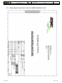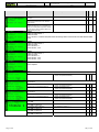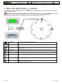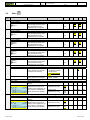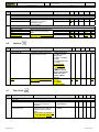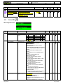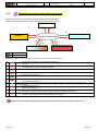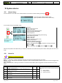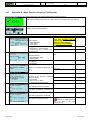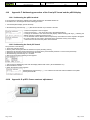
1
AFTER SALES SERVICE - REGULATION MANUAL
•
•
•
WRL
WATER / WATER CHILLER
WATER COOLED REVERSIBLE CHILLER
WATER/WATER HEAT PUMP
• SOFTWARE UPDATE
CAREL μPC vers. up 2.2.2 to 2.6.3
EN
edition February 2013
Servizio Assistenza Tecnica
Edizione 1
Pag. 2/76
Data:25/02/2013
File
Autore
Updating WRL ok ENG SAT Agg. Regolaz. Carel µPC
2.2.2-2.6.4.doc
SAT
Pag. 2/76
Pag. 2/76
Servizio Assistenza Tecnica
Edizione 1
Data:25/02/2013
File
Autore
Updating WRL ok ENG SAT Agg. Regolaz. Carel µPC
2.2.2-2.6.4.doc
SAT
Pag. 3/76
Index
CONTROL WITH THE ELECTRONIC BOARD CAREL µPC
1 Introduction ..................................................................................................................................................................................................... 6 1.1 Informations present into the text ................................................................................................................................................................. 6 2 Index of Revisions ............................................................................................................................................................................................ 7 3 Unit configuration code ................................................................................................................................................................................... 9 3.1 Parameters influenced ................................................................................................................................................................................ 10 3.2 V version with modulating valve for geothermal water flow side model Belimo ...................................................................................... 11 3.2.1 Positioning of hydraulic valve model Belimo and controls to be performed in case of problems ................................................... 11 3.2.1 Regulation parameters influenced in the case of insertion of the modulating valve model Belimo ................................................. 12 3.2.1 Wiring diagram and electric connection of MUT and Belimo valves .............................................................................................. 13 4 ModBus Network ........................................................................................................................................................................................... 15 4.1 Table of devices controlled on the ModBus network ................................................................................................................................. 15 5 User interface ................................................................................................................................................................................................. 17 5.1 pGD1 graphical terminal user guide ........................................................................................................................................................... 17 5.2 pGD1 Screen contrast adjustment .............................................................................................................................................................. 17 5.3 Structure of principal screen....................................................................................................................................................................... 17 6 Menu Wizard (password 0303) ..................................................................................................................................................................... 19 7 Menu Set Up Procedure (password 0009) ................................................................................................................................................... 23 8 Menu User (push Prg key
8.1 directly) ....................................................................................................................................................... 25 ................................................................................................................................................................................. 26 IN/OUT menu
8.2 Menù On/Off
.................................................................................................................................................................................. 27 8.2.1 Calendar .......................................................................................................................................................................................... 28 8.2.1 Solar management (at the moment only after special unit request at the time of order of the unit) ................................................ 28 8.2.2 Control Summer/Winter with external air temperature ................................................................................................................... 28 8.3 Zone Menù
....................................................................................................................................................................................... 29 8.4 Menu Chiller
................................................................................................................................................................................... 31 8.5 Menu DHW
.................................................................................................................................................................................... 31 8.5.1 Anti-legionella Treatment ................................................................................................................................................................ 32 9 10 8.6 Menu Clock
.................................................................................................................................................................................... 33 8.7 Time zones menu
............................................................................................................................................................................ 34 (password 0101).......................................................................................................................................................... 35 Menu Service
9.1 Info
................................................................................................................................................................................................. 36 9.2 Zone
................................................................................................................................................................................................ 37 9.3 Chiller
............................................................................................................................................................................................. 39 9.4 Sanitary
........................................................................................................................................................................................... 40 9.5 Pumps
9.6 Optional
9.7 Plant Conf.
9.8 User
9.9 In/Out
............................................................................................................................................................................................. 40 .......................................................................................................................................................................................... 41 ...................................................................................................................................................................................... 41 ................................................................................................................................................................................................. 42 .............................................................................................................................................................................................. 42 Factory Menu (password 0202) .................................................................................................................................................................... 44 10.1 Pag. 3/76
Conf. Alarm
............................................................................................................................................................................... 45 Pag. 3/76
Servizio Assistenza Tecnica
Edizione 1
Data:25/02/2013
File
Autore
Updating WRL ok ENG SAT Agg. Regolaz. Carel µPC
2.2.2-2.6.4.doc
SAT
Pag. 4/76
10.2 Chiller
........................................................................................................................................................................................ 47 10.3 Sanitary
10.4 Conf. Sensor
.............................................................................................................................................................................. 47 10.5 Compressors
.............................................................................................................................................................................. 48 10.6 Driver EEV
................................................................................................................................................................................ 49 ..................................................................................................................................................................................... 47 11 Regulation ...................................................................................................................................................................................................... 53 11.1 Chiller/Heat pump ................................................................................................................................................................................. 53 11.1.1 Control of Chiller temperature profile............................................................................................................................................. 53 11.1.1 Automatic differential calculation ................................................................................................................................................... 53 11.2 Conditions to exchange the mode of operation ..................................................................................................................................... 54 11.3 Low load check and force off................................................................................................................................................................ 55 11.4 Yield control alarm ............................................................................................................................................................................... 55 11.5 Auxiliary Probe B5 ............................................................................................................................................................................... 56 11.6 Drycooler system management ............................................................................................................................................................. 57 12 System alarms ................................................................................................................................................................................................ 58 12.1 Alarm history ........................................................................................................................................................................................ 58 12.2 Alarm list .............................................................................................................................................................................................. 58 13 Spare part codes for various components .................................................................................................................................................... 64 14 Setting up software version SW 2.5 .............................................................................................................................................................. 65 14.1 Programming Carel µPC board with the Carel Smart-key .................................................................................................................... 65 14.2 Addressing the EVD driver (electronic expansion valve) in pLAN network ........................................................................................ 66 14.3 Checking the configuration code of the unit ......................................................................................................................................... 67 14.4 Appendix A. Description of the unit configuration code ..................................................................................................................... 67 14.5 Appendix B. Principal screen ............................................................................................................................................................... 68 14.6 Appendix C. Input output states ........................................................................................................................................................... 70 14.7 Appendix D. Menu Service, sub-menu Conf.System ........................................................................................................................... 71 14.8 Appendix E. Menu Factory. Parameters EVD ..................................................................................................................................... 72 14.9 Appendix F. Addressing procedure of the Carel µPC board and the pGD1display .............................................................................. 75 14.9.1 Addressing the pGD1 terminal ........................................................................................................................................................ 75 14.9.2 Addressing the Carel µPC board ..................................................................................................................................................... 75 14.10 Appendix G. pGD1 Screen contrast adjustment.................................................................................................................................... 75 14.11 Appendix H. Carel uPC Internal watch ................................................................................................................................................. 76 Pag. 4/76
Pag. 4/76
Servizio Assistenza Tecnica
Edizione 1
Data:25/02/2013
File
Autore
Updating WRL ok ENG SAT Agg. Regolaz. Carel µPC
2.2.2-2.6.4.doc
SAT
Pag. 5/76
CONTROL WITH THE ELECTRONIC BOARD
CAREL µPC
Pag. 5/76
Pag. 5/76
Servizio Assistenza Tecnica
Edizione 1
Data:25/02/2013
File
Autore
Updating WRL ok ENG SAT Agg. Regolaz. Carel µPC
2.2.2-2.6.4.doc
SAT
Pag. 6/76
1 Introduction
The following document contains the substantive changes, correction of some errors and some improvements
added in the text compared to the previous document WRL ELECTRONIC REGULATION After Sales Service
Manual edition 2 March 2012 relating to software version 2.2.1 with Carel μPC electronic board of 26 October
2011.
This text will then be shown the changes, updates and various correction of equipment made from version 2.2.2 (23 April
2012) to version 2.6.4 (29 November 2012).
To aid understanding, the text parts subject to changes and updates will be anticipated by the indication
,
also parts of the text modified, added or corrected compared to the previous manual will be written in this font, and
highlighted with the color ................ also the new screens are added or changed will be seen in the following way.
(example)
In order to help understanding in the introduction of new parts included, some parts of the text of this document will be
write equal to the previous manual.
It is therefore recommended to stick to the previous WRL ELECTRONIC REGULATION After Sales Service
Manual edition 2 March 2012 as a basic text and refer this manual as an update.
Important: Regarding to the regulation of WRL cooling only units with electronic Moducontrol, remaining
unchanged the software version to 4.3.0, then follow the previous WRL ELECTRONIC REGULATION After Sales
Service Manual edition 2 March 2012 from paragraph 21
The parts of the text may be subject to update
After SalesService Department Aermec Spa
1.1
Informations present into the text
In this manual the following icons will appear to clarify particular topics or as a warning:
Highlight: provides clarification on the topic that the user should be aware of.
Suggestion: provides a suggestion that can help the user to better understand and use the information of the
topic being covered.
Attention! : provides information for which a lack of knowledge could have negative consequences on the
system or constitutes a risk to people, devices, data, etc.
Pag. 6/76
Pag. 6/76
Servizio Assistenza Tecnica
Edizione 1
Data:25/02/2013
File
Autore
Updating WRL ok ENG SAT Agg. Regolaz. Carel µPC
2.2.2-2.6.4.doc
SAT
Pag. 7/76
2 Index of Revisions
New software release features compared to the previous manual.
SW Specifiche
WRL STP_WRL
2.2.1 E33
26/10/2011
2.2.2 E33
E34
2.3
23/04/2012
30/11/2011
E37
23/04/2012
2.4.1 E38
02/05/2012
E38
27/07/2012
2.4
2.5
Data
E39
30/08/2012
2.6.2 E40
19/10/2012
2.6.3 E41
29/11/2012
2.6
Pag. 7/76
Note
Improvements:
Inserted parameter “time to pre-position EEV valve” for unipolar valves.
Faster action digital input (thermal, high pressure).
Update BIOS to 5.17, updated control function electronic valve on board µPC.
Special version that corrects only the setpoints and alarms of the modulation valve water model Belimo.
Improvements:
Insert MC18 parameter (Menu Factory) is used to delay the activation of the compressors from starting EEV valve
In addition to this version:
If is select the presence of the modulating valve side, to change the setpoint to 14.0bar and the
differential to 20.0bar (parameter P24, see the sub-menu Pumps Menu Service password 0101).
Disabled by default the parameter P34 (P34 parameter, see the sub-menu Pumps Menu Service
password 0101).
Insert the second set-point and differential of geothermal pump for heat pump function (parameter P24,
see the sub-menu Pumps Menu Service password 0101).
Insert into the parametere H43 the new functions of On/Off remote contact, according to the value
inserted, it may turn off: 0= plant + zones + sanitary function, 1= plant + zones, 2 = plant only (parameter
H43, see the sub-menu Plant Conf. Menu Service password 0101).
Improvement of hystoric alarm:
Alarm Low performance, changed the default delta temperature to 0.3 ° C and the delay time to 60s
(parameter A54, see the sub-menu Conf. Alarm Menu Factory password 0202).
Improvement compatibility of accessories:
The time displayed in the zone thermostat accessory STA (temperature only) might not be exactly.
From this version, the time displayed is synchronized with the time card Carel μPC.
Improvements:
Inserted the codes into the mask of Menu Set Up Procedure (password 0009).
Ability to see the temperature of the zone and the outdoor temperature from the thermostat accessory
STA (accessory).
From this software version the WRL units are compatible with the thermostats th-Tune Carel (accessory
STH) software version 1.3 or higher.
Improvements:
Display K22 added to control remote ON/OFF from Wizard Menu, password: 0303.
Display K23 added to control system storage from Wizard Menu, password: 0303.
Option to switch off zone pump/3-way mixer valve added during cold system running (parameters Z36,
Z48 and Z60, see Zones sub-menu in Support Menu, password: 0101).
High temperature alarm on system inlet/geothermic added; also works with unit in stand-by (parameter
A56, see Alarms Config. Sub-menu in Manufacturer’s Menu, password: 0202).
With this version, in WRL>160 units (not X or Y models), the delayed low pressure alarm threshold has
been set to 4.0bar (parameter A21, see Alarms Config. Sub-menu in Manufacturer’s Menu, password:
0202).
New version for running test with supervisory system Aerweb 300.
Improvements:
parameter MC21 added, option to invert VIC valve cycle without waiting for compressor to turn off
(parameter MC21, see Compressors sub-menu in Manufacturer’s Menu, password: 0202).
Delay time in shutting of electronic EEV thermostatic expansion valve added, after compressor turns off,
parameter MC18. This function allows the operator to equalize pressure values (parameter MC18, see
EEV Driver sub-menu in Manufacturer’s Menu, password: 0202).
In the total recovery model units, in cold operating mode, the problem tied to compressor restart during
system running in DHW only has been corrected.
Improvements:
In this version, if the flow-meter on the geothermic side triggers, all loading sequences stop and the
“alarm” symbol appears on the compressor template.
Actually in use
Improvements:
Option to turn off system pumps if zones are off added.
Room air adjustment differential default changed to 0.3°C.
Pag. 7/76
Servizio Assistenza Tecnica
Edizione 1
Data:25/02/2013
2.6.4 /
/
File
Autore
Updating WRL ok ENG SAT Agg. Regolaz. Carel µPC
2.2.2-2.6.4.doc
SAT
Pag. 8/76
Preliminary version NOT CONFIRMED !!!
rd
Compressor inlet gas high temperature safety added; allows operator to turn compressor off and turn 3
pump from off to on.
DHW pump forcing added if outlet temperature on recovery side exceeds 90.0°C
Option added to generate DHW at a higher temperature if generating cold water; allows the operator to save on
energy, by running for longer time in total recovery mode.
The latest software version is compatible with all previous.
Pag. 8/76
Pag. 8/76
Servizio Assistenza Tecnica
Edizione 1
File
Data:25/02/2013
Autore
Updating WRL ok ENG SAT Agg. Regolaz. Carel µPC
2.2.2-2.6.4.doc
SAT
Pag. 9/76
3 Unit configuration code
1 2 3
WRL
45 6
Size
WRL
SIZE
7
Field of
use
8
Model
9
Version
10
Heat
Recovery
11
Geoth.
side
pump
12
User side
pump
13
Recovery
side
pump
14
Soft
start
15
Power
supply
025 - 030 - 040 - 050 - 070 - 080 - 100 - 140 – 160
180-200-300-400-500-550-600-650
FIELD OF USE
MODEL
VERSION
HEAT
RECOVERY
GEOTHERMIC
SIDE PUMP
USER
PUMP
SIDE
RECOVERY
SIDE PUMP
SOFT-START
POWER SUPPLY
Pag. 9/76
° - Standard with leaving water above +4°C
Y – Low temperature with leaving water down to -6°C
X – Electronic expansion valve (EEV) with leaving water down to -6°C
° - Cooling (Reversible water-side)
H – Heat pump (Reversible refrigerant circuit)
E – Evaporating unit (not available for heat pump versions)
° - Standard
A – With system buffer tank
° - Without heat recovery
D - Desuperheater (ONLY FOR COOLING ONLY VERSION)
T- With total heat recovery (ONLY FOR HEAT PUMP VERSIONS
a variable flow Pump is recommended to be installed on the geothermal side)
° - Without pump
B – ON-OFF circulator with 3 speeds (models up to size 080)
Low head pump (models above size 080)
U – High head pump (models above size 080)
F – Pump suitable for phase shaving (models up to size 080)
I – Inverter pump high head (models up to size 080)
V – Modulating valve
Evaporator in cooling mode
° - Without pump
P – ON-OFF circulator with 3 speeds (models up to size 080)
Low head pump (models above size 080)
J – ON-OFF high head circulator with 3 speeds(for WRL models see section 2.3 for sizes 025-030-040)
N – High head pump (models above size 080, or for WRL models see section 2.3 for sizes from 050 to
160)
° - Without DHW pump
Q – With DHW pump
° - Without compressor soft-start
S – With compressor soft-start
° - 400V 3N~ 50Hz
M - 230V ~ 50Hz (only model sizes 025, 030, 040)
4 – 230V – 3 – 50Hz (only model sizes 050, 070, 080, 100, 140, 160)
5 – 500V – 3 – 50Hz (only model sizes 400, 550, 600, 650)
Pag. 9/76
Servizio Assistenza Tecnica
Edizione 1
3.1
Data:25/02/2013
File
Autore
Updating WRL ok ENG SAT Agg. Regolaz. Carel µPC
2.2.2-2.6.4.doc
SAT
Pag. 10/76
Parameters influenced
Added the description of the parameters influenced in relation to the application.
Field
SIZE
Description
025, 030, 040, 050,
070, 080, 100 , 140, 160
180, 200, 300, 400,
500, 550, 600, 650
OF ° - Standard with leaving water
above +4°C
Y – Low temperature with leaving
water down to -6°C
X – Electronic expansion valve
(EEV) with leaving water down to
-6°C
Parameters influenced
Sizes ≥ 100: two compressors (parameter H21 Plant Conf. Menu Service)
Sizes ≥ 100: enable thermal switch of compressor 2 (parameter H42 Plant Conf.
Menu Service)
Sizes ≥ 100: n° max compressor = 2 (parameter H21 Plant Conf. Menu Service)
Models X: enable driver EEV (parameter H27 Plant Conf. Menu Service)
FIELD
Models X and sizes ≥ 180: exthernal driver EEV (parameter H27 Plant Conf. Menu
USE
Service)
Time start-up
EEV time
forced to pre- Open valve at opening before
PID
position
start-up
start of
(parameter
(parameter
(parameter
compressor
ER9 Driver
ER3 Driver
ER3 Driver
parameter MC18
EEV Menu
EEV Menu
EEV Menu
Compressors
Factory)
Factory)
Factory)
Menu Factory)
Models X and
5.0, 60s, 1.0s
10s
30%
5s
sizes ≤100
5.0, 60s, 1.0s
10s
40%
5s
Models X and
sizes from 100
and 160
Models X and
15.0, 150s,
5s
80%
0s
sizes ≥180
5.0s
MODEL
° - Cooling (Reversible water- Models °: reversing water side (parameter H6 Plant Conf. Menu Service)
Models H: reversing refrigerant gas side (parameter H6 Plant Conf. Menu Service)
side)
H – Heat pump (Reversible Models H: enable geothermal flow-switch (parameter H30 Plant Conf. Menu
Service)
refrigerant circuit)
Models H: added probe SDHW with the unit
E – Evaporating unit (not
available for heat pump versions) Models E: disable geothermal delivery water temperature (parameter H51 Plant
Conf. Menu Service)
Models E: disable geothermal return water temperature (parameter H51 Plant
Conf. Menu Service)
VERSION
° - Standard
A – With system buffer tank
Models T: type of sanitary= Total Recovery (parameter H3 Plant Conf. Menu
HEAT
° - Without heat recovery
RECOVERY D - Desuperheater (ONLY FOR Service)
Models T: enable sanitary buffer tank probe (parameter H51 Plant Conf. Menu
COOLING ONLY VERSION)
Service)
T- With total heat recovery
Models D: type of sanitary = Desuperheater (parameter H3 Plant Conf. Menu
Service)
GEOTHERMIC ° - Without pump
Compressor
SIDE PUMP
B – ON-OFF circulator with 3
Minimum
On delay
Geoth. flowspeeds (models up to size 080)
Set. Geo. Diff. Geo. Speed/
time after
switch delay
U – High head pump (models
(parameter (parameter Opening
Geoth.
time
above size 080)
P24 Pumps P24 Pumps (parameter pump On
(parameter
F – Pump suitable for phase
Menu
Menu
P39 Pumps (parameter A45 Alarm
shaving (models up to size 080)
Service)
Service)
Menu
P12 Pumps Conf. Menu
I – Inverter pump high head
Service)
Menu
Factory)
(models up to size 080)
Service)
V – Modulating valve
Models °, B,U,F,I
17.0
12.0
15%
60s
30s
14.0
20.0
20%
110s
100s
Models V and
sizes from 025 to
080
14.0
20.0
20%
160s
150s
Models V and H
and sizes from
100 to 160
14.0
20.0
20%
110s
100s
Models V and
not H and sizes
from 100 to 160
14.0
20.0
10%
100s
90s
Models V and
sizes from 180 to
650
17.0
12.0
35%
60s
30s
Models V with
MUT modulating
valve (obsolete)
Pag. 10/76
Pag. 10/76
Servizio Assistenza Tecnica
Edizione 1
Data:25/02/2013
Field
Description
GEOTHERMIC
SIDE PUMP
USER
PUMP
File
Autore
Updating WRL ok ENG SAT Agg. Regolaz. Carel µPC
2.2.2-2.6.4.doc
SAT
Pag. 11/76
Parameters influenced
Models F,I,V: geothermal pump regulation by pressurere (parameter P21 Pumps
Menu Service)
Models B,U,F,I,V: enable thermal switch of pumps
Models P,N: enable thermal switch of pumps
SIDE Evaporator in cooling mode
° - Without pump
P – ON-OFF circulator with 3
speeds (models up to size 080)
N – High head pump
RECOVERY ° - Without DHW pump
Models Q: sanitary priority + valve or priority + pump or total recovery (parameter
SIDE PUMP
Q – With DHW pump
H3 Plant Conf. Menu Service)
SOFT-START ° - Without compressor soft-start
S – With compressor soft-start
POWER
° - 400V 3N~ 50Hz
SUPPLY
M - 230V ~ 50Hz (only model
sizes 025, 030, 040)
3.2
V version with modulating valve for geothermal water flow side model Belimo
3.2.1
Positioning of hydraulic valve model Belimo and controls to be performed in case of
problems
Important: Verify, during the unit is in off, that
the stem of the valve model Belimo is properly
oriented with respect to the direction of the fluid
(water) as shown in the picture.
In the case proceed to correctly position the
stem of the valve and reassemble the actuator
on it.
Pag. 11/76
Pag. 11/76
Servizio Assistenza Tecnica
Edizione 1
Data:25/02/2013
File
Autore
Updating WRL ok ENG SAT Agg. Regolaz. Carel µPC
2.2.2-2.6.4.doc
SAT
Pag. 12/76
Pictures about the positions of Belimo valve
3.2.1
Field
FIELD OF
USE
Regulation parameters influenced in the case of insertion of the modulating valve model
Belimo
Description
° - Standard with leaving
water above +4°C
Y – Low temperature with
leaving water down to -6°C
X – Electronic expansion
valve (EEV) with leaving
water down to -6°C
GEOTHERMIC ° - Without pump
SIDE PUMP
B – ON-OFF circulator with 3
speeds (models up to size
080)
U – High head pump (models
above size 080)
F – Pump suitable for phase
shaving (models up to size
080)
I – Inverter pump high head
(models up to size 080)
V – Modulating valve
Pag. 12/76
Parameters influenced
X: enable driver EEV (parameter H27 Plant Conf. Menu Service)
X and sizes > 160: exthernal driver EEV (parameter H27 Plant Conf. Menu Service)
X and sizes > 160: PID = 15.0, 150s, 5.0s (parameter ER9 Driver EEV Menu Factory)
Exthernal Driver
X and sizes ≤ 160: PID = 5.0, 60s, 1.0s (parameter ER9 Driver EEV Menu Factory)
Driver on board
X and sizes ≤ 160: start compressor delay time from EEV 5s (parameter MC18
Driver EEV Menu Factory)
X and sizes < 100: valve open during the start = 30% (parameter ER3 Driver EEV
Menu Factory)
X and sizes from 100 to 180: valve open during the start = 40% (parameter ER3
Driver EEV Menu Factory)
X and sizes < 180: time start-up forced to pre-position =10s (parameter ER3
Driver EEV Menu Factory)
X and sizes ≥ 180: open valve at start-up = 80% (parameter ER3 Driver EEV Menu
Factory)
F,I,V: select regulation geothermal pump by high pressure (parameter P21 Pumps
Menu Service)
B,U,F,I,V: enable pump thermal switch
V and sizes < 160: minimum speed of geothermal pump = 20% (parameter P39
Pumps Menu Service)
V and sizes ≥ 160: minimum speed of geothermal pump = 10% (parameter P39
Pumps Menu Service)
V and sizes < 160: MUT model valve, minimum speed of geothermal pump = 35%
(parameter P39 Pumps Menu Service)
V and sizes from 025 to 080: delay time start compressor from start pump =110s
(parameter P12 Pumps Menu Service)
V and sizes from 025 to 080: delay time of geothermal flow-switch during the
start = 100s (parameter A54 Alarm Conf. Menu Factory)
V and H and sizes from 100 to 160: delay time start compressor from start pump
=160s (parametro P12 Pompe Menu Assistenza)
V and H and sizes from 100 to 160: delay time of geothermal flow-switch during
the start = 150s (parameter A54 Alarm Conf. Menu Factory)
V and sizes > 160: delay time start compressor from start pump =100s (parameter
P12 Pumps Menu Service)
V and sizes > 160: delay time of geothermal flow-switch during the start = 90s
(parameter A54 Alarm Conf. Menu Factory)
V with MUT valve: delay time start compressor from start pump =60s (parameter P12
Pumps Menu Service)
V with MUT valve: time of geothermal flow-switch during the start = 90s (parameter
A54 Alarm Conf. Menu Factory)
V:high pressure setpoint condensation 17.0bar (parameter P24 Pumps Menu Service)
V: differential condensation pressure 12.0bar (parameter P24 Pumps Menu Service)
Pag. 12/76
Servizio Assistenza Tecnica
Edizione 1
3.2.1
Pag. 13/76
Data:25/02/2013
File
Autore
Updating WRL ok ENG SAT Agg. Regolaz. Carel µPC
2.2.2-2.6.4.doc
SAT
Pag. 13/76
Wiring diagram and electric connection of MUT and Belimo valves
Pag. 13/76
Servizio Assistenza Tecnica
Edizione 1
Pag. 14/76
Data:25/02/2013
File
Autore
Updating WRL ok ENG SAT Agg. Regolaz. Carel µPC
2.2.2-2.6.4.doc
SAT
Pag. 14/76
Pag. 14/76
Servizio Assistenza Tecnica
Edizione 1
Data:25/02/2013
File
Autore
Updating WRL ok ENG SAT Agg. Regolaz. Carel µPC
2.2.2-2.6.4.doc
SAT
Pag. 15/76
4 ModBus Network
The Carel µPC board does not have sufficient inputs and outputs to cover all functions.
Thanks to a port named “Field Bus”, terminal J10 of the board, “the application” is capable of controlling various
slave boards in ModBus protocol (Carel pCOe expansion board).
4.1
Table of devices controlled on the ModBus network
The devices installed must all be connected to the ModBus serial network.
Remember to install a 120 Ohm resistor between Tx+ and Tx- at the beginning and end of the serial network
Address
1
2
3
4
5
10
11
12
16
Device connected
Zone 1, Room 1 directly
controlled from the Carel
µPC board
Zone 2, Room 1 (STA/H)
Zone 2, Room 2 (STA/H)
Zone 3, Room 1 (STA/H)
Zone 3, Room 2 (STA/H)
pCOe Accessory
pCOe Zone 2
pCOe Zone 3
Solar kit pCO compact
To address the Carel pCOe boards it is sufficient to change the dip-switches
of the expansion boards.
Modified explanation for addressing thermostats STA / STH
To address the STA/H (TH-Tune) room sensor requires:
1.Power up the device
2. Press FAN and POWER for 5 sec.
3. Enter the password 22, and press PUSCH
4. Turning the adjustment knob - PUSH +, search the wording “addr”.
5. Having found “addr”, press - PUSH + and enter the address comprised
between 1 and 5, press - PUSH + to confi rm
6. Turning the adjustment knob- PUSH +, search the wording “esc”, press PUSH +, to confirm and exit.
Added explanation of the function of the buttons and icons that appear on the thermostat Carel th-Tune
Pag. 15/76
Pag. 15/76
Servizio Assistenza Tecnica
Edizione 1
Data:25/02/2013
File
Autore
Updating WRL ok ENG SAT Agg. Regolaz. Carel µPC
2.2.2-2.6.4.doc
SAT
Pag. 16/76
A Shows that it is the season WINTER
B Shows that it is the season SUMMER
C Mosta the value of ambient temperature or the current setpoint
D Indicates the unit of measure to which it refers
E Indicates that the value displayed is the setpoint
F OFF indicates force in the time bands
G Indicates the day of the week
H Indicates that an alarm is active
I Indicates that the pump area is active
L Indicates that the function is active dehumidifi cation
M Indicates the lack of hot water (the water temperature of the area, compared to the set, is lower than two times its differential)
N Indicates the lack of water freddda (the water temperature of the area, compared to the set, is higher than two times its differential)
O Indicates the system time or the humidity value (if applicable)
Pag. 16/76
Pag. 16/76
Servizio Assistenza Tecnica
Edizione 1
File
Data:25/02/2013
Autore
Updating WRL ok ENG SAT Agg. Regolaz. Carel µPC
2.2.2-2.6.4.doc
SAT
Pag. 17/76
5 User interface
5.1
pGD1 graphical terminal user guide
Like the unit’s interface, the user has available a semi-graphical terminal named pGD1.
Through the pGD1 panel the complete unit status can be seen and it is possible to work on the parameters for
configuration of the unit.
The various menu structures and displays are designed to be functional and easy to use.
The pGD1 terminal, shown in the preceding figure, has six keys with
the following functions:
Displays active alarm list and historical alarm list
- Alarm Red LED illuminated = at least one active alarm
Displays the Menu User
Orange LED illuminated = winter mode
Returns to previous screen
Upwards flow of a list or increases the value shown on
- Up
the display
Downwards flow of a list or decreases the value shown
- Down on the display
Enter
5.2
Enters the selected sub-menu or confirms the value set
pGD1 Screen contrast adjustment
To adjust the contrast of the display, press the keys with Alarm and
Prog
Alarm
View the list of active alarms and alarm history
Red LED on = at least one active alarm
Displays the main menu.
Orange LED on = heating mode
Scrolls the list up or allows to increase the value on the
display.
Scroll down or a list allows you to decrease the value
shown on the display.
5.3
Structure of principal screen
The principal screen provides the user various information through
icons
Pressing the
key enters the Menu IN/OUT
Pressing the
key enters the Menu ON/Off and change of season
The description of the displays present is detailed below.
Icon
Display
Upper
Part
- on/off
Description
The whole system (radiant panels, chiller, fan coil unit, solar kit and DHW) is enabled for operation
Unit active in Economy mode
winter
sum.
22:56 Wed
Pag. 17/76
SEASON: indicates the mode of operation of the system; Summer or Winter
DHW: indicates the presence of the DHW tank
HOUR and DAY: h:min and day of the week
Pag. 17/76
Servizio Assistenza Tecnica
Edizione 1
Data:25/02/2013
Icon
Display
Central
Part
Display
Central
Part
Display
Lower
Part
File
Autore
Updating WRL ok ENG SAT Agg. Regolaz. Carel µPC
2.2.2-2.6.4.doc
SAT
Pag. 18/76
Description
Temperature the system is controlling to (outlet temp sensor B7)
Temperature DHW (sensor B3)
Operating status and active device
Indicates a preventative action is in operation
Indicates Off by system time-clock
Activates if the supplementary system (immersion heater of boiler) are in operation. If the “solar panels” icon is active at
the same time only the latter is displayed
Activates if one or more solar panels are installed and active
Activates when the geothermal freecooling is active. It is alternative to the functioning of the compressor(s)
Activates when a compressor is active, if there is a “2” within the icon it means two compressors are active
Activates when a DHW pump is active
Activates when there is a DHW request in a system with water device valve. Flashes during timing of changeover
Activates when the system pump is active.
If it flashes it means that the pump is on but not enough time has passed to allow the enabling of the compressor(s)
Activates when the pump on the geothermal side is active.
If it flashes it means that the pump is on but not enough time has passed to allow the enabling of the compressor(s)
The operational status for the unit available is the following
:
Added new operating states and their meaning
Status
Off
On
0
1
2
Alarm Off
3
Antifr.
Super.Off
Fasc.Off
DigIN Off
Off
Protect
Antileg.
Chiller
Sanitario
P.C.
Ch+San.
Pag. 18/76
4
5
6
7
8
9
10
11
12
13
Description
The system is in stand-by
The system is active and functioning
A serious alarm is present which has stopped the system, check the list of active alarms pressing the
key
The air temperature of the rooms measured by the probes STA / STH go down below the set point
(default 6.0 ° C)
The supervisory system has inhibited the start of the unit
The entire system shut down in Off by clock calendar
The digital input (ID8) is closed and places the system OFF
Off by pGD1
An anti-freeze protection has triggered. Anti-freeze function
The anti-legionella function of the DHW side is active
The unit working to produce cooling water for the plant
The unit working to produce DHW heating water
The unit working to produce heating water for the plant
The unit working to produce cooling water for the plant and DHW heating water
Pag. 18/76
Servizio Assistenza Tecnica
Edizione 1
6
File
Data:25/02/2013
Autore
Updating WRL ok ENG SAT Agg. Regolaz. Carel µPC
2.2.2-2.6.4.doc
SAT
Pag. 19/76
Menu Wizard (password 0303)
To speed up the WRL unit start-up it is possible to use the following start-up procedure.
Mask
Description
At first power up the selection of the available languages is asked “see language section” and the
password will be requested
This screen appears after the first power up of the unit and can be returned to
Press the Prog key and enter the Menu Service then press Enter and enter the password 0303
As long as the configuration Wizard is not completed an alarm will be generated (not history logged)
Once in the Menu Wizard it is possible to run though the list of screens using the keys
The chosen screen is selected pressing the
.
key.
To modify the parameter(s) or content(s) of the screen use the
and
and
key and to modify the parameter(s) use the
keys. To confirm the required modification press the
key.
Modified some masks and descriptions and insert new masks with completly new descriptions.
Mask
Description
Values descriptions
D
e
f
0
Select if a DHW tank is present and how it 0. NOT PRESENT
is controlled
1. TOTAL RECOVERY (N.B. forced if digit T is
inserted in the Menu start-up procedure password
0009)
= Not present
2. PRIORITY.+ VALVE = DHW with valve
3. PRIORITY + PUMP = DHW with twin pump
= Total Recovery
M
i
n
M
a
x
1
3
= Sanitary + valve
= Sanitary + pump
The units with total heat recovery built after The unit will produce hot water based on the outlet
May 2011 have a sensor mounted in the heat heat recovery temperature and only if requested by
the DHW tank sensor
exchanger.
To simplify selection the value of the sensor
is displayed
0
0
1
Selects if the system pump is before or after 0. UPSTREAM
1. DOWNSTREAM
the water-side reversing valve.
0
0
1
0
1
0
Displayed if unit with water-side reversing
Outdoor temperature present
Pag. 19/76
0. NO
1. YES
Pag. 19/76
Servizio Assistenza Tecnica
Edizione 1
Mask
Data:25/02/2013
File
Autore
Updating WRL ok ENG SAT Agg. Regolaz. Carel µPC
2.2.2-2.6.4.doc
SAT
Description
Values descriptions
D
e
f
M
i
n
M
a
x
Geothermal freecooling capability
0. NO
1. YES
0. NO
1. YES
0
1
0
0
1
0
0. NONE
1. BOILER
2. HEATING EL.
--0: Hp INTEGRATION
1: Hp REPLACEMENT
0
1
2
0
1
1
Solar panel heating control capability
Select supplementary system heating
Method of supplementary heating
Select DHW supplementary heating.
If immersion heater is chosen it enables
the anti-legionella function
Method of DHW supplementary heating
ON/OFF unit selection if is present the
remote contact.
It is possible decide the logic of
intervention and the type of action
(parameter H43 sub-menu Plant Conf .
Menu Service password 0101)
0. NONE
1. BOILER
2. HEATING EL.
--0: Hp INTEGRATION
1: Hp REPLACEMENT
Logic: Open/Closed = Unit ON
Activated on:
Plant+Zones
+Sanitary
Shut in Off all system if
it is activated
Plant+Zones
Shut in Off plant and
zones
Shut in Off the plant
only
Plant only
In case the system has a water storage
0 Unit in ON
tank is possible to move the control probe 1 COMP.
within this accumulation and turn on the
(compressor)
pump system only if is necessary.
request
0
1
In the case of a mixed system the device
requiring the hottest water temperature must
be indicated.
NB: in the case of a system with fan coil units
or radiators it is not intended to install the
pCOe expansion boards or the STA/H
temperature/humidity sensor
In the case of a mixed system the device
requiring the coldest water temperature
must be indicated.
NB: in the case of a system with fan coil
units or radiators it is not intended to install
the pCOe expansion boards or the STA/H
temperature/humidity sensor
With a water/glycol mix it is possible to
produce lower temperatures so if a value
other than 0% is used the following alarms
are automatically modified:
LOP (AL=91), LowTemp (AL097) = with EEV
valve
Pag. 20/76
Pag. 20/76
Plant pump always in ON
Plant pump is activated
with compressor
requested
OUTLET TEMP.
INLET TEMP.
Value
0 RADIANT FLOW
1 FANCOILS
2 RADIATOR
3 MIX, Set 40°C
Winter Set point
35,0
45,0
55.0°C
40,0
Summe Plant
r set- Antifreeze
set-point
point
Type
0 RADIANT FLOW
1 FANCOILS
2 RADIATOR
3 WATER GLICOLE
0%
4 WATER GLICOLE
10%
5 WATER GLICOLE
20%
6 WATER GLICOLE
>20%
17,0
12,0
12,0
7,0
4.0
4.0
4.0
4.0
7,0
-1.0
1.0°C
7,0
-10.0
-8.0°C
7,0
-10.0
-8.0°C
Evap Low
temperature
[°C]
1) 10%
-1.0
-7.0
-4.0
2) 20%
-10.0
-13.0
-9.0
1
2
0
1
1
0
1
2
0
0
1
0
0
1
3
1
2
3
Setpoint
limits
6.0°C
6.0°C
6.0°C
6.0°C
Glicol % Geo
LOP
Antifreeze [°C]
set-point
[°C]
0) 0%
4.0
-2.0
0
0
0
0
2.0
Pag. 20/76
6
2
Servizio Assistenza Tecnica
Edizione 1
Mask
Data:25/02/2013
File
Autore
Updating WRL ok ENG SAT Agg. Regolaz. Carel µPC
2.2.2-2.6.4.doc
SAT
Pag. 21/76
Description
Values descriptions
D
e
f
M
i
n
M
a
x
Maximum number of zones that can be
controlled
---
1
0
3
1
0
1
Inserting 1 the Carel µPC board can directly --control one zone and one room with the
STA/H sensor
--1
0
2
In the case of other radiant zones being
present inserting 2 or 3 it is necessary to
install one or two pCOe expansion boards
(one per zone) and to install at least one
STA/H sensor per room
Example:
Number of radiant zones: 1
Number of rooms
Zone 1: select 0 or 1 and the Carel µPC board can directly control one zone and one room with the STA/H
sensor.
Example:
Number of radiant zones: 2
Number of rooms
Zone 1: select 0 or 1
Zone 2: select 0, 1 or 2
Example:
Number of radiant zones: 3
Number of rooms
Zone 1: select 0 or 1
Zone 2: select 0, 1 or 2
Zone 3: select 0, 1 or 2
Example:
Screen complete
Zone 1
Type of device
Type of sensor connected to Room 1
Zone 2
Type of device
Type of sensor connected to Room 1
Type of sensor connected to Room 2
Zone 3
Type of device
Type of sensor connected to Room 1
Type of sensor connected to Room 2
Personalised name of Room 1
Screen K42
Personalised name of Room 2
Screen K45 not displayed
Personalised name of Room 3
Screen K48 not displayed
Personalised name of Room 4
Screen K51 not displayed
Personalised name of Room 5
Screen K54 not displayed
Pag. 21/76
0. STA/H Temperature only
1. STA/H Temperature/Humidity
0
0
1
0. STA/H Temperature only
1. STA/H Temperature/Humidity
0. STA/H Temperature only
1. STA/H Temperature/Humidity
0
0
1
0
0
1
0. STA/H Temperature only
1. STA/H Temperature/Humidity
0. STA/H Temperature only
1. STA/H Temperature/Humidity
0
0
1
0
0
1
A…Z and from 0..9 and “+” “-“
--
0
38
A…Z and from 0..9 and “+” “-“
--
0
38
A…Z and from 0..9 and “+” “-“
--
0
38
A…Z and from 0..9 and “+” “-“
--
0
38
A…Z and from 0..9 and “+” “-“
--
0
38
Pag. 21/76
Servizio Assistenza Tecnica
Edizione 1
Data:25/02/2013
Mask
File
Autore
Updating WRL ok ENG SAT Agg. Regolaz. Carel µPC
2.2.2-2.6.4.doc
SAT
Pag. 22/76
Description
Values descriptions
D
e
f
M
i
n
M
a
x
Setting type of BMS protocol
0. --1. CAREL RS485
2. ModBus RS485
3.VMF
0. 1200
1. 2400
2. 4800
2
0
3
4
0
4
Setting speed of BMS protocol
Select address number for BMS protocol
To insert the new Assistance password the
old password must first be inserted
On completion of the configuration the
existing parameters are over-written with
those from the Menu Wizard.
The language selection is disabled.
The Wizard not configured alarm is reset.
Returns to the initial screen
3. 9600
4. 19200
200 1
207
000 999 101
0
9
0.NO
1.YES
No No
Si
IMPORTANT: From software version 2.3.0 it is possible to have directly access to Menu Service (with
password to access) from the Menu User simply by pressing the
Pag. 22/76
key.
Pag. 22/76
Servizio Assistenza Tecnica
Edizione 1
File
Data:25/02/2013
Autore
Updating WRL ok ENG SAT Agg. Regolaz. Carel µPC
2.2.2-2.6.4.doc
SAT
Pag. 23/76
7 Menu Set Up Procedure (password 0009)
Group of hidden screens, DO NOT DIVULGE THE EXISTENCE.
To speed of the set-up procedure at the Aermec office this group of hidden screens were created.
If required by the Technical Assistance Service, this menu can be accessed on site where the unit is
installed to verify the particular WRL unit configuration inserted into the characteristics label.
To access this group of screens insert the password 0009 from the Menu Service.
Mask
Description
Press the Prog key and enter the Menu Service (see dedicated section) then press Enter
and insert the password 0009
The password is always fixed at 0009
The password displayed will return to 0 after 5 minutes of inactivity of the user terminal.
Once in the Menu set-up procedure it is possible to run though the list of screens using the keys
The chosen screen is selected pressing the
key.
To modify the parameter(s) or content(s) of the screen use the
and
and
key and to modify the parameter(s) use the
keys. To confirm the required modification press the
key.
Changed all screens and add new meanings
Mask
Description
WRL unit configuration.
The unit is configured in accordance with the
symbols inserted in the spaces provided.
At the end of the configuration the verification of the
“code” is requested.
N.B.: the code and the date inserted are
memorised in the Menu Info of the Menu Service
password 0101.
HP e High pressure and compressor discharge Push the Enter key to display the
TGP temperature
saturation temperature
LP
SH
P
G
e Low pressure and super heating
Push the Enter key to display the
saturation temperature
Pumps status and countdown time for compressor/s start
----- s
----- s Minimum time in OFF and minimum time in ON
----- s
Compr Compressor/s status
Pag. 23/76
Pag. 23/76
Servizio Assistenza Tecnica
Edizione 1
Data:25/02/2013
Mask
File
Autore
Updating WRL ok ENG SAT Agg. Regolaz. Carel µPC
2.2.2-2.6.4.doc
SAT
Description
Forced accelerated timings like:
Pag. 24/76
Forced accelerated timings like:
N.B. If power is removed then reN.B. If power is removed then re-instated the
instated the timings return to default
timings return to default values
values
System WINTER: ON/OFF of the system and select SUMMER/WINTER. Parameter the same as
screen u3 (Menu ON/OFF of the Menu User).
N.B.: the selection SUMMER/WINTER can only be changed with the unit off.
Set. Sys. Summer: System cooling water setpoint. Parameter the same as screen S3 (Menu Chiller
of the Menu User)
Set.Sys.Winter: System heating water setpoint. Parameter the same as screen S6 (Menu Chiller of
the Menu User)
Al. Antif. Geo: anti-freeze alarm setting of the outlet side (geothermal). Parameter the same as
screen (Menu Conf. Alarm of the Menu Factory password 0202).
Al. Antif. Sys.: anti-freeze alarm setting of the system side. Parameter the same as screen A6
(Menu Conf. Alarm of the Menu Factory password 0202).
Al. Low Pres.: low pressure alarm setting. Parameter the same as screen A21 (Menu Conf. Alarm of
the Menu Factory password 0202).
Al. High Pres.: high pressure alarm setting. Parameter the same as screen A18 (Menu Conf. Alarm
of the Menu Factory password 0202)
Superheat: state of the suction refrigerant super heat.
State EEV: state of percentage opening of the electronic expansion valve.
Valve opening at start-up: set opening of the electronic expansion valve.
Forced manual: Valve forced manual with value of modification “stp” = step
Forced operation of geothermal pump
Forced operation of plat pump
Forced operation of heater plant
Forced operation of sanitary pump
Forced operation of DHW heater
Forced operation of compressor 1.
Forced operation of compressor 2.
Forced operation of inversing cycle valve refrigerant circuit
Forced operation of free-cooling
Forced operation of dehumidifiers
Forced operation in percentage of sanitary pump
Forced operation in percentage of geothermal pump
Forced operation in percentage of valve zone 1
Forced operation in percentage of dehumidifier
Forced operation pumps Zone 1, 2 and 3.
Cancellation historical alarm.
To carry out at the end of set-up in factory or as required by technical
assistance service after consultation and verification with the factory.
IMPORTANT: From software version 2.3.0 it is possible to have directly access to Menu Service (with
password to access) from the Menu User simply by pressing the
Pag. 24/76
key.
Pag. 24/76
Servizio Assistenza Tecnica
Edizione 1
Data:25/02/2013
8 Menu User (push Prg key
File
Autore
Updating WRL ok ENG SAT Agg. Regolaz. Carel µPC
2.2.2-2.6.4.doc
SAT
Pag. 25/76
directly)
From the principal screen, which appears when turned on, press the Prg key to access the Menu User without having to
enter the access password.
The various menus seen from within Menu User contain further view only screens or adjustable parameters. With
the “arrow” keys move through the sub-menus shown or access via the “enter” key for any modifications.
For example, within the Menu Zone all the parameters for the control of the radiant zones are found.
Pag. 25/76
A) IN/OUT
Status of the WRL system various parts
B) ON/OFF
On and off of the unit. change of season and time-clock
C) ZONE
Control of radiant zones (parameters of the STA/H, Th-Tune sensor (s)) and selection of
the time-clock
D) CHILLER
CHILLER parameter (Chiller, PdC, condensing), set point comfort and Economy
E) SANITARY
Set point, enable, temperature, time-clock
F) CLOCK
Date, hour, change of Winter, Summer time
G) TIME ZONE
Selection of 5 programmes of the radiant zones with 2 time-clocks
H) SERVICE
Assistance, from which other menus can be accessed (password 0101 Menu Service,
password 0202 Menu Factory)
Pag. 25/76
Servizio Assistenza Tecnica
Edizione 1
Data:25/02/2013
8.1
File
Autore
Updating WRL ok ENG SAT Agg. Regolaz. Carel µPC
2.2.2-2.6.4.doc
SAT
Pag. 26/76
IN/OUT menu
In this menu it is possible to have a summary of the unit operation.
Changed some masks with the addition of new meanings
Mask
Description
Indicates the actual outdoor air temperature and the minimum and maximum temperatures
recorded during the night and day
Screen visible if enabled air external probe, parameter K12 Menu Wizard password 0303.
Indicates the inlet/outlet temperatures within the heat exchangers of the geothermal side and
system side
Icon
Description
pump geothermal side active
pump system side active
4 way valve displayed with black head if enabled
flow switch open
system pump forced on to overcome low pressure
prevention high system outlet water temperature
prevention low system outlet water temperature
anti-freeze heater active due to low temperature
system demand 0 - 100%
Indicates the suction and discharge pressures of the compressor and the discharge
temperature.
Also shows if the compressor is on or off:
Status
Meaning
0
Off
Compressor/s off
1
On
Compressor/s on
2
Min.On
Compressor/s on and in coutdown time of minimum on
status
3
Min.Off
Compressor/s off and in coutdown time of minimum off
status
4
Allarme
Compressor/s in alarm
5
Forz.Off
Compressor/s forced in off
6
Forz.On
Compressor/s forced in on
7
--Compressor not configured (second compressor)
The screen gives useful information of the state of the electronic expansion valve such as super
heat (SH), the suction pressure and its suction temperature and refrigerant evaporating
temperature (Suct.).
LOP = prevention of low suction pressure, MOP = prevention of high suction pressure.
LSH = prevention low super heat.
= alarm present on the electronic expansion valve driver.
Screen visible if is present the electronic expansion valve, code X insert into model of
unit, see Menu Set Up Procedure password 0009
Pag. 26/76
Pag. 26/76
Servizio Assistenza Tecnica
Edizione 1
File
Data:25/02/2013
Mask
Autore
Updating WRL ok ENG SAT Agg. Regolaz. Carel µPC
2.2.2-2.6.4.doc
SAT
Pag. 27/76
Description
Indicates the water temperature of the DHW tank, outlet water temperature, the setpoint used
and the relative differential. In addition the following symbols mean,
anti-legionella active,
DHW pump running,
off by time-clock.
The icon “
“ indicates that the DHW pump is forced on to overcome a low pressure (suction
pressure) of the refrigerant circuit.
Other information is shown in the following table:
0
1
2
3
4
5
6
7
8
9
Status
--On
Alarm
Comp Off
Unit Off
Time-Cl Off
Ingr.IDg
Off key
Manual
Antilegion.
Meaning
The system is off
The system is available to produce DHW
An alarm relating to DHW is present
With the desuperheater the DHW does not work with compressor off
The central system has inhibited the starting of all devices
DHW is disabled by time-clock
DHW is disabled by digital input ID8
DHW is disabled by user
DHW is forced on by digital input
Anti legionella function
Screen visible if is insert the presence of DHW parameter K6 Menu Wizard password
0303 or parameter H3 sub menu Plant Comf., Menu Service password 0101.
The modulation of the geothermal side flow rate is used to stabilise the condensing pressure.
In this screen the operating setpoint and differential can be seen and the pressure and
temperature seen by the sensors and percentage opening of the valve or the percentage
speed of the pump inverter.
The icon “
“ indicates that the DHW pump is forced on to overcome a low pressure (suction
pressure) of the refrigerant circuit.
NB. In heat pump mode with head pressure control the opening of the valve or the speed of the
pump inverter is fixed at’ 80%.
The screen indicates that the drycooler system is in operation (see the enabling in the submenu Accessory of the Menu Service screen B27 and B30).
Shows the percentage opening of the mixing valve/percentage speed of the fans relative to
output Y1 (0-10V) of the pCOe expansion board accessory.
In screen B27 the sensor can be selected which the thermostat uses; in this case the
geothermal side return sensor.
As well determine the operating Setpoint and differential
Screen visible if is insert the presence of dry cooler, parameters present into sub-menu
Optional, Menu Service screens B27 and B30.
8.2
Menù On/Off
Added new meanings
Mask
Pag. 27/76
Description
From the first row of the screen selection it is possible to change the state of the unit:
•
OFF (the whole system will be placed in off mode)
•
ON (the controlled supply of hot/cold water is enabled)
•
ECONOMY (the system will control with setpoints adjusted for energy saving)
•
ON BY TIMEZONE Time-clock (the system runs in accordance with the time-clock
settings)
In the second row of the screen selection (visible only if OFF selected in the first row) it is
possible to select the change of season
•
SUMMER
(production of cold water)
•
WINTER
(production of hot water)
•
DHW ONLY (this mode envisions that the unit works only for the production of DHW)
•
AUTO BY TEMP.EXT (outdoor ambient sensor if present)
Pag. 27/76
Servizio Assistenza Tecnica
Edizione 1
Data:25/02/2013
Schermata
File
Autore
Updating WRL ok ENG SAT Agg. Regolaz. Carel µPC
2.2.2-2.6.4.doc
SAT
Pag. 28/76
Significato
If the AUTO Time-clock function is selected the following screens allow setting of the unit’s
time-clock.
Note that the selections possible are:
--- = time-clock not used. Unit off
Comfort (nominal setpoint)
Eco (economy setpoint)
4 time-clock programmes can be selected per day, over the 7 days of the week
Screen visible if is enable ON BY TIMEZONE into the previous screen u3 Menu ON/OFF.
Entering this screen and modifying Copy in --- (default) in Copy in ALL and confirming with
YES the time-clock programmes determined for one day can be copied for all days of the
week.
Screen visible if is enable ON BY TIMEZONE into the previous screen u3 Menu ON/OFF.
8.2.1
Mask
Calendar
Description
Each programme has a “special” day called Holiday (Hol)
This day can be called from the function available in the “Calendar” screen
In this screen up to 5 actions can be enabled.
Each action has a start and stop date and the can be selected to switch off the system or
enable the whole system for the holiday
Screen visible if is enable ON BY TIMEZONE into the previous screen u3 Menu
ON/OFF.
8.2.1
Mask
Solar management (at the moment only after special unit request at the time of order of
the unit)
Description
Within this screen the solar heating module can be switched on or off.
The screen appears if the Solar control is enable in the Menu Wizard password 0303
8.2.2
Mask
Control Summer/Winter with external air temperature
Description
If the presence of the external ambient sensor is selected in the Menu Wizard password
0303 in screen K12 and if in the preceding screen u3 the function AUTO from TEMP.EXT is
selected (change of season from external temperature sensor); in this screen it is possible to
enter the change of season limits.
If the temperature is within the two limits the unit will maintain the mode of operation it had
previously.
Example: If the operating mode is winter, because the external air temperature is lower than
the summer activation setting of 26°C, the operating state remains the same until the
summer setting is exceeded. When the summer mode operates because the setpoint of
26°C is exceeded, this mode will be maintained until the lower setting of 7°C is passed which
will activate the winter mode operation.
N.B. The change of season does NOT switch off the unit
Screen visible if is enable AUTO BY TEMP.EXT into the previous screen u3 Menu
ON/OFF.
Pag. 28/76
Pag. 28/76
Servizio Assistenza Tecnica
Edizione 1
Data:25/02/2013
8.3
File
Autore
Updating WRL ok ENG SAT Agg. Regolaz. Carel µPC
2.2.2-2.6.4.doc
SAT
Pag. 29/76
Zone Menù
Changed some masks with the addition of new meanings
Mask
Description
Screen/s visible if is enable at least one zone
To each ROOM controlled by a STA/H (Th-tune) room sensor a summary screen is available
which through icons provides the user various system functioning information.
Example: Screen visible if is enable the room 1 of zone 1.
The following shows the description of the information available
Mask
1.1
ROOM 1
Description
Number given to room
Name of the room (personalised in the service section)
PROGRAM: indicates association of the room
- on/off
The room is enabled
23.0°C (example)
Room air temperatura
winter
summer
Humidity: 64.3% (example)
Set active: 20.0°C
(example)
SEASON: indicates the mode of operation of the room
Relative humidity of the room (if present)
Active setpoint of the room
Activates when there is a heat/cool demand
Indicates activation of the dehumidifier
Room disabled (operate in the next screen to switch on the room)
Off from time-clock
Room enabled for operation
The Status of operation in which one can find the room are the following:
Status
Description
On
Alarm Off
Unit.Off
Status
Disabl.
Off Sched.
DigIN Off
Off tasto
The room is active and functioning
An alarm is present in the room (check the active alarm list pressing the alarm key)
The central system has inhibited the start of all the zones
Description
The room is not configured (check service/assistance parameters)
The room is disabled by the time-clock (check the associated programme)
Disabled by input to the pCOe (only with configuration Th-tune disabled)
The room is disabled by the user
Mask
Pag. 29/76
Description
The screen indicates the temporary control setpoint that the room sensor is working to, in this
screen ROOM 1 is shown.
The operating setpoint limits can be modified in the Menu Service password 0101, in sub-menu
Zone.
The room can be switched on or off through the “Enable room” setting.
P.S. If the time-clock operates this setpoint is overwritten each time the time-clock is
updated.
Screen visible if is enable the room 1 of zone 1.
Pag. 29/76
Servizio Assistenza Tecnica
Edizione 1
Mask
Data:25/02/2013
File
Autore
Updating WRL ok ENG SAT Agg. Regolaz. Carel µPC
2.2.2-2.6.4.doc
SAT
Pag. 30/76
Description
The screen indicates the time-clock to which the room is associated, in this screen ROOM 1 is
shown.
N.B. In the case other rooms are activated in the Menu Wizard password 0303 (if the
respective pCOe expansion boards are installed) the following additional screens will
appear:
- r15 and r18 for ROOM 2
- r24 and r27 for ROOM 3
- r33 and r36 for ROOM 4
- r42 and r45 for ROOM 5
In this way specific setpoints in specific time-clock settings of the day can be controlled.
PS: The programmes associated to the rooms are controlled from within the Menu timeclock
Screen visible if is enable the room 1 of zone 1.
The screen indicates the dehumidifier setpoints of Zones 1, 2 and 3.
The operating limits must be adjusted from the Menu Service in the sub-menu Zone
Screen visible if is enable at least one zone
The screen indicates the humidifier setpoint.
The operating limits must be adjusted from the Menu Service in the sub-menu Zone
Screen visible if is enable at least one zone
The screen shows various information on the state of Zone 1:
- The pump of the active zone is shown with the P circled
- Deliv. 50.8°C (example): The water temperature of the zone
- Set 30.0°C (example): The active setpoint at that time
- Diff 4.0°C (example): The active differential at that time
- Valv. 000% (example): The state of the mixing valve 0..10 Volt
- The state of the zone may be: On, Alarm, Manual, Disabl., Room Off, Off Rem, Unit Off
N.B. In the case other zones are activated the following screens will also appear always
with the same indications:
r57 for ZONE 2
r60 for ZONE 3
The screen indicates the chilled water Setpoint, example Zone 1 (screen r72 for Zone 2 and
r78 for Zone 3).
Zone 1
Setpoint water in cooling mode
Setpoint water in heating mode
The operating limits must be adjusted from the Menu Service in the sub-menu Zone
Example: Screen visible if is enable “FIXED SETPOINT” into the parameter Z36 submenu Zone, Menu Service password 0101.
The screen indicate the water setpoint in heating mode, example Zone 2.
The limits of the operating range can be changed in the Menu Service, sub-menu Zone
Example: Screen visible if is enable “FIXED SETPOINT” into the parameter Z36 submenu Zone, Menu Service password 0101.
Pag. 30/76
Pag. 30/76
Servizio Assistenza Tecnica
Edizione 1
8.4
Data:25/02/2013
File
Pag. 31/76
Updating WRL ok ENG SAT Agg. Regolaz. Carel µPC
2.2.2-2.6.4.doc
SAT
Autore
Menu Chiller
Screen
Description
The screen shows the system water Setpoint and demand
Icon
Description
12.0°C
Active system Setpoint (example 12.0°C)
winter
summer
Diff. 03.0°C
Demand 100%
SEASON: indicates the operating mode of the room
Active control Differential (example 3°C)
Load demand for compressor(s) from the thermostat (example demand 100%).
In the case of a unit with only one compressor, the compressor is switched on after the 100% demand is visible in
the % of the screen (and after compressor minimum stop timer).
In the case of 2 compressors present, the starting and operation of the compressors will be additionally tied to the
requested % demand, to the different running hours (the compressor with the least running hours will start first),
and to the minimum compressor stop time
Screen
Description
Unit temperature control.
Adjustable hot and cold water nominal Setpoint
Unit temperature control
Adjustable hot and cold water Comfort Setpoint
Index Description
Scr. display
S6
Setpoint Comfort
S9
Description
Description Values
Def.
Unit
Min
Max
R/W
Water setpoint in heating
Water setpoint in cooling
-----
35.0
17.0
°C
°C
Me9
Me9
Me9
Me9
RW
RW
Water setpoint in heating
The economy function can be
activated from screen u3 Menu
ON/OFF or the Time-clock
(Menu User)
The economy function can be
activated from screen u3 Menu
ON/OFF or the Time-clock
(Menu User)
32.0
°C
Me9
Me9
RW
15.0
°C
Me9
Me9
RW
Setpoint Economy
Water setpoint cooling
8.5
Screen
Menu DHW
Description
In this screen the operation of the DHW tank and the water temperature can be monitored
Pag. 31/76
Pag. 31/76
Servizio Assistenza Tecnica
Edizione 1
Data:25/02/2013
Icon
Setpoint 50.0°C
File
Autore
Updating WRL ok ENG SAT Agg. Regolaz. Carel µPC
2.2.2-2.6.4.doc
SAT
Pag. 32/76
Description
Active DHW setpoint (adjustable), example 50.0°C
Hot water demand DHW tank. The DHW pump will switch on when the bar turns completely black and will
switch off when no demand is shown
Demand 94%
Enabled
rd
3 row
The compressors will be switched on based on the heat recovery outlet water temperature sensor. If the
demand reached 100% all compressors will be switched on
Allows the user the switch on/off the supply of DHW
If the image flashes the immersion heater is on.
This can be switched on manually as supplementary or for the programmed anti-legionella cycle
The available states of the DHW are:
State
Description
On
The system is available to produce DHW
Alarm
A alarms is present relative to the DHW (check the active alarm list pressing the alarm key)
Comp Off
If the DHW is configured as desuperheater and the compressor is off then hot water cannot be produced
Unit Off
The central system (for example from remote ON/OFF) has inhibited the start of all devices
Time-Cl Off DHW is disabled by time-clock
Off key
DHW is disabled by user
Manual
DHW is forced by digital input independent from unit switch off (by accessory pCOe expansion board)
Screen
Description
Select DHW time-clock
In this screen it is possible to enter the time-clock programmes.
Up to 4 daily programmes can be selected (a, b, c, d), for the 7 days of the week
Entering this screen the time-clock programmes for one day of the week can be copied for all the
other days
8.5.1
Anti-legionella Treatment
The Legionella bacteria are very dangerous and proliferate in DHW tanks. As can be seen from the image below above a certain
temperature the bacteria can instantly be killed.
The anti-legionella procedure can be enabled from the Menu DHW screen D18 of the Menu User.
This function is only available if the immersion heater or supplementary system heater within the DHW tank is enabled
(see Menu Wizard password 0303 screen K21).
Attention: the unit must also be configured as total heat recovery or without heat recovery (digit T or ° in the Menu set-up
procedure password 0009), entering in the Menu Wizard password 0303, TOTAL HEAT RECOVERY. (Automatic if the WRL
unit is configured with digit T in the Menu set-up procedure password 0009) or PRIORY+ VALVE or PRIORITY+PUMP.
This function raises the temperature within the DHW tank for a determined time. The specific parameters are found
in the Menu Service password 0101 entering the sub-menu DHW, screen Q15.
Pag. 32/76
Pag. 32/76
Servizio Assistenza Tecnica
Edizione 1
Data:25/02/2013
File
Autore
Pag. 33/76
Updating WRL ok ENG SAT Agg. Regolaz. Carel µPC
2.2.2-2.6.4.doc
SAT
User side
: indicate the hour to activation of
antilegionella treatment
: indicate the days of
week to activation of antilegionella treatment
Abilitazione: indicate the legionella function enabling
NB: This function is active even with the unit is OFF.
Index
Scr.
Q15
Description
Description
display
Anti-legionella
Function start hour
Description
Values
Mon, Tue,…… Day which the cycle starts
Sun.
Enable
Enabling of the function
8.6
Def.
Unit
Min
Max
R/W
3.00
h
0
23
RW
Mo
RW
0
1
RW
Menu Clock
Screen
Description
In the first screen of this menu the system time can be changed.
To commence the change of hour pressing the ENTER key is sufficient; on first pressing the
numbers showing the hour are displayed. To modify the value use the (UP) and (Down) keys.
To confirm the selection of the hour press the enter key then passing to the modification of the
minutes. The change of system time is completed with the modification of the seconds and
confirmation by pressing the key
In this screen the automatic change between Winter and Summer time is possible
Index
Scr.
C3
C6
Description
display
Day of the week
Description
Description Values
Def.
Unit
Min
Max
R/W
Day of the week based on the
date
MONDAY
TUESDAY
WEDNESDAY
THURSDAY
FRIDAY
SATURDAY
SUNDAY
----
--
--
1
7
R
--
--
0
0
0
0
0
0
31
12
99
23
59
1
RW
-90
90
Date
Enter Day (dd),Month (mm), Year
(yy)
Time
Enter hour and minutes
---
0
Summer time
Enable Summer time
No
---
Trans time
Init.
Variation relative Winter time
Day/time start Summer time
0
min
--
End
Day/time finish Summer time
0. NO
1. YES
-FIRST
SUNDAY/SATURDAY
LAST
SUNDAY/SATURDAY
FIRST
SUNDAY/SATURDAY
LAST
SUNDAY/SATURDAY
Pag. 33/76
RW
RW
RW
RW
RW
Pag. 33/76
Servizio Assistenza Tecnica
Edizione 1
File
Data:25/02/2013
8.7
Autore
Updating WRL ok ENG SAT Agg. Regolaz. Carel µPC
2.2.2-2.6.4.doc
SAT
Pag. 34/76
Time zones menu
The application has 5 programmes (scenarios) present that can be associated to the various rooms.
Each programme has 8 possibilities, 7 days plus 1 holiday, each day has four time-clock programmes to enable the hour to
switch on and switch off, setpoint summer and winter. Outside of these 4 time-clock programmes the relevant room is
switched.
The change of the time-clock overwrites the temporary setpoint.
Set A
a-On
a-Off
Set B
b-On
Set C
b-Off
c-On
c-Off
Set D
d-On
00:00
d-Off
24:00
Screen
Description
In this screen one of the 5 programmes relative to the Menu time-clock can be selected (example
Programme 3).
Pressing the Enter key enters the relative programme
Programme 3 = name of the programme (example Programme 3)
Day MONDAY = selection day of the week (example MONDAY)
The possible selections are: from MONDAY to SUNDAY
a = ON and OFF of the first time-clock programme
b = ON and OFF of the second time-clock programme
Programme 3 = name of the programme (example Programme 3)
Day MONDAY = selection day of the week (example MONDAY)
The possible selections are: from MONDAY to SUNDAY
c = ON and OFF of the third time-clock programme
d = ON and OFF of the fourth time-clock programme
In this screen all the days of the week can be entered with the same selections made for the day
chosen.
The possible selections are: MONDAY…SUNDAY or ALL
IMPORTANT: From software version 2.3.0 it is possible to have directly access to Menu Service (with
password to access) from the Menu User simply by pressing the
Pag. 34/76
key.
Pag. 34/76
Servizio Assistenza Tecnica
Edizione 1
File
Data:25/02/2013
9 Menu Service
Updating WRL ok ENG SAT Agg. Regolaz. Carel µPC
2.2.2-2.6.4.doc
SAT
Autore
Pag. 35/76
(password 0101)
From the Menu User, pressing the Enter key on the symbol
enters the Menu Service.
To access the Menu Service enter the password 0101 in the access screen.
The group of screens of the Menu Service are password protected. On the first screen the password is
requested.
Screen
Description
Press the Prog key and enter the Menu Service (see dedicated section) then press Enter
and insert the password 0101
The password is always fixed at 0101
The password displayed will return to 0 after 5 minutes of inactivity of the user terminal.
Procedure to enter Menu Service (password 0101):
press the key
continue to press
to move to screen
to arrive at the screen
0101
sub-menu
sotto-menu
SERVICE
Menu
Pag. 35/76
Pag. 35/76
Servizio Assistenza Tecnica
Edizione 1
Data:25/02/2013
Icon
File
Autore
Pag. 36/76
Updating WRL ok ENG SAT Agg. Regolaz. Carel µPC
2.2.2-2.6.4.doc
SAT
Text
1) LANGUAGE
Description
Select language, enable visualisation change of language after re-start of board
2) INFO
Software version
3) ZONE
Temperature control differential, name of room, default setpoint, type of valve control, type of
humidifier, setpoint limits
4) CHILLER
Differential, type of control, geothermal parameters, electronic expansion valve EEV setpoint
5) SANITARY
Setpoint limits, DHW differential, type of control, DHW immersion heater, anti-legionella.
6) PUMPS
Type of control, start/stop delay, geothermal parameters
7) SOLAR
Parameter for control of the solar supplementary heating
8) HOUR
COUNTER
Device hours run, limits hours run, setting hours run alarm
9) MANUAL
Forced pump, forced electronic expansion valve, forced anti-legionella procedure
10) OPTIONAL
11) PLANT
CONF.
12) USER
Enable freecooling, solar kit, supplementary immersion heater/boiler, enable solar module. BMS
configuration
Type of chiller, type of DHW, number of compressors, number of zones, enable sensors and digital
inputs
Cancel alarm history, personalise password, unit of measurement
13) IN/OUT
Detailed status of all inputs and outputs
Once in the Menu Service it is possible to run though the list of sub-menus using the keys
The chosen sub-menu is selected pressing the
key.
To modify the parameter(s) or content(s) of the sub-menu use the
and
+
keys. To confirm the required modification press the
key and to modify the parameter(s) use the
key.
The appearance of many screens contained in the sub-menus detailed below is directly linked to the
selections in the Menu Wizard (password 0303) and Menu set-up procedure (password 0009).
In reference to the selections in these Menus (Menu Wizard and Menu set-up procedure), many screens in the sub-menu of
the Menu Service appear already configured.
Some screens contained in the sub-menus detailed here are only visible after enabling options contained in other screens
of the same sub-menu (for example Zones) or other options contained in sub-menus of the Menu Service.
Added new complete parameter descriptions and modified and / or correct some earlier.
Some parameters have been deleted.
9.1
Mask
Index
Gb01
Info
Display view
Description
Values
Def.
UOM
Min
Max
R/W
Aermec
WRL160XH°°IPQ°
(example)
Unit configuration
See the Menu Set Up
Procedure
Password 0009
---
---
---
---
R
Test factory date
It isn’t the factory
realization of the unit
---
---
---
---
R
Ver 2.6 30/08/12
24/10/12
(example)
Pag. 36/76
Software version
Software version
Pag. 36/76
Servizio Assistenza Tecnica
Edizione 1
9.2
Data:25/02/2013
22.0°C
20.0°C
20.0°C
20.0°C
20.0°C
20.0°C
Z39
Z42
UOM Min
Max
R/W
22.0
°C
Par.
Z81
Par.
Z81
RW
°C
Par.
Z81
Par.
Z81
RW
°C
Par.
Z81
Par.
Z81
RW
°C
Par.
Z81
Par.
Z81
RW
Par.
Z81
Par.
Z81
RW
20.0
Initial setpoint, to be used
when changing season and if
time periods have been
enabled but do not operate
22.0
20.0
Initial setpoint, to be used
when changing season and if
time periods have been
enabled but do not operate
22.0
20.0
Initial setpoint, to be used
when changing season and if
time periods have been
enabled but do not operate
22.0
20.0
3.2 ROOM 5
Set point default
22.0°C
Z36
Def.
3.1 ROOM 4
Set point default
22.0°C
Z33
Initial setpoint, to be used
when changing season and if
time periods have been
enabled but do not operate
Values
2.2 ROOM 3
Set point default
22.0°C
Z30
Description
2.1 ROOM 2
Set point default
22.0°C
Z27
Autore
Pag. 37/76
Updating WRL ok ENG SAT Agg. Regolaz. Carel µPC
2.2.2-2.6.4.doc
SAT
Zone
Mask Display view
Index
Z21
1.1 ROOM 1
Set point default
Z24
File
Zone
Valve 1
Cold regulation
Initial setpoint, to be used
when changing season and if
time periods have been
enabled but do not operate
22.0
20.0
°C
0.FIXED SETPOINT
0
--0
3
1. CLIMATIC CURVE
2. DEW POINT
3. OFF (Valve/Pump
OFF)
Heat regulation
Winter adjustment of the Y3
0.FIXED SETPOINT
0
--0
1
mixing valve from Carel µPC
1.TEMP. CURVE
Zone (this mask is visible if is enable the TEMP.CURVE on the Heat regulation into Mask Z36 into this menu)
Valve 1 WIN
Winter management
Deliv. Set
Current setpoint of water
--°C
-99.9 99.9
delivery
Exthernal air
°C
-99.9 99.9
Set by 3 external air
20.0
temperature (X axis)
temperature (Y axis) and 3
15.0
delivery water temperature (X
00.0
axis) values to generate the
°C
-99.9 99.9
Delivery water
35.0
winter climate curve desired
temperature (Y axis)
30.0
28.0
Zone (this mask is visible if is enable the CLIMATIC CURVE on the Cold regulation into Mask Z36 into this menu)
Valve 1 SUM
Summer management
Del. Set
Current setpoint of water
--°C
-99.9 99.9
delivery
Exthernal air
°C
-99.9 99.9
Set by 3 external air
22.0
temperature (X axis)
temperature (Y axis) and 3
16.0
delivery water temperature (X
15.0
axis) values to generate the
Delivery water
18.0
°C
-99.9 99.9
winter climate curve desired
temperature (Y axis)
16.0
15.0
Pag. 37/76
Summer adjustment of the Y3
mixing valve from Carel µPC
electronic board directly
RW
RW
R
RW
RW
R
RW
RW
Pag. 37/76
Servizio Assistenza Tecnica
Edizione 1
Mask Display view
Index
Z48
Zone
Valve 2
Cold regulation
Z54
Z60
Z63
Z66
Autore
Pag. 38/76
Updating WRL ok ENG SAT Agg. Regolaz. Carel µPC
2.2.2-2.6.4.doc
SAT
Description
Values
Def.
Summer adjustment of the
mixing valve output Y1 of
expansion boad pCOe zone 2
0.FIXED SETPOINT
1. CLIMATIC CURVE
2. DEW POINT
3. OFF (Valve/Pump
OFF)
0.FIXED SETPOINT
1.TEMP. CURVE
0
UOM Min
---
0
Max R/W
3
0
--0
1
Winter adjustment of the
mixing valve output Y1 of
expansion boad pCOe zone 2
Zone (this mask is visible if is enable the TEMP.CURVE on the Heat regulation into Mask Z48 into this menu)
Valve 2 WIN
Winter management
Deliv. Set
Current setpoint of water
--°C
-99.9 99.9
delivery
°C
-99.9 99.9
Exthernal air
20.0
Set by 3 external air
temperature (X axis)
15.0
temperature (Y axis) and 3
00.0
delivery water temperature (X
axis) values to generate the
°C
-99.9 99.9
Delivery water
35.0
winter climate curve desired
temperature (Y axis)
30.0
28.0
Zone (this mask is visible if is enable the CLIMATIC CURVE on the Cold regulation into Mask Z48 into this menu)
Valve 2 SUM
Summer management
Del. Set
Current setpoint of water
--°C
-99.9 99.9
delivery
°C
-99.9 99.9
Exthernal air
22.0
Set by 3 external air
temperature (X axis)
16.0
temperature (Y axis) and 3
15.0
delivery water temperature (X
axis) values to generate the
Delivery water
18.0
°C
-99.9 99.9
winter climate curve desired
temperature (Y axis)
16.0
15.0
Zone
Valve 3
0.FIXED SETPOINT
0
-0
Cold regulation
Summer adjustment of the
3
1. CLIMATIC CURVE
mixing valve output Y1 of
2. DEW POINT
expansion boad pCOe zone 3
3. OFF (Valve/Pump
OFF)
0
-0
1
Heat regulation
Winter adjustment of the mixing 0.FIXED SETPOINT
1.TEMP. CURVE
valve output Y1 of expansion
boad pCOe zone 3
Zone (this mask is visible if is enable the TEMP.CURVE on the Heat regulation into Mask Z60 into this menu)
Valve 3 WIN
Winter management
Deliv. Set
Current setpoint of water
--°C
-99.9 99.9
delivery
°C
-99.9 99.9
Exthernal air
20.0
Set by 3 external air
temperature (X axis)
15.0
temperature (Y axis) and 3
00.0
delivery water temperature (X
axis) values to generate the
°C
-99.9 99.9
Delivery water
35.0
winter climate curve desired
temperature (Y axis)
30.0
28.0
Zone (this mask is visible if is enable the CLIMATIC CURVE on the Cold regulation into Mask Z60 into this menu)
Valve 3 SUM
Summer management
Del. Set
Current setpoint of water
--°C
-99.9 99.9
delivery
°C
-99.9 99.9
Exthernal air
22.0
Set by 3 external air
temperature (X axis)
16.0
temperature (Y axis) and 3
15.0
delivery water temperature (X
axis) values to generate the
Delivery water
18.0
°C
-99.9 99.9
winter climate curve desired
temperature (Y axis)
16.0
15.0
Heat regulation
Z51
Data:25/02/2013
File
Pag. 38/76
RW
RW
R
RW
RW
R
RW
RW
RW
RW
R
RW
RW
R
RW
RW
Pag. 38/76
Servizio Assistenza Tecnica
Edizione 1
Data:25/02/2013
File
Autore
Updating WRL ok ENG SAT Agg. Regolaz. Carel µPC
2.2.2-2.6.4.doc
SAT
Mask Display view
Description
Values
Index
Z81
Zone
Rooms Temperature set limits
Summer min
Room temperature min. setpoint
in winter mode
Summer max
Room temperature max.
setpoint in summer mode
Winter min
Room temperature min. setpoint
in winter mode
Winter max
Room temperature max.
setpoint in winter mode
9.3
Mask
Index
E3
Display view
Chiller
Setpoint plant
System compr. Reg. type
Integral time
E12
E24
E27
UOM Min
Max R/W
18.0
°C
-99.9
99,9
RW
30.0
°C
-99.9
99,9
RW
6.0
°C
-99.9
99,9
RW
25.0
°C
-99.9
99,9
RW
Chiller
Pr. Band sys.
E9
Def.
Pag. 39/76
Description
Values
0. P (proportional)
Proportional or integral regulation
1. P+I (proportional +
adjustment of the compressors
integral)
Compressor differential activation
value from plant request
Def.
UOM Min
Max
R/W
0
---
0
1
RW
0.5
15.0
Rw
999
RW
--99.9
99.9
99.9
R
RW
RW
RW
--99.9
99.9
99.9
R
RW
RW
RW
1
RW
999
RW
99.9
RW
99.9
RW
99.9
RW
99.9
RW
4.0
Compressor adjustment integral
600
s
0
time
Chiller (this mask is visible if is enable the TEMP.CURVE on the Heat regulation into the E6 mask)
Setpoint plant WIN
Current setpoint value
--°C
--Min. ext. temperature
0.0
°C
-99.9
Max. external temperature
10.0 °C
-99.9
°C
-99.9
2.0
Max. deviation of the “comfort” or
“economy” chiller setpoint
Chiller (this mask is visible if is enable the TEMP.CURVE on the Cold regulation)
Setpoint plant SUM
Current setpoint value
--°C
--Min. ext. temperature
25.0 °C
-99.9
-99.9
Max. external temperature
35.0 °C
1.5
°C
-99.9
Max. deviation of the “comfort” or
“economy” chiller setpoint
Chiller
Auto. definiction of the
0.NO
0
0
differential
1.SI
3
min 0
Time startup unit
After this time the input and
output water temperatures are
controlled and is calculated the
differential control
3.0
°C
-99.9
Min. Diff.
Minimum differential for
regulation
8.0
°C
-99.9
Max. Diff.
Maximum differential for
regulation
Chiller (this mask is visible if is enable YES on Auto. definiction of the differential into the precedent mask)
Automat.definict.diff.
Chiller
Differential calculated in
3.0
°C
-99.9
cooling mode
HeatPump
Differential calculated in
8.0
°C
-99.9
heating mode
Pag. 39/76
Pag. 39/76
Servizio Assistenza Tecnica
Edizione 1
9.4
Mask
Index
Q15
Q21
Data:25/02/2013
Q30
Autore
Updating WRL ok ENG SAT Agg. Regolaz. Carel µPC
2.2.2-2.6.4.doc
SAT
Pag. 40/76
Sanitary
Display view
Description
Values
Def.
UOM Min
Max
R/W
Antilegionella (this mask is visible if is select TOTAL RECOVERY T letter into Menu Set Up Procedure password 0009 or if
is select SANITARY presence into K6 mask and after insert HEATING EL. presence into K18 mask on Menu Wizard
password 0303)
Antilegionella
End setpoint
Max. limit beyond which the
65.0 °C
0.0
99.9 RW
antilegionella treatment ends
Minimum time
Min. time spent above the
5
min 0.0
999 RW
setpoint to complete the function
Maximum time
Max. time spent above the
120
min 0.0
500 RW
setpoint to complete the function
Sanitary water
0 NO
0
0
1
HP termoregolation
Enable high pressure control
1 YES
with inverter pump or
modulating valve
Setpoint
18.0 bar
0
50.0 RW
Differential
2.0
bar
0
50.0 RW
Min. speed
Minimum percentage speed
10.0 %
0
100 RW
(inverter pump) / open
(modulating valve)
Max. speed
Q24
File
Sanitary water
Delay time between
Compressor ON and
sanitary
Sanitary water
Regolat. Outlet water
Setpoint
Differential
9.5
Maximum percentage speed
(inverter pump) / open
(modulating valve)
Time delay between ON
compressor/s and ON sanitary
pump
100.0 %
---
100
RW
10
s
0
900
RW
57.0
5.0
°C
°C
0.0
0.0
99.9
99.9
RW
RW
Indicate the probe where the
system working to produce the
sanitary water.
The probes may be:
- Buffer tank probe
- Outlet water probe
- Inlet water probe
- Total rcovery outlet water
probe
Pumps
Mask Display view
Description
Values
Def. UOM
Index
P24 Pumps (this mask is visible if is select HIGH PRESSURE into Regulat. Inverter/valv, parameter P21)
Geo pump (summer)
17.0 bar
Setpoint
Summer setpoint of modulating
Models of units
geothermal pump
with valve
geothermal side (V) 14.0
= 14.0 bar
12.0 bar
Differential
Adjustment point, central
Models of units
setpoint
with valve
geothermal side (V) 20.0
= 20.0 bar
Geo pump (winter)
Speed (1° comp)
A fixed speed is set in winter
80.0 %
Speed (2° comp)
80.0 %
Pag. 40/76
0
Min
Max
R/W
0
99.9
RW
0
99.9
RW
0.0
0.0
100.0
100.0
RW
RW
Pag. 40/76
Servizio Assistenza Tecnica
Edizione 1
File
Data:25/02/2013
Autore
Pag. 41/76
Updating WRL ok ENG SAT Agg. Regolaz. Carel µPC
2.2.2-2.6.4.doc
SAT
Mask Display view
Description
Values
Def. UOM Min
Max
R/W
Index
P30 Pumps (this mask is visible if is select TEMPERATURE INLET/OUTLET GEO. into Regulat. Inverter/valv, parameter P21)
Plant system
Geo pump band
°C
0
99.9
RW
Summer
Temperature band about
3.0
regulation of modulating
°C
0
99.9
RW
Winter
3.0
geothermal pump,
Summer/Winter
P39 Pumps
System control
Geo pump speed
Speed limits about inverter pump
or opening about modulating
Max
100.0 %
0
99.9
RW
valve
0
99.9
RW
Min
15.0 %
Pre-positioning
Fixed position of inverter/valve
80.0 %
0
100.0 RW
during the start
9.6
Optional
Mask Display view
Index
B33 Accessori
Type sensor B5
Type
9.7
Description
Values
Enable B5 auxiliary sensor and
type of function to use it
0.NOT AVAILABLE
1.TEMP. OUTLET
RECOVERY
2.TEMP. COMMON
PLANT
3.COMPENSAT.SET
(4-20mA)
4. SET PLANT
5.POWER LIMIT
Type of probe connected into
the input B5
In case of
selection, B5 will
appear into the D03
mask into menu
In/Out of Menu
Service
0. NTC
1. 0-1Volt
2. 4-20mA
3. NTC 0-150°C
Def. UOM Min
Max
R/W
0
---
0
5
RW
0
---
0
3
RW
Plant Conf.
Mask Display view
Index
H6
Configuration
Type Unit
Reverse type
Plant pump to --of the water valve
Pag. 41/76
Description
It shows the type of reversing
system, if the machine is
reversible
Selects whether the plant
pump is before or after the
water side cycle inversion
valve
Appear these possibilities if
is insert WATER SIDE like
type of inversion
Values
Def. UOM Min Max R/W
0. GAS SIDE
1. WATER SIDE
0
---
0
1
RW
0. EXTERN.
1. INSIDE
0
---
0
1
RW
Pag. 41/76
Servizio Assistenza Tecnica
Edizione 1
Data:25/02/2013
File
Autore
Mask Display view
Description
Values
Index
H43 Configuration (this mask is visible if is able the ID08 remote On/Off contact into the mask H39)
Digital inputs
Remote On/Off logic
On/Off input remote logic
0. CLOSE
Zona OFF=
1. OPEN
Active on
Digital input ID8 opened or
0. PLANT + ZONES
closed (depending on what
+ DHW
chose above) could turn off
1. PLANT + ZONEs
all (system, zones and
2. PLANT ONLY
DHW), only the plant and
zones, or the plant only
H45 Configuration
Digital outputs
Logic inversion 4-way valve
Logic inversion 4-.way valve
0. CLOSE = inversing
refrigerant side
Heat pump cycle inversion
valve activated during
summer = relè CLOSE
cooling mode
1. OPEN = inversing
valve activated during
heating mode
H54 Configuration
Sensor enable
B5= Auxiliary probe temperature 0. N
B5: Auxiliary probe
1. Y
B6: External temp.
B6= External air temperature
0. N
1. Y
B7: Delivery plan
B7= Plant water delivery
0. N
temperature
1. Y
B8: Delivery zone 1
B8= Circuit mix. 1 water delivery 0. N
temperature
1. Y
9.8
Mask
Index
Hd3
Pag. 42/76
Updating WRL ok ENG SAT Agg. Regolaz. Carel µPC
2.2.2-2.6.4.doc
SAT
Def. UOM Min Max R/W
1
---
0
1
RW
0
---
0
2
RW
0
---
0
1
RW
0
---
0
1
RW
0
---
0
1
RW
1
---
0
1
RW
0
---
0
1
RW
User
Display view
Description
Initialization
Enable automatic
change unit of
measure in masks
IN/OUT
9.9
Def.
UOM
Min
Max
R/W
0. NO
1. YES
0
---
0
1
RW
In/Out
Mask Display view
Index
D34 Inputs/Outputs
pCOe expansion 10
NO Digital output
1.Drycooler
D33 2.Close valv.3P
3.Open valv.3P
4.---
Pag. 42/76
Values
Description
Values
Def.
UOM Min
Max
R/W
0. Off
1. On
---------
---------
1
1
1
1
R
R
R
R
0
0
0
0
Pag. 42/76
Servizio Assistenza Tecnica
Edizione 1
Data:25/02/2013
File
Autore
Updating WRL ok ENG SAT Agg. Regolaz. Carel µPC
2.2.2-2.6.4.doc
SAT
Pag. 43/76
Legenda: Explanation about beginning squares of parameters columns:
Mask Display view
Index
Description
Values
Def.
Mask Index: Index signature about the mask views on the display up right corner side
Display view: Parameters and them values views
Description: Parameters description views
Values: All values that is possible insert in replace to the default parameters
Def.: Default value
UOM: Unit measure type
Min: Minimum value that is possible insert on the parameter respect the default
Max: Maximum value that is possible insert on the parameter respect the default
R/W: Parameter views to read (R= Read) and/or modification (W= Write)
UOM Min
Max
R/W
(example)
IMPORTANT: From software version 2.3.0 it is possible to have directly access to Menu Service (with
password to access) from the Menu User simply by pressing the
Pag. 43/76
key.
Pag. 43/76
Servizio Assistenza Tecnica
Edizione 1
File
Data:25/02/2013
Updating WRL ok ENG SAT Agg. Regolaz. Carel µPC
2.2.2-2.6.4.doc
SAT
Autore
Pag. 44/76
10 Factory Menu (password 0202)
From the Menu User, pressing the Enter key on the symbol
enters the Menu Service.
To access the Menu Factory enter the password 0202 in the access screen.
The group of screens contained in the Menu Factory are password protected and are hidden. DO NOT
DIVULGE THE EXISTENCE, REFER TO THE FACTORY TO MODIFY PARAMETERS CONTAINED IN THE SUBMENUS DETAILED HERE.
The default password is 0202, but can be changed from the Menu Various entering the Menu
Factory.
If the password is wrong there will be an error message.
The password displayed will return to 0 after 5 minutes of inactivity of the user terminal.
Once entered within the manufacturer section there will be a sub-menu CONF. ALARM
Procedure to enter the Menu Factory:
press the key
continue to press
to move to screen
to arrive at the screen
0202
sub-menu
extended
below
Pag. 44/76
Pag. 44/76
Servizio Assistenza Tecnica
Edizione 1
Icon
File
Data:25/02/2013
Autore
Pag. 45/76
Updating WRL ok ENG SAT Agg. Regolaz. Carel µPC
2.2.2-2.6.4.doc
SAT
Text
CONF. ALARM
Description
Setting, alarm delays
ZONE
Humidity setpoint limits
CHILLER
Setpoint limits, differential, type of control, geothermal parameters, electronic expansion valve EEV
setpoint
SANITARY
Setpoint limits, DHW differential, type of control, DHW immersion heater, anti-legionella.
CONF.SENSOR
Active sensor limits and calibration
COMPRESSOR
Type of rotation, safety timers
DRIVER EEV
OPTIONS
Electronic expansion valve parameters:
Configuration
Control
Custom
ModBus
DEFAULT
Reset factory default parameters
Once in the Menu Factory it is possible to run though the list of screens using the keys
The chosen screen is selected pressing the
key.
To modify the parameter(s) or content(s) of the screen use the
and
and
key and to modify the parameter(s) use the
keys. To confirm the required modification press the
key.
The appearance of many screens contained in the sub-menus detailed below is directly linked to the
selections in the Menu Wizard (password 0303) and Menu set-up procedure (password 0009).
Added new complete parameter descriptions and modified and / or correct some earlier.
Some parameters have been deleted.
10.1
Mask
Index
A14
Conf. Alarm
Display view
Description
Conf. Alarm
DHW high temp. alarm If the water temperature exceed the
75°C appear this alarm
Setpoint
High temperature alarm setpoint
intervention
Differential
Differential of alarm
Pag. 45/76
Values
Def.
UOM Min
Max
R/W
75.0
°C
0
999,9
RW
2.0
°C
0
999,9
RW
Pag. 45/76
Servizio Assistenza Tecnica
Edizione 1
Mask
Index
A27
Data:25/02/2013
Display view
Conf. Alarm
Alarm delayed
Low pressure
Delay time on the
compr. start-up
Running delay
Reset type
A30
A33
A42
A54
A56
A57
Description
File
Autore
Values
Delay time low pressure alarm from
start compressor/s
Low pressure alarm delay time at
compressor / s running
Reset type of low pressure alarm by 0. SEMIAUTO
trasducer
1. MANUAL
Conf. Alarm
Alarm delayed
Running delay time Low pressure alarm delay
compressor/s
compressor/s during normal
operation compressors
Conf. Alarm
Compressors
Low pressure alarm Low pressure alarm reset type from 0. SEMIAUTO
reset
low pressure transducer
1. MANUAL
Conf. Alarm
Primary system
Pause pump after
Pump will restart after set pause time
alarm Plant flowstate
Conf. Alarm
0. YES
Low capacity signal of Different temperature from inlet and
1. NO
machine
otlet water after the setting time of start
compressor/s
Delay check of
Delay time
startup
Delta Evaporat.
Evaporator different temperature from
inlet and outlet water
Delta Condens.
Condenser different temperature from
inlet and outlet water
Conf. Allarmi
High temperature
alarm inlet plant/Geo
side
Setpoint
Alarm threshold (it also active in
stand-by)
Delay
Alarm delay
In case Total
Recovery (T)
delay= 360s
Tipo reset
Low pressure alarm reset type from 0. SEMIAUTO
low pressure transducer
1. MANUAL
Conf. Alarm
Zone control
Temperature alarm
mix circuit water
Summer min
Summer Mix circuit water delivery min.
temperature limit
Winter max
Winter Mix circuit water delivery max.
temperature limit
Delay
Delay time
Pag. 46/76
Pag. 46/76
Updating WRL ok ENG SAT Agg. Regolaz. Carel µPC
2.2.2-2.6.4.doc
SAT
Def.
UOM
Min
Max
R/W
40
s
0
999
RW
3
s
0
999
RW
0
---
0
1
RW
10
s
0
999
RW
0
---
0
1
RW
120
s
0
999
RW
0
1
RW
0
60
s
0
999
RW
1.0
°C
0.0
99.9
RW
1.0
°C
0.0
99.9
RW
65.0
°C
0,0
99,9
RW
5
°C
20,0
99,9
RW
0
---
0
1
RW
4.0
°C
-99.9
99.9
RW
45.0
°C
20,0
99.9
RW
30
s
0
999
RW
Pag. 46/76
Servizio Assistenza Tecnica
Edizione 1
Data:25/02/2013
10.2
Chiller
Mask
Index
Me3
Display view
Me6
Me9
Chiller
Regolation type
Display view
Sanitary water
Regolation type
Values
Def.
Decide the type probe for the
regulation
0. OUTLET TEMP (B7)
1. INLET TEMP. (B4)
2. TEMP. COMMON
PLANT (B5)
1
UOM Min
Max
R/W
0
2
RW
5
s
0
300
RW
7.0
°C
-999.9
999.9
RW
17.0
°C
-999.9
999.9
RW
20.0
°C
-999.9
999.9
RW
55.0
°C
-999.9
999.9
RW
Description
Values
Def.
Establish the probe to control the
sanitary function
It depend to the type of sanitary water
system that is enable on the mask K6
into Menu Wizard password 0303.
0. TANK DHC
3
1. OUTLET PLANT
2. INLET PLANT
3. OUTLET RECOVERY
UOM Min
Max
R/W
---
3
RW
0
Conf. Sensor
Display view
EVD Config.
Sensor suction temp.
Alarm
Tipo
Al.min
Gb21
Description
Sanitary
10.4
Mask
Index
Hb10
Autore
Pag. 47/76
Updating WRL ok ENG SAT Agg. Regolaz. Carel µPC
2.2.2-2.6.4.doc
SAT
Chiller
Delay time change
Delay time to start compressor/s after
pos. Valv. 4way
inversing cycle
Chiller
Water setpoint limits
Chiller min
Chiller configurable min. limit set point
for the unit
Chiller max
Chiller configurable max. limit set
point for the unit
Hp min
Heat pump configurable min. limit set
point for the unit
Hp max
Heat pump configurable max. limit set
point for the unit
10.3
Mask
Index
MQ3
File
Al.max
Sensor calib.
EEV
Press. Evap
Offset
Temp. Suction
Offset
Pag. 47/76
Description
Values
Def.
UOM Min
Max
R/W
Disable or enable probe fault alarms 0. YES
1. NO
Select S2 probe type
0: NTC CAREL
1: NTC SPKP**T0
2: NTC-HT ALTA T.
S2 temperature: MIN. alarm value
---
0
---
0
1
RW
0
---
0
2
RW
-50.0
°C
-999.9
999.9
RW
S2 temperature: MAX. alarm value
---
105.0
°C
-999.9
999.9
RW
Low pressure transducer
Transducer calibration value
Suction temperature probe
Probe calibration value
-----
--0.0
--0.0
bar
bar
°C
°C
---99.9
---99.9
--99.9
--99.9
R
RW
R
RW
Pag. 47/76
Servizio Assistenza Tecnica
Edizione 1
Mask
Index
Data:25/02/2013
MC18
Autore
Updating WRL ok ENG SAT Agg. Regolaz. Carel µPC
2.2.2-2.6.4.doc
SAT
Pag. 48/76
Display view
Description
Values
Def.
UOM Min
Max
R/W
Probe adjust.
Room n°01
Temperature
Offset
Humidity
Temperature probe
Probe calibration value
Humidity ambient probe
-------
--0.0
---
---9.9
---
--9.9
---
R
RW
R
Offset
Probe calibration value
---
0.0
°C
°C
%
rH
%
rH
-9.9
9.9
RW
Probe adjust.
Room n°02
Temperature
Offset
Humidity
Temperature probe
Probe calibration value
Humidity ambient probe
-------
--0.0
---
---9.9
---
--9.9
---
R
RW
R
Offset
Probe calibration value
---
0.0
°C
°C
%
rH
%
rH
-9.9
9.9
RW
Probe adjust.
Room n°03
Temperature
Offset
Humidity
Temperature probe
Probe calibration value
Humidity ambient probe
-------
--0.0
---
---9.9
---
--9.9
---
R
RW
R
Offset
Probe calibration value
---
0.0
°C
°C
%
rH
%
rH
-9.9
9.9
RW
Probe adjust.
Room n°04
Temperature
Offset
Humidity
Temperature probe
Probe calibration value
Humidity ambient probe
-------
--0.0
---
---9.9
---
--9.9
---
R
RW
R
Offset
Probe calibration value
---
0.0
°C
°C
%
rH
%
rH
-9.9
9.9
RW
Probe adjust.
Room n°05
Temperature
Offset
Humidity
Temperature probe
Probe calibration value
Humidity ambient probe
-------
--0.0
---
---9.9
---
--9.9
---
R
RW
R
Offset
Probe calibration value
---
0.0
°C
°C
%
rH
%
rH
-9.9
9.9
RW
Description
Values
Def.
UOM Min
Max
R/W
Min. time between start-ups
different compressors
---
30
s
0
900
RW
s
0
9
RW
s
0
9
RW
10.5
Mask
Index
MC12
File
Compressors
Display view
Config. Compr.
Compressors
Min. time betw. starts of
diff. compressors
Config. Compr.
Compressors
Delay switch on
compressors by
require software
Delay closed EEV after
switch off compr.
Pag. 48/76
EEV time opening before start of
compressor
Important.:
0
parameter present
from vers.2.3
For WRL sizes
from 025 to 160 =
5s
Allows to delay the closure of the Important:
0
valve EEV at shutdown
parameter present
from vers.2.6
Pag. 48/76
Servizio Assistenza Tecnica
Edizione 1
Mask
Index
MC21
Data:25/02/2013
Display view
Config. Compr.
Compressors
Change the position
VIC without switch off
compressor
10.6
File
Autore
Pag. 49/76
Updating WRL ok ENG SAT Agg. Regolaz. Carel µPC
2.2.2-2.6.4.doc
SAT
Description
Values
Allows to reverse quickly
(without turning off the
compressor) the position of the
valve VIC
(optimizes the time)
0.
1.
NO
YES
Def.
UOM Min
Max
R/W
0
---
1
RW
0
Driver EEV
EEV Configuration menu
Mask Display view
Index
EV3
Configuration EEV
Refrigerant type
EV6
Configuration EEV
Main regulation
Auxiliary regulation
Pag. 49/76
Description
Values
Def.
UOM Min
Max
R/W
Refrigerant type
used
0: NOT USED
1: R22
2 R134a
3 R404A
4 R407C
5 R410A
5
---
0
15
RW
0: USER DEFINE
0
1: AC/CHILLER WITH ADAPT.
REGULATION
2: AC/CHILLER WITH DIG. SCROLL
COMPRESSOR
3: CENTRALIZED CABINET COLD ROOM
4: SELF CONTAINED CABINET COLD
ROOM
5: PERTURBATED CABINET COLD
ROOM
6: SUBCRITICAL CO2 CABINET/COLD
ROOM
7: R404A CONDENSER FOR
SUBCRITICAL CO2
8: AC OR CHILLER WITH PLATE
EVAPORATOR
9: AC OR CHILLER WITH SHELL TUBE
EVAPORATOR
10: AC OR CHILLER WITH BATTERY
COIL EVAPORATOR.
11: AC OR CHILLER WITH VAR.
COOLING CAPACITY
12: AC OR CHILLER PERTURBATED
UNIT
13: EPR BACK PRESSURE
14: HOT GAS BY-PASS BY PRESSURE
15: HOT GAS BY-PASS BY
TEMPERATURE
16: TRANSCRITICAL CO2 GAS COOLER
17: ANALOG POSITIONER (4-20MA
Auxiliary regulation 0: USER DEFINE
1
type
1: DISABLED
2: HIGH CONDENSING
TEMP.PROTECTION ON S3
3: MODULATING THERMOSTAT ON S4
PROBE
4: BACKUP PROBES ON S3 AND S4
---
0
17
RW
---
0
4
RW
Regulation type
6
7
8
9
10
R507A
R290
R600
R600a
R717
11
12
13
14
15
R744
R728
R1270
R417A
R422D
Pag. 49/76
Servizio Assistenza Tecnica
Edizione 1
Pag. 50/76
Data:25/02/2013
File
Autore
Updating WRL ok ENG SAT Agg. Regolaz. Carel µPC
2.2.2-2.6.4.doc
SAT
Pag. 50/76
Pag. 50/76
Servizio Assistenza Tecnica
Edizione 1
Data:25/02/2013
File
Autore
Updating WRL ok ENG SAT Agg. Regolaz. Carel µPC
2.2.2-2.6.4.doc
SAT
Pag. 51/76
EEV Regulation menu
Mask
Index
ER9
(*1)
ER9
(*2)
Display view
Description
Values
Def.
UOM Min
Max
R/W
EEV Regulation
PID parameters
Prop. gain
Integral time
Derivat. time
Proportional gain
Integral time
Derivative time
(*1) Important: For
EEV valve manage
directly from Carel
µPC electronic
board(ONBOARD)
5.0
60
1.0
--s
s
0
0
0
800
1000
800
RW
RW
RW
EEV Regulation
PID parameters
Prop. gain
Integral time
Derivat. time
Proportional gain
Integral time
Derivative time
(*2) Important: For
EEV valve manage
from exthernal driver
15.0
150
5.0
--s
s
0
0
0
800
1000
800
RW
RW
RW
Def.
UOM
Max
R/W
EEV Custom menu
Mask Display view
Index
EC1
Config. EEV
(*1)
Valve type
EC1
(*2)
Config. EEV
Valve type
EC6
(*1)
Valve Custum
Speed nominal
Description
Electronic expansion
valve type, installed since WRL
160 size included (*1)
Electronic expansion
valve type, installed from WRL
180 size included (*2)
Nominal speed
Speed closing
Target current
EC6
(*2)
Holding current
Valve Custum
Speed nominal
Pag. 51/76
0
---
0
7
RW
0: USER DEFINE
1: CAREL ExV
0
---
0
17
RW
50
Hz
1
999
RW
50
300
Hz
mA
--0
--800
--RW
50
mA
0
800
RW
50
Hz
1
999
RW
Hz
mA
--0
--800
--RW
mA
0
800
RW
Check that the
value must be setted
to 50Hz
Holding current
Nominal speed
Holding current
Min
0: USER DEFINE
1: CAREL E2V
(*1) Important: For
EEV valve manage
directly from Carel
µPC electronic
board(ONBOARD)
Speed closing
Target current
Holding current
Values
Check that the
value must be setted
to 50Hz
50
(*2) Important: For
450
EEV valve manage
from exthernal driver
100
Pag. 51/76
Servizio Assistenza Tecnica
Edizione 1
Data:25/02/2013
File
Autore
Updating WRL ok ENG SAT Agg. Regolaz. Carel µPC
2.2.2-2.6.4.doc
SAT
Pag. 52/76
Legend: Explanation about beginning squares of parameters columns:
Mask Display view
Index
Description
Values
Def.
Mask Index: Index signature about the mask views on the display up right corner side
Display view: Parameters and them values views
Description: Parameters description views
Values: All values that is possible insert in replace to the default parameters
Def.: Default value
UOM: Unit measure type
Min: Minimum value that is possible insert on the parameter respect the default
Max: Maximum value that is possible insert on the parameter respect the default
R/W: Parameter views to read (R= Read) and/or modification (W= Write)
UOM Min
Max R/W
(example)
IMPORTANT: From software version 2.3.0 it is possible to have directly access to Menu Service (with
password to access) from the Menu User simply by pressing the
Pag. 52/76
key.
Pag. 52/76
Servizio Assistenza Tecnica
Edizione 1
File
Data:25/02/2013
Autore
Updating WRL ok ENG SAT Agg. Regolaz. Carel µPC
2.2.2-2.6.4.doc
SAT
Pag. 53/76
11 Regulation
11.1
Chiller/Heat pump
The application provides control of a water/water heat pump which can have up to two compressors in one refrigerant circuit. These
can produce either hot or cold water for the system, based on the active seasonal mode and hot water for the DHW circuit.
It controls up to two compressors in one refrigerant circuit which alternate using a rotation type FIFO (First In First Out).
It controls the safety timers of the compressor and the relative pumps. For further information see the sections relevant in the Menu
Service and Manufacturer.
The unit can be supplied with an electronic expansion valve EEV, which below side WRL160 is directly controlled, whilst above this
size requires the driver EVO.
The guided installation (Menu Wizard) allows an easy configuration of the WRL once installed.
11.1.1 Control of Chiller temperature profile
Added new screens and changed some previous descriptions.
For energy saving purposes a setpoint compensation function based on outdoor air
temperature can be enabled (if is present the air-exthernal probe).
Based on selected parameters the compensation can be selected as either positive
or negative compensation.
As can be seen in the adjacent graph (winter example) the software creates a
straight line with the parameters entered in the screen and depending on the offset
there will be a smaller or greater compensation with respect to the initial setpoint.
So according to this line plus the outside temperature will be high more the
set point will be low
Set[°C
]
Setp
Legend:
Offset
MinT
MaxT
Text [°C]
TExt
MinT
MaxT
Setp
OffS
Sp
11.1.1
Description
External temperature
Min. external temperature
Max.
external
temperature
Setpoint setted
Max. offset
Actual setpoint
Default
--0.0°C
10.0°C
38.0°C
2.0°C
---
Automatic differential calculation
Depending on the mode of operation, the geothermal temperature side and the hydraulic
characteristics of the plant, the yield of the system changes over the year.
With automatic calculation of the differential in the software is able to respond better and faster to
the demands of the users.
Substantially through this parameter each time the unit goes to the regim the software in relation
to the temperature input and output calculates the delta temperature and sets it automatically as
new differential (band).
Mode of automatic differential calculation
Function mode
Chiller
Heat pump
Pag. 53/76
Differential calculation
T.return.Plant – T.deliv. Plant
T.deliv. Plant – T.return.Plant
Pag. 53/76
Servizio Assistenza Tecnica
Edizione 1
File
Data:25/02/2013
11.2
Autore
Updating WRL ok ENG SAT Agg. Regolaz. Carel µPC
2.2.2-2.6.4.doc
SAT
Pag. 54/76
Conditions to exchange the mode of operation
The WRL unit can produce both cooling water and heating water simultaneously.
Simultaneously manages two thermostats. The DHW thermostat is always priority
Unità Off
A
B
C
J
Chiller only
DHW only
Decision of operation mode
D
I
H
G
Chiller + DHW
F
E
Heat pump only
Inlet condition
Outlet condition
Minimum threshold = 100% units with one compressor, 50% units with 2 compressors
•
Plant (System) request = 0 e DHW (Sanitary) request = 0
•
Or Alarm
•
Plant (System) request > Minimum threshold,
•
Or DHW (Sanitary) request > Minimum threshold,
Plant cooling request > Minimum threshold, but DHW (Sanitary) request < Minimum threshold;
A
B
C
•
DHW (Sanitary) request > Minimum threshold,
•
Or plant cooling request = 0;
Plant heating request > Minimum threshold, ma DHW (Sanitary) request < Minimum threshold;
D
E
•
DHW (Sanitary) request > Minimum threshold,
•
Or Plant heating request = 0;
Plant cooling request > Minimum threshold and DHW (Sanitary) request > Minimum threshold and unit “T” (Total
Recovery) model
•
DHW (Sanitary) request = 0;
•
Plant cooling request = 0;
•
DHW (Sanitary) request > Minimum threshold
(in case of unit “T” model must have Plant cooling request also < Minimum threshold);
•
DHW (Sanitary) request =0;
•
Or plant cooling request > Minimum threshold (unit “T” model)
F
G
H
I
J
Each time that change the operating mode must be wait the minimum time in On by the compressor / s.
Pag. 54/76
Pag. 54/76
Servizio Assistenza Tecnica
Edizione 1
Data:25/02/2013
11.3
File
Autore
Updating WRL ok ENG SAT Agg. Regolaz. Carel µPC
2.2.2-2.6.4.doc
SAT
Pag. 55/76
Low load check and force off
Added diagrams with descriptions
With parameters E18 and E21 in the Chiller sub-menu of the Support Menu, the operator can run the system with a low thermal load.
If the water outlet temperature on the evaporator side (system cold, geothermic in heat pump)
drops below a minimum limit, the compressor(s) is turned off, regardless of safety timeouts.
If the unit reaches the forced switch-off thresholds due to low temperature in cold outlet, the low
load check allows the operator to restart the compressor(s) at a higher temperature threshold
(cold) compated to what required by the thermal switch, so that it can at least run for the
minimum operating time of the compressor(s).
In versions with two compressors, the second one can start as soon as the first has maxed its
minimum operating time.
If the software requests that the operator switch off a compressor that has just started
running (minimum switch-on time not over), a low load procedure starts. This action will
increase the adjustment differential so that the compressor will restart at a higher
temperature threshold when cold and lower when hot.
The "low load" operation lasts for at least the minimum running time.
This action prevents the cold anti-freeze cycle and the high-temperature threshold when
hot.
Temp [°C] Set Time [s] Comp. ON OFF Low Load
Min. ON Time
Min. Operating Time [600s]
11.4
Min. ON Time
Time [s] Tempo Yield control alarm
Former display modified.
To eliminate the problem of inverted probes between the water inlet and outlet (depending on the chosen operating mode), the
software checks the difference in temperature between water inlet and outlet of the affected exchanger.
With parameter A54 in the Alarms Config. sub-menu in the Manufacturer's Menu, the operator
has the option to enable it, time-out the check, the thermicd trip that must be generated for cold
and heat pump running mode.
The check is made once:
•
the exchanger pump (system or geothermic) is on
•
the compressor is on after a settable time
•
with reference to the previous time lapse, a minimum thermic trip must have occurred
between water inlet and outlet (depending on the chosen operating mode)
If the thermic trip (dT) between water inlet and outlet (depending on the operating mode) is less than a settable value, a yield error
alarm is triggered.
Pag. 55/76
Pag. 55/76
Servizio Assistenza Tecnica
Edizione 1
File
Data:25/02/2013
11.5
Autore
Updating WRL ok ENG SAT Agg. Regolaz. Carel µPC
2.2.2-2.6.4.doc
SAT
Pag. 56/76
Auxiliary Probe B5
New displays added, inclusive of descriptions, and some of the former ones modified.
The software allows the operator to use the auxiliary probe B5 for multiple functions:
With parameter B33 in the Accessories sub-menu of the Support Menu, the operator can
maintain the auxiliary probe disabled or enable it, selecting what it must control:
•
NOT AVAILABLE
•
Common Recovery temp. used in units with total recovery
•
Common System Temp. Used where there is a system storage
•
Set Compensation. Used to compensate set-point
•
System set. Replaces the system set-point from template S3 in Chiller sub-menu
in User Menu:
•
Power limit. Power limitation (mostly applies to bi-compressor unit)
Types of probes used:
• NTC
• 0..1 Volt
• 4..20 mA
• NTC 0..150°C
Display B36 always included in the Accessories sub-menu of the Service Menu can be
used by the operator to set the maximum and minimum offset limits of the main system
set-point, both when hot and cold, in Set Compensation mode.
Set[°C]
Max
Min
0
100
Example of system set-point compensation via enabled analog input 4-20mA
B5= analog input B5
Set= main set-points used by unit
Max= maximum offset
Min = minimum offset
Another type of operating mode that can be used for probe B5 is the power limitation
0 -10Volt
866 Ω
External.
0-1 Volt
100 Ω
GND
GND
Example of how to convert a 0-10 Volt signal into a 0 – 1 Volt signal connectable
to input B5 of Carel uPC board
If the auxiliary probe B5 is enabled by entering a function in parameter B33 in the Accessories sub-menu, the operator can
view the value read by the auxiliary probe in parameter D03 in the In/Out menu of the Support menu.
Pag. 56/76
Pag. 56/76
Servizio Assistenza Tecnica
Edizione 1
File
Data:25/02/2013
11.6
Autore
Updating WRL ok ENG SAT Agg. Regolaz. Carel µPC
2.2.2-2.6.4.doc
SAT
Pag. 57/76
Drycooler system management
New displays added, inclusive of descriptions, and some of the former ones modified.
Using the outputs of the accessory pCOe board with address 10, the software can control a drycooler system (exchanger in air with
ventilation) to generate cold water that will be used on the geothermic side (exchanger) instead of or to aid (in special cases) the
geothermic probes.
If usually the drycooler air exchanger is used in place of the geothermicd probes (or for special integration), there may be systems
that require continuous supply of cold water, where the drycooler, provided that the external climate conditions are tolerable, supplies
this energy directly to the system; with these systems, the drycooler basically becomes a free-cooling system in air on the plant side.
See paragraphs 6.8, 6.9 and of the original text.6.10
In the Accessories sub-menu of the Support Menu, by accessing display B27, the operator
can enable operation of the drycooler:
The fans/valve controlled by output Y1 (0-10 Volt) can be adjusted based on the set-point and
differential defined in display B27 in the Accessories sub-menu of the Support Menu,
depending on:
- the geothermic outlet temperature
- the geothermic inlet temperature
- the drycooler's temperature (probe B1 of pCOe expansion board)
- the system's outlet temperature
For the drycooler to work, the external temperature detected must be less than the
controlled temperature, plus a thermic trip (dT) defined on display B30, it too found in the
Accessories sub-menu.
If it is not necessary to operate the pump on the geothermic side or the free-cooling system,
the Drycooler stays off.
If the operator selects the system outlet temperature, the Drycooler will act as an external
free-cooling. It will then turn on if the unit is in summer mode and if the unit is on and
requiring compressor(s) operation.
The fans, or the 3-way valve, are controlled by output 0-10 Volt "Y1" of board pCOe.
Adjustment takes place based on the set-point and differential defined in the B30 display, see the following graph:
100%
Raffreddam.
Riscaldam.
0%
Diff.
Pag. 57/76
Temp.[°C]
Set
Diff.
Pag. 57/76
Servizio Assistenza Tecnica
Edizione 1
Data:25/02/2013
File
Autore
Updating WRL ok ENG SAT Agg. Regolaz. Carel µPC
2.2.2-2.6.4.doc
SAT
Pag. 58/76
12 System alarms
12.1
Alarm history
The last 100 alarms of the WRL unit or related devices can be seen in the alarm history pressing the
key.
From this screen if press the Alarm button
again is possible to access into the alarm history
For each alarm event it is possible to have:
First page
- Date and time of the event
- Nature of the alarm
- Geothermal inlet/outlet temperature
- System inlet/outlet temperature
- DHW temperature
N: B Press the Enter key to display the second page
Second page (visible with pressing the Enter key)
- Date and time of the event
- Nature of the alarm
- Status of the unit
- Opening percentage of EEV valve
- High and low pressure
- Discharge compressor temperature
- Suction compressor temperature
- Status of the compressor(s)
and about the inversing valve open
or closed
- Status of the pumps, plant
, geothermal
, sanitary
When the last position of the alarm history is reached the software will overwrite the first (which was the oldest) with the most recent
event.
12.2
Alarm list
Updating and correct the alarm list
Rearm mode:
Auto (---) = Automatic, the alarm disappears when the event that has triggered the alarm has ended.
Manual = Manual, manual reset of the event is required in order to resume standard operation when the event that has triggered the
alarm has ended.
Semi = Semi-automatic, rearming is automatic but it becomes manual when alarm is triggered more than three times in one hour
period.
Code Description Probe B1: Temperature probe on inlet of geothermic side AL001 damaged or disconnected Probe B2: Temperature probe on outlet of geothermic side AL002 damaged or disconnected Probe B3: DHW storage tank temperature probe damaged or AL003 disconnected Probe B4: System outlet temperature probe damaged or AL004 disconnected AL005 Probe B5: Auxiliary temperature probe damaged or disconnected Probe B6: External air temperature probe damaged or AL006 disconnected Pag. 58/76
Reset ---
---
Delay Causes/Checks 10s Cause: Ohmic value of probe not within limit range.
Check: 10s 1) Wiring diagram 2) Wiring installation 10s 3) Ohmic probe value 10s -----
10s 10s -----
Pag. 58/76
Servizio Assistenza Tecnica
Edizione 1
Code AL007 AL008 AL009 AL010 Data:25/02/2013
File
Autore
Updating WRL ok ENG SAT Agg. Regolaz. Carel µPC
2.2.2-2.6.4.doc
SAT
Description Reset --Probe B7: System water inlet temperature probe damaged or disconnected --Probe B8: Zone 1 water inlet temperature probe damaged or disconnected Probe B9: TGP temperature probe on compressor output damaged --or disconnected Probe B10: Compressor suction temperature probe damaged or --disconnected ---
Probe B11: Compressor inlet pressure transducer damaged or AL011 disconnected ---
Probe B12: Compressor suction pressure transducer damaged or AL012 disconnected Man AL013 Digital input ID3: High pressure Man AL014 Probe B11: High pressure from transducer Semi AL015 Probe B12: Low pressure from transducer --AL016 Digital input ID2: Compressor 1 thermic ---
AL017 Digital input ID9 Compressor 2 thermic AL018 Digital input pCOe: External alarm ID1 --Semi AL019 Digital input ID1: Water flow‐meter on geothermic side Man AL020 Digital input ID4: Pumps thermic / RCS Pag. 59/76
Pag. 59/76
Delay Causes/Checks 10s Cause: Ohmic value of probe not within limit range.
Check: 10s 1) Wiring diagram 2) Wiring installation 10s Ohmic probe value
10s 10s Cause: Value of pressure transducer not within limit range. Check: 1) Wiring diagram
2) Wiring installation
10s Cause: Value of pressure transducer not within limit range. Check: 1) Wiring diagram
2) Wiring installation
0s Cause: high pressure in cooling circuit from digital input and transducer. Check condensate side: System
1) possible high water temperature 2) pumps not enabled 3) poor exchange due to dirty water filter 4) external water shut‐off valves closed System Cause: low pressure in cooling circuit detected by transducer. Check evaporation side: 1) possible low water temperature 2) pumps not enabled 3) poor exchange due to dirty water filter 4) malfunction of electronic EEV expansion valve 5) unit model configuration error 6) no cooling gas in unit 0s Cause: compressor thermic protection triggered. Check: 0s 1) compressor electrical absorption 2) compressor remote switch electrical contacts 3) network voltage 4) wiring and tightening of power cables 0s External alarm System Cause: protection triggered due to lack of water flow on geothermic side. Check: 1) pump enabling 2) opening of shutters on geothermic side 3) clean water filter 4) wiring and electrical connections 0s Cause: thermic protection triggered on pumps and/or relays to control RCS phase sequence. Check: 1) pumps electrical absorption 2) pumps remote switch electrical contacts 3) wiring and electrical connections 4) correct phase sequence 5) low power voltage Pag. 59/76
Servizio Assistenza Tecnica
Edizione 1
Code Data:25/02/2013
File
Autore
Description AL021 Digital input ID10: Water flow‐meter on system side AL022 Digital input ID7: Boiler/System integr. Yld alarm AL024 Digital input ID6: DHW storage heater thermic alarm AL025 pCOe expansion offline (adjustable optional) AL026 Probe B12: Severe Low pressure from transducer AL027 Geothermic exchanger anti‐freeze AL028 System exchanger anti‐freeze AL029 AL030 AL031 AL032 AL033 AL034 AL035 AL036 AL037 AL038 AL039 DHW storage anti‐freeze Room no. 01 Probe(s) of STA/H in fault or disconnected Room no. 01 Alarm – STA/H disconnected Room no. 02 Probe(s) of STA/H in fault or disconnected Room no. 02 Alarm – STA/H disconnected Room no. 03 Probe(s) of STA/H in fault or disconnected Room no. 03 Alarm – STA/H disconnected Room no. 04 Probe(s) of STA/H in fault or disconnected Room no. 04 Alarm – STA/H disconnected Room no. 05 Probe(s) of STA/H in fault or disconnected Room no. 05 Alarm – STA/H disconnected Pag. 60/76
Updating WRL ok ENG SAT Agg. Regolaz. Carel µPC
2.2.2-2.6.4.doc
SAT
Pag. 60/76
Reset Delay Causes/Checks Semi System Cause: protection triggered due to lack of water in system. Check: 1) pump enabling 2) opening of shutters 3) clean water filter 4) wiring and electrical connections --0s Cause: alarm contact triggered in boiler and/or heaters thermic for integration of system storage. Check: 1) alarm contact triggered in boiler and/or heaters magneto‐thermic for integration of system storage 2) electrical absorption 3) wiring and electrical connections --0s Cause: heaters thermic for integration of DHW storage. Check: 1) heaters magneto‐thermic for integration of DHW storage 2) electrical absorption 3) wiring and electrical connections --0s Cause: expansion pCOe not connected (address 10).
Check: 1) pCOe routing 2) serial wiring 3) unit parameter configuration error --0s Cause: cooling circuit pressure detected below minimum admissible threshold. Check: cooling gas leaks in cooling circuit Semi System Cause: protection triggered due to poor water flow on geothermic side (thermic trip very high btwn water inlet and outlet). Check: 1) opening of shutters 2) clean water filter Semi System Cause: protection triggered due to poor water flow on system side (thermic trip very high btwn water inlet and outlet). Check: 1) opening of shutters 2) clean water filter Semi System Cause: storage tank poorly insulated, possible ice forming inside storage tank. Check: 1) opening of shutters 2) clean water filter 3) storage water actual temperature WARNING: danger of breakage --40s --System --40s --System Cause: Problems in connections of STA/H probes or values not within set limit range. --40s --System Check: 1) Wiring and electrical connections --40s 2) settings --System
3) routing Adr (address) parameter in STA/H --40s probe --System
Pag. 60/76
Servizio Assistenza Tecnica
Edizione 1
Code Data:25/02/2013
Description AL040 Room1 air anti‐freeze AL041 Room2 air anti‐freeze AL042 Room 3 air anti‐freeze AL043 Room 4 air anti‐freeze AL044 Room 5 air anti‐freeze File
Autore
Updating WRL ok ENG SAT Agg. Regolaz. Carel µPC
2.2.2-2.6.4.doc
SAT
Pag. 61/76
Reset Delay Causes/Checks --System Cause: threshold of anti‐freeze temperature enabling in room exceeded. --System
Check: 1) actual room temperature with --System
thermometer for comparison --System
2) Wiring and electrical connections --System
3) settings Man System Cause: timeframe for anti‐legionella procedure too long. Check: 1) DHW storage heater power 2) probe position on storage tank for AL045 Anti‐legionella procedure not complete temperature detection System System Cause: geothermic outlet temperature high Check: 1) any heat supplied by external sources (solar panels) 2) check hydraulic circuit AL046 High temperature on geothermic outlet alarm WARNING: danger of breakage System System Cause: system outlet temperature high Check: 1) any heat supplied by external sources (solar panels) 2) check hydraulic circuit AL047 High temperature on system outlet alarm WARNING: danger of breakage Auto 10s Cause: Ohmic value of probe not within limit range.
Check: Zone 3 water temperature probe B2 pCOe expansion damaged or 1) Wiring and electrical connections AL052 disconnected 2) settings Man System Cause: compressor discharge temperature high. Check: 1) compressor discharge temperature with thermometer for comparison 2) Wiring and electrical connections 3) gas over‐heating in suction to compressor
4) various parameters and controls of electronic EEV thermostatic valve. 5) water generation set‐point too high AL053 Compressor inlet gas temperature high alarm (B9) 6) dehydrating filter partly clogged AL054 Threshold of compr. 1 operating hours maxed 1 Man 0s AL055 Threshold of compr. 1 operating hours maxed 2 Man 0s Cause: operating hours threshold maxed AL056 Goethermic pump operating hours threshold maxed Man 0s Check: maintenance AL057 Primary pump operating hours threshold maxed Man 0s Note: do not consider as alarm signal but as AL058 DHW pump operating hours threshold maxed Man 0s warning. AL059 Zone 1 pump operating hours threshold maxed Man 0s Default: 10,000 hours of operation AL060 Zone 2 pump operating hours threshold maxed Man 0s AL061 Zone 3 pump operating hours threshold maxed Man 0s --AL064 Zone 1 inlet water temperature high System Cause: high and/or low water inlet temperature to zone. --AL065 Zone 1 inlet water temperature low System Check: 1) position of zone temperature probe 2) Wiring and electrical connections --AL066 Zone 2 inlet water temperature high System
3) zone water set‐point 4) main WRL set‐point --AL067 Zone 2 inlet water temperature low System
5) zone(s) water mixing valve AL068 Zone 3 inlet water temperature high ---
System
AL069 Zone 3 inlet water temperature low ---
System
Pag. 61/76
Pag. 61/76
Servizio Assistenza Tecnica
Edizione 1
Code Data:25/02/2013
File
Autore
Updating WRL ok ENG SAT Agg. Regolaz. Carel µPC
2.2.2-2.6.4.doc
SAT
Description Pag. 62/76
AL074 Zone 3 humidity low Reset Delay Causes/Checks -- Cause: high and/or low humidity detected by STH probe. -- Check: -- 1) position of STH temperature/humidity probe -- 2) check actual zone humidity with humidity detector -- AL075 Zone 3 humidity high ---
AL070 Zone 1 humidity low AL071 Zone 1 humidity high AL072 Zone 2 humidity low AL073 Zone 2 humidity high AL076 pCOe expansion dedicated to zone 2 offline ---
40s AL077 pCOe expansion dedicated to zone 3 offline ---
40s Zone 2 water temperature probe B1 pCOe expansion damaged or --AL078 disconnected 10s ---
10s ---------
0s 0s 0s 0s AL084 Zone 2 pump thermic ---
0s AL085 Zone 3 pump thermic -----
0s 0s ‐‐‐ 0s AL079 AL080 AL081 AL082 Zone 3 water temperature probe B1 pCOe expansion damaged or disconnected Zone 1 dehumidifier alarm Zone 2 dehumidifier alarm Zone 3 dehumidifier alarm Zone 2 water temperature probe B2 pCOe expansion damaged or AL083 disconnected AL086 DHW temperature high Maximum threshold for DHW generation with aid of Solar Kit AL087 support reached AL088 BlackOut (indicates the occurrence of an electrical power outage) Pag. 62/76
Cause: expansion pCOe not connected. Check: 1) pCOe routing
2) serial wiring
3) parameter settings
4) LED blinking in pCOe board
Cause: Ohmic value of probe not within limit range.
Check: 1) Wiring diagram 2) Wiring and electrical connections 3) ohmic value Cause : zone dehumidifier alarm contact triggered. Check: check alarm contact Cause: Ohmic value of probe not within limit range.
Check: 1) Wiring diagram 2) Wiring and electrical connections 3) ohmic value Cause: pumps thermic protection triggered. Check: 1) pumps electrical absorption 2) pumps remote switch electrical contacts 3) wiring and electrical connections Cause: limit temperature threshold in DHW storage exceeded. Check: 1) DHW set‐point activated 2) position of DHW probe inside storage tank
3) suitable surface of coil/exchanger for DHW based on supplied power 4) any heat supplied by external sources (solar panels) 5) hydraulic circuit WARNING: danger of breakage Cause: lack of electrical power Alarm visible in log only as indication. Check: electrical power supply and its continuity Note: do not consider as alarm signal but as warning, does not cause unit to stop Pag. 62/76
Servizio Assistenza Tecnica
Edizione 1
Code Data:25/02/2013
File
Autore
Description Updating WRL ok ENG SAT Agg. Regolaz. Carel µPC
2.2.2-2.6.4.doc
SAT
Pag. 63/76
AL095 EEV Driver valve motor Error Reset Delay Causes/Checks Cause: various problems tied to electronic EEV -- expansion valve. Check: -- 1) electronic EEV valve 2) suction temperature read and compared -- with thermometer 3) over‐heating read and compared -- 4) poor water flow‐rate 5) no cooling gas in unit -- 6) water to evaporator too cold or too hot 7) Wiring and electrical connections NOTE: the battery low alarm may be caused by frequent black‐outs. To reset the alarm, you must wait for the battery to recharge. -- AL096 EEV Driver offline ---
AL097 EEV Driver Low suction temperature ---
AL098 EEV Driver Battery low --Man
Man
-----
AL103 Pump 1 Thermic Solar Kit – Solar manifold ---
AL104 Pump 2 Solar Thermic Kit – DHW storage ---
---
Solar Kit Probe B3 for temperature of solar manifold damaged or --AL106 disconnected Solar Kit Probe B1 for system temperature damaged or AL107 disconnected ---
Solar Kit Probe B2 for DHW storage temperature damaged or AL108 disconnected ---
AL089 EEV Driver Low‐Pressure Probe Suct. Temp. Probe. AL090 EEV Driver Low over‐heating (LowSH) AL091 EEV Driver low evaporation temperature (LOP) AL092 EEV Driver high evaporation temperature (MOP) AL094 EEV Driver Alarm EEPROM AL099 No thermic yield on system side AL100 No thermic yield on geothermic side AL101 Solar module offline AL102 Fast configuration not complete, Consider pressing Prg to start rd
AL105 Solar Kit Alarm – 3 safety threshold exceeded on manifold Pag. 63/76
Cause: lack of thermic trip btwn water inlet and outlet during operation. Check: 1) actual thermic trip with thermometer for comparison 2) probes ohmic value 3) probes wiring 4) actual position of VIC valve 5) actual compressor start‐up 6) soft‐start if present Cause: lack of thermic trip btwn water inlet and outlet during operation. Check: 1) actual thermic trip with thermometer for comparison 2) probes ohmic value 3) probes wiring 4) actual position of VIC valve 7) actual compressor start‐up 5) soft‐start if present Problem in serial connection of solar module See Wizard Menu, password: 0303 Note: do not consider as alarm signal but as warning, does not cause unit to stop Various problems with solar module Pag. 63/76
Servizio Assistenza Tecnica
Edizione 1
Data:25/02/2013
File
Autore
Updating WRL ok ENG SAT Agg. Regolaz. Carel µPC
2.2.2-2.6.4.doc
SAT
Pag. 64/76
13 Spare part codes for various components
Accessory
/
/
/
/
/
/
/
/
/
/
PGD1
AER485P1
STA
STH
KSAE
VMF-CRP
/
/
/
47175.01
Pag. 64/76
Part code
9116881
9116880
9116705
9112747
9115965
9106994
9105961
9116709
9112745
9803216
/
9116373
/
/
9115977
9113073
9117794
9116706
9116710
/
Description
Carel µPC medium board
Display Carel
Low pressure Carel transducer
High pressure transducer
High pressure pressostat
Sensor NTC 10 kOhm
Sensor NTC 10 kOhm
Sensor for Carel electronic expansion valve driver
Sensor refrigerant pressure
Programming key Carel Smart Key
Simplified remote panel. Allows monitoring of the unit’s base functions and indication of
alarms. Remote mounted to 500 m with TWISTED 2 PAIRS + SCREEN cable with twin
screen and TCONN6J000
Serial RS 485 board of ModBus interface (6877320)
Room temperature sensor
Room temperature and humidity sensor
Outdoor temperature sensor
Carel pCOe expansion board
Driver for external electronic expansion valve
Battery module for Carel electronic expansion valve driver
Battery buffer for Carel electronic expansion valve driver
Cable for external electronic expansion valve driver (length 6m)
Pag. 64/76
Servizio Assistenza Tecnica
Edizione 1
Data:25/02/2013
File
Autore
Updating WRL ok ENG SAT Agg. Regolaz. Carel µPC
2.2.2-2.6.4.doc
SAT
Pag. 65/76
14 Setting up software version SW 2.5
Edition
2.2
2.3
2.4
2.5
14.1
Notes
Various improvement
WRL code table updating
WRL code table updating
Added paragraph display contrast view pGD1
Programming Carel µPC board with the Carel Smart-key
The key contains the software and the bios/boot and the default values of all the parameters.
1) Remove the power supply to the boards through the auxiliary circuit breaker MTA.
2) Connect the Smart-Key to the telephone connector of the
Carel µPC board.
3) Disconnect drivers of the electronic expansion valve EVD
(EVD0000E40) if present, connected to output J8 of the board.
4) On power up all the symbols of the Smart-Key illuminate for a
moment and the buzzer emits a beep.
From this moment it is necessary to wait around 30 seconds
before the key can operate. This phase is indicated with the
flashing of the key’s symbols:
5) At the end the board enters the programming mode and the key Start of the Smart-Key is permanently illuminated.
6) If the Smart-Key has these LED permanently illuminated:
Start +
then press the Start key and start the software writing procedure in the Carel µPC board.
7) If the Smart-Key has these LED permanently illuminated:
Start +
then press the Mode key for 2 seconds, wait for the correct symbols shown previously, then press Start.
8) The programming procedure approximately 3/5 minutes, when the
LED flashes faster and faster.
9) The end of the procedure is announced by a long beep.
10) Once the operation is finished switch off the Carel µPC board.
11) Remove the Smart-Key, reconnect the pGD1 display to the telephone connector.
12) Reconnect the electronic expansion valve EVD000E40 drive is previously disconnected.
13) Reconnect the electrical power and wait approximately 30 seconds before displaying
the first screen of the WRL unit.
Select the language ENGLISH.
14) Once the correct language is selected press the Esc of the display and the following
screen is seen:
Enter the password 0009 and press the Enter key.
Pag. 65/76
Pag. 65/76
Servizio Assistenza Tecnica
Edizione 1
Data:25/02/2013
File
Autore
Updating WRL ok ENG SAT Agg. Regolaz. Carel µPC
2.2.2-2.6.4.doc
SAT
Pag. 66/76
15) When the adjacent screen appears:
Press the Prog key and using the arrow keys run through the various menus to arrive at
Menu Service then press Enter and inserted inserire la password 0009.
16) Insert the unit configuration code of the WRL unit refering to the nameplate or the order
number of the unit.
17) Insert again the code just entered and confirm with YES in the next screen.
The display will flash for 3 seconds.
NB: The date and time of the set-up will be memorised.
ATTENTION!
18) Remove the power supply to the Carel µPC board and reconnect the power supply so the new data inserted is definitively
memorised.
14.2
Addressing the EVD driver (electronic expansion valve) in pLAN network
Only applicable to WRL unit sizes greater than 180.
In units with the electronic expansion valve driver EVD0000E40 it has to be configured as address 5.
1) Connect the dedicated display of the EVD driver of
the electronic expansion valve.
ATTENTION!
Check that the driver version is 4.3:
(FW EVD 4.3) if not contact service
2) Input the driver network address as 5
3) Continue to the last screen and confirm with YES
4) Remove the terminal, disconnect and reconnect the
electrical power.
Once the configuration is finished it is useful to check the driver parameters through the unit’s display.
Pag. 66/76
Pag. 66/76
Servizio Assistenza Tecnica
Edizione 1
File
Data:25/02/2013
14.3
Autore
Updating WRL ok ENG SAT Agg. Regolaz. Carel µPC
2.2.2-2.6.4.doc
SAT
Pag. 67/76
Checking the configuration code of the unit
Once the power supply to the unit is reconnected go to the Menu set-up procedure password 0009.
Press the Prg key and enter the password
The password is fixed at 0009
The password displayed will return to 0 after 5 minutes of inactivity of the user terminal.
Check that the configuration code of the unit inserted is correct!!!
14.4
Appendix A. Description of the unit configuration code
1 2 3
WRL
Field
SIZE
45 6
Size
7
Field of
use
8
Model
9
Version
10
Heat
Recovery
11
Geoth.
side
pump
12
User side
pump
13
Recovery
side
pump
14
Soft
start
15
Power supply
Description
025, 030, 040, 050, 070,
080, 100 , 140, 160
180, 200, 300, 400, 500,
550, 600, 650
OF ° - Standard with leaving water
above +4°C
Y – Low temperature with leaving
water down to -6°C
X – Electronic expansion valve
(EEV) with leaving water down to 6°C
Parameters influenced
Sizes ≥ 100: two compressors (parameter H21 Plant Conf. Menu Service)
Sizes ≥ 100: enable thermal switch of compressor 2 (parameter H42 Plant Conf.
Menu Service)
Sizes ≥ 100: n° max compressor = 2 (parameter H21 Plant Conf. Menu Service)
Models X: enable driver EEV (parameter H27 Plant Conf. Menu Service)
FIELD
Models X and sizes ≥ 180: exthernal driver EEV (parameter H27 Plant Conf. Menu
USE
Service)
Time start-up
EEV time
forced to pre- Open valve at opening before
PID
position
start-up
start of
(parameter
(parameter
(parameter
compressor
ER9 Driver
ER3 Driver
ER3 Driver
parameter MC18
EEV Menu
EEV Menu
EEV Menu
Compressors
Factory)
Factory)
Factory)
Menu Factory)
Models X and
5.0, 60s, 1.0s
10s
30%
5s
sizes ≤100
5.0, 60s, 1.0s
Models X and
10s
40%
5s
sizes from 100
and 160
Models X and
15.0, 150s,
5s
80%
0s
sizes ≥180
5.0s
MODEL
° - Cooling (Reversible water-side) Models °: reversing water side (parameter H6 Plant Conf. Menu Service)
H – Heat pump (Reversible Models H: reversing refrigerant gas side (parameter H6 Plant Conf. Menu Service)
Models H: enable geothermal flow-switch (parameter H30 Plant Conf. Menu
refrigerant circuit)
E – Evaporating unit (not available Service)
Models H: added probe SDHW with the unit
for heat pump versions)
Models E: disable geothermal delivery water temperature (parameter H51 Plant
Conf. Menu Service)
Models E: disable geothermal return water temperature (parameter H51 Plant
Conf. Menu Service)
VERSION ° - Standard
A – With system buffer tank
Models T: type of sanitary= Total Recovery (parameter H3 Plant Conf. Menu
HEAT
° - Without heat recovery
RECOVERY D - Desuperheater (ONLY FOR Service)
Models T: enable sanitary buffer tank probe (parameter H51 Plant Conf. Menu
COOLING ONLY VERSION)
Service)
T- With total heat recovery
Models D: type of sanitary = Desuperheater (parameter H3 Plant Conf. Menu
Service)
Pag. 67/76
Pag. 67/76
Servizio Assistenza Tecnica
Edizione 1
File
Data:25/02/2013
Autore
Updating WRL ok ENG SAT Agg. Regolaz. Carel µPC
2.2.2-2.6.4.doc
SAT
Pag. 68/76
Field
Description
Parameters influenced
GEOTHERMIC ° - Without pump
Compressor
B – ON-OFF circulator with 3
SIDE PUMP
Minimum
On delay
Geoth. flowspeeds (models up to size 080)
Set. Geo. Diff. Geo. Speed/
time after
switch delay
U – High head pump (models
(parameter (parameter Opening
Geoth.
time
above size 080)
P24 Pumps P24 Pumps (parameter pump On
(parameter
F – Pump suitable for phase
Menu
Menu
P39 Pumps (parameter A45 Alarm
shaving (models up to size 080)
Service)
Service)
Menu
P12 Pumps Conf. Menu
I – Inverter pump high head
Service)
Menu
Factory)
(models up to size 080)
Service)
V – Modulating valve
Models °, B,U,F,I
17.0
12.0
15%
60s
30s
Models V and
14.0
20.0
20%
110s
100s
sizes from 025
to 080
Models V and H
14.0
20.0
20%
160s
150s
and sizes from
100 to 160
Models V and
14.0
20.0
20%
110s
100s
not H and sizes
from 100 to 160
14.0
20.0
10%
100s
90s
Models V and
sizes from 180 to
650
17.0
12.0
35%
60s
30s
Models V with
MUT modulating
valve (obsolete)
Models F,I,V: geothermal pump regulation by pressurere (parameter P21 Pumps
Menu Service)
Models B,U,F,I,V: enable thermal switch of pumps
Models P,N: enable thermal switch of pumps
USER
SIDE Evaporator in cooling mode
PUMP
° - Without pump
P – ON-OFF circulator with 3
speeds (models up to size 080)
N – High head pump
RECOVERY ° - Without DHW pump
Models Q: sanitary priority + valve or priority + pump or total recovery (parameter
SIDE PUMP
Q – With DHW pump
H3 Plant Conf. Menu Service)
SOFT-START ° - Without compressor soft-start
S – With compressor soft-start
POWER
° - 400V 3N~ 50Hz
SUPPLY
M - 230V ~ 50Hz (only model
sizes 025, 030, 040)
14.5
Appendix B. Principal screen
The principal screen provides the user various information through icons.
Below is the description of the information available.
Icon
Display
Upper
Part
- on/off
Description
The whole system (radiant panels, chiller, fan coil unit, solar kit and DHW) is enabled for operation
Unit active in Economy mode
winter
sum.
22:56 Wed
Pag. 68/76
SEASON: indicates the mode of operation of the system; Summer or Winter
DHW: indicates the presence of the DHW tank
HOUR and DAY: h:min and day of the week
Pag. 68/76
Servizio Assistenza Tecnica
Edizione 1
Data:25/02/2013
Icon
Display
Central
Part
Display
Central
Part
Display
Lower
Part
File
Autore
Updating WRL ok ENG SAT Agg. Regolaz. Carel µPC
2.2.2-2.6.4.doc
SAT
Pag. 69/76
Description
Temperature the system is controlling to (outlet temp sensor B7)
Temperature DHW (sensor B3)
Operating status and active device
Indicates a preventative action is in operation
Indicates Off by system time-clock
Activates if the supplementary system (immersion heater of boiler) are in operation. If the “solar panels” icon is active at
the same time only the latter is displayed
Activates if one or more solar panels are installed and active
Activates when the geothermal freecooling is active. It is alternative to the functioning of the compressor(s)
Activates when a compressor is active, if there is a “2” within the icon it means two compressors are active
Activates when a DHW pump is active
Activates when there is a DHW request in a system with water device valve. Flashes during timing of changeover
Activates when the system pump is active.
If it flashes it means that the pump is on but not enough time has passed to allow the enabling of the compressor(s)
Activates when the pump on the geothermal side is active.
If it flashes it means that the pump is on but not enough time has passed to allow the enabling of the compressor(s)
The operational status for the unit available is the following
Status
Off
On
0
1
2
Alarm Off
3
Antifr.
Super.Off
Fasc.Off
DigIN Off
Off
Protect
Antileg.
Chiller
Sanitario
P.C.
Ch+San.
Pag. 69/76
4
5
6
7
8
9
10
11
12
13
:
Description
The system is in stand-by
The system is active and functioning
A serious alarm is present which has stopped the system, check the list of active alarms pressing the
key
The air temperature of the rooms measured by the probes STA / STH go down below the set point
(default 6.0 ° C)
The supervisory system has inhibited the start of the unit
The entire system shut down in Off by clock calendar
The digital input (ID8) is closed and places the system OFF
Off by pGD1
An anti-freeze protection has triggered. Anti-freeze function
The anti-legionella function of the DHW side is active
The unit working to produce cooling water for the plant
The unit working to produce DHW heating water
The unit working to produce heating water for the plant
The unit working to produce cooling water for the plant and DHW heating water
Pag. 69/76
Servizio Assistenza Tecnica
Edizione 1
14.6
Data:25/02/2013
File
Autore
Updating WRL ok ENG SAT Agg. Regolaz. Carel µPC
2.2.2-2.6.4.doc
SAT
Pag. 70/76
Appendix C. Input output states
In this menu it is possible to have a summary of how the unit is operating.
Screen
Description
Indicates the actual outdoor air temperature and the minimum and maximum temperatures
recorded during the night and day
In reference to the operating mode if cooling or heating or heat pump, the screen shows the water
inlet/outlet temperatures within the geothermal (Cond.) and system (Evap.)
the geothermal pump is on when the G is circled
the system pump is on when the P is circled
If the reversing valve is powered it is shown with the symbol
(black head).
The icon “ “means the flow switch is open at that time
The icon “
“ the system pump is forced on to overcome a low pressure of the refrigerant circuit
(parameter P34 seen in the sub-menu Pumps of the Menu Service).
The indication of “steps”
demand (0 - 100%)
placed beside the heat exchanger “Evapor” indicates the system
The screen shows the pressures at inlet (Low) and outlet (High) of the compressor and the
discharge temperature.
It also informs if the compressor is on, off or has a timer for starting or stopping (State Compr.).
The screen gives useful information of the state of the electronic expansion valve such as super
heat (SH), the suction pressure (P.Evap.) and its suction temperature and refrigerant evaporating
temperature (T.Suct.).
Indicates the water temperature of the DHW tank (Temp), the setpoint (Set) used and the relative
differential (Diff.).
The icon “
“ indicates that the DHW pump is forced on to overcome a low pressure of the
refrigerant circuit (parameter P34 seen in the sub-menu Pumps of the Menu Service).
It also indicates if the anti-legionella action is active and if the DHW pump is operating (State On
or Off).
State
Description
On
The system is available to produce DHW
Alarm
An alarm relating to DHW is present
Comp Off
With the desuperheater the DHW does not work with compressor off
Unit Off
The central system has inhibited the starting of all devices
Time-ClOff DHW is disabled by time-clock
Off key
DHW is disabled by user
Manual
DHW is forced on by digital input
The screen shows the percentage opening of the valve or the percentage speed of the geothermal
pump inverter.
Additionally the refrigerant circuit discharge pressure (Pressure), the operating setpoint (Setpoint)
and the relative differential (Diff) is shown.
The icon “
“ indicates that the DHW pump is forced on to overcome a low pressure of the
refrigerant circuit (parameter P34 seen in the sub-menu Pumps of the Menu Service).
NB. In heat pump mode with head pressure control the opening of the valve or the speed of the
pump inverter is fixed at’ 80%.
The screen indicates that the drycooler system is in operation (see the enabling in the sub-menu
Accessory of the Menu Service screen B27 and B30).
Shows the percentage opening of the mixing valve/percentage speed of the fans relative to output
Y1 (0-10V) of the pCOe expansion board.
In screen B27 the sensor can be selected which the thermostat uses; in this case the geothermal
side return sensor.
As well determine the operating Setpoint and differential
Pag. 70/76
Pag. 70/76
Servizio Assistenza Tecnica
Edizione 1
14.7
Data:25/02/2013
File
Autore
Pag. 71/76
Updating WRL ok ENG SAT Agg. Regolaz. Carel µPC
2.2.2-2.6.4.doc
SAT
Appendix D. Menu Service, sub-menu Conf.System
Press Prog run through the icons until Menu Service. Then insert the password is shown in the figure.
Default password is 0101
The password displayed will return to 0 after 5 minutes of inactivity of the user terminal.
Entering the Menu Service with the UP and DOWN keys move to the sub-menu “PLANT
CONF.” and press the ENTER key.
Index Screen
H3
Description of Values
Water/water unit
H6
Type of chiller:
0. COOLING ONLY
1. COOL/HEAT
2. HEAT ONLY
DHW type:
0. Not present, 1. Desuperheater
2
2. Total heat recovery , 3. Priority+valve Model T
4.Priority+pump
Model H = 0 = refrigerant circuit 1
Unit model
type
Reversing method:
0. REFRIGERANT SIDE
1. WATER-SIDE
0
System pump:
0. INTERNAL
1. EXTERNAL
Size < 100
1
Unit model
H21
Unit configuration code
Value
Model ° = Cooling only or Heat 1
Pump with inversing cycle by
hydraulic side.
Model H = Cooling/Heating
inversing cycle by refrigerant
side.
Model D
1
Number of compressors present in the
Size ≥100
unit:
1 or 2
2
Model X
H27
Unit model
H30
Presence of the electronic expansion
Size <100
valve EVO driver:
0. Not Present
Size ≥160
1. Present EVO on Board
2. Present EVO in pLan network
Model H
Digital inputs
1= Present
EVO on Board
EVO in pLan
YES
ID01 Alarm geothermal flow switch
YES
H33
ID02 Alarm compressor 1 thermal cutout
Digital inputs
YES
ID03 Alarm high pressure pressostat
Models B,U,F,I,V,
ID04 Alarm pump thermal cut-out
Pag. 71/76
P,N, Q
YES
Check if phase sequence
relay is in series to the pump
thermal cut-outs.
Pag. 71/76
Servizio Assistenza Tecnica
Edizione 1
Index
H36
Data:25/02/2013
Screen
File
Autore
Updating WRL ok ENG SAT Agg. Regolaz. Carel µPC
2.2.2-2.6.4.doc
SAT
Description of Values
Digital inputs
Unit configuration code
Pag. 72/76
Value
YES
ID05 Alarm humidifier
YES
H39
ID06 Alarm DHW tank immersion
heater thermal cut-out
Digital inputs
YES
ID07 Alarm boiler
YES
ID08 On/Off remote
H42
Digital inputs
Size ≥100
YES
ID 09 Alarm compressor 2 thermal
cut-out
YES
H51
ID 10 Alarm system flow switch
Sensor enabling
H54
B1: Temp. geothermal outlet
B2: Temp. geothermal return
B3: Temp. DHW
B4: Temp. system return
Sensor enabling
H57
B5: auxiliary sensor, if enabled, see
parameter B33 seen in the sub-menu
Accessories in the Menu Service
B6: Temp. outdoor air
B7: Temp. system outlet
B8: Temp. mixing valve Zone 1 outlet
water
Sensor enabling
B9: Temp. compressor discharge
B10: Temp. compressor suction
B11: Pressure condensing
B12: Pressure evaporating
14.8
Model E
NO
Model E
Model D,T,Q
NO
YES
YES
NO
YES
NO
YES
Size <100
YES
Size >180 and X, probe inserted
on exthernal driver
Appendix E. Menu Factory. Parameters EVD
The following screens are found in the Menu Factory. Check the parameters of the electronic expansion valve EVD (if used).
Press Prog then find the section Assistance. Then insert the password shown in the figure.
Default password is 0202,
Enter in the Menu Factory, the first mask that appear is the sub-menu “COF.SENSOR”, with the
UP and DOWN keys move to the sub-menu “DRIVER EEV” and press the ENTER key.
Pag. 72/76
Pag. 72/76
Servizio Assistenza Tecnica
Edizione 1
Data:25/02/2013
File
Autore
Pag. 73/76
Updating WRL ok ENG SAT Agg. Regolaz. Carel µPC
2.2.2-2.6.4.doc
SAT
EEV Configuration Menu
Screen Description of display
Index
Description
Value
EV3
EV6
Type of refrigerant used in the unit
Principal control
Auxiliary control
Type of EEV
5: R410A
0: USER DEFINE
1: Disabled
1. Carel EXV
2. Alarm
3. Control battery alarm
2.Forced closure of valve
2.Forced closure of valve
EV9
EV12
EV15
Refrigerant:
Principal control:
Auxiliary control:
Valve:1
Configuration relay
Configuration DI2
Control al.sensor S1
Control al.sensor S2
EEV Regulation Menu
Screen Description of display
Index
ER3
ER6
ER9
(*1)
ER9
(*2)
ER12
ER15
ER18
Description
EVO Control
Opening valve at start- Nominal opening of the valve at start-up (capacity relationship
up:
EVAP/EEV)
Important: 50% for 1 compressor models, 80% for 2 compressors
models
Preposition time
Forced opening time at start-up (only for unit with external electronic
expansion valve)
EVO Control
Valve open in stand-by
PID Parameters:
(*1) Important: For EEV valve manage directly from Carel µPC
electronic board(ONBOARD)
Prop. gain:
PID: proportional gain
Integral time:
PID: integral time
Derivative time:
PID: derivative time
PID Parameters:
(*2) Important: For EEV valve manage from exthernal driver
Prop. gain:
PID: proportional gain
Integral time:
PID: integral time
Derivative time:
PID: derivative time
EEV
Setpoint SH
Setpoint electronic expansion valve
Limit LowSH
Low superheat limit
Limit LOP
Low evaporating pressure limit
Limit MOP
High evaporating pressure limit
Integral time Prot.
LowSH:
Integral time Prot.
LOP:
Integral time Prot.
MOP:
Alarm delay
LowSH
LOP
MOP
Pag. 73/76
Def.
Unit
50 / 80 %
5
s
NO
5.0
60
1.0
s
s
15.0
150
5.0
s
s
6.0
2.0
-2.0
15.0
10.0
K
K
°C
°C
s
10.0
s
20.0
s
300
300
600
s
s
s
Pag. 73/76
Servizio Assistenza Tecnica
Edizione 1
Data:25/02/2013
Screen Description of display
Index
ER21
Alarm
low
temperature
Limit
Delay
File
Autore
Pag. 74/76
Updating WRL ok ENG SAT Agg. Regolaz. Carel µPC
2.2.2-2.6.4.doc
SAT
Description
Def.
Unit
2.0
300
°C
s
suction
EEV Custom Menu
Mask Display view
Index
EC1
Config. EEV
(*1)
Valve type
EC1
(*2)
Config. EEV
Valve type
EC3
Valve Custum
Min. steps
Max. steps
Closing steps
Valve Custum
Speed nominal
EC6
(*1)
Description
Electronic expansion
valve type, installed since WRL
160 size included (*1)
Electronic expansion
valve type, installed from WRL
180 size included (*2)
Nominal speed
Speed closing
Target current
EC6
(*2)
Holding current
Valve Custum
Speed nominal
Holding current
Valve Custom
Duty cycle:
Opening synchr.
Opening synchr.
Pag. 74/76
Holding current
Duty cycle
Electronic expansion valve
syncrounism in opening status
Electronic expansion valve
syncrounism in closing status
UOM
Min
Max
R/W
0
---
0
7
RW
0: USER DEFINE
1: CAREL ExV
0
---
0
17
RW
50
480
500
stp
stp
stp
0
0
0
999
999
999
RW
RW
RW
50
Hz
1
999
RW
50
300
Hz
mA
--0
--800
--RW
50
mA
0
800
RW
50
Hz
1
999
RW
50
(*2) Important: For
450
EEV valve manage
from exthernal driver
100
Hz
mA
--0
--800
--RW
mA
0
800
RW
30
1
%
---
0
0
100
1
RW
RW
1
---
0
1
RW
Check that the
value must be setted
to 50Hz
Holding current
Nominal speed
Def.
0: USER DEFINE
1: CAREL E2V
(*1) Important: For
EEV valve manage
directly from Carel
µPC electronic
board(ONBOARD)
Speed closing
Target current
EC9
Values
Check that the
value must be setted
to 50Hz
0. NO
1. YES
0. NO
1. YES
Pag. 74/76
Servizio Assistenza Tecnica
Edizione 1
14.9
Data:25/02/2013
File
Autore
Updating WRL ok ENG SAT Agg. Regolaz. Carel µPC
2.2.2-2.6.4.doc
SAT
Pag. 75/76
Appendix F. Addressing procedure of the Carel µPC board and the pGD1display
14.9.1 Addressing the pGD1 terminal
It can be useful to change the address of the pGD1 terminal from the default address 32.
If the address is to be changed follow the following procedure:
1. Conned the pGD1 display (remote terminal)
2. Simultaneously press the keys ↓ ↑ ↵ (with remote terminal on) for at least 5 seconds
3. Wai for the adjacent screen to appear
4. Press once the key ↵: the cursor will move to the address field (nn)
5. Change the address of the remote terminal (display address setting) with keys ↓↑ selecting the
desired value and confirming pressing the key ↵.
6. If the selected value is different from that previously memorised the screen adjacent will appear
for a time to allow the new value to be inserted in the permanent memory of the display.
7. Disconnect and reconnect the pGD1 remote terminal
14.9.2 Addressing the Carel µPC board
The procedure is the following:
1. Power the Carel µPC board,
2. Set the pGD1 remote panel with the address at 0. (See preceding section),
3. Disconnect (if there are) all the other devices connected to the pLAN network (terminal J11 of the Carel µPC board)
4. Disconnect and reconnect power to the Carel µPC board
5. Simultaneously press the keys UP + ALARM
6. After a few seconds the following screen appears:
7. Use the UP and DOWN keys and enter the display address with value 1 (PLAN ADDRESS: 01)
8. Press ENTER to confirm.
9. When the following screen appears:
Simultaneously press the keys ↓ ↑ ↵ for at least 5 seconds and enter the address of the pGD1
remote panels as 32.
14.10
Pag. 75/76
Appendix G. pGD1 Screen contrast adjustment
Pag. 75/76
Servizio Assistenza Tecnica
Edizione 1
Data:25/02/2013
File
Autore
Updating WRL ok ENG SAT Agg. Regolaz. Carel µPC
2.2.2-2.6.4.doc
SAT
Pag. 76/76
To adjust the contrast of the display, press the keys with Alarm and Prog
Alarm
View the list of active alarms and alarm history
Red LED on = at least one active alarm
Displays the main menu.
Orange LED on = heating mode
Scrolls the list up or allows to increase the value on the
display.
Scroll down or a list allows you to decrease the value
shown on the display.
14.11
Appendix H. Carel uPC Internal watch
The watch battery inside of the card has a limited duration.
It is a so-called battery to CR2430 3 volt easily replaceable.
A clear symptom of the battery and 'the lost (begins to recount from 1/1/2004) after a reboot card power failure or change now.
Pag. 76/76
Pag. 76/76
AERMEC S.p.A.
37040 Bevilacqua (VR) Italy–Via Roma, 996
Tel. (+39) 0442 633111
Telefax 0442 93730–(+39) 0442 93566
www.aermec.com - [email protected]
The technical data on the following documents are not binding.
Aermec reserves the right to make any changes at any time deemed necessary for product improvement.